Embed Size (px)
Citation preview

IMPORTANT UPDATE
JOB AID
FOR
SPECIAL SERVICE CAMPAIGN K0B
MILLIMETER WAVE RADAR SENSOR
CERTAIN:
2018 – 2019 TACOMA 2018 – 2019 TUNDRA
..VEHICLES WITH MODIFICATIONS....
Update 9/3/2020: Detail provided on CID Update status (p. 37) Update 5/29/2019: Modified Vehicle Labels are now available (p. 40)
The repair quality of covered vehicles is extremely important to Toyota. All dealership technicians performing this recall are required to successfully complete the most current version of the E-Learning course “Safety Recall and Service Campaign Essentials”. To ensure that all vehicles have the repair performed correctly; technicians performing this recall repair are required to currently hold at least one of the following certification levels:
• Certified Technician (any specialty) • Expert Technician (any specialty) • Master Technician • Master Diagnostic Technician It is the dealership’s responsibility to select technicians with the above certification level or greater to perform this recall repair. Carefully review your resources, the technician skill level, and ability before assigning technicians to this repair. It is important to consider technician days off and vacation schedules to ensure there are properly trained technicians available to perform this repair at all times.

2
I. OPERATION FLOW CHART
Covered
Campaign completed, return
the vehicle to the customer
Verify Vehicle Eligibility 1. Confirm vehicle VIN matches the RO. 2. Check Vehicle Inquiry System for eligibility.
..Not Covered.. No further action required
Identify repair type by radiator grille design
Remove the MWRS from the radiator grille
Perform adjustment of MMWR
No
Repair A
..Repair B..
Replace MWRS sensor
Perform Health Check and identify if a Calibration update is available
for the Pre-Collision 2 System
Update the Pre-Collision 2 System Calibration ID
Fill out and the Owners Manual Insert and place in O/M.
Perform Health Check. Are there DTC s related to the Pre-Collision System
(i.e. C1A10, U0235, U1104, etc.)?
Is replacement of the MWRS required as a result of diagnosis?
Apply large sheet of EPT-Sealer to the grill and NEW MWRS
Is replacement of the MWRS required as a result of diagnosis?
Yes
Replace the MWRS
Yes
No
No
Perform adjustment of MWRS
Update Available
Follow the diagnostic procedure in the Repair Manual for these DTC s to determine if
replacement of MWRS is needed...Yes..
Install the MWRS into the radiator grille
Does the NEW MWRS have breather holes on the back cover?
Yes
Apply large sheet of EPT-Sealer to the grill and original MWRS
No
Does the NEW MWRS have breather holes on the back cover?
Apply the small pad of EPT-Sealer to the MWRS
No
Yes
Does the vehicle have modification that changes the height of the MWRS?
Refer to the separate TI for Factory Condition (non-modified)
vehicles..No..
Yes
Update Customizable Settings Turn PCS off
MWRS = Millimeter Wave Radar Sensor (located in the radiator grill) EPT-Sealer = A foam pad that is used to seal against water and dirt
Update Not Available
Confirm that the Owner Acknowledgment Form has been signed by the customer
Apply the yellow modification label to the steering column

3
II. PREPARATION
A. PARTS
Repair A:
Part Number Part Description Quantity
88278-0C010 Cushion, Skid control Computer
(EPT Sealer Repair A: 75 mm x 150 mm, t = 5 mm) 1
214182323 K0B Modified Vehicle Label* 1
Repair B:
Part Number Part Description Quantity
88278-0C020 Cushion, Skid control Computer (EPT Sealer Repair B: 46 mm x 32 mm, t = 3 mm)
1
214182323 K0B Modified Vehicle Label* 1
*Note: K0B Modified Vehicle Labels are available through the Material Distribution Center. There are 10 labels on each sheet. Minimum order quantity is 1 sheet. Each dealership has been sent 1 sheet, addressed to the Service Manager. See page 40 for installation details.
Part Detail:
Repair B:
Recommended temperature for adhesion is 50° F and above. Keep stock at room temperature.
B. TOOLS & EQUIPMENT
• Techstream • Standard Hand Tools • Torque Wrench
• GR8 Battery Station • Nitrile Gloves
C. MATERIALS
• General Purpose Cleaner
4
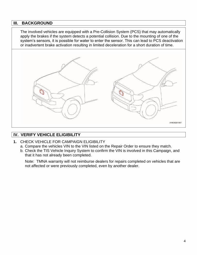
III. BACKGROUND
The involved vehicles are equipped with a Pre-Collision System (PCS) that may automatically apply the brakes if the system detects a potential collision. Due to the mounting of one of the system’s sensors, it is possible for water to enter the sensor. This can lead to PCS deactivation or inadvertent brake activation resulting in limited deceleration for a short duration of time.
IV. VERIFY VEHICLE ELIGIBILITY
1. CHECK VEHICLE FOR CAMPAIGN ELIGIBILITY a. Compare the vehicles VIN to the VIN listed on the Repair Order to ensure they match. b. Check the TIS Vehicle Inquiry System to confirm the VIN is involved in this Campaign, and
that it has not already been completed.
Note: TMNA warranty will not reimburse dealers for repairs completed on vehicles that are not affected or were previously completed, even by another dealer.

5
V. CHECK FOR VEHICLE MODIFICATIONS
1. CHECK VEHICLE FOR MODIFICATIONS a. Inspect the vehicle to determine if modifications have been made that changed the height of
the MWRS in relation to the ground (i.e., the measurement from the ground to the MWRS). The following are examples that will change the position of the MWRS:
• TRD grille installed in a non-TRD truck.
• Tires and/or wheel assemblies that are larger diameter than the OE fitment.
• Suspension modifications (lift kit).
Does the vehicle have modifications that
changed the height of the MWRS?
Continue to Section VI. OWNER
ACKNOWLEDGMENT FORM on
p.5
Refer to the separate TI for Factory
Condition (non-modified) vehicles
..YES.. ..No..
VI. OWNER ACKNOWLEDGMENT FORM
1. VERIFY SIGNATURE ON OWNER ACKNOWLEDGMENT FORM
The owner of the vehicle is required to sign an acknowledgment form before any can proceed on their vehicle. This form will explain to the customer that PCS and DRCC may not operate as designed once these updates are performed on their vehicle.
a. Confirm with the Service Manager, Assistant Service Manager, Service Writer, etc. that the required Owner Acknowledgment Form as been signed before proceeding.
If the vehicle has been modified, ensure the “Owner Acknowledgment Form” has been completed and signed by the customer before proceeding with this repair.

6
VII. CHECK FOR PRE-COLLISION SYSTEM DTC’S
1. CHECK FOR DTC’S a. Using a Techstream, perform a Health Check. b. Are there any DTC’s relating the Pre-Collision system (i.e.
C1A10, U0235, U1104) as reported by any system?
Note: This Service Campaign covers the application of the EPT-Sealer and Calibration ID update for the Pre-Collision 2 System, as detailed in these instructions. It will also cover the replacement cost of the Millimeter Wave Radar Sensor (MWRS), when necessary. It does not cover the diagnosis or replacement of any other parts on the vehicle.
Are there DTC s related to the Pre-Collision System(i.e. C1A10, U0235, U1104, etc.)?
Proceed to Section VIII.
Diagnosis of Pre-Collision
System DTC s on p. 6
Proceed to Section IX. Identify
MWRS Repair Method on p. 7
YES No
VIII. DIAGNOSIS OF PRE-COLLISION SYSTEM DTC’S
1. DETERMINE THE CAUSE OF PRE-COLLISION SYSTEM DTC’S a. Use the appropriate Repair Manual procedure to determine the cause of the Pre-Collision
System DTC’s.
Does the Repair Manual indicate that replacement of the MWRS is necessary?
Replace the MWRSDetermine the correct actions of
repair outside of this campaign
YES No
Note: Because there are multiple reasons that could cause Pre-Collision system failures, it’s critical to diagnose the system to determine the source of the trouble. This campaign will only cover the replacement of the Millimeter Wave Radar Sensor, which is located behind the Toyota emblem of the radiator grille. If the diagnostic process identifies that the DTC’s are caused by something other than the Millimeter Wave Radar Sensor, this campaign will not cover the cost associated with the repair.
Continue to IDENTIFY MWRS REPAIR METHOD on page 7

7
IX. IDENTIFY MWRS REPAIR METHOD (A or B)
1. DETERMINE THE REPAIR METHOD FOR THIS VEHICLE a. Use the following chart, reference the trim level of each vehicle to determine which repair
method to use.
Determine Repair Method by Radiator grill type
Tacoma
Repair A
Proceed to Section X. on p. 8
OR
Tacoma
Repair B
Tundra
Repair A
Tundra
Repair B
Proceed to Section XI. on p. 15
Proceed to Section XII. on p. 22
Proceed to Section XIII. on p. 26
Tacoma Tundra
OR

8
X. TACOMA - REPAIR A
TACOMA - Repair A vehicles will have radiator grilles of these designs:
Bar Type
Mesh Type
1. REMOVE RADIATOR GRILLE a. Disconnect the electrical connector. b. Disengage the clamp.
c. Apply protective tape around the radiator grille.
d. Remove the 2 screws. e. Remove the 2 clips. f. Disengage the 10 guides to remove the grille.
9
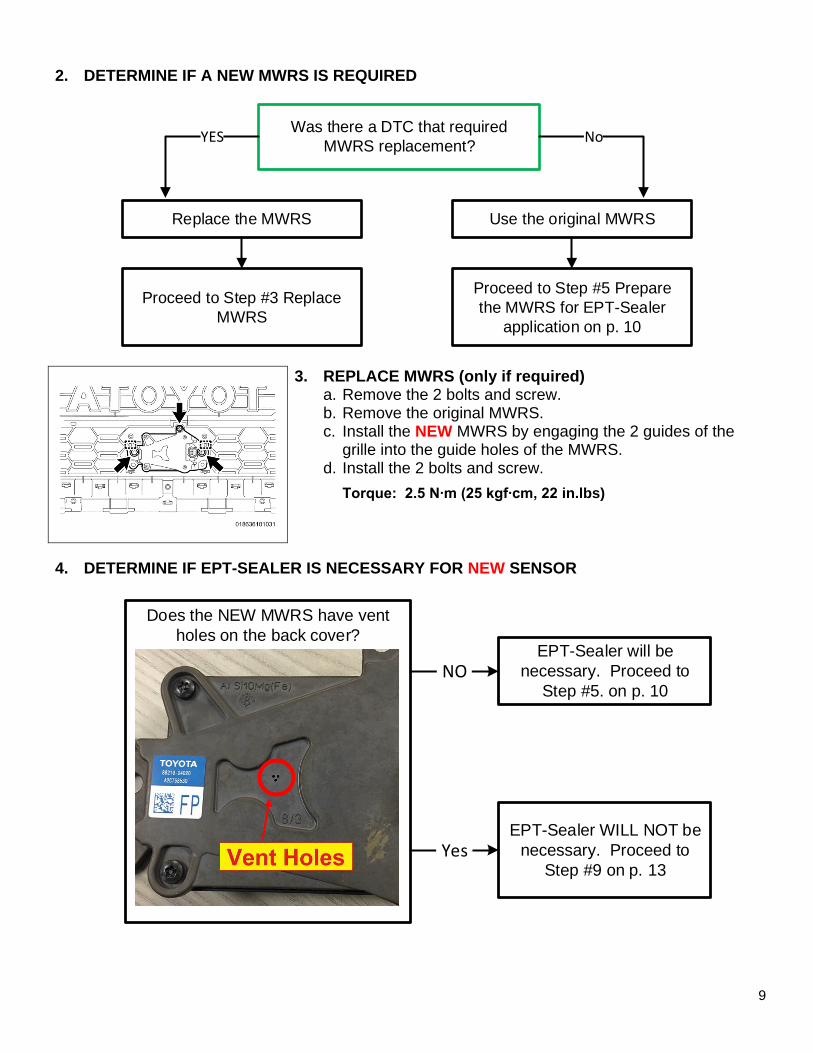
2. DETERMINE IF A NEW MWRS IS REQUIRED
Was there a DTC that required
MWRS replacement?
Replace the MWRS Use the original MWRS
YES No
Proceed to Step #5 Prepare
the MWRS for EPT-Sealer
application on p. 10
Proceed to Step #3 Replace
MWRS
3. REPLACE MWRS (only if required) a. Remove the 2 bolts and screw. b. Remove the original MWRS. c. Install the NEW MWRS by engaging the 2 guides of the
grille into the guide holes of the MWRS. d. Install the 2 bolts and screw.
Torque: 2.5 N∙m (25 kgf∙cm, 22 in.lbs)
4. DETERMINE IF EPT-SEALER IS NECESSARY FOR NEW SENSOR
EPT-Sealer WILL NOT be
necessary. Proceed to
Step #9 on p. 13
Does the NEW MWRS have vent
holes on the back cover?EPT-Sealer will be
necessary. Proceed to
Step #5. on p. 10.NO.
.Yes.

10
5. PREPARE THE MWRS FOR EPT-SEALER APPLICATION
a. Place a blanket onto the table or workbench.
b. Place the radiator grille onto the blanket, front side down.
c. Using general purpose cleaner and a clean towel, clean the back side of the MWRS sensor and the emblem area on the back side of the grille.
6. DETERMINE GRILLE TYPE
Determine Grill Type
Tacoma Bar Type Tacoma Mesh Type
Proceed to Step 7 Apply EPT
Sealer – Bar Type on p.10
Proceed to Step 8 Apply EPT
Sealer – Mesh Type on p.12
7. APPLY EPT-SEALER – Tacoma Bar Type
Note: This application will use P/N 88278-0C010. (75mm x 150mm x 5mm)
This process is only for Tacoma’s with the Bar type grille:
Video: Not available at this time
(cont.)

11
a. Apply the EPT Sealer to the back side of the MWRS in the position shown below:
• Start applying the EPT Sealer sheet to the vertical surface of the radiator grille, just above the MWRS.
• It will be necessary to push the EPT Sealer into the plastic tab at the top, creating a hole in the sealer.
• Wrap the EPT Sealer around the wire harness, as shown.
• Using heavy finger pressure, thoroughly press the entire surface of the EPT sealer to securely adhere it to all contact surfaces of the MWRS and grille.
Recommended temperature for adhesion is 50° F and above. Keep stock at room temperature.
Continue to Step 9 on page 13

12
8. APPLY EPT-SEALER – Tacoma Mesh Type
Note: This application will use P/N 88278-0C010. (75mm x 150mm x 5mm)
This process is only for Tacoma’s with the Mesh type grille:
Video: Tacoma Mesh Type Repair – EPT-Sealer Installation
a. Apply the EPT Sealer to the back side of the MWRS in the position shown below:
• Start applying the EPT Sealer sheet to the horizontal lip of the radiator grille to create a waterproof shield over the top of the sensor.
• Using heavy finger pressure, thoroughly press the entire surface of the EPT sealer to securely adhere it to all contact surfaces of the MWRS.
Recommended temperature for adhesion is 50° F and above. Keep stock at room temperature.

13
9. REINSTALL RADIATOR GRILLE
a. Engage the 10 guides to install the radiator grille.
b. Install the 2 clips.
c. Install the 2 screws.
d. Remove the protective tape.
e. Engage the clamp.
f. Connect the electrical connector.
10. DETERMINE IF MWRS ADJUSTMENT IS NECESSARY
Was the MWRS replaced with a
NEW sensor?
Proceed to Step #11 ADJUST
NEW MWRS on p. 14
Proceed to Section XIV.
DETERMINE CALIBRATION
STATUS on p. 33
YES No

14
11. ADJUST NEW MWRS
Because the modifications on this vehicle have changed the height of the MWRS from its original condition, it will be necessary to adjust the SST reflector height to match the height of the MWRS. When following the MWRS Adjustment procedure in the Repair Manual, change the height of the SST reflector to match the center of the MWRS in the grille.
a. Adjust the height of the SST reflector to the center of the MWRS in the grille. b. Follow the Repair Manual procedure to properly calibrate the MWRS:
CRUISE CONTROL: MILLIMETER WAVE RADAR SENSOR: ADJUSTMENT (RM1000000018991)
Proceed to DETERMINE CALIBRATION STATUS on p. 33

15
XI. TACOMA - REPAIR B
TACOMA Repair B vehicles will have a radiator grille of this design:
1. REMOVE RADIATOR GRILLE a. Disconnect the electrical connector. b. Disengage the clamp.
c. Apply protective tape to the bumper around the radiator grille.
d. Remove the 2 screws. e. Remove the 2 clips. f. Disengage the 10 guides by pulling the grille forward to
disengage the remaining clips.

16
2. REMOVE MWRS FROM THE GRILLE a. Place a blanket onto a table or workbench. b. Place the radiator grille onto the blanket, front die down. c. Disconnect the electrical connector.
d. Remove the 2 bolts and screw. e. Disengage the 2 guides and remove the MWRS from the
grille.
3. DETERMINE IF A NEW MWRS IS REQUIRED
Was there a DTC that required
MWRS replacement?
Replace the MWRS Use the original MWRS
YES No
Proceed to Step #5 Apply EPT-
Sealer to MWRS p. 17
Proceed to Step #4 Determine if
EPT-Sealer is Necessary for
NEW Sensor on p. 17

17
4. DETERMINE IF EPT-SEALER IS NECESSARY FOR NEW SENSOR
EPT-Sealer WILL NOT be
necessary. Proceed to
Step #9 on p. 20
Does the NEW MWRS have vent
holes on the back cover?EPT-Sealer will be
necessary. Proceed to
Step #5. on p. 17.NO.
.Yes.
5. APPLY EPT-SEALER TO MWRS
Note: This application will use P/N 88278-0C020. (46mm x 32mm x 5mm)
The EPT-Sealer will be applied in a specific way, using the following points for orientation. Please note the arrangement of corners A, B, C, D.
Video: EPT Sealer Installation Repair B
Recommended temperature for adhesion is 50° F and above. Keep stock at room temperature.

18
6. CLEAN THE APPLICATION AREA a. Using general purpose cleaner, remove all traces of
dust, dirt, and oils or grease from the application area (indicated within the red circle). Be careful not to get any liquids into the 2 vent holes.
Note: The MWRS housing has been painted white in these photos to provide more contrast in the pictures. The actual MWRS housings will be black.
Left Side
7. APPLY THE EPT SEALER a. Wear Nitrile Gloves to prevent adhesive
contamination. b. Apply the EPT-Sealer to the left side of the MWRS
to the following standard:
• Left Side View: Corner “A” of the EPT-Sealer should be placed at the inner corner of the MWRS as indicated.
• Top View: Place the EPT-Sealer on the surface of the side vent hole (it is ok to cover the side vent hole). DO NOT place the EPT Sealer on top of the ridge, as indicated with the yellow X’s.
Note: A diagram of the EPT sealer can be found on page 14.
c. Press the EPT sealer firmly into place in this area to seat it thoroughly. Use a flathead screw driver or trim tool if necessary to reach the corner.
Top View

19
d. Roll the EPT-Sealer Corner “B” onto the top edge of the MWRS sensor as shown, aligning it’s edge with the end of the metal bracket. Be sure to keep the EPT-Sealer off the upper ridge.
e. Press the EPT sealer firmly into place in this area to seat it thoroughly.
f. Bend the lower flap (Corner “C”) onto the face of the MWRS and align the edge with the edge of the upper flap and metal bracket.
g. Press the EPT-Sealer into the face of the MWRS to seat it firmly. DO NOT press in the area indicated as it’s critical there is an air gap for the vent.
ONLY PRESS THE EPT-SEALER ONTO THE UPPER FACE OF THE MWRS. DO NOT press the EPT sealer into the vent hole. It’s critical that the vent hole remains open.

20
h. Roll Corner “D” downward from the top, aligning the edge with the edge of the lower section and metal bracket.
i. Press the EPT sealer into place, being careful to leave an airgap above the rear vent hole.
8. INSPECT THE EPT-SEALER APPLICATION a. Verify that all the contact points of the EPT sealer
are thoroughly applied. b. Verify that the bottom is still open to properly
allow airflow to the rear vent hole.
Note: In case of failure during inspection, start over with a new piece of EPT-Sealer.
9. INSTALL THE MWRS a. Engage the 2 guides of the radiator grille into the guide holes of the MWRS. b. Install the 2 bolts and screw.
Torque: 2.5 N∙m (25 kgf∙cm, 22 in.lbs)
10. REINSTALL THE RADIATOR GRILLE a. Engage the 10 guides to install the radiator grille. b. Install the 2 clips. c. Install the 2 screws. d. Remove the protective tape. e. Engage the clamp. f. Connect the electrical connector.

21
11. ADJUST NEW MWRS
Because the modifications on this vehicle have changed the height of the MWRS from its original condition, it will be necessary to adjust the SST reflector height to match the height of the MWRS. When following the MWRS Adjustment procedure in the Repair Manual, change the height of the SST reflector to match the center of the MWRS in the grille.
a. Adjust the height of the SST reflector to the center of the MWRS in the grille. b. Follow the Repair Manual procedure to properly calibrate the MWRS.
CRUISE CONTROL: MILLIMETER WAVE RADAR SENSOR: ADJUSTMENT (RM1000000018991)
Proceed to DETERMINE CALIBRATION STATUS on p. 33
22
XII. TUNDRA - REPAIR A
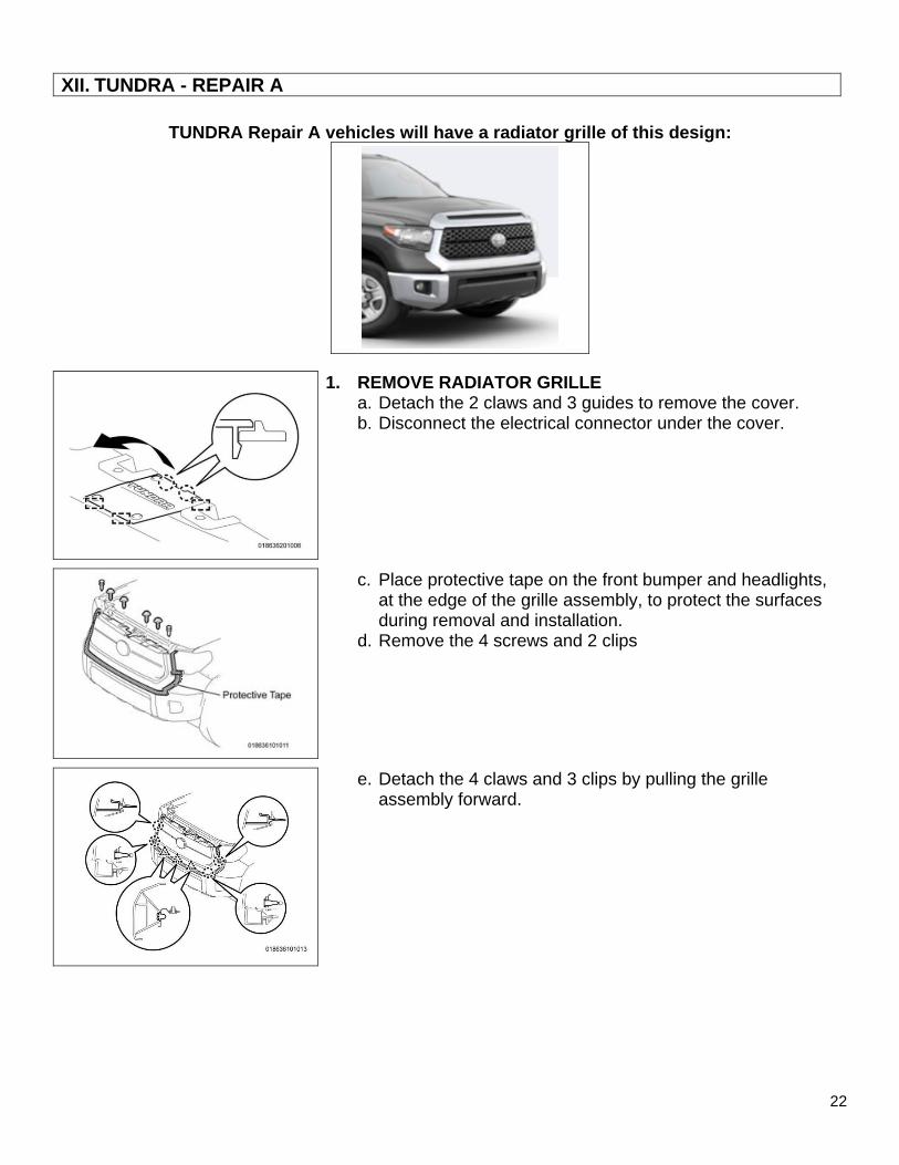
TUNDRA Repair A vehicles will have a radiator grille of this design:
1. REMOVE RADIATOR GRILLE a. Detach the 2 claws and 3 guides to remove the cover. b. Disconnect the electrical connector under the cover.
c. Place protective tape on the front bumper and headlights, at the edge of the grille assembly, to protect the surfaces during removal and installation.
d. Remove the 4 screws and 2 clips
e. Detach the 4 claws and 3 clips by pulling the grille assembly forward.

23
2. DETERMINE IF A NEW MWRS IS REQUIRED
Was there a DTC that required
MWRS replacement?
Proceed to Step #3 REPLACE
MWRS on p. 23
Proceed to Step #5 PREPARE
THE MWRS FOR EPT-SEALER
APPLICATION on p. 24
YES No
3. REPLACE MWRS (only if required) a. Remove the 2 bolts and screw. b. Remove the original MWRS. c. Install the NEW MWRS by engaging the 2 guides of the
grille into the guide holes of the MWRS. d. Install the 2 bolts and screw.
Torque: 2.5 N∙m (25 kgf∙cm, 22 in.lbs)
4. DETERMINE IF EPT-SEALER IS NECESSARY FOR NEW SENSOR
EPT-Sealer WILL NOT be
necessary. Proceed to
Step #7 on p. 24
Does the NEW MWRS have vent
holes on the back cover?EPT-Sealer will be
necessary. Proceed to
Step #5. on p. 24.NO.
.Yes.

24
5. PREPARE THE MWRS FOR EPT APPLICATION
a. Place a blanket onto the table or workbench.
b. Place the radiator grille onto the blanket, front side down.
c. Using general purpose cleaner and a clean towel, clean the back side of the MMRS sensor and the emblem area on the back side of the grille.
6. APPLY EPT-SEALER
Note: This application will use P/N 88278-0C010. (75mm x 150mm x 5mm)
Video: Tundra EPT Sealer Installation Type A
a. Apply the EPT Sealer to the back face of the MWRS in the position shown below. b. Roll the EPT sealer onto the inside lip of the radiator grille to create a waterproof shield over
the top of the sensor. c. Using finger pressure, thoroughly press the entire surface of the EPT sealer to securely
adhere it to all contact surfaces.
Recommended temperature for adhesion is 50° F and above. Keep stock at room temperature.
7. REINSTALL THE RADIATOR GRILLE a. Attach the 4 claws and 3 clips to install the grille. b. Install the 4 screws and 2 clips. c. Remove the protective tape. d. Connect the electrical connector. e. Reinstall the cover.
25
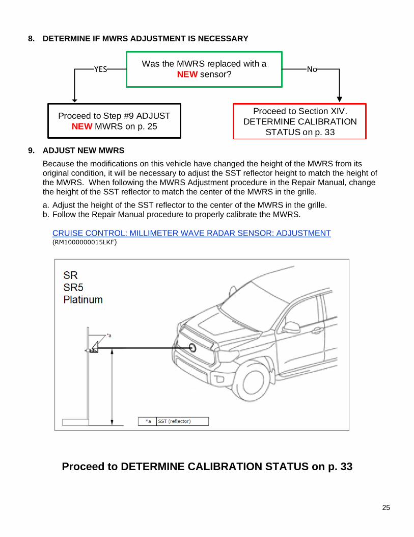
8. DETERMINE IF MWRS ADJUSTMENT IS NECESSARY
Was the MWRS replaced with a
NEW sensor?
Proceed to Step #9 ADJUST
NEW MWRS on p. 25
Proceed to Section XIV.
DETERMINE CALIBRATION
STATUS on p. 33
YES No
9. ADJUST NEW MWRS
Because the modifications on this vehicle have changed the height of the MWRS from its original condition, it will be necessary to adjust the SST reflector height to match the height of the MWRS. When following the MWRS Adjustment procedure in the Repair Manual, change the height of the SST reflector to match the center of the MWRS in the grille.
a. Adjust the height of the SST reflector to the center of the MWRS in the grille. b. Follow the Repair Manual procedure to properly calibrate the MWRS.
CRUISE CONTROL: MILLIMETER WAVE RADAR SENSOR: ADJUSTMENT (RM1000000015LKF)
Proceed to DETERMINE CALIBRATION STATUS on p. 33
26
XIII. TUNDRA - REPAIR B
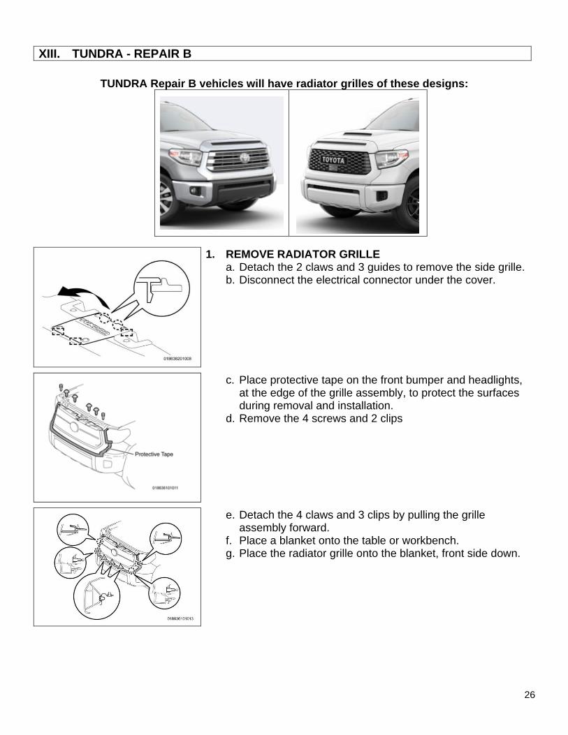
TUNDRA Repair B vehicles will have radiator grilles of these designs:
1. REMOVE RADIATOR GRILLE a. Detach the 2 claws and 3 guides to remove the side grille. b. Disconnect the electrical connector under the cover.
c. Place protective tape on the front bumper and headlights, at the edge of the grille assembly, to protect the surfaces during removal and installation.
d. Remove the 4 screws and 2 clips
e. Detach the 4 claws and 3 clips by pulling the grille assembly forward.
f. Place a blanket onto the table or workbench. g. Place the radiator grille onto the blanket, front side down.
27
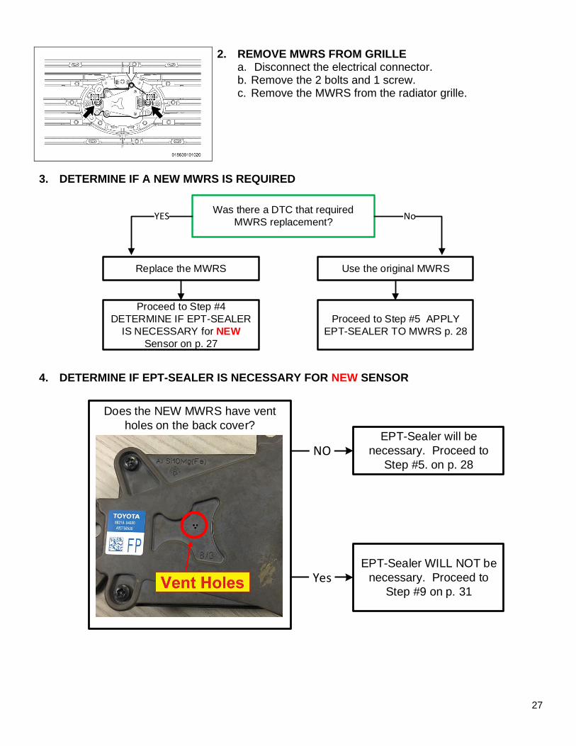
2. REMOVE MWRS FROM GRILLE a. Disconnect the electrical connector. b. Remove the 2 bolts and 1 screw. c. Remove the MWRS from the radiator grille.
3. DETERMINE IF A NEW MWRS IS REQUIRED
Was there a DTC that required
MWRS replacement?
Replace the MWRS Use the original MWRS
YES No
Proceed to Step #5 APPLY
EPT-SEALER TO MWRS p. 28
Proceed to Step #4
DETERMINE IF EPT-SEALER
IS NECESSARY for NEW
Sensor on p. 27
4. DETERMINE IF EPT-SEALER IS NECESSARY FOR NEW SENSOR
EPT-Sealer WILL NOT be
necessary. Proceed to
Step #9 on p. 31
Does the NEW MWRS have vent
holes on the back cover?EPT-Sealer will be
necessary. Proceed to
Step #5. on p. 28.NO.
.Yes.

28
5. APPLY EPT-SEALER TO MWRS
Note: This application will use P/N 88278-0C020. (46mm x 32mm x 5mm)
The EPT-Sealer will be applied in a specific way, using the following points for orientation. Please note the arrangement of corners A, B, C, D.
Video: EPT Sealer Installation Repair B
Recommended temperature for adhesion is 50° F and above. Keep stock at room temperature.
6. CLEAN THE APPLICATION AREA a. Using general purpose cleaner, remove all traces of
dust, dirt, and oils or grease from the application area (indicated within the red circle). Be careful not to get any liquids into the 2 vent holes.
Note: The MWRS housing has been painted white in these photos to provide more contrast in the pictures. The actual MWRS housings will be black.

29
Left Side
7. APPLY THE EPT SEALER a. Wear Nitrile Gloves to prevent adhesive
contamination. b. Apply the EPT-Sealer to the left side of the MWRS
to the following standard:
• Left Side View: Corner “A” of the EPT-Sealer should be placed at the inner corner of the MWRS as indicated.
• Top View: Place the EPT-Sealer on the surface of the side vent hole (it is ok to cover the side vent hole). DO NOT place the EPT Sealer on top of the ridge, as indicated with the yellow X’s.
Note: A diagram of the EPT sealer can be found on page 15.
c. Press the EPT sealer firmly into place in this area to seat it thoroughly. Use flathead screw driver or trim tool if necessary to reach the corner.
Top View

30
d. Roll the EPT-Sealer Corner “B” onto the top edge of the MWRS sensor as shown, aligning it’s edge with the end of the metal bracket. Be sure to keep the EPT-Sealer off the upper ridge.
e. Press the EPT sealer firmly into place in this area to seat it thoroughly.
f. Bend the lower flap (Corner “C”) onto the face of the MWRS and align the edge with the edge of the upper flap and metal bracket.
g. Press the EPT-Sealer into the face of the MWRS to seat it firmly. DO NOT press in the area indicated as it’s critical there is an air gap for the vent.
ONLY PRESS THE EPT SEALER ONTO THE FACE OF THE MWRS. DO NOT press the EPT sealer into the vent hole. It’s critical that the vent hole remains open.
h. Roll Corner “D” downward from the top, aligning the edge with the edge of the lower section and metal bracket.
i. Press the EPT sealer into place, being careful to leave an airgap above the rear vent hole.

31
8. INSPECT THE EPT-SEALER APPLICATION a. Verify that all the contact points of the EPT sealer
are thoroughly applied. b. Verify that the bottom is still open to properly
allow airflow to the rear vent hole.
Note: In case of failure during inspection, start over with a new piece of EPT-Sealer.
9. REINSTALL THE MWRS a. Engage the 2 guides of the grille into the guide holes of the MWRS. b. Install the 2 bolts and screw.
Torque: 2.5 N∙m (25 kgf∙cm, 22 in.lbs)
10. REINSTALL THE RADIATOR GRILLE a. Engage the 4 claws and 3 clips to install the radiator grille assembly. b. Install the 4 screws and 2 clips. c. Remove the protective tape. d. Connect the electrical connector. e. Install the Side Grille by engaging the 2 claws and 3 guides.

32
11. ADJUST THE MWRS
Because the modifications on this vehicle have changed the height of the MWRS from its original condition, it will be necessary to adjust the SST reflector height to match the height of the MWRS. When following the MWRS Adjustment procedure in the Repair Manual, change the height of the SST reflector to match the center point height of the MWRS in the grille.
a. Adjust the height of the SST reflector to the center point of the MWRS in the grille. b. Follow the Repair Manual procedure to properly calibrate the MWRS.
CRUISE CONTROL: MILLIMETER WAVE RADAR SENSOR: ADJUSTMENT (RM1000000015LKF)

33
XIV. DETERMINE CALIBRATION STATUS
1. CHECK FOR DTC’S a. Using a Techstream, perform a Health Check.
Note: This Service Campaign covers only the application of the EPT-Sealer and Calibration ID update for the Pre-Collision 2 System, as detailed in these instructions. It does not cover the diagnosis or replacement of any other parts on the vehicle.
2. CHECK CURRENT CALIBRATION a. Locate the Update column for the Pre-Collision 2 System in the Stored Data tab. b. Determine the status of an available update; indicated by a Yes or No.
Is there an update available to the
Pre-Collision 2 System?
Proceed to Section XV. VEHICLE
PREPARATION on p. 34Proceed to TURN PCS OFF
on p. 38
YES No

34
XV. VEHICLE PREPARATION
1. VEHICLE PREPARATION a. Confirm the following conditions:
• Vehicle in the IG position (engine off).
• Transaxle in Park.
• Parking brake engaged.
• Turn off all electrical accessories (i.e. climate control, audio system, etc.)
• Headlight switch in the DRL OFF position.
• Windshield wiper switch in the OFF position.
2. CONNECT THE 12v BATTERY TO A POWER SUPPLY (GR8) a. Connect the GR8 or other type of a power supply (not a battery charger) to the 12v battery. b. Select the Power Supply Mode from the Charge Menu of the GR8.
A power supply MUST be used during reprogramming. ECU damage will occur if the battery voltage is not properly maintained during this re-flash procedure.
Note: A power supply must be connected directly to the 12v battery terminals and NOT the remote jump posts under the hood (if equipped).
3. VERIFY TECHSTREAM SETUP a. Verify that the Techstream meets the following conditions:
• The latest version of software is loaded.
• The Techstream battery is fully charged. If not, connect the Techstream to a 120v source.
• The DLCIII cable is in good condition.
The Techstream’s battery voltage must be maintained during the update procedure. If necessary, plug the Techstream into a 120v outlet during this procedure.
Note: If the Techstream’s communication with the vehicle fails during the update procedure, the ECU will be damaged.

35
XVI. UPDATE CALIBRATION
1. UPDATE THE CALIBRATION ID
a. Identify the vehicles Current CID for the Pre-Collision 2 System on the Stored Data tab.
b. Locate the vehicles Current CID in the chart on the following page. c. Select the corresponding NEW CID link to load the update. d. Follow the on-screen instructions to complete the Calibration Update procedure.
The CID Update Procedure is detailed in T-SB-0134-16. Please reference this Bulletin for more detailed procedures and information.
Current CID

36
Be extremely careful to select the correct NEW CID that corresponds to the Current CID.
Vehicle Specification Millimeter Wave Radar Sensor Calibrations
Model Type Current CID New CID
TUNDRA
Non-TRD Pro
8821F0C01100
8821F0C01500 8821F0C01200
8821F0C01300
8821F0C01400
TRD Pro
8821F0C03100
8821F0C03500 8821F0C03200
8821F0C03300
8821F0C03400
TACOMA
Non-TRD Pro
8821F0401100
8821F0405100 8821F0401200
8821F0405000
TRD Pro
8821F0402100
8821F0406100 8821F0402200
8821F0406000
2. PERFORM VERIFICATION HEALTH CHECK a. Clear DTC’s that may have set during the re-flash
procedure. b. Re-run the Health Check to confirm that no DTC’s
reappear.
THIS VERIFICATION HEALTH CHECK IS NECESSARY to update the results and CID’s to the National database.

37
3. CONFIRM CID UPDATE a. On the Stored Data tab, confirm the following for the Pre-Collision 2 System:
• The CID listed matches the NEW CID that was installed in Step 1 above.
Note: The Update column may list “YES” for an update available, even though the correct CID has been properly installed as detailed in these instructions. The available update is for the Permanent Disabling of the PCS and DRCC system. This Permanent Disabling update SHOULD NOT BE PERFORMED unless the vehicle meets the criteria for this procedure and the owner has completed the required disclosure. This procedure is intended to be used only on vehicle’s that have extensive modifications that effect the operation of the PCS and DRCC systems. If this Permanent Disabling CID is installed, the replacement of the MWRS sensor will be required to reinitiate the systems. This expense will not be covered by warranty.
Check that CID matches the NEW CID from Step 1 above. “YES” may be indicated even if the correct CID is installed

38
XVII. COMPLETE INSTALLATIONS
1. UPDATE CUSTOMIZABLE SETTINGS
The Pre-Collision System (PCS) defaults it’s operating mode to ON after each ignition cycle, even if the system had been turned off (using the meter control switch) during the previous ignition cycle. Because of the ride height modifications on this vehicle, the PCS system may not operate as designed. Therefore, it will be necessary to change this function so that it can remain OFF each time the vehicle is started. Changing the PCS Operation State Retention Setting will default the PCS system to it’s last setting during each key cycle. Therefore, the system can remain OFF during each ignition cycle.
a. Follow the instructions as detailed in T-SB-0059-18 to change the PCS Operation State Retention Setting:
TSB: Pre-Collision System (PCS) Customizable Features (T-SB-0059-18)
2. TURN PCS OFF
Once the Customizable Settings have been updated, it will now be necessary to turn the PCS system to OFF. Follow these steps to turn the PCS OFF:
a. Press the “<” or “>” (#1 below) of the meter control switch (right side of steering wheel) until
the is displayed. Press (#2 below).
b. Press “˄” of “˅” of the meter control to select “PCS” and press .
c. Press “˄” of “˅” of the meter control to select “OFF” and press .
Note: With the PCS set to OFF, the PCS warning light will illuminate, and a message will be displayed on the multi-information display.
Tundra Tacoma

39
3. REMOVE POWER SUPPLY
a. Remove the power supply from the battery.
4. OWNERS MANUAL INSERT a. Print the Owner’s Manual Insert:
SSC K0B Millimeter Wave Radar Sensor Owner’s Manual Insert
b. Check the appropriate boxes on the bottom to indicate the modifications present on the vehicle.
c. Place the Insert into Section 4-5 of the Owner’s Manual.

40
5. APPLY K0B MODIFIED VEHICLE LABEL a. Apply the yellow K0B Modified Vehicle Label to the left side of the steering column as shown
in the photo below.
Note: Each dealership has received an initial shipment of these labels, sent to the attention of the Service Manager. Additional labels are available for order through the Material Distribution Center.
Tacoma Tundra
(K0B Modified Vehicle Label)
Apply the K0B Modified Vehicle Label to the left side of the steering column

41
XVIII. CUSTOMER HEALTH CHECK REPORT
1. PRINT CUSTOMER HEALTH CHECK REPORT a. From the Stored Data tab, select the Customer Health Check Report button (TIS will launch
when button is pressed).
b. Log in to TIS. c. Input Vehicle Mileage and Repair Order number. d. Check the “Performed” campaign button for campaign K0B. e. Select the Report button.
f. Confirm Customer Health Check Report information is correct.
g. Print Customer Health Check Report from TIS. h. Sign and provide to the customer.
Customer Health
Check Button

42
2. ATTACH THE AUTHORIZED VEHICLE MODIFICATION LABEL a. Fill out the label. b. Affix the label to the under-side of the hood.
1 Pre Collision
2 (Calibration ID’s)
3 (Dealer Code)
4 (Date Completed)
5 Safety Recall K0B
Calibration ID’s listed for the Pre Collision 2 System after completing the final Health Check. The CID’s will vary for car to car.
◄ VERIFY REPAIR QUALITY ►
• Confirm that the EPT-Sealer is properly applied.
• Confirm that the EPT-Sealer has good adhestion to the MWRS.
• Confirm that the radiator grille is reinstalled correctly.
• Confirm that the system has been properly calibrated, if necessary.
• Confirm that the PCS System if turned OFF.
If you have any questions regarding this update, please contact your regional representative.

43
XIX. APPENDIX
A. PARTS DISPOSAL As required by Federal Regulations, please make sure all recalled parts (original parts) removed from the vehicle are disposed of in a manner in which they will not be reused, unless requested for parts recovery return.
B. CAMPAIGN DESIGNATION DECORDER
H 0 A
Year Campaign is Launched
B = 2011
C = 2012
D = 2013
E = 2014
F = 2015
G = 2016
H = 2017
Etc...
Repair Phase
1st Campaign = A
2nd
Campaign = B
3rd
Campaign = C
4th Campaign = D
5th Campaign = E
27th Campaign = 1
28th Campaign = 2
Etc...
Current Campaign Letter
for this year
0 = Remedy
1 = Interim (Remedy not yet
available) will change to
when the Remedy is available
(May use other characters in
unique cases)
Examples: C1B = Launched in 2012, Interim Phase, 2nd Campaign Launched in 2012 E0A = Launched in 2014, Remedy Phase, 1st Campaign Launched in 2014 H0A = Launched in 2017, Remedy Phase, 1st Campaign Launched in 2017.


![Cub Scout Advancement Modifications 12.5.16[1] to CS pro… · CUB SCOUT ADVANCEMENT MODIFICATIONS Fall 2016 TASK FORCE NOTES ON CUB SCOUT ADVANCEMENT MODIFICATIONS Purpose With one](https://img.pdfslide.us/doc/110x75/6054fa3b8baeb77fe65e8e87/cub-scout-advancement-modifications-125161-to-cs-pro-cub-scout-advancement.jpg)