Embed Size (px)
Citation preview
Vehicle to Vehicle WirelessCommunication Protocol for Collision
Warning
A Seminar Presentationby
Arunkumar AnandRoll no: 2 , S7 ECE
GEC, Wayanand
In the Partial FulfillmentOf the Requirements for the Degree of
B.Tech in Electronics & Comm. Engineering
Dept. of Electronics & Communication EngineeringGovernment Engineering College, Wayanad
28 September 2006
Copyright c© 2006Arunkumar Anand
http://arunkumaranand.bizhat.com/seminar
Acknowledgements
First of all let me thank our HOD Prof. Hari, Department of ECE forinsisting us to choose better topic in the seminar presentation. He madeus to select currently relevant applications particularly on communicationfield by referring us to well reputed international journals such as IEEECommunication Magazine.
Then, Let me show my sincere gratitude to our Lecturer Rajeev Rajan,Dept. of ECE, the person behind the successful completion of our seminar.Rather than being our Seminar coordinator he sincerely helped us in eachstage of our seminar developments. He recommended us to make the seminarreports in LATEX an internationally accepted typesetting tool particularly forscientific presentation.
Again I’m obliged to my parents and my sister for giving me freedom andsupport in the entire endeavor for the completion of my seminar.
Above all I’m grateful to the supreme grace, without his help I couldn’taccomplish anything.
Abstract
This article presents an overview of recently developing vehicular communica-tion technology particularly describing Vehicle to Vehicle (V2V) communica-tion using IEEE and ASTM adopted Dedicated Short Range Communication(DSRC) Standard. This paper also discusses some of the application require-ments and congestion control policies. Lastly, a real life implementation ofV2V and DSRC standard that support it are analysed.
Contents
AcknowledgementAbstract
1 Introduction . . . . . . . . . . . . . . . . . . . . . . . . . . . . 11.1 Human driver’s limitations . . . . . . . . . . . . . . . . 11.2 Need of ITS . . . . . . . . . . . . . . . . . . . . . . . . 2
2 Next Generation Vehicular Scenario . . . . . . . . . . . . . . . 43 Vehicular Communication . . . . . . . . . . . . . . . . . . . . 5
3.1 Radio Bands used in IVC . . . . . . . . . . . . . . . . 53.2 Different Vehicular Communications . . . . . . . . . . 63.3 DSRC . . . . . . . . . . . . . . . . . . . . . . . . . . . 7
3.3.1 DSRC Applications . . . . . . . . . . . . . . . 84 Application Challenges . . . . . . . . . . . . . . . . . . . . . . 11
4.1 Delay Requirements . . . . . . . . . . . . . . . . . . . 114.2 Multiple co-existing AVs . . . . . . . . . . . . . . . . . 124.3 Differentiation of EWMs . . . . . . . . . . . . . . . . . 13
5 VCWC Protocol . . . . . . . . . . . . . . . . . . . . . . . . . . 145.1 Assumptions . . . . . . . . . . . . . . . . . . . . . . . . 155.2 State Transitions of AVs . . . . . . . . . . . . . . . . . 15
6 Related Works . . . . . . . . . . . . . . . . . . . . . . . . . . . 187 Conclusion . . . . . . . . . . . . . . . . . . . . . . . . . . . . . 21
References 22
Appendix 241 Abbreviation . . . . . . . . . . . . . . . . . . . . . . . . . . . 25
i
List of Figures
1.1 V2V Helps to improve road safety. . . . . . . . . . . . . . . . . 11.2 ITS Architecture . . . . . . . . . . . . . . . . . . . . . . . . . 33.1 Different Vehicular Comm. . . . . . . . . . . . . . . . . . . . . 63.2 DSRC Protocol Architecture . . . . . . . . . . . . . . . . . . . 83.3 DSRC Spectrum . . . . . . . . . . . . . . . . . . . . . . . . . 104.1 Reaction to Sudden Brake . . . . . . . . . . . . . . . . . . . . 124.2 Muliple AVs . . . . . . . . . . . . . . . . . . . . . . . . . . . . 135.1 Non flagger AV . . . . . . . . . . . . . . . . . . . . . . . . . . 165.2 Flagger AV . . . . . . . . . . . . . . . . . . . . . . . . . . . . 175.3 Differentiation of EWMs . . . . . . . . . . . . . . . . . . . . . 187.1 Comment . . . . . . . . . . . . . . . . . . . . . . . . . . . . . 22
ii
List of Tables
3.1 DSRC Specifications . . . . . . . . . . . . . . . . . . . . . . . 83.2 Different DSRC Appl. . . . . . . . . . . . . . . . . . . . . . . 9
iii
V2V Wireless Communication Protocol for Collision Warning
1 Introduction
Traffic accidents have been taking thousands of lives each year, outnumberingany deadly diseases or natural disasters. As far as India is considered, Indiahaving less than 1% of the world’s vehicles, the country accounts for 6% oftotal road accidents across the globe and 10% of total road fatalities [13].Every year in the United States, about six million traffic accidents occur dueto automobile crashes. In 2003 alone, these accidents accounted for $230billion in damaged property, 2,889,000 nonfatal injuries, and 42,643 deaths[14]. While different factors contribute to vehicle crashes, such as vehiclemechanical problems and bad weather, driver behavior is considered to bethe leading cause of more than 90 percent of all accidents. The inability ofdrivers to react in time to emergency situations often creates a potential forchain collisions, in which an initial collision between two vehicles is followedby a series of collisions involving the following vehicles.
Studies [15] show that about 60% roadway collisions could be avoidedif the operator of the vehicle was provided warning at least one-half secondprior to a collision.
1.1 Human driver’s limitations
In emergency situations, a driver typically relies on the tail brake light of thecar immediately ahead to decide his or her own braking action. Under typicalroad situations, this is not always the best collision avoidance strategy forvarious reasons. In many cases, the ability to detect an emergency eventoccurring at some distance ahead is limited by the inability of drivers to seepast the vehicle in front of them.
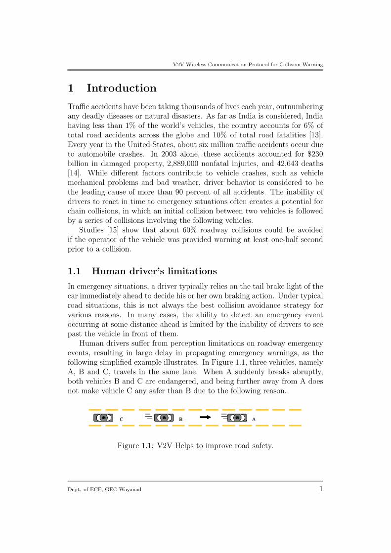
Human drivers suffer from perception limitations on roadway emergencyevents, resulting in large delay in propagating emergency warnings, as thefollowing simplified example illustrates. In Figure 1.1, three vehicles, namelyA, B and C, travels in the same lane. When A suddenly breaks abruptly,both vehicles B and C are endangered, and being further away from A doesnot make vehicle C any safer than B due to the following reason.
Figure 1.1: V2V Helps to improve road safety.
Dept. of ECE, GEC Wayanad 1
V2V Wireless Communication Protocol for Collision Warning
• Line-of-sight limitation of brake light: Typically, a driver can only seethe brake light from the vehicle directly in front. Thus, very likelyvehicle C will not know the emergency at A until B brakes.
• Large processing/forwarding delay for emergency events: Driver reac-tion time, i.e., from seeing the brake light of A to stepping on the brakefor the driver of vehicle B, typically ranges from 0.7 seconds to 1.5 sec-onds [16],[2], At a speed of 70 mph, this means that between 75 and 150ft is traveled before any reaction occurs; which results in large delay inpropagating the emergency warning.
1.2 Need of Intelligent Transportation System (ITS)
Chain collisions can be potentially avoided, or their severity lessened, byreducing the delay between the time of an emergency event and the timeat which the vehicles behind are informed about it [4]. One way to providemore time to drivers to react in emergency situations is to develop IntelligentTransportation System applications using emerging wireless communicationtechnology. The primary benefit of such communication will be to allowthe emergency information to be propagated among vehicles much quickerthan a traditional chain of drivers reacting to the brake lights of vehiclesimmediately ahead.
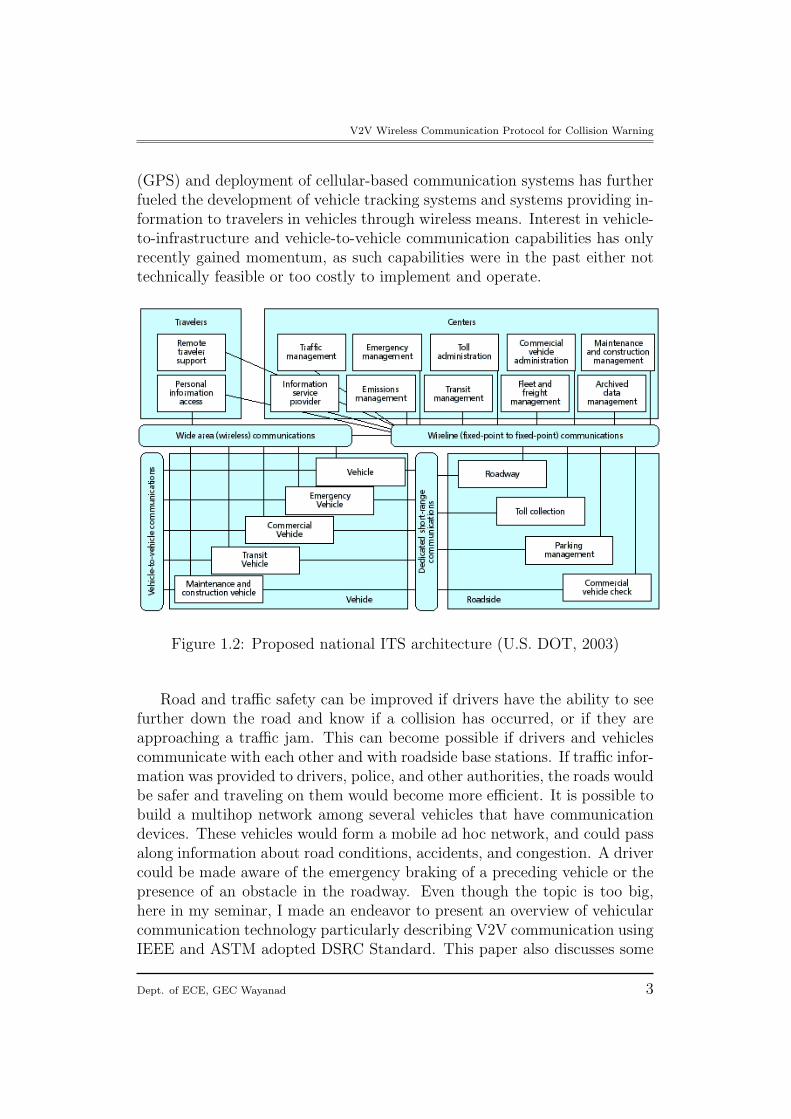
Figure 2 details the system architecture proposed by the U.S. Depart-ment of Transportation U.S. DOT, 2003) for the development of IntelligentTransportation Systems (ITS) [17]. The architecture is defined around fourbasic components linked by a communication infrastructure.
The four generic types of telecommunications systems are:
• Vehicle-to-Vehicle
• Dedicated Short Range Communications (DSRC)
• Wide Area Wireless
• Wireline
Wireline and Wireless are the two primary types of telecommunicationsarchitectures shown in the diagram, with Vehicle-to-Vehicle (V2V) and DSRCbeing two applications of wireless. There is no distinct requirement to useRF, Copper, or Fiber Optics as a transmission medium. Nor is there anysuggestion as to the network topology: point-to-point, star, ring, mesh, etc.More recently, the combined availability of the Global Positioning System
Dept. of ECE, GEC Wayanad 2
V2V Wireless Communication Protocol for Collision Warning
(GPS) and deployment of cellular-based communication systems has furtherfueled the development of vehicle tracking systems and systems providing in-formation to travelers in vehicles through wireless means. Interest in vehicle-to-infrastructure and vehicle-to-vehicle communication capabilities has onlyrecently gained momentum, as such capabilities were in the past either nottechnically feasible or too costly to implement and operate.
Figure 1.2: Proposed national ITS architecture (U.S. DOT, 2003)
Road and traffic safety can be improved if drivers have the ability to seefurther down the road and know if a collision has occurred, or if they areapproaching a traffic jam. This can become possible if drivers and vehiclescommunicate with each other and with roadside base stations. If traffic infor-mation was provided to drivers, police, and other authorities, the roads wouldbe safer and traveling on them would become more efficient. It is possible tobuild a multihop network among several vehicles that have communicationdevices. These vehicles would form a mobile ad hoc network, and could passalong information about road conditions, accidents, and congestion. A drivercould be made aware of the emergency braking of a preceding vehicle or thepresence of an obstacle in the roadway. Even though the topic is too big,here in my seminar, I made an endeavor to present an overview of vehicularcommunication technology particularly describing V2V communication usingIEEE and ASTM adopted DSRC Standard. This paper also discusses some
Dept. of ECE, GEC Wayanad 3
V2V Wireless Communication Protocol for Collision Warning
of the application requirements and congestion control policies.
2 Next Generation Vehicular Scenario
Now the vehicle manufactures are making vehicle with sixth sense. Usingvehicle-to-vehicle (V2V) communication, a vehicle can detect the positionand movement of other vehicles up to a quarter of a mile away. In a worldwhere vehicles are equipped with a simple antenna, a computer chip andGPS (Global Positioning System) technology your car will know where theother vehicles are, additionally other vehicles will know where you are too –whether it is in blind spots, stopped ahead on the highway but hidden fromview, around a blind corner or blocked by other vehicles. The vehicles can an-ticipate and react to changing driving situations and then instantly warn thedrivers with chimes, visual icons and seat vibrations. If the driver doesn’t re-spond to the alerts, the car can bring itself to a safe stop, avoiding a collision.A number of technology based systems have evolved to support transporta-tion operations, traffic management, traveler information, fleet management,and incident control. These include:
• Automated Traffic Signal Systems
• Commercial Vehicle Operations (CVO)
• Freeway Management
• Traveler Information
• Remote Weather Information Systems
• Incident Management
• Special Events
• Parking Space locater in Cities.
• Presence of obstacles on road.
• Emergency Braking of a preceding vehicle.
• Information about Blind Crossing, School proximity, Railway crossingetc
• Entries to Highways.
Dept. of ECE, GEC Wayanad 4
V2V Wireless Communication Protocol for Collision Warning
• High Speed Internet Access.
• Nearest Petrol Pump, Workshop etc
• Electronic Toll Collection.
To encourage the development of V2V, the Federal Communications Com-mission has cleared the 5.9-gigahertz band for dedicated short-range commu-nications (DSRC) among cars, other cars, and roadside transceivers. Evennow General Motors had made DSRC-equipped Cadillac CTS that stops it-self to avoid accidents. Its enhanced stability-control system predicts whereit’s headed like, into the rear end of another DSRC car stopped in the middleof the road and prompts the onboard computer to apply the brakes withoutany input from the driver.
3 Vehicular Communication
3.1 Radio Bands Used in Inter-Vehicle Communica-tion
This section[3] discusses the different frequency bands that can be used inIVC. Bluetooth and Ultra-Wideband (UWB) technologies are explored insome detail. It is possible for communicating vehicles to use both infraredand radio waves. VHF and microwaves are a type of broadcast communica-tion while infrared and millimeter waves are a type of directional communi-cation. Microwaves are used most often. For instance, 75 MHz is allottedin the 5.9 GHz band for dedicated short range communication (DSRC). It ispossible to use Bluetooth, which operates in the 2.4 GHz industry, science,and medicine (ISM) band, to set up the communication between two vehi-cles. It is reliable up to a speed of 80 km/h and range of 80 m. However, itcan take up to 3 seconds to establish the communication. Also, since Blue-tooth requires a master and slave setup, the master could potentially refusea communication request. In addition, the master may already be commu-nicating with another slave, which would lower the possible communicationrate. An alternative to Bluetooth is a new radio frequency technique calledUWB. Because of t he wideband nature of the signal, UWB has been used inradar applications. The Federal Communication Commission (FCC) refersto UWB technology as having high values of fractional bandwidth (¿ 0.25).The main advantages of UWB technology are its high data rate, low cost,and immunity to interference. On the other hand, it could possibly inter-fere with other existing radio services, for instance, the Global Positioning
Dept. of ECE, GEC Wayanad 5
V2V Wireless Communication Protocol for Collision Warning
System (GPS). The fact that UWB could potentially interfere with commu-nication sources is a technical problem that must be solved before it couldbe used in IVC systems. Also, there is a concern that UWB’s radio coveragecould extend to uninvolved vehicles, which could generate false or irrelevantinformation.
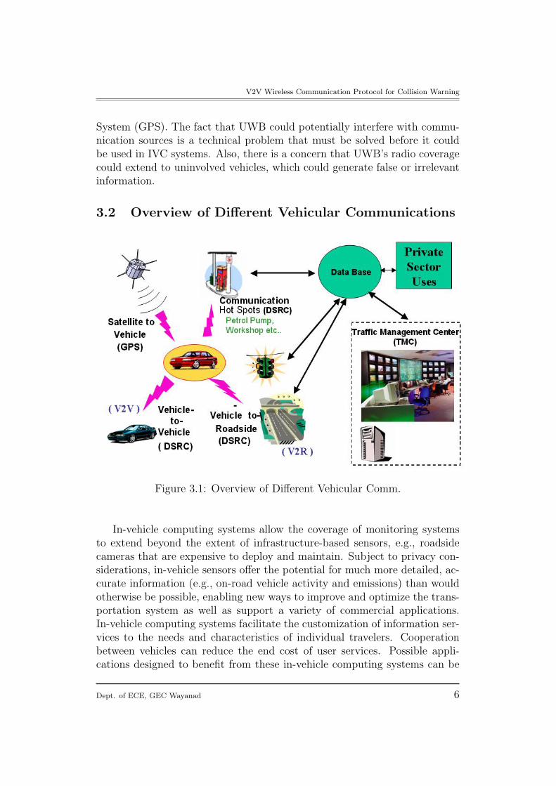
3.2 Overview of Different Vehicular Communications
Figure 3.1: Overview of Different Vehicular Comm.
In-vehicle computing systems allow the coverage of monitoring systemsto extend beyond the extent of infrastructure-based sensors, e.g., roadsidecameras that are expensive to deploy and maintain. Subject to privacy con-siderations, in-vehicle sensors offer the potential for much more detailed, ac-curate information (e.g., on-road vehicle activity and emissions) than wouldotherwise be possible, enabling new ways to improve and optimize the trans-portation system as well as support a variety of commercial applications.In-vehicle computing systems facilitate the customization of information ser-vices to the needs and characteristics of individual travelers. Cooperationbetween vehicles can reduce the end cost of user services. Possible appli-cations designed to benefit from these in-vehicle computing systems can be
Dept. of ECE, GEC Wayanad 6
V2V Wireless Communication Protocol for Collision Warning
generally classified as safety and non-safety applications. Safety applicationsinclude, e.g., collision avoidance and cooperative driving. Non-safety appli-cations include traffic information propagation, toll service, Internet access,tourist information, cooperative gaming and entertainment, etc. A V2V net-work consists of instrumented vehicles equipped with on-board computingand wireless communication devices, a GPS device enabling the vehicle totrack its spatial and temporal trajectory, a pre-stored digital map, and op-tional sensors for reporting crashes, engine operating parameters, etc.
3.3 Dedicated Short Range Communication (DSRC)
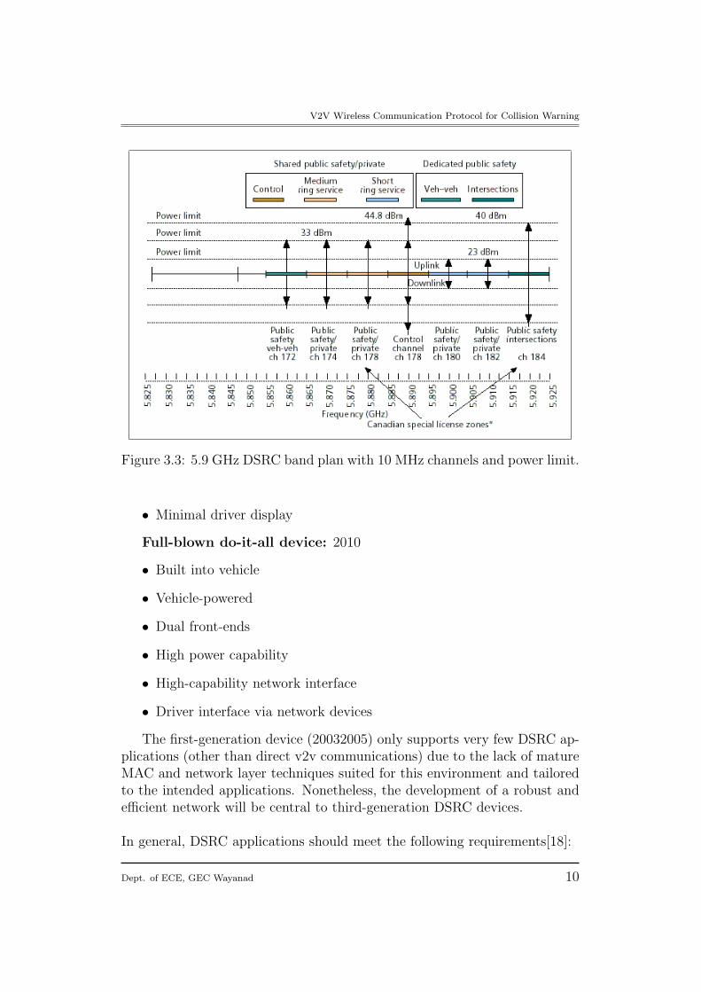
Dedicated Short Range Communications (DSRC) is a block of spectrum inthe 5.850 to 5.925 GHz band allocated by US FCC (Federal Communica-tion Commission) to enhance the safety and the productivity of the trans-portation system with regard to ITS. ASTM (American Society for Testingand Materials) standardization committee E17.51 is working on the devel-opment of a standard. The drawn MAC schemes are mostly following theIEEE 802.11 MAC, and the greater part is deal with the physical layer inOSI. DSRC is a medium range communication service intended to supportboth Public Safety and licensed Private operations over roadside-to-vehicleand vehicle-to-vehicle communication channels. DSRC complements cellularcommunications by providing very high data transfer rates in circumstanceswhere minimizing latency in the communication link and isolating relativelysmall communication zones are important. And Figure 3.3 shows the DSRCspectrum allocation in 5.9 GHz permitted by FCC in 1999. There are threetypes of channels in plan, V2V channel, control channel, and V2R channel.To cater to the emerging wireless communication needs with regard to ve-hicles, in July 2003 ASTM and IEEE adopted the Dedicated Short RangeCommunication (DSRC) standard (ASTM E 2213-03) [17]. The aim of thisstandard is to provide wireless communications capabilities for transporta-tion applications within a 1000m range at typical highway speeds. It providesseven channels at the 5.9 GHz licensed band for ITS applications, with differ-ent channels designated for different applications, including one specificallyreserved for vehicle-to-vehicle communications. The ITS safety applicationsthat could leverage the new DSRC standard include any system that canbe enhanced by allowing information to flow between vehicles and betweenvehicles and roadside infrastructure.
IEEE P1609 Working Group is proposing DSRC as IEEE 802.11p stan-dard. IEEE 802.11p is a standard in the IEEE 802.11 family. IEEE 802.11palso referred to as Wireless Access for the Vehicular Environment (WAVE)defines enhancements to 802.11 required to support Intelligent Transporta-
Dept. of ECE, GEC Wayanad 7
V2V Wireless Communication Protocol for Collision Warning
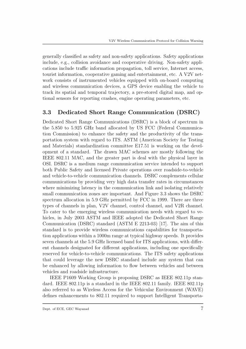
tion Systems (ITS) applications. DSRC is based on IEEE 802.11a.
Bandwidth 75MHz (5.850 5.925GHz)Modulation QPSK OFDMChannels 7 channelsData Rate 1-54MbpsMax Range 1000mMin. Separation 10m
Table 3.1: DSRC Specifications
The extension of the 802.11 MAC layer for DSRC is currently under theIEEE Project P1609.4. The protocol architecture of DSRC is given in Fig 4
Figure 3.2: DSRC Protocol Architecture
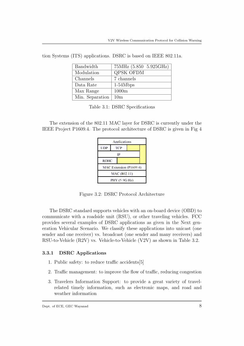
The DSRC standard supports vehicles with an on-board device (OBD) tocommunicate with a roadside unit (RSU), or other traveling vehicles. FCCprovides several examples of DSRC applications as given in the Next gen-eration Vehicular Scenario. We classify these applications into unicast (onesender and one receiver) vs. broadcast (one sender and many receivers) andRSU-to-Vehicle (R2V) vs. Vehicle-to-Vehicle (V2V) as shown in Table 3.2.
3.3.1 DSRC Applications
1. Public safety: to reduce traffic accidents[5]
2. Traffic management: to improve the flow of traffic, reducing congestion
3. Travelers Information Support: to provide a great variety of travel-related timely information, such as electronic maps, and road andweather information
Dept. of ECE, GEC Wayanad 8
V2V Wireless Communication Protocol for Collision Warning
Unicast BroadcastR2V Toll payment,
and road sideinspection
Safety mes-sage,road ser-vice, and travelinformation
V2V Data shar-ing,paging,and VoIP
emergency andservice vehicles
Table 3.2: Different DSRC Appl.
4. Entertainment/rich media content delivery: Internet access, infotain-ment (news, sports, movies, etc.) on demand. Three stages in devel-oping DSRC devices and their respective timeframes were identified asfollows:
Early adopter device: largely self-contained, minimal interface require-ments (for 2003-2005):
• Largely self-contained
• Aftermarket
• Vehicle-powered (a radar detector)
• One front-end
• Moderate power capability
• No network interface
• Minimal driver display (probably separated)
Second-generation device: good feature set without high-cost compo-nents/features (for 2007-2008)
• Built-in and aftermarket versions
• Vehicle-powered
• One or two front-ends
• Moderate power capability
• Possible network interface
Dept. of ECE, GEC Wayanad 9
V2V Wireless Communication Protocol for Collision Warning
Figure 3.3: 5.9 GHz DSRC band plan with 10 MHz channels and power limit.
• Minimal driver display
Full-blown do-it-all device: 2010
• Built into vehicle
• Vehicle-powered
• Dual front-ends
• High power capability
• High-capability network interface
• Driver interface via network devices
The first-generation device (20032005) only supports very few DSRC ap-plications (other than direct v2v communications) due to the lack of matureMAC and network layer techniques suited for this environment and tailoredto the intended applications. Nonetheless, the development of a robust andefficient network will be central to third-generation DSRC devices.
In general, DSRC applications should meet the following requirements[18]:
Dept. of ECE, GEC Wayanad 10
V2V Wireless Communication Protocol for Collision Warning
1. Low Latency: Real-time information should be received by travelingvehicles or RSU with low or minimum latency. If the latency is toolong, the vehicle may be out of the RF range before the communicationis complete.
2. High mobility: Study has shown that signal-to-noise ratio goes up andthroughput goes down as traveling speed increases . As a result, ap-plications in a fixed wireless environment may not work properly in amobile environment. We need to consider the factor of high mobilityin DSRC application development.
3. High reliability: Information from emergency vehicle or RSU has im-pact on public safety, so their reception by the traveling vehicle shouldbe guaranteed.
4 Application Challenges
Even though V2V communication may be beneficial, wireless communicationis typically unreliable. Many factors, for example, channel fading, packetcollisions, and communication obstacles, can prevent messages from beingcorrectly delivered in time. In addition, ad hoc networks formed by nearbyvehicles are quite different from traditional ad hoc networks due to high mo-bility of vehicles. Using V2V communication, when a vehicle on the roadacts abnormally, e.g., deceleration exceeding a certain threshold, dramaticchange of moving direction, major mechanical failure, etc., it becomes anabnormal vehicle(AV). An AV actively generates Emergency Warning Mes-sages (EWMs), which include the geographical location, speed, accelerationand moving direction of the AV, to warn other surrounding vehicles. Areceiver of the warning messages can then determine the relevancy to theemergency based on the relative motion between the AV and itself.
4.1 Challenge 1: Stringent delay requirements imme-diately after the emergency
Over a short period immediately after an emergency event, the faster thewarning is delivered to the endangered vehicles, the more likely accidentscan be avoided. We define EWM delivery delay from an AV A to a vehicle Vas the elapsed duration from the time the emergency occurs at A to the timethe first corresponding EWM message is successfully received by V. Since avehicle moving at the speed of 80 miles/hour can cross more than one meter
Dept. of ECE, GEC Wayanad 11
V2V Wireless Communication Protocol for Collision Warning
in 30ms, the EWM delivery delay for each affected vehicle should be in theorder of milliseconds.
However, the link qualities in V2V communications can be very bad due tomulti path fading, shadowing, and Doppler shifts caused by the high mobilityof vehicles. The performance of a wireless LAN in different vehicular trafficand mobility scenarios is assessed, which shows that the deterioration insignal quality increases with the relative and average velocities of the vehiclesusing 802.11b. Besides unreliable wireless links, packet collisions caused byMAC layer can also contribute to the loss of EWMs.
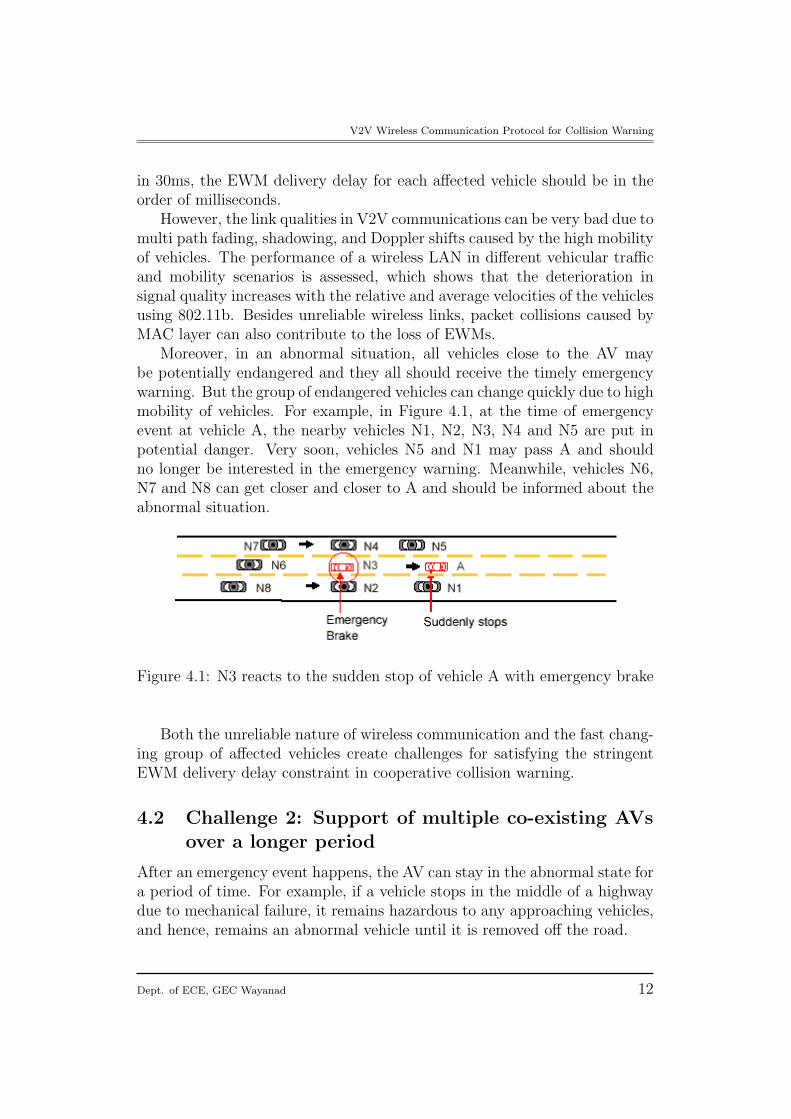
Moreover, in an abnormal situation, all vehicles close to the AV maybe potentially endangered and they all should receive the timely emergencywarning. But the group of endangered vehicles can change quickly due to highmobility of vehicles. For example, in Figure 4.1, at the time of emergencyevent at vehicle A, the nearby vehicles N1, N2, N3, N4 and N5 are put inpotential danger. Very soon, vehicles N5 and N1 may pass A and shouldno longer be interested in the emergency warning. Meanwhile, vehicles N6,N7 and N8 can get closer and closer to A and should be informed about theabnormal situation.
Figure 4.1: N3 reacts to the sudden stop of vehicle A with emergency brake
Both the unreliable nature of wireless communication and the fast chang-ing group of affected vehicles create challenges for satisfying the stringentEWM delivery delay constraint in cooperative collision warning.
4.2 Challenge 2: Support of multiple co-existing AVsover a longer period
After an emergency event happens, the AV can stay in the abnormal state fora period of time. For example, if a vehicle stops in the middle of a highwaydue to mechanical failure, it remains hazardous to any approaching vehicles,and hence, remains an abnormal vehicle until it is removed off the road.
Dept. of ECE, GEC Wayanad 12
V2V Wireless Communication Protocol for Collision Warning
Furthermore, emergency road situations frequently have chain effects.When a leading vehicle applies an emergency brake, it is probable that vehi-cles behind it will react by also decelerating suddenly.
We define co-existing AVs as all the AVs whose existences overlap in timeand whose transmissions may interfere with each other. Due to the fact thatan AV can exist for a relatively long period and because of the chain effectof emergency events, many co-existing AVs can be present.
Therefore, in addition to satisfying stringent delivery delay requirementsof EWMs at the time of emergency events, the vehicular collision warningcommunication protocol has to support a large number of co-existing AVsover a more extended period of time.
4.3 Challenge 3: Differentiation of emergency eventsand elimination of redundant EWMs
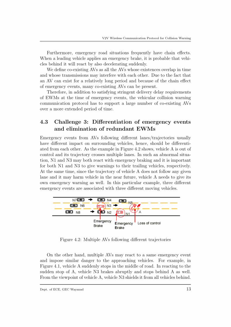
Emergency events from AVs following different lanes/trajectories usuallyhave different impact on surrounding vehicles, hence, should be differenti-ated from each other. As the example in Figure 4.2 shows, vehicle A is out ofcontrol and its trajectory crosses multiple lanes. In such an abnormal situa-tion, N1 and N3 may both react with emergency braking and it is importantfor both N1 and N3 to give warnings to their trailing vehicles, respectively.At the same time, since the trajectory of vehicle A does not follow any givenlane and it may harm vehicle in the near future, vehicle A needs to give itsown emergency warning as well. In this particular example, three differentemergency events are associated with three different moving vehicles.
Figure 4.2: Multiple AVs following different trajectories
On the other hand, multiple AVs may react to a same emergency eventand impose similar danger to the approaching vehicles. For example, inFigure 4.1, vehicle A suddenly stops in the middle of road. In reacting to thesudden stop of A, vehicle N3 brakes abruptly and stops behind A as well.From the viewpoint of vehicle A, vehicle N3 shields it from all vehicles behind.
Dept. of ECE, GEC Wayanad 13
V2V Wireless Communication Protocol for Collision Warning
In such a case, there is no need for A to continue sending redundant EWMssome time after the emergency for several reasons: first, channel bandwidthwould be consumed by unnecessary warning messages; and second, as moresenders contend for a common channel, the delays of useful warning messagesare likely to increase.
In real life, various reactions from drivers can happen. In the example ofFigure 4.1, EWMs from A is redundant as long as N3 stays behind it andsends EWMs. Later on, the driver of N3 may change lane and drive away.When this happens, EWMs from A becomes necessary again if A remainsstopped in the middle of the road. Therefore, the design of collision warningcommunication protocol needs to both take advantage of traffic patterns, andbe robust to complicated road situations and driver behaviors.
5 Vehicular Collision Warning Communica-
tion (VCWC) Protocol Proposal
A vehicle can become an abnormal vehicle (AV) due to its own mechanicalfailure or due to unexpected road hazards. A vehicle can also become anAV by reacting to other AVs nearby. Once an AV resumes it regular move-ment, the vehicle is said no longer an AV and it returns back to the normalstate. In general, the abnormal behavior of a vehicle can be detected usingvarious sensors within the vehicle. Exactly how normal and abnormal sta-tuses of vehicles are detected is beyond the scope of this paper. We assumethat a vehicle controller can automatically monitor the vehicle dynamics andactivate the collision warning communication module when it enters an ab-normal state. A vehicle that receives the EWMs can verify the relevancy tothe emergency event based on its relative motion to the AV, and give audioor visual warnings/advice to the driver.
Each message used in VCWC protocol is intended for a group of receivers,and the group of intended receivers changes fast due to high mobility ofvehicles, which necessitate the message transmissions using broadcast insteadof unicast. To ensure reliable delivery of emergency warnings over unreliablewireless channel, EWMs need to be repeatedly transmitted.
Conventionally, to achieve network stability, congestion control has beenused to adjust the transmission rate based on the channel feedback. If apacket successful goes through, transmission rate is increased; while the rateis decreased if a packet gets lost.
Unlike conventional congestion control, here, there is no channel feed-back available for the rate adjustment of EWMs due to the broadcast nature
Dept. of ECE, GEC Wayanad 14
V2V Wireless Communication Protocol for Collision Warning
of EWM transmissions. Instead, we identify more application-specific prop-erties to help EWM congestion control, which consists of the EWM trans-mission rate adjustment algorithm and the state transition mechanism forAVs.
This paper also focuses on Congestion Control Policies; the proposedVCWC protocol also includes emergency warning dissemination methodsthat make use of both natural response of human drivers and EWM messageforwarding, and a message differentiation mechanism that enables coopera-tive vehicular collision warning application to share a common channel withother non-safety related applications.
5.1 Assumptions
We first clarify related assumptions we have made for each vehicle partici-pating in the cooperating collision warning.
• Such a vehicle is able to obtain its own geographical location, anddetermine its relative position on the road (e.g., the road lane it is in).One possibility is that, the vehicle is equipped with a Global PositionSystem (GPS) or Differential Global Position System (DGPS) receiverto obtain its geographical position, and it may be equipped with adigital map to determine which lane it is in.
• Such a vehicle is equipped with at least one wireless transceiver, andthe vehicular ad hoc networks are composed of vehicles equipped withwireless transceivers.
• As suggested by DSRC, the transmission range of safety related vehicle-to-vehicle messages is assumed to be 300m (in early stage), and channelcontention is resolved using IEEE 802.11 DCF based multi-access con-trol.
5.2 State Transitions of AVs
The objective of the state transition mechanism is to ensure EWM cover-age for the endangered regions and to eliminate redundant EWMs, whileincurring little control overhead.
Each AV may be in one of three states, initial AV, non-flagger AV andflagger AV. When an emergency event occurs to a vehicle, the vehicle be-comes an AV and enters the initial AV state, transmitting EWMs followingthe Rate Decreasing Algorithm described in Section 4.2 of [2]. An initial AVcan become a non-flagger AV, refraining from sending EWMs contingent on
Dept. of ECE, GEC Wayanad 15
V2V Wireless Communication Protocol for Collision Warning
some conditions to eliminate redundant EWMs. In some road situations, itis necessary for a non-flagger AV to become a flagger AV, resuming EWMtransmissions at the minimum required rate.
1. At least Talert duration has elapsed since the time when the vehiclebecame an initial AV. As EWMs have been repeatedly transmittedover Talert duration, by then, the vehicles having been close to the AVshould have received the emergency warning with high probability.
2. EWMs from one of the “followers” of the initial AV are being overheard;here, we define vehicle X as a “followers” of vehicle Y, if X is locatedbehind Y in the same lane and any vehicle endangered by Y may alsobe endangered by X.
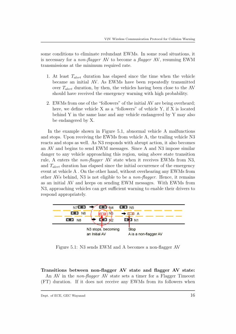
In the example shown in Figure 5.1, abnormal vehicle A malfunctionsand stops. Upon receiving the EWMs from vehicle A, the trailing vehicle N3reacts and stops as well. As N3 responds with abrupt action, it also becomesan AV and begins to send EWM messages. Since A and N3 impose similardanger to any vehicle approaching this region, using above state transitionrule, A enters the non-flagger AV state when it receives EWMs from N3,and Talert duration has elapsed since the initial occurrence of the emergencyevent at vehicle A . On the other hand, without overhearing any EWMs fromother AVs behind, N3 is not eligible to be a non-flagger. Hence, it remainsas an initial AV and keeps on sending EWM messages. With EWMs fromN3, approaching vehicles can get sufficient warning to enable their drivers torespond appropriately.
Figure 5.1: N3 sends EWM and A becomes a non-flagger AV
Transitions between non-flagger AV state and flagger AV state:An AV in the non-flagger AV state sets a timer for a Flagger Timeout
(FT) duration. If it does not receive any EWMs from its followers when
Dept. of ECE, GEC Wayanad 16
V2V Wireless Communication Protocol for Collision Warning
the FT timer expires, the non-flagger AV changes its state to flagger AV.Otherwise; it simply resets the FT timer and repeats above procedures. Ifa flagger AV receives EWMs from one of its followers, it will relinquish itsflagger responsibility, becoming a non flagger AV.
A flagger AV transmits EWMs at the minimum rate λmin since a vehi-cle can only become a flagger AV some time after the emergency. Observethat, at the time when an emergency occurs, the emergency warning needsto be delivered to all surrounding vehicles as soon as possible because theendangered vehicles can be very close to the AV. After a while, however,the nearby vehicles should have received the emergency warnings with highprobability. What matters then is to give emergency warnings to approach-ing vehicles that just enter the transmission range of the AV. Therefore, thevalue of λmin is mainly determined by the radio transmission range, max-imum speed, deceleration capability of vehicles and channel conditions. Ifradio transmission range is large enough, an approaching vehicle can toleratea relatively long delivery delay. For example, in Figure 5.1, N6 enters thetransmission range of A some time after the emergency event. If we assumethat the transmission range is 300 meters,(in early cases), then one or twosecond delay in receiving the emergency warning for N6 should not causemuch negative impact.
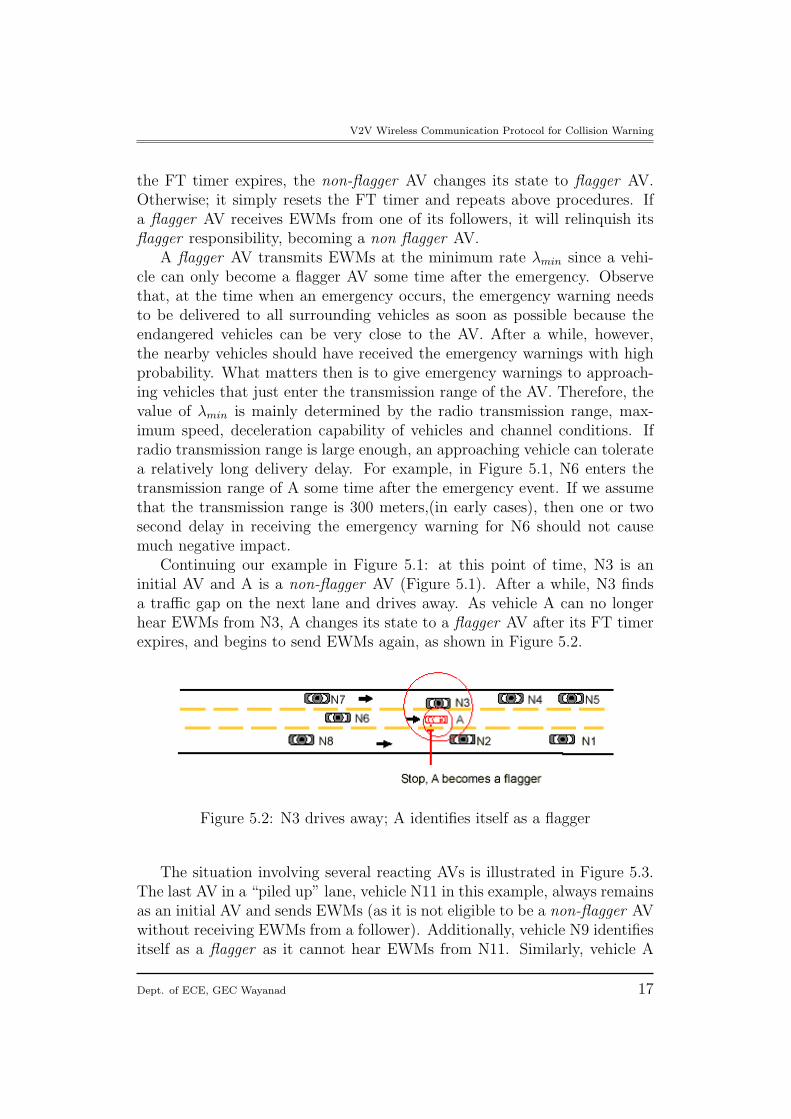
Continuing our example in Figure 5.1: at this point of time, N3 is aninitial AV and A is a non-flagger AV (Figure 5.1). After a while, N3 findsa traffic gap on the next lane and drives away. As vehicle A can no longerhear EWMs from N3, A changes its state to a flagger AV after its FT timerexpires, and begins to send EWMs again, as shown in Figure 5.2.
Figure 5.2: N3 drives away; A identifies itself as a flagger
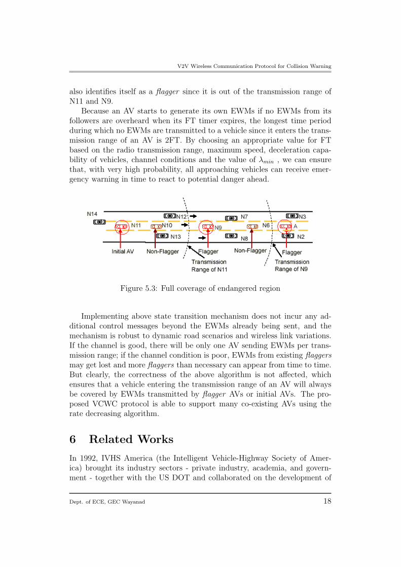
The situation involving several reacting AVs is illustrated in Figure 5.3.The last AV in a “piled up” lane, vehicle N11 in this example, always remainsas an initial AV and sends EWMs (as it is not eligible to be a non-flagger AVwithout receiving EWMs from a follower). Additionally, vehicle N9 identifiesitself as a flagger as it cannot hear EWMs from N11. Similarly, vehicle A
Dept. of ECE, GEC Wayanad 17
V2V Wireless Communication Protocol for Collision Warning
also identifies itself as a flagger since it is out of the transmission range ofN11 and N9.
Because an AV starts to generate its own EWMs if no EWMs from itsfollowers are overheard when its FT timer expires, the longest time periodduring which no EWMs are transmitted to a vehicle since it enters the trans-mission range of an AV is 2FT. By choosing an appropriate value for FTbased on the radio transmission range, maximum speed, deceleration capa-bility of vehicles, channel conditions and the value of λmin , we can ensurethat, with very high probability, all approaching vehicles can receive emer-gency warning in time to react to potential danger ahead.
Figure 5.3: Full coverage of endangered region
Implementing above state transition mechanism does not incur any ad-ditional control messages beyond the EWMs already being sent, and themechanism is robust to dynamic road scenarios and wireless link variations.If the channel is good, there will be only one AV sending EWMs per trans-mission range; if the channel condition is poor, EWMs from existing flaggersmay get lost and more flaggers than necessary can appear from time to time.But clearly, the correctness of the above algorithm is not affected, whichensures that a vehicle entering the transmission range of an AV will alwaysbe covered by EWMs transmitted by flagger AVs or initial AVs. The pro-posed VCWC protocol is able to support many co-existing AVs using therate decreasing algorithm.
6 Related Works
In 1992, IVHS America (the Intelligent Vehicle-Highway Society of Amer-ica) brought its industry sectors - private industry, academia, and govern-ment - together with the US DOT and collaborated on the development of
Dept. of ECE, GEC Wayanad 18
V2V Wireless Communication Protocol for Collision Warning
a Strategic Plan for IVHS in the United States. The plan clearly noted“as development proceeds, there will be increasing interaction among trafficmanagement, traveler information, and vehicle control systems.” In 1995,the newly-renamed ITS America again collaborated with the US DOT onthe development of a National ITS Program Plan that clearly visualized in-tersection collision avoidance applications that “may involve infrastructure-to-vehicle and/or vehicle-to vehicle communications.”
Six years later in 2001, ITS America and the US DOT came together yetagain, and began to lay the groundwork for the future in the developmentof a new strategic document, the National ITS Program Plan: A Ten-YearVision. This Plan outlined an enabling path to collision avoidance ”throughthe use of dedicated short-range communications to support infrastructure-vehicle and vehicle-vehicle communications,” particularly in the 5.9GHz bandallocated by the Federal Communications Commission (at the request of ITSAmerica) for ITS safety applications.
ITS Program recently re-organized into many areas; some of them areIntegrated Vehicle Based Safety Systems, Cooperative Intersection CollisionAvoidance Systems, Vehicle Infrastructure Integration (VII) etc... Each hasits own goal, vision and deployment method. Their goals are respectively, allnew vehicles equipped with advanced driver assistance systems to help driversavoid the most common types of deadly crashes; Achieve deployment of inter-section collision avoidance systems at 15% of the most hazardous signalizedintersections nationally, with in-vehicle support in 50% of the vehicle fleetby 2015. Also nationwide deployment of a communications infrastructureon roadways and in all production vehicles to enable a number of key safetyand operational services (ie VII). For that, the vehicle manufacturers wouldinstall the technology in all new vehicles, beginning at a particular modelyear; at the same time, federal/state/local transportation agencies would fa-cilitate installation of a roadside communications infrastructure. Again theassumption is that decisions about full-scale deployment in both the vehiclesand the infrastructure will need to be made in the 2008/9 timeframe.
To determine the feasibility and an implementation strategy, a three-partyconsortium has been formed consisting of the seven vehicle manufacturers,AASHTO (American Association of State Highway and Transportation Of-ficials) ten State departments of transportation and the USDOT.
There are many projects related to communication networks among road-users. FleetNet and CarTALK 2000 are some of them. FleetNet is a Germanproject for Internet on the road and is about an ad-hoc radio network forinter-vehicle communications. Among the participants, we find Siemens,NEC, Bosch, DaimlerChrysler, and three German universities. They plan touse the UTRA TDD radio hardware. UTRA TDD is one of the 3G systems
Dept. of ECE, GEC Wayanad 19
V2V Wireless Communication Protocol for Collision Warning
defined by ITU. From the information available about the project, it appearsthat the FleetNet system (like many others) is more about connecting vehiclesto internet and not that much to avoid traffic accidents, which will not bepossible by using UTRA TDD.
CarTALK 2000 is an EU-IST funded project in the fifth framework pro-gram, started August 2001 and funded for three years. It is focusing on newdriver assistance systems which are based upon inter-vehicle communication.The main objectives are the development of co-operative driver assistancesystems and the development of a self-organizing ad-hoc radio network as acommunication basis with the aim of preparing a future standard.
The European Commission is funding several projects under the so-calledeSafety initiative launched in 2002 in order to halve the number of roadfatalities by 2010 (in 2005 40,000 persons were killed and 1.8 million severelyinjured in the sole European Union). Another incentive is the desire to limittraffic congestion and thus to optimize road density and the number of peoplein a given vehicle. Yet another one is consumption, which is indeed a functionof the traffic congestion and advanced itinerary planning. All of these are themotivations behind Intelligent Car, one of the European Information Society2010 (i2010) Flagship initiatives adopted in February 2005.
The Car2Car Communication Consortium (C2C-CC) is a non-profit or-ganisation initiated by European vehicle manufacturers, which is open forsuppliers, research organisations and other partners. The Car2Car Commu-nication Consortium is dedicated to the objective of further increasing roadtraffic safety and efficiency by means of inter-vehicle communications. Themission and the objectives of the Car2Car Communication Consortium areto create and establish an open European industry standard for Car2Carcommunication systems based on wireless LAN components and to guar-antee European-wide inter-vehicle operability,to enable the development ofactive safety applications by specifying, prototyping and demonstrating theCar2Car system, to promote the allocation of a royalty free European wideexclusive frequency band for Car2Car applications etc...
Dept. of ECE, GEC Wayanad 20
V2V Wireless Communication Protocol for Collision Warning
7 Conclusion
This paper shows an Overview of different vehicular communication with re-gard to Intelligent Transportation System, also the Vehicle to Vehicle (V2V)communication using DSRC Standard is described. This paper also discussedsome of the application challenges and proposes a new protocol which pro-vides congestion control polices. This protocol defines congestion controlpolicies for emergency warning messages so that a low emergency warningmessage delivery delay can be achieved and a large number of co-existing ab-normal vehicles can be supported. It also introduces a method to eliminateredundant emergency warning messages, exploiting the natural chain effectof emergency events.
ROAD SAFETY Benefits for all actors
Drivers: will drive vehicles equipped with more robust driving assis-tance systems thanks to dynamic information about the traffic, the road andthe environmental conditions from the vehicle net and from the infrastruc-ture.
Car makers: will open new market opportunities offering on the mar-ket new functions for safer vehicles at sustainable costs as the ’intelligence’will be distributed. The level of complexity of vehicles will be decreased,compared to autonomous solutions.
Suppliers: will meet the challenge of new market opportunities beingready to offer fully developed technical solutions and actively driving theevolution in terms of concept generation, and standardisation.
Road operators and public authorities: will improve road safetyon motorways and urban roads via a combination of infrastructure and ve-hicle systems that will collect and transmit in real time traffic/weather andaccident information to all road users and to traffic information centers.
Wireless in-vehicle network technologies and protocols have the potentialto support many new and innovative applications. These applications arebased on intra-vehicle, vehicle-to-vehicle, and vehicle-to-roadside networkingof in-vehicle systems and devices. These technologies can greatly enhancethe infotainment, telematics, safety, comfort, and convenience value of newvehicles. A new era is arriving where vehicles will communicate with each
Dept. of ECE, GEC Wayanad 21
V2V Wireless Communication Protocol for Collision Warning
Figure 7.1: In the mere future,we can expect cars talking each other
other, the devices within them, and also with the world; making the nextgeneration of vehicles into communication hubs.
•
Dept. of ECE, GEC Wayanad 22
References
[1] S Biswas, “Vehicle-to-Vehicle Wireless Communication Protocols for En-hancing Highway Traffic Safety”,Communications Magazine, IEEE Pub-lication Date: Jan. 2006 Volume: 44, Issue: 1 page(s):74- 82
[2] X. Yang et al., “A Vehicle-to-Vehicle Communication Protocol for Co-operative Collision Warning”, Proc. 1st Annual Intl. Conf. Mobile andUbiquitous Syst: Networking and Services, 2004.
[3] G.S Bickel, “Inter/Intra-Vehicle Wireless Communication” also availableat http://userfs.cec.wustl.edu/~gsb1/index.html
[4] Q. Xu, R. Sengupta, and D. Jiang, “Design and Analysis of HighwaySafety Communication Protocol in 5.9 GHz Dedicated Short-Range Com-munication Spectrum”, Proc. IEEE VTC, vol. 57, no. 4, 2003, pp. 245155.
[5] J. Zhu and S. Roy, “MAC for Dedicated Short Range Communicationsin Intelligent Transport Systems”, IEEE Commun. Mag., vol. 41, no. 12,2003.
[6] C.Bettstetter “Toward Internet-Based Car Communications: On SomeSystem Architecture And Protocol Aspects” Inst. of Comm. NetworksTUM, Germany
[7] A.Svensson, Fellow, IEEE, “A Communication Network for Safe Traf-fic and Efficient Transportation” Dept. of Sig. & Sys, Chalmers Uni.ofTech,Swedan
[8] L.Iftode, C. Borcea, N. Ravi, T .Nadeem “Exploring the Design andImplementation of Vehicular Networked Systems”
[9] MD Dikaiakos, S. Iqbal, T. Nadeem, L. Iftode “VITP: An InformationTransfer Protocol for Vehicular Computing”
23
V2V Wireless Communication Protocol for Collision Warning
[10] Dashtinezhad, T.Nadeem, C.Borcea, B.Dorohonceanu “Traffic View: ADriver Assistant Device for Traffic Monitoring based on Car-to-Car Com-munication”
[11] H Wu, “Analysis and Design of Vehicular Networks” ,Georgia Inst. ofTech, Oct. 30,2004
[12] J.-H. Li, C.-H. Chang, and Y.-H. Chan “MAC (Media Access Control)Design and Implementation of DSRC (Dedicated Short Range Commu-nication) Systems”
[13] “India’s accident record among the worst in the world” Online Editionof newspaper ‘Deccan Herald’ , Wednesday, February 16, 2005
[14] National Center for Statistics and Analysis, “Traffic Safety Facts 2003,”Report DOT HS 809 767, Natl. Highway Traffic Safety Admin., U.S.DOT, Washington, DC, 2004.
[15] C. D. Wang and J. P. Thompson. “Apparatus and method for motiondetection and tracking of objects in a region for collision avoidance utiliz-ing a real-time adaptive probabilistic neural network”, 1997. US.PatentNo. 5,613,039.
[16] M. Green. “How Long Does It Take to Stop?” Methodological Anal-ysis of Driver Perception-Brake Times. Transportation Human Factors,2(3):195-216, 2000.
[17] ASTM E2213-03, “Standard Specification for Telecommunications andInformation Exchange Between Roadside and Vehicle Systems - 5 GHzBand Dedicated Short Range Communications (DSRC) Medium AccessControl (MAC) and Physical Layer (PHY) Specifications,” ASTM Intl.,July 2003.
[18] James T. Yu, “Requirements Analysis of IP and MAC Protocols forDedicated Short Range Communications (DSRC)”, School of Comp. Sc.,De Paul University.
[19] http://www.car-to-car.org
[20] http://www.leearmstrong.com/DSRC/DSRCHomeset.htm
Dept. of ECE, GEC Wayanad 24
Appendix
1 Abbreviation
AASHTO American Association of State Highway and Transportation OfficialsASTM American Society for Testing and MaterialsAV Abnormal VehicleDCF Distributed Coordination FunctionDGPS Differential GPSDSRC Dedicated Short Range CommunicationETC Electronic Toll CollectionEWM Emergency Warning Message.FCC Federal Communications CommissionGPS Global Positioning SystemISM Industry, Science, and MedicineITS Intelligent Transportation SystemsITU International Telecommunication UnionIVC Inter-Vehicle CommunicationMAC Medium Access ControlOBD On-Board DeviceOFDM Orthogonal Frequency division multiplexingOSI Open Systems InterconnectionRSU Road Side UnitTDD Time Division DuplexUS DOT United States Department of TransportationUTRA Universal Terrestrial Radio AccessUWB Ultra-Wide BandV2R Vehicle to RoadsideV2V Vehicle to VehicleVCWC Vehicular Collision Warning CommunicationWAVE Wireless Access in the Vehicular Environment
25


![Test Optimization for Core-based System-on-Chip113594/FULLTEXT01.pdf · ITRS 1999 [Sem99] and ITRS 2001 [Sem01], and shows how the relative cost of test grows compared to the fabrication](https://img.pdfslide.us/doc/110x75/5ed82f050fa3e705ec0dfddc/test-optimization-for-core-based-system-on-113594fulltext01pdf-itrs-1999-sem99.jpg)