Embed Size (px)
Citation preview

Australian Design Rule 59/00 Standards For Omnibus Rollover Strength 1
Vehicle Standard (Australian Design Rule 59/00 –
Standards For Omnibus Rollover Strength) 2007
Compilation: 1 (up to and including Vehicle Standard (Australian Design Rule
59/00 – Standards For Omnibus Rollover Strength) 2007
Amendment 1)
Compilation Date: 19/07/2012
Compiled by: Vehicle Safety Standards, Department of Infrastructure and
Transport
Federal Register of Legislative Instruments F2012C00535

Australian Design Rule 59/00 Standards For Omnibus Rollover Strength 2
CONTENTS
1. LEGISLATIVE PROVISIONS .......................................................................... 3
2. FUNCTION & SCOPE ...................................................................................... 3
3. APPLICABILITY .............................................................................................. 3
4. DEFINITIONS ................................................................................................... 4
5. REQUIREMENTS ............................................................................................. 5
6. EXEMPTIONS AND ALTERNATIVE PROCEDURES ................................. 5
7. ALTERNATIVE STANDARDS ....................................................................... 5
8. NOTES ............................................................................................................... 5
APPENDIX A .................................................................................................................. 6
APPENDIX B ................................................................................................................. 65
COMPILATION NOTES ............................................................................................... 76
Federal Register of Legislative Instruments F2012C00535

Australian Design Rule 59/00 Standards For Omnibus Rollover Strength
3
1. LEGISLATIVE PROVISIONS
1.1. Name of Standard
1.1.1. This Standard is the Vehicle Standard (Australian Design Rule 59/00 –
Standards For Omnibus Rollover Strength) 2007.
1.1.2. This Standard may also be cited as Australian Design Rule 59/00 —
Standards For Omnibus Rollover Strength.
1.2. Commencement
1.2.1. This Standard commences on the day after it is registered.
1.3. Repeal
1.3.1. This Standard repeals and replaces Vehicle Standard (Australian Design
Rule 59/00 – Standards For Omnibus Rollover Strength) 2006
2. FUNCTION & SCOPE
The function of this vehicle standard is to ensure that omnibus
superstructures withstand forces encountered in rollover crashes so as to
maintain a residual space during and after a rollover crash.
3. APPLICABILITY
This vehicle standard applies to the design and construction of vehicles
as set out in clause 3.4.
3.1. This standard applies to single-deck, rigid or articulated vehicles
constructed for the carriage of more than 16 passengers, whether seated
or standing, in addition to the driver and crew.
3.2. * ME category vehicle ‘Route Service Omnibuses’ need not comply with
this rule until 1 July 1993.
3.3. Omnibuses are not required to comply with this rule if the following
percentages of the area of the upper surface of the floor measured
between its ‘Axles’, is not more than 550 mm above the ground:
For a wheel base: 6.5 metres and over 75%
less than 6.5 metres 70%
less than 6.0 metres 65%
less than 5.5 metres 60%
less than 5.0 metres 55%
less than 4.5 metres 50%
The floor height of 550 mm is measured at the ‘Suspension Height’
corresponding to the ‘Unladen Mass’ of the vehicle.
Federal Register of Legislative Instruments F2012C00535

Australian Design Rule 59/00 Standards For Omnibus Rollover Strength
4
3.4. Applicability Table
Vehicle Category
ADR
Category
Code *
UNECE
Category
Code *
Manufactured
on or After
Acceptable
Prior Rules
Moped 2 wheels LA L1 N/A
Moped 3 wheels LB L2 N/A
Motor cycle LC L3 N/A
Motor cycle and sidecar LD L4 N/A
Motor tricycle LE L5 N/A
LEM N/A
LEP N/A
LEG N/A
Passenger car MA M1 N/A
Forward-control passenger vehicle MB M1 N/A
Off-road passenger vehicle MC M1 N/A
Light omnibus MD M2
up to 3.5 tonnes ‗GVM’ and up to 12
seats
MD1 N/A
up to 3.5 tonnes ‘GVM’ and more
than 12 seats
MD2 1 July 1993 Nil
over 3.5 tonnes and up to 4.5 tonnes
‘GVM’
MD3 1 July 1993 Nil
over 4.5 tonnes and up to 5 tonnes
‘GVM’
MD4 1 July 1993 Nil
Heavy omnibus ME M3 1 July 1992* Nil
Light goods vehicle NA N1 N/A
Medium goods vehicle NB N2 N/A
over 3.5 tonnes up to 4.5 tonnes
‘GVM’
NB1 N/A
over 4.5 tonnes up to 12 tonnes
‘GVM’
NB2 N/A
Heavy goods vehicle NC N3 N/A
Very light trailer TA O1 N/A
Light trailer TB O2 N/A
Medium trailer TC O3 N/A
Heavy trailer TD O4 N/A
4. DEFINITIONS
4.1. For vehicle categories, definitions and meanings used in this standard, refer
to:
4.2. Definitions in Section 2 of Appendix A of this standard or Section 2 of the
alternative standard at clause 7;
4.3. Definitions in Clause 1 of Appendix B; and where there is no conflict
* The category code may also be in the format L1, LA etc.
Federal Register of Legislative Instruments F2012C00535

Australian Design Rule 59/00 Standards For Omnibus Rollover Strength
5
4.4. Vehicle Standard (Australian Design Rule Definitions and Vehicle
Categories) 2005.
5. REQUIREMENTS
5.1 Vehicles of applicable categories listed in clause 3.4 must comply with this
standard by meeting the requirements of either Appendix A, as varied by
section 6 Exemptions and Alternative Procedures or Appendix B.
5.2 Appendix B is a modified extract of the technical provisions of UNECE
R66/00 standard.
6. EXEMPTIONS AND ALTERNATIVE PROCEDURES
6.1 Compliance with the following parts, sections and annexes of Appendix A
is not required or is to be modified for the purposes of this standard.
Scope Paragraph 1.1 is not applicable
Section 3 Application for Approval
Section 4 Approval
Section 6 Modification and extension of approval of a vehicle type
Section 7 Conformity of Production
Section 8 Penalties for non conformity of production
Section 9 Production definitely discontinued
Section 10 Transitional Provisions
Section 11 Names and addresses of technical services responsible for
conducting approval tests, and of administrative departments
Annex 1 Communication concerning the approval or refusal or
extension or withdrawal of production definitely
discontinued of a vehicle type with regards to the strength of
its strength if it superstructure pursuant to regulation No. 66
Annex 2 Arrangements of the approval mark
7. ALTERNATIVE STANDARDS
The technical requirements adopted by the United Nations – Economic
Commission for Europe Regulation No. 66 – UNIFORM TECHNICAL
PRESCRIPTIONS CONCERNING THE APPROVAL OF LARGE
PASSENGER VEHICLES WITH REGARD TO THE STRENGTH OF
THEIR SUPERSTRUCTURE, from the edition incorporating the 00 series
of amendments up to and including the edition incorporating the 02 series
of amendments shall be deemed to be equivalent to the technical
requirements of this standard.
8. NOTES
8.1 Where ‗Technical Services‘ is noted in Appendix A read ‗Test Facility‘.
Federal Register of Legislative Instruments F2012C00535

Australian Design Rule 59/00 Standards For Omnibus Rollover Strength
Appendix A – UNECE R 66/02
6
APPENDIX A
AGREEMENT
CONCERNING THE ADOPTION OF UNIFORM TECHNICAL PRESCRIPTIONS
FOR WHEELED VEHICLES, EQUIPMENT AND PARTS WHICH CAN BE FITTED
AND/OR BE USED ON WHEELED VEHICLES AND THE CONDITIONS FOR
RECIPROCAL RECOGNITION OF APPROVALS GRANTED ON THE BASIS OF
THESE PRESCRIPTIONS */
(Revision 2, including the amendments which entered into force on 16 October 1995)
_________
Addendum 65 : Regulation No. 66
Revision 1
Incorporating all valid text up to:
Supplement 1 to the original version of the Regulation - Date of entry into force: 3 September 1997
01 series of amendments - Date of entry into force: 9 November 2005
and the following amendments included by the Department of Infrastructure and Transport:
Erratum to the 01 series of amendments;
Corrigendum 1 to the 01 series of amendments, subject of Depositary Notification C.N.1151.2006
TREATIES-1 dated 13 December 2006;
Corrigendum 2 to the 01 series of amendments, subject of Depositary Notification C.N.553.2007
TREATIES-1 dated 10 May 2007;
Supplement 1 to the series 01 of the Regulation - Date of entry into force: 15 October 2008
02 series of amendments to the Regulation: Date of entry into force: 19 August 2010
UNIFORM TECHNICAL PRESCRIPTIONS CONCERNING THE APPROVAL OF
LARGE PASSENGER VEHICLES WITH REGARD TO THE STRENGTH OF THEIR
SUPERSTRUCTURE
_________
UNITED NATIONS
*/
Former title of the Agreement:
Agreement Concerning the Adoption of Uniform Conditions of Approval and Reciprocal Recognition of Approval for Motor
Vehicle Equipment and Parts, done at Geneva on 20 March 1958.
Federal Register of Legislative Instruments F2012C00535

Australian Design Rule 59/00 Standards For Omnibus Rollover Strength
Appendix A – UNECE R 66/02
7
Regulation No. 66
UNIFORM TECHNICAL PRESCRIPTIONS CONCERNING THE APPROVAL OF LARGE
PASSENGER VEHICLES WITH REGARD TO THE STRENGTH OF THEIR
SUPERSTRUCTURE
CONTENTS
REGULATION
1. Scope
2. Terms and Definitions
3. Application for approval
4. Approval
5. General specifications and requirements
6. Modification and extension of approval of a vehicle type
7. Conformity of production
8. Penalties for non-conformity of production
9. Production definitely discontinued
10. Transitional provisions
11. Names and addresses of technical services
responsible for conducting approval tests,
and of administrative departments
ANNEXES
Annex 1 - Communication concerning vehicle type with regard to the strength of its
superstructure, pursuant to Regulation No. 66
Annex 2 - Arrangement of the approval mark
Annex 3 - Determination of the centre of gravity of the vehicle
Federal Register of Legislative Instruments F2012C00535

Australian Design Rule 59/00 Standards For Omnibus Rollover Strength
Appendix A – UNECE R 66/02
8
CONTENTS (continued)
Annex 4 - Viewpoints on the structural description of the superstructure
Annex 5 - Rollover test as the basic approval method
Annex 6 - Rollover test using body sections as an equivalent approval method
Annex 7 - Quasi-static loading test of body sections as an equivalent approval method
Appendix 1 – Determination of the vertical movement of the centre of gravity
during rollover
Annex 8 - Quasi-static calculation based on testing of components as an equivalent approval
method
Appendix 1 – Characteristics of plastic hinges
Annex 9 - Computer simulation of rollover test on complete vehicle as an equivalent approval
method
Federal Register of Legislative Instruments F2012C00535

Australian Design Rule 59/00 Standards For Omnibus Rollover Strength
Appendix A – UNECE R 66/02
9
1. SCOPE
1.1 This Regulation applies to single-deck rigid or articulated vehicles belonging to
categories M2 or M3, Classes II or III or class B having more than 16 passengers 1/.
1.2 At the request of the manufacturer, this Regulation may also apply to any other M2 or
M3 vehicle that is not included in paragraph 1.1.
2. TERMS AND DEFINITIONS
For the purposes of this Regulation, the following terms and definitions are used:
2.1. Units of measurement
The units of measurement shall be:
Dimensions and linear distances metres (m) or millimetres (mm)
Mass or load kilograms (kg)
Force (and weight) Newtons (N)
Moment Newton-metres (Nm)
Energy Joules (J)
Gravitational constant 9.81 ( m/s2)
2.2. "Vehicle" means a bus or coach designed and equipped for transportation of
passengers. The vehicle is an individual representative of a vehicle type.
2.3. "Vehicle type" means a category of vehicles produced with the same design technical
specification, main dimensions and constructional arrangement. The vehicle type
shall be defined by the vehicle manufacturer.
2.4. "Group of vehicle types" means those vehicle types, proposed in future as well as
existing now, which are covered by the approval of the worst case, in respect of this
Regulation.
2.5 "Double deck vehicle" means a vehicle where the provided spaces for passengers are
arranged, at least in one part, in two superimposed levels and spaces for standing
passengers are not provided in the upper deck.
2.6. "Worst case" means the vehicle type, among a group of vehicle types, least likely to
withstand the requirements of this Regulation in respect of the strength of
superstructure. The three parameters which define the worst case are: structural
strength, reference energy and the residual space.
1/ As defined in Annex 7 to the Consolidated Resolution on the Construction of vehicles (R.E.3), (document
TRANS/WP.29/78/Rev.1/Amend.2 as last amended by Amend.4).
Federal Register of Legislative Instruments F2012C00535
Australian Design Rule 59/00 Standards For Omnibus Rollover Strength
Appendix A – UNECE R 66/02
10
2.7. "Approval of a vehicle type" means the whole official process in which the vehicle
type is checked and tested to prove that it meets all the requirements specified in this
Regulation.
2.8 "Extension of approval" means the official process in which a modified vehicle type is
approved on the basis of an earlier approved vehicle type, by comparison of structure,
potential energy and residual space criteria.
2.9. "Articulated vehicle" means a vehicle which consists of two or more rigid sections
which articulate to one another, the passenger compartments of each section
intercommunicate so that passengers can move freely between them; the rigid sections
are permanently connected so that they can only be separated by an operation
involving facilities which are normally only found in a workshop.
2.10. "Passenger compartment(s)" means the space(s) intended for passengers‘ use
excluding any space occupied by fixed appliances such as bars, kitchenettes or toilets.
2.11. "Driver's compartment" means the space intended for the driver's exclusive use and
containing the driver's seat, the steering wheel, controls, instruments and other devices
necessary for driving the vehicle.
2.12. "Occupant restraint" means any device which connects a passenger, driver or crew
member to his seat, during a rollover.
2.13. "Vertical longitudinal central plane" (VLCP) means the vertical plane which passes
through the mid-points of the front axle track and the rear axle track.
2.14. "Residual space" means a space to be preserved in the passengers', crew and driver's
compartment(s) to provide better survival possibility for passengers, driver and crew
in case of a rollover accident.
2.15. "Unladen kerb mass" (Mk) means the mass of the vehicle in running order, unoccupied
and unladen but with the addition of 75 kg for the mass of the driver, the mass of fuel
corresponding to 90 per cent of the capacity of the fuel tank specified by the
manufacturer, and the masses of coolant, lubricant, tools and spare wheel, if any.
2.16. "Total occupant mass" (Mm) means the combined mass of any passengers, crew who
occupy seats fitted with occupant restraints.
2.17. "Total effective vehicle mass" (Mt) means the unladen kerb mass of the vehicle (Mk)
combined with the portion (k = 0.5), of the total occupant mass (Mm), considered to be
rigidly attached to the vehicle.
2.18. "Individual occupant mass" (Mmi) means the mass of an individual occupant. The
value of this mass is 68 kg.
Federal Register of Legislative Instruments F2012C00535

Australian Design Rule 59/00 Standards For Omnibus Rollover Strength
Appendix A – UNECE R 66/02
11
2.19. "Reference energy" (ER) means the potential energy of the vehicle type to be
approved, measured in relation to the horizontal lower level of the ditch, at the
starting, unstable position of the rollover process.
2.20. "Rollover test on a complete vehicle" means a test on a complete, full-scale vehicle to
prove the required strength of the superstructure.
2.21. "Tilting bench" means a technical device, an arrangement of tilting platform, ditch and
concrete ground surface, used in the rollover testing of a complete vehicle or body
sections.
2.22. "Tilting platform" means a rigid plane which can be rotated around a horizontal axis
in order to tilt a complete vehicle or body section.
2.23. "Body work" means the complete structure of the vehicle in running order, including
all the structural elements which form the passenger compartment(s), driver's
compartment, baggage compartment and spaces for the mechanical units and
components.
2.24. "Superstructure" means the load-bearing components of the bodywork as defined by
the manufacturer, containing those coherent parts and elements which contribute to
the strength and energy absorbing capability of the bodywork, and preserve the
residual space in the rollover test.
2.25 "Bay" means a structural section of the superstructure forming a closed loop between
two planes which are perpendicular to the vertical longitudinal central plane of the
vehicle.
A bay contains one window (or door) pillar on each side of the vehicle as well as side
wall elements, a section of the roof structure and a section of the floor and underfloor
structure.
2.26. "Body section" means a structural unit, which represents one part of the superstructure
for the purposes of an approval test. A body section contains at least two bays
connected by representative connecting elements (side, roof, and underfloor,
structures).
2.27. "Original body section" means a body section composed of two or more bays of
exactly the same form and relative position, as they appear in the actual vehicle. All
connecting elements between the bays are also arranged exactly as they appear in the
actual vehicle.
2.28. "Artificial body section" means a body section built up from two or more bays but not
in the same position, nor at the same distance from each other as in the actual vehicle.
The connecting elements between these bays need not be identical with the real body
work structure but shall be structurally equivalent.
Federal Register of Legislative Instruments F2012C00535

Australian Design Rule 59/00 Standards For Omnibus Rollover Strength
Appendix A – UNECE R 66/02
12
2.29. "Rigid part" means a structural part or element which does not have significant
deformation and energy absorption during the rollover test.
2.30. "Plastic zone" (PZ) means a special geometrically limited part of the superstructure in
which, as the result of dynamic, impact forces:
- large scale plastic deformations are concentrated
- essential distortion of the original shape (cross section, length, or other
geometry) occurs
- loss of stability occurs, as a result of local buckling,
- kinetic energy is absorbed due to deformation.
2.31. "Plastic hinge" (PH) means a simple plastic zone formed on a rod-like element (single
tube, window column, etc).
2.32. "Cantrail" means the longitudinal structural part of the bodywork above the side
windows including the curved transition to the roof structures. In the rollover test the
cantrail (in the case of a double deck coach, the cantrail of the upper deck) hits the
ground first.
2.33. "Waistrail" means the longitudinal structural part of the bodywork below the side
windows. In the rollover test the waistrail (in the case of a double deck coach, the
waistrail of the upper deck) may be the second area to contact the ground after initial
deformation of the vehicle cross-section.
3. APPLICATION FOR APPROVAL
3.1. The application for approval of a vehicle type with regard to the strength of its
superstructure shall be submitted by the vehicle manufacturer or by his duly
accredited representative to the Administrative Department.
3.2. It shall be accompanied by three copies of each of the undermentioned documents and
by the following particulars:
3.2.1. The main identifying data and parameters of the vehicle type, or group of vehicle
types;
3.2.1.1. General layout drawings of the vehicle type, its bodywork and its interior arrangement
with the main dimensions. Seats which have passenger restraints shall be clearly
marked and their positions in the vehicle shall be accurately dimensioned;
3.2.1.2. The unladen kerb mass of the vehicle, and the associated axle loads;
3.2.1.3. The exact position of the unladen vehicle's centre of gravity together with the
measuring report. To determine the centre of gravity position the measuring and
calculation methods described in Annex 3 shall be used;
Federal Register of Legislative Instruments F2012C00535

Australian Design Rule 59/00 Standards For Omnibus Rollover Strength
Appendix A – UNECE R 66/02
13
3.2.1.4. The total effective vehicle mass, and the associated axle loads.
3.2.1.5. The exact position of the centre of gravity of the total effective mass of the vehicle,
together with the measuring report. To determine the centre of gravity position, the
measuring and calculation methods described in Annex 3 shall be used.
3.2.2. All the data and information which are needed to evaluate the worst case criteria in a
group of vehicle types:
3.2.2.1. The value of reference energy (ER) which is the product of the vehicle mass (M), the
gravity constant (g) and the height (h1) of centre of gravity with the vehicle in its
unstable equilibrium position when starting the rollover test (see figure 3)
22
01R tBh0.8 M.g M.g.hE
where:
M = Mk, the unladen kerb mass of the vehicle type if there are no occupant
restraints, or,
Mt, total effective vehicle mass when occupant restraints are fitted, and
Mt = Mk + k.Mm, where k = 0.5 and Mm is the total mass of the restrained
occupants (see paragraph 2.16.)
h0 = the height (in metres) of the vehicle centre of gravity for the value of mass
(M) chosen
t = perpendicular distance (in metres) of the vehicle centre of gravity from its
longitudinal vertical central plane.
B = perpendicular distance (in metres) of the vehicle's longitudinal vertical
central plane to the axis of rotation in the rollover test
g = gravitational constant
h1 = the height (in metres) of the vehicle centre of gravity in its starting,
unstable position related to the horizontal lower plane of the ditch
3.2.2.2. Drawings and detailed description of the superstructure of the vehicle type or group of
vehicle types according to Annex 4.
3.2.2.3. Detailed drawings of the residual space according to paragraph 5.2. for every vehicle
type to be approved.
3.2.3. Further detailed documentation, parameters, data depending on the approval test
method chosen by the manufacturer, as detailed in Annex 5, Annex 6, Annex 7,
Annex 8 and Annex 9.
3.2.4. In case of an articulated vehicle, all of this information shall be given separately for
each section of the vehicle type, except for paragraph 3.2.1.1. which is related to the
complete vehicle.
Federal Register of Legislative Instruments F2012C00535

Australian Design Rule 59/00 Standards For Omnibus Rollover Strength
Appendix A – UNECE R 66/02
14
3.3. On request of the technical service a complete vehicle (or one vehicle from each
vehicle type, if approval is requested for a group of vehicle types) shall be presented
to check its unladen kerb mass, axle loads, position of the centre of gravity and all
other data and information which are relevant to the strength of superstructure.
3.4. According to the approval test method chosen by the manufacturer, appropriate test
pieces shall be submitted to the technical service upon its request. The arrangement
and number of these test pieces shall be agreed with the technical service. In case of
test pieces which have been tested earlier, the test reports shall be submitted.
4. APPROVAL
4.1. If the vehicle type or group of vehicle types submitted for approval to this Regulation
meets the requirements of paragraph 5. below, approval of that vehicle type shall be
granted.
4.2. An approval number shall be assigned to each vehicle type approved. Its first two
digits (at present 02 corresponding to the 02 series of amendments) shall indicate the
series of amendments incorporating the most recent major technical amendments
made to the Regulation at the time of issue of the approval. The same Contracting
Party shall not assign the same number to another vehicle type.
4.3. Notice of approval or of refusal or extension of approval of a vehicle type pursuant to
this Regulation shall be communicated to the Parties to the Agreement which apply
this Regulation, by means of a communication form (see Annex 1) and of drawings
and diagrams supplied by the applicant for approval, in a format agreed between the
manufacturer and the technical service. Paper documentation shall be foldable to A4
(210 mm x 297 mm) format.
4.4. There shall be affixed, conspicuously and in a readily accessible place specified on the
approval form, to every vehicle conforming to a vehicle type approved under this
Regulation an international approval mark consisting of:
Federal Register of Legislative Instruments F2012C00535

Australian Design Rule 59/00 Standards For Omnibus Rollover Strength
Appendix A – UNECE R 66/02
15
4.4.1. a circle surrounding the letter "E" followed by the distinguishing number of the
country which has granted approval;2/
4.4.2. the number of this Regulation, followed by the letter "R", a dash and the approval
number to the right of the circle prescribed in paragraph 4.4.1.
4.5. The approval mark shall be clearly legible and be indelible.
4.6. The approval mark shall be placed close to or on the vehicle data plate affixed by the
manufacturer.
4.7. Annex 2 to this Regulation gives an example of the approval mark.
5. GENERAL SPECIFICATIONS AND REQUIREMENTS
5.1. Requirements
The superstructure of the vehicle shall have the sufficient strength to ensure that the
residual space during and after the rollover test on complete vehicle is unharmed.
That means:
5.1.1. No part of the vehicle which is outside the residual space at the start of the test (e.g.
pillars, safety rings, luggage racks) shall intrude into the residual space during the test.
Any structural parts, which are originally in the residual space (e.g. vertical
handholds, partitions, kitchenettes, toilets) shall be ignored when evaluating the
intrusion into the residual space.
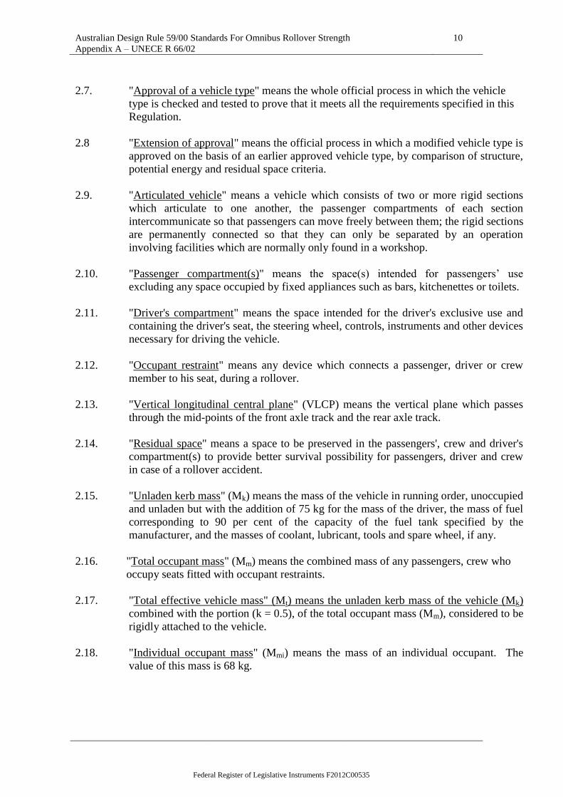
5.1.2. No part of the residual space shall project outside the contour of the deformed
structure.
The contour of the deformed structure shall be determined sequentially, between every
adjacent window and/or door pillar. Between two deformed pillars the contour shall
be a theoretical surface, determined by straight lines, connecting the inside contour
2/ 1 for Germany, 2 for France, 3 for Italy, 4 for the Netherlands, 5 for Sweden, 6 for Belgium, 7 for Hungary,
8 for the Czech Republic, 9 for Spain, 10 for Serbia, 11 for the United Kingdom, 12 for Austria, 13 for Luxembourg,
14 for Switzerland, 15 (vacant), 16 for Norway, 17 for Finland, 18 for Denmark, 19 for Romania, 20 for Poland,
21 for Portugal, 22 for the Russian Federation, 23 for Greece, 24 for Ireland, 25 for Croatia, 26 for Slovenia, 27 for
Slovakia, 28 for Belarus, 29 for Estonia, 30 (vacant), 31 for Bosnia and Herzegovina, 32 for Latvia, 33 (vacant), 34
for Bulgaria, 35 (vacant), 36 for Lithuania, 37 for Turkey, 38 (vacant), 39 for Azerbaijan, 40 for The former Yugoslav
Republic of Macedonia, 41 (vacant), 42 for the European Community (Approvals are granted by its Member States
using their respective ECE symbol), 43 for Japan, 44 (vacant), 45 for Australia, 46 for Ukraine, 47 for South Africa,
48 for New Zealand, 49 for Cyprus, 50 for Malta, 51 for the Republic of Korea, 52 for Malaysia, 53 for Thailand, 54
and 55 (vacant), 56 for Montenegro and 58 for Tunisia. Subsequent numbers shall be assigned to other countries in
the chronological order in which they ratify or accede to the Agreement Concerning the Adoption of Uniform
Technical Prescriptions for Wheeled Vehicles, Equipment and Parts which can be Fitted and/or be Used on Wheeled
Vehicles and the Conditions for Reciprocal Recognition of Approvals Granted on the Basis of these Prescriptions,
and the numbers thus assigned shall be communicated by the Secretary-General of the United Nations to the
Contracting Parties to the Agreement
Federal Register of Legislative Instruments F2012C00535
Australian Design Rule 59/00 Standards For Omnibus Rollover Strength
Appendix A – UNECE R 66/02
16
points of the pillars which were the same height above the floor level before the
rollover test (see Figure 1).
Figure 1 - Specification of the contour of the deformed structure
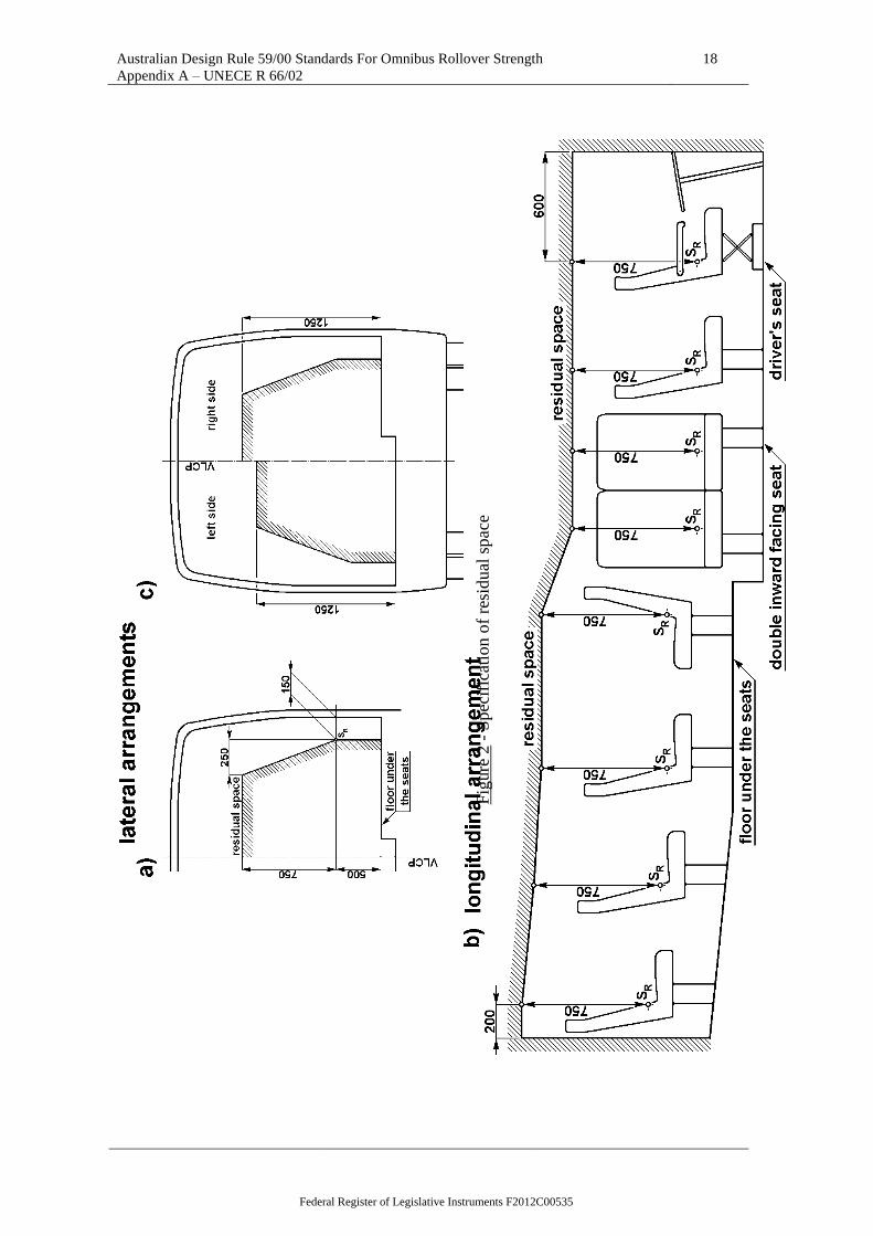
5.2. Residual space
The envelope of the vehicle's residual space is defined by creating a vertical
transverse plane within the vehicle which has the periphery described in Figures 2(a)
and 2(c), and moving this plane through the length of the vehicle (see Figure 2(b)) in
the following manner:
5.2.1. The SR point is located on the seat-back of each outer forward or rearward facing seat
(or assumed seat position), 500 mm above the floor under the seat, 150 mm from the
inside surface of the side wall. No account shall be taken of wheel arches and other
variations of the floor height. These dimensions shall also be applied in the case of
inward facing seats in their centre planes.
5.2.2. If the two sides of the vehicle are not symmetrical in respect of floor arrangement and,
therefore, the height of the SR points are different, the step between the two floor lines
of the residual space shall be taken as the longitudinal vertical centre plane of the
vehicle (see Figure 2(c));
5.2.3. The rearmost position of the residual space is a vertical plane 200 mm behind the SR
point of the rearmost outer seat, or the inner face of the rear wall of the vehicle if this
is less than 200 mm behind that SR point.
Federal Register of Legislative Instruments F2012C00535

Australian Design Rule 59/00 Standards For Omnibus Rollover Strength
Appendix A – UNECE R 66/02
17
The foremost position of the residual space is a vertical plane 600 mm in front of the
SR point of the foremost seat (whether passenger, crew, or driver) in the vehicle set at
its fully forward adjustment.
If the rearmost and foremost seats on the two sides of the vehicle are not in the same
transverse planes, the length of the residual space on each side will be different;
5.2.4. The residual space is continuous in the passenger, crew and driver compartment(s)
between its rearmost and foremost plane and is defined by moving the defined vertical
transverse plane through the length of the vehicle along straight lines through the SR
points on both sides of the vehicle. Behind the rearmost and in front of the foremost
seat's SR point the straight lines are horizontal.
5.2.5. The manufacturer may define a bigger residual space than is required for a given seat
arrangement, to simulate a worst case in a group of vehicle types to allow for future
design development.
Federal Register of Legislative Instruments F2012C00535
Australian Design Rule 59/00 Standards For Omnibus Rollover Strength
Appendix A – UNECE R 66/02
18
Fig
ure
2 -
Spec
ific
atio
n o
f re
sidual
spac
e
Federal Register of Legislative Instruments F2012C00535

Australian Design Rule 59/00 Standards For Omnibus Rollover Strength
Appendix A – UNECE R 66/02
19
5.3. Specification of rollover test on a complete vehicle as the basic approval method
The rollover test is a lateral tilting test (see Figure 3), specified as follows:
5.3.1. The complete vehicle is standing on the tilting platform, with blocked suspension and
is tilted slowly to its unstable equilibrium position. If the vehicle type is not fitted
with occupant restraints it will be tested at unladen kerb mass. If the vehicle type is
fitted with occupant restraints it will be tested at total effective vehicle mass;
5.3.2. The rollover test starts in this unstable vehicle position with zero angular velocity and
the axis of rotation runs through the wheel-ground contact points. At this moment the
vehicle is characterized by the reference energy ER (see paragraph 3.2.2.1. and Figure
3);
5.3.3. The vehicle tips over into a ditch, having a horizontal, dry and smooth concrete
ground surface with a nominal depth of 800 mm;
5.3.4. The detailed technical specification of the rollover test on a complete vehicle as the
basic approval test is given in Annex 5.
Figure 3 - Specification of the rollover test on a complete vehicle showing the path of
the centre of gravity through the starting, unstable equilibrium, position
Federal Register of Legislative Instruments F2012C00535
Australian Design Rule 59/00 Standards For Omnibus Rollover Strength
Appendix A – UNECE R 66/02
20
5.4. Specifications of equivalent approval tests
Instead of the rollover test on a complete vehicle, at the discretion of the
manufacturer, one of the following equivalent approval test methods can be chosen:
5.4.1. Rollover test on body sections which are representative of the complete vehicle, in
accordance with the specifications of Annex 6.
5.4.2. Quasi-static loading tests of body sections in accordance with the specifications of
Annex 7.
5.4.3. Quasi-static calculations based on the results of component tests in accordance with
the specifications of annex 8.
5.4.4. Computer simulation - via dynamic calculations - of the basic rollover test on a
complete vehicle in accordance with the specifications of Annex 9.
5.4.5. The basic principle is that the equivalent approval test method must be carried out in
such a way that it represents the basic rollover test specified in Annex 5. If the
equivalent approval test method chosen by the manufacturer cannot take account of
some special feature or construction of the vehicle (e.g. air-conditioning installation
on the roof, changing height of the waist rail, changing roof height) the complete
vehicle may be required by the technical service to undergo the rollover test specified
in Annex 5.
5.5. Testing of articulated vehicles
In the case of an articulated vehicle, each rigid section of the vehicle shall comply
with the general requirement specified in paragraph 5.1. Each rigid section of an
articulated vehicle may be tested separately or in combination as described in Annex
5, paragraph 2.3, or in Annex 3, paragraph 2.6.7.
5.6. Direction of rollover test
The rollover test shall be carried out on that side of the vehicle which is more
dangerous with respect to the residual space. The decision is made by the technical
service on the basis of the manufacturer's proposal, considering at least the following:
5.6.1. the lateral eccentricity of the centre of gravity and its effect on the reference energy in
the unstable, starting position of the vehicle, see paragraph 3.2.2.1;
5.6.2. the asymmetry of the residual space, see paragraph 5.2.2
5.6.3. the different, asymmetrical constructional features of the two sides of the vehicle, and
the support given by partitions or inner boxes (e.g. wardrobe, toilet, kitchenette). The
side with the lesser support shall be chosen as the direction of the rollover test.
Federal Register of Legislative Instruments F2012C00535

Australian Design Rule 59/00 Standards For Omnibus Rollover Strength
Appendix A – UNECE R 66/02
21
6. MODIFICATION AND EXTENSION OF APPROVAL OF A VEHICLE TYPE
6.1. Every modification of the approved vehicle type shall be advised to the
Administrative Department which granted the type approval. The Administrative
Department may then either,
6.1.1. agree that the modifications made are unlikely to have an appreciable effect and that
in any case the modified vehicle type still complies with the requirements of this
Regulation and constitutes part of a group of vehicle types together with the approved
vehicle type; or
6.1.2. require a further test report from the technical service responsible for conducting the
tests to prove that the new vehicle type complies with the requirements of this
Regulation and constitutes part of a group of vehicle types together with the approved
vehicle type; or
6.1.3. refuse the extension of approval and require a new approval procedure to be carried
out.
6.2. The decisions of the Administrative Department and the technical service shall be
based on the threefold criteria of the worst case:
6.2.1. the structural criterion means whether the superstructure is changed or not (see
Annex 4). If no change, or the new superstructure is stronger, this is favourable.
6.2.2. the energy criterion means whether the reference energy is changed or not. If the new
vehicle type has the same or smaller reference energy than the approved one, this is
favourable.
6.2.3. residual space criterion is based on the envelope surface of the residual space. If the
residual space of the new vehicle type is everywhere within the approved case residual
space, this is favourable.
6.3. If all three criteria described in paragraph 6.2. are changed favourably, the extension
of the approval shall be granted without further investigation.
If all of three answers are unfavourable, a new approval procedure is required.
If the answers are mixed, further investigations (tests, calculation, structural analysis,
for example) will be required. These investigations shall be determined by the
technical service cooperating with the manufacturer.
6.4. Confirmation or refusal of approval, specifying the alterations, shall be notified by the
procedure specified in paragraph 4.3. above to the Parties to the Agreement which
apply this Regulation.
Federal Register of Legislative Instruments F2012C00535
Australian Design Rule 59/00 Standards For Omnibus Rollover Strength
Appendix A – UNECE R 66/02
22
6.5. The Administrative Department issuing the extension of approval shall assign a series
number to each communication form drawn up for such an extension.
7. CONFORMITY OF PRODUCTION
7.1. The conformity of production procedure shall comply with those set out in the
Agreement, Appendix 2, (E/ECE/324-E/ECE/TRANS/505/Rev.2).
7.2. Every vehicle approved under this regulation shall be so manufactured as to conform
to the type approved by meeting the requirements set out in paragraph 5. above. Only
those elements which are nominated by the manufacturer as part of the superstructure
shall be checked.
7.3. The normal frequency of inspections authorised by the Administrative Department
shall be once every two years. If non-conformity is discovered in the course of one of
these visits, the Administrative Department may increase the visit frequency to re-
establish the conformity of production as rapidly as possible.
8. PENALTIES FOR NON-CONFORMITY OF PRODUCTION
8.1. The approval granted in respect of a vehicle type pursuant to this Regulation may be
withdrawn if the requirements laid down in paragraph 7. above are not complied with.
8.2. If a party to the Agreement applying this Regulation withdraws an approval it has
previously granted, it shall forthwith so notify the other Contracting Parties applying
this Regulation, by means of a copy of the approval form bearing at the end, in large
letters, the signed and dated annotation "APPROVAL WITHDRAWN".
9. PRODUCTION DEFINITELY DISCONTINUED
If the holder of the approval completely ceases to manufacture a type of vehicle
approved in accordance with this Regulation, he shall so inform the Administrative
Department which granted the approval. Upon receiving the relevant communication,
that Administrative Department shall inform the other Parties to the Agreement
applying this Regulation by means of a copy of the approval form bearing at the end,
in large letters, the signed and dated annotation "PRODUCTION DISCONTINUED".
Federal Register of Legislative Instruments F2012C00535

Australian Design Rule 59/00 Standards For Omnibus Rollover Strength
Appendix A – UNECE R 66/02
23
10. TRANSITIONAL PROVISIONS
10.1. As from the official date of entry into force of the 01 series of amendments, no
Contracting Party applying this Regulation shall refuse to grant ECE approval under
this Regulation as amended by the 01 series of amendments.
10.2. As from 60 months after the date of entry into force, Contracting Parties applying this
Regulation shall grant ECE approvals for new vehicle types as defined in this
Regulation only if the vehicle type to be approved meets the requirements of this
Regulation as amended by the 01 series of amendments.
10.3. Contracting Parties applying this Regulation shall not refuse to grant extensions of
approval to the preceding series of amendments to this Regulation.
10.4. ECE approvals granted under this Regulation, in its original form, earlier than
60 months after the date of entry into force and all extensions of such approvals, shall
remain valid indefinitely, subject to paragraph 10.6. below. When the vehicle type
approved to the preceding series of amendments meets the requirements of this
Regulation as amended by the 01 series of amendments, the Contracting Party which
granted the approval shall notify the other Contracting Parties applying this
Regulation thereof.
10.5. No Contracting Party applying this Regulation shall refuse national type approval of a
vehicle type approved to the 01 series of amendments to this Regulation.
10.6. Starting 144 months after the entry into force of the 01 series of amendments to this
Regulation, Contracting Parties applying this Regulation may refuse first national
registration (first entry into service) of a vehicle which does not meet the requirements
of the 01 series of amendments to this Regulation.
10.7. As from the date of entry into force of the 02 series of amendments, no Contracting
Parties applying this Regulation shall refuse to grant approval under this Regulation as
amended by the 02 series of amendments.
10.8. Until 48 months after the date of entry into force of the 02 series of amendments, no
Contracting Parties shall refuse national or regional approval of a vehicle approved to
the preceding series of amendments to this Regulation.
10.9. As from 9 November 2017, Contracting Parties may refuse first registration of a new
vehicle which does not meet the requirements of the 02 series of amendments to this
Regulation.
10.10. Notwithstanding paragraphs 10.8 and 10.9, approvals of vehicle categories and classes
granted to the preceding series of amendments to the Regulation, which are not
affected by the 02 series of amendments, shall remain valid and Contracting Parties
applying the Regulation shall continue to accept them.
Federal Register of Legislative Instruments F2012C00535

Australian Design Rule 59/00 Standards For Omnibus Rollover Strength
Appendix A – UNECE R 66/02
24
10.11. Contracting Parties applying this Regulation shall not refuse to grant extensions of
approval to the preceding series of amendments to this Regulation.
11. NAMES AND ADDRESSES OF TECHNICAL SERVICES RESPONSIBLE FOR
CONDUCTING APPROVAL TESTS AND OF ADMINISTRATIVE
DEPARTMENTS
The Parties to the Agreement which apply this Regulation shall communicate to the
United Nations secretariat the names and addresses of the technical services
responsible for conducting approval tests and of the Administrative Departments
which grant approval. Forms issued in other countries to certify approval or extension
or refusal or withdrawal of approval, are to be sent to the Administrative Departments
of all Parties to this Agreement.
Federal Register of Legislative Instruments F2012C00535

Australian Design Rule 59/00 Standards For Omnibus Rollover Strength
Appendix A – UNECE R 66/02
Annex 1
25
Annex 1
COMMUNICATION
(Maximum format: A4 (210 x 297 mm))
1/
concerning: 2/
APPROVAL GRANTED
APPROVAL EXTENDED
APPROVAL REFUSED
APPROVAL WITHDRAWN
PRODUCTION DEFINITELY DISCONTINUED
of a vehicle type with regard to the strength of its superstructure pursuant to Regulation No. 66.
Approval No.: .............................. Extension No.: .....................
1. Trade name or mark of the vehicle type: ...........................................................................
2. Vehicle type: .....................................................................................................................
3. Vehicle category/class3/
:......................................................................................................
4. Manufacturer's name and address: ....................................................................................
5. If applicable, name and address of the manufacturer's representative: .............................
6. Brief summary of description of the superstructure in respect of paragraph 3.2.2.2. of this
Regulation and Annex 4: ...................................................................................................
7. Reference number of detailed drawing showing the residual space used in the approval
procedure: ..........................................................................................................................
8. Unladen kerb mass (kg): ……………. and associated axle loads (kg): .........................
9. Maximum number of seats permitted to be fitted with occupant restraints .......................
10. The position of the centre of gravity of the unladen vehicle in the longitudinal, transverse
and vertical planes: ............................................................................................................
10.1. for unladen kerb mass: ........................................................................................................
10.2. for total effective mass: .........................................................................................................
11. If the vehicle is fitted with occupant restraints then additionally, the total effective
vehicle mass (kg): …………… and the associated axle loads (kg): ...............................
1/ Distinguishing number of the country which has granted/extended approval (see approval provisions in the
Regulation). 2/ Strike out what does not apply.
3/ As defined in Annex 7 to the Consolidated Resolution on the Construction of vehicles (R.E.3), (document
TRANS/WP.29/78/Rev.1/Amend.2 as last amended by Amend.4)
issued by : Name of the administration:
......................................
......................................
......................................
Federal Register of Legislative Instruments F2012C00535

Australian Design Rule 59/00 Standards For Omnibus Rollover Strength
Appendix A – UNECE R 66/02
Annex 1
26
12. The value of reference energy (ER) as specified in paragraph 3.2.2.1. of this Regulation:
.............................................................................................................................................
13. Vehicle submitted for approval on: ...................................................................................
14. Method of test or calculation employed for approval: ......................................................
15. Direction of the rollover test used or assumed during the approval procedure: ...............
.............................................................................................................................................
16. Technical service responsible for conducting approval tests: ...........................................
17. Date of test report issued by that service: .........................................................................
18. Number of report issued by that service: ..........................................................................
19. Approval granted/refused/extended/withdrawn: ...............................................................
20 Reason(s) for extension (if applicable): ............................................................................
21. Position of approval mark on the vehicle: .........................................................................
List of documents containing data specified, in paragraph 3.2. of the Regulation, and in the annex
referring to the approval test method which was used.
...........................................................................................................................................................
...........................................................................................................................................................
...........................................................................................................................................................
...........................................................................................................................................................
...........................................................................................................................................................
The listed documents are held by the Administrative Department and are available on request.
Place: ...............................................................................................................................................
Date: ................................................................................................................................................
Signature: .........................................................................................................................................
Federal Register of Legislative Instruments F2012C00535

Australian Design Rule 59/00 Standards For Omnibus Rollover Strength
Appendix A – UNECE R 66/02
Annex 2
27
Annex 2
ARRANGEMENT OF THE APPROVAL MARK
(See paragraph 4.4. of this Regulation)
The above approval mark affixed to a vehicle shows that the vehicle type concerned has, with
regard to the strength of the superstructure, been approved in the United Kingdom (E11) pursuant
to Regulation No. 66 under approval number 022431. The first two digits of the approval number
indicate that the approval was granted in accordance with the requirements of the 02 series of
amendments to Regulation No. 66.
022431
Federal Register of Legislative Instruments F2012C00535

Australian Design Rule 59/00 Standards For Omnibus Rollover Strength
Appendix A – UNECE R 66/02
Annex 3
28
Annex 3
DETERMINATION OF THE CENTRE OF GRAVITY OF THE VEHICLE
1. General principles
1.1. The reference and the total energy to be absorbed in the rollover test depend directly
on the position of the vehicle's centre of gravity position. Therefore, its determination
should be as accurate as practicable. The method of measurement of dimensions,
angles and load values, and the accuracy of measurement shall be recorded for
assessment by the technical service. The following accuracy of measuring apparatus
is required:
- for measurements less than 2000 mm, accuracy of 1 mm
- for measurements greater than 2000 mm, accuracy of 0.05 per cent
- for measured angles, accuracy of 1 per cent
- for measured load values accuracy of 0.2 per cent
The wheel-base(s) and the distance between the centres of the footprint of the
wheel(s) at each axle (the track of each axle) shall be determined from the
manufacturer's drawings.
1.2. Blocked suspension is specified as the condition for determining centre of gravity and
for carrying out the actual rollover test. The suspension shall be blocked in the normal
operating position as defined by the manufacturer
1.3. The position of the centre of gravity is defined by three parameters:
1.3.1. longitudinal distance (l1) from the centre line of front axle
1.3.2. transverse distance (t) from the vertical longitudinal central plane of the vehicle.
1.3.3. vertical height (h0) above the flat horizontal ground level when the tyres are inflated as
specified for the vehicle
1.4. A method for determining l1, t, h0, using load cells is described here. Alternative
methods using lifting equipment and/or tilt tables for example may be proposed by the
manufacturer to the technical service who will decide whether the method is
acceptable based on its degree of accuracy.
1.5. The centre of gravity position of the unladen vehicle (unladen kerb mass Mk) shall be
determined by measurements.
1.6. The centre of gravity position of the vehicle with total effective mass (Mt) may be
determined:
1.6.1. by measuring the vehicle in total effective mass condition, or
Federal Register of Legislative Instruments F2012C00535

Australian Design Rule 59/00 Standards For Omnibus Rollover Strength
Appendix A – UNECE R 66/02
Annex 3
29
1.6.2. by using the measured centre of gravity position in the unladen kerb mass condition
and considering the effect of the total occupant mass.
1.6.3. In the case of a double deck vehicle, the mass of the passengers both on the lower and
upper deck seats shall be taken into account.
2. Measurements
2.1. The position of the vehicle's centre of gravity shall be determined in the unladen kerb
mass condition or the total effective vehicle mass condition as defined in paragraphs
1.5. and 1.6. For the determination of the position of the centre of gravity in the total
effective vehicle mass condition, the individual occupant mass (factored by the
constant, k = 0.5) shall be positioned and rigidly held 100 mm above and 100 mm
forward of the R point (which is defined in Regulation No. 21, annex 5) of the seat.
2.2. The longitudinal (l1) and transverse (t) coordinates of centre of gravity shall be
determined on a common horizontal ground (see Figure A3.1) where each wheel or
twinned wheel of the vehicle is standing on an individual load cell. Each steered
wheel shall be set to its straight-ahead position.
2.3. The individual load-cell readings shall be noted simultaneously and shall be used to
calculate the total vehicle mass and centre of gravity position.
2.4. The longitudinal position of the centre of gravity relative to the centre of the contact
point of the front wheels (see Figure A3.1) is given by,
)(P
).LP(P).LP(Pl
total
2651431
where:
P1 = reaction load on the load cell under the left-hand wheel of the first axle
P2 = reaction load on the load cell under the right-hand wheel of the first axle
P3 = reaction load on the load cell under the left-hand wheel(s) of the second axle
P4 = reaction load on the load cell under the right-hand wheel(s) of the second axle
P5 = reaction load on the load cell under the left-hand wheel(s) of the third axle
P6 = reaction load on the load cell under the right-hand wheel(s) of the third axle
Ptotal = (P1+P2+P3+P4+P5+P6) = Mk unladen kerb mass; or,
= Mt total effective vehicle mass, as appropriate
L1 = the distance from centre of wheel on 1st axle to centre of wheel on second axle
L2 = the distance from centre of wheel on 1st axle to centre of wheel on third axle, if
fitted
Federal Register of Legislative Instruments F2012C00535

Australian Design Rule 59/00 Standards For Omnibus Rollover Strength
Appendix A – UNECE R 66/02
Annex 3
30
Figure A3.1 - Longitudinal position of the centre of gravity
2.5. The transverse position (t) of the vehicle's centre of gravity relative to its longitudinal
vertical centre plane (see figure A3.2) is given by,
total
365
243
121
P
1.
2
T)P(P
2
T)P(P
2
T)P(Pt
where:
T1 = distance between the centres of the footprint of the wheel(s) at each end of
the first axle
T2 = distance between the centres of the footprint of the wheel(s) at each end of
the second axle
T3 = distance between the centres of the footprint of the wheel(s) at each end of
the third axle
This equation assumes that a straight line can be drawn through the centre points of
T1, T2, T3. If this is not the case then a specialised formula will be required.
If the value of (t) is negative, then the centre of gravity of the vehicle is situated to the
right of the centreline of the vehicle.
Federal Register of Legislative Instruments F2012C00535

Australian Design Rule 59/00 Standards For Omnibus Rollover Strength
Appendix A – UNECE R 66/02
Annex 3
31
Figure A3.2 - Transverse position of centre of gravity
2.6. The height of the centre of gravity (h0) shall be determined by tilting the vehicle
longitudinally and using individual load-cells at the wheels of two axles.
2.6.1. Two load-cells shall be positioned on a common horizontal plane, to receive the front
wheels. The horizontal plane shall be at sufficient height above the surrounding
surfaces that the vehicle can be tilted forward to the required angle (see paragraph
2.6.2. below) without its nose touching that surface.
2.6.2. A second pair of load-cells shall be placed in a common horizontal plane on top of
support structures, ready to receive the wheels of the second axle of the vehicle. The
support structures shall be sufficiently tall to generate a significant angle of inclination
(> 20) for the vehicle. The greater the angle, the more accurate will be the
calculation – see figure A3.3. The vehicle is repositioned on the four load-cells, with
the front wheels chocked to prevent the vehicle rolling forward. Each steered wheel
shall be set to its straight-ahead steer position.
2.6.3. The individual load-cell readings shall be noted simultaneously and shall be used to
check the total vehicle mass and centre of gravity position.
2.6.4. The inclination of the tilting test shell be determined by the equation (see figure A3.3)
1L
Harcsin
where:
H = height difference between the footprints of the wheels of the first and second
axles
L1 = the distance from centre of wheel's first and second axles
2.6.5. The unladen kerb mass of the vehicle shall be checked as follows:
Ftotal = F1+F2+F3+F4 Ptotal Mk
Federal Register of Legislative Instruments F2012C00535

Australian Design Rule 59/00 Standards For Omnibus Rollover Strength
Appendix A – UNECE R 66/02
Annex 3
32
where:
F1 = reaction load on the load cell under the left hand wheel of the first axle
F2 = reaction load on the load cell under the right hand wheel of the first axle
F3 = reaction load on the load cell under the left hand wheel of the second axle
F4 = reaction load on the load cell under the right hand wheel of the second axle
If this equation is not fulfilled the measurement shall be repeated and/or the
manufacturer shall be asked to modify the value of the unladen kerb mass in the
technical description of the vehicle.
2.6.6. The height (ho) of the vehicle centre of gravity is given by:
total
4311o
P
FFLl
tg
1rh
where:
r = height of wheel centre (on first axle) above the load cell top surface
2.6.7. If the articulated vehicle is tested in separate sections, the centre of gravity position
shall be established separately for each section.
Figure A3.3 - Determination of height of centre of gravity
Federal Register of Legislative Instruments F2012C00535

Australian Design Rule 59/00 Standards For Omnibus Rollover Strength
Appendix A – UNECE R 66/02
Annex 4
33
Annex 4
VIEWPOINTS ON THE STRUCTURAL DESCRIPTION OF THE SUPERSTRUCTURE
1. General principles
1.1. The manufacturer shall define unambiguously the superstructure of the bodywork (see
figure A4.1, for example) and shall state:
1.1.1. which bays contribute to the strength and energy absorption of the superstructure;
1.1.2. which connecting elements between the bays contribute to the torsional stiffness of the
superstructure;
1.1.3. the mass distribution among the nominated bays;
1.1.4. which elements of the superstructure are assumed as rigid parts.
Figure A4. 1 - Derivation of the superstructure from the bodywork
Federal Register of Legislative Instruments F2012C00535

Australian Design Rule 59/00 Standards For Omnibus Rollover Strength
Appendix A – UNECE R 66/02
Annex 4
34
1.2. The manufacturer shall supply the following information about the elements of the
superstructure:
1.2.1. drawings, with all the significant geometrical measurements necessary to produce the
elements and to evaluate any change or alteration of the element;
1.2.2. the material of the elements referred to national, or international standards;
1.2.3. the joint technology between the structural elements (riveted, bolted, glued, welded,
type of welding, etc.).
1.3. Every superstructure shall have at least two bays: one in front of the centre of gravity
and one behind the centre of gravity.
1.4. No information is required about any elements of the bodywork, which are not parts
of the superstructure.
2. Bays
2.1. A bay is defined as a structural section of the superstructure forming a closed loop
between two planes which are perpendicular to the vertical longitudinal centre plane
(VLCP) of the vehicle. A bay contains one window (or door) pillar on each side of
the vehicle as well as side wall elements, a section of the roof structure and a section
of the floor and underfloor structure. Every bay has a transverse centre plane (CP)
perpendicular to the VLCP of the vehicle and passing through the centre points (Cp)
of the window-pillars (see figure A4.2)
2.2. The Cp is defined as a point at half window height and halfway across the pillar
width. If the Cp of the left-side and right- side pillars of a bay are not in the same
transverse plane, the CP of the bay is set halfway between the transverse planes of the
two Cp's.
2.3. The length of a bay is measured in the direction of the longitudinal axis of the vehicle,
and is determined by the distance between two planes perpendicular to the VLCP of
the vehicle. There are two limits which define the length of a bay: the window (door)
arrangement, and the shape and construction of the window (door) pillars.)
Federal Register of Legislative Instruments F2012C00535

Australian Design Rule 59/00 Standards For Omnibus Rollover Strength
Appendix A – UNECE R 66/02
Annex 4
35
Figure A4. 2 - Definition of length of bays
2.3.1. The maximum length of a bay is defined by the length of the two neighbouring
window (door) frames
ba2
1W
maxj
where:
a = the length of the window (door) frame behind the jth
pillar, and
i) b = the length of the window (door) frame in front of the jth
pillar
If the pillars on opposite sides of the bay are not in one transverse plane, or the
window frames on each side of the vehicle have different lengths (see figure A4.3),
the overall length, Wj of the bay is defined by:
2Lba2
1W minminmaxj
ii) where:
iii) amin = the smaller value of aright side or aleft side
iv) bmin = the smaller value of bright side or bleft side
L = the longitudinal offset between the centrelines of the pillars
on the left and right sides of the vehicle
Federal Register of Legislative Instruments F2012C00535

Australian Design Rule 59/00 Standards For Omnibus Rollover Strength
Appendix A – UNECE R 66/02
Annex 4
36
Figure A4. 3 - Definition of bay length when pillars on each side of the bay
are not in one transverse plane
2.3.2. The minimum length of a bay shall include the whole window pillar (including its
inclination, corner radii, etc.). If the inclination and corner radii exceed half the length
of the adjacent window then the next pillar shall be included in the bay.
2.4. The distance between two bays shall be defined as the distance between their CP's.
2.5. The distance of a bay from the centre of gravity of the vehicle shall be defined as the
perpendicular distance from its CP to the vehicle centre of gravity.
3. Connecting structures between the bays
3.1. The connecting structures between bays shall be clearly defined in the superstructure.
These structural elements fall into two distinct categories:
3.1.1. The connecting structures which form part of the superstructure. These elements shall
be identified by the manufacturer, in this design submission: they include:
3.1.1.1. side-wall structure, roof structure, floor structure, which connect several bays,
3.1.1.2. structural elements which reinforce one or more bays; for example, boxes under seats,
wheel arches, seat structures connecting side-wall to floor, kitchen, wardrobe and
toilet structures.
Federal Register of Legislative Instruments F2012C00535

Australian Design Rule 59/00 Standards For Omnibus Rollover Strength
Appendix A – UNECE R 66/02
Annex 4
37
3.1.2. The additional elements which do not contribute to the structural strength of the
vehicle but which may intrude into the residual space, for example: ventilation ducts,
hand luggage boxes, heating ducts.
4. Mass distribution
4.1. The manufacturer shall clearly define the portion of the mass of the vehicle attributed
to each of the bays of the superstructure. This mass distribution shall express the
energy absorbing capability and load bearing capacity of each bay. The following
requirements shall be met when defining the distribution of mass:
4.1.1. the sum of the masses attributed to each bay shall be related to the mass M of the
complete vehicle:
M)(mn
1j
j
where:
mj = the mass attributed to the jth
bay
n = the number of bays in the superstructure
M = Mk, unladen kerb mass; or,
= Mt, total effective vehicle mass, as appropriate
4.1.2. the centre of gravity of the distributed masses shall be in the same position as the
centre of gravity of the vehicle:
0)l(m j
n
1j
j
where:
lj = the distance of the jth
bay from the centre of gravity of the vehicle
(see paragraph 2.3.).
lj is positive, if the bay is in front of the centre of gravity and negative if it is
behind it.
4.2. The mass " mj" of each bay of the superstructure shall be defined by the manufacturer,
as follows:
4.2.1. the masses of the components of the "jth
" bay shall be related to its mass "mj" by:
j
s
1k
jk mm
where:
mjk = the mass of each component of the bay
s = the number of individual masses on the bay
Federal Register of Legislative Instruments F2012C00535

Australian Design Rule 59/00 Standards For Omnibus Rollover Strength
Appendix A – UNECE R 66/02
Annex 4
38
4.2.2. the centre of gravity of the component masses of a bay shall have the same transverse
position inside the bay as the bay's centre of gravity (see figureA4.4):
0zmym k
s
1k
jkk
s
1k
jk
where:
yk = the distance of the kth
mass component of the bay from the axis "Z" (see figure
A4.4).
yk will have a positive value on one side of the axis and a negative value on the
other side.
zk = the distance of the kth
mass component of the bay from the axis "Y",
zk will have a positive value on one side of the axis and a negative value on the
other side.
4.3. In the case where occupant restraints are part of the vehicle specification, the occupant
mass attributed to a bay shall be attached to that part of the superstructure which is
designed to absorb seat and occupant loadings.
Figure A4.4 - Distribution of mass in the cross section of a bay
Federal Register of Legislative Instruments F2012C00535

Australian Design Rule 59/00 Standards For Omnibus Rollover Strength
Appendix A – UNECE R 66/02
Annex 5
39
Annex 5
ROLLOVER TEST AS THE BASIC APPROVAL METHOD
1. The tilting bench
1.1. The tilting platform shall be sufficiently rigid and the rotation sufficiently controlled
to ensure simultaneous lifting of the axles of the vehicle with a difference of less than
1o in the platform's tilt angles measured below the axles.
1.2. The height difference between the horizontal lower plane of the ditch (see
figure.A5.1) and the plane of the tilting platform on which the bus is standing, shall be
800 20 mm.
1.3. The tilting platform, related to the ditch, shall be placed as follows (see figure A5.1):
1.3.1. the axis of its rotation is max 100 mm from the vertical wall of the ditch;
1.3.2. the axis of the rotation is max 100 mm below the plane of the horizontal tilting
platform.
Figure A5.1 - Geometry of the tilting bench
1.4. Wheel supports shall be applied at the wheels being close to the axis of rotation
against sliding of the vehicle sideways when tilting it. The main characteristics of the
wheel supports (see figure A5.1) shall be:
1.4.1. dimensions of the wheel support:
Height shall not be greater than two-thirds of the distance between the
surface on which the vehicle stands before it is tilted and part of the
rim of the wheel which is nearest to the surface
Width 20 mm
Edge radius 10 mm
Length 500 mm minimum;
max
max
max
Federal Register of Legislative Instruments F2012C00535
Australian Design Rule 59/00 Standards For Omnibus Rollover Strength
Appendix A – UNECE R 66/02
Annex 5
40
1.4.2. the wheel supports at the widest axle shall be placed on the tilting platform so that the
side of the tyre is at maximum 100 mm from the axis of rotation;
1.4.3. the wheel supports at the other axles shall be adjusted so that the vertical longitudinal
centre plane (VLCP) of the vehicle shall be parallel to the axis of rotation.
1.5. The tilting platform shall be constructed to prevent the vehicle moving along its
longitudinal axis.
1.6. The impact area of the ditch shall have a horizontal, uniform, dry and smooth concrete
surface.
2. Preparation of test vehicle
2.1. The vehicle to be tested need not be in a fully finished, "ready for operation"
condition. Generally, any alteration from the fully finished condition is acceptable if
the basic features and behaviour of the superstructure are not influenced by it. The
test vehicle shall be the same as its fully finished version in respect of the following:
2.1.1. the position of the centre of gravity, the total value of vehicle mass (unladen kerb
mass, or total effective vehicle mass where restraints are fitted) and the distribution
and location of masses, as declared by the manufacturer.
2.1.2. all of those elements which – according to the manufacturer - contribute to the
strength of the superstructure shall be installed in their original position (see Annex 4
to this Regulation).
2.1.3. elements, which do not contribute to the strength of the superstructure and are too
valuable to risk damage (e.g. drive chain, dashboard instrumentation, driver's seat,
kitchen equipment, toilet equipment, etc.) can be replaced by additional elements
equivalent in mass and method of installation. These additional elements must not
have a reinforcing effect on the strength of superstructure.
2.1.4. fuel, battery acid and other combustible, explosive or corrosive materials may be
substituted with other materials provided that the conditions of paragraph 2.1.1. are
met.
2.1.5. In the case where occupant restraint devices are part of the vehicle type, a mass shall
be attached to each seat fitted with an occupant restraint following one of these two
methods, at the choice of the manufacturer:
2.1.5.1. First method: That mass shall be:
2.1.5.1.1 50 per cent of the individual occupant mass (Mmi) of 68 kg,
2.1.5.1.2. placed to have its centre of gravity 100 mm above and 100 mm forward of the R
point of the seat as defined in Regulation No. 21, Annex 5.
2.1.5.1.3. fixed rigidly and securely so that it does not break away during the test.
Federal Register of Legislative Instruments F2012C00535

Australian Design Rule 59/00 Standards For Omnibus Rollover Strength
Appendix A – UNECE R 66/02
Annex 5
41
2.1.5.2 Second method: That mass shall be
2.1.5.2.1 an anthropomorphic ballast with a mass of 68 kg and shall be restrained with a 2 point
safety-belt. The ballast must allow guiding and positioning for safety-belts.
2.1.5.2.2. placed to have its centre of gravity and dimensioning according to figure A5.2.
2.1.5.2.3. fixed rigidly and securely so that it does not break away during the test.
chest breadth ≈ 315-322 mm
waist breadth ≈ 290-310 mm
hip breadth ≈ 325-342 mm
TOTAL MASS: 68 kg
(100)
(10
0)
200
630
620
230
220-240
15°
C.G.
R
250
90°
Figure A5.2.-Dimensions for the anthropomorphic ballast
2.2. The test vehicle shall be prepared as follows:
2.2.1. tyres shall be inflated to the pressure prescribed by the manufacturer.
2.2.2. the suspension system of the vehicle shall be blocked, i.e. the axles, the springs and
the suspension elements of the vehicle shall be fixed in relation to the bodywork.
The floor height above the horizontal tilting platform shall be according to the
manufacturer's
specification for the vehicle, dependent on whether it is loaded to unladen kerb
mass or total vehicle mass.
2.2.3. every door and opening window of the vehicle shall be closed but not locked.
2.3. The rigid sections of an articulated vehicle may be tested separately or in combination.
2.3.1. For testing the articulated sections as a combination, the sections of the vehicle shall
be fixed to each other in such a way that,
2.3.1.1. there is no relative movement between them during the roll-over process.
2.3.1.2. there is no significant change in mass distribution and centre of gravity positions.
Federal Register of Legislative Instruments F2012C00535

Australian Design Rule 59/00 Standards For Omnibus Rollover Strength
Appendix A – UNECE R 66/02
Annex 5
42
2.3.1.3. there is no significant change in the strength and deformation capability of the
superstructure.
2.3.2. For testing the articulated sections separately, the single-axle sections shall be
attached to an artificial support which keeps them in fixed relation to the tilting
platform during its movement from the horizontal to the point of roll-over. This
support shall meet the following requirements:
2.3.2.1. it shall be fixed to the structure in such a way that it does not cause either
reinforcement or extra additional load to the superstructure.
2.3.2.2. it shall be constructed so that it does not suffer any deformation which could change
the direction of the rollover of the vehicle.
2.3.2.3. its mass shall be equal to the mass of those elements, parts of the articulated joint,
which nominally belong to the section being tested, but which are not placed on it
(e.g. turntable and its floor, handholds, rubber sealing curtains, etc.).
2.3.2.4. its centre of gravity shall have the same height as the common centre of gravity of
those parts which are listed in paragraph 2.3.2.3.
2.3.2.5. it shall have an axis of rotation parallel to the longitudinal axis of the multi-axle
section of the vehicle, and passing through the points of contact of the tyres of that
section.
3. Test procedure, test process
3.1. The rollover test is a very rapid, dynamic process having distinguishable stages,
should be taken into consideration when a rollover test, its instrumentation and
measurement are planned.
3.2. The vehicle shall be tilted without rocking and without dynamic effects until it reaches
unstable equilibrium and commences its rollover. The angular velocity of the tilt
platform shall not exceed 5 degrees/sec. (0.087 radians/sec).
3.3. For inside observation high-speed photography, video, deformable templates,
electrical contact sensors or other suitable means shall be used to determine that the
requirements of paragraph 5.1. of this Regulation has been met. This shall be verified
at any places of the passenger, driver's and crew compartment where the residual
space seems to be endangered, the exact positions being at the discretion of the
technical service. At least two positions, nominally at the front and rear of the
passenger compartment(s) shall be used.
3.4. Outside observation and recording of the rollover and deformation process is
recommended, which means the following:
3.4.1. two high-speed cameras - one at the front and another at the rear . They should be
located far enough from the front and rear wall of the vehicle to produce a measurable
picture, avoiding wide-angle distortion in the shaded area, as shown in figure A5.3a.
Federal Register of Legislative Instruments F2012C00535

Australian Design Rule 59/00 Standards For Omnibus Rollover Strength
Appendix A – UNECE R 66/02
Annex 5
43
3.4.2. the position of the centre of gravity and the contour of the superstructure (see
figure A5.2b), is marked by stripes and bands to ensure correct measurements on the
pictures.
Figure A5.3a - Recommended field of view of outside camera
Figure A5.3b - Recommended marking of the centre of gravity position
and the contour of the vehicle
4. Documentation of the rollover test
4.1. Detailed description of the tested vehicle shall be given by the manufacturer in which:
Federal Register of Legislative Instruments F2012C00535

Australian Design Rule 59/00 Standards For Omnibus Rollover Strength
Appendix A – UNECE R 66/02
Annex 5
44
4.1.1. all the deviations between the fully finished vehicle type in running order and the
tested vehicle are listed.
4.1.2. the equivalent substitution (in respect of mass, mass distribution and installation) shall
be proved in every case, when structural parts, units are substituted by other units or
masses.
4.1.3. there is a clear statement of the position of centre of gravity in the tested vehicle
which may be based on measurements carried out on the test vehicle when it is ready
for test, or a combination of measurement (carried out on the fully finished vehicle
type) and calculation based on the mass substitutions.
4.2. The test report shall contain all the data (pictures, records, drawings, measured values,
etc.) which show:
4.2.1. that test was carried out according to this annex;
4.2.2. that the requirements given in paragraphs 5.1.1. and 5.1.2. of this Regulation are met
(or not);
4.2.3. the individual evaluation of inside observations;
4.2.4. all the data and information needed for the identification of the vehicle type, the test
vehicle, the test itself, and the personnel responsible for the test and its evaluation.
4.3. It is recommended to document in the test report the centre of gravity's highest and
lowest position related to the ground level of the ditch.
Federal Register of Legislative Instruments F2012C00535

Australian Design Rule 59/00 Standards For Omnibus Rollover Strength
Appendix A – UNECE R 66/02
Annex 6
45
Annex 6
ROLLOVER TEST USING BODY SECTIONS AS AN EQUIVALENT APPROVAL METHOD
1. Additional data and information
If the manufacturer chooses this method of testing, the following information shall be
given to the technical service in addition to the data, information and drawings listed
in paragraph 3. of this Regulation:
1.1. drawings of the body sections to be tested;
1.2. verification of the validity of the distribution of masses given in Annex 4, paragraph
4., upon successful completion of the body section rollover tests;
1.3 the measured masses of the body sections to be tested, and verification that their
centre of gravity positions are the same as that of the vehicle with unladen kerb mass
if not fitted with occupant restraints, or with total effective vehicle mass if occupant
restraints are fitted. (Presentation of measuring reports)
2. The tilting bench
The tilting bench shall meet the requirements given in Annex 5, paragraph 1.
3. Preparation of body sections
3.1. The number of the body sections to be tested shall be determined by the following
rules:
3.1.1. all the different bay configurations which are part of the superstructure shall be tested
in at least one body section;
3.1.2. every body section shall have at least two bays;
3.1.3. in an artificial body section (see paragraph 2.28. of this Regulation) the ratio of the
mass of any one bay to any other bay shall not exceed 2;
3.1.4. the residual space of the whole vehicle shall be well represented in the body sections,
including any peculiar combinations arising from the vehicles bodywork
configuration;
3.1.5. the whole roof structure shall be well represented in the body sections if there are
local specialities, like changing height, air condition installation, gas tanks, luggage
carrier, etc.
3.2. The bays of the body section shall be exactly the same structurally as they are
represented in the superstructure, as regards shape, geometry, material, joints.
Federal Register of Legislative Instruments F2012C00535

Australian Design Rule 59/00 Standards For Omnibus Rollover Strength
Appendix A – UNECE R 66/02
Annex 6
46
3.3. The connecting structures between the bays shall represent the manufacturer's
description of the superstructure (see Annex 4, paragraph 3.) and the following rules
shall be considered:
3.3.1. in the case of an original body section taken directly from the actual vehicle layout,
the basic and the additional connecting structures (see Annex 4 paragraph 3.1.) shall
be the same as that of the vehicle superstructure;
3.3.2. in the case of an artificial body section, the connecting structures shall be equivalent
in terms of strength, stiffness and behaviour to that of the vehicle superstructure;
3.3.3. those rigid elements which are not part of the superstructure but which can encroach
on the residual space during deformation, shall be installed into the body sections;
3.3.4. the mass of the connecting structures shall be included in the mass distribution, in
terms of attribution to a particular bay and distribution within that bay.
3.4. The body sections shall be equipped with artificial supports, to provide the same
centre of gravity positions and axis of rotation for them on the tilting platform as that
of the complete vehicle. The supports shall meet the following requirements:
3.4.1. they shall be fixed to the body section in such a way that they do not provide either
reinforcement or extra additional load on the body section;
3.4.2. they shall be sufficiently strong and rigid to resist any deformation which could
change the direction of the body section motion during the tilting and rollover process;
3.4.3. their mass shall be included in the mass distribution and centre of gravity position of
the body section.
3.5. The distribution of mass in the body section shall be arranged with the following
considerations:
3.5.1. The whole body section (bays, connecting structures, additional structural elements,
supports) shall be considered when checking the validity of the two equations given in
Annex 4, paragraph 4.2.1 and 4.2.2.;
3.5.2. any masses attached to the bays (see paragraph 4.2.2. and figure 4 of Annex 4) shall
be placed and fixed to the body section in such a way that they do not cause
reinforcement or additional load or limitation of the deformation.
3.5.3. In the case where occupant restraints are part of the vehicle type, the occupant masses
shall be considered as described in Annex 4 and Annex 5.
4. Test procedure
The test procedure shall be the same as described in paragraph 3. of Annex 5 for a
complete vehicle.
Federal Register of Legislative Instruments F2012C00535
Australian Design Rule 59/00 Standards For Omnibus Rollover Strength
Appendix A – UNECE R 66/02
Annex 6
47
5. Evaluation of the tests
5.1. The vehicle type shall be approved if all the body sections pass the rollover test and
the two equations in paragraph 4.1.1 and 4.1.2 of Annex 4 are fulfilled.
5.2. If one of the body sections fails the test, the vehicle type shall not be approved.
5.3. If a body section passes the rollover test, each of the bays which form that body
section are considered to have passed the rollover test, and the result can be quoted
used in future applications for approval, provided that the ratio of their masses
remains the same in the subsequent superstructure .
5.4. If a body section fails the rollover test, all the bays within that body section shall be
considered to have failed the test even if the residual space is invaded in only one of
the bays.
6. Documentation of body section rollover tests
The test report shall contain all the data necessary to demonstrate:
6.1. The construction of the tested body sections (dimensions, materials, masses, centre of
gravity position, construction methods).
6.2. that the tests were carried out according to this annex
6.3. whether, or not, the requirements - given in paragraph 5.1. of this Regulation - are met
6.4. the individual evaluation of the body sections and their bays.
6.5. the identity of the vehicle type, its superstructure, the tested body sections, the tests
themselves and the personnel responsible for the tests and their evaluation.
Federal Register of Legislative Instruments F2012C00535

Australian Design Rule 59/00 Standards For Omnibus Rollover Strength
Appendix A – UNECE R 66/02
Annex 7
48
Annex 7
QUASI- STATIC LOADING TEST OF BODY SECTIONS AS AN EQUIVALENT
APPROVAL METHOD
1. Additional data and information
This method of testing uses body sections as test units, each one built up from at least
two bays of the vehicle under appraisal, connected together with representative
structural elements. If the manufacturer chooses this method of testing, the following
additional information shall be supplied to the technical service, in addition to the data,
and drawings listed in paragraph 3.2. of this Regulation:
1.1. drawings of the body sections to be tested.
1.2. energy values to be absorbed by the individual bays of the superstructure, as well as
the energy values belonging to the body sections to be tested.
1.3. verification of the energy requirement, see paragraph 4.2. below, upon completion of
successful quasi-static loading tests of body sections.
2. Preparation of body sections
2.1. The manufacturer shall consider the requirements given in annex 6, paragraphs 3.1.,
3.2., and 3.3., when designing and producing the body sections for test.
2.2. The body sections shall be equipped with the residual space profile, at positions where
it is considered that the pillars or other structural elements are likely to intrude as a
result of the expected deformation.
3. Test procedure
3.1. Each body section to be tested shall be firmly and securely attached to the test bench
through a rigid underframe structure in such a way that,
3.1.1. local plastic deformation shall not occur around the attachment points;
3.1.2. the location and method of attachment shall not inhibit the formation and working of
expected plastic zones and hinges.
3.2. For application of the load to the body section, the following rules shall be considered:
3.2.1. the load shall be evenly distributed on the cantrail, through a rigid beam, which is
longer than the cantrail to simulate the ground in a rollover test, and which follows
the geometry of the cantrail.
Federal Register of Legislative Instruments F2012C00535
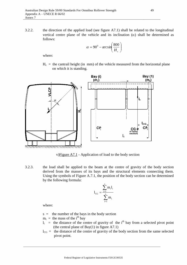
Australian Design Rule 59/00 Standards For Omnibus Rollover Strength
Appendix A – UNECE R 66/02
Annex 7
49
3.2.2. the direction of the applied load (see figure A7.1) shall be related to the longitudinal
vertical centre plane of the vehicle and its inclination () shall be determined as
follows:
cH
800arcsin900
where:
Hc = the cantrail height (in mm) of the vehicle measured from the horizontal plane
on which it is standing.
v)Figure A7.1 - Application of load to the body section
3.2.3. the load shall be applied to the beam at the centre of gravity of the body section
derived from the masses of its bays and the structural elements connecting them.
Using the symbols of Figure A.7.1, the position of the body section can be determined
by the following formula:
s
1i
i
s
1i
ii
CG
m
lm
l
where:
s = the number of the bays in the body section
mi = the mass of the ith
bay
li = the distance of the centre of gravity of the ith
bay from a selected pivot point
(the central plane of Bay(1) in figure A7.1)
lCG = the distance of the centre of gravity of the body section from the same selected
pivot point.
Federal Register of Legislative Instruments F2012C00535

Australian Design Rule 59/00 Standards For Omnibus Rollover Strength
Appendix A – UNECE R 66/02
Annex 7
50
3.2.4. the load shall be increased gradually, taking measurements of the associated
deformation at discrete intervals until the ultimate deformation (du ) when the residual
space is invaded by one of the elements of the body section.
3.3. When plotting the load-deflection curve:
3.3.1. the frequency of measurement shall be such as to produce a continuous curve (see
figure A.7.2).
3.3.2. the values of load and deformation shall be measured simultaneously.
3.3.3. the deformation of the loaded cantrail shall be measured in the plane and direction of
the applied load.
3.3.4. both load and deformation shall be measured to an accuracy of 1 per cent.
4. Evaluation of test results
4.1. From the plotted load-deformation curve the actual energy absorbed by the body
section (EBS) shall be expressed as the area below the curve (see figure
A.7.2).
Figure A7. 2 - Absorbed energy for the body section, derived from the measured
load-deformation curve
Federal Register of Legislative Instruments F2012C00535
Australian Design Rule 59/00 Standards For Omnibus Rollover Strength
Appendix A – UNECE R 66/02
Annex 7
51
4.2. The minimum energy required to be absorbed by the body section (Emin) shall be
determined as follows:
4.2.1. the total energy (ET) to be absorbed by the superstructure is:
ET = 0.75 M g h
where:
M = Mk, unladen kerb mass of the vehicle if there are no occupant restraints; or,
Mt, total effective vehicle mass when occupant restraints are fitted,
g = gravitational constant,
h = the vertical movement (in metres) of the vehicle centre of gravity during a
rollover
test, as determined in appendix 1 to this annex.
4.2.2. the total energy "ET" shall be distributed among the bays of the superstructure in the
proportions of their masses:
M
mEE i
Ti
where:
Ei = the absorbed energy by the "ith
" bay
mI = mass of the "ith
" bay, as determined in annex 4, paragraph 4.1
4.2.3. the minimum energy required to be absorbed by the body section (Emin) is the sum of
the energy of the bays comprising the body section:
S
1i
imin EE
4.3. The body section passes the loading test, if:
EBS Emin
In this case, all the bays which form that body section are considered to have passed
the quasi-static loading test and these results can be quoted in future requests for
approval provided that the component bays are not expected to carry a greater mass in
the subsequent superstructure.
4.4. The body section fails the loading test if:
EBS Emin
In this case all the bays which form that body section are considered to have failed the
test even if the residual space is invaded in only one of the bays.
Federal Register of Legislative Instruments F2012C00535

Australian Design Rule 59/00 Standards For Omnibus Rollover Strength
Appendix A – UNECE R 66/02
Annex 7
52
4.5. The vehicle type shall be approved if all the required body sections pass the loading
test.
5. Documentation of body section quasi-static loading tests
The test report shall follow the form and content of Annex 6, paragraph 6.
Federal Register of Legislative Instruments F2012C00535

Australian Design Rule 59/00 Standards For Omnibus Rollover Strength
Appendix A – UNECE R 66/02
Annex 7 Appendix 1
53
Annex 7 - Appendix 1
DETERMINATION OF THE VERTICAL MOVEMENT OF THE CENTRE OF GRAVITY
DURING ROLLOVER
The vertical movement (h) of centre of gravity related to the rollover test may be determined by
the graphical method shown below.
1. Using scaled drawings of the cross-section of the vehicle, the initial height (h1) of the
centre of gravity (position 1) above the lower plane of the ditch is determined for the
vehicle standing at its point of unstable equilibrium on the tilting platform (see
Figure A7.A1.1).
2. Using the assumption that the vehicle cross-section rotates around the edge of the
wheel supports, (point A in Figure A7.A1.1) the vehicle cross-section is drawn with
its cantrail just touching the lower plane of the ditch (see Figure A7.A1.2). In this
position the height (h2) of the centre of gravity (position 2) relative to the lower plane
of the ditch is determined.
Figure A7.A1.1 – Initial height of the vehicle centre of gravity
Federal Register of Legislative Instruments F2012C00535

Australian Design Rule 59/00 Standards For Omnibus Rollover Strength
Appendix A – UNECE R 66/02
Annex 7 Appendix 1
54
Figure A7.A1.2 - Determination of the vertical movement of the vehicle centre of gravity
3. The vertical movement of the centre of gravity (h) is,
h = h1 – h2
4. If more than one body sections are tested and each body section has a different
vertical movement (h), the vertical movement of centre of gravity (hi) shall be
determined for each body section and the combined mean value (h) is taken as,
k
1i
iΔhk
1Δh
where:
hi = the vertical movement of the centre of gravity of the ith
body section,
k = the number of body sections tested.
Federal Register of Legislative Instruments F2012C00535

Australian Design Rule 59/00 Standards For Omnibus Rollover Strength
Appendix A – UNECE R 66/02
Annex 8
55
Annex 8
QUASI-STATIC CALCULATION BASED ON TESTING OF COMPONENTS AS AN
EQUIVALENT APPROVAL METHOD
1. Additional data and information
If the manufacturer chooses this test method, the following information shall be given
to the technical service, in addition to the data and drawings listed in paragraph 3.2. of
this Regulation:
1.1. The location of plastic zones (PZ) and plastic hinges (PH) in the superstructure;
1.1.1. all the individual PZ's and PH's shall be uniquely identified on the drawing of the
superstructure in their geometrically defined locations (see figure A.8.1.)
1.1.2. structural elements between the PZ's and PH's can be treated as rigid or elastic parts in
the calculation, and their length shall be determined by their actual dimensions in the
vehicle.
1.2. The technical parameters of PZ's and PH's;
1.2.1. the cross-sectional geometry of the structural elements in which the PZ's and PH's are
located.
1.2.2. the type and direction of loading applied to each PZ and PH.
1.2.3. the load-deformation curve of each PZ and PH as described in appendix 1 of this
annex. The manufacturer may use either the static, or the dynamic characteristics of
the PZ's and PH's for the calculation but shall not mix static and dynamic
characteristics in one calculation.
Federal Register of Legislative Instruments F2012C00535
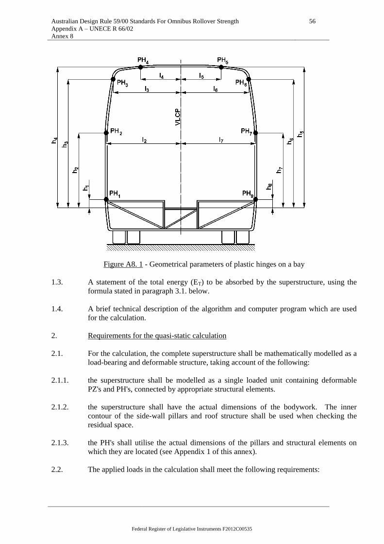
Australian Design Rule 59/00 Standards For Omnibus Rollover Strength
Appendix A – UNECE R 66/02
Annex 8
56
Figure A8. 1 - Geometrical parameters of plastic hinges on a bay
1.3. A statement of the total energy (ET) to be absorbed by the superstructure, using the
formula stated in paragraph 3.1. below.
1.4. A brief technical description of the algorithm and computer program which are used
for the calculation.
2. Requirements for the quasi-static calculation
2.1. For the calculation, the complete superstructure shall be mathematically modelled as a
load-bearing and deformable structure, taking account of the following:
2.1.1. the superstructure shall be modelled as a single loaded unit containing deformable
PZ's and PH's, connected by appropriate structural elements.
2.1.2. the superstructure shall have the actual dimensions of the bodywork. The inner
contour of the side-wall pillars and roof structure shall be used when checking the
residual space.
2.1.3. the PH's shall utilise the actual dimensions of the pillars and structural elements on
which they are located (see Appendix 1 of this annex).
2.2. The applied loads in the calculation shall meet the following requirements:
Federal Register of Legislative Instruments F2012C00535

Australian Design Rule 59/00 Standards For Omnibus Rollover Strength
Appendix A – UNECE R 66/02
Annex 8
57
2.2.1. the active load shall be applied in the transverse plane containing the centre of gravity
of the superstructure (vehicle) which is perpendicular to the vertical longitudinal centre
plane (VLCP) of the vehicle. The active load shall be applied on the cantrail of the
superstructure through an absolutely rigid load application plane, which extends in
both directions beyond the cantrail and any adjacent structure.
2.2.2. At the beginning of the simulation the load application plane shall touch the cantrail at
its most distant part from the vertical longitudinal central plane. The contact points
between the load application plane and the superstructure shall be defined to ensure an
exact load transfer.
2.2.3. the active load shall have an inclination related to the vertical longitudinal centre
plane of the vehicle (see figureA.8.2).
cH
800arcsin900
where:
Hc = the cantrail height (in mm) of the vehicle measured from the horizontal plane
on
which it is standing.
The direction of action of the active load shall not be changed during the calculation.
2.2.4. the active load shall be increased by small incremental steps and the whole structural
deformation shall be calculated at every loading step. The number of loading steps
shall exceed 100 and the steps shall be quasi-equal.
2.2.5. during the deformation process the load application plane may, in addition to parallel
translation, be allowed to rotate around the axis of intersection of the load application
plane with the transverse plane containing the centre of gravity, in order to follow the
asymmetric deformation of the superstructure.
2.2.6. the passive (supporting) forces shall be applied on the rigid underfloor structure
causing no influence on the structural deformation.
Federal Register of Legislative Instruments F2012C00535

Australian Design Rule 59/00 Standards For Omnibus Rollover Strength
Appendix A – UNECE R 66/02
Annex 8
58
Figure A8. 2 - Load application to the superstructure
2.3. The algorithm of the calculation and the computer program shall meet the following
requirements:
2.3.1. the program shall take account of non-linearities in the PH characteristics and large
scale structural deformations.
2.3.2. the program shall accommodate the working range of PH's and PZ's and shall stop the
calculation if the deformation of PH's exceeds the validated working range (see
Appendix 1 of this annex).
2.3.3. the program shall be able to calculate the total energy absorbed by the superstructure
at every incremental load step.
2.3.4. at every incremental load step, the program shall be able to demonstrate the deformed
shape of the bays forming the superstructure, and the position of every rigid part
which may intrude into the residual space. The program shall identify the incremental
load step at which the residual space is first invaded by any of the rigid structural
parts.
Federal Register of Legislative Instruments F2012C00535

Australian Design Rule 59/00 Standards For Omnibus Rollover Strength
Appendix A – UNECE R 66/02
Annex 8
59
2.3.5. the program shall be able to detect and identify the incremental load step at which
overall collapse of the superstructure begins; when the superstructure becomes
unstable and deformation continues without an increase of the load.
3. Evaluation of the calculation
3.1. The total energy (ET) to be absorbed by the superstructure shall be determined as
follows:
ET = 0.75 M..g .h
where:
M = Mk the unladen kerb mass of the vehicle, if there are no restraints, or
Mt the total effective vehicle mass when occupant restraints are fitted
G = the gravitational constant
h = the vertical movement (in metres) of the vehicle centre of gravity during a
rollover test, as determined in Appendix 1 of Annex 7
3.2. The absorbed energy (Ea) of the superstructure is calculated at the incremental load
step at which the residual space is first touched by any of the rigid structural parts.
3.3. The vehicle type shall be approved if Ea ET
4. Documentation of quasi-static calculation
The calculation report shall contain the following information:
4.1. detailed mechanical description of the superstructure containing the location of PZ's
and PH's and defining the rigid and elastic parts,
4.2. data obtained from the tests and the resultant graphs,
4.3. a statement of whether or not the requirement of paragraph 5.1. of this Regulation are
met,
4.4. identification of the vehicle type and the personnel responsible for the tests, the
calculations, and the evaluation.
Federal Register of Legislative Instruments F2012C00535

Australian Design Rule 59/00 Standards For Omnibus Rollover Strength
Appendix A – UNECE R 66/02
Annex 8 Appendix 1
60
Annex 8 - Appendix 1
CHARACTERISTICS OF PLASTIC HINGES
1. Characteristic curves
The general form of a Plastic Zone (PZ) characteristic curve is a non-linear load-
deformation relationship measured on structural parts of the vehicle in laboratory
tests.
Plastic Hinge characteristic curves are a bending moment (M) - rotational angle ()
relationship. The general form of a PH characteristic curve is shown in Figure A.8.
A.1.1
Figure A8. A1.1 - Characteristic curve for a plastic hinge
2. Aspects of deformation ranges
2.1. The "measured range" of the PH characteristic curve is the range of deformation over
which measurements have been made. The measured range may contain the fracture,
and/or the rapid hardening range. Only values of the PH characteristics which appear
in the measured range shall be used in the calculation.
2.2. The "working range" of the PH characteristic curve is the range covered by the
calculation.
The working range shall not exceed the measured range, and may contain the fracture,
but not the rapid-hardening range.
Federal Register of Legislative Instruments F2012C00535
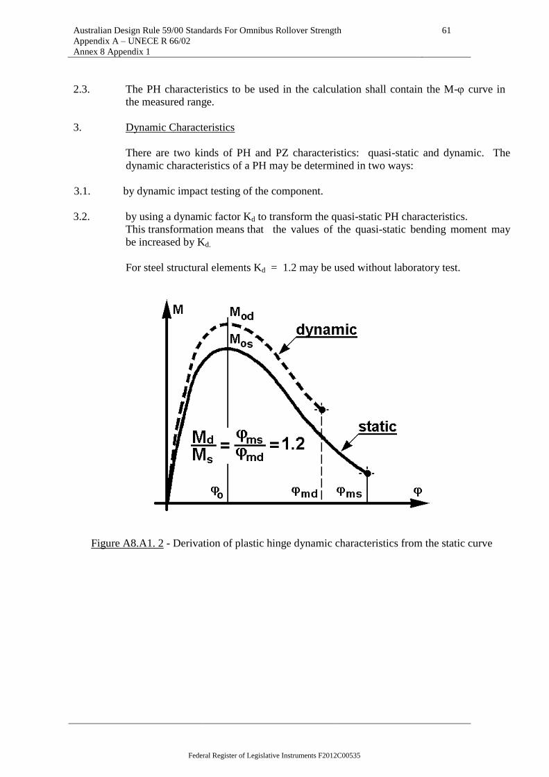
Australian Design Rule 59/00 Standards For Omnibus Rollover Strength
Appendix A – UNECE R 66/02
Annex 8 Appendix 1
61
2.3. The PH characteristics to be used in the calculation shall contain the M- curve in
the measured range.
3. Dynamic Characteristics
There are two kinds of PH and PZ characteristics: quasi-static and dynamic. The
dynamic characteristics of a PH may be determined in two ways:
3.1. by dynamic impact testing of the component.
3.2. by using a dynamic factor Kd to transform the quasi-static PH characteristics.
This transformation means that the values of the quasi-static bending moment may
be increased by Kd.
For steel structural elements Kd = 1.2 may be used without laboratory test.
Figure A8.A1. 2 - Derivation of plastic hinge dynamic characteristics from the static curve
Federal Register of Legislative Instruments F2012C00535

Australian Design Rule 59/00 Standards For Omnibus Rollover Strength
Appendix A – UNECE R 66/02
Annex 9
62
Annex 9
COMPUTER SIMULATION OF ROLLOVER TEST ON COMPLETE VEHICLE AS
AN EQUIVALENT APPROVAL METHOD
1. Additional data and information
The superstructure may be shown to meet the requirements specified in
paragraphs 5.1.1. and 5.1.2. of this Regulation by a computer simulation
method approved by the technical service.
If the manufacturer chooses this testing method, the following information
shall be supplied to the technical service in addition to the data, and
drawings listed in paragraph 3.2. of this Regulation;
1.1. A description of the applied simulation and calculation method which has
been utilised, and clear precise identification of the analysis software,
including at least, its producer, its commercial name, the version used and
contact details of the developer.
1.2. The material models and the input data utilized.
1.3. The values for defined masses, centre of gravity and the moments of inertia
used in the mathematical model.
2. The mathematical model
The model shall be capable of describing the real physical behaviour of the
rollover process, in accordance with Annex 5. The mathematical model
shall be constructed, and assumptions prescribed, in such a way that the
calculation gives conservative results. The model shall be built up with the
following considerations:
2.1. the technical service may require tests to be carried out on the actual vehicle
structure to prove the validity of the mathematical model and to verify the
assumptions made in the model.
2.2. the total mass and the centre of gravity position used in the mathematical
model shall be identical to those of the vehicle to be approved.
2.3. the mass distribution in the mathematical model shall correspond to the
vehicle to be approved. Moments of inertia used in the mathematical model
shall be calculated on the basis of this mass distribution.
3. Requirements for the algorithm and simulation program, and for computing
equipment
3.1. The position of the vehicle in unstable equilibrium at point of rollover,
and the position at first contact with the ground shall be specified. The
simulation program may start at the
Federal Register of Legislative Instruments F2012C00535

Australian Design Rule 59/00 Standards For Omnibus Rollover Strength
Appendix A – UNECE R 66/02
Annex 9
63
unstable equilibrium position, but shall start, at the latest, at the point of
first contact with the ground.
3.2. The initial conditions at the point of first contact with the ground shall be
defined using the change of potential energy from the unstable equilibrium
position.
3.3. The simulation program shall run, at least, until the maximum deformation
is reached.
3.4. The simulation program shall produce a stable solution, in which the result
is independent of the incremental time step.
3.5. The simulation program shall be able to calculate the energy components for
the energy balance at every incremental time step.
3.6. Non-physical energy components introduced by the process of mathematical
modelling (for example, "hourglass" and internal damping) shall not exceed
5 per cent of the total energy at any time.
3.7. The friction coefficient used at the ground contact shall be validated with
physical test results, or the calculation shall prove that the friction
coefficient chosen produces conservative results.
3.8. All the possible physical contacts between parts of the vehicle shall be taken
into account in the mathematical model.
4. Evaluation of the simulation
4.1. When the stated requirements for the simulation program are met, the
simulation of the changes in geometry of the interior structure and
comparison with the geometrical shape of the residual space can be
evaluated as defined in the paragraphs 5.1. and 5.2. of this Regulation.
4.2. If the residual space is not infringed during the rollover simulation, the
approval shall be granted.
4.3. If the residual space is infringed during the rollover simulation, the approval
shall be refused.
5. Documentation
5.1. The report on the simulation shall contain the following information:
5.1.1. all the data and information stated in paragraph 1. of this annex,
5.1.2. a drawing showing the mathematical model of the superstructure,
Federal Register of Legislative Instruments F2012C00535

Australian Design Rule 59/00 Standards For Omnibus Rollover Strength
Appendix A – UNECE R 66/02
Annex 9
64
5.1.3. a statement of the values of angle, velocity, and angular velocity at the
unstable equilibrium position of the vehicle and at the position of first
contact with the ground,
5.1.4. a table of the value of the total energy and the values of all its components
(kinetic energy, internal energy, hourglass energy), at time increments of 1
ms covering, at least, the period from first contact with the ground until the
maximum deformation is reached,
5.1.5. the assumed ground friction coefficient,
5.1.6. plots or data which show in an appropriate way that the requirements
specified in paragraphs 5.1.1. and 5.1.2. of this Regulation are met. This
requirement can be satisfied by the provision of a plot, against time, of the
distance between the inside contour of the deformed structure and the
periphery of the residual space,
5.1.7. a statement of whether, or not, the requirements specified in paragraphs
5.1.1. and 5.1.2. of this Regulation have been met,
5.1.8. all the data and information necessary for the clear identification of the
vehicle type, its superstructure, the mathematical model of the
superstructure, and the calculation itself.
5.2. It is recommended that the report also contains plots of the deformed
structure at the moment when maximum deformation occurs, giving an
overview of the superstructure and regions of large plastic deformation.
5.3. At the request of the technical service, further information shall be provided
and included in the report.
-----
Federal Register of Legislative Instruments F2012C00535

Australian Design Rule 59/00 Standards For Omnibus Rollover Strength
Appendix B – Australian Requirements
65
APPENDIX B
1. DEFINITIONS
1.1 "Passenger compartment" means the space intended for passengers' use excluding
any space occupied by fixed appliances such as bars, kitchenettes or toilets.
1.2 "Driver's compartment" means the space intended for the driver's exclusive use and
containing the driver's seat, the steering wheel, controls, instruments and other
devices necessary for driving the vehicle.
1.3 "Residual space" means a space to be preserved in the passengers', crew and
driver's compartment(s) to provide better survival possibility for passengers, driver
and crew in case of a rollover accident.
1.4 "Superstructure" means the load-bearing components of the bodywork as defined
by the manufacturer, containing those coherent parts and elements which contribute
to the strength and energy absorbing capability of the bodywork, and preserve the
residual space in the rollover test.
1.5 ―Body section‖ means a section containing at least two identical vertical pillars on
each side representative of a part or parts of the structure of the vehicle.
1.6 ―Total energy‖ means the energy assumed to be absorbed by the complete structure
of the vehicle. This may be determined as shown in clause 8.
2. GENERAL SPECIFICATIONS AND REQUIREMENTS
2.1 The superstructure of the vehicle shall be of sufficient strength to ensure that
during and after it has been subjected to one of the methods of test or calculation
prescribed in clause 3.:
2.2 No displaced part of the vehicle intrudes into the residual space, as specified in
clause 4., and
2.3 No part of the residual space projects outside the deformed structure.
2.4 The requirements of paragraph 2.1. above shall apply to the vehicle including all its
structural parts, members and panels and all projecting rigid parts such as luggage
racks, ventilation equipment, etc. However, bulkheads, partitions, rings or other
members reinforcing the superstructure of the vehicle and fixed appliances such as
bars, kitchenettes or toilets shall be ignored for the purposes of paragraph 2.1.
2.5 In the case of an articulated vehicle each part of the vehicle shall comply with the
requirements specified in paragraph 2.1. above.
3. TEST METHODS
3.1 Each type of vehicle shall be verified according to one of the following methods at
the discretion of the manufacturer or according to an alternative method approved
by the ‘Administrator ‘:
3.1.1 A roll-over test on a complete vehicle in accordance with the procedure set out in
clause 6.;
3.1.2 A roll-over test on a body section or sections representative of a complete vehicle
in accordance with clause 7.;
3.1.3 A pendulum test on a body section or sections in accordance with clause 8.; or
Federal Register of Legislative Instruments F2012C00535

Australian Design Rule 59/00 Standards For Omnibus Rollover Strength
Appendix B – Australian Requirements
66
3.1.4 A verification of strength of superstructure by calculation in accordance with
clause 9.
3.1.5 If the methods prescribed in paragraphs 3.1.2., 3.1.3. or 3.1.4. cannot take account
of a significant variation between one section of the vehicle and another, for
example an air-conditioning installation on the roof, additional test methods or
calculations shall be conducted.
3.2 In the absence of such additional information the vehicle may be required to
undergo the method of test prescribed in paragraph 3.1.1.
4. RESIDUAL SPACE
4.1 For the purpose of clause 2.1, the residual space means the volume within the
passenger compartment which is swept when the transverse vertical plane defined
in figure l(a) is moved in a straight line or lines so that the point "R" in figure l(a)
passes from the "R" point of the rearmost outer seat, through the "R" point of every
intermediate outer seat to the "R" point of the foremost outer passenger seat.
4.2 The position of the "R" point shown in figure l(b) shall be assumed to be 500 mm
above the floor under the passengers‘ feet, 300 mm from the inside surface of the
side of the vehicle and l00 mm in front of the seat back in the centre line of the
outboard seats.
5. INTERPRETATION OF TEST RESULTS
5.1 If body sections are tested, the test facility shall ensure that the vehicle complies
with the conditions specified in clause 8.4 which contains requirements for the
distribution of the main energy absorbing parts of the superstructure of a vehicle.
Federal Register of Legislative Instruments F2012C00535

Australian Design Rule 59/00 Standards For Omnibus Rollover Strength
Appendix B – Australian Requirements
67
Figure 1RESIDUAL SPACE
(all dimensions in millimetres)
The foremost passenger seat of the vehicle
750
750
750
750
750
750
300
100
A
Min
750
50
0
150
A
Cen
tre-l
ine
of
the
vehic
le
Cen
tre-
line
of
the s
eat
1 (a) LATERALLY
Templates to befixed on the floor
of the vehicle
1 (b) LONGITUDINALLY Section A-A of the vehicle in the verticle planeof the centre-line of the inboard seats.
R
RR R
R
Note: See requirements of clause 4.2. of the Regulation
R
Federal Register of Legislative Instruments F2012C00535

Australian Design Rule 59/00 Standards For Omnibus Rollover Strength
Appendix B – Australian Requirements
68
6. ROLL-OVER TEST ON A COMPLETE VEHICLE
6.1 TEST CONDITIONS
6.1.1 While the vehicle need not be in a fully finished condition it shall be representative
of production vehicles in respect of unladen mass, centre of gravity and distribution
of mass as declared by the manufacturer.
6.1.2 Driver and passenger seats shall be placed with their backs, if adjustable, in their
most upright position. The height of the seats, if adjustable, shall be the highest
position.
6.1.3 Every door and opening window of the vehicle shall be closed and latched but not
locked. Windows and glazed bulkheads or screens may be glazed or unglazed at
the applicant‘s discretion. If they are unglazed an equivalent weight shall be
imposed on the vehicle at the appropriate positions.
6.1.4 Tyres shall be inflated to the pressure prescribed by the vehicle manufacturer and,
if the vehicle has an air-spring suspension system, the air supply to the air springs
shall be ensured. Any automatic levelling system shall be adjusted with the vehicle
on a flat, horizontal surface to the level specified by the manufacturer. Shock
absorbers shall operate normally.
6.1.5 Fuel, battery acid and other combustible, explosive or corrosive materials may be
substituted by other materials provided that the conditions prescribed in clause
6.1.1 above are met.
6.1.6 The impact area shall consist of concrete or other rigid material.
6.2 TEST PROCEDURES (see figure 2)
6.2.1 The vehicle shall be placed on a platform in order to be rolled over on one side.
This side shall be specified by the manufacturer.
6.2.2 The position of the vehicle on the platform shall be such that when the platform is
horizontal:
6.2.2.1 the axis of rotation is parallel to the longitudinal axis of the vehicle,
6.2.2.2 the axis of rotation is 0-200 mm from the vertical step between the two levels,
6.2.2.3 the axis of rotation is 0-l00 mm from the side of the tyre at the widest axle,
6.2.2.4 the axis of rotation is 0-l00 mm below the horizontal starting plane on which the
tyres stand, and
6.2.2.5 the difference between the height of the horizontal starting plane and the horizontal
lower plane on which impact takes place shall be not less than 800 mm.
6.2.3 Means shall be provided to prevent the vehicle moving along its longitudinal axis.
6.2.4 The test apparatus shall prevent the tyres from sliding sideways in the direction of
roll-over by means of side walls.
6.2.5 The test apparatus shall ensure the simultaneous lifting of the axles of the vehicle.
6.2.6 The vehicle shall be tilted without rocking and without dynamic effects until it rolls
over. The angular velocity shall not exceed 5 degrees per second (0.087 rad/sec).
Federal Register of Legislative Instruments F2012C00535

Australian Design Rule 59/00 Standards For Omnibus Rollover Strength
Appendix B – Australian Requirements
69
6.2.7 High-speed photography, deformable templates or other suitable means shall be
used to determine that the requirement of clause 2.1 has been met. This shall be
verified by the test facility at not less than two positions, nominally at the front and
rear of the passenger compartment, the exact positions being chosen to ensure that
compliance is demonstrated in the worts position(s).
Templates shall be fixed to substantially non-deformable parts of the structure, e.g.
the floor of the vehicle.
Figure 2
Federal Register of Legislative Instruments F2012C00535

Australian Design Rule 59/00 Standards For Omnibus Rollover Strength
Appendix B – Australian Requirements
70
7. ROLL-OVER TEST ON A BODY SECTION
7.1 TEST CONDITIONS
7.1.1 The body section shall represent a section of the unladen vehicle.
7.1.2 The geometry of the body section, the axis of rotation and the position of the centre
of gravity in the same vertical and lateral directions shall be representative of the
complete vehicle.
7.1.3 The mass of the body section, expressed as a percentage of the unladen mass of the
vehicle, shall be specified by the manufacturer.
7.1.4 The energy to be absorbed by the body section, expressed as a percentage of the
total energy which would be absorbed by a complete vehicle, shall be specified by
the manufacturer.
7.1.5 The percentage of total energy described in clause 7.1.4 shall not be less than the
percentage of total mass described in clause 7.1.3.
7.1.6 The test conditions specified in clause 6.1.6 and in clauses 8.2.1 to 8.2.6 shall
apply.
7.2 TEST PROCEDURE
7.2.1 The test procedures shall be the same as the procedure described in clause 6.,
except that the body section described above shall be used instead of a complete
vehicle.
8. PENDULUM TEST ON A BODY SECTION
8.1 ENERGY LEVEL AND DIRECTION OF IMPACT
8.1.1 The energy to be transmitted to a particular body section shall be the sum of the
energies declared by the manufacturer to be allocated to each of the cross-sectional
rings included in that particular body section.
8.1.2 The appropriate proportion of the energy prescribed in figure 3 and clause 8.1.3
shall be applied to the body section by the pendulum such that at the moment of
impact the direction of motion of the pendulum makes an angle of 25o (+0
o; -5
o)
to the central longitudinal vertical plane of the body section. The precise angle
within this range may be specified by the vehicle manufacturer.
Federal Register of Legislative Instruments F2012C00535

Australian Design Rule 59/00 Standards For Omnibus Rollover Strength
Appendix B – Australian Requirements
71
Figure 3
8.1.3 CALCULATION OF TOTAL ENERGY (E*)
If the fall of the centre of gravity (h) is determined by graphical method (figure 3) E* may be taken to be given by the formula:
E* = 0.75 M.g.h. (Nm) Alternatively, E* may be calculated by the formula:
where: M = the unladen mass of the vehicle (kg) g = 9.8 m/s
2
W = the overall width of the vehicle (m) Hs = the height of the centre of gravity of the unladen vehicle (m) H = the height of the vehicle (m)
(Nm)H
H8.08.0H
2H
WH
2
W M.g. 0.75 = *E s222
s
2
Federal Register of Legislative Instruments F2012C00535

Australian Design Rule 59/00 Standards For Omnibus Rollover Strength
Appendix B – Australian Requirements
72
8.2 TEST CONDITIONS
8.2.1 A sufficient number of tests shall be carried out for the test facility conducting the
test to be satisfied that the requirement specified in clause 2.1 has been met.
8.2.2 For the purposes of the test body sections shall have sections of the normal
structure fitted between the pillars in relation to the floor, underframe, sides and
roof. Sections of such items as luggage racks, ventilation ducting, etc. where fitted,
shall also be included.
8.2.3 Every door and opening window of the body section shall be closed and latched but
not locked. Windows and glazed bulkheads or screens may be glazed or unglazed
at the applicant‘s discretion.
8.2.4 Where appropriate seats may also be included, at the option of the manufacturer, in
their normal position in relation to the structure of the body section. The normal
fixings and joints between all members and attachments shall be incorporated. The
backrests if adjustable shall be in their most upright position and the height of the
seats if adjustable shall be the highest position.
8.2.5 The side of the body section to be impacted shall be at the discretion of the
manufacturer. Where more than one body section is required to be tested both shall
be impacted on the same side.
8.2.6 High speed photography, deformable templates or other suitable means shall be
used to determine that the requirement specified in clause 2.1 has been met.
Templates shall be fixed to a substantially non-deformable part of the structure.
8.2.7 The body section to be tested shall be firmly and securely attached to the mounting
frame through the cross-bearers or parts which replace these in such a way that no
significant energy is absorbed in the support frame and its attachments during the
impact.
8.2.8 The pendulum shall be released from such a height that it strikes the body section
at a speed of between 3 and 8 m/s.
8.3 DESCRIPTION OF THE PENDULUM
8.3.1 The striking face of the pendulum shall be made of steel, or plywood 20 mm ± 5
mm thick, and the mass of the pendulum shall be evenly distributed. Its striking
face shall be rectangular and flat, having a width of not less than the width of the
body section being tested and a height of not less than 800 mm. Its edges shall be
rounded to a radius of curvature of not less than l5 mm.
8.3.2 The body of the pendulum shall be rigidly attached to two rigid bars. The axis of
the bars shall be not less than 3,500 mm from the geometric centre of the body of
the pendulum.
8.4 REQUIREMENTS FOR THE DISTRIBUTION OF THE MAIN ENERGY ABSORBING PARTS OF THE SUPERSTRUCTURE
8.4.1 A sufficient number of tests shall be carried out for the test facility to be satisfied
that the complete vehicle meets the requirements of clause 2.1. This shall not
necessarily require more than one test.
Federal Register of Legislative Instruments F2012C00535

Australian Design Rule 59/00 Standards For Omnibus Rollover Strength
Appendix B – Australian Requirements
73
8.4.2 Calculations based on data obtained from a test on a body section may be used to
demonstrate the acceptability of another body section which is not identical with
the body section already tested if it has many structural features in common with it.
8.4.3 The manufacturer shall declare which pillars of the superstructure are considered as
contributing to its strength and shall also declare the amount of energy (Ei) that
each pillar is intended to absorb. These declarations shall meet the following
criteria:
(1) E E *i
i = 1
i = m
Where m is the total number of declared pillars
(2) (a) E E *iF
i = 1
i = n
0.4Where n is the number of declared pillars forward of the
centre of gravity of the vehicle
(b) E E *iR
i = 1
i = p
0.4Where p is the number of declared pillars to the rear of the
centre of gravity of the vehicle
(3) LF > 0.4 1f
(4) LR > 0.4 1r
(5)
d
d
max
min
2 5.
This shall apply only where dmax is greater than 0.8 5
maximum deflection permitted without intrusion of the
residual space.
Where:
Ei is the declared amount of energy that can be absorbed by ith
pillar of the superstructure.
EiF is the declared amount of energy that can be absorbed by ith
pillar forward of the centre of gravity of the vehicle.
EiR is the declared amount of energy that can be absorbed by the ith
pillar to the rear of the centre of gravity of the vehicle.
E* is the total energy to be absorbed by the complete structure of the vehicle.
dmax is the greatest amount of deflection measured in the direction of impact of any section of the body structure after it has absorbed its own declared impact energy.
dmin is the least amount of deflection, measured in the direction of impact and at the same point on the bay as dmax, of any section of the body structure after it has absorbed its own declared impact energy.
Federal Register of Legislative Instruments F2012C00535

Australian Design Rule 59/00 Standards For Omnibus Rollover Strength
Appendix B – Australian Requirements
74
Where:
1if is the distance from the centre of gravity of the vehicle of the ith
pillar forward of the centre of gravity.
1ir is the distance from the centre of gravity of the vehicle of the ith
pillar rearward of the centre of gravity.
lf is the distance of the front of the vehicle from the centre of gravity of the vehicle.
1r is the distance of the rear of the vehicle from the centre of gravity of the vehicle.
vehicle theofgravity
of centre theofrear the topillars
declared theof distance mean Weighted
E
l E
= L
iL
p = i
l = i
iLiL
p = i
l = i L
L =
E l
E
Weighted mean distance of the declared
pillars to the rear of the centre of
gravity of the vehicle
Ri = l
i = p
iR iR
i = l
i = p
iR
Cg
1r1f
L
lif lir
Federal Register of Legislative Instruments F2012C00535

Australian Design Rule 59/00 Standards For Omnibus Rollover Strength
Appendix B – Australian Requirements
75
9. VERIFICATION OF STRENGTH OF SUPERSTRUCTURE BY
CALCULATION
9.1.1 A superstructure or sections may be shown to meet the requirement specified in
clause 2.1 by a calculation method.
9.1.2 If the structure is likely to be subject to deformations beyond the elastic limit of the
materials used then the calculations shall simulate the behaviour of the structure
when undergoing large plastic deformations.
9.1.3 The test facility responsible for conducting the tests may be required to carry out
test on joints or parts of the structure to verify the assumptions made in the
calculation.
9.2 PREPARATIONS FOR CALCULATION
9.2.1 Calculations cannot be started until the structure has been analysed and a
mathematical model of it produced. This will define the separate members to be
considered and identify the points at which plastic hinges may develop. The
dimension of the members and the properties of materials used must be stated.
Physical tests must be made on the hinge points to determine the force (moment of
rotation) - deformation characteristics in the plastic mode as this is essential data
for the calculations. The strain rate and the dynamic yield stress appropriate for this
strain rate must be determined. If the calculation method will not indicate when a
significant fracture will occur it will be essential to determine, by experiment
separate analysis or appropriate dynamic tests that significant fractures will not
occur. The assumed distribution of loading along the length of a vehicle shall be
stated.
9.2.2 The calculation method shall include the deformations up to the elastic limits of the
materials followed by the identification of where plastic hinges will form and the
subsequent formation of other plastic hinges unless the position and sequence of
formation of plastic hinges is known from previous experience. The method shall
accommodate the changes of geometry of the structure that take place, at least up to
the stage where the deformations have passed the acceptable limits.
Unless otherwise approved for the purposes of demonstration of compliance to this
rule it is acceptable for the computer programme to exceed the measured force
(moment of rotation) as determined by physical test by 10%.
9.2.3 The calculations shall simulate the energy and the direction of impact which would
occur if that particular superstructure were to be submitted to the roll-over tests
prescribed in clause 6. The validity of the calculation method shall have been
established by comparison with the results of physical tests, which need not
necessarily have been made in connection with the vehicle now being approved.
9.3 When a calculation method is used for a section of a complete structure, the same
conditions shall apply as stated above for the complete vehicle.
Federal Register of Legislative Instruments F2012C00535

Australian Design Rule 59/00 Standards For Omnibus Rollover Strength
Compilation Notes
76
COMPILATION NOTES
This compilation of Vehicle Standard (Australian Design Rule 59/00 – Standards For Omnibus
Rollover Strength) 2007 includes all the instruments set out in the Table of Instruments. The
Table of Amendments provides a history of clauses that have been amended, inserted or deleted.
Table of Instruments
Name of Instrument Registration
Date
Commencement
Date
Vehicle Standard (Australian Design Rule 59/00 –
Standards For Omnibus Rollover Strength) 2007
(see F2007L04077)
12/10/2007 13/10/2007
Vehicle Standard (Australian Design Rule 59/00 –
Standards For Omnibus Rollover Strength) 2007
Amendment 1 (see F2012L01576)
18 /07/2012 19/07/2012
Table of Amendments
Clause affected How affected Amending instrument
4.2 am Amendment 1
4.2.1 to 4.2.2 del Amendment 1
4.3 am Amendment 1
4.4 am Amendment 1
6.1 am Amendment 1
7 am Amendment 1
8.2 del Amendment 1
Appendix A
Title Page
am Amendment 1
Appendix A
1
am Amendment 1
Appendix A
Ref and footnote to 1
ad Amendment 1
Appendix A
2.4
am Amendment 1
Appendix A
2.5
ad
Amendment 1
Appendix A
2.5 to 2.32
2.6 to 2.33
Amendment 1
Appendix A
2.10, 2.23, 2.32, 2.33, 3.2.2.1, 4.2,
5.5, 6.1.1
am
Amendment 1
Appendix A
Ref and footnote to 4.4.1
1 2
am
Amendment 1
Appendix A
10.7 to 10.11
ad Amendment 1
Appendix A, Annex 1, 3
am Amendment 1
Federal Register of Legislative Instruments F2012C00535

Australian Design Rule 59/00 Standards For Omnibus Rollover Strength
Compilation Notes
77
Table of Amendments (continued)
Clause affected How affected Amending instrument
footnote to 3 ad Amendment 1
Appendix A, Annex 2 am Amendment 1
Appendix A, Annex 3, 1.6.3 ad Amendment 1
Appendix A, Annex 5, 3.3 am Amendment 1
Appendix A, Annex 6, 3.1.3, 3.5.1,
5.1
am Amendment 1
Appendix A, Annex 7, Appendix
1, title of figure A7.A1.1, 4
am Amendment 1
Appendix A, Annex 7, 4 am Amendment 1
ad = added or inserted
am = amended
del = deleted or removed
rr = removed and replaced
= clause renumbered. This takes the format of old no. new no.
Federal Register of Legislative Instruments F2012C00535