Embed Size (px)
Citation preview
VEHICLE MASS REDUCTION WITH THE HELP OF 3G+ OPTIMIZATION TECHNIQUE – A FINITE ELEMENT STUDY
Rahul Makwana, Pratik Deshpande and Chetan Madivalar,
Detroit Engineered Products Inc.

• INTRODUCTION
• OBJECTIVE
• METHODOLOGY
• RESULTS
• DISCUSSION
• CONCLUSION
TABLE OF CONTENTS
Paper # (if applicable) 2
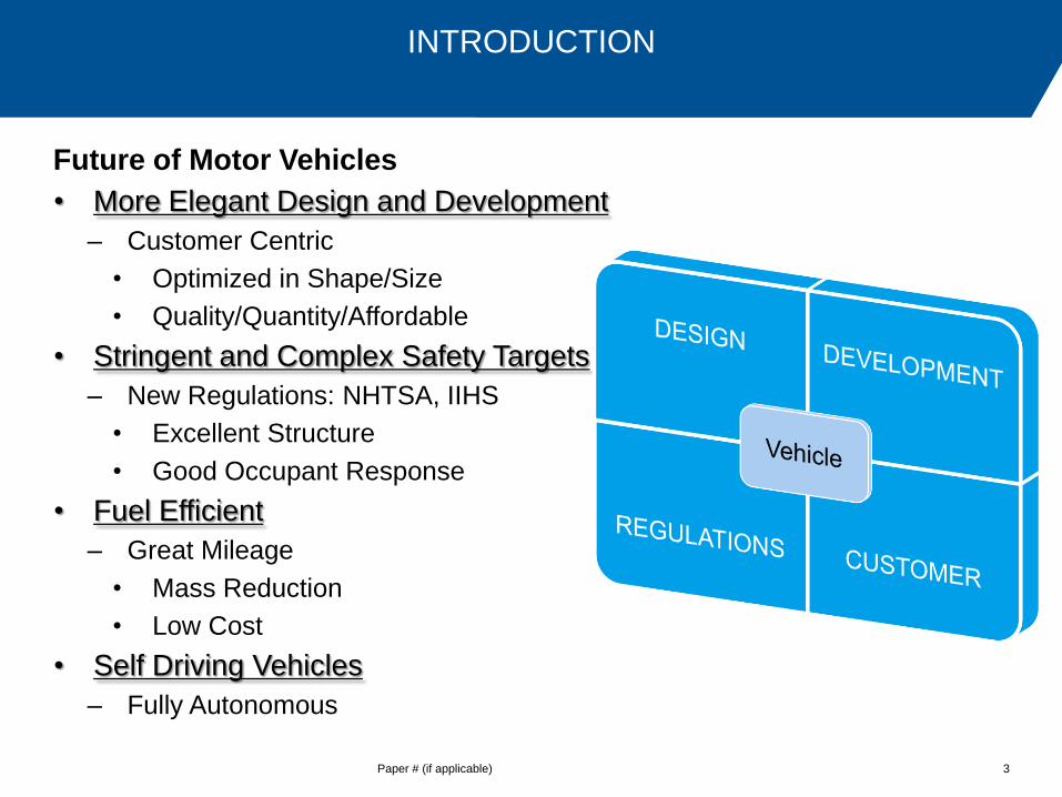
Future of Motor Vehicles
• More Elegant Design and Development
– Customer Centric
• Optimized in Shape/Size
• Quality/Quantity/Affordable
• Stringent and Complex Safety Targets
– New Regulations: NHTSA, IIHS
• Excellent Structure
• Good Occupant Response
• Fuel Efficient
– Great Mileage
• Mass Reduction
• Low Cost
• Self Driving Vehicles
– Fully Autonomous
INTRODUCTION
Paper # (if applicable) 3
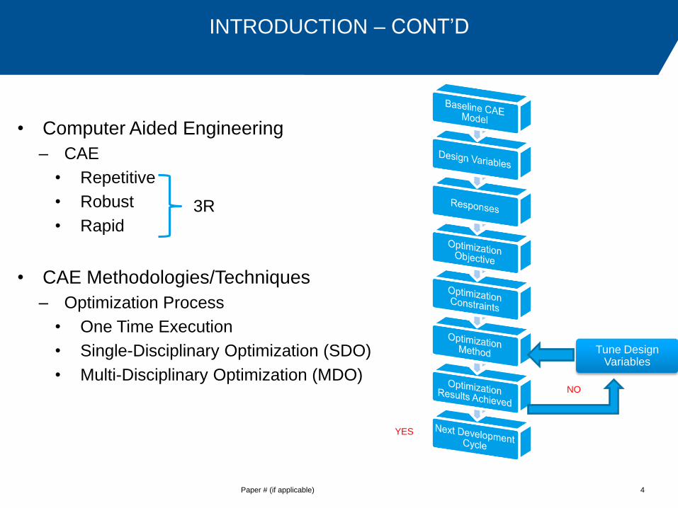
• Computer Aided Engineering
– CAE
• Repetitive
• Robust
• Rapid
• CAE Methodologies/Techniques
– Optimization Process
• One Time Execution
• Single-Disciplinary Optimization (SDO)
• Multi-Disciplinary Optimization (MDO)
INTRODUCTION – CONT’D
Paper # (if applicable) 4
3R
YES
NO
Tune Design Variables
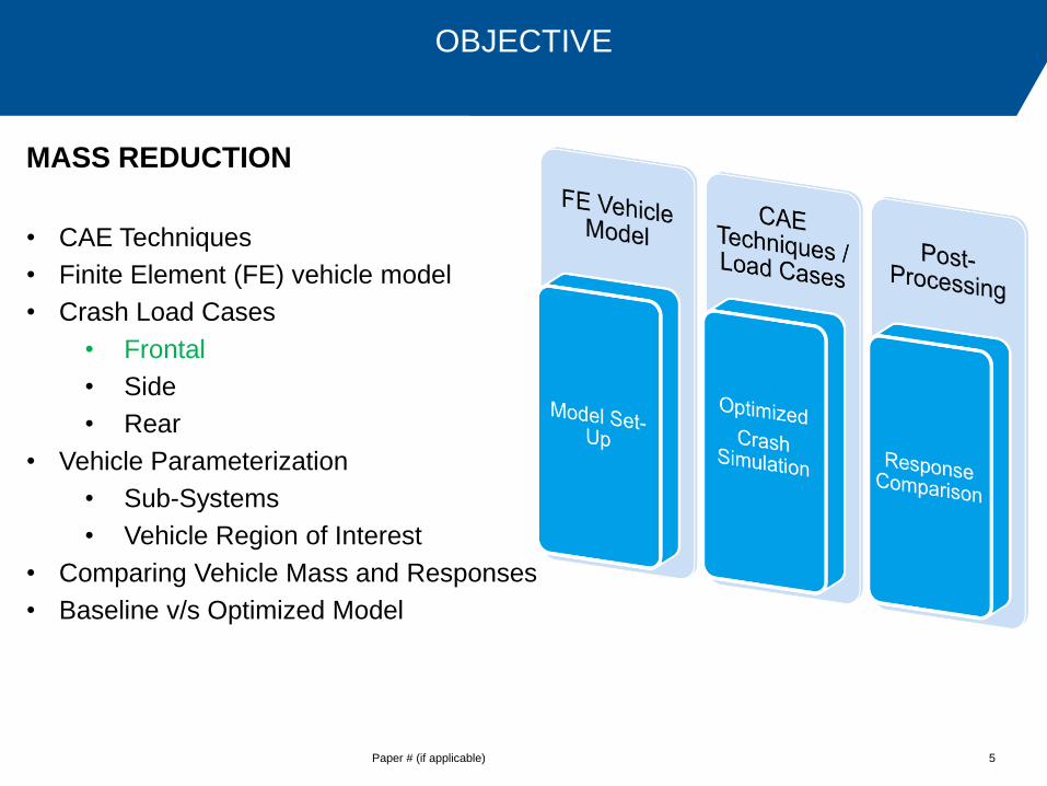
MASS REDUCTION
• CAE Techniques
• Finite Element (FE) vehicle model
• Crash Load Cases
• Frontal
• Side
• Rear
• Vehicle Parameterization
• Sub-Systems
• Vehicle Region of Interest
• Comparing Vehicle Mass and Responses
• Baseline v/s Optimized Model
OBJECTIVE
Paper # (if applicable) 5
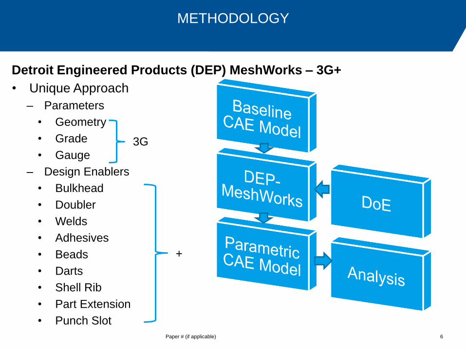
Detroit Engineered Products (DEP) MeshWorks – 3G+
• Unique Approach
– Parameters
• Geometry
• Grade
• Gauge
– Design Enablers
• Bulkhead
• Doubler
• Welds
• Adhesives
• Beads
• Darts
• Shell Rib
• Part Extension
• Punch Slot
METHODOLOGY
Paper # (if applicable) 6
3G
+
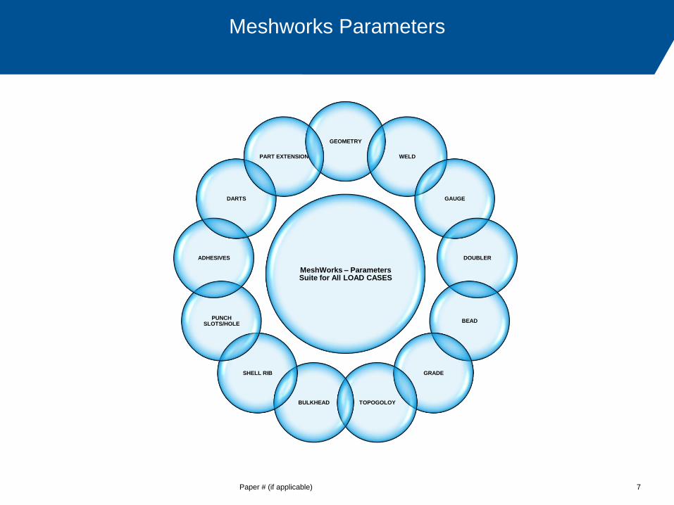
Meshworks Parameters
Paper # (if applicable) 7
MeshWorks – Parameters Suite for All LOAD CASES
GEOMETRY
WELD
GAUGE
DOUBLER
BEAD
GRADE
TOPOGOLOY BULKHEAD
SHELL RIB
PUNCH SLOTS/HOLE
ADHESIVES
DARTS
PART EXTENSION
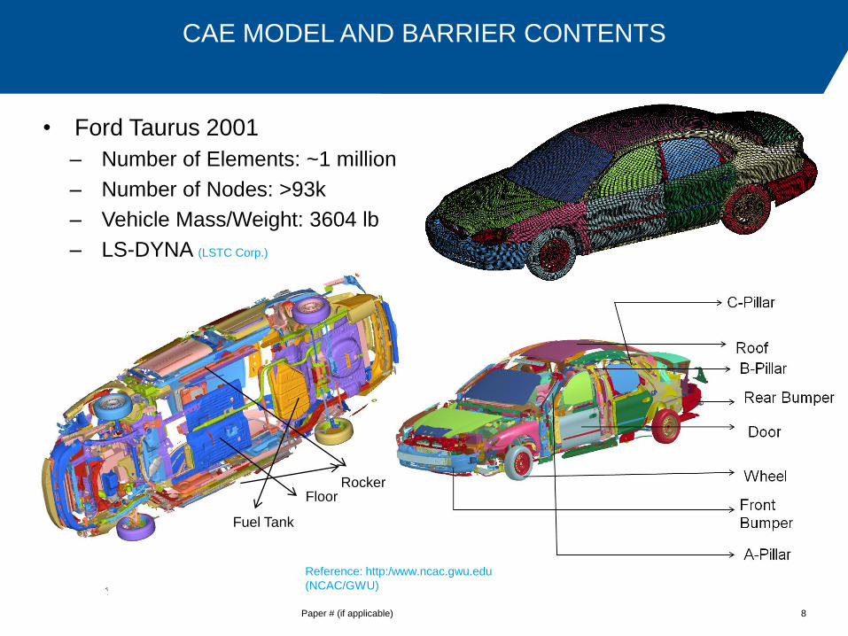
• Ford Taurus 2001
– Number of Elements: ~1 million
– Number of Nodes: >93k
– Vehicle Mass/Weight: 3604 lb
– LS-DYNA (LSTC Corp.)
CAE MODEL AND BARRIER CONTENTS
Paper # (if applicable) 8
Reference: http:/www.ncac.gwu.edu
(NCAC/GWU)
Floor Rocker
Fuel Tank
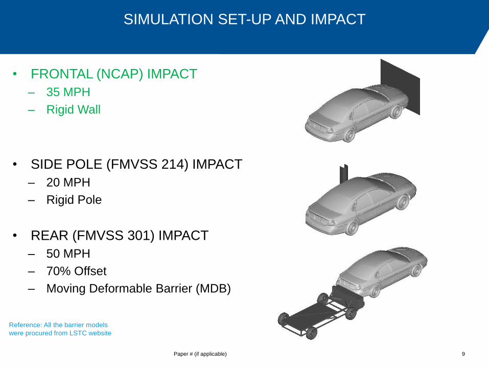
SIMULATION SET-UP AND IMPACT
Paper # (if applicable) 9
• FRONTAL (NCAP) IMPACT
– 35 MPH
– Rigid Wall
• SIDE POLE (FMVSS 214) IMPACT
– 20 MPH
– Rigid Pole
• REAR (FMVSS 301) IMPACT
– 50 MPH
– 70% Offset
– Moving Deformable Barrier (MDB)
Reference: All the barrier models
were procured from LSTC website

• FRONTAL (NCAP) IMPACT
– Vehicle Acceleration at L
Rocker Inner
– Dash Intrusion (Dynamic)
• SIDE POLE (FMVSS 214) IMPACT
– Floor Intrusion
– Beltline Intrusion
• REAR (FMVSS 301) IMPACT
– Fuel tank zone intrusion
– Fuel tank plastic strain
VEHICLE RESPONSES FOR DIFFERENT IMPACT SCENARIOS
Paper # (if applicable) 10

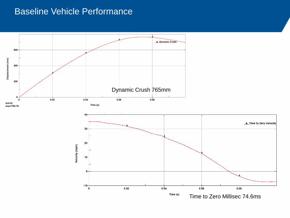
Baseline Vehicle Performance
Paper # (if applicable) 11
Baseline model summary
Dynamic Crush (mm) 765.79
Time to Zero velocity (ms) 74.6
Acceleration Pulse (g) 53.90
Dash Intrusion (mm) 661.41
Baseline Vehicle Performance
Dynamic Crush 765mm
Time to Zero Millisec 74.6ms
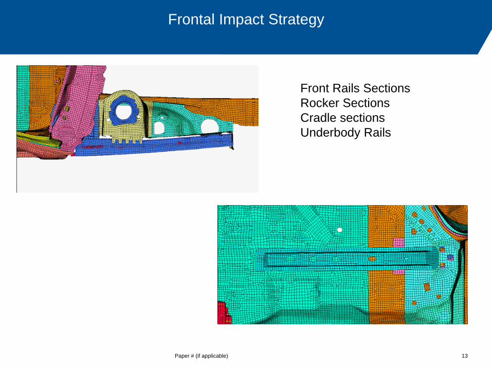
Frontal Impact Strategy
Paper # (if applicable) 13
Front Rails Sections
Rocker Sections
Cradle sections
Underbody Rails

Side/Rear Impact Strategy
Paper # (if applicable) 14

Design Enablers Strategy
Paper # (if applicable) 15
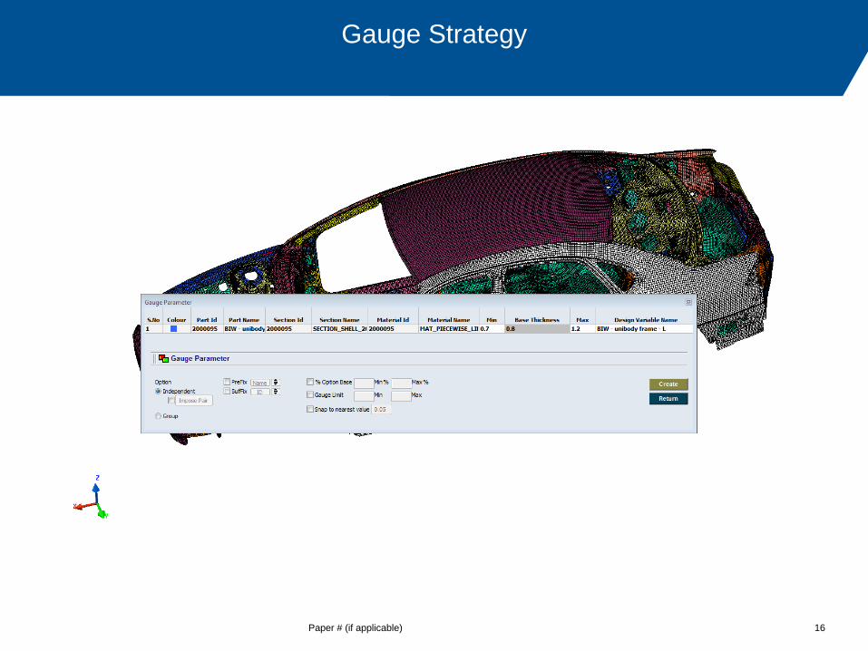
Gauge Strategy
Paper # (if applicable) 16
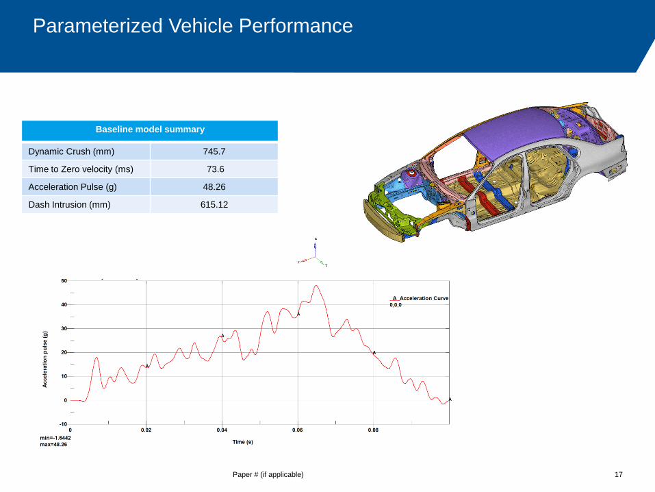
Parameterized Vehicle Performance
Paper # (if applicable) 17
Baseline model summary
Dynamic Crush (mm) 745.7
Time to Zero velocity (ms) 73.6
Acceleration Pulse (g) 48.26
Dash Intrusion (mm) 615.12

Baseline Vehicle Performance
Dynamic Crush 615mm
Time to Zero Millisec 73.6ms

Paper # (if applicable) 19
Next Steps
Parameterization on the vehicle load path and considering them for
the Shape optimization
Applying the High strength steels optimally
Run the optimization considering Front and Side load cases