Embed Size (px)
Citation preview

A W O R L D O F C O M F O R T
V e h i c l e h e at e r s | P R O D u C T i n F O R M AT i O n
VEHiCLE HEATERS, ADDiT iOnAL PARTS, inSTALLATiOn T iPS AnD TECHniCAL DATA

TAbLE OF COnTEnTS
1 heating systems
HEATing SySTEMS – AiR OR WATER 5
Hydronic – WATER HEATERS 6
AiRTROniC – AiR HEATERS 7
2 hyDrOnic
TECHnOLOgy 8 – 11
DEViCE OVERViEW 12 – 15
DEViCE RAngE 16
VEHiCLE-SPECiFiC ADDiTiOnAL PARTS 17
DOMPLETE PACkAgES / uniVERSAL inSTALLATiOn kiTS 18
PARTS RAngE 20 – 22
COnTROL uniTS 23 – 25
OPTiOnAL ADD-OnS 26 – 33
3 airtrOnic
TECHnOLOgy 34
DEViCE OVERViEW 35 – 36
DEViCE RAngE 37 – 39
inSTALLATiOn PARTS 40 – 55
COnTROL uniTS 56 – 57
OPTiOnAL ADD-OnS 58 – 59
4 serVice
EASySCAn DiAgnOSTiC AnD SERViCE TOOL 60 – 61
OTHER DiAgnOSTiC DEViCES 62
TESTing EquiPMEnT 63
SERViCE / REPLACEMEnT DEViCE PROgRAM 64
REPLACEMEnT DEViCES PROgRAM 65
ADDiTiOnAL HEATERS / OEM HEATERS 66
5 fan cOntrOl
FAn & FLAP MODuLE EASyFAn 67 – 68
A/C kiT WiTH iPCu FOR COnTROLLing THE VEHiCLE'S FAn 69
6 the benefits
THE bEnEFiTS FOR WORkSHOPS 70
THE bEnEFiTS FOR EnD CuSTOMERS 72 – 73
2 | P R O D u C T i n F O R M A T i O n
accessOries
7 WATER-COnDuCTing PARTS 76 – 81
8 AiR-COnDuCTing PARTS 83 – 91
9 FuEL-COnDuCTing PARTS 92 – 98
10 ELECTRiCAL PARTS / TESTing EquiPMEnT 99 – 113
11 ExHAuST-COnDuCTing AnD COMbuSTiOn-AiR-COnDuCTing PARTS 116 – 123
12 FASTEning PARTS 124 – 133
13 nAME PLATES / inFORMATiOn SignS 134 – 136
14 ADDiTiOnAL PRODuCTS – COnVECTORS AnD inDiViDuAL DEViCES 137 – 145
P R O D u C T i n F O R M A T i O n | 3

1
2
3
4
5
6
7
8
9
10
11
12
13
14
4 | P R O D u C T i n F O R M A T i O n

1
2
3
4
5
6
7
8
9
10
11
12
13
14
1 | HEATing SySTEMS – AiR OR WATER?
The basic principle of pre-heaters is to heat the passenger compartment of all kinds of vehicles without having to depend on the heat given
off by a running engine. That's a well-known fact. But at some point or other you must have asked yourself what the actual difference is
between air and water heaters.
AiR-bASED PRE-HEATERS – EbERSPäCHER AiRTROniC:
Air-based pre-heaters are mostly installed inside the cab and
directly heat the air inside it, which is sucked in via the unit's own
fan. Their effects are noticeable almost instantly, as the heat in
the form of hot gas, which is produced by a burner, does not have
to heat up a water circuit first. Modern devices are very quiet, low
on emissions and chiefly used to maintain the temperature in the
cab of a truck or transporter at a pleasant level even while it is at
a standstill (e.g. overnight).
WATER-bASED PRE-HEATERS – EbERSPäCHER HyDROniC:
Water-based pre-heaters have a compact design and can be fitted
almost anywhere in the engine compartment. They are therefore
the pre-heater of choice for cars with interiors too cramped
for additional installations. The heat generated by a burner is
transferred to the vehicle's cooling water. An (additional) electric
circulation pump distributes the heat, even when the engine is
switched off. Then, the interior fan is activated automatically –
everything works as it does in normal heater operation. Water-
based heaters therefore not only warm up the interior, but also
heat the engine or the water used in boats or motor homes.
Engines heated in this way can be started more easily in cold
weather while also protecting the car battery from the effects of
the cold, and producing fewer harmful emissions on starting, as
the hotter exhaust temperature enables the catalytic converter to
reach its operating temperature more quickly. The cold-starting
phase, which produces mechanical stress and higher emissions, is
dramatically reduced, as the oil reaches operating temperature fast
when the engine is started. This saves fuel and money on the one
hand, and lowers CO2 emissions on the other.
both systems generally run on the vehicle's fuel, straight out of the
fuel tank. Depending on the model, heaters can be activated with a
timer switch, radio remote control or cellphone.
P R O D u C T i n F O R M A T i O n | 5

1
2
3
4
5
6
7
8
9
10
11
12
13
14
HyDROniC 4 kW:
Cab and engine heater
Passenger cars (up to 2.0 l displacement)
Emergency vehicles
Station wagons (with additional thermo-combi valve if using
Hydronic 4; ideally use Hydronic 5)
Small agricultural and construction machinery
Motor yachts up to around 22 ft long*
HyDROniC 5 kW:
Cab and engine heater
Passenger cars, station wagons (up to 2.5 l displacement;
for 2.6 l displacement or greater we always recommend the
Hydronic 2 Comfort)
Emergency vehicles
Vans, large taxis, minivans
Commercial vehicles, including tandem configurations with
air heaters
Construction and agricultural machines
Motor yachts up to around 25 ft long
Motor homes*
HyDROniC M8 / M10 / M12:
Commercial vehicles from approx. 150 kw engine power
Cargo area heating
Military vehicles
Large agricultural and construction machinery
Motor yachts up to approx. 45 ft long
Motor homes
HyDROniC L16 / L24 / L30 / L35:
Coaches and city buses
Large freight compartments for goods which need to be
kept warm
Container setups
Diesel locomotives
yachts and ships up to approx. 72 ft long
1 | HEATing SySTEMS: HyDROniC – WATER HEATERS
* The heater is approved for mains operation (230 V/50 Hz), e.g. in camping or parking areas for motor homes or in marinas for boats, only in combination with a special cable harness (order no.: 25 2652 82 11 00, see p.108). The cable harness is included in the universal installation kit for recreational vehicles and boats (order no.: 25 2652 82 00 00).
6 | P R O D u C T i n F O R M A T i O n

1
2
3
4
5
6
7
8
9
10
11
12
13
14
AiRTROniC D2:
Heating comfort for a variety of applications.
Truck cabs with sleeping cabins
Construction and agricultural machinery without engine-
dependent heating
Forklifts and other plant machinery
Electric vehicles
yachts up to approx. 22 ft long
AiRTROniC D4 / D4 PLuS / b4:
The high-performance, compact air heater for mid-range requirements.
Large trucks – cabs with sleeping cabins
Vans, small buses
Large agricultural and construction machinery
yachts up to approx. 35 ft long
AiRTROniC D3:
For demanding long-term heating requirements.
quiet and energy-saving.
Motor homes
Minivans, and vehicles used for conferences and
consultancy
Large truck / luxury cabs with sleeping cabins
AiRTROniC D5 / b5:
TRS-enabled, continuously variable, pre-selectable interior
temperature regulation.
Vans, workshop vehicles and personnel carriers, small
buses (fast heating despite door opening frequently)
Ambulances and emergency medics' vehicles
special heating and temperature requirements
Freight compartment and freight goods heating plus
frost protection and dew point prevention
yachts and ships up to approx. 45 ft long
D8 LC:
Continuously variable, pre-selectable interior temperature
regulation.
Large freight compartments, containers
Personnel carriers
Coaches and city buses
Ships up to around 62 ft long
1 | HEATing SySTEMS: AiRTROniC – AiR HEATERS
P R O D u C T i n F O R M A T i O n | 7
1
2
3
4
5
6
7
8
9
10
11
12
13
14
8 | P R O D u C T i n F O R M A T i O n
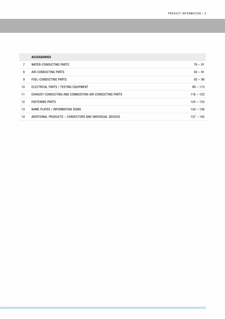
2 | HyDROniC S3 ECOnOMy: TECHnOLOgy
HyDROniC S3 ECOnOMy* FunCTiOnS:
Combustion air is conveyed to the combustion chamber by the fan motor and impeller.
Fuel is drawn from the vehicle's tank.
Fuel is conveyed to the combustion chamber by the metering pump (reciprocating pump).
The glow element vaporizes this fuel as it enters the combustion chamber and creates a combustible fuel-air mix with the combustion air.
The resulting flame formation switches off the glow element, transfers the heat to the cooling water via the convector, and diverts exhaust
gas via the exhaust silencer.
The cooling water circulation pump conveys cool water to the heater, where it is warmed by the convector and then routed to the vehicle's
convector and combustion engine.
Control module
Combustion airinlet
Warm water outlet
Combustion-air fan
Fuel fitting / supply
Always install the metering pump with the back pointing upward – optimum installation position 15° – 35°
Engine-independent heatfor all vehicles
Cold-water inlet
Water pump
Fuel metering pump
Exhaust-gas outlet
Exhaust silencer
glow element
Electric motor Combustion chamber
Convector
Water outlet sensor
Water outlet sensor
* The heater is approved for mains operation (230 V/50 Hz), e.g. in camping or parking areas for motor homes or in marinas for boats, only in combination with a special cable harness (order no.: 25 2652 82 11 00, see p.108). The cable harness is included in the universal installation kit for recreational vehicles and boats (order no.: 25 2652 82 00 00).

1
2
3
4
5
6
7
8
9
10
11
12
13
14
P R O D u C T i n F O R M A T i O n | 9
2 | HyDROniC 2 COMFORT: TECHnOLOgy
HyDROniC 2 COMFORT FunCTiOnS:
See Hydronic functions (page opposite)
The Hydronic 2 Comfort has an inbuilt thermostat valve in the comfort circuit which ensures that the vehicle interior is warmed first.
When the cooling water temperature is at least 67°C the valve then opens the wider circuit in order to route heat to the vehicle's
combustion engine. by this point the vehicle interior has already reached a temperature which enables the windows to thaw completely.
The Hydronic 2 Comfort is therefore absolutely ideal for short-distance car drivers, as the short heating time puts less load on the vehicle
battery.
Switching element
Control module
Convector
Combustion chamber
Fuel-metering pump
glow element
Combustion airinlet
Warm-water outlet
to the engine
Combustion-air fan
Fuel fitting / supply
Cold-water inlet
Water pump
Overheating control sensor
Exhaust-gas outlet
Warm-water outlet to the convector
Surface sensor
Exhaust silencer

1
2
3
4
5
6
7
8
9
10
11
12
13
14
1 0 | P R O D u C T i n F O R M A T i O n
2 | HyDROniC M: TECHnOLOgy
HyDROniC M FunCTiOnS:
Combustion air is conveyed to the combustion chamber by the fan motor and impeller.
Fuel is drawn from the vehicle's tank.
Fuel is conveyed to the combustion chamber by the metering pump (reciprocating pump).
The glow element vaporises this fuel as it enters the combustion chamber and creates a combustible fuel-air mix with the combustion air.
The resulting flame formation switches off the glow element, transfers the heat to the cooling water via the convector, and diverts exhaust
gas via the exhaust silencer.
The cooling water circulation pump conveys cool water to the heater, where it is warmed by the convector and then routed to the vehicle's
own convector and combustion engine.
Overheating sensor
glow element
Convector
Combustion chamber
Cold-water inlet
Cable loom,Heater
ExhaustOutlet
Fuel fitting / supply
Combustion airinlet
Warm-water outlet
Water pump
Flame sensor
Combustion-air fan
Control module
Fuel metering pump
Exhaust silencer
Electric motor
1
2
3
4
5
6
7
8
9
10
11
12
13
14
P R O D u C T i n F O R M A T i O n | 1 1
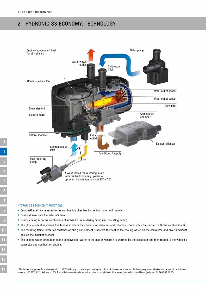
2 | HyDROniC L: TECHnOLOgy
HyDROniC L FunCTiOnS:
Combustion air is conveyed to the combustion chamber by the fan motor and impeller.
A gear pump conveys fuel from the vehicle's tank and builds up pressure against the closed solenoid valve.
The solenoid valve opens and the fuel is atomized by the fuel nozzle in the combustion chamber / flame tube.
The ignition spark monitor ignites the fuel-air mix.
The resulting flame detection by an optical flame sensor switches off the ignition spark monitor, transfers the heat to the cooling water via
the convector, and diverts exhaust gas via the exhaust silencer.
The cooling water circulation pump conveys cool water to the heater, where it is warmed by the convector and then routed to the vehicle's
own convector and combustion engine.
Electricmotor
Control modulewith integrated flame monitor
Combustion air inlet
Fuelsupply
Water outletWater inlet
ConvectorCombustionchamber
Fuelnozzle
ignition spark monitor with ignition electrodes
Exhaustoutlet
integrated fuel pump with solenoid valve
Maintenance-optimizedburner tip
Combustion airfan impeller
Temperature sensor
1
2
3
4
5
6
7
8
9
10
11
12
13
14
1 2 | P R O D u C T i n F O R M A T i O n
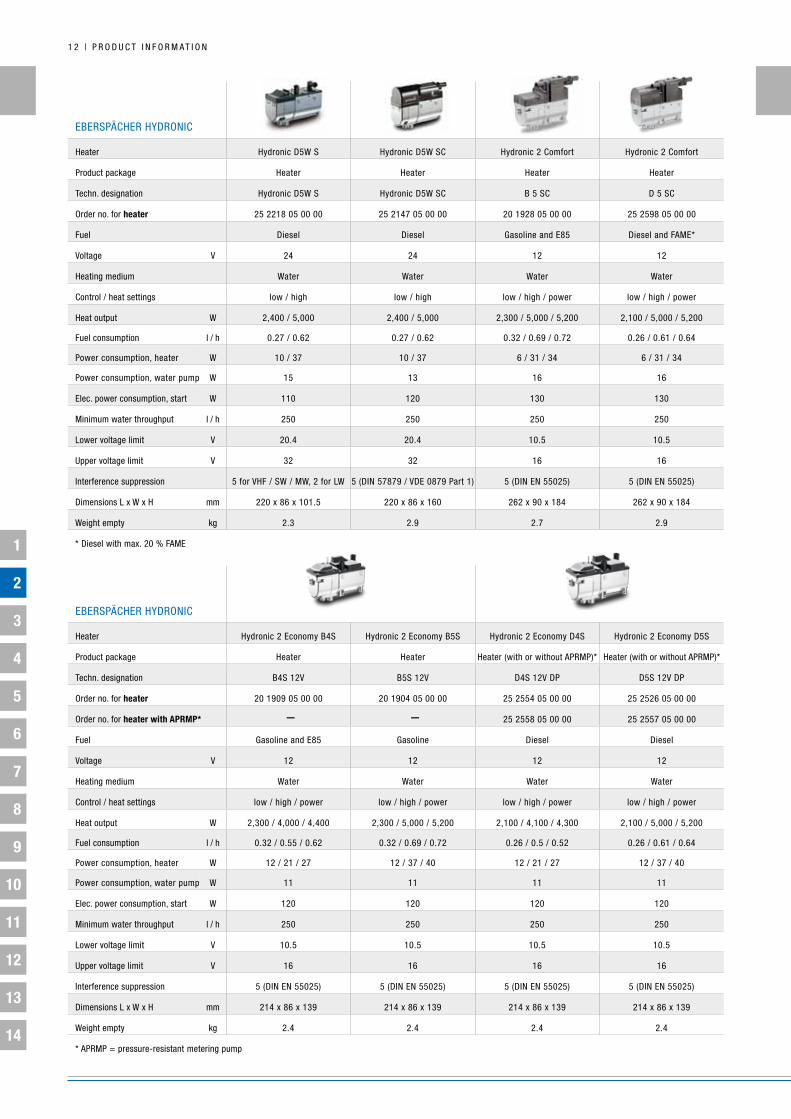
EbERSPäCHER HyDROniC
Heater Hydronic D5W S Hydronic D5W SC Hydronic 2 Comfort Hydronic 2 Comfort
Product package Heater Heater Heater Heater
Techn. designation Hydronic D5W S Hydronic D5W SC b 5 SC D 5 SC
Order no. for heater 25 2218 05 00 00 25 2147 05 00 00 20 1928 05 00 00 25 2598 05 00 00
Fuel Diesel Diesel gasoline and E85 Diesel and FAME*
Voltage V 24 24 12 12
Heating medium Water Water Water Water
Control / heat settings low / high low / high low / high / power low / high / power
Heat output W 2,400 / 5,000 2,400 / 5,000 2,300 / 5,000 / 5,200 2,100 / 5,000 / 5,200
Fuel consumption l / h 0.27 / 0.62 0.27 / 0.62 0.32 / 0.69 / 0.72 0.26 / 0.61 / 0.64
Power consumption, heater W 10 / 37 10 / 37 6 / 31 / 34 6 / 31 / 34
Power consumption, water pump W 15 13 16 16
Elec. power consumption, start W 110 120 130 130
Minimum water throughput l / h 250 250 250 250
Lower voltage limit V 20.4 20.4 10.5 10.5
upper voltage limit V 32 32 16 16
interference suppression 5 for VHF / SW / MW, 2 for LW 5 (Din 57879 / VDE 0879 Part 1) 5 (Din En 55025) 5 (Din En 55025)
Dimensions L x W x H mm 220 x 86 x 101.5 220 x 86 x 160 262 x 90 x 184 262 x 90 x 184
Weight empty kg 2.3 2.9 2.7 2.9
* Diesel with max. 20 % FAME
EbERSPäCHER HyDROniC
Heater Hydronic 2 Economy b4S Hydronic 2 Economy b5S Hydronic 2 Economy D4S Hydronic 2 Economy D5S
Product package Heater Heater Heater (with or without APRMP)* Heater (with or without APRMP)*
Techn. designation b4S 12V b5S 12V D4S 12V DP D5S 12V DP
Order no. for heater 20 1909 05 00 00 20 1904 05 00 00 25 2554 05 00 00 25 2526 05 00 00
Order no. for heater with aPrmP* – – 25 2558 05 00 00 25 2557 05 00 00
Fuel gasoline and E85 gasoline Diesel Diesel
Voltage V 12 12 12 12
Heating medium Water Water Water Water
Control / heat settings low / high / power low / high / power low / high / power low / high / power
Heat output W 2,300 / 4,000 / 4,400 2,300 / 5,000 / 5,200 2,100 / 4,100 / 4,300 2,100 / 5,000 / 5,200
Fuel consumption l / h 0.32 / 0.55 / 0.62 0.32 / 0.69 / 0.72 0.26 / 0.5 / 0.52 0.26 / 0.61 / 0.64
Power consumption, heater W 12 / 21 / 27 12 / 37 / 40 12 / 21 / 27 12 / 37 / 40
Power consumption, water pump W 11 11 11 11
Elec. power consumption, start W 120 120 120 120
Minimum water throughput l / h 250 250 250 250
Lower voltage limit V 10.5 10.5 10.5 10.5
upper voltage limit V 16 16 16 16
interference suppression 5 (Din En 55025) 5 (Din En 55025) 5 (Din En 55025) 5 (Din En 55025)
Dimensions L x W x H mm 214 x 86 x 139 214 x 86 x 139 214 x 86 x 139 214 x 86 x 139
Weight empty kg 2.4 2.4 2.4 2.4
* APRMP = pressure-resistant metering pump
1
2
3
4
5
6
7
8
9
10
11
12
13
14
P R O D u C T i n F O R M A T i O n | 1 3
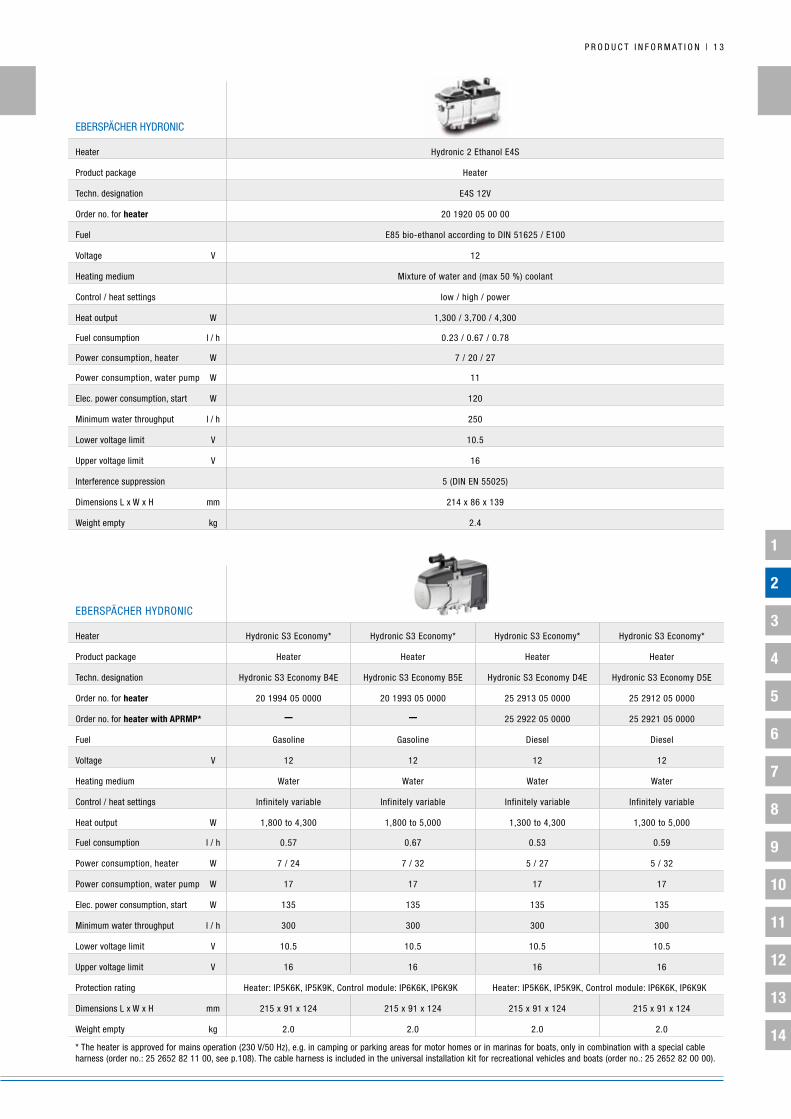
EbERSPäCHER HyDROniC
Heater Hydronic S3 Economy* Hydronic S3 Economy* Hydronic S3 Economy* Hydronic S3 Economy*
Product package Heater Heater Heater Heater
Techn. designation Hydronic S3 Economy b4E Hydronic S3 Economy b5E Hydronic S3 Economy D4E Hydronic S3 Economy D5E
Order no. for heater 20 1994 05 0000 20 1993 05 0000 25 2913 05 0000 25 2912 05 0000
Order no. for heater with aPrmP* – – 25 2922 05 0000 25 2921 05 0000
Fuel gasoline gasoline Diesel Diesel
Voltage V 12 12 12 12
Heating medium Water Water Water Water
Control / heat settings infinitely variable infinitely variable infinitely variable infinitely variable
Heat output W 1,800 to 4,300 1,800 to 5,000 1,300 to 4,300 1,300 to 5,000
Fuel consumption l / h 0.57 0.67 0.53 0.59
Power consumption, heater W 7 / 24 7 / 32 5 / 27 5 / 32
Power consumption, water pump W 17 17 17 17
Elec. power consumption, start W 135 135 135 135
Minimum water throughput l / h 300 300 300 300
Lower voltage limit V 10.5 10.5 10.5 10.5
upper voltage limit V 16 16 16 16
Protection rating Heater: iP5k6k, iP5k9k, Control module: iP6k6k, iP6k9k Heater: iP5k6k, iP5k9k, Control module: iP6k6k, iP6k9k
Dimensions L x W x H mm 215 x 91 x 124 215 x 91 x 124 215 x 91 x 124 215 x 91 x 124
Weight empty kg 2.0 2.0 2.0 2.0
* The heater is approved for mains operation (230 V/50 Hz), e.g. in camping or parking areas for motor homes or in marinas for boats, only in combination with a special cable harness (order no.: 25 2652 82 11 00, see p.108). The cable harness is included in the universal installation kit for recreational vehicles and boats (order no.: 25 2652 82 00 00).
EbERSPäCHER HyDROniC
Heater Hydronic 2 Ethanol E4S
Product package Heater
Techn. designation E4S 12V
Order no. for heater 20 1920 05 00 00
Fuel E85 bio-ethanol according to Din 51625 / E100
Voltage V 12
Heating medium Mixture of water and (max 50 %) coolant
Control / heat settings low / high / power
Heat output W 1,300 / 3,700 / 4,300
Fuel consumption l / h 0.23 / 0.67 / 0.78
Power consumption, heater W 7 / 20 / 27
Power consumption, water pump W 11
Elec. power consumption, start W 120
Minimum water throughput l / h 250
Lower voltage limit V 10.5
upper voltage limit V 16
interference suppression 5 (Din En 55025)
Dimensions L x W x H mm 214 x 86 x 139
Weight empty kg 2.4

1
2
3
4
5
6
7
8
9
10
11
12
13
14
1 4 | P R O D u C T i n F O R M A T i O n
EbERSPäCHER HyDROniC
Heater Hydronic M8 biodiesel Hydronic M8 biodiesel Hydronic M10 Hydronic M10
Product package Heater Heater Heater Heater
Techn. designation Hydronic M-ii (D8W) Hydronic M-ii (D8W) Hydronic M-ii (D10W) Hydronic M-ii (D10W)
Order no. for heater 25 2470 05 00 00 25 2471 05 00 00 25 2434 05 00 00 25 2435 05 00 00
Fuel Diesel and FAME (biodiesel) Diesel and FAME (biodiesel) Diesel Diesel
Voltage V 12 24 12 24
Heating medium Water Water Water Water
Control / heat settings low / medium / high / power low / medium / high / power low / medium / high / power low / medium / high / power
Heat output W 1,500 / 3,500 / 5,000 / 8,000 1,500 / 3,500 / 5,000 / 8,000 1,500 / 3,500 / 8,000 / 9,500 1,500 / 3,500 / 8,000 / 9,500
Fuel consumption l / h 0.18 / 0.4 / 0.65 / 0.9 0.18 / 0.4 / 0.65 / 0.9 0.18 / 0.4 / 0.9 / 1.2 0.18 / 0.4 / 0.9 / 1.2
Power consumption, heater W 6 / 10 / 17 / 26 6 / 10 / 17 / 26 6 / 10 / 31 / 57 6 / 10 / 31 / 57
Power consumption, water pump W 29 29 29 29
Elec. power consumption, start W 200 200 120 120
Minimum water throughput l / h 500 500 500 500
Lower voltage limit V 10 20 10 20
upper voltage limit V 15 30 15 30
interference suppression 5 (Din En 55025) 5 (Din En 55025) 5 (Din En 55025) 5 (Din En 55025)
Dimensions L x W x H mm 331 x 138 x 221 331 x 138 x 221 331 x 138 x 221 331 x 138 x 221
Weight empty kg 6.2 6.2 6.2 6.2
EbERSPäCHER HyDROniC
Heater Hydronic M12 Hydronic M12
Product package Heater Heater
Techn. designation Hydronic M-ii (D12W) Hydronic M-ii (D12W)
Order no. for heater 25 2472 05 00 00 25 2473 05 00 00
Fuel Diesel Diesel
Voltage V 12 24
Heating medium Water Water
Control / heat settings low / medium 1 / medium 2 / medium 3 / high / power low / medium 1 / medium 2 / medium 3 / high / power
Heat output W 1,200 / 1,500 / 3,500 / 5,000 / 9,500 / 12,000 1,200 / 1,500 / 3,500 / 5,000 / 9,500 / 12,000
Fuel consumption l / h 0.15 / 0.18 / 0.4 / 0.65 / 1.2 / 1.5 0.15 / 0.18 / 0.4 / 0.65 / 1.2 / 1.5
Power consumption, heater W 5 / 6 / 10 / 17 / 57 / 103 5 / 6 / 10 / 17 / 57 / 103
Power consumption, water pump W 29 29
Elec. power consumption, start W 120 120
Minimum water throughput l / h 500 500
Lower voltage limit V 10 20
upper voltage limit V 15 30
interference suppression 5 (Din En 55025) 5 (Din En 55025)
Dimensions L x W x H mm 331 x 138 x 221 331 x 138 x 221
Weight empty kg 6.2 6.2

1
2
3
4
5
6
7
8
9
10
11
12
13
14
P R O D u C T i n F O R M A T i O n | 1 5
EbERSPäCHER WATER
PuMPS FOR HyDROniC L
Water pumps Flowtronic 5000 Flowtronic 5000 S Flowtronic 6000 SC
Order no. for water pump 25 2488 26 00 00 25 1818 30 00 00 25 2488 25 00 00
CoolantWater-glycol mix with up to max 50 % glycol
Water-glycol mix with up to max 50 % glycol
Water-glycol mix with up to max 50 % glycol
Delivery rate l / h 5,200 at 0.2 bar 5,200 at 0.2 bar 6,000 at 0.4 bar
Operating pressure bar max. 2 max. 2 max. 2
nominal voltage V 24 24 24
Elec. power consumption W 104 104 210
Protection class iP5k4 iP54A iP25 (potted electronics)
Dry running no no yes – motor switches itself off after 45 minutes
Shaft-impeller connector Mechanical seal Magnetic coupling Magnetic coupling
Weight empty* kg 2.04 2.2 2.5
EbERSPäCHER HyDROniC
Heater Hydronic L16 Hydronic L24 Hydronic L30 Hydronic L35
Product package Heater Heater Heater Heater
Techn. designation Hydronic L-ii (HL2-16) Hydronic L-ii (HL2-24) Hydronic L-ii (HL2-30) Hydronic L-ii (HL2-35)
Order no. for heater 25 2486 02 00 00 25 2487 02 00 00 25 2599 02 00 00 25 2600 02 00 00
Order no. for compact heater – 25 2487 05 00 00 25 2599 05 00 00 25 2600 05 00 00
Fuel Diesel and fuel oil Diesel and fuel oil Diesel and fuel oil Diesel and fuel oil
Voltage V 24 24 24 24
Heating medium Water Water Water Water
Heat output W 16,000 24,000 30,000 35,000
Fuel consumption l / h 2 2.9 3.65 4.2
Power consumption, heater W 60 80 105 120
Power consumption, water pump W 104 – 210* 104 – 210* 104 – 210* 104 – 210*
Minimum water throughput l / h 1,400 2,000 2,600 3,000
Lower voltage limit V 20 20 20 20
upper voltage limit V 30 30 30 30
Dimensions L x W x H mm 600 x 230 x 222 600 x 230 x 222 600 x 230 x 222 600 x 230 x 222
Weight empty** kg 18 18 18 18
* depending on the water pump model

1
2
3
4
5
6
7
8
9
10
11
12
13
14
1 6 | P R O D u C T i n F O R M A T i O n
2 | WATER-HEATER RAngE FOR CARS
ADVAnTAgES:
Hydronic S3 Economy: new bracket design plus straight and 90°
angled water fittings (rotatable through 360°) which can be used in any
combination for faster installation. new installation recommendations
and kits are available.
Hydronic 2 Economy APRMP (pressure-resistant metering pump):
Faster installation as there is no need to remove the tank. Please see
the relevant installation recommendations, plus optional add-ons on
page 24, for the range of cars for which this equipment is suitable.
Hydronic 2 Comfort: Faster installation if thermal management is
required. There is no need to install a separate comfort installation kit.
The biodiesel M8, Standard M10 and Hydronic M12 provide increased
power for larger engines and cabins, e.g. large trucks, small buses,
cargo areas.
The Hydronic L, 16 – 35 kW, is ideally suited for buses, trains, boats
and cargo areas.
FuEL COMPATibiLiTy:
Multifuel E85: The Hydronic 2 b5S and b5SC with fuel kit (E85 kit) for
heating electric vehicles and multifuel vehicles; fuel kit order number 22
1000 20 31 00.
Biodiesel: Hydronic S3 Economy (up to 30 %), Hydronic 2 Economy
(up to 20 %), Hydronic 2 Comfort (up to 20 %), Hydronic (up to 10 %),
Hydronic M8 (100 %), Hydronic M10 / M12 (up to 20 %).
E10: all (professionally installed) water heaters.
ExpErt tips for installing thE prEssurE-rEsistant mEtEring
pump: You need to know the fuel pressure and temperature. the end
of the fuel return line must be just above the floor of the tank and
must not be fitted with a check valve. Diesel vehicles can then be
connected straight to the return line. please also always take note of
the technical description of the particular equipment.
Displacement
from 2.6 l
up to 2.5 l
up to 2.0 l
HyDROniC5 kW heating outputwith thermal manage-ment
HyDROniC4 kW heating output
HyDROniC 5 kW heating output
MiDSizE CLASSCOMPACT SuV
uPPER CLASSSuV
LARgE inTERiORSMiCRO-CARS AnD SMALL CARS
COMPACT CARS

1
2
3
4
5
6
7
8
9
10
11
12
13
14
P R O D u C T i n F O R M A T i O n | 1 7
Heater
• Contents
• Heater
• Water pump
• Metering pump
Vehicle-specific installation kit
• Heater mounting bracket
• Water hoses
• Fuel lines
• Cable harnesses
• Combustion-air hose• Exhaust hose with silencer
and if applicable, A/C kit
EasyFan / A/C kit
• Cable harness
• Preconfigured cable harness
• Relay
• iPCu (see also Service, options with iPCu, if there is no EasyFan / A/C kit)
Control unit • Easy Start Select / Timer /
Remote / Remote+ / EasyStart Web
2 | VEHiCLE-SPECiFiC ADDiTiOnAL PARTS
The product package for individual devices generally includes the heater itself, the fuel-metering pump and the water pump. For
retrofitting vehicles for which Eberspächer provides installation recommendations, a vehicle-specific installation kit (IK) and, if
applicable, an air-conditioning kit are also required.
iMAgES ARE FOR iLLuSTRATiVE PuRPOSES OnLy

1
2
3
4
5
6
7
8
9
10
11
12
13
14
1 8 | P R O D u C T i n F O R M A T i O n
2 | COMPLETE PACkAgES / uniVERSAL inSTALLATiOn kiTS
The following table shows the housing types and product packages of the various water heater models along with their corresponding
installation kits. in contrast with individual devices, complete packages include the heater (incl. fuel-metering and water pump) and universal
installation kit. The universal installation kit includes a host of (vehicle independent) parts required for installation. in this case, additional
vehicle-specific installation parts are required which are not listed in the respective installation recommendations. if Eberspächer provides no
installation recommendations for a particular vehicle, you can still retrofit a pre-heater using a complete package (see also the next section,
“Hydronic – retrofit parts range for passenger cars”, step 4b). S-models have a space-saving housing design, with the fuel-metering and
water pump mounted on the outside. SC-models generally have the water pump on the inside of the equipment, and on diesel heaters the
fuel-metering pump is also on the inside. For gasoline versions the fuel-metering pump is generally installed on the outside.
Water heaters Heater individual devices Complete packageVehicle-specific ik
A/C kit if applicableuniversal ik
Hydronic
25 2218 05 00 00 x 25 2218 80 00 00
25 2147 05 00 00 x 25 2009 80 00 00
20 1861 05 00 0020 1663 05 00 00
xx
25 2418 05 00 0025 2386 05 00 00
xx
25 2385 05 00 0025 2390 05 00 00
xx
Hydronic 2Economy
25 2558 05 00 0025 2554 05 00 0025 2557 05 00 0025 2526 05 00 0020 1909 05 00 0020 1904 05 00 00
xxxxxx
xx xxxx
25 2526 81 00 00
Hydronic 2 Ethanol E4S
20 1920 05 00 00xx
xx
20 1920 82 00 0020 1920 83 00 00**
Hydronic 2Comfort
20 1928 05 00 0025 2598 05 00 00
xx
xx
25 2598 80 00 00
Hydronic S3 Economy*
20 1963 05 00 0020 1952 05 00 0025 2694 05 00 0025 2652 05 00 00
xxxx
xxxx
25 2652 80 00 00
Hydronic M2
25 2470 05 00 0025 2471 05 00 0025 2434 05 00 0025 2435 05 00 0025 2472 05 00 0025 2473 05 00 00
xxxxxx
25 2435 81 00 00
* The heater is approved for mains operation (230 V/50 Hz), e.g. in camping or parking areas for motor homes or in marinas for boats, only in combination with a special cable harness (order no.: 25 2652 82 11 00, see p.108). The cable harness is included in the universal installation kit for recreational vehicles and boats (order no.: 25 2652 82 00 00).** ik with cat.

1
2
3
4
5
6
7
8
9
10
11
12
13
14
P R O D u C T i n F O R M A T i O n | 1 9

1
2
3
4
5
6
7
8
9
10
11
12
13
14
2 0 | P R O D u C T i n F O R M A T i O n
2 | RETROFiT PARTS RAngE FOR PASSEngER CARS
inSTALLATiOn OF THE HyDROniC WATER HEATER / HyDROniC 2 WiTH 4 OR 5 kW HEATing OuTPuT:
1 | LOgging inTO THE PARTnER PORTAL
Log into the Eberspächer Partner Portal with your personal access details (email and password):
http://partner.eberspaecher.com
2 | “inSTALLATiOn inFORMATiOn” PAnE
next, select the “installation information / installation Recommendations” tab.

1
2
3
4
5
6
7
8
9
10
11
12
13
14
P R O D u C T i n F O R M A T i O n | 2 1
HyDROniCPARTS RAngE
3 | SELECTing yOuR VEHiCLE TyPE
using the dropdown menu, select the required vehicle and
confirm with the “Search” button.
EXPERT TIPS4b | THERE iS nO inSTALLATiOn RECOMMEnDATiOn FOR THE VEHiCLE
if there is no installation recommendation, you will see a note to this effect and the installation recommendation will be grayed out.
However, it may still be possible to retrofit an Eberspächer pre-heater in the selected vehicle by using the universal installation kit.
The required installation parts are displayed.
recommended heater
control unit
required installation parts
installation guide time
* Heaters and control units with a black arrow after the price
can be adapted if necessary by clicking the arrow and making
a selection.
4a | THERE iS An inSTALLATiOn RECOMMEnDATiOn FOR THE VEHiCLE
if there is an existing retrofit installation recommendation for the vehicle, the vehicle model will be listed along with the recommended
heater, including the price (excl. sales tax). Click on the vehicle in the list. The parts required for the installation are now displayed:
Recommended heater (including water pump and
fuel metering pump)
control unit
Vehicle-specific installation kit including all parts
required for the mechanical installation
a/c kit if applicable (for models with automatic
air conditioning)
Additional installation parts if applicable
Recommended installation guide time
* Heaters and control units with a black arrow after the price can
be adapted if necessary by clicking the arrow and making a selection.
if you click the “get estimate” button, this will take you to the
estimates pane where you can obtain a quote.

1
2
3
4
5
6
7
8
9
10
11
12
13
14
2 2 | P R O D u C T i n F O R M A T i O n
inSTALLATiOn OF THE HyDROniC M WATER HEATER WiTH 8 – 12 kW
HEATing OuTPuT:
installation parts for the Hydronic-M heaters are usually heavily
application-dependent. Planning installation of these heaters
requires not only the heater and universal installation kit but also,
where applicable, additional installation parts that need to be
determined during installation planning. Please see the section on
“Accessories” for the corresponding additional parts. For example,
with convector and boiler installations, a wide range of heating
options can be used in parallel.
Hydronic-M heater installations generally require the following
parts:
Hydronic M heater with 8 kW, 10 kW or 12 kW output,
12 or 24 V
Hydronic M universal installation kit
Control unit (of your choice)
Additional installation parts based on application, if applicable
(see also “Accessories” section)
See also the sections on “Complete packages / universal installation
kits”, “Device range” and “Control units”.
inSTALLATiOn OF THE HyDROniC L WATER HEATER WiTH 16 – 35 kW
HEATing OuTPuT:
installation parts for the Hydronic L heaters are also heavily
application-dependent. As a result there is no universal installation
kit for these heaters.
Alongside the heater, installation planning needs to include
some additional installation parts which have to be specified
during planning. Please see the section on “Accessories” for the
corresponding additional parts. Again, for example, there is a host
of heating options that can be used in parallel in convector and
boiler installation.
The 24 kW, 30 kW and 35 kW heater variants are available
individually as well as in a compact version. To make heater
installation easier the compact version comes with the water
pump and fuel filter and their installation parts pre-installed.
Hydronic L 16 kW, 24 kW, 30 kW or 35 kW heater as individual
device or compact version
Additional parts for connecting the water circuit
Additional parts for the fuel supply
Additional parts of the exhaust system
Control unit (of your choice)
See also the sections on “Device range” and “Control units”.
2 | RETROFiT PARTS RAngE
Our technical hotline can provide you with advice and
support on this: Phone: 0180 5 26 26 26
1
2
3
4
5
6
7
8
9
10
11
12
13
14
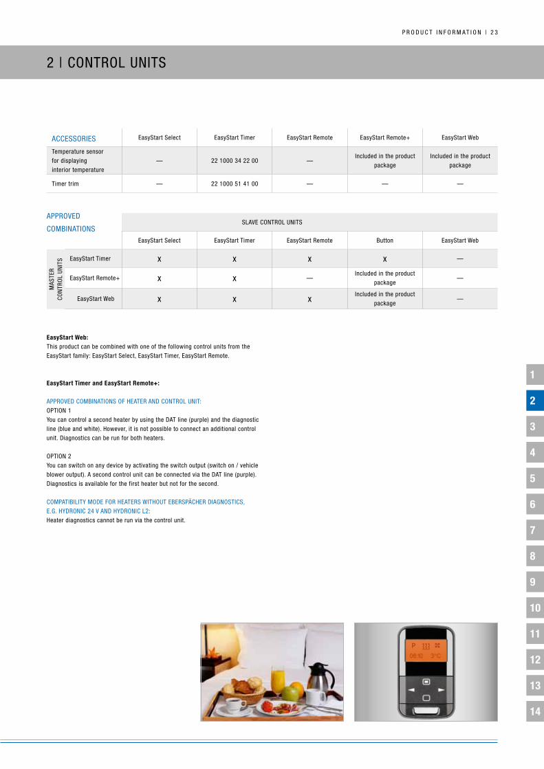
P R O D u C T i n F O R M A T i O n | 2 3
2 | COnTROL uniTS
ACCESSORiES EasyStart Select EasyStart Timer EasyStart Remote EasyStart Remote+ EasyStart Web
Temperature sensorfor displaying interior temperature
— 22 1000 34 22 00 —included in the product
packageincluded in the product
package
Timer trim — 22 1000 51 41 00 — — —
easystart Web:This product can be combined with one of the following control units from the EasyStart family: EasyStart Select, EasyStart Timer, EasyStart Remote.
easystart timer and easystart remote+:
APPROVED COMbinATiOnS OF HEATER AnD COnTROL uniT:OPTiOn 1you can control a second heater by using the DAT line (purple) and the diagnostic line (blue and white). However, it is not possible to connect an additional control unit. Diagnostics can be run for both heaters.
OPTiOn 2you can switch on any device by activating the switch output (switch on / vehicle blower output). A second control unit can be connected via the DAT line (purple). Diagnostics is available for the first heater but not for the second.
COMPATibiLiTy MODE FOR HEATERS WiTHOuT EbERSPäCHER DiAgnOSTiCS, E.g. HyDROniC 24 V AnD HyDROniC L2: Heater diagnostics cannot be run via the control unit.
SLAVE COnTROL uniTS
EasyStart Select EasyStart Timer EasyStart Remote button EasyStart Web
EasyStart Timer x x x x —
EasyStart Remote+ x x —included in the product
package—
EasyStart Web x x xincluded in the product
package—
MAS
TER
CO
nTR
OL
uniT
S
APPROVED
COMbinATiOnS
1
2
3
4
5
6
7
8
9
10
11
12
13
14
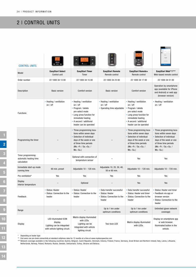
2 4 | P R O D u C T i n F O R M A T i O n
2 | COnTROL uniTS
COnTROL uniTS
Modeleasystart select
Control uniteasystart timer
Timereasystart remote
Remote controleasystart remote+
Remote controleasystart Web**/***
Web-based remote control
Order number 22 1000 34 13 00 22 1000 34 15 00 22 1000 34 23 00 22 1000 34 17 00 22 1000 34 51 00
Description basic version Comfort version basic version Comfort version
Operation by smartphone app (available for iPhone and Android) or web app
(browser version)
Functions
• Heating / ventilation on / off
• Heating / ventilation on / off
• Program / delete pre-select mode
• Long-press function for immediate heating
• A second / additional heater can be operated
• Heating / ventilation on / off
• Operating time adjustable
• Heating / ventilation on / off
• Program / delete pre-select mode
• Long-press function for immediate heating
• A second / additional heater can be operated
• Heating / ventilation on / off
Programming the timer –
• Three programming loca-tions within seven days
• Selection of individual days of the week or one of three time periods (Mo.–Fr. / Sa.+Su. / Mo.–Su.)
–
• Three programming loca-tions within seven days
• Selection of individual days of the week or one of three time periods (Mo.–Fr. / Sa.+Su. / Mo.–Su.)
• Three programming loca-tions within seven days
• Selection of individual days of the week or one of three time periods (Mo.–Fr. / Sa.+Su. / Mo.–Su.)
Timer programming: automatic heating time calculation
– Optional with connection of
temperature sensor – yes yes
immediate start-up mode running time
60 min. preset Adjustable 10 – 120 min.Adjustable 10, 20, 30, 40,
50 or 60 min.Adjustable 10 – 120 min. Adjustable 10 – 720 min.
Pre-ventilation* yes yes yes yes yes
Display interior temperature
– Optional – yes yes
Feedback
• Status: Heater• Status: Connection to the
heater
• Status: Heater• Status: Connection to the
heater
• Data transfer successful• Status: Heater • Status: Connection to the
heater
• Data transfer successful• Status: Heater and timer• Status: Connection to the
heater
• Status: Heater and timer• Feedback via app or
browser version• Status: Connection to the
heater
Range – – up to 1 km under
optimum conditionsup to 1 km under
optimum conditionsunlimited (given network
coverage)
Display
LED-illuminated iCOn display.
Lighting can be integrated with vehicle lighting circuit.
Matrix display illuminated with LEDs.
Lighting can beintegrated with vehicle
lighting circuit.
Two-tone LEDMatrix display illuminated
with LEDs.
Display on smartphone app or web browser.
illuminated button in the vehicle.
* Depending on heater type** End users can pre-book connectivity at standard cellphone rates for 12 months at a time at www.myeberspaecher.com*** network coverage available in the following countries: Austria, belgium, Czech Republic, Denmark, Estonia, Finland, France, germany, great britain and northern ireland, italy, Latvia, Lithuania, netherlands, norway, Poland, Romania, Russia, Sweden, Switzerland, Turkey, ukraine and belarus.

1
2
3
4
5
6
7
8
9
10
11
12
13
14
P R O D u C T i n F O R M A T i O n | 2 5
2 | COnTROL uniTS – EASySTART WEb*
* network coverage available in the following countries: Austria, belgium, Czech Republic, Denmark, Estonia, Finland, France, germany, great britain and northern ireland, italy, Latvia, Lithuania, netherlands, norway, Poland, Romania, Russia, Sweden, Switzerland, Turkey, ukraine and belarus.
1. ADVAnTAgES (FunCTiOnS): Pre-installed SiM chip instead of having to fit a
SiM card integrated antenna in the receiver allows for easy installation Hardware backward compatible with most pre-heaters from 2007
onward Package includes On / Off button with operating display Package includes temperature sensor Remote browser diagnostics available (on approval by end
customer)
2. FuRTHER FEATuRES: use of all available networks for optimum connectivity no need to fit or replace a SiM card Roaming function enables use in other countries without
additional costs Convenient, cost-effective pre-booking of a flat rate for 12
months at a time intuitive operation with newly designed smartphone app Compatibility with all internet-enabled devices via
wireless-optimized browser version Automatic running time calculation undervoltage warning for vehicle battery Current status display (e.g. operational state, interior temperature
and timer) Another control unit from the EasyStart TP7 family can be used in
addition Flexible heater control with the various
control units
TECHniCAL DATA:
Order number 22 1000 34 5100
Dimensions L x W x H (without fastening brackets) mm 66 x 106 x 25
Protection rating iP 40 to iSO 20653
Average standby current draw mA Standby mode < 1
Current draw A During “Call-in” < 0.5
Max. continuous current draw (during operation) mA < 30
Operating temperature °C –40 to +85
Wireless module integrated quad-band gSM module (2g)
Service life Standby mode: > 10 a
During operation: > 6,000 h
button: > 10,000 actuations

1
2
3
4
5
6
7
8
9
10
11
12
13
14
2 6 | P R O D u C T i n F O R M A T i O n
2 | OPTiOnAL ADD-OnS
ADDiTiOnAL HEATER kiT:
Order number: 24 8532 00 0000
Designation: ES additional heater kit for Hydronic 2 with EasyStart
Area of application: Hydronic 2 Economy in combination with
EasyStart
Expands pre-heater functionality for additional heating when driving
(providing added value). The heating is switched on and off based
on the outside temperature when the combustion engine is running.
if the outside temperature is lower than around 5 °C the heating
switches on, and switches off at higher temperatures.
PRE-VEnTiLATiOn OPTiOn:
The Hydronic 12 V and Hydronic 2 Economy and Comfort have a
pre-ventilation function
both this and the EasyStart control units are automatically
detected (see Commissioning EasyStart)
ALTiTuDE kiT*:
Suitable for Hydronic and Hydronic 2 and is required from altitudes
of around 1,500 m. When the heater starts, the pressure sensor
measures the atmospheric pressure cyclically and sends the
measured values to the heater control module. The control module
evaluates the measured values and if required, adjusts the fuel feed
in the metering pump to the current atmospheric pressure. it begins
reducing fuel feed at around 1,400 m, which immediately starts to
reduce heating power by around 9 % for every 1,000 m in altitude.
Check the compatibility of the heater, and pressure sensor and
control unit before installation. (Please look for “H-kit“ on the
heater identification label)
technical data:
max. permissible height: approx. 3,500 m
measuring range: 600 hpa to 1,150 hpa
nominal voltage: 12 / 24 V
operating voltage: 8 to 32 V
Dimensions: 76 x 76 x 29 mm
operating temperature: -40 °C to +85 °C
Fig.: Sticker on heater box
iDEnTiFiCATiOn LAbEL:
1. in this case, on the right-hand side of the heater identification
label you will see “H-kit“. if the label carries this mark, the heater
is suitable for automatic altitude adjustment.
2. The heater's packaging (box) carries a sticker on which you will
find the drawing number of the heater: The last two characters
of this number (e.g. “0n“) specify heater status. based on this
information, the Technical Hotline can tell you whether the heater
is compatible with the altitude kit. if the label is not legible, please
contact the Technical Hotline.
Tech
nica
l Hot
line:
018
05 2
6262
6
* The Hydronic M8, M10 and M12 feature the automatic altitude adjustment function. The heating can be operated up to altitudes of 3,500 m.
Fig.: identification label

1
2
3
4
5
6
7
8
9
10
11
12
13
14
P R O D u C T i n F O R M A T i O n | 2 7
2 | OPTiOnAL WATER CiRCuiTS On A HyDROniC S3 ECOnOMy* ExAMPLE
“inLinE inTEgRATiOn” OF COOLing CiRCuiT:
Cut through the vehicle's water feed hose from the engine and the
convector.
Connect the heater and water pump to the water feed hose using
the connection fittings and water hoses.
Run and connect a water hose from the water pump pressure fitting
to the heater water inlet fitting.
heating characteristic
When the heater is switched on, heat is initially only conveyed to the
vehicle's engine via the vehicle convector.
Once the coolant temperature reaches approx. 30 °C, the vehicle's
fan starts up and heat is supplied to the passenger compartment as
well.
1 Heater
2 Water pump
3 Connecting piece
4 Convector
5 Vehicle engine
COOLing CiRCuiT WiTH CHECk VALVE:
Cut through the vehicle's water feed hose from the engine to the
convector and insert the check valve.
Connect the heater and the water pump and hoses to the check
valve.
Run and connect a water hose from the water pump pressure fitting
to the heater water inlet fitting.
heating characteristic
When the heater is switched on, heat is initially only conveyed to the
vehicle's engine via the vehicle convector.
Once the coolant temperature reaches approx. 30 °C, the vehicle's
fan starts up and heat is supplied to the passenger compartment as
well.
1 Heater
2 Water pump
3 Check valve
4 Convector
5 Vehicle engine
nOTE: ▪ The “cooling circuit with check valve” maintains the effectiveness of the
vehicle heating when the heater is switched off.
▪ The check valve must be ordered separately – see page 80 for order
number.
* The heater is approved for mains operation (230 V/50 Hz), e.g. in camping or parking areas for motor homes or in marinas for boats, only in combination with a special cable harness (order no.: 25 2652 82 11 00, see p.108). The cable harness is included in the universal installation kit for recreational vehicles and boats (order no.: 25 2652 82 00 00).

1
2
3
4
5
6
7
8
9
10
11
12
13
14
2 8 | P R O D u C T i n F O R M A T i O n
inSTALLing A COMbi VALVE WiTH 5 COnnECTiOnS:
Cut the water feed hose running from the vehicle's engine and
convector, and install the combi valve.
Cut through the water return hose from the vehicle's convector and
engine and insert the T-piece.
Connect the heater and water pump and hoses to the combi valve
and T-piece as shown in the drawing.
1 Heater
2 Water pump
3 Combi valve (5 connections)
4 T-piece
5 Vehicle convector
6 Vehicle engine
COOLing CiRCuiT WiTH COMbi VALVE:
Using the 5-connection combi valve
if the water feed and return lines between the vehicle's engine and
convector are installed separately in the engine compartment, the
5-connection combi valve must be used along with a T-piece.
Using the 6-connection combi valve
if the water feed and return lines between the vehicle's engine and
convector are installed in parallel in the engine compartment, the
6-connection combi valve can be used (without a T-piece).
heating characteristic in pre-heating mode – small cooling
circuit:
initially the heat from the heater, at a coolant temperature of
approximately 67 °C, is conveyed only to the vehicle convector,
rapidly heating the vehicle interior.
Once the coolant temperature reaches around 67 °C, some of the
heat from the heater is also conveyed to the engine. This allows the
engine to be pre-heated while preventing the “small cooling circuit”
for interior heating from cooling too fast.
heating characteristic in additional heating mode – large
cooling circuit
When the vehicle's engine is operating, heat is distributed evenly
between its convector and engine, making the warmup phase even
shorter and heating the vehicle interior.
2 | OPTiOnAL WATER CiRCuiTS On A HyDROniC S3 ECOnOMy* ExAMPLE
* The heater is approved for mains operation (230 V/50 Hz), e.g. in camping or parking areas for motor homes or in marinas for boats, only in combination with a special cable harness (order no.: 25 2652 82 11 00, see p.108). The cable harness is included in the universal installation kit for recreational vehicles and boats (order no.: 25 2652 82 00 00).
1
2
3
4
5
6
7
8
9
10
11
12
13
14
P R O D u C T i n F O R M A T i O n | 2 9
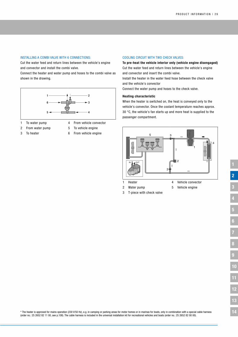
COOLing CiRCuiT WiTH TWO CHECk VALVES:
to pre-heat the vehicle interior only (vehicle engine disengaged)
Cut the water feed and return lines between the vehicle's engine
and convector and insert the combi valve.
install the heater in the water feed hose between the check valve
and the vehicle's convector
Connect the water pump and hoses to the check valve.
heating characteristic
When the heater is switched on, the heat is conveyed only to the
vehicle's convector. Once the coolant temperature reaches approx.
30 °C, the vehicle's fan starts up and more heat is supplied to the
passenger compartment.
1 Heater
2 Water pump
3 T-piece with check valve
4 Vehicle convector
5 Vehicle engine
inSTALLing A COMbi VALVE WiTH 6 COnnECTiOnS:
Cut the water feed and return lines between the vehicle's engine
and convector and install the combi valve.
Connect the heater and water pump and hoses to the combi valve as
shown in the drawing.
1 To water pump
2 From water pump
3 To heater
4 From vehicle convector
5 To vehicle engine
6 From vehicle engine
* The heater is approved for mains operation (230 V/50 Hz), e.g. in camping or parking areas for motor homes or in marinas for boats, only in combination with a special cable harness (order no.: 25 2652 82 11 00, see p.108). The cable harness is included in the universal installation kit for recreational vehicles and boats (order no.: 25 2652 82 00 00).
45
36
1 2

1
2
3
4
5
6
7
8
9
10
11
12
13
14
3 0 | P R O D u C T i n F O R M A T i O n
2 | OPTiOnAL WATER CiRCuiTS On A HyDROniC S2 ECOnOMy ExAMPLE
1. Heater2. Water pump
3. Combi valve (5 connections)4. T-piece
5. Convector6. Vehicle engine
2. WATER CiRCuiT WiTH THERMAL COMbi VALVE:
Large engines > 2.5 l and / or large cabins
Small and compact cars, short distances
Advantage: Switchover at 67 °C, variable cost-effective
installation as combi valve with five or six connections
Partial through-flow of engine from 67 °C
Prioritizes cabin heat
inSTALLing A COMbi VALVE WiTH FiVE COnnECTiOnS:
Cut through the vehicle's water feed hose from the engine to the
convector and insert the combi valve. Cut through the water return
hose from the vehicle's convector and engine and insert the T-piece.
Connect the heater and water pump and hoses to the combi valve
and T-piece as shown in the drawing.
inSTALLing A COMbi VALVE WiTH 6 COnnECTiOnS:
Cut through the water feed and return hoses between the vehicle's
engine and convector and insert the combi valve. Connect the heater
and water pump and hoses to the combi valve as shown in the
drawing.
HEATing CHARACTERiSTiC in PRE-HEATing MODE – SMALL
COOLing CiRCuiT:
until the coolant temperature reaches around 67 °C, the heater
initially conveys heat to the vehicle's own convector only, so that
the vehicle interior heats up quickly.
Once the coolant temperature reaches around 67 °C, some of the
heat from the heater is also conveyed to the engine. This allows the
engine to be pre-heated while preventing the small cooling circuit
for interior heating from cooling too fast.
HEATing CHARACTERiSTiC in ADDiTiOnAL HEATing MODE – LARgE
COOLing WATER CiRCuiT:
When the engine is running, the heat from the vehicle's convector
and engine are distributed equally, speeding up the warmup phase
and the heating of the vehicle interior.
from vehicle engine to heater
to vehicle engine
from vehicle engine Convector
Combi valve (6 connections) water pump

1
2
3
4
5
6
7
8
9
10
11
12
13
14
P R O D u C T i n F O R M A T i O n | 3 1
interior pre-heating only
RETROFiT kiTS WiTH WATER CHECk VALVE:
Retrofit kit 1 Retrofit kit 2
Order no. 24 0348 80 00 00 24 0349 80 00 00
Suitable heaters Hydronic plus universal ik Hydronic plus universal ik
ø water hose for vehicle 18 mm 20 mm
TyPE of water circuit interior heating interior heating

1
2
3
4
5
6
7
8
9
10
11
12
13
14
3 2 | P R O D u C T i n F O R M A T i O n
2 | OPTiOnAL WATER CiRCuiTS On A HyDROniC 2 COMFORT ExAMPLE
You can choose from a number of options when it comes to
installing the new Hydronic 2 Comfort. The installation can be
adapted to a wide variety of customer requirements by prioritizing
the preferred type of heating required.
1. COMFORT InSTALLATIOn: PRIORITIzATIOn OF THE InTERIOR:
This version is the most frequently used installation variant. using
the bypass, the interior and then the engine is heated (from around
67 °C).
2. SOLEnOId vALvE InSTALLATIOn FOR SPECIFIC MARKETS:
PRIORITIzATIOn OF THE EngInE
This circuit option, which heats the engine first and then the interior
(from approx. 67 °C) is available for specific markets which have a
preference for rapidly heating the engine first.
3. CLASSIC PRE-HEATER InSTALLATIOn: In-LInE WATER CIRCuIT:
Like any other pre-heater, the Hydronic 2 Comfort can of course
also be installed in-line in the water circuit. An additional dummy
plug is required to do this. ideal for installation jobs that need to be
performed at short notice.
1. Engine2. Convector3. Hydronic 2 Comfort4. Check valve
1. Comfort installation: prioritization of the interior
2
3
4
1
3. Classic pre-heater installation: in-line water circuit
2
31
2. Solenoid valve installation for specific markets: prioritization of the engine
2
3
4
1

1
2
3
4
5
6
7
8
9
10
11
12
13
14
P R O D u C T i n F O R M A T i O n | 3 3
2 | HyDROniC 2 OPTiOnAL ADD-OnS – FuEL SuPPLy
DiESEL:
Hydronic 2 Economy with pressure-resistant metering pump:
Advantage: easy to connect to the vehicle's fuel system, speeding
up installation
Prerequisite: Fuel pressure < 2 bar for diesel, no common
rail diesel (due to fuel temperature), no check valve on tank
connection, return line ends just above tank floor
Please note! The following versions of the Hydronic 2 Economy
include the pressure-resistant metering pump:
D4S 12 V: 25 2558 05 00 00
D5S 12 V: 25 2557 05 00 00
gASOLinE:
gasoline applications with a pressure of > 0.2 bar also require
the pressure reducer
Please note! For fuel lines pressurized at 2.0 bar to max. 4.0 bar,
use the pressure reducer (order no. 22 1000 20 08 00) or a separate
tank connection.
1. Fuel return line from vehicle tank cover
2. Fuel supply line from vehicle tank cover
3. Metering pump (pressure resistant up to 2.0 bar) identified with a green label
4. T-piece
5. Fuel filter – only required for contaminated fuel
6. Fuel hose, 4 x 1 (di = 2 mm, blue)
7. Fuel hose, 4 x 1.25 (di = 1.5 mm, transparent)
8. Fuel hose, 3.5 x 3 (di = 3.5 mm)
9. Elbow, 105°
10. From the vehicle tank to the engine
Permissible line lengths: Suction side: a = max. 2 mPressure side: b = max. 6 m
Fuel is extracted via a T-piece in the fuel return pipe from the
engine to the tank cover

3 4 | P R O D u C T i n F O R M A T i O n
1
2
3
4
5
6
7
8
9
10
11
12
13
14
3 | AiRTROniC: TECHnOLOgy
AiRTROniC FunCTiOnS:
Combustion air is conveyed to the combustion chamber by the fan motor and impeller.
Fuel is drawn from the vehicle's tank.
Fuel is conveyed to the combustion chamber by the metering pump.
The glow element (filament glow plug from 5 kW) vaporizes this fuel as it enters the combustion chamber and creates a combustible
fuel-air mix with the combustion air.
The resulting flame formation switches off the glow element (or filament glow plug), transfers the heat to the heating air via the convector,
and diverts exhaust gas via the exhaust silencer.
The fan motor and heating-air impeller convey cool air to the heater, where it is warmed by the convector and then blown into the vehicle
interior.
Flame monitoring and overheating sensor
Airinlet
Airoutlet
Fuel supply
Fuel-metering pump
Exhaustoutlet
Combustion-air inlet
Combustion chamber
Convector
Ceramic glow plug
Combustion-air fan
Control module
Heating-airimpeller

P R O D u C T i n F O R M A T i O n | 3 5
1
2
3
4
5
6
7
8
9
10
11
12
13
14
EbERSPäCHER AiRTROniC
Heater Airtronic D2 Airtronic D2 Airtronic D3 Airtronic b4
Product package Heater OR complete package Heater OR complete package Heater Heater
Techn. designation Airtronic (D2) Airtronic (D2) Airtronic M (D3) Airtronic M (b4)
Order no. for heater 25 2069 05 00 00 25 2070 05 00 00 25 2317 05 00 00 20 1812 05 00 00
Order no. for complete package 25 2675 05 00 00 25 2676 05 00 00 – – Fuel Diesel Diesel Diesel gasoline
Voltage V 12 24 12 12
Heating medium Air Air Air Air
Control / heat settings off / low / medium / high / power off / low / medium / high / power off / low / medium / high / power off / low / medium / high / power
Heat output W – / 850 / 1,200 / 1,800 / 2,200 – / 850 / 1,200 / 1,800 / 2,200 – / 900 / 1,600 / 2,200 / 3,000 – / 1,300 / 2,100 / 3,200 / 3,800
Fuel consumption l / h – / 0.1 / 0.15 / 0.23 / 0.28 – / 0.1 / 0.15 / 0.23 / 0.28 – / 0.11 / 0.2 / 0.28 / 0.38 – / 0.18 / 0.29 / 0.46 / 0.54
Elec. power consumption, operation W 5 / 8 / 12 / 22 / 34 5 / 8 / 12 / 22 / 34 5 / 7 / 10 / 16 / 24 5 / 9 / 15 / 29 / 40
Elec. power consumption, start W 100 100 100 100
Air flow volume w/o backpressure kg / h 13 / 40 / 60 / 90 / 105 13 / 40 / 60 / 90 / 105 24 / 60 / 90 / 120 / 150 24 / 85 / 120 / 160 / 185
Lower voltage limit V 10.2 21 10.5 10.5
upper voltage limit V 16 32 16 16
interference suppressionDisturbance class 5
(Din En 55025)Disturbance class 5
(Din En 55025)Disturbance class 5
(Din En 55025)Disturbance class 5
(Din En 55025)
Dimensions L x W x H mm 310 x 115 x 122 310 x 115 x 122 376 x 140 x 150 376 x 140 x 150
Weight empty kg 2.7 2.7 4.5 4.5
Ventilation mode available available available available
EbERSPäCHER AiRTROniC
Heater Airtronic D4 Airtronic D4 Airtronic D4 Plus Airtronic D4 Plus
Product package Heater Heater Heater Heater
Techn. designation Airtronic M (D4) Airtronic M (D4) Airtronic M (D4 Plus) Airtronic M (D4 Plus)
Order no. for heater 25 2113 05 00 00 25 2114 05 00 00 25 2484 05 00 00 25 2498 05 00 00
Fuel Diesel Diesel Diesel Diesel
Voltage V 12 24 12 24
Heating medium Air Air Air Air
Control / heat settings off / low / medium / high / power off / low / medium / high / power off / low / medium / high / power off / low / medium / high / power
Heat output W – / 900 / 2,000 / 3,000 / 4,000 – / 900 / 2,000 / 3,000 / 4,000 – / 900 / 2,000 / 3,000 / 4,000 – / 900 / 2,000 / 3,000 / 4,000
Fuel consumption l / h – / 0.11 / 0.25 / 0.38 / 0.51 – / 0.11 / 0.25 / 0.38 / 0.51 – / 0.11 / 0.25 / 0.38 / 0.51 – / 0.11 / 0.25 / 0.38 / 0.51
Elec. power consumption, operation W 5 / 7 / 13 / 24 / 40 5 / 7 / 13 / 24 / 40 5 / 7 / 16 / 30 / 55 5 / 7 / 16 / 30 / 55
Elec. power consumption, start W 100 100 100 100
Air flow volume w/o backpressure kg / h 24 / 60 / 110 / 150 / 185 24 / 60 / 110 / 150 / 185 22 / 55 / 100 / 140 / 175 22 / 55 / 100 / 140 / 175
Lower voltage limit V 10.5 21 10.5 21
upper voltage limit V 16 32 16 32
interference suppressionDisturbance class 5
(Din En 55025)Disturbance class 5
(Din En 55025)Disturbance class 5
(Din En 55025)Disturbance class 5
(Din En 55025)
Dimensions L x W x H mm 376 x 140 x 150 376 x 140 x 150 376 x 140 x 150 376 x 140 x 150
Weight empty kg 4.5 4.5 4.5 4.5
Ventilation mode available available available available

3 6 | P R O D u C T i n F O R M A T i O n
1
2
3
4
5
6
7
8
9
10
11
12
13
14
EbERSPäCHER AiRTROniC
Heater D8 LC D8 LC
Product package Heater Heater
Techn. designation 8 L (D8 LC) 8 L (D8 LC)
Order no. for heater 25 1890 00 00 00 25 1891 00 00 00
Fuel Diesel Diesel
Voltage V 12 24
Heating medium Air Air
Control / heat settings low / high low / high
Heat output W 3,500 / 8,000 3,500 / 8,000
Fuel consumption l / h 0.4 / 1.05 0.4 / 1.05
Elec. power consumption, operation W 115 115
Elec. power consumption, start W 330 380
Air flow volume w/o backpressure kg / h 310 310
Lower voltage limit V 10 20
upper voltage limit V 14 28
interference suppression Long-distance (additional measures possible) Long-distance (additional measures possible)
Dimensions L x W x H mm 653 x 260 x 250 653 x 260 x 250
Weight empty kg 14 14
Ventilation mode available available
EbERSPäCHER AiRTROniC
Heater Airtronic b5 Airtronic D5 Airtronic D5
Product package Heater Heater Heater
Techn. designation Airtronic L (b5) Airtronic L (D5) Airtronic L (D5)
Order no. for heater 20 1859 05 00 00 25 2361 05 00 00 25 2362 05 00 00
Fuel gasoline Diesel Diesel
Voltage V 12 12 24
Heating medium Air Air Air
Control / heat settings low / medium / high / power low / medium / high / power low / medium / high / power
Heat output W 2,000 / 2,700 / 4,800 / 5,500 1,600 / 2,700 / 4,800 / 5,500 1,600 / 2,700 / 4,800 / 5,500
Fuel consumption l / h 0.27 / 0.37 / 0.65 / 0.75 0.2 / 0.34 / 0.58 / 0.66 0.2 / 0.34 / 0.58 / 0.66
Elec. power consumption, operation W 15 / 30 / 80 / 85 25 / 35 / 80 / 85 25 / 35 / 80 / 85
Elec. power consumption, start W 250 250 250
Air flow volume w/o backpressure kg / h 125 / 180 / 275 / 280 155 / 190 / 275 / 280 155 / 190 / 275 / 280
Lower voltage limit V 10.5 10.5 21
upper voltage limit V 16 16 32
interference suppression Disturbance class 5 (Din En 55025) Disturbance class 5 (Din En 55025) Disturbance class 5 (Din En 55025)
Dimensions L x W x H mm 530 x 170 x 185 530 x 170 x 185 530 x 170 x 185
Weight empty kg 9.3 9.3 9.3
Ventilation mode available available available

P R O D u C T i n F O R M A T i O n | 3 7
1
2
3
4
5
6
7
8
9
10
11
12
13
14
3 | SELECTing THE AiR HEATER
The heating output information provided refers to heating the interior of a cold vehicle to around 20 °C in cold outside temperatures. if the heater
only needs to maintain the existing temperature of the interior, less heating power is required. The heating outputs are only guide values. The
exact heating requirement also depends on other environmental conditions (e.g. wind, materials, cabin walls, heating-air ducting, etc.).
guiDE VALuES FOR REquiRED HEATing OuTPuT Outside temperature
Example Volume of interior < -15 °C -15 °C to 0 °C > 0 °C
Truck cabin < 8 m3 4 kW 3 kW (2 kW)* 2 kW
Small bus 8 – 12 m3 5 kW (4 kW)* 4 kW (3 kW)* 2 kW
Motor home / van 12 – 20 m3 8 kW 6 kW (5 kW)* 4 kW
yacht / boat > 20 m3 see documentation: Marine catalog
* Values (referring to heat-insulated cabins / vehicles)
RAngE OF DEViCES AnD THEiR RESPECTiVE ADVAnTAgES:
Airtronic d2: the smallest air heater on the market, advantageous
in cramped installation spaces.
Airtronic d4: output 4,000 W, air ducting 90 mm, for vans and
suitably sized trucks; offers the advantage of high power within
a reasonable installation space, wide range of applications, from
900 W (gasoline 1,300 W) to 4,000 W.
Airtronic d3: in well insulated vehicles, 3,000 W, 90 mm air duct-
ing, energy-saving benefits of 7 – 24 W which makes it quiet and
fuel-efficient, wide-ranging application 900 – 3,000 W.
Airtronic d4 Plus: generally for longer air ducting, with the
advantage of a higher air flow volume with 90 and / or 75 mm
ducting.
tank
D2
D4
ø 60
ø 75
ø 25 mm ø 24 mm
ø 90 mm
ø 75 mm
ø 75 mm
ø 60 mm

3 8 | P R O D u C T i n F O R M A T i O n
1
2
3
4
5
6
7
8
9
10
11
12
13
14
3 | SELECTing THE AiR HEATER
ø 75 mm
check: scope of heating-air ducting(length, number of curved sections, vents, etc.)
What guide number** is required?
gUiDe nUmber≤ 3 ≤ 10
airtronic D4+
Universal iK (ø 75)
airtronic D4 Plus+
Universal iK (ø 75)
alternative***: airtronic D3
heating power requirement 4,000 W
space requirement check airtronic D4
OK
space requirement check for heating-air ductingselect ø 90 mm or 75 mm air duct
ø 90 mm
check: scope of heating-air ducting(length, number of curved sections, vents, etc.)
What guide number** is required?
gUiDe nUmber≤ 15 ≤ 10
airtronic D4 Plus+
Universal iK (ø 90)
airtronic D4+
Universal iK (ø 90)
alternative***: airtronic D3

P R O D u C T i n F O R M A T i O n | 3 9
1
2
3
4
5
6
7
8
9
10
11
12
13
14
* installation kit plus = expanded product package
** guide number: each component of the heating-air ducting (air hose, curved sections, vents, etc.) has a line guide number. the sum of these line guide numbers must not be greater than the guide number for the
heater, otherwise the heater could malfunction – e.g. overheating the higher the guide number for the heater, the more heating-air ducting components may be connected. please refer to Eberspächer's acces-
sories catalog for a detailed explanation of guide numbers.
*** airtronic D3 option: lower heating power (3,000 W) and therefore lower power consumption + and quieter operation => e.g. for well-insulated cabins
ø 60 mm
check: scope of heating-air ducting(length, number of curved sections, vents, etc.)
What guide number** is required?
gUiDe nUmber
airtronic D2+
Universal iK (ø 60)or
airtronic D2 complete package
≤ 6
heating power requirement 2,000 W
space requirement check airtronic D4
OK
space requirement check for heating-air ductingselect ø 75 mm or 60 mm air duct
ø 75 mm
check: scope of heating-air ducting(length, number of curved sections, vents, etc.)
What guide number** is required?
gUiDe nUmber
≤ 12
airtronic D2+
installation kit Plus* (ø 75)

4 0 | P R O D u C T i n F O R M A T i O n
1
2
3
4
5
6
7
8
9
10
11
12
13
14
3 | inSTALLATiOn kiTS
gEnERAL nOTES On HEATing-AiR DuCTing: Heating-air ducting can also be mounted onto the heater. Each
part has a line guide number which indicates the reduction in
the heating-air throughput. in order to give you the opportunity
to check that the installation you have planned does not reduce
the heating-air throughput to an inadmissible level, we have
calculated a heater guide number for each heater and a line
guide number for each heating-air ducting; see information in
the guide number tables:
0 = no temperature increase,
− = no line guide number.
The total of the line guide numbers of the heating-air ducts
connected to the heater must not be greater than the heater
guide number, as otherwise the vent temperature would be
inadmissibly high, the heat distribution would be uneven and
the overheating sensor would respond. if the total of the line
guide numbers is greater than the heater guide number, the
total can be reduced by selecting a larger diameter for the air
ducts or switching from a one-duct to a two-duct system.
1-duct means:
One heating-air duct leads to or from the heater. The line guide
numbers under “1-duct” apply.
2-duct means:
After the heater, the heating-air line divides into two ducts. up
until this branch, the line guide numbers specified under “1-
duct” apply, from the branch onwards the line guide numbers
under “2-duct” apply. note the information on air ducting
and calculating the total of the guide line numbers starting on
page 42.
When using two air ducts or multiple vents, at least one of the
ducts must be permanently open.
The branch that can be closed must not be taken into account
when calculating the total of the line guide numbers.
RuLE OF THuMb:
Double cross-section or two lines the same, routed in parallel =
1 / 4 of the guide number.
Example:
Hose ø 60 mm
Cross-section A = 19.6 cm2, guide number 1.0
Hose ø 75,
Cross-section A = 44.2 cm2, guide number 0.25
With smooth welded pipes, the line guide number is only half of the
flexible hose with the same diameter (i.e. double pipe length).
2-duct1-duct
WiTH innOVATiVE AiR COnTROL uniTS:To counter the uneven distribution of warm air in systems with
multiple ducts and vents, we have developed innovative air flow
regulating elements that are simply clipped into the hose connection
fitting of the air vent. These patented regulating elements reduce
the air flow cross-section accordingly and therefore the amount of
air that escapes. Available for fitting diameters 60, 75 and 90 mm.

P R O D u C T i n F O R M A T i O n | 4 1
1
2
3
4
5
6
7
8
9
10
11
12
13
14
Airtronic: Heater guide no = 6
ExAMPLE CALCuLATiOn FOR HEATing-AiR DuCTing:
7
nO. DESCRiPTiOn LinE guiDE nuMbER1 Protective grille 1.7
2 Connectors ø 60 1.7
3 Flex. Pipe ø 60, 0.3 m long 0.3
4 Flex. Pipe ø 60, 1.0 m long 1.0
5 Straight air scoop, ø 60 0
6 1 x 90° elbow, flex. pipe 0.6
7 Rotating air vent 1.4
total of the line guide numbers 5.0
Total of line guide numbers, 5.0, does not exceed the heater guide number 6,
so the installation is admissible.
HEATER guiDE nuMbERS:
HEATER guiDE nuMbERAirtronic D2 with scoop 60 6
Airtronic D2 with scoop 75 12
Airtronic D3 / D4 / b4 with scoop 75 3
Airtronic D3 / D4 / b4 with scoop 90 10
Airtronic D4 Plus with scoop 75(air-recirculation mode)
8
Airtronic D4 Plus with scoop 75(in fresh-air mode)
10
Airtronic D4 Plus with scoop 90 15
THE nEW RAngE OF AiR VEnTS:Particularly colorfast and durable even at high temperatures, the
covers of our completely re-designed range of vents are impressive,
featuring a streamlined and high-quality design that allows for a
variety of flow directions. They are available in white and black,
allowing seamless integration into any interior.
Clear, simple system thanks to the modular design.
Plug-in connections between cover and fitting or fitting and air
hose for easy assembly.
Fittings available in 50, 60, 75 and 90 mm.
4 2 | P R O D u C T i n F O R M A T i O n
1
2
3
4
5
6
7
8
9
10
11
12
13
14
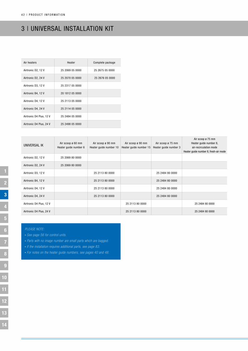
Air heaters Heater Complete package
Airtronic D2, 12 V 25 2069 05 0000 25 2675 05 0000
Airtronic D2, 24 V 25 2070 05 0000 25 2676 05 0000
Airtronic D3, 12 V 25 2317 05 0000
Airtronic b4, 12 V 20 1812 05 0000
Airtronic D4, 12 V 25 2113 05 0000
Airtronic D4, 24 V 25 2114 05 0000
Airtronic D4 Plus, 12 V 25 2484 05 0000
Airtronic D4 Plus, 24 V 25 2498 05 0000
uniVERSAL ikAir scoop ø 60 mm
Heater guide number 6Air scoop ø 90 mm
Heater guide number 10Air scoop ø 90 mm
Heater guide number 15Air scoop ø 75 mm
Heater guide number 3
Air scoop ø 75 mmHeater guide number 8, air-recirculation mode
Heater guide number 8, fresh-air mode
Airtronic D2, 12 V 25 2069 80 0000
Airtronic D2, 24 V 25 2069 80 0000
Airtronic D3, 12 V 25 2113 80 0000 25 2484 80 0000
Airtronic b4, 12 V 25 2113 80 0000 25 2484 80 0000
Airtronic D4, 12 V 25 2113 80 0000 25 2484 80 0000
Airtronic D4, 24 V 25 2113 80 0000 25 2484 80 0000
Airtronic D4 Plus, 12 V 25 2113 80 0000 25 2484 80 0000
Airtronic D4 Plus, 24 V 25 2113 80 0000 25 2484 80 0000
3 | uniVERSAL inSTALLATiOn kiT
plEasE notE:
• see page 56 for control units.
• parts with no image number are small parts which are bagged.
• if the installation requires additional parts, see page 83.
• for notes on the heater guide numbers, see pages 40 and 48.

P R O D u C T i n F O R M A T i O n | 4 3
1
2
3
4
5
6
7
8
9
10
11
12
13
14
heater – PRODuCT PACkAgE:
1 Airtronic heater
2 Metering pump
cOmPlete PacKage – PRODuCT PACkAgE:
1 Airtronic heater
2 Metering pump
– installation kit with ø 60 mm air scoop
3 EasyStart Select
4 Fuel tank extractor – only with complete package 25 2676 05 0000
UniVersal installatiOn Kit – PRODuCT PACkAgE:
5 Cable harness, pos / neg (included with item 22)
6 Cable harness, operation (included with item 22)
7 Flexible exhaust pipe (1 m long)
8 Combustion-air hose (1 m long)
9 Cable tie (2x 10)
10 Mounting bracket, metering pump
11 Pipe, 6 x 2 (1.5 m long)
12 Pipe, 4 x 1.25 (7.5 m long)
13 Hose clip (1x)
14 Vent, 30° (ø 75 / 90 mm)
15 Fitting (ø 75 mm)
16 Flat vent, 30° (ø 50 / 60 mm)
17 Fitting (ø 60 mm)
18 grille
19 Scoop
20 Flexible pipe
21 Exhaust silencer
22 Cable harness, heater
* Only with the complete Airtronic D2 package.* Only with the complete 24 V Airtronic D2 package. *** Only with the Airtronic D2 installation kit and the complete Airtronic D2 package.**** Only with the installation kit for the Airtronic b3 Plus, D3, b4, D4 and D4 Plus.

4 4 | P R O D u C T i n F O R M A T i O n
1
2
3
4
5
6
7
8
9
10
11
12
13
14
inSTALLATiOn kiT
“PLuS”Air scoop ø 75 mm
Heater guide number 12
Airtronic D2, 12 V 25 2069 82 0000
Airtronic D2, 24 V 25 2069 82 0000
3 | “PLuS” inSTALLATiOn kiTS
plEasE notE:
• see page 56 for control units.
• parts with no image number are small parts which are bagged.
• if the installation requires additional parts, see page 83.
• for notes on the heater guide numbers, see pages 40 and 48.
“PLuS” inSTALLATiOn kiTS ARE iDEAL FOR inSTALLATiOnS in MOTOR HOMES AnD bOATS.

P R O D u C T i n F O R M A T i O n | 4 5
1
2
3
4
5
6
7
8
9
10
11
12
13
14
heater – PRODuCT PACkAgE:
1 Airtronic heater
2 Metering pump
installatiOn Kit “PlUs” – PRODuCT PACkAgE:
3 Combustion-air intake silencer
4 Exhaust silencer
5 Fitting (3x ø 60 mm)
6 Flat vent, 0° (ø 50 / 60 mm)
7 y-junction (ø 75 / 60 / 60 mm)
8 Tank connection kit
9 Temperature control sensor
10 Cable harness for temperature control sensor
12 Cable harness, pos / neg (included with item 17)
13 Cable harness, operation (included with item 17)
14 Hose clip (2x ø 60 mm)
15 Hose clip (2x ø 75 mm)
16 Pipe 4 x 1.25 (6 m long; included with item 8)
17 Cable harness, heater
18 Flexible exhaust pipe (1 m long)
19 grille
20 Holder, metering pump
21 Cable tie (2 sets)
22 Air scoop (ø 75 mm)
23 Flat vent, 30° (2x ø 50 / 60 mm)
24 Adapter ø 6 / 4
25 Pipe 4 x 1 (6 m long; included with item 8)
26 Pipe clip ø 50 mm
nOt in PrODUct PacKage:
11 Flexible pipe (ø 75 mm) for heating-air ducting
27 Flexible pipe (ø 60 mm) for heating-air ducting
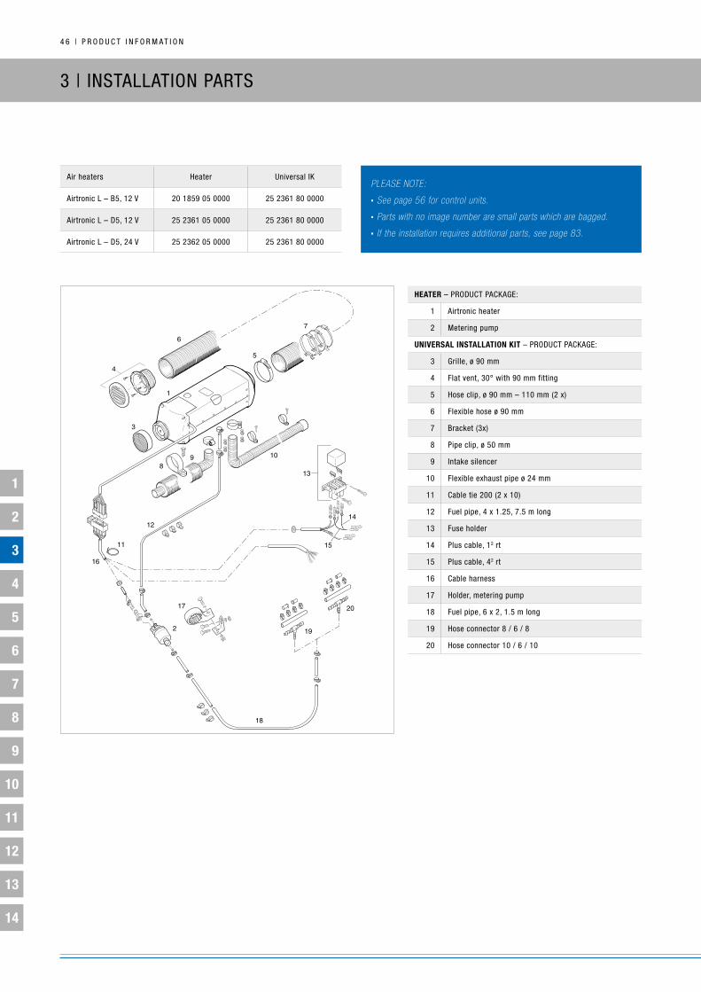
4 6 | P R O D u C T i n F O R M A T i O n
1
2
3
4
5
6
7
8
9
10
11
12
13
14
Air heaters Heater universal ik
Airtronic L – b5, 12 V 20 1859 05 0000 25 2361 80 0000
Airtronic L – D5, 12 V 25 2361 05 0000 25 2361 80 0000
Airtronic L – D5, 24 V 25 2362 05 0000 25 2361 80 0000
3 | inSTALLATiOn PARTS
heater – PRODuCT PACkAgE:
1 Airtronic heater
2 Metering pump
UniVersal installatiOn Kit – PRODuCT PACkAgE:
3 grille, ø 90 mm
4 Flat vent, 30° with 90 mm fitting
5 Hose clip, ø 90 mm – 110 mm (2 x)
6 Flexible hose ø 90 mm
7 bracket (3x)
8 Pipe clip, ø 50 mm
9 intake silencer
10 Flexible exhaust pipe ø 24 mm
11 Cable tie 200 (2 x 10)
12 Fuel pipe, 4 x 1.25, 7.5 m long
13 Fuse holder
14 Plus cable, 12 rt
15 Plus cable, 42 rt
16 Cable harness
17 Holder, metering pump
18 Fuel pipe, 6 x 2, 1.5 m long
19 Hose connector 8 / 6 / 8
20 Hose connector 10 / 6 / 10
plEasE notE:
• see page 56 for control units.
• parts with no image number are small parts which are bagged.
• if the installation requires additional parts, see page 83.

P R O D u C T i n F O R M A T i O n | 4 7
1
2
3
4
5
6
7
8
9
10
11
12
13
14
Air heaters Heater
D8 LC, 12 V 25 1890 00 0000
D8 LC, 24 V 25 1891 00 0000
heater – PRODuCT PACkAgE:
1 Heater, pre-mounted
2Metering pump with integrated fuel filter and mounting bracket
3 Control unit
4 Temperature sensor, external
5 Cable harness with connection parts
6 bushing connector housing with connection parts
7 blade fuse with fuse holder
8bushing connector housing with busing connectors and seals (2 x)
9 Rubber-metal buffer with fastening parts (4 x)
nOt inclUDeD in PrODUct PacKage:
10 Cable harness, temperature sensor 25 1482 89 4000
11 Combustion air hose 10 2114 25 0000
11a Hose clip 10 2067 03 2050
11b End sleeve for combustion-air hose 25 1480 89 0400
12 Pipe clip for flex. exhaust pipe LW42 152 05 005
13 Flexible exhaust pipe LW42 360 61 381
14End sleeve for flex. exhaust pipe LW42
22 1000 40 0200
– Exhaust pipe (rigid) 047 05 044
15* Cable harness, control unit
plEasE notE:
• see page 56 for control units.
• parts with no image number are small parts which are bagged.
• if the installation requires additional parts, see page 83.
* Self-assembly with the 5 m cable harness (Order no. 22 1000 30 0300). Cut the existing connectors off the cable harness. Prepare the cable strands for the bushing connectors and fit them. The bushing connectors are included in the product package. Connect the cable harness to the cable harness connector (5) and to the bushing connector housing of the control unit (6) following the circuit diagrams at the end of the documentation.

4 8 | P R O D u C T i n F O R M A T i O n
1
2
3
4
5
6
7
8
9
10
11
12
13
14
AiRTROniC
Heater number 6 – with ø 60 air scoop
Heater number 12 – with ø 75 air scoop
The drawing shows the application options for the main air ducts.
There are no installation examples.
0°
0°
0°0°
0°
24
24
24
24 2430
24
24
24
24
26
37 3839
26
28
28
29
29
19
25
25
30°
30°
30°
30°
90°
90°
0°
30°
30°90°
90°
30° 30°
= ø 50 mm
= ø 60 mm
= ø 75 mm
PLEASE nOTE:
For an explanation of one- and two-duct heating-air ducting, see
page 40.
3 | guiDE nuMbERS

P R O D u C T i n F O R M A T i O n | 4 9
1
2
3
4
5
6
7
8
9
10
11
12
13
14
nO. nAME (DiMEnSiOnS in MM)LinE guiDE nuMbER
1-DuCTLinE guiDE nuMbER
2-DuCT
SEE SERiES nO. SEC. 7AiR-COnDuCTing
PARTSheating-air duct with ø 60 scoop (heater guide number 6)
1 Scoop, ø 60 0 0 21
2 Flex. pipe ø 60 per m 1.0 0.25 1
3 90° elbow, flexible pipe 0.6 – –
4 Flat vent, 0° with ø 60 fitting 0.5 0.1 13
5 Fitting, ø 60 0 0 16
6 Heater grille, ø 60 0 – 17
7 Air filter, ø 60 1.6 – 5
8 ball-shaped scoop, ø 60 4.8 – 32
9 ø 50 connection fitting for ø 60 ø 75 ball-shaped scoops 4.5 – 31
10 Pipe elbow, 90° ø 60 4 – 33
11 upright vent, 30° with ø 60 fitting 3.2 0.8 10
12 T-junction 1.4 0.25 35
13 butterfly valve ø 60 / 60 / 60 with “right / left“ flap position – 0.6 40
14 y-junction – 1 43
15 Closable vent ø 50 / 60 – – 12
16 Flat vent, 30° ø 50 / 60 0.7 0.2 11
17 Symmetrical metal y-junction ø 60 / 50 / 50 – 0.3 42
18 upright vent, 90° ø 50 / 60 n / a n / a 14
heating-air duct with ø 75 scoop (heater guide number 12)
19 Adapter
20 Scoop, ø 75 0 0 21
21 Flex. pipe ø 75 per m 1 0.25 1
22 90° elbow, flex. pipe, ø 75 0.2 – 1
23 intake silencer, ø 75 0.7 – 4
24 Fitting, ø 75 0 0 20
25 Flat vent, 0° ø 75 / 90 with ø 75 fitting 0.6 0.1 13
26 upright vent, 30° ø 75 / 90 with ø 75 fitting 0.5 0.15 10
27 Pipe elbow, 90° ø 75 4.5 – 33
28 Flat vent, 30° with ø 75 fitting 0.5 0.15 11
29 upright vent, 90° with ø 75 fitting 0.8 0.15 14
30 Closable vent ø 75 / 90 with ø 75 fitting 0.6 0.2 11
31 T-junction ø 75 / 75 / 75 – 0.8 35
32butterfly valve, ø 75 / 75 / 75 Flap position “left / right”Flap position “center”
– 1.2 40
33 y-junction ø 75 / 75 / 75 – 0.6 43
34 Hose connector fitting, ø 75 0.5 0.1 44
35 Silencer, ø 75 0.6 – 3
36 ball-shaped scoop, ø 75 6 – 32
37 Symmetrical plastic y-junction ø 75 / 60 / 60 – 0.8 42
38 Symmetrical metal y-junction ø 75 / 50 / 50 – 0.9 42.1
39 Adapter ø 75 – 60 3.2 – 45

5 0 | P R O D u C T i n F O R M A T i O n
1
2
3
4
5
6
7
8
9
10
11
12
13
14
0°
0°
0°
0°
0°
0°
0°
30°
30°
30°
90°
90°
90°
90°
90°
30°
30°
30°
30°
30°
17
17
17
21
21
21
21
21
21
21
21 21
4143
44
42
19
23
23
37
37
38
38
39
39 35
17
13
13
45
13
12
1233
29
15
15
1718
30°
30°
= ø 50 mm
= ø 75 mm
= ø 90 mm
= ø 100 mm
PLEASE nOTE:
For an explanation of one- and two-duct heating-air ducting,
see page 40.
AiRTROniC M
Heater number 3 – with ø 75 air scoop
Heater number 10 – with ø 90 air scoop
The drawing shows the application options for the main air ducts.
There are no installation examples.
* Heater guide numbers for the Airtronic D4 Plus are different, see
page 42.
3 | guiDE nuMbERS

P R O D u C T i n F O R M A T i O n | 5 1
1
2
3
4
5
6
7
8
9
10
11
12
13
14
nO. nAME (DiMEnSiOnS in MM)LinE guiDE nuMbER
1-DuCTLinE guiDE nuMbER
2-DuCTSEE SERiES nO. SEC. 7
AiR-COnDuCTing PARTSø 75 ø 90 ø 75 ø 90
heating-air duct with a ø 75 scoop (heater guide number 3)
1a Scoop, ø 75 0 – – – 21
2 Flex. pipe ø 75 per m 1 – 0.25 – 1
3 90° elbow, flexible pipe, ø 75 0.2 – – – 1
4 Flat vent, 0° with ø 75 fitting 0.4 – 0.1 – 13
5 Fitting, ø 75 0.0 – 0.0 – 16
6 grille, ø 75 2.0 – – – 17
7 intake silencer, ø 75 0.8 – – – 4
8 T-junction, ø 75 – – 0.5 – 35
9 butterfly valve ø 90 / 90 / 90 with 75 / 90 adapters – – 1.8 – 40
10 Plastic y-junction ø 75 / 75 / 75 – – 0.6 – 43
11 Flat vent, 30° with ø 75 fitting 0.4 – 0.1 – 11
12 upright vent, 30° with ø 75 fitting 0.6 – 0.2 – 10
13 upright vent, 90° with ø 75 fitting 1.1 – 0.3 – 14
14 ball-shaped scoop, ø 75 2.0 – – – 32
15 Closable vent with ø 75 fitting – – – – 12
16 Ring, ø 75 / 90 0.5 – – – 34
17 Symmetrical plastic y-junction ø 75 / 60 / 60 – – 0.9 – 42
18 Hose connector 0.5 – 0.1 – 44
heating-air duct with ø 90 scoop (heater guide number 10)
1b Scoop, ø 90 – 0 – – 21
18 Flex. pipe ø 90 per m – 1 – 0.25 1
19 Hose connector fitting, ø 90 – 0.5 – 0.1 44
20 Silencer, ø 90 – 0.7 – – 3
21 Fitting, ø 90 – 0 – 0 16
23 Flat vent, 0° with ø 90 fitting – 1.1 – 0.3 13
24 butterfly valve, ø 90 / 90 / 90 – 1.2 – – 40
25 y-junction ø 90 / 90 / 90 – – – 0.3 43
26 ball-shaped scoop, ø 90* – 5.0 – – 32
27 Ring, ø 90 / 100 – 0 – – 34
28 Flexible pipe, ø 100, per m – 0.4 – – 1
29 Hose connector fitting, ø 100 – 0.1 – – 44
30 Silencer, ø 100 – 0.5 – – 3
31 Rotatable vent ø 100 – 2.1 – 0.5 11.1
32 y-junction ø 100 / 100 / 100 – – – 0.5 43
33 Adapter ø 75 – 100 – – – 0.8 45
34a Connection fitting 50x ø 75 – – – 1.0 31
34b Connection fitting 50x ø 90 – – – 2.5 31
35 Closable vent with ø 90 fitting – – – – 12
36 T-junction, ø 90 – – – 0.6 35
37 Flat vent, 30° with ø 90 fitting – 2.0 – 0.4 11
38 upright vent, 90° with ø 90 fitting – 2.7 – 0.3 14
39 upright vent, 30° with ø 90 fitting – 2.4 – 0.6 10
40 90° elbow, flexible pipe, ø 90 0.1 – – – 1
41 Symmetrical plastic y-junction ø 90 / 75 / 75 – – – 0.9 42
42 Symmetrical plastic y-junction ø 90 / 60 / 60 – – – 2.1 42
43 Adapter ø 75 – 90 – 3.3 – – 45
44 T-junction, ø 100 – – – 0.4 35
45 Adapter ø 90 – 100 – 0.4 – – 45
* Cannot be used with the Airtronic D4 Plus

5 2 | P R O D u C T i n F O R M A T i O n
1
2
3
4
5
6
7
8
9
10
11
12
13
14
AiRTROniC L
Heater number 10
The drawing shows the application options for the main air ducts.
There are no installation examples.
PLEASE nOTE:
For an explanation of one- and two-duct heating-air ducting, see
page 40.
= ø 75 mm
= ø 90 mm
= ø 100 mm
0°
0°
0°
0°
30°
90°
30°
30°
30°30°
90°
23
2
23
23
23
23
23
23
23 23
23
23
28
28
29
29 26
24
24
9
12
11
33
18
0° 30°30°
90°
21
20
32
21
27
21
34
30 31
21 21
22
13
3 | guiDE nuMbERS

P R O D u C T i n F O R M A T i O n | 5 3
1
2
3
4
5
6
7
8
9
10
11
12
13
14* item 4 – when using the ø 90 / 100 adapter, cut the grille
nO. nAME (DiMEnSiOnS in MM)LinE guiDE nuMbER
1-DuCTLinE guiDE nuMbER
2-DuCT
SEE SERiES nO. SEC. 7AiR-COnDuCTing
PARTSheating-air duct with ø 90 scoop (heater guide number 10)
1 Metal grille vent ø 90 0.6 0.2 13.1
2 Hose fitting ø 90 0 0 18
3 Flexible pipe, ø 100, per m 0.6 0.2 1
3a 90° elbow, flexible pipe, ø 100 0.6 – 1
4 Adapter ø 90 / 100 0 – 45
5 Flat vent, 0° with ø 90 fitting 1 0.2 13
6 Flexible pipe, ø 90, per m 1 0.25 1
6a 90° elbow, flexible pipe, ø 90 0.2 – 1
7 intake silencer, ø 90 0.8 – 3
8 ball-shaped scoop, ø 90 8 – 22
9 Hose connector fitting, ø 90 0.5 0.1 46
10 Silencer, ø 100 0.5 – 3
11 Hose connector fitting, ø 100 0.4 0.1 44
12 Flat vent, ø 100, 30° 2 0.5 11.1
13 Symmetrical plastic y-junction ø 90 / 75 / 75 – 0.9 42
14 y-junction ø 100 / 100 / 100 – 0.5 43
15 T-junction ø 100 / 100 / 100 – 0.5 35
16 y-junction ø 90 / 90 / 90 – 0.6 43
17 butterfly valve, ø 90 / 90 / 90 – 1.1 40
18 Adapter ø 75 – 100 3.2 – 45
19 Flexible pipe, ø 75, per m 4 1 1
20 Plastic heater grille, ø 90 2 – 17
21 Fitting, ø 75 0 0 16
22 Closable vent with ø 75 fitting – – 12
23 Fitting, ø 90 0 0 16
24 upright vent, 90° with ø 90 fitting 3 0.8 14
25 T-junction ø 90 / 90 / 90 – 0.6 35
26 Closable vent with ø 90 fitting – – 12
27 Flat vent, 0° with ø 75 fitting 2.5 0.7 13
28 Flat vent, 30° with ø 90 fitting 1.7 0.4 11
29 upright vent, 30° with ø 90 fitting 2.3 0.6 10
30 Flat vent, 30° with ø 75 fitting 2.7 0.8 11
31 upright vent, 30° with ø 75 fitting 2.1 0.5 10
32 upright vent, 90° with ø 75 fitting 4.7 1.2 14
33 Scoop, ø 90 0 0 –
34 90° elbow, flexible pipe, ø 75 1 0.25 1

5 4 | P R O D u C T i n F O R M A T i O n
1
2
3
4
5
6
7
8
9
10
11
12
13
14
AiR HEATER 8 L
Heater number 8
The drawing shows the application options for the main air ducts.
There are no installation examples.
= ø 75 mm
= ø 90 mm
= ø 100 mm
0° 30°30°
90°
17
25
17
22
17
20
21
14
15
23 24
17 17
18
0°30°
30°
90°
26
30
26
27
26
28 29
26 26
19
PLEASE nOTE:
For an explanation of one- and two-duct heating-air ducting,
see page 40.
3 | guiDE nuMbERS

P R O D u C T i n F O R M A T i O n | 5 5
1
2
3
4
5
6
7
8
9
10
11
12
13
14
nO. nAME (DiMEnSiOnS in MM)LinE guiDE nuMbER
1-DuCTLinE guiDE nuMbER
2-DuCT
SEE SERiES nO.AiR-COnDuCTing
PARTSheating-air duct with ø 100 scoop (heater guide number 8)
1 grille, ø 100 0.1 – 17
2 Flexible pipe, ø 100, per m 1 0.25 1
2a 90° elbow, flexible pipe, ø 100 0.5 0.15 1
3 Metal hose fitting, ø 100 0 0 18
4 grille, ø 100 1.8 0.1 13.1
5 Silencer, ø 100 1.1 0.25 3
6 Hose connector fitting, ø 100 0.5 0.1 44
7 Rotatable vent ø 100 5.5 1.2 11.1
8 Adapter ø 90 – 100 1.4 – 45
9 butterfly valve, ø 90 / 90 / 90 – 2.6 40
10 Flexible pipe, ø 90, per m 3 0.8 1
13 y-junction, ø 100 – 0.4 43
14 Adapter ø 75 – 100 6.1 – 47
15 Flexible pipe, ø 75, per m – 2 1
17 Fitting, ø 75 0 0 16
18 Closable vent 75 – – 12
19 Closable vent 90 – – 12
20 90° elbow, flexible pipe, ø 75 – 1.1 1
21 T-junction, ø 100 – 0.2 35
22 Flat vent, 0° with ø 75 fitting – 1.3 13
23 Flat vent, 30° with ø 75 fitting – 1.5 11
24 upright vent, 30° with ø 75 fitting – 1.6 10
25 upright vent, 90° with ø 75 fitting – 1.8 14
26 Fitting, 90 0 0 16
27 Flat vent, 0° with ø 90 fitting – 0.8 13
28 Flat vent, 30° with ø 90 fitting – 1.1 11
29 upright vent, 30° with ø 90 fitting – 1.1 10
30 upright vent, 90° with ø 90 fitting – 1.3 14

5 6 | P R O D u C T i n F O R M A T i O n
1
2
3
4
5
6
7
8
9
10
11
12
13
14
3 | COnTROL uniTS
COnTROL uniTS
Modeleasystart select
Control uniteasystart timer
Timereasystart remote
Remote controleasystart remote+
Remote controleasystart Web**/***
Web-based remote control
Order number 22 1000 34 13 00 22 1000 34 15 00 22 1000 34 23 00 22 1000 34 17 00 22 1000 34 51 00
Description basic version Comfort version basic version Comfort version
Operation by smartphone app (available for iPhone and Android) or web app
(browser version)
Functions
• Heating / ventilation on / off
• Heating / ventilation on / off
• Program / delete pre-select mode
• Long-press function for immediate heating
• A second / additional heater can be operated
• Heating / ventilation on / off
• Operating time adjustable
• Heating / ventilation on / off
• Program / delete pre-select mode
• Long-press function for immediate heating
• A second / additional heater can be operated
• Heating / ventilation on / off
Programming the timer –
• Three programming loca-tions within seven days
• Selection of individual days of the week or one of three time periods (Mo.–Fr. / Sa.+Su. / Mo.–Su.)
–
• Three programming loca-tions within seven days
• Selection of individual days of the week or one of three time periods (Mo.–Fr. / Sa.+Su. / Mo.–Su.)
• Three programming loca-tions within seven days
• Selection of individual days of the week or one of three time periods (Mo.–Fr. / Sa.+Su. / Mo.–Su.)
Timer programming: automatic heating time calculation
– Optional with connection of
temperature sensor – yes yes
immediate start-up mode running time
60 min. preset Adjustable 10 – 120 min.Adjustable 10, 20, 30, 40,
50 or 60 min.Adjustable 10 – 120 min. Adjustable 10 – 720 min.
Pre-ventilation* yes yes yes yes yes
Display interior temperature
– Optional – yes yes
Feedback
• Status: Heater• Status: Connection to the
heater
• Status: Heater• Status: Connection to the
heater
• Data transfer successful• Status: Heater • Status: Connection to the
heater
• Data transfer successful• Status: Heater and timer• Status: Connection to the
heater
• Status: Heater and timer• Feedback via app or
browser version• Status: Connection to the
heater
Range – – up to 1 km under
optimum conditionsup to 1 km under
optimum conditionsunlimited (given network
coverage)
Display
LED-illuminated iCOn display.
Lighting can be integrated with vehicle lighting circuit.
Matrix display illuminated with LEDs.
Lighting can beintegrated with vehicle
lighting circuit.
Two-tone LEDMatrix display illuminated
with LEDs.
Display on smartphone app or web browser.
illuminated button in the vehicle.
* Depending on heater type** End users can pre-book connectivity at standard cellphone rates for 12 months at a time at www.myeberspaecher.com*** network coverage available in the following countries: Austria, belgium, Czech Republic, Denmark, Estonia, Finland, France, germany, great britain and northern ireland, italy, Latvia, Lithuania, netherlands, norway, Poland, Romania, Russia, Sweden, Switzerland, Turkey, ukraine and belarus.

P R O D u C T i n F O R M A T i O n | 5 7
1
2
3
4
5
6
7
8
9
10
11
12
13
14
3 | COnTROL uniTS
ACCESSORiES EasyStart Select EasyStart Timer EasyStart Remote EasyStart Remote+ EasyStart Web
Temperature sensorfor displaying interior temperature
— 22 1000 34 22 00 —included in the product
packageincluded in the product
package
Timer trim — 22 1000 51 41 00 — — —
easystart Web: This product can be combined with one of the following control units from the EasyStart family: EasyStart Select, EasyStart Timer, EasyStart Remote.
easystart timer and easystart remote+
APPROVED COMbinATiOnS OF HEATER AnD COnTROL uniT:OPTiOn 1you can control a second heater by using the DAT line (purple) and the diagnostic line (blue and white). However, it is not possible to connect an additional control unit. Diagnostics can be run for both heaters.
OPTiOn 2you can switch on any device by activating the switch output (switch on / vehicle blower output). A second control unit can be connected via the DAT line (purple). Diagnostics is available for the first heater but not for the second.
COMPATibiLiTy MODE FOR HEATERS WiTHOuT EbERSPäCHER DiAgnOSTiCS, E.g. AiR HEATER D8 LC:Heater diagnostics can be run with TP6 control units and EDiTH diagnostics (diagnosis of up to five faults). Air heaters also require a separate control unit for inputting setpoints.
SLAVE COnTROL uniTS
EasyStart Select EasyStart Timer EasyStart Remote button EasyStart Web
EasyStart Timer x x x x —
EasyStart Remote+ x x —included in the product
package—
EasyStart Web x x xincluded in the product
package—
MAS
TER
CO
nTRO
L un
iTS
APPROVED
COMbinATiOnS

5 8 | P R O D u C T i n F O R M A T i O n
1
2
3
4
5
6
7
8
9
10
11
12
13
14
3 | OPTiOnAL ADD-OnS
AiR-RECiRCuLATiOn MODE WiTH inTERnAL TEMPERATuRE
SEnSOR:
STAnDARD SETuP:
Air-recirculation mode with measurement of actual temperature by
temperature sensor in heater.
OPTiOnAL ADD-On 1:
Fresh-air mode with measurements of actual temperature using
external temperature sensor installed separately in a suitable area
for measuring the required temperature.
OPTiOnAL ADD-On 2 – PRE-VEnTiLATiOn:
Airtronic heaters come with the pre-ventilation function. both this
and the EasyStart control units are automatically detected (see
Commissioning EasyStart control units). For other heaters or control
units, see the technical information.

P R O D u C T i n F O R M A T i O n | 5 9
1
2
3
4
5
6
7
8
9
10
11
12
13
14
FRESH-AiR MODE WiTH ExTERnAL SEnSOR:
OVERViEW: FRESH-AiR MODE AnD TEMPERATuRE DiSPLAy OPTiOnS On THE EASySTART COnTROL uniTS, EasyStart Timer ExAMPLE:
0,5 GYBK
Θ
0,5 BNWH
0,5 GYRD
g
y
0,5 GY
0,5 BNWH
0,5 RD
0,5 BUWH
0,5 BNc
0,35 RD
0,22 GYBK
0,22 BN
0,22 BUWH
0,22 VT
0,35 YE
0,22 BNYE
0,22 WHRD
0,22 BNWH
0,22 GY
1
2
1
2
1
2
3
4
5
6
7
8
9
10
1
2
3
4
5
6
7
8
9
10
-B9
-XB2 -XS2
-E3
-XB10 -XS10
X:58
Light (+)
X:15
Ign (+)
E3 EasyStart Timer 22 1000 34 15 00
c to the heater
y connect and insulate lines
g to the heaterb9 temperature control sensor exterior, interior 25 1774 89 03 00 PTC resistance R25 = 2000 Ω
Temperature sensor 2.15.1 for displaying the interior temperature
Exterior temperature sensor b9 for fresh air heating modeFor connection, the technical information for the heater

6 0 | P R O D u C T i n F O R M A T i O n
1
2
3
4
5
6
7
8
9
10
11
12
13
14
4 | SERViCE: EASySCAn DiAgnOSTiC AnD SERViCE TOOL
1. ADVAnTAgES (FunCTiOnS):
Compatibility with universally applicable
automotive standards (CAn, uDS)
new, modern, user-friendly interface
Comprehensive evaluation of current operating status
Automatic creation of a usage profile
Error analysis of devices and components
Error code output for heaters with CAn communication
including additional system parameters
Heating application function check
Commissioning support for heating systems with
CAn communication
integrated results log at the end of commissioning and for
diagnostic sessions
Existing heater adapters can continue to be used
Direct link to the Eberspächer Partner Portal at any time
Set up for installing datasets, e.g. for the Fan and Flap Module
EasyFan as well as EasyStart Web updates
2. FuRTHER FEATuRES:
PC software is downloaded via the Partner Portal
Alternative for installing and updating software locally from
a data carrier
Ongoing updates provided on the Partner Portal
Product package: VCi, uSb cable and y adapter cable (connection
for existing heaters and forthcoming applications)
EASySCAn – THE nEW DiAgnOSTiC AnD SERViCE
TOOL FOR PRE-HEATER SySTEMS:
EasyScan is the diagnostic and service tool for the
decades to come – it is the workshop's future-
proof solution for challenges in the long term. The
proprietary Eberspächer standard is no longer used.
instead, the new tool is compatible with widely used
standards in the automotive industry. The diagnostic
unit can be connected to the vehicle's ObD port, if
permitted by the vehicle manufacturer. The new tool
is the successor to our existing diagnostics system
EDiTH and accordingly, is backward compatible.
usually air and water heaters from 2007 and 2009,
respectively, can be diagnosed.Fig.: Component or workshop test

P R O D u C T i n F O R M A T i O n | 6 1
1
2
3
4
5
6
7
8
9
10
11
12
13
14
Fig.: graphic representation of startup process Fig.: Error memory readout
TECHniCAL DATA:
Part number 22.1550.89.0000
CompatibilityAir and water heaters Hydronic 1 (12 V), Hydronic 2, Hydronic 2 Commercial (12 V & 24 V), Hydronic S3 Economy (12 V), Hydronic M ii (12 V & 24 V), Airtronic (12 V & 24 V) and all forthcoming heaters
Temperature range °C – 40 to +70
Dimensions L x W x H mm 82 x 72 x 24
Protection rating iP 20
PC system requirements: Standard PC or laptop with Windows 7 or later Hardware: Processor speed min. 1 gHz, depending on system configuration and data complexity RAM: min. 1 gb (3 gb recommended) uSb port OS: Windows 7 (32- + 64-bit, SP1) or later
Languages DE / En in progress:FR / iT / Cz / PL / Cn / JP / kO / RuOther languages on request

6 2 | P R O D u C T i n F O R M A T i O n
1
2
3
4
5
6
7
8
9
10
11
12
13
14
4 | SERViCE: ADDiTiOnAL DiAgnOSTiC DEViCES
EbERSPäCHER DiAgnOSTiCS OPTiOnS:
EasyScan: requires PC, iSO adapter and software –
see heater fault finding or introduction to EasyScan on the
Service Portal
With EasyStart control units:
See heater and control unit fault finding on the Partner Portal
uSE THE DiAgnOSTiC DEViCE 22 1545 89 00 00:
if EasyScan and PC are not available
if EasyStart Select, Timer, Remote, Remote+ or Web is not
installed
As a replacement for defective diagnostic devices
22 1512 89 00 00 and 22 1529 89 00 00
DiAgnOSTiC DEViCES:
For correct commissioning or rapid diagnostics in vehicles,
without a diagnostics-enabled control unit
if there is no PC
Minimal installation
Testing heaters using EasyScan COnTROL unit / diagnostic device
Full test without PC x
Full test with PC x
EASySCAn:
Reads out general heater data, e.g. running times for function
tests in the vehicle and on the test bench, parameter displays
individual component activation for components testing or line
filling
Recommended basic installation
With existing diagnostic devices 22 1512 89 0000 and
22 1529 89 0000 and with the new diagnostic device
22 1545 89 00 00
See heater fault finding and introduction to diagnostic device
on the Service Portal

P R O D u C T i n F O R M A T i O n | 6 3
1
2
3
4
5
6
7
8
9
10
11
12
13
14
4 | TESTing EquiPMEnT
TESTing EquiPMEnT
FOR HEATERS:
designation Item no.
EasyScan 22 1550 89 00 00
Diagnostic device (new timer) 22 1545 89 00 00
CuRREnT ADAPTER CAbLES:
designation Item no.
Hydronic i 3/4/5 kW 22 1000 31 63 00
Hydronic 2 Economy / Comfort 22 1000 33 78 00
Hydronic M-ii 22 1000 33 78 00
Hydronic 10 (25 2161/25 2162) 22 1000 32 52 00
Hydronic 16/24/30/35 22 1000 31 66 00
Hydronic 2 (OEM) 22 1000 32 64 00
Airtronic (D2/D3/D3 Plus/D4/D4 Plus) 22 1000 31 86 00
ADAPTER CAbLES
FOR OLDER HEATERS:
designation Item no.
Air heater compact 22 1000 30 69 00
Air heater C (D1L C DAF) 22 1000 30 20 00
D9W, Hydronic 10 (old diagnostic timer) 22 1000 30 05 00
D9W, Hydronic 10 22 1000 31 83 00
Hydronic 10 (25 2161/25 2162) 22 1000 32 52 00
D1/3LC MAn 22 1000 30 32 00
Hydronic 30 neoplan 22 1000 31 16 00
D1LC/D1LC compact RVi 22 1000 31 23 00
D1/3LC compact DAF 22 1000 31 21 00

6 4 | P R O D u C T i n F O R M A T i O n
1
2
3
4
5
6
7
8
9
10
11
12
13
14
4 | SERViCE / REPLACEMEnT DEViCE PROgRAM
HEATER designation Order number
Hydronic b4W S Facelift version replacement device 20 1852 97 01 00
Hydronic b4W SC Facelift version replacement device 20 1821 97 01 00
Hydronic b5W S Facelift version replacement device 20 1819 97 01 00
Hydronic b5W SC Facelift version replacement device 20 1820 97 01 00
Hydronic D4W S Facelift version replacement device 25 2355 97 01 00
Hydronic D4W SC Facelift version replacement device 25 2221 97 01 00
Hydronic D5W S 12 V Facelift version replacement device 25 2217 97 01 00
Hydronic D5W SC Facelift version replacement device 25 2219 97 01 00
Hydronic D5W S 24 V Facelift version replacement device 25 2218 97 01 00
Hydronic 2 Economy D4S Replacement device 25 2554 97 01 00
Hydronic 2 Economy D5S Replacement device 25 2526 97 01 00
Hydronic 2 Economy b4S Replacement device 20 1909 97 01 00
Hydronic 2 Economy b4S Replacement device 20 1904 97 01 00
Airtronic D2 12 V Replacement device 25 2069 97 01 00
Airtronic D2 24 V Replacement device 25 2070 97 01 00
Airtronic D4 12 V Replacement device 25 2113 97 01 00
Airtronic D4 24 V Replacement device 25 2114 97 01 00
Airtronic D4 Plus 12V Replacement device 25 2484 97 01 00
Airtronic D4 Plus 12V Replacement device 25 2498 97 01 00
OVERViEW OF REPLACEMEnT HEATERS (RECOnDiTiOnED DEViCES, FOR DEFECTS OCCuRRing bETWEEn 1 AnD 48 MOnTHS):

P R O D u C T i n F O R M A T i O n | 6 5
1
2
3
4
5
6
7
8
9
10
11
12
13
14
4 | REPLACEMEnT DEViCE PROgRAM
PLEASE nOTE THE FOLLOWing AS REgARDS HyDROniC HEATERS:
When replacing older generation heaters with facelift devices, you will also need the following parts:
1x facelift unit mounting bracket 25 2220 80 00 01
1x fastening screw 100 10 101
2x 20 / 18 water hose reducers 20 1645 89 00 06
HEATER designation Order number
Hydronic b4W S 12 V Facelift version replacement device 20 1852 97 02 00
Hydronic b4W SC 12 V Facelift version replacement device 20 1821 97 02 00
Hydronic D4W S 12 V Facelift version replacement device 25 2355 97 02 00
Hydronic D4W SC 12 V Facelift version replacement device 25 2221 97 02 00
Hydronic b5W S 12 V Facelift version replacement device 20 1819 97 02 00
Hydronic b5W SC 12 V Facelift version replacement device 20 1820 97 02 00
Hydronic D5W S 12 V Facelift version replacement device 25 2217 97 02 00
Hydronic D5W SC 12 V Facelift version replacement device 25 2219 97 02 00
Hydronic D5W S 24 V Facelift version replacement device 25 2218 97 02 00
Airtronic D2 12 V Replacement device 25 2069 97 02 00
Airtronic D2 24 V Replacement device 25 2070 97 02 00
Airtronic D4 12 V Replacement device 25 2113 97 02 00
Airtronic D4 24 V Replacement device 25 2114 97 02 00
OVERViEW OF nEW DEViCES (REquiRED FOR DEFECTS OCCuRRing FROM 48 MOnTHS):
Old generation Hydronic 4kW heaters are
20 mm shorter than the facelifted 4kW heater.

6 6 | P R O D u C T i n F O R M A T i O n
1
2
3
4
5
6
7
8
9
10
11
12
13
14
4 | ADDiTiOnAL HEATERS / OEM HEATERS
ADDiTiOnAL HEATERS designation Order number
D3W z 12 V VW T4, PME 25 2121 05 00 00
D5W z 12 V VW Sharan MPV from 2000 onwards 25 2163 05 00 00
D5z-F 12 V VW Sharan MPV from 2004 onwards 25 2278 05 00 00
D5W z 12 V DC Sprinter T1n 25 2162 05 00 00
D5W z 12 V DC TO (Vito + V-Class) 25 2124 05 00 00
OEM HEATERS designation Order number
D5W S 12 V DC Sprinter T1n T2W 25 2091 05 00 00
D4W S 12 V VW Sharan MPV + T4 25 2123 05 00 00
D5W S 12 V TO Vito V Class DC 25 2125 05 00 00
D5W S 12 V VW Sharan 25 2164 05 00 00
D5S-F 12 V VW Sharan MPV 25 2279 05 00 00

P R O D u C T i n F O R M A T i O n | 6 7
1
2
3
4
5
6
7
8
9
10
11
12
13
14
5 | FAn AnD FLAP MODuLE EASyFAn
EASyFAn – THE nEW FAn & FLAP MODuLE FOR HyDROniC 1, 2 AnD
S3 ECOnOMy in PASSEngER CAR APPLiCATiOnS:
The Fan & Flap module EasyFan is a product developed in-house
for activating vehicle fans and air and heating flaps. As a customer
you will benefit from the usual high-quality Eberspächer support
and well-maintained data.
1. ADVAnTAgES (FunCTiOnS):
Automatic activation of vehicle fan and air and heating flaps: no
need for the user to set the fan or flaps to “Defrost” in the vehicle
before the heating process
All previously selected fan and flap settings are automatically
restored after the heating process or after the engine has started
For Hydronic 1, 2 and S3 Economy, delivered pre-programmed for
vehicle-specific installation
Automotive electronics fault protection: no physical connection
between product and CAn unless the engine is switched off,
otherwise automatic cutoff
2. FuRTHER FEATuRES:
Vehicle-specific EasyFan modules are available for a wide range
of cars and A/C versions
impress customers who own the following brands of car:
– Volkswagen, Škoda, Seat
– Audi
– Mercedes-benz
– bMW
– Renault, nissan
– Toyota
– Peugeot, Citroën
– Ford
As always, for more details please visit:
partner.eberspaecher.com
input signal:
– First interface (Hydronic 1 and 2): EasyFan is activated via the
heater's fan output
– Second interface (Hydronic S3 only): EasyFan is activated via a
CAn message from the heater
Output signal:
– Fan and flap settings are controlled via CAn messages to the
climate control unit
– Two hardware versions for high- and low-speed CAn are
available to accommodate the various car bus systems on the
market.

6 8 | P R O D u C T i n F O R M A T i O n
1
2
3
4
5
6
7
8
9
10
11
12
13
14
5 | FAn AnD FLAP MODuLE EASyFAn
TECHniCAL DATA:
Programmed versions For part numbers, see the vehicle-specific A/C kit on the Partner Portal
Current draw mA 50
Closed-circuit current mA 0.1
Protection rating iP 40
Operating temperature °C – 40 to +85
Dimensions L x W x H
(with fastening brackets) mm 72 x 76 x 23

P R O D u C T i n F O R M A T i O n | 6 9
1
2
3
4
5
6
7
8
9
10
11
12
13
14
5 | A/C kiT WiTH iPCu FOR COnTROLLing THE VEHiCLE'S FAn
THE iPCu iS PART OF THE A/C kiT:
A/C kits should be installed first!
OPTIOnS:
See installation recommendations / Service Portal as to whether
A/C kit is available
if there is no A/C kit, see Service Portal:
iPCu programming list (Download area)
Call the Technical Hotline
WARnIng:
Taking measurements requires specialist knowledge in
automotive electronics
Taking measurements requires the vehicle manufacturer's circuit
diagrams
We can accept no liability for measuring errors which result in
permanent damage to the vehicle's air-conditioning system and /
or measuring devices and diagnostics equipment
inTRODuCTiOn TO TAking MEASuREMEnTS WiTH THE RELEVAnT
inSTRuMEnTS:
universal multimeter with frequency meter and duty cycle or an
oscilloscope (workshop equipment).
TAKIng MEASuREMEnTS:
Preselect voltage meter measuring range minimum u3; measure
according to circuit diagram
Switch on ignition
Change fan speed using A/C control unit
if the voltage is changeable between 0 – 5 V or 0 – 10 V:
voltage divider, choose a low fan speed, note voltage values
no clear change:
Switch fan to 0, measure direct current in voltage range
Voltage to battery: Low activity or
0 V: High activity, note
Important: do not exceed maximum voltage!
Switch to frequency measurement, read and note frequency
Select low fan speed, switch to duty cycle and note duty cycle
in %
Choose a fan speed that puts the duty cycle at ~50 %,
Switch the measuring device to minimum u13, read voltage,
multiply by 2 and notePROgRAMMing OPTiOnS WiTH EDiTH bASiC:
Adapter cable for iPCu configuration
Order no.: 22 1000 32 74 00

7 0 | P R O D u C T i n F O R M A T i O n
1
2
3
4
5
6
7
8
9
10
11
12
13
14
6 | THE bEnEFiTS FOR WORkSHOPS
MORE TuRnOVER AnD bETTER WORkSHOP uTiLizATiOn:
Selling pre-heaters is a high-margin alternative to conventional workshop
business. Make the best possible use of this opportunity to increase your
workshop’s utilization.
POTEnTiAL:
More than 90% of customers who have bought a pre-heater would
opt for this extra again with their next vehicle.
PARTnERSHiP:
As an Eberspächer Partner you are comprehensively trained so
that you have all the necessary know-how on Eberspächer pre-
heaters. you also have access to our Web portal where you can
obtain important information such as installation recommendations,
prices and catalogs. At the start of the season you receive our
comprehensive advertising package.
Robust design, high-performance, sophisticated technology: Eberspächer fuel heaters have made a name for themselves around the
world. For every application, our innovative heating technology ensures an extremely comfortable degree of warmth as soon as the
driver or passengers enter a vehicle. use our products for the benefit of your customers – and therefore to your advantage. We have
summarized the most important reasons why both you and your customers should choose Eberspächer.
HERE'S HOW yOu CAn SuPPORT SALES inTERnALLy:
your customer will only buy something he knows and loves. That
means your demonstration vehicles should have a pre-heater too!
Motivation is everything: in the run-up, make sure that your
salespeople are fired up and fully-versed on the subject of pre-
heaters.
To make sure they close the deal: provide your employees with
impressive sample calculations for available leasing and finance
offers.
go for maximum impact: drive the advertising message on
your homepage, in your newsletter or with direct mail too.
SO WHEn yOu'RE PLAnning, HERE ARE THE kEy AREAS TO
COnSiDER:
Provide your sales team and your parts and service managers
with campaign information in good time.
Set out which vehicle models the promotional package can be
offered for.
Make sure you provide a careful calculation of the package price.
Order our advertising materials and use them for optimum effect
at your premises.
Make sure you have the necessary parts in stock!
Check that your pre-heater workshop knowledge is up-to-date
and if you need a refresher, use the training provided by your
distributor and Eberspächer.
Together with your team, work through a guideline for your sales
discussions. next – some compelling arguments!

P R O D u C T i n F O R M A T i O n | 7 1
1
2
3
4
5
6
7
8
9
10
11
12
13
14
1
2
3
4
5
6
7
8
9
10
11
12
13
14

7 2 | P R O D u C T i n F O R M A T i O n
1
2
3
4
5
6
7
8
9
10
11
12
13
14
6 | THE bEnEFiTS FOR EnD CuSTOMERS
The heater is supplied with fuel from the vehicle's fuel tank so
the customer needn't worry about gas bottles and connections
when traveling abroad.
Eberspächer heaters feature low fuel and electricity consumption.
The heating can be conveniently operated using presets, remote
control or phone.
Eberspächer fuel-operated heaters are now even quieter.
Compared to competitor products, Eberspächer products permit
space-saving installation underfloor or in the engine compartment
in addition to interior installation.
Heating is permitted worldwide even while – without additional
components.
The heater's design is particularly easy to service and maintain.
CuSTOMER bEnEFiTS FOR CAR OWnERS:
not only do you no longer have to waste time scraping the ice
off the windows in the morning – a pre-heater also ensures
you have a pleasantly warm car to get into after playing sports,
having a wellness treatment, or spending an evening at the
movies or theater. A pre-heater is also a true status symbol
which every high-end car should have.
The Eberspächer pre-heater ensures that your windows are
thawed in time for you to leave, and do not fog up. A clear view
of the road and no need to wear a thick winter jacket at the
steering wheel – for real safety!
A cold start puts as much of a burden on the engine as many
miles of highway driving. A modern pre-heater prevents this,
because it heats not only the interior but also the engine via the
cooling circuit. The extremely wear-inducing cold-start phase is
avoided, which helps to maintain the vehicle’s value.
An engine warmed by a pre-heater consumes considerably less
fuel when starting and for the first few minutes of a journey,
because the cold-starting or warm-up phase described earlier
does not occur.
Pollutant emissions during a warm start are lower than during a cold
start. This not only eases people’s conscience, but also specifically
protects the environment.
Winters at our latitudes last much longer than we realize. ice
in April is not unusual! And the thermometer often drops below
zero as early as October. On hot summer days, just select pre-
ventilation and you can keep your car supplied with fresh outside
air while it is parked as well.
CuSTOMER bEnEFiTS FOR MOTOR HOME OWnERS:

P R O D u C T i n F O R M A T i O n | 7 3
1
2
3
4
5
6
7
8
9
10
11
12
13
14
Eberspächer heaters feature low fuel and electricity consumption.
The heater provides exactly the climate you want in the cabin.
you can operate your heater conveniently using the controller,
presets or phone.
Eberspächer fuel-operated heaters are now even quieter.
you need not sacrifice any room in the cabin in order to install
the heater as they can be housed in any space with good
externalventilation, e.g. in the storage locker, the cockpit or
other storage areas.
The heater's design is particularly easy to service and maintain.
it also provides hot water for your shower or general use
Lower operating costs due to high efficiency.
Reliable starting even in low temperatures
Comfortable temperatures in mobile workplaces and optimum
temperature control for storage compartments.
Eberspächer fuel-operated heaters are now even quieter.
The heater is installed in the motor home interior. Space-saving
underfloor installation or in the engine compartment is also
possible.
The heater's design is particularly easy to service and maintain.
CuSTOMER bEnEFiTS FOR SPECiAL-
PuRPOSE VEHiCLE OWnERS:
CuSTOMER bEnEFiTS FOR
bOAT OWnERS:
1
2
3
4
5
6
7
8
9
10
11
12
13
14

1
2
3
4
5
6
7
8
9
10
11
12
13
14
7 4 | P R O D u C T i n F O R M A T i O n
Airt
roni
c
Airt
roni
c M
Airt
roni
c L
Air
heat
er 8
L/V
7 S
Hydr
onic
4/5
kW
Hydr
onic
M/M
2
Hydr
onic
L/L
2
Order no.
unrestricted use ~ restricted use
7 | WATER-COnDuCTing PARTS
gEnERAL inFORMATiOn:
install water pumps no higher than the heater and preferably lower.
All water lines for heaters must always be below the engine's coolant level.
When installing a water heater, always use water hoses approved for use with vehicles, otherwise there is a danger of parts of the hose becoming flattened or layers of the hose perishing, blocking the water circuit.
Always secure water hoses with hose clips at connections.
lways route water hoses so that they are not affected by moving parts and cannot be chafed. Pay particular attention to the heavy vibration caused by switching the engine on and off.
Always use a large radius when routing water hoses to prevent kinking, and do not leave hoses hanging loose.
Protect water hoses from intense heat or even contact with hot engine parts, e.g. the exhaust pipe.
Always vent the whole water circuit of a vehicle after any assembly operation.
Please also refer to the safety information on this section in the heater documentation.

1
2
3
4
5
6
7
8
9
10
11
12
13
14
P R O D u C T i n F O R M A T i O n | 7 5
Airt
roni
c
Airt
roni
c M
Airt
roni
c L
Air
heat
er 8
L/V
7 S
Hydr
onic
4/5
kW
Hydr
onic
M/M
2
Hydr
onic
L/L
2
Order no.
unrestricted use ~ restricted use
Flowtronic 6000 SC water pumpWith magnetic coupling and mounting bracketWater flow rate 6,000 l / h at 0.4 bar
24 V 25 2488 25 00 00
Flowtronic 6000 SC spares kit
25 2488 99 25 10
Flowtronic 5000 water pumpWith mounting bracket, water flow rate 5,200 l / h at 0.2 bar
24 V 25 2488 26 00 00
Flowtronic 5000 spares kitFor water pump 25 2488 26 00 00
25 2488 99 26 10
7 | WATER-COnDuCTing PARTS

1
2
3
4
5
6
7
8
9
10
11
12
13
14
7 6 | P R O D u C T i n F O R M A T i O n
Airt
roni
c
Airt
roni
c M
Airt
roni
c L
Air
heat
er 8
L/V
7 S
Hydr
onic
4/5
kW
Hydr
onic
M/M
2
Hydr
onic
L/L
2
Order no.
unrestricted use ~ restricted use
Flowtronic 5000 S water pumpWith magnetic coupling and mounting bracketWater flow rate 5,200 l / h at 0.2 bar
24 V 25 1818 30 00 00
Flowtronic 1200 S water pumpWith magnetic coupling, 200 mm long cable harness12 V without mounting bracket, 24 V with mounting bracketWater flow rate 700 l / h at 0.3 bar
12 V without mounting bracket, cable harness without connector housing 25 1815 25 01 00 24 V with mounting bracket installed, cable harness with flat connector housing 25 1928 80 02 00
Flowtronic 800 S water pumpWater flow rate 820 l / h at 0.1 bar
12 V, d = 20 mm 25 2275 25 00 00 24 V, d = 18 mm 25 2218 25 00 00
Water pumpwith mounting bracket installed, adapter cable, M6x12 hexagon screwsWater flow rate 850 l / h at 0.1 bar
12 V 25 2217 27 00 00
7 | WATER-COnDuCTing PARTS
➀
See page 127 for mounting bracket
~ = excluding Hydronic S3 Economy
➀
See page 127 for mounting bracket
~~
➀

1
2
3
4
5
6
7
8
9
10
11
12
13
14
P R O D u C T i n F O R M A T i O n | 7 7
Airt
roni
c
Airt
roni
c M
Airt
roni
c L
Air
heat
er 8
L/V
7 S
Hydr
onic
4/5
kW
Hydr
onic
M/M
2
Hydr
onic
L/L
2
Order no.
unrestricted use ~ restricted use
7 | WATER-COnDuCTing PARTS
Water pumpwith mounting bracket installed, adapter cable, M6x12 hexagon screwsWater flow rate 850 l / h at 0.1 bar
24 V 25 2009 25 00 00
Water hose
di = 15 mm, L = linear m 360 75 020 di = 18 mm, L = 1 m 360 75 407 di = 20 mm, L = 1 m 360 75 408 di = 38 mm, L = linear m 360 75 413
Reducer hose
Di = 20 mm, di = 15 mm 20 1533 88 00 04 Di = 20 mm, di = 18 mm 20 1528 88 00 02 Di = 22 mm, di = 18 mm 20 1645 89 00 08
➀
See page 127 for spacer ring
➁
See page 126 for water hose fastening parts
~ = Check connection diameter
~~
~ ~
~ ~
~ ~~ = Check connection diameter
di
50Di
di
� �

1
2
3
4
5
6
7
8
9
10
11
12
13
14
7 8 | P R O D u C T i n F O R M A T i O n
Airt
roni
c
Airt
roni
c M
Airt
roni
c L
Air
heat
er 8
L/V
7 S
Hydr
onic
4/5
kW
Hydr
onic
M/M
2
Hydr
onic
L/L
2
Order no.
unrestricted use ~ restricted use
7 | WATER-COnDuCTing PARTS
Water hose
di = 15 mm / 180°, L1 = 50 mm, L2 = 50 mm, L3 = 75 mm 20 1522 88 00 01 di = 20 mm / 180°, L1 = 50 mm, L2 = 50 mm, L3 = 83 mm 20 1534 88 00 02 di = 18 mm / 180°, L1 = 45 mm, L2 = 55.5 mm, L3 = 60.5 mm 360 75 043
Water hose
di = 18 mm, L = 500 mm 24 0132 00 00 01 di = 18 mm, L = 2000 mm 20 1690 81 00 01 di = 20 mm, L = 2000 mm 22 1000 10 01 06
Water hosefor shortening
di = 20 mm 25 2526 80 01 02
Water hose
di = 15 mm, L1 = 1000 mm, L2 = 50 mm 20 1528 88 00 01 di = 15 mm, L1 = 500 mm, L2 = 50 mm 20 1533 88 00 05 di = 18 mm, L1 = 1000 mm, L2 = 50 mm 20 1645 80 00 01 di = 18 mm, L1 = 840 mm, L2 = 240 mm 20 1645 89 00 01 di = 20 mm, L1 = 120 mm, L2 = 60 mm 24 0310 80 00 02
~
L1
L2
di
~ = Check connection diameter
~ = Always used for connecting the Hydronic 2 / Hydronic 2 C to the water pump
140
90
50
50
140
120
120
di
di
~ ~~ ~
~~~
~~
~
~ ~~
~~ = Check connection diameter
~ = Check connection diameter
140
100
120
L
di L1
L2
L3

1
2
3
4
5
6
7
8
9
10
11
12
13
14
P R O D u C T i n F O R M A T i O n | 7 9
Airt
roni
c
Airt
roni
c M
Airt
roni
c L
Air
heat
er 8
L/V
7 S
Hydr
onic
4/5
kW
Hydr
onic
M/M
2
Hydr
onic
L/L
2
Order no.
unrestricted use ~ restricted use
~ ~~
~~ ~
dL
~ = Check connection diameter
7 | WATER-COnDuCTing PARTS
Connection pipe
brass, d = 15 mm, L = 55 mm 20 1533 88 00 03 brass, d = 18 mm, L = 55 mm 20 1528 88 00 03 Plastic, d = 20 mm, L = 60 mm 22 1000 10 01 03 brass, d = 22 mm, L = 55 mm 20 1645 89 00 07 brass, d = 38 mm, L = 60 mm 25 1214 89 00 21
Ventilation pipebrass
D = 18 mm, L = 65 mm 20 1645 89 01 00
Reducer
brass, D = 18 mm, d = 15 mm, L = 60 mm 20 1645 80 02 01 Plastic, D = 20 mm, d = 15 mm, L = 60 mm 22 1000 10 01 05 Plastic, D = 20 mm, d = 18 mm, L = 60 mm 22 1000 10 01 04 brass, D = 20 mm, d = 16 mm, L = 60 mm 24 0176 89 00 01 brass, D = 22 mm, d = 15 mm, L = 60 mm 25 1214 89 00 11 brass, D = 22 mm, d = 18 mm, L = 60 mm 20 1645 89 00 05 brass, D = 22 mm, d = 20 mm, L = 60 mm 25 1214 89 00 04
T-piecebrass
D = 18 mm, d = 15 mm, L = 60 mm 25 1214 89 16 00 D = 18 mm, d = 18 mm, L = 75 mm 20 1645 89 10 00 D = 20 mm, d = 18 mm, L = 75 mm 20 1645 89 11 00 D = 20 mm, d = 20 mm, L = 75 mm 20 1673 80 11 00 D = 38 mm, d = 38 mm, L = 120 mm 25 1371 89 04 00
~
~~~~~ ~~ ~~
~~
~~
d
D L
d
D L
L
D D
L
~ = Check connection diameter
~ = Check connection diameter
~ = Check connection diameter

1
2
3
4
5
6
7
8
9
10
11
12
13
14
8 0 | P R O D u C T i n F O R M A T i O n
Airt
roni
c
Airt
roni
c M
Airt
roni
c L
Air
heat
er 8
L/V
7 S
Hydr
onic
4/5
kW
Hydr
onic
M/M
2
Hydr
onic
L/L
2
Order no.
unrestricted use ~ restricted use
Combi valve with thermostat function With five connections
* d = 20 mm 25 2014 80 72 00
Combi valve With thermostat function
With six connections
* d = 20 mm 25 2014 80 62 00
Water check valve
D = 20 mm, d = 18 mm 22 1000 10 11 00 D = 20 mm, d = 20 mm 22 1000 10 10 00
Water check valve
D = 20 mm, d = 18 mm 22 1000 10 12 00 D = 20 mm, d = 20 mm 22 1000 10 09 00
7 | WATER-COnDuCTing PARTS
~
* not suitable for Hydronic 2 Comfort
Also required: T-piece, page 79
* not suitable for Hydronic 2 Comfort
dd
d
d
d
d
d
d
~
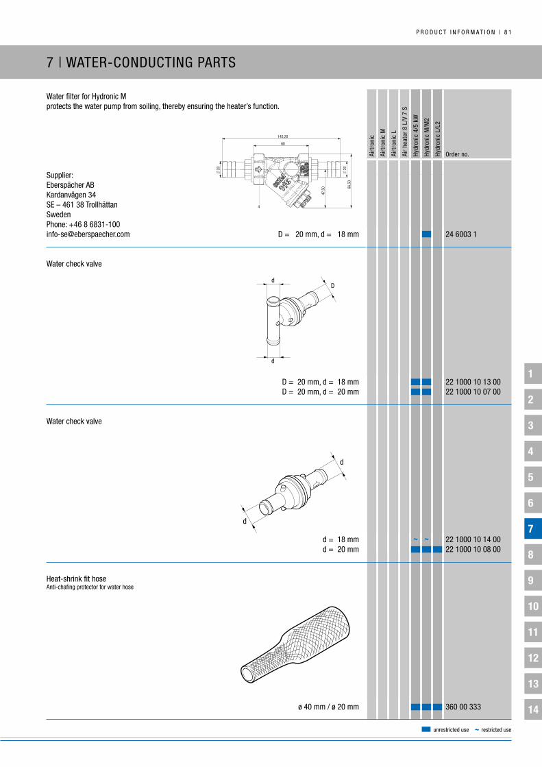
1
2
3
4
5
6
7
8
9
10
11
12
13
14
P R O D u C T i n F O R M A T i O n | 8 1
Airt
roni
c
Airt
roni
c M
Airt
roni
c L
Air
heat
er 8
L/V
7 S
Hydr
onic
4/5
kW
Hydr
onic
M/M
2
Hydr
onic
L/L
2
Order no.
unrestricted use ~ restricted use
Water filter for Hydronic Mprotects the water pump from soiling, thereby ensuring the heater’s function.
Supplier:Eberspächer Abkardanvägen 34SE – 461 38 TrollhättanSwedenPhone: +46 8 [email protected] D = 20 mm, d = 18 mm 24 6003 1
Water check valve
D = 20 mm, d = 18 mm 22 1000 10 13 00 D = 20 mm, d = 20 mm 22 1000 10 07 00
Water check valve
d = 18 mm 22 1000 10 14 00 d = 20 mm 22 1000 10 08 00
Heat-shrink fit hoseAnti-chafing protector for water hose
ø 40 mm / ø 20 mm 360 00 333
7 | WATER-COnDuCTing PARTS
68
66,
50
47,
50
20
20
145,20
CH. 22
CH. 34
36
40°12
36
16,50
16,2
0
16,2
0
2
34
7
8Pos Q.tà Description Material Finishing Drawing Code
9 2 HOSE UNION ROMA TYPE CW617N-M 33469/0 460000072909
8 1 SCREW STEEL ZINC Pltd. 33458/0 260000094909
7 2 MAGNET 32141/0 460000018309
6 1 O-RING 10.82X1.78 HNBR 70Sh 33457/0 370000096409
5 1 PLUG CW617N-M 12161/3 660000005509
4 1 BONNET CW617N-M 33461/0 220028102045
3 1 O-RING 28.3X1.78 RED FKM70 Red 32903/0 370000093309
2 1 STRAINER INOX R.0,25 AISI304 15537/1 260000008109
1 1 BODY CW511L 32927/1 210023102005
74AGCRNL/8 3/4X20
a
b
c
d
e
f
g
. . . .
33470/0OBLIQUE STRAINER FOR GAS WTH HOSE UNION
.
.
.
.
.
.
.
.
.
.
.
.
.
.
.
.
.
.
.
.
.
.
.
.
3D/\\
SERV
ERUT
\Dat
i-UT\
3d_s
w\P
RODU
ZION
E\PP
TEM
P\
4
~ ~

1
2
3
4
5
6
7
8
9
10
11
12
13
14
8 2 | P R O D u C T i n F O R M A T i O n
7 | WATER-COnDuCTing PARTS
Airt
roni
c
Airt
roni
c M
Airt
roni
c L
Air
heat
er 8
L/V
7 S
Hydr
onic
4/5
kW
Hydr
onic
M/M
2
Hydr
onic
L/L
2
Order no.
Safety hoseAluminum / paper / plastic temperature / anti-chafing protectorfor water hoses with ø 18 mm and ø 20 mm
di = 30 mm, L = 2 m 10 2114 25 02 00
unrestricted use ~ restricted use

1
2
3
4
5
6
7
8
9
10
11
12
13
14
P R O D u C T i n F O R M A T i O n | 8 3
Airt
roni
c
Airt
roni
c M
Airt
roni
c L
Air
heat
er 8
L/V
7 S
Hydr
onic
4/5
kW
Hydr
onic
M/M
2
Hydr
onic
L/L
2
Order no.
unrestricted use ~ restricted use
gEnERAL inFORMATiOn:
Heating-air throughput is at its highest in a heater if the airflow is
unimpeded. Heating-air ducts reduce heating-air throughput.
in order to give you the opportunity to check that the installation
you have planned does not reduce the heating air throughput to an
inadmissible level, we have calculated a heater guide number for
each heater and a line guide number for each air duct.
The total of the line guide numbers of the heating-air ducts
connected to the heater must not be greater than the heater
guide number, as otherwise the air flow temperature would be
inadmissibly high and the overheating sensor would respond.
if the total of the line guide numbers is greater than the heater guide
number, the total can be reduced by selecting a larger diameter for
the air ducts.
With smooth welded pipes, the line guide number is only half of the
flexible hose with the same diameter (i.e. double pipe length).
8 | AiR-COnDuCTing PARTS
RuLE OF THuMb:
Double cross-section or two lines the same, routed in parallel
= 1 / 4 of the guide number.
Example:
Hose ø 60 mm
Cross-section A = 19.6 cm2, guide number 1.0
Hose ø 75,
Cross-section A = 44.2 cm2, guide number 0.25

1
2
3
4
5
6
7
8
9
10
11
12
13
14
8 4 | P R O D u C T i n F O R M A T i O n
Airt
roni
c
Airt
roni
c M
Airt
roni
c L
Air
heat
er 8
L/V
7 S
Hydr
onic
4/5
kW
Hydr
onic
M/M
2
Hydr
onic
L/L
2
Order no.
unrestricted use ~ restricted use
di
L
D
L1
di
D
60060
di�
➀
di
➀1Flexible hose (linear m) Aluminum / paper / plastic, for heating-air ducting in interior
di = 50 mm 10 2114 29 00 00 di = 60 mm 10 2114 31 00 00 di = 75 mm 10 2114 34 00 00 di = 90 mm 10 2114 37 00 00 di = 100 mm 10 2114 38 00 00
2Flexible hosePlastic hose with metal spiral, suitable for outside installation
di = 60 mm, (1-meter pieces) 360 00 165 di = 75 mm, (linear m, max. 4 m long) 360 00 012 di = 90 mm, (linear m, max. 4 m long) 360 00 013 di = 100 mm, (linear m, max. 4 m long) 360 00 014
3SilencerHot air, aluminum
di = 75 mm, D = 120 mm 25 1226 89 15 00 di = 90 mm, D = 140 mm 25 1226 89 17 00 di = 100 mm, D = 150 mm 25 1226 89 56 00
4intake silencerAluminum / paper / plastic heating-air intake
di = 75 mm, D = 110 mm, L = 600 mm, L1 = 300 mm 330 00 072
~ ~~ ~
~~
~ ~
~~ ~
~~
~~ ~
➀
See page 126 for air hose clips
~ = Check connection diameter
~ = Check connection diameter
8 | AiR-COnDuCTing PARTS
➀
See page 126 for air hose clips
~ = Check connection diameter
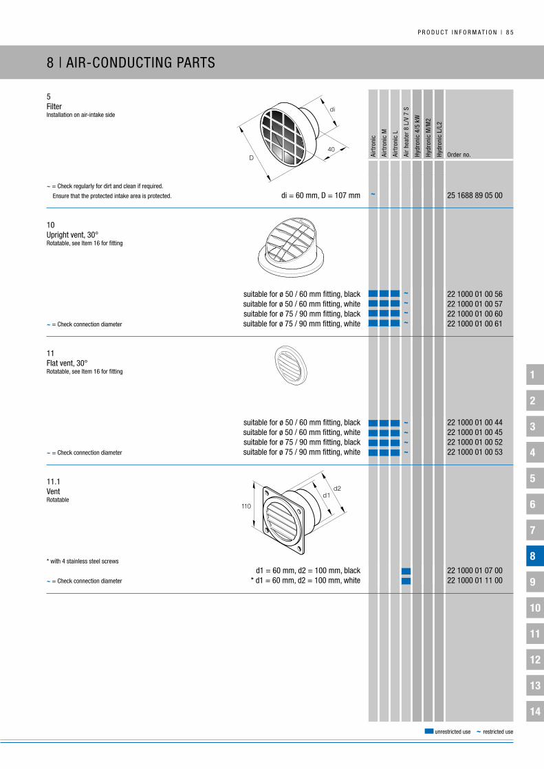
1
2
3
4
5
6
7
8
9
10
11
12
13
14
P R O D u C T i n F O R M A T i O n | 8 5
Airt
roni
c
Airt
roni
c M
Airt
roni
c L
Air
heat
er 8
L/V
7 S
Hydr
onic
4/5
kW
Hydr
onic
M/M
2
Hydr
onic
L/L
2
Order no.
unrestricted use ~ restricted use
5Filterinstallation on air-intake side
di = 60 mm, D = 107 mm 25 1688 89 05 00
10upright vent, 30°Rotatable, see item 16 for fitting
suitable for ø 50 / 60 mm fitting, black 22 1000 01 00 56 suitable for ø 50 / 60 mm fitting, white 22 1000 01 00 57 suitable for ø 75 / 90 mm fitting, black 22 1000 01 00 60 suitable for ø 75 / 90 mm fitting, white 22 1000 01 00 61
11Flat vent, 30°Rotatable, see item 16 for fitting
suitable for ø 50 / 60 mm fitting, black 22 1000 01 00 44 suitable for ø 50 / 60 mm fitting, white 22 1000 01 00 45 suitable for ø 75 / 90 mm fitting, black 22 1000 01 00 52 suitable for ø 75 / 90 mm fitting, white 22 1000 01 00 53
11.1VentRotatable
d1 = 60 mm, d2 = 100 mm, black 22 1000 01 07 00 * d1 = 60 mm, d2 = 100 mm, white 22 1000 01 11 00
~~ = Check regularly for dirt and clean if required.
Ensure that the protected intake area is protected.
* with 4 stainless steel screws
~ = Check connection diameter
D40
di
8 | AiR-COnDuCTing PARTS
~~~~
~~~~~ = Check connection diameter
~ = Check connection diameter
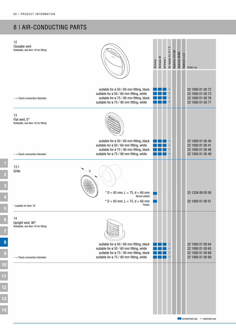
1
2
3
4
5
6
7
8
9
10
11
12
13
14
8 6 | P R O D u C T i n F O R M A T i O n
Airt
roni
c
Airt
roni
c M
Airt
roni
c L
Air
heat
er 8
L/V
7 S
Hydr
onic
4/5
kW
Hydr
onic
M/M
2
Hydr
onic
L/L
2
Order no.
unrestricted use ~ restricted use
8 | AiR-COnDuCTing PARTS
12Closable ventRotatable, see item 16 for fitting
suitable for ø 50 / 60 mm fitting, black 22 1000 01 00 72 suitable for ø 50 / 60 mm fitting, white 22 1000 01 00 73 suitable for ø 75 / 90 mm fitting, black 22 1000 01 00 76 suitable for ø 75 / 90 mm fitting, white 22 1000 01 00 77
13Flat vent, 0°Rotatable, see item 16 for fitting
suitable for ø 50 / 60 mm fitting, black 22 1000 01 00 40 suitable for ø 50 / 60 mm fitting, white 22 1000 01 00 41 suitable for ø 75 / 90 mm fitting, black 22 1000 01 00 48 suitable for ø 75 / 90 mm fitting, white 22 1000 01 00 49 13.1grille
* D = 93 mm, L = 75, d = 60 mm 25 1226 89 05 00 nickel-plated
* D = 93 mm, L = 75, d = 60 mm 22 1000 01 00 01 Plastic
14upright vent, 90°Rotatable, see item 16 for fitting
suitable for ø 50 / 60 mm fitting, black 22 1000 01 00 64 suitable for ø 50 / 60 mm fitting, white 22 1000 01 00 65 suitable for ø 75 / 90 mm fitting, black 22 1000 01 00 68 suitable for ø 75 / 90 mm fitting, white 22 1000 01 00 69
* suitable for item 18
~~~~
~~~~
~ = Check connection diameter
~ = Check connection diameter
~ = Check connection diameter
~~~~

1
2
3
4
5
6
7
8
9
10
11
12
13
14
P R O D u C T i n F O R M A T i O n | 8 7
Airt
roni
c
Airt
roni
c M
Airt
roni
c L
Air
heat
er 8
L/V
7 S
Hydr
onic
4/5
kW
Hydr
onic
M/M
2
Hydr
onic
L/L
2
Order no.
unrestricted use ~ restricted use
8 | AiR-COnDuCTing PARTS
15 Air control elementSee page 40
* Plastic, ø 60 mm 22 1000 01 00 79 ** Plastic, ø 75 mm 22 1000 01 00 80 *** Plastic, ø 90 mm 22 1000 01 00 81
16 Fittingfor vents, items 10, 11, 12, 13 and 14
d = 50 mm, d1 = 67 mm, D = 89 mm, L = 39 mm, black 22 1000 01 00 34 d = 60 mm, d1 = 67 mm, D = 89 mm, L = 40 mm, black 22 1000 01 00 35 d = 75 mm, d1 = 92 mm, D = 115 mm, L = 42 mm, black 22 1000 01 00 36 d = 90 mm, d1 = 92 mm, D = 115 mm, L = 40 mm, black 22 1000 01 00 37
17grille, heater
* di = 60 mm, L = 20 mm 25 1688 80 06 00 * di = 75 mm, L = 22 mm 25 1552 05 01 00 di = 90 mm, L = 24 mm 25 1729 80 00 01 di = 100 mm, L = 22 mm 25 1226 89 44 00
18Hose fittingSuitable for grille, item 13.1*
d = 50 mm, D = 97 mm, L = 75 20 1575 80 08 01 d = 60 mm, D = 97 mm, L = 75 20 1577 89 06 01
~ = Check connection diameter
d1 = core drill bit diameter
* for fitting, item 16, order no. 22 1000 01 00 35
** for fitting, item 16, order no. 22 1000 01 00 36
*** for fitting, item 16, order no. 22 1000 01 00 37
~~
~ ~~ = Check connection diameter
L
di
* D = 93 mm
~ = Check connection diameter
~~
d
50D
L
~~~~
~~~

1
2
3
4
5
6
7
8
9
10
11
12
13
14
8 8 | P R O D u C T i n F O R M A T i O n
Airt
roni
c
Airt
roni
c M
Airt
roni
c L
Air
heat
er 8
L/V
7 S
Hydr
onic
4/5
kW
Hydr
onic
M/M
2
Hydr
onic
L/L
2
Order no.
unrestricted use ~ restricted use
8 | AiR-COnDuCTing PARTS
21Scoop
d = 60 mm 22 1000 01 00 16 d = 75 mm 22 1000 01 00 17 d = 75 mm 22 1000 01 00 18 d = 90 mm 22 1000 01 00 19
22Scoop
d = 90 mm 25 1729 01 09 00
30ball-shaped scoop
d = 90 mm 25 1729 89 10 00
31 Connection fittingball-shaped scoop, item 30 / 32
d = 25 mm 20 1575 89 00 15 d = 50 mm 22 1000 01 00 04
32ball-shaped scoop
d = 60 mm 22 1000 01 00 20 d = 75 mm 22 1000 01 00 28 * d = 75 mm 22 1000 01 00 22 * d = 90 mm 22 1000 01 00 23
➀
Connection fitting, see item 31
~ ~ ~~
Caution! Make sure the line guide number is not too high
➀
Connection fitting for item 31
* Cannot be used with the Airtronic D4 Plus d
d
➀

1
2
3
4
5
6
7
8
9
10
11
12
13
14
P R O D u C T i n F O R M A T i O n | 8 9
Airt
roni
c
Airt
roni
c M
Airt
roni
c L
Air
heat
er 8
L/V
7 S
Hydr
onic
4/5
kW
Hydr
onic
M/M
2
Hydr
onic
L/L
2
Order no.
unrestricted use ~ restricted use
8 | AiR-COnDuCTing PARTS
33Pipe elbow, 90°
di = 60 mm, da = 60 mm 25 1688 89 00 01 di = 75 mm, da = 75 mm 25 1482 89 00 05
34Ring
Protective grille (item 17), di = 90 mm.
Can be used as an adapter – remove grille.
di = 60 mm, da = 75 mm 22 1000 01 00 08 di = 75 mm, da = 90 mm 25 1822 89 00 01 di = 90 mm, da = 100 mm 20 1607 80 00 01
35T-junction
Metal, d = 50 mm 20 1575 89 18 00 Plastic, d = 60 mm 25 1688 89 00 02 Plastic, d = 75 mm 22 1000 01 00 27 Plastic, d = 90 mm 22 1000 01 00 26 Metal, d = 100 mm 20 1667 89 03 00
40butterfly valve
d = 60 mm 330 00 174 d = 90 mm 330 00 175
da
di
➀
~ ~
~ ~
~
➀
Adapter, see item 45
~ = Check connection diameter
~ = Check connection diameter

1
2
3
4
5
6
7
8
9
10
11
12
13
14
9 0 | P R O D u C T i n F O R M A T i O n
Airt
roni
c
Airt
roni
c M
Airt
roni
c L
Air
heat
er 8
L/V
7 S
Hydr
onic
4/5
kW
Hydr
onic
M/M
2
Hydr
onic
L/L
2
Order no.
unrestricted use ~ restricted use
8 | AiR-COnDuCTing PARTS
41Control unitFor butterfly valve, item 40, 2 m long
22 1000 01 03 00
42y-junctionSymmetrical
Plastic, D = 60 mm, d = 50 mm 25 1688 89 00 03 Plastic, D = 75 mm, d = 60 mm 22 1000 01 00 82 Plastic, D = 90 mm, d = 60 mm 22 1000 01 00 83 Plastic, D = 90 mm, d = 75 mm 22 1000 01 00 84
42.1y-junction
Metal, D = 75 mm, d = 50 mm 25 1482 80 08 00
43y-junction
d = 60, L = 145 mm 25 1774 89 00 05 d = 75, L = 175 mm 25 1226 89 00 44 d = 90, L = 180 mm 22 1000 01 00 21 d = 100, L = 230 mm 25 1226 89 00 45
44Hose connector fitting
d = 60 mm 22 1000 01 00 05 d = 75 mm 22 1000 01 00 06 d = 90 mm 22 1000 01 00 24 d = 100 mm 22 1000 01 00 07
~ = Check connection diameter
~ = Check connection diameter ~
~
➀
Adapter, see item 45
~ = Check connection diameter
➀
Adapter, see item 45
~ = Check connection diameter
~ ~~ ~ ~
~ ~
~ ~ ~~ ~ ~
~ ~
d
➀
➀
D
d
d

1
2
3
4
5
6
7
8
9
10
11
12
13
14
P R O D u C T i n F O R M A T i O n | 9 1
Airt
roni
c
Airt
roni
c M
Airt
roni
c L
Air
heat
er 8
L/V
7 S
Hydr
onic
4/5
kW
Hydr
onic
M/M
2
Hydr
onic
L/L
2
Order no.
unrestricted use ~ restricted use
8 | AiR-COnDuCTing PARTS
45AdapterFor item 40, 43 and 44
di = 75 mm, da = 50 mm, L = 50 mm 25 1226 89 00 46 di = 75 mm, da = 60 mm, L = 45 mm 25 1226 89 00 50 di = 90 mm, da = 75 mm, L = 45 mm 22 1000 01 00 12 di = 100 mm, da = 50 mm, L = 62 mm 25 1226 89 00 48 di = 100 mm, da = 60 mm, L = 57 mm 25 1226 89 00 51 di = 100 mm, da = 75 mm, L = 50 mm 25 1226 89 00 47 di = 100 mm, da = 90 mm, L = 42 mm 25 1226 89 00 49
46Adapter
di = 60 mm, da = 75 mm, L = 40.5 mm 25 1688 89 00 10
47Adapter
Plastic, di = 75 mm, D = 90 mm, L = 54 mm 22 1000 01 00 85 Metal, di = 90 mm, D = 100 mm, L = 46 mm 20 1462 89 00 01
48Sleeve / adapter
d = 90 mm / 100 mm 20 1607 80 00 01
~ = Check connection diameter
~~
~ ~~ ~~ ~
~ ~ ~~ ~
~
da
Ldi
~ = Check connection diameter
~
~
d
~ = Check connection diameter
~ = Check connection diameter

1
2
3
4
5
6
7
8
9
10
11
12
13
14
9 2 | P R O D u C T i n F O R M A T i O n
Airt
roni
c
Airt
roni
c M
Airt
roni
c L
Air
heat
er 8
L/V
7 S
Hydr
onic
4/5
kW
Hydr
onic
M/M
2
Hydr
onic
L/L
2
Order no.
unrestricted use ~ restricted use
9 | FuEL-COnDuCTing PARTS
gEnERAL inFORMATiOn:
Protect fuel lines, filters and metering pumps from impermissible heat levels; do not install near control dampers and exhaust pipes.
Take the rear axle suspension into account when installing fuel lines, fuel filters and metering pumps near the rear axle.
When cutting fuel hoses and types, be sure to use a sharp knife.
Cut surfaces must have no dents or burrs.
Please also refer to the safety information on this section in the heater documentation.

1
2
3
4
5
6
7
8
9
10
11
12
13
14
P R O D u C T i n F O R M A T i O n | 9 3
Airt
roni
c
Airt
roni
c M
Airt
roni
c L
Air
heat
er 8
L/V
7 S
Hydr
onic
4/5
kW
Hydr
onic
M/M
2
Hydr
onic
L/L
2
Order no.
unrestricted use ~ restricted use
9 | FuEL-COnDuCTing PARTS
Tank connectionFor cars with an inner tank pump
➀ da = 4 mm, di = 2 mm 22 1000 20 15 00 ➁ da = 4 mm, di = 2 mm, L = 295 mm 22 1000 20 16 00
Tank connection with returnFor commercial vehicles
da = 6 mm, di = 4 mm 25 1226 89 40 00
Tank connectionFor commercial vehicles
da = 6 mm, di = 2 mm 25 1226 89 50 00 da = 6 mm, di = 4 mm 25 1156 30 00 00
kit – fuel lines for E85Only for Hydronic 2 – b5 S
l1 = ø 4x1.25 pipe; L = 6 m, black / l2 = ø 4x1 pipe; L = 2 m, black 22 1000 20 31 00
Tank connection kitFor cars with an inner tank pump
l1 = ø 4x1.25 pipe; L = 6 m / l2 = ø 4x1 pipe; L = 6 m / da = 4 mm, di = 2 mm 22 1000 20 13 00
~
➀ ➁

1
2
3
4
5
6
7
8
9
10
11
12
13
14
9 4 | P R O D u C T i n F O R M A T i O n
Airt
roni
c
Airt
roni
c M
Airt
roni
c L
Air
heat
er 8
L/V
7 S
Hydr
onic
4/5
kW
Hydr
onic
M/M
2
Hydr
onic
L/L
2
Order no.
unrestricted use ~ restricted use
9 | FuEL-COnDuCTing PARTS
Fuel supply kitFor installation in the tank ventilation hose
l1 = ø 4x1 steel pipe, L = 1 m / l2 = ø 4x1 plastic pipe, L = 2 m 22 1000 20 06 00
Fuel supply kitTank extraction feed line
l1 = ø 4x1.25 pipe; L = 6 m / l2 = ø 6x1 pipe; L = 2 m 22 1000 20 17 00
Fuel hose (linear m)Rubber
di = 3.5 mm, D = 9.50 mm 360 75 300 * di = 3.5 mm, D = 9.50 mm 360 75 400 di = 5.0 mm, D = 11.0 mm 360 75 350 * di = 5.0 mm, D = 11.0 mm 360 75 401 * di = 7.5 mm, D = 13.5 mm 360 75 402 * di = 9.0 mm, D = 15.0 mm 360 75 404* PME-compatible
~ ~ ~ ~ ~ ~~ ~ ~ ~ ~ ~

1
2
3
4
5
6
7
8
9
10
11
12
13
14
P R O D u C T i n F O R M A T i O n | 9 5
Airt
roni
c
Airt
roni
c M
Airt
roni
c L
Air
heat
er 8
L/V
7 S
Hydr
onic
4/5
kW
Hydr
onic
M/M
2
Hydr
onic
L/L
2
Order no.
unrestricted use ~ restricted use
9 | FuEL-COnDuCTing PARTS
Fuel supply kitFor installing fuel line in boat engine compartments
22 1000 20 10 00
Fuel hose 105° elbowPME-compatible
di = 3.5 mm, D = 9.5 mm 25 1888 80 01 01
Hydronic S3 adapter
Outer diameter D = 10 22 1000 20 38 00
Hydronic S3 adapter elbow
D = 9.5 mm, di1 = 4.5 mm, di2 = 3.5 mm 22 1000 20 41 00
Adapter
Outer diameter D = 10 25 1888 80 01 02
Adapter 105° elbowPME-compatible
Outer diameter D = 10 25 2110 05 03 01
Adapter for fuel pipes
Outer diameter D = 12 22 1000 20 30 00
Fire-resistant hose according to Din En iSO 14859
5
3,5
50
50
~ = Check connection diameter
di
D
4,5
3,5
5
3,5
��
48
~
~
5
3,5
405
3,5
5
3,5
~ = Check connection diameter

1
2
3
4
5
6
7
8
9
10
11
12
13
14
9 6 | P R O D u C T i n F O R M A T i O n
Airt
roni
c
Airt
roni
c M
Airt
roni
c L
Air
heat
er 8
L/V
7 S
Hydr
onic
4/5
kW
Hydr
onic
M/M
2
Hydr
onic
L/L
2
Order no.
unrestricted use ~ restricted use
9 | FuEL-COnDuCTing PARTS
Fuel pipe (linear m)Plastic
natural-colored, di = 1.5 mm , D = 4 mm 890 31 118 natural-colored, di = 2 mm , D = 4 mm 890 31 055 Ethanol resistant, di = 1.5 mm , D = 4 mm 890 31 139 Ethanol resistant, di = 2 mm , D = 4 mm 890 31 138 blue, di = 2 mm , D = 4 mm 890 31 054 black, di = 2 mm , D = 6 mm 890 31 125 blue, di = 4 mm , D = 6 mm 890 31 101
Foam rubber hose (linear m)Chafing protection and soundproofing for fuel pipe
di = 5 mm, D = 11 mm 360 75 200
Heat protection hoseFor fuel pipeAluminum clad with fiberglass clothAlso suitable for electrical cabling
di = 10 mm, D = 13 mm 360 00 183
Reinforcing sleevebrass, for plastic fuel pipes10 per pack
da = 4 mm 22 1000 20 01 00 for 06x1 pipe da = 6 mm 22 1000 20 02 00 for 08x1 pipe da = 8 mm 22 1000 20 03 00 for 10x1 pipe
Hose nippleStraight, for M 10 x 1 union nut
25 1351 88 01 01
da
di
D
355
~~
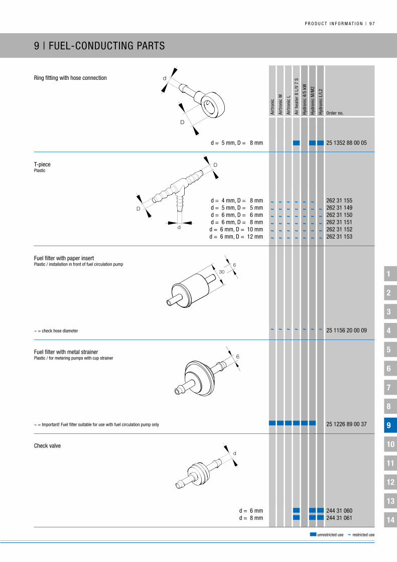
1
2
3
4
5
6
7
8
9
10
11
12
13
14
P R O D u C T i n F O R M A T i O n | 9 7
Airt
roni
c
Airt
roni
c M
Airt
roni
c L
Air
heat
er 8
L/V
7 S
Hydr
onic
4/5
kW
Hydr
onic
M/M
2
Hydr
onic
L/L
2
Order no.
unrestricted use ~ restricted use
Ring fitting with hose connection
d = 5 mm, D = 8 mm 25 1352 88 00 05
T-piecePlastic
d = 4 mm, D = 8 mm 262 31 155 d = 5 mm, D = 5 mm 262 31 149 d = 6 mm, D = 6 mm 262 31 150 d = 6 mm, D = 8 mm 262 31 151 d = 6 mm, D = 10 mm 262 31 152 d = 6 mm, D = 12 mm 262 31 153
Fuel filter with paper insert Plastic / installation in front of fuel circulation pump
25 1156 20 00 09
Fuel filter with metal strainerPlastic / for metering pumps with cup strainer
25 1226 89 00 37
Check valve
d = 6 mm 244 31 060 d = 8 mm 244 31 061
~ = important! Fuel filter suitable for use with fuel circulation pump only
~ ~ ~ ~ ~ ~ ~
~ ~ ~ ~ ~ ~~ ~ ~ ~ ~ ~ ~~ ~ ~ ~ ~ ~ ~~ ~ ~ ~ ~ ~ ~~ ~ ~ ~ ~ ~ ~~ ~ ~ ~ ~ ~ ~
~ = check hose diameter
D
D
d
9 | FuEL-COnDuCTing PARTS
d
D
d

1
2
3
4
5
6
7
8
9
10
11
12
13
14
9 8 | P R O D u C T i n F O R M A T i O n
Airt
roni
c
Airt
roni
c M
Airt
roni
c L
Air
heat
er 8
L/V
7 S
Hydr
onic
4/5
kW
Hydr
onic
M/M
2
Hydr
onic
L/L
2
Order no.
unrestricted use ~ restricted use
Pressure reducerwith cup strainer and hose fittinginput pressure 0.2 – 4 barControl pressure min. 50 mbar, max. 150 mbar
22 1000 20 08 00
Complete fuel tank, 10 lPlastic
22 1000 20 28 00
Complete fuel tank, 10 l – single partLidPlastic
22 1000 20 22 00
Complete fuel tank, 10 l – single partFuel strainer
22 1000 20 28 03
Complete fuel tank, 10 l – single partSeal
22 1000 20 28 04
~ = Only suitable for diesel / bio-diesel (FAME) / heating oil ~ ~ ~ ~ ~ ~ ~
78
405
405
450
9 | FuEL-COnDuCTing PARTS
~ ~ ~ ~ ~ ~ ~
~ ~ ~ ~ ~ ~ ~
~ ~ ~ ~ ~ ~ ~

1
2
3
4
5
6
7
8
9
10
11
12
13
14
P R O D u C T i n F O R M A T i O n | 9 9
Airt
roni
c
Airt
roni
c M
Airt
roni
c L
Air
heat
er 8
L/V
7 S
Hydr
onic
4/5
kW
Hydr
onic
M/M
2
Hydr
onic
L/L
2
Order no.
unrestricted use ~ restricted use
10 | ELECTRiCAL PARTS / TESTing EquiPMEnT
gEnERAL inFORMATiOn:
using a timer you can manually or automatically switch on the heater at a preset time (pre-heating mode).
Always make sure that a heater can run on, even if the vehicle's whole electrical system can be shut down with a battery main switch (i.e. via an additional electrical connection or clear instruction that the battery main switch should be open when the heater is running with a flame).
The rule of thumb for the electrical power supply is: charging time = heating time.
in certain circumstances, heaters in motor homes or commercial vehicles are operated for longer sustained periods. in these cases, the on-board energy resources need to be monitored.
For more detailed information, see technical description and installation instructions.
Please also refer to the safety information on this section in the heater documentation.

1
2
3
4
5
6
7
8
9
10
11
12
13
14
1 0 0 | P R O D u C T i n F O R M A T i O n
Airt
roni
c
Airt
roni
c M
Airt
roni
c L
Air
heat
er 8
L/V
7 S
Hydr
onic
4/5
kW
Hydr
onic
M/M
2
Hydr
onic
L/L
2
Order no.
unrestricted use ~ restricted use
EasyStart Remote+Remote control
12 V / 24 V 22 1000 34 17 00
EasyStart Remote*Remote control
12 V / 24 V 22 1000 34 23 00
EasyStart Timer
12 V / 24 V 22 1000 34 15 00
EasyStart Select
12 V / 24 V 22 1000 34 13 00
~
~ ~ ~ ~
~
Timer trim for EasyStart Timer, see page 131
~ = heater operation only, no diagnostics
* with Airtronic: additional control unit required for temperature preselection
10 | ELECTRiCAL PARTS

1
2
3
4
5
6
7
8
9
10
11
12
13
14
P R O D u C T i n F O R M A T i O n | 1 0 1
Airt
roni
c
Airt
roni
c M
Airt
roni
c L
Air
heat
er 8
L/V
7 S
Hydr
onic
4/5
kW
Hydr
onic
M/M
2
Hydr
onic
L/L
2
Order no.
unrestricted use ~ restricted use
EasyStart WebWeb-based remote operation
12 V / 24 V 22 1000 34 51 00
EasyStart Remote+ – single partMobile part
12 V / 24 V 22 1000 34 18 00
EasyStart Remote+ – single partFixed part
12 V / 24 V 22 1000 34 19 00
EasyStart Remote+ – single part Sensor – interior temperature, display
22 1000 34 22 00
EasyStart Remote – single partMobile part
12 V / 24 V 22 1000 34 24 00
~
~
~
10 | ELECTRiCAL PARTS

1
2
3
4
5
6
7
8
9
10
11
12
13
14
1 0 2 | P R O D u C T i n F O R M A T i O n
Airt
roni
c
Airt
roni
c M
Airt
roni
c L
Air
heat
er 8
L/V
7 S
Hydr
onic
4/5
kW
Hydr
onic
M/M
2
Hydr
onic
L/L
2
Order no.
unrestricted use ~ restricted use
10 | ELECTRiCAL PARTS
EasyStart Remote – single partFixed part
12 V / 24 V 22 1000 34 25 00
EasyStart Remote+ / EasyStart Remote – single part Cover for battery compartment
EasyStart Remote+ 22 1000 34 18 01 EasyStart Remote 22 1000 34 24 01
EasyStart Remote+ / EasyStart Remote – single part Antenna
22 1000 34 21 00
EasyStart Remote+ / EasyStart Remote – single part button
22 1000 34 20 00
EasyStart Call / EasyStart Remote+ / EasyStart Remote / EasyStart Timer / EasyStart Select – single part Electrical connection parts
22 1000 34 26 00
~
~ ~ ~ ~

1
2
3
4
5
6
7
8
9
10
11
12
13
14
P R O D u C T i n F O R M A T i O n | 1 0 3
Airt
roni
c
Airt
roni
c M
Airt
roni
c L
Air
heat
er 8
L/V
7 S
Hydr
onic
4/5
kW
Hydr
onic
M/M
2
Hydr
onic
L/L
2
Order no.
unrestricted use ~ restricted use
EasyStart Select – single part Plugs
22 1000 34 13 01
EasyStart Call – single part Slide antenna
22 1000 34 03 00
EasyStart Call – single part button
22 1000 34 04 00
EasyStart Call – single part Temperature sensor
22 1000 34 09 00
EasyStart Call, EasyStart Remote+ / EasyStart Remote / EasyStart Timer – single part Adapter cable
EasyStart Remote / EasyStart Remote+ / EasyStart Call (12-pin) 22 1000 34 08 00 EasyStart Timer (10-pin) 22 1000 34 45 00
10 | ELECTRiCAL PARTS

1
2
3
4
5
6
7
8
9
10
11
12
13
14
1 0 4 | P R O D u C T i n F O R M A T i O n
Airt
roni
c
Airt
roni
c M
Airt
roni
c L
Air
heat
er 8
L/V
7 S
Hydr
onic
4/5
kW
Hydr
onic
M/M
2
Hydr
onic
L/L
2
Order no.
unrestricted use ~ restricted use
10 | ELECTRiCAL PARTS
EasyStart R+ – single part Mobile part
12 V / 24 V 22 1000 32 81 00
EasyStart R+ – single part Fixed part
22 1000 32 82 00
EasyStart R – single part
12 V / 24 V 22 1000 32 86 00
EasyStart R – single part Fixed part
22 1000 32 87 00
EasyStart R+ / EasyStart R – single part Cover for battery compartment
22 1000 32 91 00
~
~
~
~
~
Spare part for 22 1000 32 80 00
Spare part for 22 1000 32 80 00
Spare part for 22 1000 32 85 00
Spare part for 22 1000 32 85 00
Spare part for 22 1000 32 80 00 and 22 1000 32 85 00

1
2
3
4
5
6
7
8
9
10
11
12
13
14
P R O D u C T i n F O R M A T i O n | 1 0 5
Airt
roni
c
Airt
roni
c M
Airt
roni
c L
Air
heat
er 8
L/V
7 S
Hydr
onic
4/5
kW
Hydr
onic
M/M
2
Hydr
onic
L/L
2
Order no.
unrestricted use ~ restricted use
10 | ELECTRiCAL PARTS
EasyStart R+ / EasyStart R – single part Antenna
22 1000 32 83 00
EasyStart R+ / EasyStart R – single part Electrical connection parts
22 1000 32 90 00
EasyStart R+ / EasyStart R / EasyStart T – single part button
22 1000 32 84 00
EasyStart R+ / EasyStart R / EasyStart T – single part Electrical connection parts
22 1000 32 92 00
EasyStart R+ / EasyStart T – single part Sensor – interior temperature, display
22 1000 32 97 00
Spare part for 22 1000 32 80 00 and 22 1000 32 85 00
Spare part for 22 1000 32 80 00 and 22 1000 32 85 00
Spare part for 22 1000 32 80 00, 22 1000 32 85 00 and 22 1000 32 88 00
Spare part for 22 1000 32 80 00, 22 1000 32 85 00 and 22 1000 32 88 00
Spare part for 22 1000 32 80 00 and 22 1000 32 88 00

1
2
3
4
5
6
7
8
9
10
11
12
13
14
1 0 6 | P R O D u C T i n F O R M A T i O n
Airt
roni
c
Airt
roni
c M
Airt
roni
c L
Air
heat
er 8
L/V
7 S
Hydr
onic
4/5
kW
Hydr
onic
M/M
2
Hydr
onic
L/L
2
Order no.
unrestricted use ~ restricted use
10 | ELECTRiCAL PARTS
Calltronic – single part Slide antenna
22 1000 33 63 00
Calltronic i – single part Slide antenna
22 1000 33 84 00

1
2
3
4
5
6
7
8
9
10
11
12
13
14
P R O D u C T i n F O R M A T i O n | 1 0 7
Airt
roni
c
Airt
roni
c M
Airt
roni
c L
Air
heat
er 8
L/V
7 S
Hydr
onic
4/5
kW
Hydr
onic
M/M
2
Hydr
onic
L/L
2
Order no.
unrestricted use ~ restricted use
Mini-controller – single part
22 1000 32 07 00
Control unit
* 12 V 25 1895 71 00 00 * 24 V 25 1896 71 00 00 ** 12 V 25 1767 71 00 00 ** 24 V 25 1768 71 00 00
Control unit – single part 7-pin bushing connector housing
206 31 282
Control unit – single part bushing connector
206 36 151
10 | ELECTRiCAL PARTS
~ ~
~ ~~ ~
~~
* with bushing connector housing and bushing connector
** without bushing connector housing and bushing connectors / only for air
heater 8 L
~ = no ventilation, no diagnostic information.

1
2
3
4
5
6
7
8
9
10
11
12
13
14
1 0 8 | P R O D u C T i n F O R M A T i O n
Airt
roni
c
Airt
roni
c M
Airt
roni
c L
Air
heat
er 8
L/V
7 S
Hydr
onic
4/5
kW
Hydr
onic
M/M
2
Hydr
onic
L/L
2
Order no.
unrestricted use ~ restricted use
External and internal temperature control sensor, flush wall-mounted installation2 m cable harness
22 1000 35 21 00
Exterior and interior temperature control sensor, surface installation2 m cable harness
25 1774 89 03 00
Cable harness / temperature sensorFor 25 1774 89 03 00
4 m, 2-pin 25 1688 89 09 00 4 m, 3-pin 25 1482 89 40 00
Additional heater installation kitOnly for Hydronic 2 in combination with EasyStart Remote+ / Remote / Timer
24 8532 00 00 00
Hydronic S3 Economy cable harnessfor recreational vehicles and boatsrequired for heating when using a mains connection (230 V/50 Hz), e.g. in camping or parking areas for mobile homes or in marinas for boats
25 2652 82 11 00
10 | ELECTRiCAL PARTS
~ = Can be used with control unit
~~ = Can be used with control unit
Thermostatic switch including connectors and fastenings
Switch-off point: 10°C
Switch-on point: 5°C
35
19
10 35
19
10
6000 mm
3050 mm
2700 mm
~
~
~~
~* available from 3rd quarter 2017

1
2
3
4
5
6
7
8
9
10
11
12
13
14
P R O D u C T i n F O R M A T i O n | 1 0 9
Airt
roni
c
Airt
roni
c M
Airt
roni
c L
Air
heat
er 8
L/V
7 S
Hydr
onic
4/5
kW
Hydr
onic
M/M
2
Hydr
onic
L/L
2
Order no.
unrestricted use ~ restricted use
10 | ELECTRiCAL PARTS
Voltage divider for fan control – single part Connector block
203 00 085
Voltage divider for fan control – single part bushing connector
203 53 020
iPCu retrofit kit
12 V 24 0273 00 00 00
iPCu retrofit kit – single partRelay
12 V 22 1000 32 73 00
~ = For customer-specific retrofit kits, see the Service Portal – EPRO / Accessories / Electrical parts ~ ~ ~ ~ ~ ~
~ ~ ~ ~ ~ ~
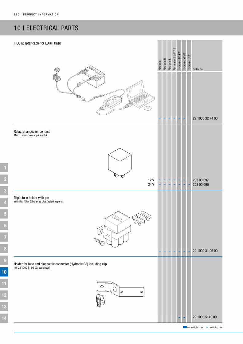
1
2
3
4
5
6
7
8
9
10
11
12
13
14
1 1 0 | P R O D u C T i n F O R M A T i O n
Airt
roni
c
Airt
roni
c M
Airt
roni
c L
Air
heat
er 8
L/V
7 S
Hydr
onic
4/5
kW
Hydr
onic
M/M
2
Hydr
onic
L/L
2
Order no.
unrestricted use ~ restricted use
10 | ELECTRiCAL PARTS
iPCu adapter cable for EDiTH basic
22 1000 32 74 00
Relay, changeover contactMax. current consumption 40 A
12 V 203 00 097 24 V 203 00 096
Triple fuse holder with pinWith 5 A, 15 A, 25 A fuses plus fastening parts
22 1000 31 06 00
Holder for fuse and diagnostic connector (Hydronic S3) including clip(for 22 1000 31 06 00; see above)
22 1000 5149 00
~ ~ ~ ~ ~ ~
~ ~ ~ ~ ~ ~~ ~ ~ ~ ~ ~ ~
~ ~ ~ ~ ~ ~ ~
~ ~
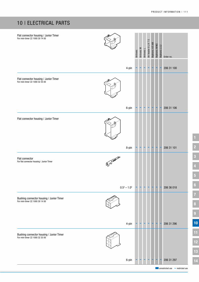
1
2
3
4
5
6
7
8
9
10
11
12
13
14
P R O D u C T i n F O R M A T i O n | 1 1 1
Airt
roni
c
Airt
roni
c M
Airt
roni
c L
Air
heat
er 8
L/V
7 S
Hydr
onic
4/5
kW
Hydr
onic
M/M
2
Hydr
onic
L/L
2
Order no.
unrestricted use ~ restricted use
10 | ELECTRiCAL PARTS
Flat connector housing / Junior TimerFor mini-timer 22 1000 30 14 00
4-pin 206 31 100
Flat connector housing / Junior TimerFor mini-timer 22 1000 32 35 00
6-pin 206 31 106
Flat connector housing / Junior Timer
8-pin 206 31 101
Flat connectorFor flat connector housing / Junior Timer
0.52 – 1.02 206 36 018
bushing connector housing / Junior TimerFor mini-timer 22 1000 30 14 00
4-pin 206 31 296
bushing connector housing / Junior TimerFor mini-timer 22 1000 32 35 00
6-pin 206 31 297
~ ~ ~ ~ ~ ~ ~
~ ~ ~ ~ ~ ~ ~
~ ~ ~ ~ ~ ~ ~
~ ~ ~ ~ ~ ~ ~
~ ~ ~ ~ ~ ~ ~
~ ~ ~ ~ ~ ~ ~

1
2
3
4
5
6
7
8
9
10
11
12
13
14
1 1 2 | P R O D u C T i n F O R M A T i O n
Airt
roni
c
Airt
roni
c M
Airt
roni
c L
Air
heat
er 8
L/V
7 S
Hydr
onic
4/5
kW
Hydr
onic
M/M
2
Hydr
onic
L/L
2
Order no.
unrestricted use ~ restricted use
10 | ELECTRiCAL PARTS
bushing connector housing / Junior Timer
8-pin 206 31 298
bushing connectorFor bushing connector housing / Junior Timer
0.52 – 1.02 206 73 052 1.02 – 2.52 206 73 053
Flat connector housing AMP 2.8
2-pin 206 31 018
Flat connectorFor flat connector housing AMP 2.8
0.52 – 1.02 206 73 001 1.02 – 2.52 206 52 151
bushing connector housing AMP 2.8
206 31 306
bushing connectorFor bushing connector housing AMP 2.8
0.52 – 1.02 206 73 039 1.02 – 2.52 206 36 161
8-pin bushing connector housing kitFor the Hydronic, with contacts and seals
22 1000 30 10 21
~ ~ ~ ~ ~ ~ ~
~ ~ ~ ~ ~ ~ ~
~ ~ ~ ~ ~ ~ ~
~ ~ ~ ~ ~ ~ ~~ ~ ~ ~ ~ ~ ~
~ ~ ~ ~ ~ ~ ~~ ~ ~ ~ ~ ~ ~
~ ~ ~ ~ ~ ~ ~~ ~ ~ ~ ~ ~ ~

1
2
3
4
5
6
7
8
9
10
11
12
13
14
P R O D u C T i n F O R M A T i O n | 1 1 3
Airt
roni
c
Airt
roni
c M
Airt
roni
c L
Air
heat
er 8
L/V
7 S
Hydr
onic
4/5
kW
Hydr
onic
M/M
2
Hydr
onic
L/L
2
Order no.
unrestricted use ~ restricted use
10 | ELECTRiCAL PARTS / TESTing EquiPMEnT
Connector housing kit for Hydronic S3for metering pump, with contacts and seals
22 1000 35 25 00
Connector housing kitFor metering pump, with contacts and seals
22 1000 31 87 00
Altitude kit *Air pressure sensor for heating mode at altitudesup to 3,500 m above sea level
22 1000 33 22 00
Adapter cable For air pressure sensor diagnostics
22 1000 33 31 00
Diagnostic device
22 1545 89 00 00
* For use with the Airtronic / Airtronic M and Hydronic / Hydronic 2
labeled “H-kit” on the factory plate on the side
~

1
2
3
4
5
6
7
8
9
10
11
12
13
14
1 1 4 | P R O D u C T i n F O R M A T i O n
Airt
roni
c
Airt
roni
c M
Airt
roni
c L
Air
heat
er 8
L/V
7 S
Hydr
onic
4/5
kW
Hydr
onic
M/M
2
Hydr
onic
L/L
2
Order no.
unrestricted use ~ restricted use
10 | TESTing EquiPMEnT
EasyScan
22 1550 89 0000
Adapter cable * Airtronic / Airtronic M 22 1000 31 86 00For diagnostic device and EDiTH basic and EasyScan Hydronic 22 1000 31 63 00 Hydronic 2 / Hydronic 2 C / Hydronic M2 (versions from June 2012) 22 1000 33 78 00 Hydronic L / Hydronic L2 22 1000 31 66 00 EasyStart Web 22 1000 34 11 00
Adapter cable for older models of heaterFor diagnostic device and EDiTH basic
Hydronic M 22 1000 32 52 00 Hydronic M2 (versions pre-dating June 2012) 22 1000 33 44 00 b / D1 LC compact, b / D3 LC compact, b / D3 LP compact 22 1000 30 69 00 b / D1 LC, b / D3 LC, b / D3 LP, b / D5 LC 22 1000 30 20 00 D9 W, Hydronic 10 22 1000 31 83 00
Adapter cableVehicle-specific, for diagnostic device and EDiTH basic
Toyota 22 1526 89 03 00 neoplan 22 1000 31 16 00
Adapter cable for older models of heater vehicle-specific for diagnostic device and EDiTH basic MAn b / D1 LC compact, b / D3 LC compact 22 1000 32 20 00 MAn b / D1 LC / D3 LC 22 1000 30 32 00 RVi b / D1 LC compact, b / D3 LC compact 22 1000 31 25 00 RVi D1 LC 22 1000 31 23 00 DAF b / D1 LC compact, b / D3 LC compact 22 1000 31 21 00
uSb to serial adapterincl. EDiTH diagnostic tool software CD
22 1543 89 00 00
* Cable harness with diagnostic connector
69,1
82
24
~ ~

P R O D u C T i n F O R M A T i O n | 1 1 5
1
2
3
4
5
6
7
8
9
10
11
12
13
14
1
2
3
4
5
6
7
8
9
10
11
12
13
14
1 1 6 | P R O D u C T i n F O R M A T i O n
Airt
roni
c
Airt
roni
c M
Airt
roni
c L
Air
heat
er 8
L/V
7 S
Hydr
onic
4/5
kW
Hydr
onic
M/M
2
Hydr
onic
L/L
2
Order no.
unrestricted use ~ restricted use
11 | ExHAuST-COnDuCTing AnD COMbuSTiOn-AiR-COnDuCTing PARTS
gEnERAL inFORMATiOn:
the exhaust and combustion air system must be installed in such a way that it ensures the following:
The connection to the heater plug is sealed.
The mouth of the pipe is never facing a head wind.
As far as possible, the mouth of the pipe is protected from spray water ingress and spray must be able to run straight out again without penetrating the heater.
There is no possibility of heater or vehicle engine exhaust gases being sucked in.
Please also refer to the safety information on this section in the heater documentation.
installing the exhaust line:
Exhaust pipes should always be installed with a fall towards the tail of the pipe.
if this is not possible, a water drainage hole must be drilled at the lowest point.
if this point is not in the open air (e.g. in a ship's engine room), this opening must have a sealed connection to an overflow vessel.
under no circumstances must any cross-sections in the exhaust line be narrower than those on the heater exhaust connection.
For permissible lengths, diameters and curvatures in the combustion-air and exhaust lines, see the technical information and installation instructions.

1
2
3
4
5
6
7
8
9
10
11
12
13
14
P R O D u C T i n F O R M A T i O n | 1 1 7
Airt
roni
c
Airt
roni
c M
Airt
roni
c L
Air
heat
er 8
L/V
7 S
Hydr
onic
4/5
kW
Hydr
onic
M/M
2
Hydr
onic
L/L
2
Order no.
unrestricted use ~ restricted use
11 | ExHAuST-COnDuCTing AnD COMbuSTiOn-AiR-COnDuCTing PARTS
Exhaust hoseStainless steel (yard goods)
di = 24 mm, 1-layer 360 61 620 di = 30 mm, 1-layer 360 61 621 di = 40 mm, 1-layer, 3,000 mm long 360 61 681 di = 42 mm, 1-layer 360 61 690
Exhaust hose with end sleeve1-layer stainless steel
di = 24 mm / L = 400 mm 22 1000 40 46 00 di = 24 mm / L = 800 mm 22 1000 40 49 00 di = 24 mm / L =1,300 mm 22 1000 40 43 00 di = 30 mm / L =1,300 mm 22 1000 40 65 00
Fiberglass hoseHeat protection
* di = 28 mm, L = 500 mm 360 00 363 di = 30 mm, L = 300 mm 25 1676 80 00 01 di = 30 mm, L = 150 mm 24 0151 00 00 05 di = 40 mm, L = 60 mm 25 1894 80 04 01 di = 70 mm, L = 1,200 mm 25 1445 05 03 04
~
➀
See page 127 for spacer ring
~ = in combination with exhaust pipe elbow 25 1226 89 46 00
di
�
* Silicone coated
~ = Check diameter of exhaust line ~
di
L
Ldidi
L

1
2
3
4
5
6
7
8
9
10
11
12
13
14
1 1 8 | P R O D u C T i n F O R M A T i O n
Airt
roni
c
Airt
roni
c M
Airt
roni
c L
Air
heat
er 8
L/V
7 S
Hydr
onic
4/5
kW
Hydr
onic
M/M
2
Hydr
onic
L/L
2
Order no.
unrestricted use ~ restricted use
11 | ExHAuST-COnDuCTing AnD COMbuSTiOn-AiR-COnDuCTing PARTS
End sleeve for exhaust pipe
ø 30 mm 25 1785 80 02 00 ø 42 mm 22 1000 40 02 00
Adapter for exhaust hose
di = 24 mm, da = 30 mm 25 1520 80 01 01
Adapter with condensate drainage
d = 24 mm, L = 65 mm 22 1050 89 40 00 d = 30 mm, L = 60 mm 25 1226 89 59 00
Exhaust pipe angle
di = 24 mm, da = 30 mm, h = 50 mm / 80 mm 25 1226 89 55 00
di
da
di
da
L
d M10x1d
L
M10x1
di
da
L
h
di
h
L
da

1
2
3
4
5
6
7
8
9
10
11
12
13
14
P R O D u C T i n F O R M A T i O n | 1 1 9
Airt
roni
c
Airt
roni
c M
Airt
roni
c L
Air
heat
er 8
L/V
7 S
Hydr
onic
4/5
kW
Hydr
onic
M/M
2
Hydr
onic
L/L
2
Order no.
unrestricted use ~ restricted use
11 | ExHAuST-COnDuCTing AnD COMbuSTiOn-AiR-COnDuCTing PARTS
M10 x 1 exhaust pipe elbow with drainage
di = 24 mm, da = 24 mm, h = 50 mm, L = 110 mm 25 1226 89 45 00 di = 24 mm, da = 30 mm, h = 50 mm, L = 80 mm 22 1050 89 39 00
Condensate drain
25 8547 16 02 00
Exhaust pipe elbow
with condensate hole, di = 24 mm, da = 24 mm 24 0076 07 01 00 without condensate hole, di = 24 mm, da = 24 mm 24 0172 01 01 00
Exhaust pipe elbow
di = 24 mm, da = 24 mm 25 2481 80 02 02
M10 x 1 exhaust pipe elbow with drainage
di = 42 mm, da = 40 mm 25 1226 89 46 00
~ ~ ~ ~ ~ ~~ = Only for use with parts that have condensate drainage
di
da
L
h
di
L
h
da
M10x1
120 mm
L
di
da
50
65
50
56
di
da
80
di
da

1
2
3
4
5
6
7
8
9
10
11
12
13
14
1 2 0 | P R O D u C T i n F O R M A T i O n
Airt
roni
c
Airt
roni
c M
Airt
roni
c L
Air
heat
er 8
L/V
7 S
Hydr
onic
4/5
kW
Hydr
onic
M/M
2
Hydr
onic
L/L
2
Order no.
unrestricted use ~ restricted use
11 | ExHAuST-COnDuCTing AnD COMbuSTiOn-AiR-COnDuCTing PARTS
Exhaust pipe elbow
di = 70 mm, da = 72 mm 22 1000 40 03 00
Exhaust silencer
da = 24 mm 22 1000 40 21 00
Exhaust silencer
da = 24 mm 22 1000 40 19 00
Exhaust silencer
da = 30 mm, L = 180 mm, L1 = 224 mm 25 1806 80 01 00
Exhaust silencer
da = 24 mm 25 1864 81 01 00
See page 130 for exhaust silencer mounting bracket
See page 130 for exhaust silencer mounting bracket
See page 130 for exhaust silencer mounting bracket
See page 130 for exhaust silencer mounting bracket
The exhaust silencer must not be
installed in boat interiors.
The exhaust silencer must not be
installed in boat interiors.
The exhaust silencer must not be
installed in boat interiors.
The exhaust silencer must not be
installed in boat interiors.
di
da
da
164
215
51
116 da
51
215164116
184
95
14045da
41
L1
L
95da
42
163115
80
24

1
2
3
4
5
6
7
8
9
10
11
12
13
14
P R O D u C T i n F O R M A T i O n | 1 2 1
Airt
roni
c
Airt
roni
c M
Airt
roni
c L
Air
heat
er 8
L/V
7 S
Hydr
onic
4/5
kW
Hydr
onic
M/M
2
Hydr
onic
L/L
2
Order no.
unrestricted use ~ restricted use
The exhaust silencer must not be
installed in boat interiors.
11 | ExHAuST-COnDuCTing AnD COMbuSTiOn-AiR-COnDuCTing PARTS
Exhaust silencerFlexible stainless steel, for boats
di = 30 mm 25 1226 89 58 00
Hull fittingPolished stainless steel
da = 30 mm, D = 90 mm 22 1050 89 43 00
oxidation catalyst,
da = 24 mm 22 1000 40 17 00
Self-adhesive aluminum filmHeat protection film
871 00 051
Only for Airtronic diesel heaters; not suitable for use with PME (biodiesel).
~ ~ ~ ~~ = Check connection diameter
~ ~ ~ ~
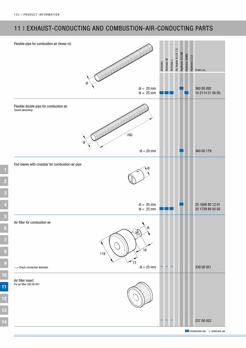
1
2
3
4
5
6
7
8
9
10
11
12
13
14
1 2 2 | P R O D u C T i n F O R M A T i O n
Airt
roni
c
Airt
roni
c M
Airt
roni
c L
Air
heat
er 8
L/V
7 S
Hydr
onic
4/5
kW
Hydr
onic
M/M
2
Hydr
onic
L/L
2
Order no.
unrestricted use ~ restricted use
11 | ExHAuST-COnDuCTing AnD COMbuSTiOn-AiR-COnDuCTing PARTS
Flexible pipe for combustion air (linear m)
di = 20 mm 360 00 092 di = 25 mm 10 2114 21 00 00
Flexible double pipe for combustion airSound-absorbing
di = 20 mm 360 00 179
End sleeve with crossbar for combustion-air pipe
di = 20 mm 25 1688 80 12 01 di = 25 mm 25 1729 89 00 02
Air filter for combustion air
di = 25 mm 330 00 051
Air filter insert For air filter 330 00 051
237 00 052~ ~ ~
~ ~ ~~ = Check connection diameter
di
di
760
didi
di
16
73
118

1
2
3
4
5
6
7
8
9
10
11
12
13
14
P R O D u C T i n F O R M A T i O n | 1 2 3
Airt
roni
c
Airt
roni
c M
Airt
roni
c L
Air
heat
er 8
L/V
7 S
Hydr
onic
4/5
kW
Hydr
onic
M/M
2
Hydr
onic
L/L
2
Order no.
unrestricted use ~ restricted use
11 | ExHAuST-COnDuCTing AnD COMbuSTiOn-AiR-COnDuCTing PARTS
Elbow for combustion airPlastic
di = 20 mm, h = 45 mm 22 1000 40 00 02 di = 25 mm, h = 50 mm 22 1000 40 00 01 Scoop with hose connection
d = 60 mm 22 1000 40 06 00
Silencer for combustion airFlexibleFor Hydronic S3, Hydronic 2 and Hydronic
Di = 20 mm, di = 38 mm, L1 = 180 mm, L = 780 mm 22 1000 40 00 13
Silencer for combustion airFlexible
di = 20 mm, L1 = 100 mm, L2 = 160 mm, L3 = 100 mm, L = 360 mm 22 1000 40 00 08 di = 25 mm, L1 = 135 mm, L2 = 405 mm, L3 = 25 mm, L = 565 mm 20 1689 80 05 00 di = 25 mm, L1 = 100 mm, L2 = 555 mm, L3 = 30 mm, L = 685 mm 25 1945 80 13 00
Flexible hose, see page 84
di
h
dd
di
L
L2
L3
L1
di
L
Di
L1

1
2
3
4
5
6
7
8
9
10
11
12
13
14
1 2 4 | P R O D u C T i n F O R M A T i O n
Airt
roni
c
Airt
roni
c M
Airt
roni
c L
Air
heat
er 8
L/V
7 S
Hydr
onic
4/5
kW
Hydr
onic
M/M
2
Hydr
onic
L/L
2
Order no.
unrestricted use ~ restricted use
12 | FASTEning PARTS
gEnERAL inFORMATiOn:
The fastening parts supplied take account of all standard installation conditions.
in installations in cars and buses, the heater or its mount can usually be rigidly attached to the corresponding part of the body.
However in trucks and in particular, construction machinery, rubber-metal buffers need to be installed as vibration dampers, but these must not be placed under tension or shearing stress.
This type of rubber-metal component also reduces structure-borne noise transmission and so they are used e.g. on houseboats for installing both the heater and the metering pump.
Please also refer to the safety information on this section in the heater documentation.

1
2
3
4
5
6
7
8
9
10
11
12
13
14
P R O D u C T i n F O R M A T i O n | 1 2 5
Airt
roni
c
Airt
roni
c M
Airt
roni
c L
Air
heat
er 8
L/V
7 S
Hydr
onic
4/5
kW
Hydr
onic
M/M
2
Hydr
onic
L/L
2
Order no.
unrestricted use ~ restricted use
12 | FASTEning PARTS
Hose clip
ø 16 – ø 25 mm 10 2067 01 60 25 ø 20 – ø 32 mm 10 2067 02 00 32 ø 32 – ø 50 mm 10 2067 03 20 50 ø 40 – ø 47 mm 15 2090 17 ø 50 – ø 70 mm 10 2067 05 00 70 ø 70 – ø 90 mm 10 2067 07 00 90 ø 90 – ø110 mm 10 2067 09 01 10
Hose clip with lug
ø 9 – ø 10.5 mm 152 61 104 ø 21 – ø 24.0 mm 152 61 115
Hose clip
ø 7 mm 10 2068 00 70 78 ø 9 mm 10 2068 00 90 98 ø 10 mm 10 2068 01 00 98 ø 11 mm 10 2068 01 10 98 ø 12 mm 10 2068 01 20 98 ø 14 mm 10 2068 01 40 98
Pipe clip for exhaust pipe
ø 26 – ø 28 mm 22 1000 51 44 00 ø 32 – ø 34 mm 22 1000 51 45 00
Pipe clip for exhaust pipe
ø 42 – ø 45 mm 152 09 004 ø 43 – ø 46 mm 152 09 005
~~ ~
~~
~~ ~ ~
~ ~ ~
~ ~ ~ ~ ~ ~~ ~ ~ ~ ~ ~~ ~ ~ ~ ~ ~~ ~ ~ ~ ~ ~~ ~ ~ ~ ~ ~~ ~ ~ ~ ~ ~ ~
~ ~ ~ ~ ~ ~~ ~
~ = Check connection diameter
~ = Check connection diameter
~ = Check connection diameter

1
2
3
4
5
6
7
8
9
10
11
12
13
14
1 2 6 | P R O D u C T i n F O R M A T i O n
Airt
roni
c
Airt
roni
c M
Airt
roni
c L
Air
heat
er 8
L/V
7 S
Hydr
onic
4/5
kW
Hydr
onic
M/M
2
Hydr
onic
L/L
2
Order no.
unrestricted use ~ restricted use
12 | FASTEning PARTS
Mounting bracket for metering pumpand Flowtronic Water Pump 800 S (see page 76)Rubber
Fuel, ø 34 mm 22 1000 50 03 00 Water, ø 41 mm 22 1000 50 07 00
Air hose fastening kit Plastic, 3 per pack
ø 60 – ø 100 mm 22 1000 50 02 00
Clipgalvanized
ø 28 mm 152 09 010 ø 41 mm 152 10 039 ø 50 mm 152 09 011Do not use for flexible exhaust pipes! ø 65 mm 152 09 012
ClipStainless steel
ø 25 mm 152 10 048 ø 28 mm 152 61 001 ø 32 mm 152 10 069
Pipe clip with rubber inlay
ø 10 mm 152 00 139 ø 41 mm 152 00 131
Fastening clip For water hoses, ø 15 mm – 20 mm
156 31 011➀
See page 130 for mounting bracket
~~
~ ~ ~ ~
~ ~ ~ ~ ~ ~
➀

1
2
3
4
5
6
7
8
9
10
11
12
13
14
P R O D u C T i n F O R M A T i O n | 1 2 7
Airt
roni
c
Airt
roni
c M
Airt
roni
c L
Air
heat
er 8
L/V
7 S
Hydr
onic
4/5
kW
Hydr
onic
M/M
2
Hydr
onic
L/L
2
Order no.
unrestricted use ~ restricted use
12 | FASTEning PARTS
Mounting bracket for metering pumpFor use with boats and camping vehicles
20 1634 80 06 00
Rubber spacer profile for exhaust line and water hosesSilicone rubber, temperature resistant
22 1000 50 10 02
gasket for exhaust pipe
di = 41 mm 20 8542 11 00 02
Mounting bracket for water pumpFor use with water pump 25 2217 27 00 00
(see page 76)
25 2217 27 01 00
21
20 44

1
2
3
4
5
6
7
8
9
10
11
12
13
14
1 2 8 | P R O D u C T i n F O R M A T i O n
Airt
roni
c
Airt
roni
c M
Airt
roni
c L
Air
heat
er 8
L/V
7 S
Hydr
onic
4/5
kW
Hydr
onic
M/M
2
Hydr
onic
L/L
2
Order no.
unrestricted use ~ restricted use
12 | FASTEning PARTS
gasket for heating-air duct
di = 72 – 85 mm, da = 100 mm 20 1280 04 00 01
Rubber grommet
di = 4 – 10 mm, da = 16.5 mm 20 1280 09 01 03
grommet for combustion-air pipe
di = 25 – 30 mm, da = 41 mm 20 1282 20 00 01
grommet for exhaust pipe
di = 23 – 30 mm, da = 41 mm 20 1549 65 00 02 di = 38 – 45 mm, da = 60 mm 20 1282 20 00 02

1
2
3
4
5
6
7
8
9
10
11
12
13
14
P R O D u C T i n F O R M A T i O n | 1 2 9
Airt
roni
c
Airt
roni
c M
Airt
roni
c L
Air
heat
er 8
L/V
7 S
Hydr
onic
4/5
kW
Hydr
onic
M/M
2
Hydr
onic
L/L
2
Order no.
unrestricted use ~ restricted use
12 | FASTEning PARTS
Rubber-metal buffer
thread size M6 / ST 6.3 C x 15 20 1673 80 01 01
Rubber-metal buffer
thread size 2 x M6 x 11 mm 20 1185 00 00 01
Rubber-metal bufferMetal-reinforced
thread size M6 x 10 mm / M6 x 15 mm 22 1000 50 00 08
Rubber-metal buffer
thread size 2 x M6 x 10, d = 20 mm, h1 = 15 mm, h2 = 35 mm 20 1607 65 00 02 thread size 2 x M6 x 10, d = 20 mm, h1 = 25 mm, h2 = 45 mm 20 1609 05 00 04 thread size 2 x M8 x 13, d = 30 mm, h1 = 15 mm, h2 = 41 mm 330 09 002

1
2
3
4
5
6
7
8
9
10
11
12
13
14
1 3 0 | P R O D u C T i n F O R M A T i O n
Airt
roni
c
Airt
roni
c M
Airt
roni
c L
Air
heat
er 8
L/V
7 S
Hydr
onic
4/5
kW
Hydr
onic
M/M
2
Hydr
onic
L/L
2
Order no.
unrestricted use ~ restricted use
12 | FASTEning PARTS
Mounting bracket
20 1348 03 00 02
Mounting bracket
20 1348 03 00 04
Mounting bracket
20 1533 88 00 07
L-mounting bracketFor exhaust silencer 22 1000 40 19 00
22 1000 51 34 00
z-mounting bracketFor exhaust silencer 22 1000 40 19 00
22 1000 51 35 00
See page 120 for exhaust silencer
See page 120 for exhaust silencer

1
2
3
4
5
6
7
8
9
10
11
12
13
14
P R O D u C T i n F O R M A T i O n | 1 3 1
Airt
roni
c
Airt
roni
c M
Airt
roni
c L
Air
heat
er 8
L/V
7 S
Hydr
onic
4/5
kW
Hydr
onic
M/M
2
Hydr
onic
L/L
2
Order no.
unrestricted use ~ restricted use
Mounting frame for EasyStart T
22 1000 51 33 00
EasyStart T – single part Fastening parts
22 1000 32 93 00
EasyStart T – single part bracket For slanting, level or convex installation surfaces
22 1000 51 32 00
Trim for EasyStart Timer
22 1000 51 41 00
Spacer plateRubber
6 mm thick 25 1482 89 00 02
unit mounting bracket
97° 20 1575 89 00 10 Stainless steel, 105° 22 1050 89 08 00
~ ~ ~ ~For use when replacing the modular timer with EasyStart T
12 | FASTEning PARTS
135
93103
83
140

1
2
3
4
5
6
7
8
9
10
11
12
13
14
1 3 2 | P R O D u C T i n F O R M A T i O n
Airt
roni
c
Airt
roni
c M
Airt
roni
c L
Air
heat
er 8
L/V
7 S
Hydr
onic
4/5
kW
Hydr
onic
M/M
2
Hydr
onic
L/L
2
Order no.
unrestricted use ~ restricted use
unit mounting bracket
24 0076 00 00 01
Heater mounting bracket
25 1482 89 00 11
unit mounting bracket
20 1575 89 04 00
Fastening plate
25 1482 89 00 13
Mounting bracket
22 1000 50 00 03
105140
120 140
110
170
55
85
130
40 42,5
140
224
260155
12 | FASTEning PARTS
45
10
160
135
10
75
45
200
60
35
125100

1
2
3
4
5
6
7
8
9
10
11
12
13
14
P R O D u C T i n F O R M A T i O n | 1 3 3
Airt
roni
c
Airt
roni
c M
Airt
roni
c L
Air
heat
er 8
L/V
7 S
Hydr
onic
4/5
kW
Hydr
onic
M/M
2
Hydr
onic
L/L
2
Order no.
unrestricted use ~ restricted use
12 | FASTEning PARTS
Mounting bracket
22 1000 50 00 06
Mounting bracket for Hydronic S3
22 1000 51 42 00
Mounting bracket for Hydronic
22 1000 51 36 00
Mounting bracket for Hydronic 2
22 1000 51 37 00
ø7 ( 8x )
200
135
4518
12014060
10
2714
87,5
➀
Also required:
M6x95 fastening screw, order no. 100 10 259
➀
➀
➀
Special screw also required:
for Economy / Comfort 25 2526 80 01 01
122
9511

1
2
3
4
5
6
7
8
9
10
11
12
13
14
1 3 4 | P R O D u C T i n F O R M A T i O n
Airt
roni
c
Airt
roni
c M
Airt
roni
c L
Air
heat
er 8
L/V
7 S
Hydr
onic
4/5
kW
Hydr
onic
M/M
2
Hydr
onic
L/L
2
Order no.
unrestricted use ~ restricted use
13 | nAME PLATES / inFORMATiOn SignS
name plates for heaters with a general design certification (german: Abg – Allgemeine bauartgenehmigung) are identifiable by the wavy line which is its mark of conformity ( ).
gEnERAL inFORMATiOn:
name plates
The name plate must be easily visible after installation. if necessary, a second (duplicate) name plate can be attached in a clearly visible place on the heater after installation or on one of the covers in front of the heater. A second plate is not required if the original can be seen by removing a cover without the aid of tools.
A second (duplicate) name plate can be sent on request (chargeable). To order this, complete the form below and fax it to the number given.
The duplicate name plate costs EuR 15.
name plates for heaters with an EC type approval are identifiable by the official EC and EEC type approval mark.
Please note!

1
2
3
4
5
6
7
8
9
10
11
12
13
14
P R O D u C T i n F O R M A T i O n | 1 3 5
Airt
roni
c
Airt
roni
c M
Airt
roni
c L
Air
heat
er 8
L/V
7 S
Hydr
onic
4/5
kW
Hydr
onic
M/M
2
Hydr
onic
L/L
2
Order no.
unrestricted use ~ restricted use
13 | nAME PLATES / inFORMATiOn SignS
ORDER2. nAME PLATE (DuPLiCATE)
Copy this form, fill in the information from the original identification label and fax your order to:
+49 (0)711 939 1130(germany only)
Heater type
Version
Version number
Factory number
Mark of conformity
or
EC type approval
and
EMC type approval
Fuel
Electrical values
Heat flow
Operating pressure
Company
Contact
Street, building number
zip code, town / city
VAT-no.
Phone
Fax
Sender (please print in block letters)
e1
e1

1
2
3
4
5
6
7
8
9
10
11
12
13
14
1 3 6 | P R O D u C T i n F O R M A T i O n
Airt
roni
c
Airt
roni
c M
Airt
roni
c L
Air
heat
er 8
L/V
7 S
Hydr
onic
4/5
kW
Hydr
onic
M/M
2
Hydr
onic
L/L
2
Order no.
unrestricted use ~ restricted use
13 | nAME PLATES / inFORMATiOn SignS
information sticker
25 2652 05 00 01
information sticker
25 1482 89 00 08

1
2
3
4
5
6
7
8
9
10
11
12
13
14
P R O D u C T i n F O R M A T i O n | 1 3 7
Airt
roni
c
Airt
roni
c M
Airt
roni
c L
Air
heat
er 8
L/V
7 S
Hydr
onic
4/5
kW
Hydr
onic
M/M
2
Hydr
onic
L/L
2
Order no.
unrestricted use ~ restricted use
14 | AuxiLiARy PRODuCTS – COnVECTORS
Airtr
onic
Airtr
onic
M
Airtr
onic
L
Air h
eate
r 8 L
/ V
7 S
Hydr
onic
Hydr
onic
M /
Hydr
onic
M-ii
Hydr
onic
L /
Hydr
onic
L-ii
Order no.
HELiOS 2000incl. on / off switch, airflow / h 125 m3, 2 kW
Aluminum grille 12 V 22 2282 10 41 00 L = 172, b = 129, T = 107 24 V 22 2282 10 42 00 Aluminum grille, gray 12 V 22 2282 10 41 20 L = 200, b = 170, T = 105 24 V 22 2282 10 42 20 Plastic grille, white 12 V 22 2282 10 41 21 L = 200, b = 170, T = 105 24 V 22 2282 10 42 21 Plastic grille, white 12 V 22 2282 10 41 22 L = 200, b = 170, T = 105 24 V 22 2282 10 42 22 Stainless steel grille 12 V 22 2282 10 41 09 L = 200, b = 170, T = 105 24 V 22 2282 10 42 09
HELiOS 2000 noiseless, incl. on / off switch, airflow / h 125 m3, 2 kW
Aluminum grille 12 V 22 2282 10 41 26 L = 172, b = 129, T = 107 24 V 22 2282 10 42 26
convectors and fan convectors with 2,000 – 10,000 W output.
~ ~ ~~ ~ ~~ ~ ~~ ~ ~~ ~ ~~ ~ ~~ ~ ~~ ~ ~~ ~ ~~ ~ ~
~ ~ ~~ ~ ~

1
2
3
4
5
6
7
8
9
10
11
12
13
14
1 3 8 | P R O D u C T i n F O R M A T i O n
Airt
roni
c
Airt
roni
c M
Airt
roni
c L
Air
heat
er 8
L/V
7 S
Hydr
onic
4/5
kW
Hydr
onic
M/M
2
Hydr
onic
L/L
2
Order no.
unrestricted use ~ restricted use
14 | AuxiLiARy PRODuCTS – COnVECTORS
HELiOS 2000 PREMiuMincl. on / off switch, airflow / h 125 m3, 2 kW
grille, black 12 V 22 2282 10 41 13 L = 172, b = 129, T = 103.5 24 V 22 2282 10 42 16 grille, white 12 V 22 2282 10 41 12 L = 172, b = 129, T = 103.5 24 V 22 2282 10 42 15 grille, gray 12 V 22 2282 10 41 11 L = 172, b = 129, T = 103.5 24 V 22 2282 10 42 11
HELiOS 2000 PREMiuMincl. on / off switch, airflow / h 125 m3, 2 kW
Aluminum grille 12 V 22 2282 10 41 14 L = 172, b = 129, T = 103.5 24 V 22 2282 10 42 17
HELiOS 4000incl. on / off switch, airflow / h: 250 m3, 4 kW
Aluminum grille 12 V 22 2282 10 51 00 L = 320, b = 129, T = 104 mm 24 V 22 2282 10 52 00
~ ~ ~
~ ~ ~~ ~ ~~ ~ ~~ ~ ~
~ ~ ~~ ~ ~
~ ~ ~~ ~ ~

1
2
3
4
5
6
7
8
9
10
11
12
13
14
P R O D u C T i n F O R M A T i O n | 1 3 9
Airt
roni
c
Airt
roni
c M
Airt
roni
c L
Air
heat
er 8
L/V
7 S
Hydr
onic
4/5
kW
Hydr
onic
M/M
2
Hydr
onic
L/L
2
Order no.
unrestricted use ~ restricted use
14 | AuxiLiARy PRODuCTS – COnVECTORS
HELiOS 7000With housing and on / off switch, airflow / h 500 m3, 4 kW
12 V 22 2282 10 61 00 L = 580, b = 129, T = 140 mm 24 V 22 2282 10 62 00
HELiOS 7000Without housing, with on / off switch, airflow / h 500 m3, 4 kW
12 V 22 2282 10 61 03 L = 580, b = 129, T = 124 mm 24 V 22 2282 10 62 03
xEROS 4000Airflow / h 200 m3, 4 kW
Standard 12 V 22 2282 11 01 00 L = 273, b = 114, T = 207 mm 24 V 22 2282 11 02 00 Plastic grille 12 V 22 2282 11 01 10 L = 273, b = 114, T = 207 mm 24 V 22 2282 11 02 10 Plastic grille, front and side 12 V 22 2282 11 01 11 L = 273, b = 114, T = 207 mm 24 V 22 2282 11 02 11 Marine stainless steel plate 12 V 22 2282 11 01 31 L = 273, b = 114, T = 207 mm 24 V 22 2282 11 02 31 ø 14, L = 258, b = 115, T = 200 mm 12 V 22 2282 11 01 02
~ ~ ~~ ~ ~~ ~ ~~ ~ ~~ ~ ~~ ~ ~~ ~ ~~ ~ ~~ ~ ~
~ ~~ ~
~ ~~ ~
T
L��
B
TL��
B��
T
L��
B

1
2
3
4
5
6
7
8
9
10
11
12
13
14
1 4 0 | P R O D u C T i n F O R M A T i O n
Airt
roni
c
Airt
roni
c M
Airt
roni
c L
Air
heat
er 8
L/V
7 S
Hydr
onic
4/5
kW
Hydr
onic
M/M
2
Hydr
onic
L/L
2
Order no.
unrestricted use ~ restricted use
14 | AuxiLiARy PRODuCTS – COnVECTORS
xEROS 4000with fittings, airflow / h: 200 m3, 4 kW
with 2 fittings, ø 45 12 V 22 2282 11 01 66 L = 273, b = 114, T = 207 mm 24 V 22 2282 11 02 66 with 2 fittings, ø 50 12 V 22 2282 11 01 61 L = 273, b = 114, T = 207 mm 24 V 22 2282 11 02 61 with 2 fittings, ø 60 12 V 22 2282 11 01 63 L = 273, b = 114, T = 207 mm 24 V 22 2282 11 02 63 with 2 fittings, ø 75 12 V 22 2282 11 01 65 L = 273, b = 114, T = 207 mm 24 V 22 2282 11 02 65 with rotatable and closable vents L = 273, b = 114, T = 207 mm 12 V 22 2282 11 01 53
zEniTH 8000Airflow / h: 440 m3, 8 kW
Standard 12 V 22 2282 11 21 00 L = 315, b = 130, T = 242 mm 24 V 22 2282 11 22 00 with plastic grilles 12 V 22 2282 11 21 03 L = 315, b = 130, T = 242 mm 24 V 22 2282 11 22 03 with 3 fittings ø 60 12 V 22 2282 11 21 01 L = 315, b = 130, T = 242 mm 24 V 22 2282 11 22 01 with 3 fittings ø 75 12 V 22 2282 11 21 02 L = 315, b = 130, T = 242 mm 24 V 22 2282 11 22 02 with 4 fittings ø 60 12 V 22 2282 11 21 04 L = 315, b = 130, T = 242 mm 24 V 22 2282 11 22 04
ARTik 10 000Airflow / h: 440 m3, 10 kW
Marine stainless steel defroster 12 V 22 2282 11 31 00C L = 442, b = 132, T = 225 24 V 22 2282 11 32 00C
~ ~ ~~ ~ ~~ ~ ~~ ~ ~~ ~ ~~ ~ ~~ ~ ~~ ~ ~
~ ~ ~
~ ~ ~~ ~ ~~ ~ ~~ ~ ~~ ~ ~~ ~ ~~ ~ ~~ ~ ~~ ~ ~~ ~ ~
~ ~ ~~ ~ ~
B
LT
TL��
B
D

1
2
3
4
5
6
7
8
9
10
11
12
13
14
P R O D u C T i n F O R M A T i O n | 1 4 1
Airt
roni
c
Airt
roni
c M
Airt
roni
c L
Air
heat
er 8
L/V
7 S
Hydr
onic
4/5
kW
Hydr
onic
M/M
2
Hydr
onic
L/L
2
Order no.
unrestricted use ~ restricted use
14 | AuxiLiARy PRODuCTS – COnVECTORS
~ ~ ~
accessories
grille for HELiOS 2000 convector
Aluminum 22 2134 08 60 00C L = 170, b = 140
Stainless steel 22 2134 09 90 00b L = 170, b = 140
grille for HELiOS 2000 convector
Plastic, black 22 2134 10 10 01 L = 200, b = 170, T = 22
Plastic, white 22 2134 10 10 02 L = 200, b = 170, T = 22
Plastic, gray 22 2134 10 10 00 L = 200, b = 170, T = 22
Plastic grille for zEniTH 8000 convector
22 2145 73 50 00A
Plastic air diffuser with 3 fittings, for zEniTH 8000 convector
ø 60 mm 22 2145 73 40 00A L = 231, b = 131, T = 6
~ ~ ~
~ ~ ~
~ ~ ~
~ ~ ~
~ ~ ~
~ ~ ~
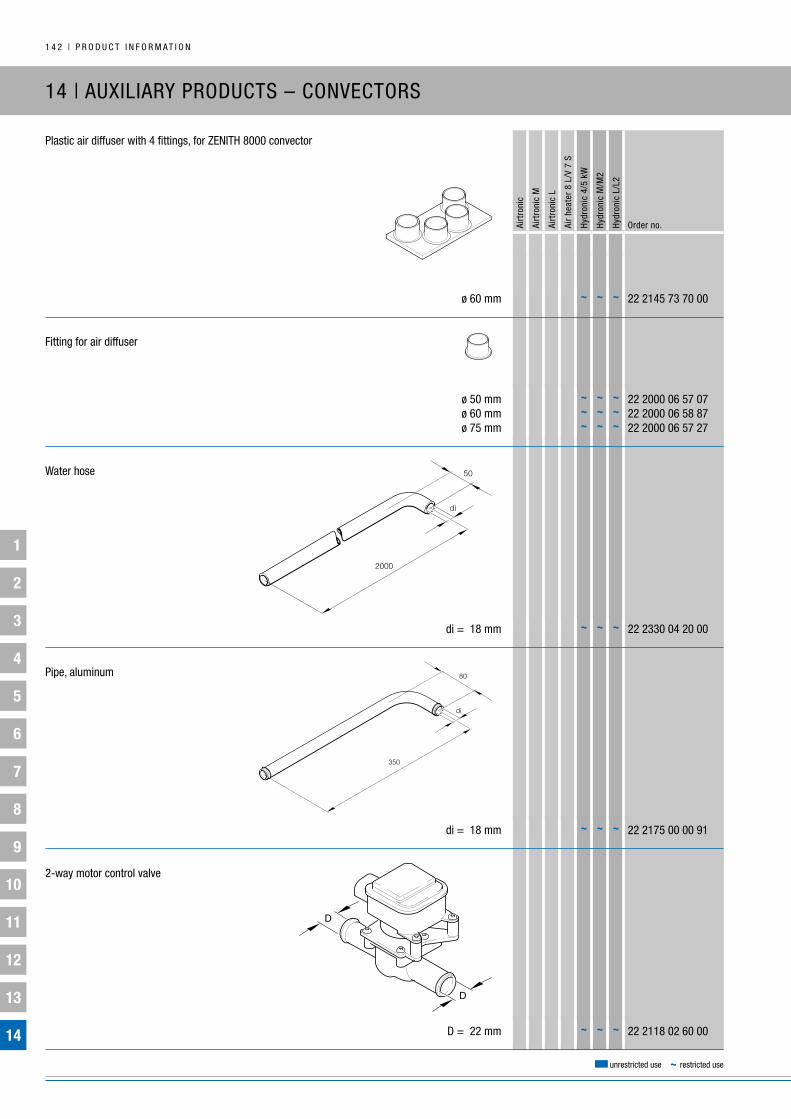
1
2
3
4
5
6
7
8
9
10
11
12
13
14
1 4 2 | P R O D u C T i n F O R M A T i O n
Airt
roni
c
Airt
roni
c M
Airt
roni
c L
Air
heat
er 8
L/V
7 S
Hydr
onic
4/5
kW
Hydr
onic
M/M
2
Hydr
onic
L/L
2
Order no.
unrestricted use ~ restricted use
14 | AuxiLiARy PRODuCTS – COnVECTORS
Plastic air diffuser with 4 fittings, for zEniTH 8000 convector
ø 60 mm 22 2145 73 70 00
Fitting for air diffuser
ø 50 mm 22 2000 06 57 07 ø 60 mm 22 2000 06 58 87 ø 75 mm 22 2000 06 57 27
Water hose
di = 18 mm 22 2330 04 20 00
Pipe, aluminum
di = 18 mm 22 2175 00 00 91
2-way motor control valve
D = 22 mm 22 2118 02 60 00~ ~ ~
~ ~ ~
~ ~ ~
~ ~ ~
~ ~ ~~ ~ ~~ ~ ~

1
2
3
4
5
6
7
8
9
10
11
12
13
14
P R O D u C T i n F O R M A T i O n | 1 4 3
Airt
roni
c
Airt
roni
c M
Airt
roni
c L
Air
heat
er 8
L/V
7 S
Hydr
onic
4/5
kW
Hydr
onic
M/M
2
Hydr
onic
L/L
2
Order no.
unrestricted use ~ restricted use
14 | AuxiLiARy PRODuCTS – inDiViDuAL DEViCES
Warm water boiler
10 l, upright, single coil 17700 L = 390 mm, d = 250 mm
10 l, horizontal, single coil 17722 L = 550 mm, d = 250 mm
22 l, horizontal, single coil * 17794 L = 510 mm, d = 370 mm
22 l, horizontal, double coil * 17795 L = 510 mm, d = 370 mm
30 l, horizontal, single coil * 17796 L = 610 mm, d = 370 mm
30 l, horizontal, double coil * 17797 L = 610 mm, d = 370 mm
40 l, horizontal, single coil * 17798 L = 750 mm, d = 370 mm
40 l, horizontal, double coil * 17799 L = 750 mm, d = 370 mm
55 l, horizontal, single coil * 17800 L = 970 mm, d = 370 mm
55 l, horizontal, double coil * 17801 L = 970 mm, d = 370 mm
75 l, horizontal, single coil * 17802 L = 1130 mm, d = 400 mm
75 l, horizontal, double coil * 17803 L = 1130 mm, d = 400 mm
All warm water boilers have an integrated 220 V – 240 V AC heating coil.
* Thermostatic mixing valve
Supplier:Eberspächer (uk) Ltd.Headlands business ParkSalisbury Road, RingwoodHampshire bH24 3Pb, ukTel. + 44 14 25 48 01 51Fax. + 44 14 25 48 01 52
~ ~ ~
~ ~ ~
~ ~ ~
~ ~ ~
~ ~ ~
~ ~ ~
~ ~ ~
~ ~ ~
~ ~ ~
~ ~ ~
~ ~ ~
~ ~ ~
gEnERAL inFORMATiOn On THiRD-PARTy PRODuCTS:
not all auxiliary products can be purchased direct from Eberspächer. Where applicable, these products must be ordered from the specified supplier.

1
2
3
4
5
6
7
8
9
10
11
12
13
14
1 4 4 | P R O D u C T i n F O R M A T i O n
Airt
roni
c
Airt
roni
c M
Airt
roni
c L
Air
heat
er 8
L/V
7 S
Hydr
onic
4/5
kW
Hydr
onic
M/M
2
Hydr
onic
L/L
2
Order no.
unrestricted use ~ restricted use
14 | AuxiLiARy PRODuCTS – inDiViDuAL DEViCES
Stainless steel box for Airtronic D2 / D4
b = 147 mm, H = 212 mm, T = 295 mm on request b = 172 mm, H = 240 mm, T = 360 mm from manufacturer
Polarn 4000Portable, diesel-operated heater with Airtronic D4 – compact air heater with integrated 5 l diesel tank
12 V / 220 V 24 9988 00 00 21 12 V 24 9988 00 00 10 24 V 24 9988 00 00 22
POLARn 8000Portable, diesel-operated heater with air heater 8L – compact air heater with fuel supply from separate tank
12 V 24 9988 00 00 32 24 V 24 9988 00 00 33
Supplier:kjöller Eberspächer MarineRovsingsgade 82Copenhagen n, Dk – 2000, DenmarkTel. + 45 35 82 95 00Fax. + 45 35 82 50 95
W
D
H

1
2
3
4
5
6
7
8
9
10
11
12
13
14
P R O D u C T i n F O R M A T i O n | 1 4 5
Airt
roni
c
Airt
roni
c M
Airt
roni
c L
Air
heat
er 8
L/V
7 S
Hydr
onic
4/5
kW
Hydr
onic
M/M
2
Hydr
onic
L/L
2
Order no.
unrestricted use ~ restricted use
14 | AuxiLiARy PRODuCTS – inDiViDuAL DEViCES
Marine kit – air heater
Airtronic D2 – 12 V 24 8997 00 00 00 Marine kit
Airtronic D4 – 12 V 24 8998 00 00 00 Marine kit
Airtronic D5 – 12 V 24 8999 00 00 00 Marine kit
Marine kit – water heater
Product package:
▪ Control unit (mini-controller) ▪ Mounting bracket for heater ▪ Cable harness ▪ Combustion-air intake silencer ▪ Exhaust pipe angle ▪ Exhaust silencer ▪ Hull fitting ▪ Fuel tank extractor ▪ Fuel pipes ▪ Fuel hoses ▪ Temperature sensor ▪ Various mounting brackets ▪ Mounting accessories
To be ordered separately: all air ducts for the planned heating-air ducting
Optional:EasyStart Timer timer switch (see page 100)
Product package:
▪ Mounting bracket for heater ▪ Cable harness ▪ Combustion-air intake silencer ▪ Exhaust silencer ▪ Hull fitting ▪ Fuel tank extractor ▪ Fuel pipes ▪ Fuel hose ▪ Fastening parts ▪ Electrical parts ▪ Water hoses ▪ Connection parts ▪ Mounting accessories
To be ordered separately:EasyStart Timer timer switch (see page 100)
Hydronic D 5 WS – 12 V 24 8992 00 00 00 Marine kit
Hydronic D 5 WS – 24 V 24 8991 00 00 00 Marine kit
Hydronic M / M-ii – 12 / 24 V 24 8993 00 00 00 Marine kit

8670
191
· Ver
sion
06/
2017
· FA
CT |
fact
net.d
ePr
inte
d in
ger
man
y. S
ubje
ct to
cha
nge
with
out n
otic
e.
MORE inFORMATiOn iS AVAiLAbLE FROM Any OF OuR 5,000 SERViCE PARTnERS
WORLDWiDE.
Eberspächer Climate Control Systems gmbH & Co. kg
Eberspächerstrasse 24
73730 Esslingen
gERMAny
Phone: +49 711 939 00
Fax: +49 711 939 0634
www.eberspaecher.com
gERMAny
Eberspächer Heizung
Vertriebs-gmbH & Co. kg
Wilhelmstrasse 47
17358 Torgelow
Hotline: +49 800 1234300
Fax hotline: +49 1805 262624
www.eberspaecher-standheizung.com
AuSTRiA
Eberspächer gmbH
iz nÖ-Süd2
Hondastraße 2, Obj. M47
2351 Wiener neudorf
Phone: +43 (0)2236 6771440
Fax: +43 (0)2236 67714442
www.eberspaecher.at