Embed Size (px)
Citation preview
NI AUTOMOTIVE JOURNAL
TEST THE VEHICLES OF TOMORROW TODAY A NATIONAL INSTRUMENTS PUBLICATION Q1 + 2020
VEHICLE ARCHITECTURE TRENDS // BODY AND CHASSIS TESTING INNOVATIONS // CASE STUDIES
US Corporate Headquarters11500 N Mopac Expwy, Austin, TX 78759-3504T: 512 683 0100 F: 512 683 9300 [email protected]
ni.com/global–International Branch Officesni.com/automotive
Testing the Vehicle Electronics of Tomorrow TodayAs we close on the first quarter of 2020, the total impact of COVID-19 has yet to be determined. Automotive leaders are not waiting to find out. As new vehicle demand drops, automotive leaders like GM, Ford, Jaguar Land Rover, and others are partnering to utilize manufacturing capacity to produce much-needed medical equipment. Just like the envisioned future of mobility, these actions are to further our collective society, overcome challenges together, and improve the quality of life around the world.
This crisis will pass, and focus will shift back to vehicle programs that were delayed or repurposed. In prior Journal issues we have put a spotlight on connected, electric, and autonomous vehicles. The impact of these technologies will impact the full vehicle, even technology domains that we might consider “traditional.” As an example, the test teams working on body and chassis components are feeling the effects of new NVH test requirements for super-quiet EVs. Once-simple controllers now need to interface with a central gateway ECU. New EV architectures requires each component to communicate for permission to access power.
Let’s celebrate the teams working on the intersection of new technology and time-tested platforms. The tests done within the body and chassis domain of the car add a layer of complexity with physical tests such as durability testing. This is in addition to the growth in complexity brought on by automotive electronics and software-based subsystems. NI has been enabling these test engineers with a broad portfolio of I/O and processor capabilities. Along with our partner ecosystem, we have the capability to provide complete test solutions for vehicle components and vehicle-level integration test.
Chad Chesney, Vice President and General Manager, Transportation Business
New ECU Test System
IN THIS
ISSUEQ1 + 2020
Let’s explore how the explosion of electrical systems in vehicles has fundamentally changed body and chassis systems, and how test methodologies need to adapt to test these increasingly complex and connected components.
9Full Test Coverage: CompactRIO with DAQmx
14Electric Parking Brake HIL and Durability Testing Reduces Time-to-Market
16Body ECU HIL Test Solution
22End-of-Line NVH Test Solution
24Selecting an Approach to Build Flexible, Cost-Effective ECU Production Test Systems
28Fully Automated, Dynamic Steering Test Bench Minimized Test Runs
5 HIL Trends for Chassis & Body Electronics Test
1812Vehicle Systems Integration HIL
30
©2020 National Instruments. All rights reserved. CompactRIO, LabVIEW, Multisim, National Instruments, NI, ni.com, NI FlexRIO, NI TestStand, NI VeriStand, and NIWeek are trademarks of National Instruments. Other product and company names listed are trademarks or trade names of their respective companies. A National Instruments Alliance Partner is a business entity independent from National Instruments and has no agency, partnership, or joint-venture relationship with National Instruments. 36061
ni.com/automotive | 3
Reinventing Everything but the WheelThe automotive industry is changing rapidly; you don’t have to scroll far through headlines to find something about how the future of mobility is being shaped. These headlines often fail to capture that these developments are not occurring in isolation, but are multiple and concurrent technological innovations maturing simultaneously. Creating an autonomous vehicle isn’t just a matter of installing an “autonomy
package” on the latest vehicle off the line. Making an EV isn’t as easy as swapping out your combustion engine for a battery, motor, and inverter.
These technologies are so radically different they require a fundamental shift in what the vehicle itself is, and almost no component is left untouched in this shift. A side view mirror no longer just reflects light, it now has a
camera and radar sensor, and its own ECU, along with a vehicle electronics architecture and networking technology that supports it efficiently, exchanging data with the rest of the car. Here, we will explore autonomous driving, connected vehicles, electrification of the powertrain, and shared mobility have changed not just the composition of core components of the vehicle but the automotive value chain itself.
FEATURED ARTICLE
Electronics Architecture EvolutionAs vehicles become increasingly connected, automated, and electrified, the number of ECUs has exploded to 150 per vehicle. This proliferation in controllers has stressed existing architectures by requiring more:
■ Complexity and computing power to handle sophisticated functions■ Scalability and flexibility of components to handle variants and easily introduce new innovations■ Communication bandwidth as data traffic within and between domains increases■ External communication for interacting with an increasingly intelligent environment
4 | Q1 + 2020
Distributed Domain Centralized Vehicle Centralized
Today
Central Gateway
Isolated- Independent function
specific ECUs
Integrated- Central gateway
connects ECUs across domains
- Begin consolidation of several simple ECUs into single performance ECU
Modular- Domain networks form- Domains still largely
independent
ChassisInfo-
tainmentBody/
Comfort
Powertrain
Central Gateway
Domain Controller
Domain Fusion- Cost optimization
through consolidation- Central controller
per domain- Fusion of like
domains and functions- Standardization
of networks
Vehicle Fusion- Mechatronic rim
of zone ECUs- Central vehicle
computation unit- Virtual domain
activated based on software function called
Vehicle Cloud Computing- Non safety critical
functions transferred to the cloud
Powertrain Powertrain
Vehicle Computation
Unit
Zone 2Zone 1Sensor
Actuator
Vehicle Computation Unit Cloud
4 | Q1 + 2020
FEATURED ARTICLE
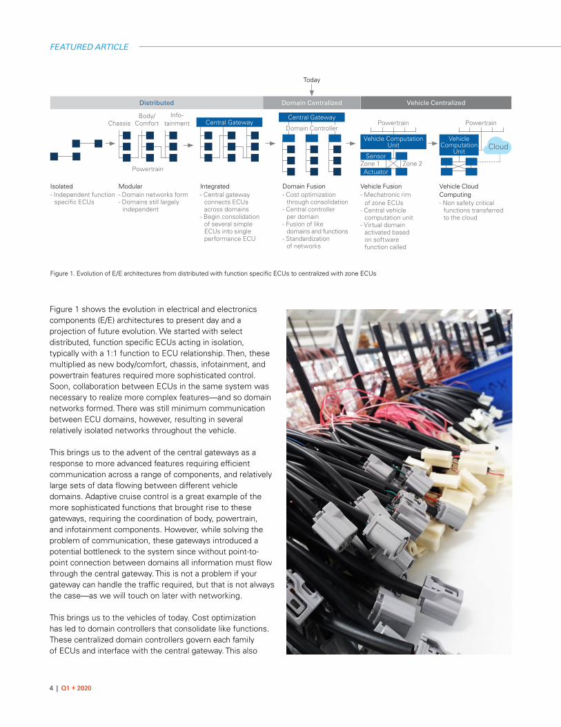
Figure 1 shows the evolution in electrical and electronics components (E/E) architectures to present day and a projection of future evolution. We started with select distributed, function specific ECUs acting in isolation, typically with a 1:1 function to ECU relationship. Then, these multiplied as new body/comfort, chassis, infotainment, and powertrain features required more sophisticated control. Soon, collaboration between ECUs in the same system was necessary to realize more complex features—and so domain networks formed. There was still minimum communication between ECU domains, however, resulting in several relatively isolated networks throughout the vehicle.
This brings us to the advent of the central gateways as a response to more advanced features requiring efficient communication across a range of components, and relatively large sets of data flowing between different vehicle domains. Adaptive cruise control is a great example of the more sophisticated functions that brought rise to these gateways, requiring the coordination of body, powertrain, and infotainment components. However, while solving the problem of communication, these gateways introduced a potential bottleneck to the system since without point-to-point connection between domains all information must flow through the central gateway. This is not a problem if your gateway can handle the traffic required, but that is not always the case—as we will touch on later with networking.
This brings us to the vehicles of today. Cost optimization has led to domain controllers that consolidate like functions. These centralized domain controllers govern each family of ECUs and interface with the central gateway. This also
Figure 1. Evolution of E/E architectures from distributed with function specific ECUs to centralized with zone ECUs
Experts in Automotive Testing
www.measx.com
Solution for Analysis and Reporting Tasks
Software for Driving Dynamics Testing
Analysis Systems forVehicle Safety Tests
Get the Solution That Moves You Foreward!
x Test Data Management and Analysis Systems
x Test Bench Technology and Automation
x In-Vehicle Test Systems
ni.com/automotive | 5
alleviates some of the bottleneck, as not everything needs to flow through the central gateway.
We expect future architecture iterations to feature increased abstraction of software functionality from hardware. Fixed function hardware separated by vehicle domain will be replaced by a network of distributed sensors and actuators throughout the vehicle that make up a “mechatronic rim.” Components will be grouped by zone instead of domain, and managed by a central vehicle computation unit that serves as the vehicle’s brain, with all the processing happening in these centralized controllers. This central unit then activates a virtual domain of zone ECUs based on the function that was called. As performance and subsequently required computing power increase—as we have not only intelligent vehicles but intelligent
environments for them to interact with—we may see non-safety critical functions migrated to the cloud.
This evolution of E/E architectures from function-based ECUs to domain-based to server- or cloud-based is the only way vehicles can manage the complexity the future of mobility requires.
Sophistication is in the Software We expect an increasing separation between ECU hardware and the software that runs on it to support future server-based virtual domain E/E architectures. ECU hardware will become more standardized and commoditized, especially in the mechatronic rim, abstracted from the software that runs on it, to deliver differentiation. This abstraction would enable flexibility—like the ability to selectively turn various driver
assistance features on or off, and simplify the process of pushing updates to the vehicle. With a zonal architecture, manufacturers can consolidate all their software functions and IP into the single central vehicle computation unit.
However, it is important to note that this is not a one-size-fits-all approach and there is not one archetype of the “future vehicle of tomorrow.” In ten years we expect internal combustion cars to still be in production and a range of autonomy and luxury levels to be present. The abstraction of the software from the hardware enables this variation to some extent, as the same hardware components can be used in a robotaxi, luxury electric vehicle, and internal combustion budget car but serve a very different purpose in each. Regardless, we expect each to be increasingly software defined as we move forward.
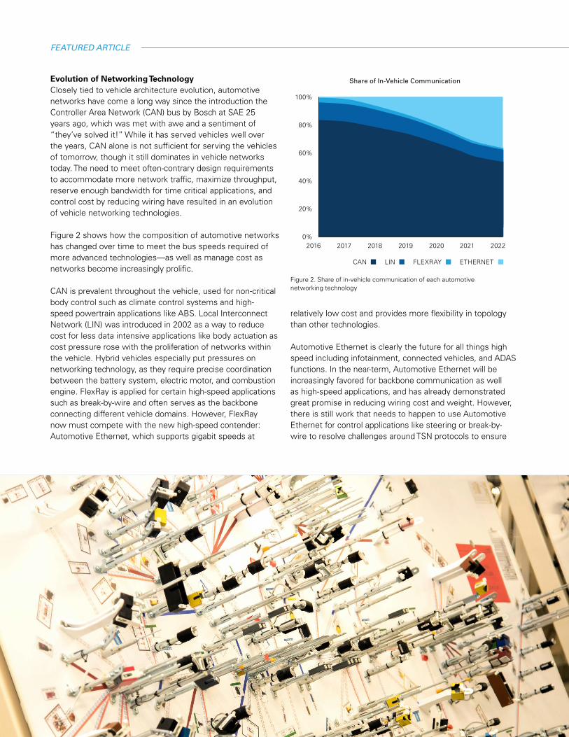
Share of In-Vehicle Communication
100%
80%
60%
40%
20%
0%2016 2018 20212017 20202019 2022
ETHERNETFLEXRAYLINCAN
Figure 2. Share of in-vehicle communication of each automotive networking technology
FEATURED ARTICLE
Evolution of Networking TechnologyClosely tied to vehicle architecture evolution, automotive networks have come a long way since the introduction the Controller Area Network (CAN) bus by Bosch at SAE 25 years ago, which was met with awe and a sentiment of “they’ve solved it!” While it has served vehicles well over the years, CAN alone is not sufficient for serving the vehicles of tomorrow, though it still dominates in vehicle networks today. The need to meet often-contrary design requirements to accommodate more network traffic, maximize throughput, reserve enough bandwidth for time critical applications, and control cost by reducing wiring have resulted in an evolution of vehicle networking technologies.
Figure 2 shows how the composition of automotive networks has changed over time to meet the bus speeds required of more advanced technologies—as well as manage cost as networks become increasingly prolific.
CAN is prevalent throughout the vehicle, used for non-critical body control such as climate control systems and high-speed powertrain applications like ABS. Local Interconnect Network (LIN) was introduced in 2002 as a way to reduce cost for less data intensive applications like body actuation as cost pressure rose with the proliferation of networks within the vehicle. Hybrid vehicles especially put pressures on networking technology, as they require precise coordination between the battery system, electric motor, and combustion engine. FlexRay is applied for certain high-speed applications such as break-by-wire and often serves as the backbone connecting different vehicle domains. However, FlexRay now must compete with the new high-speed contender: Automotive Ethernet, which supports gigabit speeds at
relatively low cost and provides more flexibility in topology than other technologies.
Automotive Ethernet is clearly the future for all things high speed including infotainment, connected vehicles, and ADAS functions. In the near-term, Automotive Ethernet will be increasingly favored for backbone communication as well as high-speed applications, and has already demonstrated great promise in reducing wiring cost and weight. However, there is still work that needs to happen to use Automotive Ethernet for control applications like steering or break-by-wire to resolve challenges around TSN protocols to ensure
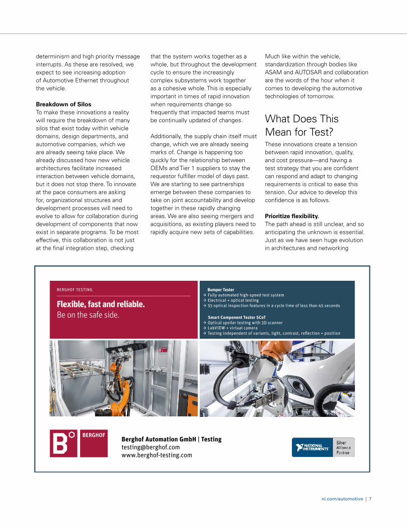
BERGHOF TESTING Flexible, fast and reliable. Be on the safe side.
Bumper Tester
→ Fully automated high-speed test system → Electrical + optical testing → 55 optical inspection features in a cycle time of less than 45 seconds
Smart Component Tester SCoT → Optical spoiler testing with 3D scanner → LabVIEW + virtual camera → Testing independent of variants, light, contrast, reflection + position
Berghof Automation GmbH | Testing [email protected]
ni.com/automotive | 7
determinism and high priority message interrupts. As these are resolved, we expect to see increasing adoption of Automotive Ethernet throughout the vehicle.
Breakdown of SilosTo make these innovations a reality will require the breakdown of many silos that exist today within vehicle domains, design departments, and automotive companies, which we are already seeing take place. We already discussed how new vehicle architectures facilitate increased interaction between vehicle domains, but it does not stop there. To innovate at the pace consumers are asking for, organizational structures and development processes will need to evolve to allow for collaboration during development of components that now exist in separate programs. To be most effective, this collaboration is not just at the final integration step, checking
that the system works together as a whole, but throughout the development cycle to ensure the increasingly complex subsystems work together as a cohesive whole. This is especially important in times of rapid innovation when requirements change so frequently that impacted teams must be continually updated of changes.
Additionally, the supply chain itself must change, which we are already seeing marks of. Change is happening too quickly for the relationship between OEMs and Tier 1 suppliers to stay the requestor fulfiller model of days past. We are starting to see partnerships emerge between these companies to take on joint accountability and develop together in these rapidly changing areas. We are also seeing mergers and acquisitions, as existing players need to rapidly acquire new sets of capabilities.
Much like within the vehicle, standardization through bodies like ASAM and AUTOSAR and collaboration are the words of the hour when it comes to developing the automotive technologies of tomorrow.
What Does This Mean for Test?These innovations create a tension between rapid innovation, quality, and cost pressure—and having a test strategy that you are confident can respond and adapt to changing requirements is critical to ease this tension. Our advice to develop this confidence is as follows.
Prioritize flexibility.The path ahead is still unclear, and so anticipating the unknown is essential. Just as we have seen huge evolution in architectures and networking
technology to get us to today, we do not know what will get us to tomorrow.
To answer this, we see our customers prioritize investments that allow for flexibility. This may look like choosing a test platform with flexibility in I/O to accommodate new signal types as features are added in, or maintaining ownership of their test architecture so that they have the capability to iterate rapidly in-house without starting from scratch again with a test vendor. The growth in popularity of the modular PXI platform over traditional box instrumentation is one example of this.
Software testing is only going to get more challenging.With increased abstraction and commoditization of hardware components, the ability to develop and test software-defined and interconnected systems will be an increasing requirement for success. As these software functions become more sophisticated, traditional tools and process may not keep up.
We have already seen large shifts in investment by Tier 1 suppliers and OEMs to hire software engineers, investigate methodologies like hardware-in-the-loop testing with NI VeriStand which save essential time in the development process, or adopt tools that increase efficiency in validation or production like NI TestStand for test automation.
Collaboration is essential.The ability to translate test data and methodologies across domains and even companies is increasingly important as we see the lines blur between vehicle domains and increased partnership between OEMs and Tier 1 Suppliers.
To effectively collaborate in these new partnerships, choose tools such as NI SystemLink that surface data in easily relatable ways and standardize on hardware and software that is applicable across DUTs and throughout the design cycle.
NI provides powerful, flexible, and collaborative tools for testing automotive hardware and software. However, we also realize that the challenges facing the automotive industry are too complex for any one test vendor to solve alone. This is why our tools are purpose built around openness, and we have partnered with industry leaders like ETAS, MathWorks, and Amazon to help you build a test strategy you feel confident can answer tomorrow's challenges.
The automotive industry may not have reinvented the wheel itself just yet, but it is clear that to get to the connected, electrified, autonomous vehicles of tomorrow we might have to fall just short of that and are already well on the path to doing so. Is your test strategy ready?
Selene van der Walt, NI Body & Chassis Test Lead
FEATURED ARTICLE
ni.com/automotive | 9
PRODUCT FOCUS
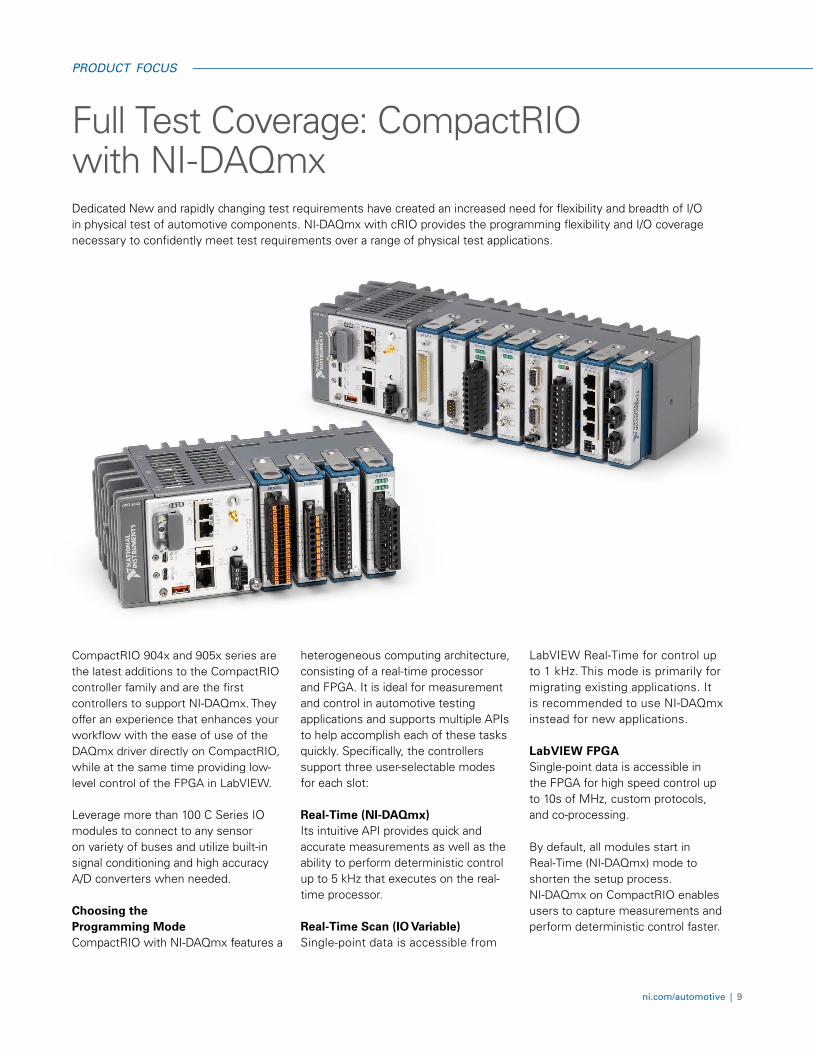
CompactRIO 904x and 905x series are the latest additions to the CompactRIO controller family and are the first controllers to support NI-DAQmx. They offer an experience that enhances your workflow with the ease of use of the DAQmx driver directly on CompactRIO, while at the same time providing low-level control of the FPGA in LabVIEW.
Leverage more than 100 C Series IO modules to connect to any sensor on variety of buses and utilize built-in signal conditioning and high accuracy A/D converters when needed. Choosing the Programming Mode CompactRIO with NI-DAQmx features a
heterogeneous computing architecture, consisting of a real-time processor and FPGA. It is ideal for measurement and control in automotive testing applications and supports multiple APIs to help accomplish each of these tasks quickly. Specifically, the controllers support three user-selectable modes for each slot: Real-Time (NI-DAQmx) Its intuitive API provides quick and accurate measurements as well as the ability to perform deterministic control up to 5 kHz that executes on the real-time processor. Real-Time Scan (IO Variable) Single-point data is accessible from
LabVIEW Real-Time for control up to 1 kHz. This mode is primarily for migrating existing applications. It is recommended to use NI-DAQmx instead for new applications. LabVIEW FPGA Single-point data is accessible in the FPGA for high speed control up to 10s of MHz, custom protocols, and co-processing.
By default, all modules start in Real-Time (NI-DAQmx) mode to shorten the setup process. NI-DAQmx on CompactRIO enables users to capture measurements and perform deterministic control faster.
Full Test Coverage: CompactRIO with NI-DAQmxDedicated New and rapidly changing test requirements have created an increased need for flexibility and breadth of I/O in physical test of automotive components. NI-DAQmx with cRIO provides the programming flexibility and I/O coverage necessary to confidently meet test requirements over a range of physical test applications.

Table 1. Select C series I/O modules
10 | Q1 + 2020
PRODUCT FOCUS
Accomplish More with NI-DAQmx on CompactRIO Beyond supporting NI-DAQmx on CompactRIO, the driver has also improved to allow for more customization and control. The new controllers provide a hardware timing engine per slot to allow for better customization with multi-rate applications. They also support deterministic control up to 5 kHz (904x) and 2.5 kHz (905x) with the addition of support for Hardware-Timed Single-Point.
By using hardware-timed single-point, samples are acquired or generated continuously utilizing hardware timing and no buffer.
This helps enforce the strict timing requirements often needed in control applications. Survive Industrial Environments with Rugged Packaging The CompactRIO Controller delivers unrivaled control and acquisition capabilities in a compact, rugged package and features an operating
temperature range of up to -40 °C to 70 °C (-40 °F to 158 °F); 50 g shock and 5 g vibration ratings; redundant power supply inputs; and a variety of international safety, Hazloc, and environmental certifications and ratings for operation in harsh industrial environments.
Leverage a Vast Ecosystem and Improve Security with NI Linux Real-Time Harness the openness of NI Linux Real-Time through thousands of open-source applications, IP, and examples while collaborating with an active community of users and developers. National Instruments developed the Linux-based real-time OS (RTOS) through years of R&D development and collaboration with the Real-Time Linux project. Use OPKG package manager to install, manage, and make use of the ecosystem online.
Boost security and reliability with native support for Security-Enhanced Linux. Security-Enhanced Linux (SELinux) is a mandatory access control (MAC) based system that uses a security policy to
explicitly specify the actions that each component of the system can perform.
Connect to the Outside World Connect components directly to your CompactRIO Controller with built-in processor I/O such as Gigabit Ethernet, serial, and USB ports. Pick from more than 100 I/O modules with measurement-specific signal conditioning to meet your applications requirements.
Connect directly to industrial cameras for custom image processing or take advantage of an extensive third-party library of modules that you can find in the CompactRIO Third-Party Products Complete Overview List. Use your CompactRIO Controller as an industrial gateway and connect to a variety of devices and infrastructures with native support for industrial protocols like PROFINET, OPC UA, and EtherCAT. And, you can design interactive, feature-rich GUIs and connect to local, remote, or mobile HMIs for data visualization and operator interfaces.
12 | Q1 + 2020
SOLUTION BRIEF
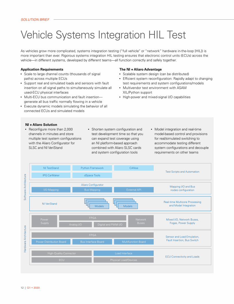
NI + Aliaro Solution■ Reconfigure more than 2,000
channels in minutes and store multiple test system configurations with the Aliaro Configurator for SLSC and NI VeriStand
■ Shorten system configuration and test development time so that you can expand test coverage using an NI platform-based approach combined with Aliaro SLSC cards and system configuration tools
■ Model integration and real-time model-based control and provisions for real/simulated switching to accommodate testing different system configurations and decouple requirements on other teams
Vehicle Systems Integration HIL TestAs vehicles grow more complicated, systems integration testing (“full vehicle” or “network” hardware in-the-loop [HIL]) is more important than ever. Rigorous systems integration HIL testing ensures that electronic control units (ECUs) across the vehicle—in different systems, developed by different teams—all function correctly and safely together.
Application Requirements■ Scale to large channel counts (thousands of signal
paths) across multiple ECUs■ Support real and simulated loads and sensors with fault
insertion on all signal paths to simultaneously simulate all used-ECU physical interfaces
■ Multi-ECU bus communication and fault insertion—generate all bus traffic normally flowing in a vehicle
■ Execute dynamic models simulating the behavior of all connected ECUs and simulated models
The NI + Aliaro Advantage ■ Scalable system design (can be distributed)■ Efficient system reconfiguration: Rapidly adapt to changing
test requirements and system configurations/models■ Multivendor test environment with ASAM
XIL/Python support■ High-power and mixed-signal I/O capabilities
Sof
twar
e A
rchi
tect
ure
Har
dwar
e A
rchi
tect
ure
Aliaro Configurator
I/O Mapping Bus Mapping External APIMapping I/O and Bus nodes configuration
NI VeriStandModels Models
Real-time Multicore Processing and Model Integration
Power Supply Analog I/O Digital and PWM I/O
FPGA Network Buses
Mixed I/O, Network Buses,Fogas, Power Supply
FPGA
Power Distribution Board Bus Interface Board Multifunction Board
Sensor and Load Emulation,Fault Insertion, Bus Switch
High-Quality Connector Load Interface
ECU Physical Load/DevicesECU Connectivity and Loads
Test Scripts and AutomationIPG CarMaker dSpace Tools
NI TestStand Python Framework CANoe
ni.com/automotive | 13
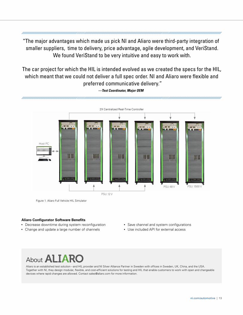
“The major advantages which made us pick NI and Aliaro were third-party integration of smaller suppliers, time to delivery, price advantage, agile development, and VeriStand.
We found VeriStand to be very intuitive and easy to work with.
The car project for which the HIL is intended evolved as we created the specs for the HIL, which meant that we could not deliver a full spec order. NI and Aliaro were flexible and
preferred communicative delivery.”—Test Coordinator, Major OEM
AboutAliaro is an established test solution—and HIL provider and NI Silver Alliance Partner in Sweden with offices in Sweden, UK, China, and the USA. Together with NI, they design modular, flexible, and cost-efficient solutions for testing and HIL that enable customers to work with open and changeable devices where rapid changes are allowed. Contact [email protected] for more information.
Figure 1. Aliaro Full Vehicle HIL Simulator
2X Centralized Real-Time Controller
PSU 12 V
Host PC
PSU 48 V PSU 1500 V
Aliaro Configurator Software Benefits■ Decrease downtime during system reconfiguration ■ Change and update a large number of channels
■ Save channel and system configurations ■ Use included API for external access
14 | Q1 + 2020
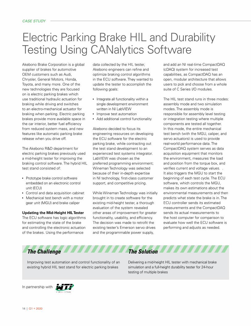
Electric Parking Brake HIL and Durability Testing Using CANalytics SoftwareAkebono Brake Corporation is a global supplier of brakes for automotive OEM customers such as Audi, Chrysler, General Motors, Honda, Toyota, and many more. One of the new technologies they are focused on is electric parking brakes which use traditional hydraulic actuation for braking while driving and switches to an electro-mechanical actuator for braking when parking. Electric parking brakes provide more available space in the car interior, better fuel efficiency from reduced system mass, and new features like automatic parking brake release when you drive off.
The Akebono R&D department for electric parking brakes previously used a mid-height tester for improving the braking control software. The hybrid HIL test stand consisted of:
■ Prototype brake control software embedded on an electronic control unit (ECU)
■ Control and data acquisition cabinet■ Mechanical test bench with a motor
gear unit (MGU) and brake caliper
Updating the Mid-Height HIL Tester The ECU software has logic algorithms for estimating the state of the brake and controlling the electronic actuation of the brakes. Using the performance
data collected by the HIL tester, Akebono engineers can refine and optimize braking control algorithms in the ECU software. They wanted to update the tester to accomplish the following goals:
■ Integrate all functionality within a single development environment written in NI LabVIEW
■ Improve test automation■ Add additional control functionality
Akebono decided to focus its engineering resources on developing the ECU software for the electric parking brake, while contracting out the test stand development to an experienced test systems integrator. LabVIEW was chosen as the preferred programming environment; Wineman Technology was selected because of their in-depth expertise in NI technology, first-class customer support, and competitive pricing.
While Wineman Technology was initially brought in to create software for the existing mid-height tester, a thorough evaluation of the system revealed other areas of improvement for greater functionality, usability, and efficiency. The decision was made to retrofit the existing tester’s Emerson servo drives and the programmable power supply,
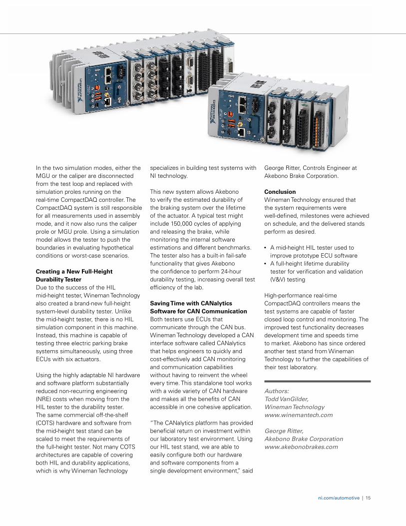
and add an NI real-time CompactDAQ (cDAQ) system for increased test capabilities, as CompactDAQ has an open, modular architecture that allows users to pick and choose from a whole suite of C Series I/O modules.
The HIL test stand runs in three modes: assembly mode and two simulation modes. The assembly mode is responsible for assembly level testing or integration testing where multiple components are tested all together. In this mode, the entire mechanical test bench (with the MGU, caliper, and servo actuators) is used to provide real-world performance data. The CompactDAQ system serves as data acquisition equipment that monitors the environment, measures the load and position from the torque box, and verifies current and voltage values. . It also triggers the MGU to start the beginning of each test cycle. The ECU software, which controls the MGU, makes its own estimations about the environmental measurements and then predicts what state the brake is in. The ECU controller sends its estimated measurements and the CompactDAQ sends its actual measurements to the host computer for comparison to evaluate how well the ECU software is performing and adjusts as needed.
The Challenge
Improving test automation and control functionality of an existing hybrid HIL test stand for electric parking brakes
The Solution
Delivering a mid-height HIL tester with mechanical brake simulation and a full-height durability tester for 24-hour testing of multiple brakes
In partnership with
CASE STUDY
ni.com/automotive | 15
In the two simulation modes, either the MGU or the caliper are disconnected from the test loop and replaced with simulation proles running on the real-time CompactDAQ controller. The CompactDAQ system is still responsible for all measurements used in assembly mode, and it now also runs the caliper prole or MGU prole. Using a simulation model allows the tester to push the boundaries in evaluating hypothetical conditions or worst-case scenarios. Creating a New Full-Height Durability Tester Due to the success of the HIL mid-height tester, Wineman Technology also created a brand-new full-height system-level durability tester. Unlike the mid-height tester, there is no HIL simulation component in this machine. Instead, this machine is capable of testing three electric parking brake systems simultaneously, using three ECUs with six actuators.
Using the highly adaptable NI hardware and software platform substantially reduced non-recurring engineering (NRE) costs when moving from the HIL tester to the durability tester. The same commercial off-the-shelf (COTS) hardware and software from the mid-height test stand can be scaled to meet the requirements of the full-height tester. Not many COTS architectures are capable of covering both HIL and durability applications, which is why Wineman Technology
specializes in building test systems with NI technology.
This new system allows Akebono to verify the estimated durability of the braking system over the lifetime of the actuator. A typical test might include 150,000 cycles of applying and releasing the brake, while monitoring the internal software estimations and different benchmarks. The tester also has a built-in fail-safe functionality that gives Akebono the confidence to perform 24-hour durability testing, increasing overall test efficiency of the lab. Saving Time with CANalytics Software for CAN Communication Both testers use ECUs that communicate through the CAN bus. Wineman Technology developed a CAN interface software called CANalytics that helps engineers to quickly and cost-effectively add CAN monitoring and communication capabilities without having to reinvent the wheel every time. This standalone tool works with a wide variety of CAN hardware and makes all the benefits of CAN accessible in one cohesive application.
“The CANalytics platform has provided beneficial return on investment within our laboratory test environment. Using our HIL test stand, we are able to easily configure both our hardware and software components from a single development environment,” said
George Ritter, Controls Engineer at Akebono Brake Corporation. Conclusion Wineman Technology ensured that the system requirements were well-defined, milestones were achieved on schedule, and the delivered stands perform as desired.
■ A mid-height HIL tester used to improve prototype ECU software
■ A full-height lifetime durability tester for verification and validation (V&V) testing
High-performance real-time CompactDAQ controllers means the test systems are capable of faster closed loop control and monitoring. The improved test functionality decreases development time and speeds time to market. Akebono has since ordered another test stand from Wineman Technology to further the capabilities of their test laboratory.
Authors: Todd VanGilder, Wineman Technology www.winemantech.com George Ritter, Akebono Brake Corporation www.akebonobrakes.com

16 | Q1 + 2020
SOLUTION BRIEFD
UT
(Dev
ice
Und
er T
est)
Virg
inia
Pan
el C
onne
ctor
(iC
on)
Host Interface
AliaroConfigurator
NI VeriStand
User Interface
Model Interface
Real-Time Controller (NI PXI/CompactRIO)
Programmable Power Supplies
FPGA
Real-Time Processor
NI VeriStand Real-Time
Engine
Networks
Analog
D/A
A/D
Power Supply Power Supply
Interface Box (NI SLSC)
Bus Switch SLSC Board
Multifunction SLSC Board
Fault Insertion
Fault Insertion
Signal Conditioning
Network Mapping
Digital I/O
Pulse-Width Modulation
Sensor Simulation
Load Simulation
HIL Cabinet also includes PDU (Power Distribution Units), safety switching, and high-end cables
19" Rack (from 10U to 38U)
Body ECU HIL Test Increasingly sophisticated and interconnected interior, infotainment, and advanced driver-assistance (ADAS) systems have expanded the number and complexity of body electronic control units (ECUs)—from active suspension, braking, and emergency steering to seat control and rearview mirror ECUs integrated with infotainment systems. When testing the embedded software on these ECUs, safety, availability, or cost considerations can make it impractical to perform the necessary validation tests using a complete system. Hardware-in-the-Loop (HIL) test methodology brings test earlier in the design cycle. Creating that tester on a software-defined platform makes for a flexible system that can adapt as ECU design and test requirements change.
NI + Aliaro Solution■ If your ECU pinout changes, quickly
reconfigure your system setup using Aliaro Configurator Software and the Aliaro AL-1010 switch load signal conditioning (SLSC) module, which provides flexible I/O, signal conditioning, and switching capabilities on each channel, and fault injection on all pins
■ User-friendly model integration with NI VeriStand for sensor and actuation simulation, and I/O interfacing with NI PXI and CompactRIO hardware incorporating the latest Xilinx FPGA technology for µs-level, real-time, model-based simulation of power electronics, actuation, and sensors
■ Suitable for multi-vendor test environments with an open platform and support for ASAM XIL, CANoe, dSPACE ControlDesk, and a number of Python frameworks
Application Requirements■ Adapt to inevitable changes in signal lists and
I/O requirements■ Conduct fault insertion and signal conditioning■ Integrate models, third-party devices, and toolkits to
accurately simulate the full system
The NI Advantage■ Minimize cost and ensure reliability with HIL test
methodology, reducing the need for costly real-world tests■ Reduce test development time and enjoy quick startup
with a turnkey system built with Aliaro’s integration and NI’s modular platform
■ Maximize system reuse with a flexible tester designed to be extended and customized to meet your changing requirements
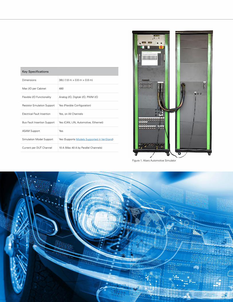
Figure 1. Aliaro Automotive Simulator
Key Specifications
Dimensions 38U (1.8 m × 0.6 m × 0.8 m)
Max I/O per Cabinet 480
Flexible I/O Functionality Analog I/O, Digitak I/O, PWM I/O
Resistor Emulation Support Yes (Flexible Configuration)
Electrical Fault Insertion Yes, on All Channels
Bus Fault Insertion Support Yes (CAN, LIN, Automotive, Ethernet)
ASAM Support Yes
Simulation Model Support Yes (Supports Models Supported in VeriStand)
Current per DUT Channel 10 A (Max 40 A by Parallel Channels)
18 | Q1 + 2020
Closing The Loop: 5 HIL Trends for Chassis and Body Electronics TestAccording to FMI’s Automotive Electronic Control Unit (ECU) Market Assessment, the global market for ECUs—including engine, brake, suspension, and body control modules—is forecasted to grow at a strong CAGR of 7.1% through the period of 2017–2022. The race to creating smarter, safer, and cleaner cars for the mass market is tighter than ever, and with that comes the pressure to speed up the R&D cycle while still providing comprehensive, bulletproof testing that roots out potential problem areas.
Hardware-in-the-loop (HIL) simulation is a key technology commonly used in transportation industries for testing control modules for engines and transmissions. With the complexity of powertrain systems, design departments have been using HIL for a while to test embedded software and controllers with actual hardware components to simulate real-world conditions. However, many body electronics and body control modules (BCMs—such as for heating and cooling, seats, and keyless entry—have traditionally used open-loop control for basic monitoring and stimulation.
With today’s HIL technology and the greater availability of controller software models, it’s easier than ever to close the loop. Closed-loop testing provides more accurate data and better test coverage, which means a better chance of finding any anomalies earlier in the development cycle when it’s easier (and cheaper) to fix. Common HIL applications include:
Software regression testing: Every time a new software feature is added, all previously existing functionality must be thoroughly tested again to ensure nothing’s been broken—a time-consuming yet necessary evil. HIL systems can greatly speed up this process by using ECU simulation models, reusable test scripts, and test-case generation. Imagine the time savings that comes from running automated regression testing 24/7 even when the lights are out.
Real-world hardware simulation: HIL allows us to put a device under test (DUT) under the rigors of actual hardware signals and loads that represent the real-world transducers found in a vehicle. By providing more accurate environments and scenarios for the DUT, the controller software and hardware can be truly fine-tuned for optimal performance.
The Challenges of Joining the HIL World
If closed loop test is so wonderful and easy, then why hasn’t everyone jumped on the HIL bandwagon?
High Costs In the past, HIL testers have been sold as closed-box turnkey products, bundled with all the hardware and software you should need. However, depending on the size of your application, it may not be worthwhile (or in your budget) to buy even the smallest package offered when you’re only going to use half the functions. Is there any way to pay for only the features you need? Proprietary Technology Speaking of closed-box systems, what happens if you purchase the HIL stand and then need to add new ECU test functionality further down the road?
■ Option A: you can contact the manufacturer, make another purchase order, and then wait at their pleasure until the HIL tester is upgraded and ready for use again.
■ Option B: one of your own engineers can fashion a custom PCB to get the job done… but what happens when that person leaves the company and all that tribal knowledge leaves with them?
Bottom line: many engineers may balk at adding HIL testing because the conventional options are too pricy, limited, or don’t quite fit their needs. Luckily, there’s another way. In order to keep up with a rapidly changing market, you need an open box HIL system that:
■ Can be customized by your own engineers or a system integrator
■ Has a modular architecture for easy future expansion■ Uses commercial off-the-shelf (COTS) technology that
is readily available■ Plays well with industry standards and tools from
other vendors
WHITE PAPER
ni.com/automotive | 19
Top 5 HIL Trends to Make Your Life Easier
With decades of building test machines under our belt, our engineering experts at Wineman Technology believe in standardizing HIL systems on NI’s comprehensive technology platform because its adaptability and high performance can handle any challenge we tackle. Here are the top reasons why NI equipment is well-suited for HIL simulation in automotive, off-road, and large machinery applications:
#1 Open Architecture With chassis and body electronics evolving so quickly nowadays, sometimes the test technologies to evaluate them may not even exist yet. While it’s impossible to completely future-proof any HIL system you create, using an open architecture makes it much easier to implement cutting-edge tools and adapt future features down the road.
Building an HIL test stand with an open architecture has significant advantages, allowing you to reconfigure software functionality when needed and plug in your own code into the system.
We use NI VeriStand, a powerful real-time testing and simulation software, not only because of the comprehensive functionality but also its openness to third-party software and models. The easy-to-use, configuration based environment takes care of everything—from system setup and stimulus generation to model execution and user interface creation. Plus, custom code from LabVIEW, Python®, ANSI C/C++, ASAM XIL, and more can be plugged into VeriStand to include additional functionality.
In fact, one of our favorite VeriStand features is its ability to accept models from The MathWorks, Inc. Simulink® software, SimulationX from ITI, Dymola from Dynasim, and many other modeling platforms without extra licensing fees, by easily compiling the model into a library using the Model Interface Framework. Just take any model from your favorite compiler and import it seamlessly into VeriStand.
#2 COTS Technology In order to test the latest chassis and BCM improvements, you can either build your own custom devices or look at what COTS options are available. Using off-the-shelf components makes
life easier for everyone, especially when it comes to upgrading your system or buying replacement parts. Because NI uses modular hardware and configuration-based software, anyone can purchase a new PXI or C Series module and set it up themselves. Another reassuring thing about using COTS tools from NI is that the company is a well-established, billion-dollar corporation. So if you have questions about or issues with your products, NI provides excellent customer support and a large network of system integrators that are just a phone call or email away.
One recent HIL-specific innovation NI released is an ecosystem of SLSC modules for switch, load, and signal conditioning. Usually engineers must build their own custom solutions or rely on a one-off product to connect data acquisition I/O to the ECU or DUT. Now that the SLSC line bridges the gap between NI’s data acquisition platform and the ECU, we can create a completely COTS-based HIL architecture that tightly integrates and runs under the same software, resulting in cost and time savings.
20 | Q1 + 2020
#3 Deterministic Timing and Custom Protocols with FPGAs Most HIL test systems run different nodes of computation, such as Windows, for the host computer and a real-time operating system for the controllers, and these nodes have varying amounts of processing time and jitter. But what if your test specifications require extremely deterministic processing times in the submicrosecond range? That’s where customizable field-programmable gate arrays (FPGAs) come into play. FPGAs are user-programmable chips that can bypass the operating system and perform the most deterministic, high-speed calculations. With NI technology, developers have complete access to the FPGA using LabVIEW graphical programming or VHDL code.
When real-time HIL testing requires nanosecond accuracy, you can use FPGAs to implement sensor and actuator simulation, closed-loop control algorithms, and custom communication protocols. With all the sensor fusion being added into vehicles, each with their own evolving protocols, FPGAs allow you to create and use brand new protocols before they’ve been released to the market. For example, vehicle camera and vehicle-to-vehicle and vehicle-to-infrastructure (V2X) wireless communication may be used to detect that another car is going to run a red light. Serial protocols on an FPGA can be used to simulate the situation and see how the braking system reacts. The same scenario would be time-consuming and expensive to recreate in the real world, much less on a repeatable basis.
#4 RF Wireless Communication With the mass movement towards intelligent vehicles and global connectivity, today’s cars can come equipped with everything from keyless entry and Bluetooth integration to satellite radio and global navigation satellite systems (GNSS). New
safety features on the market include advanced driver assistance systems (ADAS), LiDAR obstacle detection, and V2X communication. All of these different connectivity technologies require RF testing to verify and fine-tune proper operation.
HIL systems for these BCMs and embedded controllers may require RF measurement and generation for direct testing of RF functionality or embedded software synchronization and triggering. For example, an HIL system testing ADAS may involve receiving a radar signal, manipulating it to insert a simulated object (such as a deer on the road) using a vector signal transceiver, and sending it out to the chassis or body ECU to evaluate its response. In these cases, NI has best-in-class RF and wireless solutions that allow engineers to easily expand their HIL capabilities whenever and however needed.
#5 Standardization with ASAM XIL Perhaps you’re interested in adding HIL simulation and other new functionality from NI, but you already have existing test equipment or software stacks from a mix of other suppliers. NI fully supports ASAM XIL, an automotive test API standard developed for model-in-the-loop (MIL), software-in-the-loop (SIL), and HIL applications. ASAM XIL
is supported by major test automation providers, such as NI, dSPACE, ETAS, and Vector. That means if you’re using one vendor’s library of test automation scripts, you can use their software to talk to and control NI’s open, modular hardware. And vice versa—NI’s configuration-based software can communicate with and run other vendors’ ASAM-compliant hardware. Having this test API compatibility makes it easier for companies to try out new platforms and upgrade their test stands over time.
Don’t Settle for Open-Loop Testing The rise in intelligent vehicles is increasing the complexity of chassis and body control electronics, and engineers need a fast, accurate, and automated way to systematically test functionality while eliminating potential points of failure. The openness and flexibility of NI hardware and software give you the freedom to:
■ Design a customizable, cost-effective HIL system
■ Update an existing system and reuse equipment
■ Easily add hardware I/O or software functions as needed
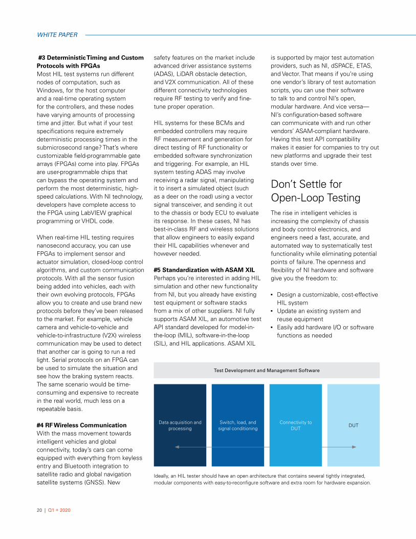
Ideally, an HIL tester should have an open architecture that contains several tightly integrated, modular components with easy-to-reconfigure software and extra room for hardware expansion.
Data acquisition and processing
Switch, load, and signal conditioning
Connectivity toDUT
DUT
Test Development and Management Software
WHITE PAPER
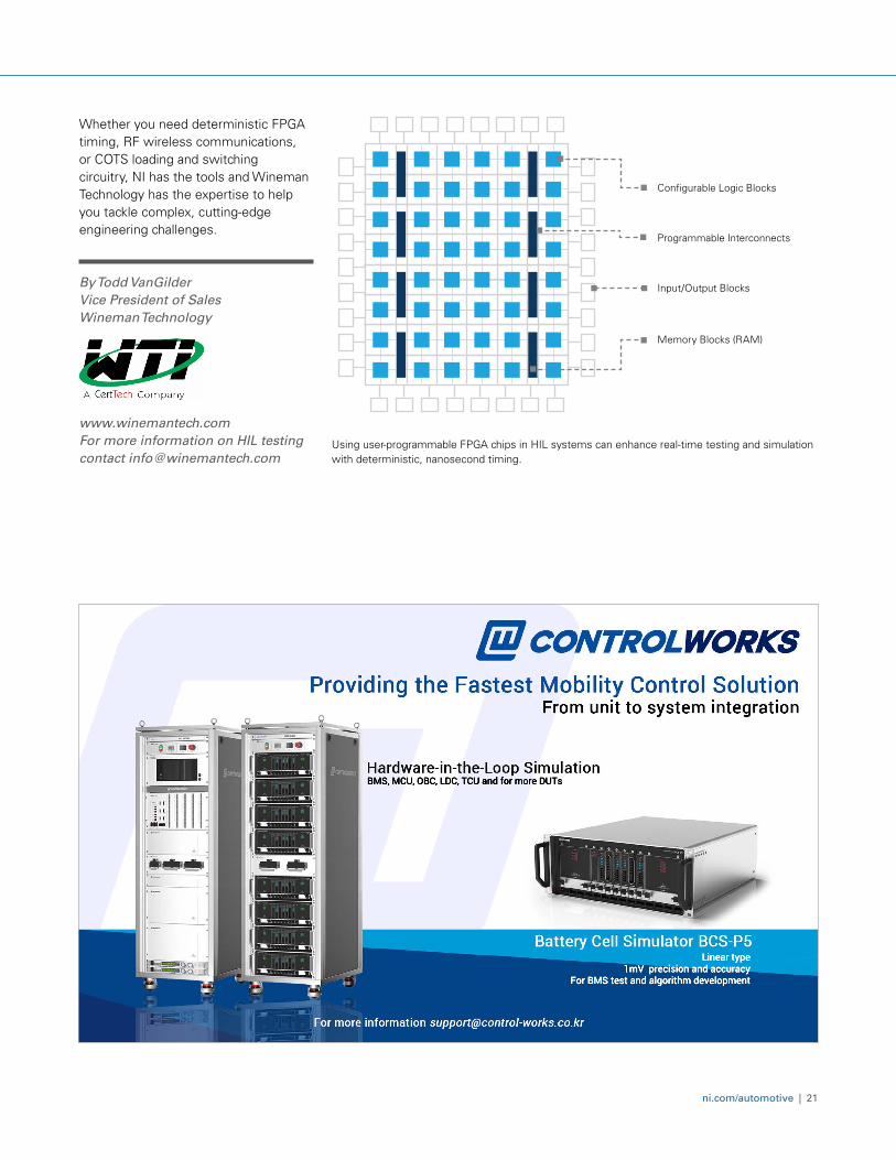
Input/Output Blocks
Programmable Interconnects
Memory Blocks (RAM)
Configurable Logic Blocks
ni.com/automotive | 21
Whether you need deterministic FPGA timing, RF wireless communications, or COTS loading and switching circuitry, NI has the tools and Wineman Technology has the expertise to help you tackle complex, cutting-edge engineering challenges.
By Todd VanGilder Vice President of Sales Wineman Technology
www.winemantech.com For more information on HIL testing contact [email protected]
BMS, MCU, OBC, LDC, TCU and for more DUTs
Linear type1mV precision and accuracy
For BMS test and algorithm development
Using user-programmable FPGA chips in HIL systems can enhance real-time testing and simulation with deterministic, nanosecond timing.
22 | Q1 + 2020
SOLUTION BRIEF
End-of-line
Trove Data Archival
Server
HMI Control and Visualization
STAX Automationand Control
Shield NVH MetricDeployment
Quality
Engineer
Technician
Operator
NI PXI or CompactRIOReal-time Controller
Machine
DUTUse
rs
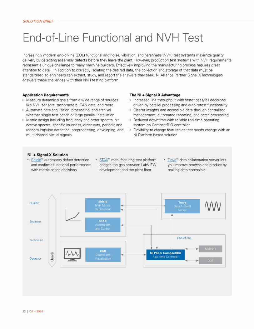
End-of-Line Functional and NVH Test Increasingly modern end-of-line (EOL) functional and noise, vibration, and harshness (NVH) test systems maximize quality delivery by detecting assembly defects before they leave the plant. However, production test systems with NVH requirements represent a unique challenge to many machine builders. Effectively improving the manufacturing process requires great attention to detail. In addition to correctly isolating the desired data, the collection and storage of that data must be standardized so engineers can extract, study, and report the answers they seek. NI Alliance Partner Signal.X Technologies answers these challenges with their NVH testing platform.
Application Requirements■ Measure dynamic signals from a wide range of sources
like NVH sensors, tachometers, CAN data, and more■ Automate data acquisition, processing, and archival
whether single test bench or large parallel installation■ Metric design including frequency and order spectra, nth
octave spectra, specific loudness, order cuts, periodic and random impulse detection, preprocessing, enveloping, and multi-channel virtual signals
The NI + Signal.X Advantage ■ Increased line throughput with faster pass/fail decisions
driven by parallel processing and auto-retest functionality■ Clearer insights and accessible data through centralized
management, automated reporting, and batch processing■ Reduced downtime with reliable real-time operating
system on CompactRIO controller■ Flexibility to change features as test needs change with an
NI Platform based solution
NI + Signal.X Solution ■ Shield™ automates defect detection
and confirms functional performance with metric-based decisions
■ STAX™ manufacturing test platform bridges the gap between LabVIEW development and the plant floor
■ Trove™ data collaboration server lets you improve process and product by making data accessible
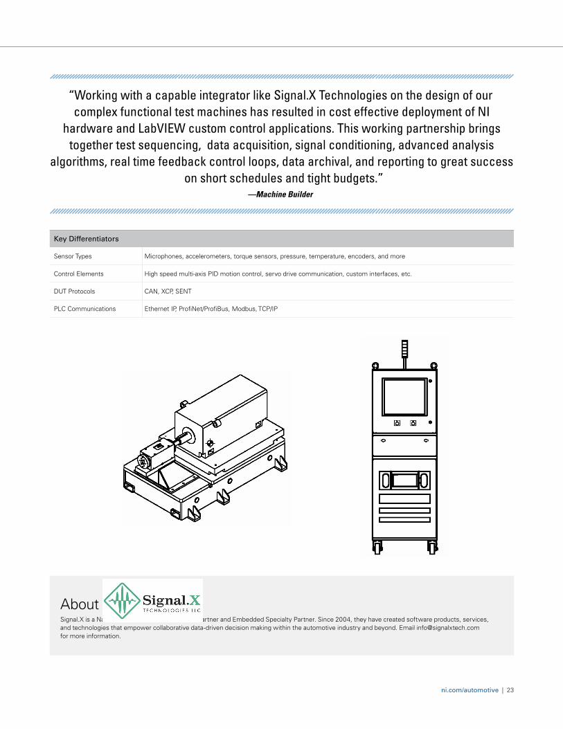
Key Differentiators
Sensor Types Microphones, accelerometers, torque sensors, pressure, temperature, encoders, and more
Control Elements High speed multi-axis PID motion control, servo drive communication, custom interfaces, etc.
DUT Protocols CAN, XCP, SENT
PLC Communications Ethernet IP, ProfiNet/ProfiBus, Modbus, TCP/IP
ni.com/automotive
Key Differentiators Sensor Types Microphones, accelerometers, torque sensors,
pressure, temperature, encoders, and more Control Elements High speed multi-axis PID motion control, servo
drive communication, custom interfaces, etc. DUT Protocols CAN, XCP, SENT PLC Communications Ethernet IP, ProfiNet/ProfiBus, Modbus, TCP/IP
Success on Short Schedules and Tight Budgets “Working with a capable integrator like Signal.X Technologies on the design of our complex functional test machines has resulted in cost effective deployment of NI hardware and LabVIEW custom control applications. This working partnership brings together test sequencing, data acquisition, signal conditioning, advanced analysis algorithms, real time feedback control loops, data archival, and reporting to great success on short schedules and tight budgets.”
- Machine Builder
Contact your NI account manager or call or e-mail Signal.X Technologies to learn more about how we can meet your NVH and functional testing needs.
734-738-0777 [email protected]
Signal.X Technologies Signal.X is a National Instruments Gold Alliance Partner and Embedded Specialty Partner. Since 2004 they have created software products, services and technologies that empower collaborative data-driven decision making within the automotive industry and beyond.
ni.com/automotive | 23
“Working with a capable integrator like Signal.X Technologies on the design of our complex functional test machines has resulted in cost effective deployment of NI
hardware and LabVIEW custom control applications. This working partnership brings together test sequencing, data acquisition, signal conditioning, advanced analysis
algorithms, real time feedback control loops, data archival, and reporting to great success on short schedules and tight budgets.”
—Machine Builder
AboutSignal.X is a National Instruments Gold Alliance Partner and Embedded Specialty Partner. Since 2004, they have created software products, services, and technologies that empower collaborative data-driven decision making within the automotive industry and beyond. Email [email protected] for more information.
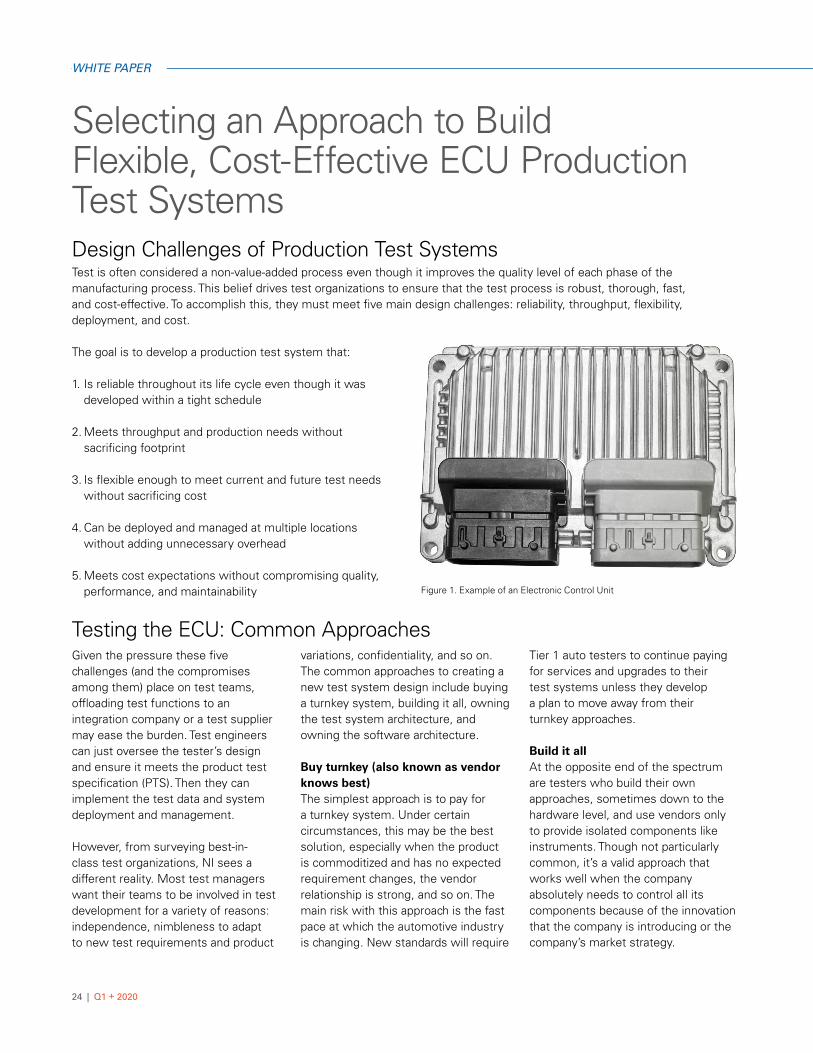
Figure 1. Example of an Electronic Control Unit
24 | Q1 + 2020
WHITE PAPER
Selecting an Approach to Build Flexible, Cost-Effective ECU Production Test Systems
Test is often considered a non-value-added process even though it improves the quality level of each phase of the manufacturing process. This belief drives test organizations to ensure that the test process is robust, thorough, fast, and cost-effective. To accomplish this, they must meet five main design challenges: reliability, throughput, flexibility, deployment, and cost.
The goal is to develop a production test system that:
1. Is reliable throughout its life cycle even though it was developed within a tight schedule
2. Meets throughput and production needs without sacrificing footprint
3. Is flexible enough to meet current and future test needs without sacrificing cost
4. Can be deployed and managed at multiple locations without adding unnecessary overhead
5. Meets cost expectations without compromising quality, performance, and maintainability
Given the pressure these five challenges (and the compromises among them) place on test teams, offloading test functions to an integration company or a test supplier may ease the burden. Test engineers can just oversee the tester’s design and ensure it meets the product test specification (PTS). Then they can implement the test data and system deployment and management.
However, from surveying best-in-class test organizations, NI sees a different reality. Most test managers want their teams to be involved in test development for a variety of reasons: independence, nimbleness to adapt to new test requirements and product
variations, confidentiality, and so on. The common approaches to creating a new test system design include buying a turnkey system, building it all, owning the test system architecture, and owning the software architecture.
Buy turnkey (also known as vendor knows best)The simplest approach is to pay for a turnkey system. Under certain circumstances, this may be the best solution, especially when the product is commoditized and has no expected requirement changes, the vendor relationship is strong, and so on. The main risk with this approach is the fast pace at which the automotive industry is changing. New standards will require
Tier 1 auto testers to continue paying for services and upgrades to their test systems unless they develop a plan to move away from their turnkey approaches.
Build it allAt the opposite end of the spectrum are testers who build their own approaches, sometimes down to the hardware level, and use vendors only to provide isolated components like instruments. Though not particularly common, it’s a valid approach that works well when the company absolutely needs to control all its components because of the innovation that the company is introducing or the company’s market strategy.
Testing the ECU: Common Approaches
Design Challenges of Production Test Systems
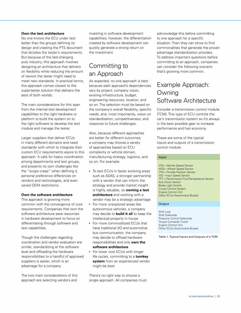
Table 1. Typical Inputs and Outputs of a TCM
Input
VSS—Vehicle Speed SensorWSS—Wheel Speed SensorTPS—Throttle Position SensorISS—Input Speed SensorTFT—Transmission Fluid Temperature SensorKick Down SwitchBrake Light SwitchCruise Control SystemEngine Control UnitOther ECUs (Automotive Buses)
Output
Shift LockShift SolenoidsPressure Control SolenoidsTorque Converter ClutchEngine Control UnitOther ECUs (Automotive Buses)
ni.com/automotive | 25
Own the test architectureNo one knows the ECU under test better than the groups defining its design and creating the PTS document that dictates the tester’s requirements. But because of the fast-changing auto industry, this approach involves designing an architecture that delivers on flexibility while reducing the amount of rework the tester might need to meet new standards. In practical terms, this approach comes closest to the super-tester solution that delivers the best of both worlds.
The main considerations for this span from the internal test development capabilities to the right hardware or platform to build the system on to the right software to develop the test module and manage the tester.
Larger suppliers that deliver ECUs in many different domains and need standards with which to integrate their custom ECU requirements aspire to this approach. It calls for heavy coordination among departments and test groups, and presents its own challenges like the “scope creep” when defining it, personal preference differences on vendors and technologies, and even varied OEM restrictions.
Own the software architectureThis approach is growing more common with the convergence of core requirements. Companies that own the software architecture save resources in hardware development to focus on differentiating through software and test capabilities.
Though the challenges regarding coordination and vendor evaluation are similar, standardizing at the software level and offloading the hardware responsibilities to a handful of approved suppliers is easier, which is an advantage for a company.
The two main considerations of this approach are selecting vendors and
investing in software development capabilities; however, the differentiation created by software development can quickly generate a strong return on the investment.
Committing to an ApproachAs expected, no one approach is best because each approach’s dependencies vary by project, company vision, existing infrastructure, budget, engineering resources, location, and so on. The selection must be based on the company’s overall flexibility, specific needs, and, most importantly, vision on standardization, competitiveness, and response to future challenges.
Also, because different approaches are better for different outcomes, a company may choose a variety of approaches based on ECU complexity or vehicle domain, manufacturing strategy, logistics, and so on. For example:
■ To test ECUs in faster evolving areas such as ADAS, a stronger partnership with a vendor that can inform the strategy and provide market insight is highly valuable, so owning a test architecture and working with a vendor may be a strategic advantage
■ For more unexplored areas like autonomous vehicles, a company may decide to build it all to keep the intellectual property in house
■ For more commoditized ECUs that have traditional I/O and automotive bus communication, the company may decide to offload hardware responsibilities and only own the software architecture
■ For lower cost ECUs with longer life cycles, committing to a turnkey system from an experienced vendor might be best
There’s no right way to choose a single approach. All companies must
acknowledge this before committing to one approach for a specific situation. Then they can strive to find commonalities that generate the proven advantage standardization provides. To address important questions before committing to an approach, companies can consider the following scenario that’s growing more common.
Example Approach: Owning Software ArchitectureConsider a transmission control module (TCM). This type of ECU controls the car’s transmission system so it’s always in the best possible gear to increase performance and fuel economy.
These are some of the typical inputs and outputs of a transmission control module:
Transmission Control Module
Accelerometer Temperature
Memory Processor
Safety CalibrationDiagnostics
Power
CAN
LIN
FlexRay
Hall-Effect Input
Analog Input
PWM Input
Speed Input
Current Output
Switch Output H/L PowerH/L Side
BLDC Output
Speed Output
Other OutputOther Input
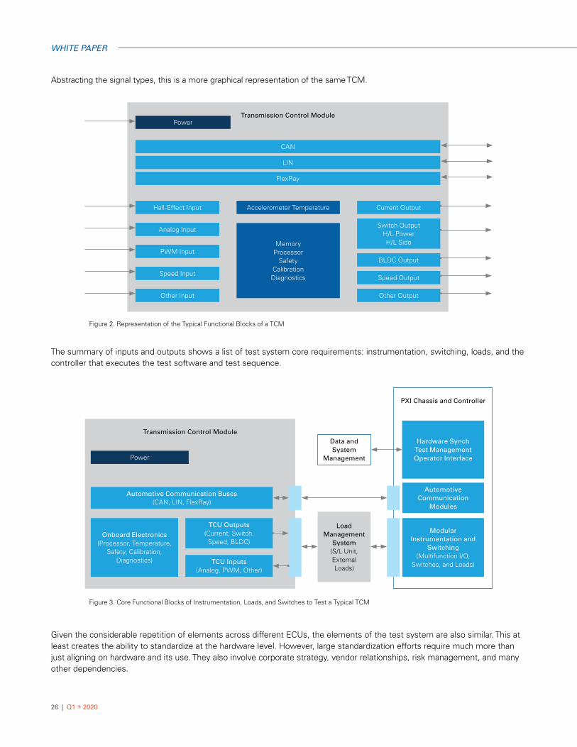
Figure 2. Representation of the Typical Functional Blocks of a TCM
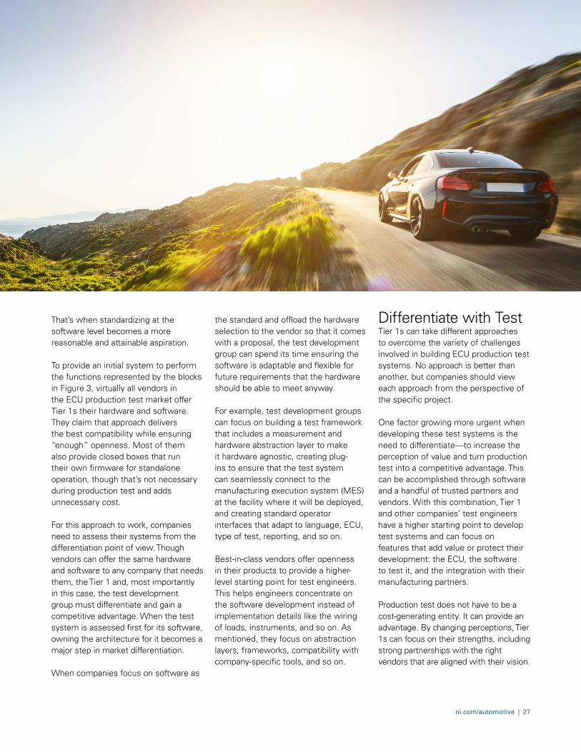
Figure 3. Core Functional Blocks of Instrumentation, Loads, and Switches to Test a Typical TCM
Transmission Control Module
Load Management
System(S/L Unit, External Loads)
Data and System
Management
PXI Chassis and Controller
Automotive Communication
Modules
Modular Instrumentation and
Switching(Multifunction I/O,
Switches, and Loads)
Hardware SynchTest ManagementOperator Interface
Automotive Communication Buses(CAN, LIN, FlexRay)
Onboard Electronics(Processor, Temperature,
Safety, Calibration, Diagnostics)
TCU Outputs(Current, Switch,
Speed, BLDC)
TCU Inputs(Analog, PWM, Other)
Power
26 | Q1 + 2020
WHITE PAPER
Abstracting the signal types, this is a more graphical representation of the same TCM.
The summary of inputs and outputs shows a list of test system core requirements: instrumentation, switching, loads, and the controller that executes the test software and test sequence.
Given the considerable repetition of elements across different ECUs, the elements of the test system are also similar. This at least creates the ability to standardize at the hardware level. However, large standardization efforts require much more than just aligning on hardware and its use. They also involve corporate strategy, vendor relationships, risk management, and many other dependencies.
ni.com/automotive | 27
That’s when standardizing at the software level becomes a more reasonable and attainable aspiration.
To provide an initial system to perform the functions represented by the blocks in Figure 3, virtually all vendors in the ECU production test market offer Tier 1s their hardware and software. They claim that approach delivers the best compatibility while ensuring “enough” openness. Most of them also provide closed boxes that run their own firmware for standalone operation, though that’s not necessary during production test and adds unnecessary cost.
For this approach to work, companies need to assess their systems from the differentiation point of view. Though vendors can offer the same hardware and software to any company that needs them, the Tier 1 and, most importantly in this case, the test development group must differentiate and gain a competitive advantage. When the test system is assessed first for its software, owning the architecture for it becomes a major step in market differentiation. When companies focus on software as
the standard and offload the hardware selection to the vendor so that it comes with a proposal, the test development group can spend its time ensuring the software is adaptable and flexible for future requirements that the hardware should be able to meet anyway.
For example, test development groups can focus on building a test framework that includes a measurement and hardware abstraction layer to make it hardware agnostic, creating plug-ins to ensure that the test system can seamlessly connect to the manufacturing execution system (MES) at the facility where it will be deployed, and creating standard operator interfaces that adapt to language, ECU, type of test, reporting, and so on.
Best-in-class vendors offer openness in their products to provide a higher-level starting point for test engineers. This helps engineers concentrate on the software development instead of implementation details like the wiring of loads, instruments, and so on. As mentioned, they focus on abstraction layers, frameworks, compatibility with company-specific tools, and so on.
Differentiate with Test Tier 1s can take different approaches to overcome the variety of challenges involved in building ECU production test systems. No approach is better than another, but companies should view each approach from the perspective of the specific project.
One factor growing more urgent when developing these test systems is the need to differentiate—to increase the perception of value and turn production test into a competitive advantage. This can be accomplished through software and a handful of trusted partners and vendors. With this combination, Tier 1 and other companies’ test engineers have a higher starting point to develop test systems and can focus on features that add value or protect their development: the ECU, the software to test it, and the integration with their manufacturing partners.
Production test does not have to be a cost-generating entity. It can provide an advantage. By changing perceptions, Tier 1s can focus on their strengths, including strong partnerships with the right vendors that are aligned with their vision.
28 | Q1 + 2020
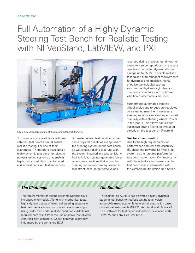
Full Automation of a Highly Dynamic Steering Test Bench for Realistic Testing with NI VeriStand, LabVIEW, and PXI
To minimize costly road tests with test vehicles, test benches must enable realistic testing. For one of their customers, ITK therefore developed a highly dynamic test bench for electric power steering systems that enables haptic tests in addition to automated and simulation-based test sequences.
To create realistic test conditions, the same physical quantities are applied to the steering system on the test bench as would occur during test runs with the system installed in a test vehicle. A hydraulic load actuator generates forces or assumes positions that act on the steering system and are equivalent to real street loads. Target force values
recorded during previous test drives, for example, can be reproduced on the test bench and controlled dynamically over a range up to 25 kN. To enable realistic testing and fulfill stringent requirements for dynamics and precision, highly effective technologies such as synchronized hydraulic cylinders and mechanical structures with optimized vibration characteristics are used.
Furthermore, automated steering wheel angles and torques are regulated by a steering machine. If necessary, steering motions can also be performed manually with a steering wheel (“driver-in-the-loop”). This allows haptics and subjective driving feel to be evaluated directly on the test bench. (Figure 1)
Test bench automationDue to the high requirements for performance and real-time capability, ITK chose the powerful NI PXIe-8135 system as the run-time platform for test bench automation. Communication with the actuators and sensors of the test bench was implemented with the versatile multifunction NI X Series
CASE STUDY
The Challenge
The requirements for testing steering systems have increased enormously. Along with mechanical tests, highly dynamic tests of electrical steering systems on test benches are now common and are increasingly being performed under realistic conditions. Additional requirements result from the use of active test objects with their own actuators, whose behavior is strongly influenced by the contained ECU.
The Solution
ITK Engineering AG (ITK) has delivered a highly dynamic steering test bench for realistic testing to an Asian automobile manufacturer. It features full automation based on National Instruments (NI) PXI, VeriStand, and TACware®, ITK’s software for test bench automation, developed with LabVIEW and LabVIEW Real-Time.
Figure 1. Mechanical structure of the steering test bench from ITK
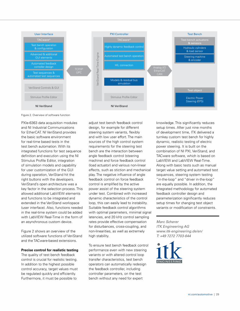
Figure 2. Overview of software function
Test BenchUser Interface PXI Controller
Test bench actuators & sensors
Test object
TACware®
Test bench operation & configuration
Automated feedback contoller design
VeriStand Controls & GUI
Advanced & additional GUI elements
Test sequences & automated test sequences
Stimulus Profile Editor
NI VeriStand
TACware®
NI VeriStand
Highly dynamic feedback control
HIL connection
Models & residual bus simulation
Automated test bench operation Steering machine & encoder
Hydraulic cylinders & load sensor
Stimulus Profile EditorVe
riSta
nd R
eal-T
ime
Eng
ine
Electric Power Steering (EPS)
Analog I/O EtherCAT
CAN
TCP/IPUPC
ni.com/automotive | 29
PXIe-6363 data acquisition modules and NI Industrial Communications for EtherCAT. NI VeriStand provides the basic software environment for real-time based tests in the test bench automation. With its integrated functions for test sequence definition and execution using the NI Stimulus Profile Editor, integration of simulation models and capability for user customization of the GUI during operation, VeriStand hit the right buttons with the developers. VeriStand’s open architecture was a key factor in the selection process. This allowed additional LabVIEW elements and functions to be integrated and extended in the VeriStand workspace (user interface). Also, functions needed in the real-time system could be added with LabVIEW Real-Time in the form of an asynchronous custom device.
Figure 2 shows an overview of the utilized software functions of VeriStand and the TACware-based extensions.
Precise control for realistic testingThe quality of test bench feedback control is crucial for realistic testing. In addition to the highest possible control accuracy, target values must be regulated quickly and efficiently. Furthermore, it must be possible to
adjust test bench feedback control design, for example for different steering system variants, flexibly and with low user effort. The main sources of the high control system requirements for the steering test bench are the interaction between angle feedback control (steering machine) and force feedback control (load actuator) and various non-linear effects, such as stiction and mechanical play. The negative influence of angle feedback control on force feedback control is amplified by the active power assist of the steering system under test. Combined with increased dynamic characteristics of the control loop, this can easily lead to instability. Suitable feedback control algorithms with optimal parameters, minimal signal latencies, and 20 kHz control sampling rates provide effective compensation for disturbances, cross-coupling, and non-linearities, as well as extremely high stability.
To ensure test bench feedback control performance even with new steering variants or with altered control loop transfer characteristics, test bench operators can automatically redesign the feedback controller, including controller parameters, on the test bench without any need for expert
knowledge. This significantly reduces setup times. After just nine months of development time, ITK delivered a turnkey custom test bench for highly dynamic, realistic testing of electric power steering. It is built on the combination of NI PXI, VeriStand, and TACware software, which is based on LabVIEW and LabVIEW Real-Time. Along with basic tests such as manual target value setting and automated test sequences, steering system testing “in-the-loop” and “driver in-the-loop” are equally possible. In addition, the integrated methodology for automated feedback controller design and parameterization significantly reduces setup times for changing test object variants or modification of constraints.
Marc Scherer ITK Engineering AG www.itk-engineering.de/en/ T: +49 7272 7703-644
Station Health
and Operation Functions
Test Steps
Voltage and Current
Opens/Shorts
Electronic Path
Buttons/LEDs
Charge/Discharge Current
Input Power
Input Current
Total Harmonic Distortion
Firmware Verification
Others DUT Handler
Rack: Mechanical, Power, and
Safety
Operation, M
aintenance, and Regulatory D
ocumentation
Manufacturing Execution System (MES)
Systems and Data Management
Instrument Drivers/Configuration Tools
DUT Control Functions
DUT Handler Functions
Test Architecture/Sequence
Debug UITest Steps
Abstraction Layers
Sequence EditorTest UI Data Connectivity and Publishing
Analog and Digital I/O Digital Multimeter Oscilloscope/Digitizer
Waveform Generator Switch Source Measure Unit
Programmable DC Power Supply Electronic Load Instrument Control and Synchronization
Connector/ Mass
InterconnectFixtureComputer/
Controller
Test Station Health
Monitoring Hardware
Display
DUT
NI Product Built Using NI Products Built Using NI Ecosystem Tools From End User or Third Party
Server/Cloud Software
Local Software
Infrastructure
Device
Instrumentation
30 | Q1 + 2020
CASE STUDY
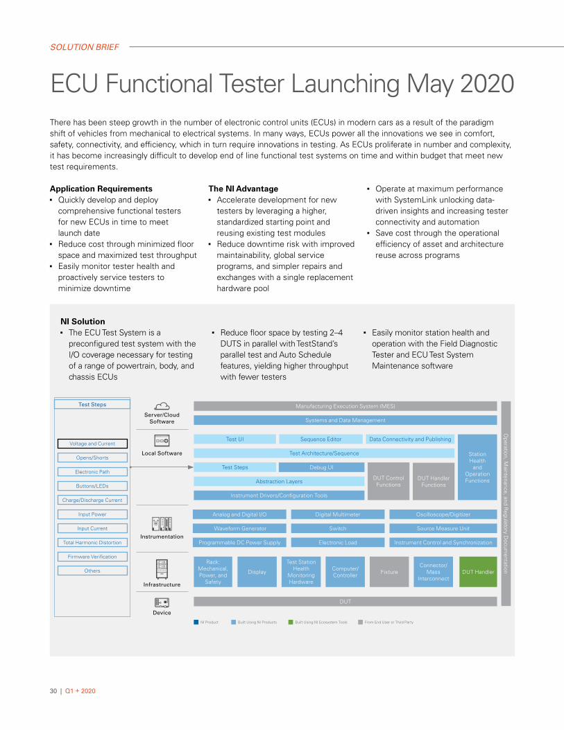
NI Solution■ The ECU Test System is a
preconfigured test system with the I/O coverage necessary for testing of a range of powertrain, body, and chassis ECUs
■ Reduce floor space by testing 2–4 DUTS in parallel with TestStand’s parallel test and Auto Schedule features, yielding higher throughput with fewer testers
■ Easily monitor station health and operation with the Field Diagnostic Tester and ECU Test System Maintenance software
ECU Functional Tester Launching May 2020There has been steep growth in the number of electronic control units (ECUs) in modern cars as a result of the paradigm shift of vehicles from mechanical to electrical systems. In many ways, ECUs power all the innovations we see in comfort, safety, connectivity, and efficiency, which in turn require innovations in testing. As ECUs proliferate in number and complexity, it has become increasingly difficult to develop end of line functional test systems on time and within budget that meet new test requirements.
Application Requirements■ Quickly develop and deploy
comprehensive functional testers for new ECUs in time to meet launch date
■ Reduce cost through minimized floor space and maximized test throughput
■ Easily monitor tester health and proactively service testers to minimize downtime
The NI Advantage ■ Accelerate development for new
testers by leveraging a higher, standardized starting point and reusing existing test modules
■ Reduce downtime risk with improved maintainability, global service programs, and simpler repairs and exchanges with a single replacement hardware pool
■ Operate at maximum performance with SystemLink unlocking data-driven insights and increasing tester connectivity and automation
■ Save cost through the operational efficiency of asset and architecture reuse across programs
SOLUTION BRIEF
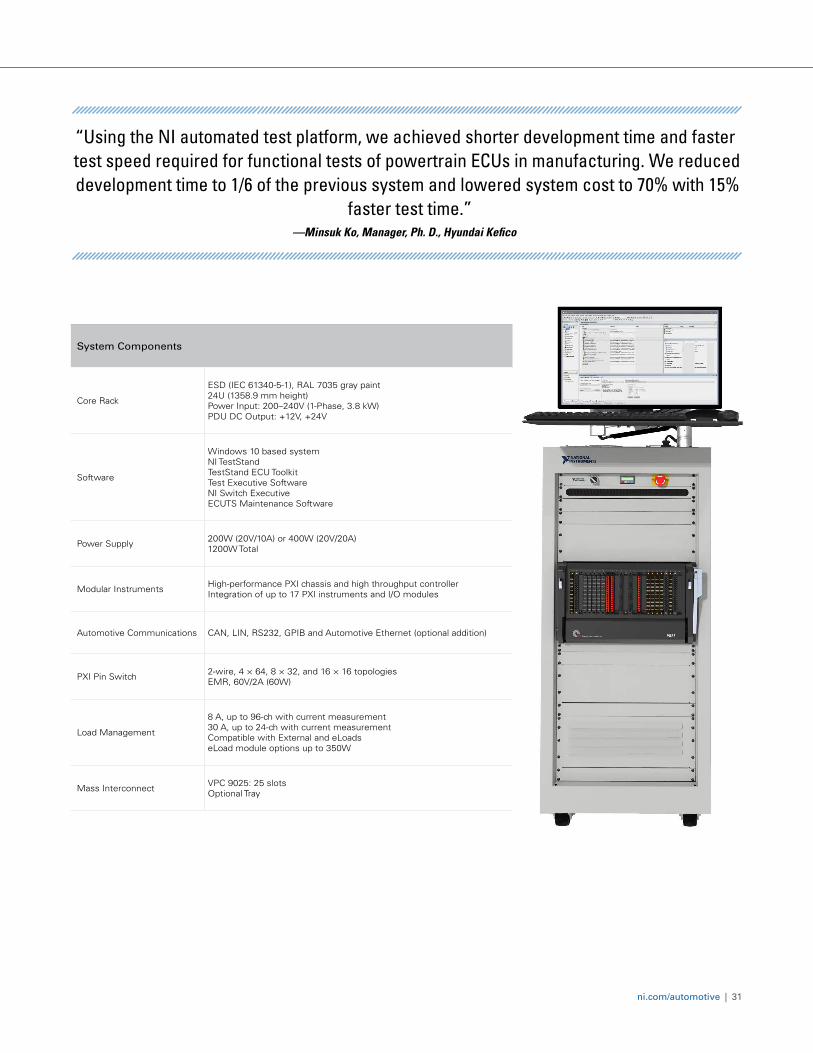
System Components
Core Rack
ESD (IEC 61340-5-1), RAL 7035 gray paint24U (1358.9 mm height)Power Input: 200–240V (1-Phase, 3.8 kW)PDU DC Output: +12V, +24V
Software
Windows 10 based systemNI TestStandTestStand ECU ToolkitTest Executive SoftwareNI Switch ExecutiveECUTS Maintenance Software
Power Supply 200W (20V/10A) or 400W (20V/20A)1200W Total
Modular Instruments High-performance PXI chassis and high throughput controllerIntegration of up to 17 PXI instruments and I/O modules
Automotive Communications CAN, LIN, RS232, GPIB and Automotive Ethernet (optional addition)
PXI Pin Switch 2-wire, 4 × 64, 8 × 32, and 16 × 16 topologiesEMR, 60V/2A (60W)
Load Management
8 A, up to 96-ch with current measurement30 A, up to 24-ch with current measurementCompatible with External and eLoadseLoad module options up to 350W
Mass Interconnect VPC 9025: 25 slots Optional Tray
ni.com/automotive | 31
“Using the NI automated test platform, we achieved shorter development time and faster test speed required for functional tests of powertrain ECUs in manufacturing. We reduced development time to 1/6 of the previous system and lowered system cost to 70% with 15%
faster test time.”—Minsuk Ko, Manager, Ph. D., Hyundai Kefico
Overcome rapidly changing test requirements and innovate with confidence using an open and easily upgradable platform that is designed for test system flexibility.
ni.com/automotive
TEST THE VEHICLESOF TOMORROW TODAY