Embed Size (px)
Citation preview

USER MANUAL
VEGA SERIESAMPLIFIED 12“ SUBWOOFER
VPAS12
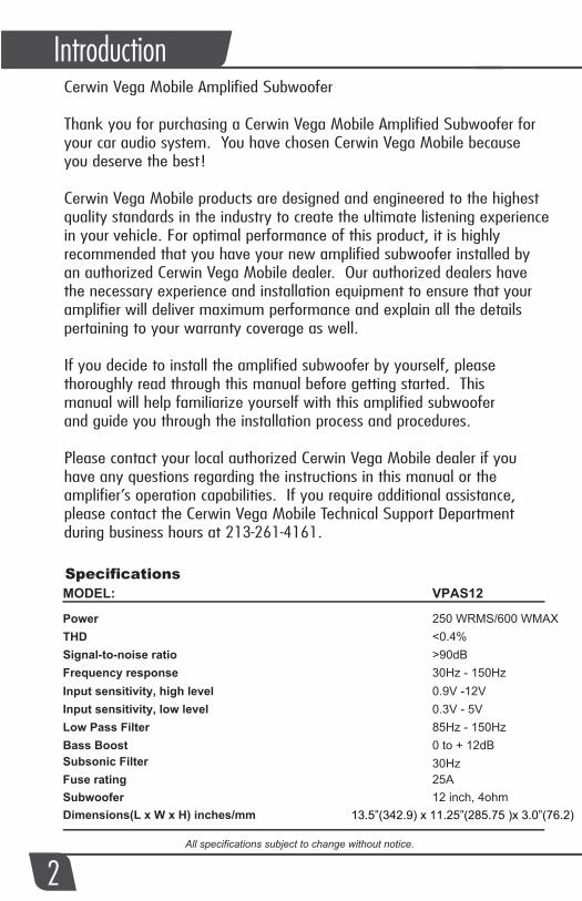
Specifications
All specifications subject to change without notice.
Power THDSignal-to-noise ratioFrequency responseInput sensitivity, high levelInput sensitivity, low levelLow Pass FilterBass BoostSubsonic Filter
Subwoofer 12 inch, 4ohmFuse rating
Dimensions(L x W x H) inches/mm
MODEL:
250 WRMS/600 WMAX<0.4%>90dB30Hz - 150Hz0.9V -12V0.3V - 5V85Hz - 150Hz0 to + 12dB30Hz25A
13.5”(342.9) x 11.25”(285.75 )x 3.0”(76.2)
VPAS12
Cerwin Vega Mobile Amplified Subwoofer
Thank you for purchasing a Cerwin Vega Mobile Amplified Subwoofer for your car audio system. You have chosen Cerwin Vega Mobile because you deserve the best!
Cerwin Vega Mobile products are designed and engineered to the highestquality standards in the industry to create the ultimate listening experiencein your vehicle. For optimal performance of this product, it is highly recommended that you have your new amplified subwoofer installed by an authorized Cerwin Vega Mobile dealer. Our authorized dealers have the necessary experience and installation equipment to ensure that your amplifier will deliver maximum performance and explain all the details pertaining to your warranty coverage as well.
If you decide to install the amplified subwoofer by yourself, please thoroughly read through this manual before getting started. This manual will help familiarize yourself with this amplified subwoofer and guide you through the installation process and procedures.
Please contact your local authorized Cerwin Vega Mobile dealer if you have any questions regarding the instructions in this manual or the amplifier’s operation capabilities. If you require additional assistance, please contact the Cerwin Vega Mobile Technical Support Department during business hours at 213-261-4161.
Check to make sure you have a good ground connection.Check that there is at least 12v on the battery (+) terminal Check that the Remote Input (Turn-On) has at least 10VDC. Check that the green power LED is litCheck all fuse, replace if necessary.Make sure that the Protection LED is not illuminated. If it is lit, shut off the amplifier briefly, and then Power Cycle (reset).
T
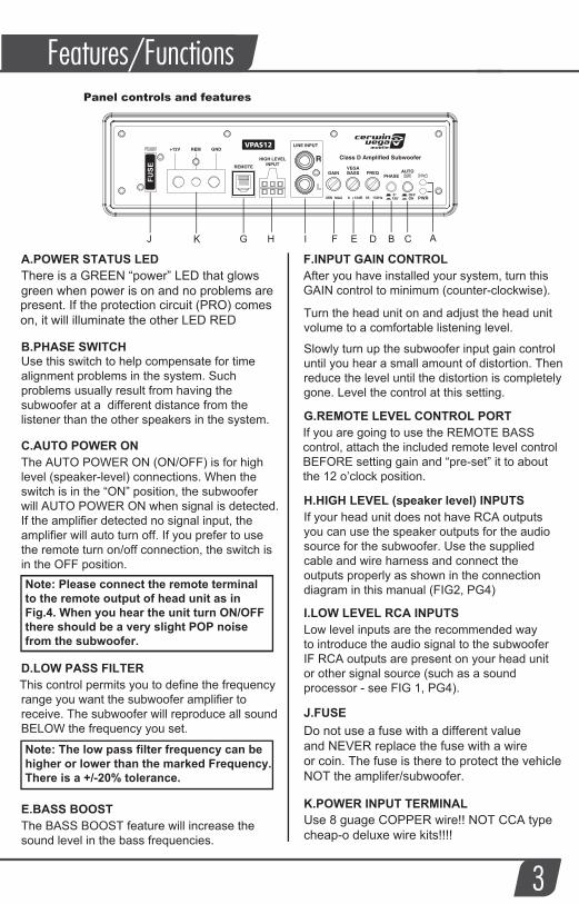
A.POWER STATUS LED
B.PHASE SWITCHUse this switch to help compensate for time alignment problems in the system. Such problems usually result from having the subwoofer at a different distance from the listener than the other speakers in the system.
C.AUTO POWER ONhe AUTO POWER ON (ON/OFF) is for high
level (speaker-level) connections. When the switch is in the “ON” position, the subwooferwill AUTO POWER ON when signal is detected. If the amplifier detected no signal input, the amplifier will auto turn off. If you prefer to use the remote turn on/off connection, the switch is in the OFF position.
D.LOW PASS FILTERThis control permits you to define the frequency range you want the subwoofer amplifier to receive. The subwoofer will reproduce all sound BELOW the frequency you set.
F.INPUT GAIN CONTROLAfter you have installed your system, turn this GAIN control to minimum (counter-clockwise).
Turn the head unit on and adjust the head unit volume to a comfortable listening level.
Slowly turn up the subwoofer input gain control until you hear a small amount of distortion. Then reduce the level until the distortion is completely gone. Level the control at this setting.
G.REMOTE LEVEL CONTROL PORTIf you are going to use the REMOTE BASS control, attach the included remote level control BEFORE setting gain and “pre-set” it to about the 12 o’clock position.
.
H.HIGH LEVEL (speaker level) INPUTSIf your head unit does not have RCA outputsyou can use the speaker outputs for the audiosource for the subwoofer. Use the supplied cable and wire harness and connect the outputs properly as shown in the connectiondiagram in this manual (FIG2, PG4)
I.LOW LEVEL RCA INPUTSLow level inputs are the recommended wayto introduce the audio signal to the subwooferIF RCA outputs are present on your head unitor other signal source (such as a soundprocessor - see FIG 1, PG4).
J.FUSE
K.POWER INPUT TERMINAL
There is a GREEN “power” LED that glows green when power is on and no problems arepresent. If the protection circuit (PRO) comes on, it will illuminate the other LED RED
Do not use a fuse with a different valueand NEVER replace the fuse with a wireor coin. The fuse is there to protect the vehicleNOT the amplifer/subwoofer.
TE.BASS BOOST
he BASS BOOST feature will increase the sound level in the bass frequencies.
Note: Please connect the remote terminal to the remote output of head unit as in Fig.4. When you hear the unit turn ON/OFFthere should be a very slight POP noise from the subwoofer.
Note: The low pass filter frequency can behigher or lower than the marked Frequency.There is a +/-20% tolerance.
Panel controls and features
3
Features/Functions
Use 8 guage COPPER wire!! NOT CCA typecheap-o deluxe wire kits!!!!
This is usually caused by poor quality RCA cables, which can pick up radiated noise. Use only the best quality cables, and route them away from power cables.
Check that the RCA grounds are not shorted to the vehicle chassis Check that the head unit is properly grounded.

Low Level Input WiringLow-level (RCA) input wiring is preferred for best audio performance. Most trunkor hatchback installations will require a 15-20 foot RCA cable, while pickup trucksand under-seat installations will require a 6-12 foot RCA cable. Always use a high quality cable.
NOTE: Do not connect BOTH the high level and low level inputs from yourreceiver to your amplifier at the same time!
High Level Input WiringThe high level input(s) should only be used when your headunit lacks RCA outputs.If the RCA outputs are not present, connect the speaker outputs from the head unitto the high level input connector of the amplifier. Be sure to observe polarity toavoid audio phase problems.
NOTE: Do not connect BOTH the high level and low level inputs from yourreceiver to your amplifier at the same time!
WHITE L+
GREY R+ R- GREY/BLACKL- WHITE/BLACK
To Speaker Terminalsof head unit
Fig.1
Fig.2
ESC
VIEW
BANDSOURCE
AUDIO MUTE FUNC
TAG
From Audio outputs of head unit or signal processor
RemoteLevel Control
4
ESC
VIEW
BANDSOURCE
AUDIO MUTE FUNC
TAG
Installation
SPECIAL NOTE: Always route power and signal seperatly
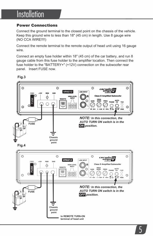
Power ConnectionsConnect the ground terminal to the closest point on the chassis of the vehicle.Keep this ground wire to less than 18" (45 cm) in length. Use 8 gauge wire(NO CCA WIRE!!!!)
Connect the remote terminal to the remote output of head unit using 16 gaugewire.
Connect an empty fuse holder within 18" (45 cm) of the car battery, and run 8 gauge cable from this fuse holder to the amplifier location. Then connect the fuse holder to the "BATTERY+" (+12V) connection on the subwoofer rear panel. Insert FUSE now.
Fig.4
Fig.3
Chassis ground
point
to REMOTE TURN-ONterminal of head unit
NOTE: In this connection, the AUTO TURN ON switch is in the OFF position.
Installation
5
FUSE
FUSE
Chassis ground
point
NOTE: In this connection, the AUTO TURN ON switch is in the ON position.
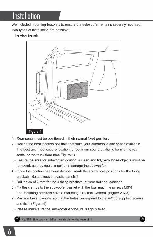
In the trunk
We included mounting brackets to ensure the subwoofer remains securely mounted. Two types of installation are possible.
1 - Rear seats must be positioned in their normal fixed position.2 - Decide the best location possible that suits your automobile and space available. The best and most secure location for optimum sound quality is behind the rear seats, or the trunk floor (see Figure 1).3 - Ensure the area for subwoofer location is clean and tidy. Any loose objects must be removed, as they could knock and damage the subwoofer.4 - Once the location has been decided, mark the screw hole positions for the fixing brackets. Be cautious of plastic panels!!5 - Drill holes of 2 mm for the 4 fixing brackets, at your defined locations.6 - Fix the clamps to the subwoofer basket with the four machine screws M6*8 (the mounting brackets have a mounting direction system). (Figure 2 & 3)7 - Position the subwoofer so that the holes correspond to the M4*25 supplied screws and fix it. (Figure 4)8 - Please make sure the subwoofer enclosure is tightly fixed.
Installation
6
Figure 1
CAUTION!! Make sure to not drill or screw into vital vehicles componets!!!
Installation
7
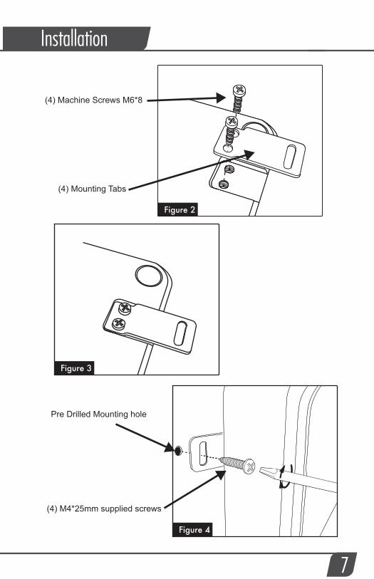
Figure 2
Figure 3
Figure 4
(4) M4*25mm supplied screws
(4) Machine Screws M6*8
(4) Mounting Tabs
Pre Drilled Mounting hole
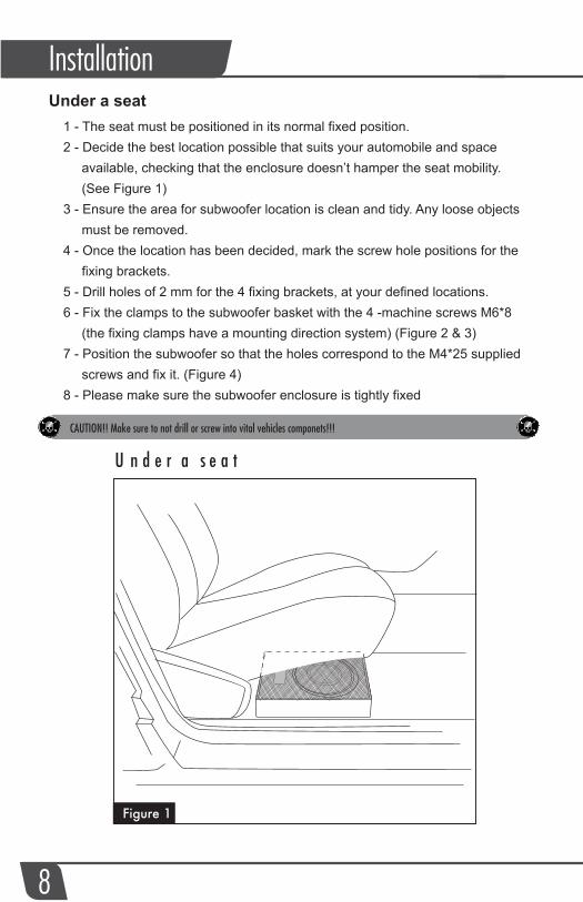
Under a seat
taesarednU
1 - The seat must be positioned in its normal fixed position.2 - Decide the best location possible that suits your automobile and space available, checking that the enclosure doesn’t hamper the seat mobility. (See Figure 1)3 - Ensure the area for subwoofer location is clean and tidy. Any loose objects must be removed.4 - Once the location has been decided, mark the screw hole positions for the fixing brackets.5 - Drill holes of 2 mm for the 4 fixing brackets, at your defined locations.6 - Fix the clamps to the subwoofer basket with the 4 -machine screws M6*8 (the fixing clamps have a mounting direction system) (Figure 2 & 3)7 - Position the subwoofer so that the holes correspond to the M4*25 supplied screws and fix it. (Figure 4)8 - Please make sure the subwoofer enclosure is tightly fixed
Installation
8
Figure 1
CAUTION!! Make sure to not drill or screw into vital vehicles componets!!!
9
Installation
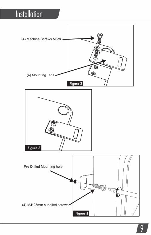
Figure 2
Figure 3
Figure 4
(4) M4*25mm supplied screws
(4) Machine Screws M6*8
(4) Mounting Tabs
Pre Drilled Mounting hole
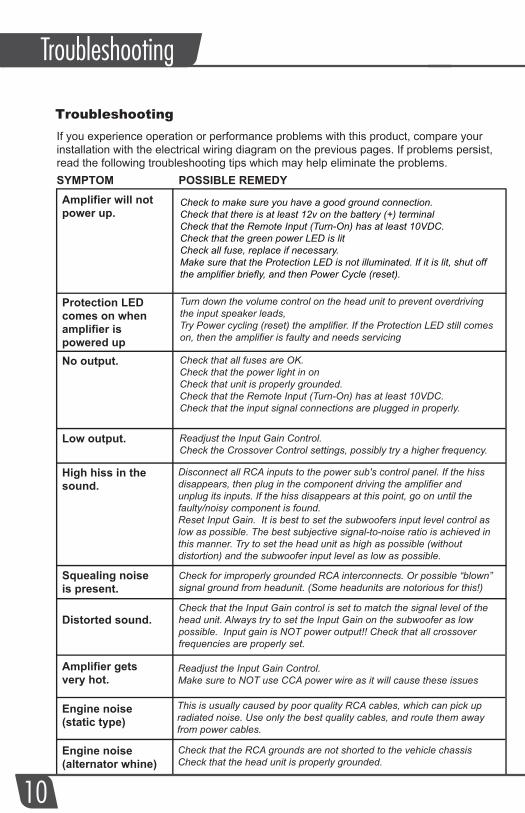
TroubleshootingIf you experience operation or performance problems with this product, compare yourinstallation with the electrical wiring diagram on the previous pages. If problems persist,read the following troubleshooting tips which may help eliminate the problems.
Amplifier will notpower up.
Protection LEDcomes on whenamplifier is powered upNo output.
Low output.
High hiss in thesound.
Squealing noiseis present.
Distorted sound.
Amplifier getsvery hot.
Engine noise(static type)
Engine noise(alternator whine)
SYMPTOM POSSIBLE REMEDY
Check to make sure you have a good ground connection.Check that there is at least 12v on the battery (+) terminal Check that the Remote Input (Turn-On) has at least 10VDC. Check that the green power LED is litCheck all fuse, replace if necessary.Make sure that the Protection LED is not illuminated. If it is lit, shut off the amplifier briefly, and then Power Cycle (reset).
Turn down the volume control on the head unit to prevent overdriving the input speaker leads, Try Power cycling (reset) the amplifier. If the Protection LED still comes on, then the amplifier is faulty and needs servicing
10
Troubleshooting
Check that all fuses are OK.Check that the power light in onCheck that unit is properly grounded.Check that the Remote Input (Turn-On) has at least 10VDC.Check that the input signal connections are plugged in properly.
Readjust the Input Gain Control.Check the Crossover Control settings, possibly try a higher frequency.
Disconnect all RCA inputs to the power sub's control panel. If the hiss disappears, then plug in the component driving the amplifier and unplug its inputs. If the hiss disappears at this point, go on until the faulty/noisy component is found.Reset Input Gain. It is best to set the subwoofers input level control as low as possible. The best subjective signal-to-noise ratio is achieved in this manner. Try to set the head unit as high as possible (without distortion) and the subwoofer input level as low as possible.
Check for improperly grounded RCA interconnects. Or possible “blown” signal ground from headunit. (Some headunits are notorious for this!)
Check that the Input Gain control is set to match the signal level of the head unit. Always try to set the Input Gain on the subwoofer as low possible. Input gain is NOT power output!! Check that all crossover frequencies are properly set.
Readjust the Input Gain Control.Make sure to NOT use CCA power wire as it will cause these issues
This is usually caused by poor quality RCA cables, which can pick up radiated noise. Use only the best quality cables, and route them away from power cables.
Check that the RCA grounds are not shorted to the vehicle chassis Check that the head unit is properly grounded.
Thank you for purchasing a Cerwin Vega Mobile product and we hope to provide you with countless hours of listening enjoyment.
Please take a brief moment to register your new product. By registering your new product, you will receive benefits such as:
- Important product notifications that may pertain to your purchase.- Confirmation and record of ownership in case of loss or theft.- Knowledgeable customer service and technical assistance pertaining to your product.
Register your new product by completely filling out this Product and Warranty Registration card or register online atwww.cerwinvegamobile.com.
Registration is voluntary and failure to register will not diminish your limited warranty rights.
Limited Warranty (U.S.A.)Cerwin Vega Mobile warrants all of our amplifiers and speakers to be free of defects in materials and workmanship for a period of one (1) year.
This warranty is non-transferable and applies only to the original purchaser from an authorized Cerwin Vega Mobile dealer. If service is required and necessary under this warranty due to manufacturing defect or malfunction, then Cerwin Vega Mobile will repair and/or replace defective product with either new or remanufactured like product at no charge at our discretion.
Damage to product caused by the following will not be covered under this warranty: abuse, accident, misuse, neglect, modifications, repairing attempts, seller/installer misrepresentation.
This warranty does not cover any incidental, consequential, or cosmetic damage due to accidents or normal wear and tear, nor does it cover the cost of removing or reinstallation of the product.
Warranty is void if the product’s serial number has been removed, defaced, and/or tampered with.
Warranty Procedure:We recommend that you contact your Cerwin Vega Mobile authorized dealer where your original purchase was made to initiate all warranty claims. Our authorized dealers can guide you through the warranty procedure to ensure that your claim will be processed in a timely manner. All warranty returns must be accompanied with a proof of purchase (a copy of the original sales receipt) and be shipped freight prepaid to our facility with an RA (Return Authorization) number clearly marked on the outside of the package. Direct returns from consumers or non-authorized dealers will be refused if shipped without a valid RA number authorized by Cerwin Vega Mobile beforehand.
INTERNATIONALProducts purchased outside of the U.S.A. are covered only by that country’s distributor and not by Cerwin Vega Mobile U.S.A.
Please Ship All Warranty Claims With Pre-Authorized RA Number To:CV&DA Holdings, Inc.ATTN: Customer Service Department1225 E. 7th St.Los Angeles, CA 90021 USA
Please Contact Customer Service for Further Warranty Information:U.S.A.Tel: 213-261-4161 / Fax: 213-947-4767
11