Embed Size (px)
Citation preview
8/8/2019 Vega handbook
http://slidepdf.com/reader/full/vega-handbook 1/36
8/8/2019 Vega handbook
http://slidepdf.com/reader/full/vega-handbook 2/36
Per Brohäll
THE VEGA HANDBOOK
C o n t e n t s C o n t e n t s
• Forward• Technical Data
• Thoughts behind Vega
• First launching and rigging
• Advice on sailing and sail handling
• Sails and maintenance
• The engine
• Interior and equipment
• Glassfibre and maintenance
• Winter storage and spring commissioning
8/8/2019 Vega handbook
http://slidepdf.com/reader/full/vega-handbook 3/36
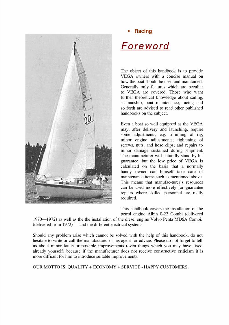
• Racing Foreword Foreword
The object of this handbook is to provide
VEGA owners with a concise manual on
how the boat should be used and maintained.
Generally only features which are peculiar
to VEGA are covered. Those who want
further theoretical knowledge about sailing,
seamanship, boat maintenance, racing and
so forth are advised to read other published
handbooks on the subject.
Even a boat so well equipped as the VEGA
may, after delivery and launching, requiresome adjustments, e.g. trimming of rig;
minor engine adjustments; tightening of
screws, nuts, and hose clips; and repairs to
minor damage sustained during shipment.
The manufacturer will naturally stand by his
guarantee, but the low price of VEGA is
calculated on the basis that a normally
handy owner can himself take care of maintenance items such as mentioned above.
This means that manufac-turer’s resourcescan be used more effectively for guarantee
repairs where skilled personnel are really
required.
This handbook covers the installation of thepetrol engine Albin 0-22 Combi (delivered
1970—1972) as well as the the installation of the diesel engine Volvo Penta MD6A Combi.
(delivered from 1972) — and the different electrical systems.
Should any problem arise which cannot be solved with the help of this handbook, do not
hesitate to write or call the manufacturer or his agent for advice. Please do not forget to tell
us about minor faults or possible improvements (even things which you may have fixed
already yourself) because if the manufacturer does not receive constructive criticism it is
more difficult for him to introduce suitable improvements.
OUR MOTTO IS: QUALITY + ECONOMY + SERVICE = HAPPY CUSTOMERS.
8/8/2019 Vega handbook
http://slidepdf.com/reader/full/vega-handbook 4/36
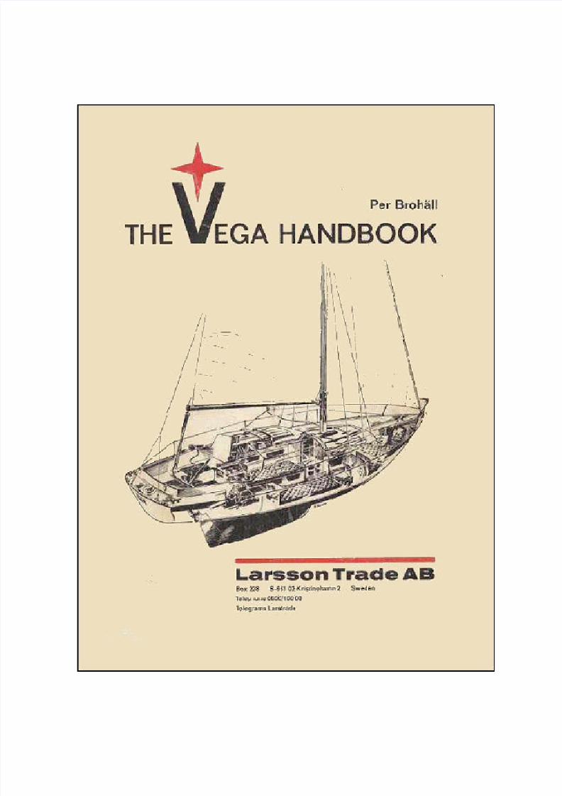
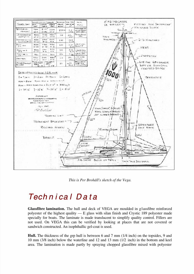
This is Per Brohäll's sketch of the Vega.
Tech n i ca l D a t a Tech n i ca l D a t a
Glassfibre lamination. The hull and deck of VEGA are moulded in g1assfibre reinforced
polyester of the highest quality — E glass with silan finish and Crystic 189 polyester made
specially for boats. The laminate is made translucent to simplify quality control. Fillers are
not used. On VEGA this can be verified by looking at places that are not covered or
sandwich constructed. An isophthallic gel-coat is used.
Hull. The thickness of the grp hull is between 6 and 7 mm (1/4 inch) on the topsides, 9 and
10 mm (3/8 inch) below the waterline and 12 and 13 mm (1/2 inch) in the bottom and keelarea. The lamination is made partly by spraying chopped glassfibre mixed with polyester
8/8/2019 Vega handbook
http://slidepdf.com/reader/full/vega-handbook 5/36
and partly by laying up by hand two layers of woven rovings. The glassfibre content is
approximately 34%. When laying up by hand only, 33% is considered to be satisfactory.
The strength of the laminate depends on the glassfibre content. The hull is stiffened by
glassfibre angles — stringers and ribs — and a fixed floor.
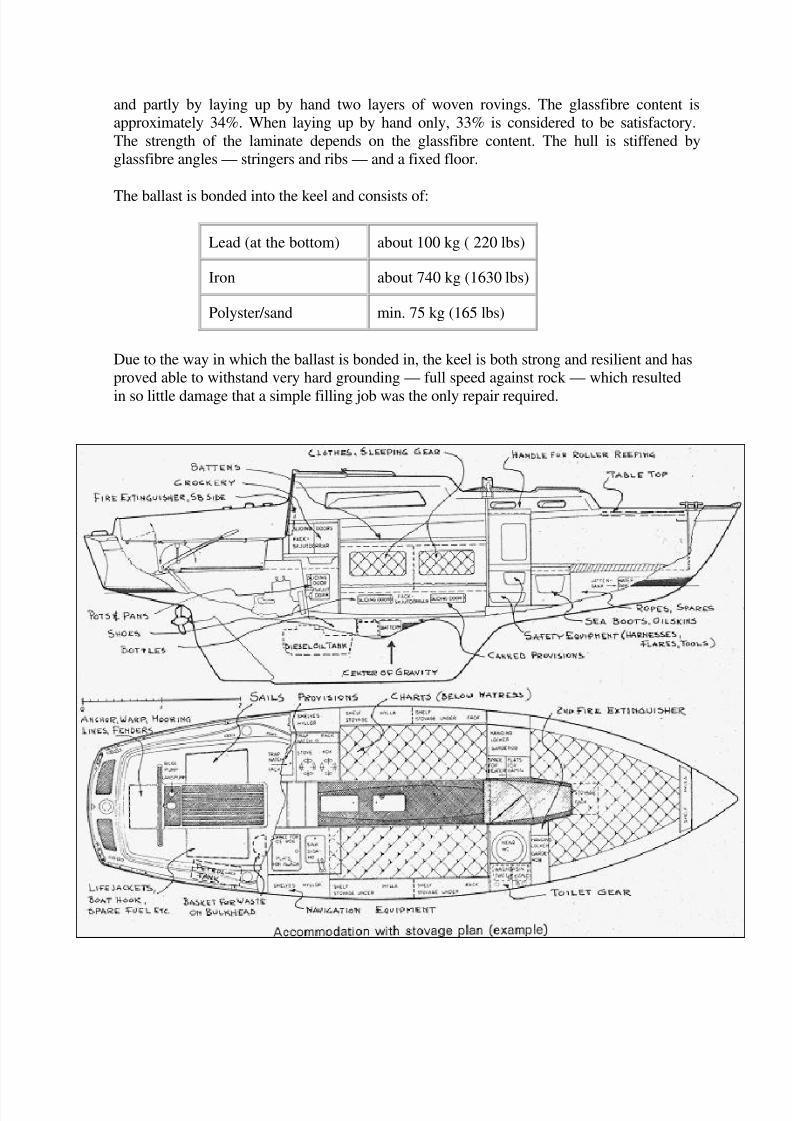
The ballast is bonded into the keel and consists of:
Lead (at the bottom) about 100 kg ( 220 lbs)
Iron about 740 kg (1630 lbs)
Polyster/sand min. 75 kg (165 lbs)
Due to the way in which the ballast is bonded in, the keel is both strong and resilient and has
proved able to withstand very hard grounding — full speed against rock — which resulted
in so little damage that a simple filling job was the only repair required.
8/8/2019 Vega handbook
http://slidepdf.com/reader/full/vega-handbook 6/36
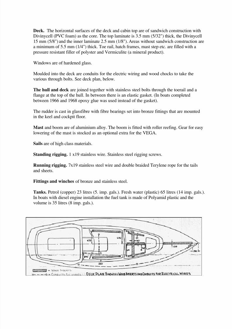
Deck. The horizontal surfaces of the deck and cabin top are of sandwich construction with
Divinycell (PVC foam) as the core. The top laminate is 3.5 mm (5/32") thick, the Divinycell
15 mm (5/8") and the inner laminate 2.5 mm (1/8"). Areas without sandwich construction are
a minimum of 5.5 mm (1/4") thick. Toe rail, hatch frames, mast step etc. are filled with a
pressure resistant filler of polyster and Vermiculite (a mineral product).
Windows are of hardened glass.
Moulded into the deck are conduits for the electric wiring and wood chocks to take thevarious through bolts. See deck plan, below.
The hull and deck are joined together with stainless steel bolts through the toerail and a
flange at the top of the hull. In between there is an elastic gasket. (In boats completed
between 1966 and 1968 epoxy glue was used instead of the gasket).
The rudder is cast in glassfibre with fibre bearings set into bronze fittings that are mounted
in the keel and cockpit floor.
Mast and boom are of aluminium alloy. The boom is fitted with roller reefing. Gear for easy
lowering of the mast is stocked as an optional extra for the VEGA.
Sails are of high class materials.
Standing rigging. 1 x19 stainless wire. Stainless steel rigging screws.
Running rigging. 7x19 stainless steel wire and double braided Terylene rope for the tails
and sheets.
Fittings and winches of bronze and stainless steel.
Tanks. Petrol (copper) 23 litres (5. imp. gals.). Fresh water (plastic) 65 litres (14 imp. gals.).
In boats with diesel engine installation the fuel tank is made of Polyamid plastic and the
volume is 35 litres (8 imp. gals.).

8/8/2019 Vega handbook
http://slidepdf.com/reader/full/vega-handbook 7/36
Th ou g h t s beh i n d VEGATh ou g h t s beh i n d VEGA
The problem in designing a cruising yacht which is economical, comfortable and fast is to
assess all the factors which influence the desired qualities — and to make a successful
compromise.
Eco n o m y Eco n o m y
A light boat is economical. Not so long ago, light and strong designs were expensive tomake. With modern glassfibre construction it is possible to make light and strong mouldings
at almost the same price per pound as heavy mouldings. The price per pound of a complete
sailing yacht is just a fraction higher for a light boat than a heavy boat. Consequently it is
possible today to build a roomy boat which is light in relation to the volume — giving more
boat for the money. Naturally, the yacht has to be designed for modern, industrial
manufacture. From the designer’s point of view, disregarding the manufacturer’s industrial
and selling efficiency, these are the most important factors to achieve to ensure a low initial
price.
However, the annual cost is almost as important for the owner. Upkeep, yard bills and the
cost of sails etc are almost directly proportional to the weight of the yacht (displacement).
C o m f o r t C o m f o r t
A comfortable boat is one which is easy to handle, a pleasure to own and, above all, roomy.
Comfort is more dependent on "elbow room" and standing headroom than on ingenious
accommodation and equipment details. Thus a large volume is desirable.
If the boat is light she will be easy to handle because there will be small weights to handle
and small sails will be carried in relation to the size.
A very common opinion is that a stiff hull has a quicker motion at sea than a less stiff hull.
In small sailing yachts the steadying effect of the sails makes this a purely academic
opinion. Long experience of sailing in the open sea has taught me that there is almost no
difference in the sea kindliness of a light, stiff boat and that of a heavy, narrow boat. There
is so much power in the seas that they can give large sailing vessels a rather quick motionregardless of the hull shape. Furthermore, it is more comfortable to sail at a small angle of
heel and in a boat which does not ship a lot of water. More important than the athwartships
motion is the longitudinal motion if the boat pounds heavily. Comparing the VEGA in a test
with a much heavier offshore cruiser of a well known type, showed that the latter poundedmuch more and shipped more water at the same speed. The only boat which has been sailed
single handed twice round the world, "Islander" sailed by Pidgeon, had a very stiff, hard
chine hull. My conclusions are that for normal cruising — often in sheltered waters —a
light, stiff boat is as good or better than a heavier boat. Catamarans are the ultimate in this
direction; they have been used for long ocean passages but there are other problems - which
is another story.
8/8/2019 Vega handbook
http://slidepdf.com/reader/full/vega-handbook 8/36
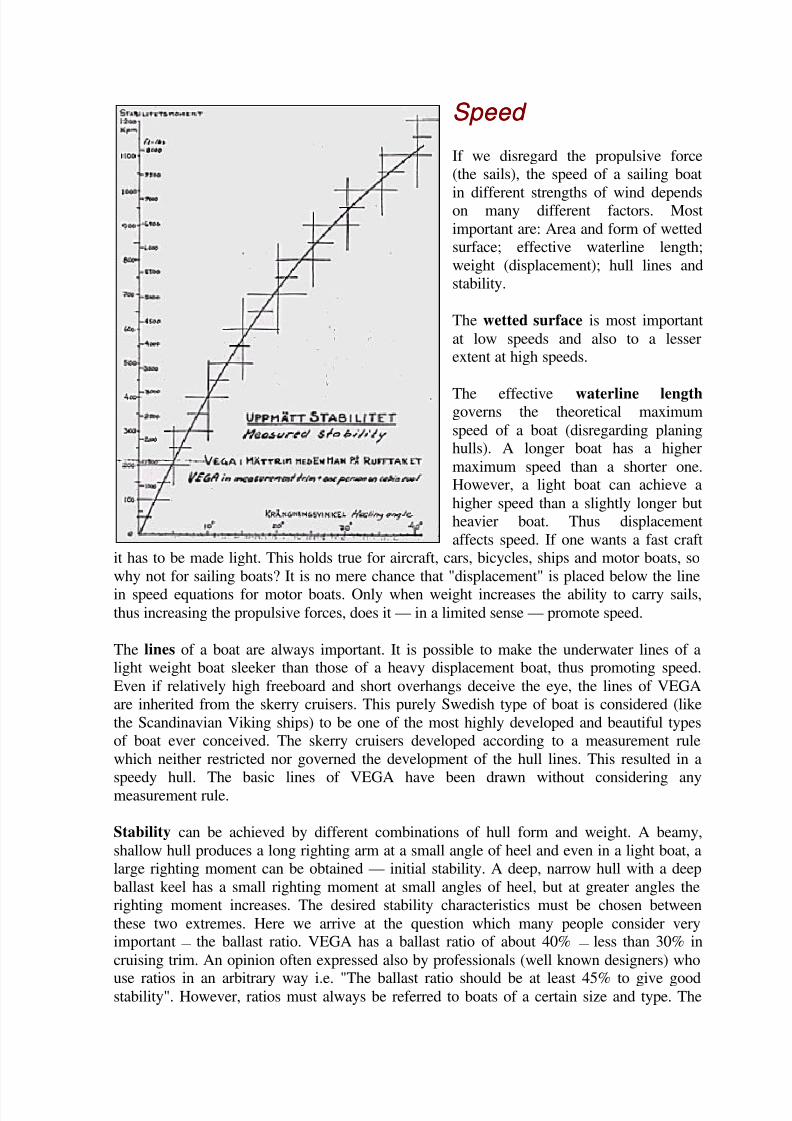
Speed Speed
If we disregard the propulsive force
(the sails), the speed of a sailing boat
in different strengths of wind dependson many different factors. Most
important are: Area and form of wetted
surface; effective waterline length;
weight (displacement); hull lines and
stability.
The wetted surface is most important
at low speeds and also to a lesserextent at high speeds.
The effective waterline length governs the theoretical maximum
speed of a boat (disregarding planinghulls). A longer boat has a higher
maximum speed than a shorter one.However, a light boat can achieve a
higher speed than a slightly longer but
heavier boat. Thus displacement
affects speed. If one wants a fast craft
it has to be made light. This holds true for aircraft, cars, bicycles, ships and motor boats, so
why not for sailing boats? It is no mere chance that "displacement" is placed below the line
in speed equations for motor boats. Only when weight increases the ability to carry sails,thus increasing the propulsive forces, does it — in a limited sense — promote speed.
The lines of a boat are always important. It is possible to make the underwater lines of alight weight boat sleeker than those of a heavy displacement boat, thus promoting speed.
Even if relatively high freeboard and short overhangs deceive the eye, the lines of VEGA
are inherited from the skerry cruisers. This purely Swedish type of boat is considered (like
the Scandinavian Viking ships) to be one of the most highly developed and beautiful types
of boat ever conceived. The skerry cruisers developed according to a measurement rule
which neither restricted nor governed the development of the hull lines. This resulted in a
speedy hull. The basic lines of VEGA have been drawn without considering any
measurement rule.
Stability can be achieved by different combinations of hull form and weight. A beamy,
shallow hull produces a long righting arm at a small angle of heel and even in a light boat, a
large righting moment can be obtained — initial stability. A deep, narrow hull with a deep
ballast keel has a small righting moment at small angles of heel, but at greater angles the
righting moment increases. The desired stability characteristics must be chosen between
these two extremes. Here we arrive at the question which many people consider veryimportant — the ballast ratio. VEGA has a ballast ratio of about 40% — less than 30% in
cruising trim. An opinion often expressed also by professionals (well known designers) who
use ratios in an arbitrary way i.e. "The ballast ratio should be at least 45% to give goodstability". However, ratios must always be referred to boats of a certain size and type. The
8/8/2019 Vega handbook
http://slidepdf.com/reader/full/vega-handbook 9/36
ballast ratio is not sacred. The old English cutters had a ballast ratio of 60 to 70% (lead
mines!) and were narrow, heavy and tender, and sailed at a large angle of heel. The other
extreme, multihulls, have a ballast ratio of 0 and sail at a very much sma!ler angle of heel.
VEGA has been designed with a stiff hull form so that the ballast weight can be kept as low
as possible to achieve the necessary righting moment required in the case of a completecapsize. More ballast would make VEGA slower in most conditions — and more expensive.The measured stability of the VEGA (almost empty) is shown above. With cruising
equipment and crew the stability is increased considerably. In light displacement boatspayload — crew, provisions. equipment etc — is much greater in relation to the weight of the
boat than is the case in heavier boats. Thus a light boat is much more sensitive to the
payload. If such a boat were ballasted to obtain the maximum stability (ability to carry full
canvas in winds of 10 to 14 knots) when empty, with a full cruising load it would have
excessive stability and be slow. This is why the weight of the ballast keel in VEGA has been
calculated to provide the correct stability in cruising trim. If, however, for family sailing,
more stability is required, VEGA can be loaded with heavy cruising equipment but
performance will suffer. Owners who boast of their stiff boats, capable of carrying fullcanvas in a 20 knot wind are stating either that the boat is.under canvassed and is slow in
light winds or that they do not understand that a boat sails much more efficiently and fasterat a small angle of heel. Heeling more than 35 degrees is always a disadvantage and few
boats sail efficiently when heeling more than 30 degrees. Light, shallow boats like VEGA
should be sailed on the wind with not more than 20 to 25 degrees of heel. This means
comfortable, dry sailing in fresh winds and a heavy sea. The sail area must be reduced in
good time thus giving better speed. VEGA can certainly stand up to full canvas in a 20 knot
wind but comfort and speed are sacrificed.
Now we can return to stability and ballast. Some owners have requested more ballast or a
change from iron to lead. Because VEGA is meant to be a strict one-design class the
builders have no intention of making such alterations. Let us look a little closer at theproblems to show that the suggested alterations are not really justified.
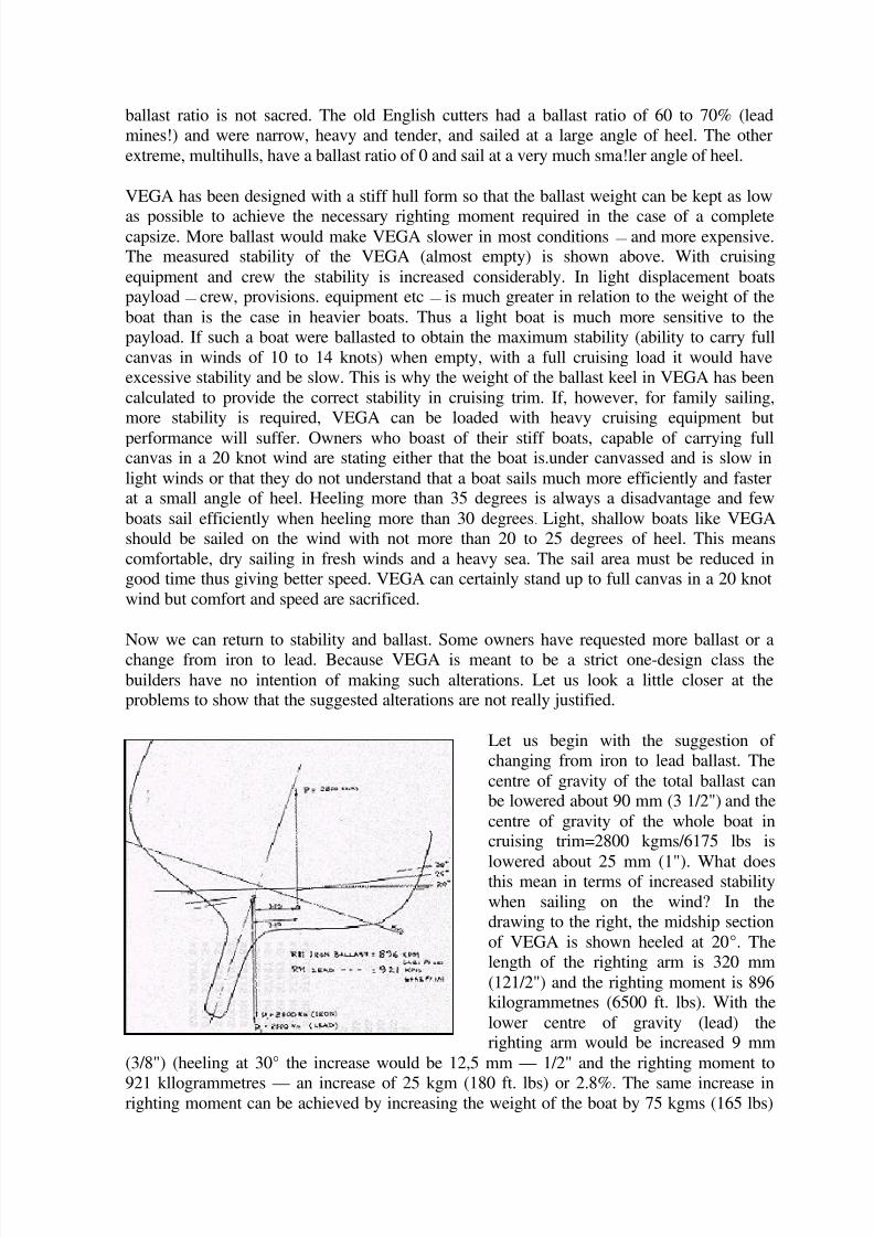
Let us begin with the suggestion of
changing from iron to lead ballast. The
centre of gravity of the total ballast canbe lowered about 90 mm (3 1/2") and the
centre of gravity of the whole boat incruising trim=2800 kgms/6175 lbs is
lowered about 25 mm (1"). What doesthis mean in terms of increased stability
when sailing on the wind? In the
drawing to the right, the midship section
of VEGA is shown heeled at 20°. The
length of the righting arm is 320 mm
(121/2") and the righting moment is 896kilogrammetnes (6500 ft. lbs). With the
lower centre of gravity (lead) therighting arm would be increased 9 mm
(3/8") (heeling at 30° the increase would be 12,5 mm — 1/2" and the righting moment to
921 kllogrammetres — an increase of 25 kgm (180 ft. lbs) or 2.8%. The same increase inrighting moment can be achieved by increasing the weight of the boat by 75 kgms (165 lbs)
8/8/2019 Vega handbook
http://slidepdf.com/reader/full/vega-handbook 10/36
or by moving one person weighing 80 kgms (176 lbs) a distance of 310 mm (1 ft.) to
windward. It is obvious that placing the ballast deep down is of little importance at the
modest angle of heel at which VEGA sails most efficiently. The figure also shows that the
increased angle of heel puts the lateral plane in the, shadow of the hull and so reduces its
efficiency:
The other suggestion — increased ballast weight — could be justified in waters where theaverage wind strength is more than 10 to 12 knots and the direction such that much of the
sailing time is spent on the wind. However, what is said above shows that the requiredincrease in stability can be achieved by not being weight conscious when equipping the boat
and possibly by using internal ballast. In this way the one-design theme is maintained and it
is always possible to lighten the boat to increase the speed for racing — especially in light
winds.
Summing up, Lightness has been the main consideration behind the design of VEGA. A
light boat can be made roomy and fast in relation to size and price.
To make VEGA the best possible family boat a little speed had to be sacrified. A powerful
and heavy engine and good equipment with tanks, pulpits and a comfortable interior adds
weight. The sail plan had to be drawn with an eye on both family sailing and racing. For
pure racing a smaller mainsail and a larger foretriangle would be worth while, but be less
handy and more expensive. For one design racing — VEGA against VEGA — the rating
naturally has no importance. In 1969 22 VEGA’s started as a separate class in Sweden’s
largest offshore race (Round Gotland). That was One Design Offshore Racing for the firsttime.
A compromise, and every boat is a compromise — cannot give everything, but happy
owners consider the VEGA to be an ideal family boat. Racing results show that a well tunedVEGA with a good crew can win handicap races sailed to the R.O.R.C. and C.C.A.
measurement rules and other simpler rules. The compromise seems to be a good one.
8/8/2019 Vega handbook
http://slidepdf.com/reader/full/vega-handbook 11/36
Fi r st l a u n ch i n g a n d r i g g i n g Fi r st l a u n ch i n g a n d r i g g i n g
L a u n c h i n g L a u n c h i n g VEGA is delivered in a shipping cradle which has been with the boat since she was built. A
steel band is fixed through the lower rudder fitting with an ordinary steel bolt to hold the
back of the keel to the cradle.
The recommended launching procedure is as follows:
1. Remove the bolt that holds the steel band. Replace it with the stainless steel bolt that
is fixed to the aft end of the cradle. The bolt should be tightened with a patentwrench (14 mm).
2. Lifting strops should be put in front of the keel and the other behind. Attach the
strops to the hook of the crane. When the strops are tight they should be adjusted so
that they do not bear against any sharp angles.
3. Put fenders on the side of the boat which will be alongside the dock and attach long
mooring lines fore and aft. These are used to control the boat when it is lifted.
4. Check:
o that the bottom plug is tight,
o that the cooling water seacock for the engine is open,
o that the valves for cooling water are closed. These are situated one on the
cooling water pump, the second on the port side of the cylinder block and the
thind on the exhaust pipe.
5. Close the sea cocks for the toilet and sink to prevent any risk of leakage when the
boat is launched. When in the water open and check that the hose clamps are tight.6. Lift the boat until it is well clear of the cradle.
7. The unpainted parts where the boat has been resting on the cradle should be paintedwith the bottom paint provided for the purpose.
8. Lift and launch the boat.
9. Unhook one part of each strop and recover the strops with the crane.
If the boat cannot be rigged where she is launched it is best to move to a mast crane where
you can work in peace and quiet. The mast can be loaded on to the cabin top and pulpit andsecured. The engine is test run before delivery and there is fuel in the tank for about one
hour’s running. Check the level in the battery and the oil level in the engine — in addition to
the checks mentioned in paragraph 4 above. Top up with fuel as soon as possible. Follow
the engine instructions when starting the engine.
8/8/2019 Vega handbook
http://slidepdf.com/reader/full/vega-handbook 12/36
R i g g i n g : R i g g i n g :
The standing and running rigging are packed in the
boat and marked. The rigging procedure is as follows:
1. Place the mast on two boxes or trestles.
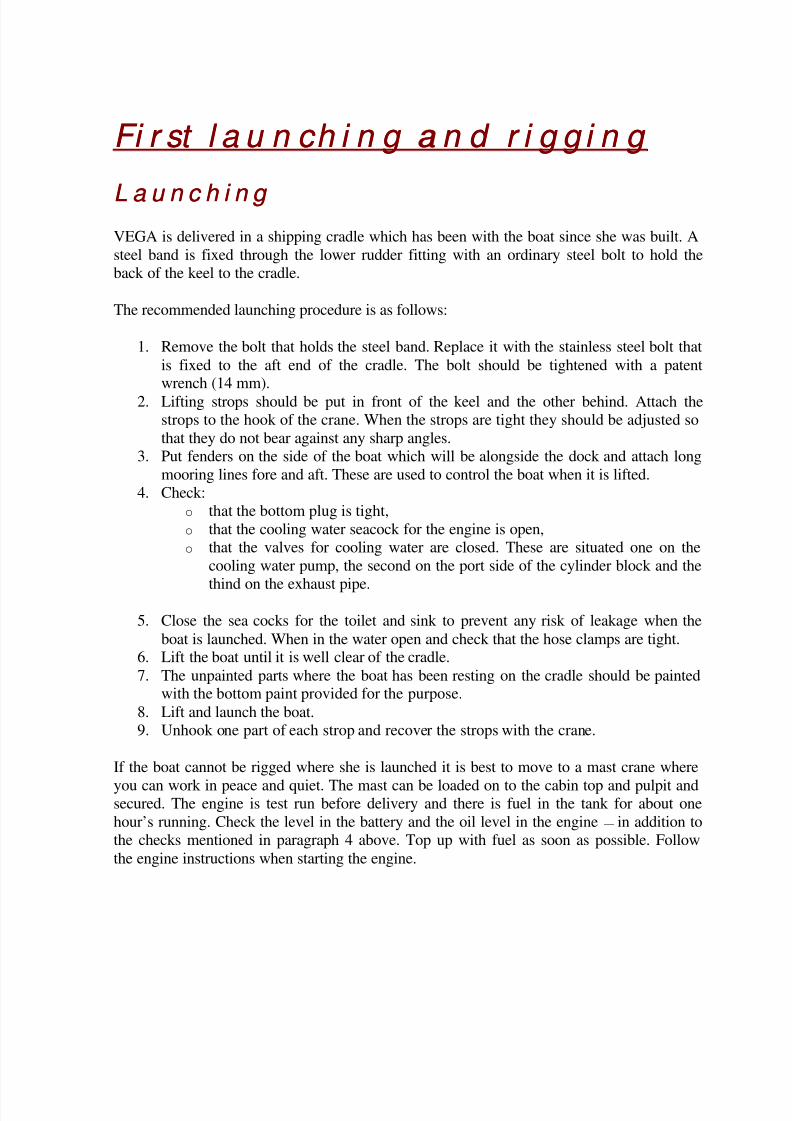
2. The soft eye on the jib halyard — the other end
carries a snap shackle — is put over the sheaves at
the top of the mast on the same side as the jib
halyard winch with the soft eye on the aft side. The
rope tail is then attached to the wire halyard so that the two form a reef knot.
3. The eye of the main halyard is fed over the sheaves on the other side of the mast head and
the rope tail is attached as on the jib halyard. In this instance the rope tail is on the forwardside of the mast.
4. The forward and aft lower shrouds are fixed
to their respective tangs.5. The main shrouds are attached.
6. The forestay is attached to the aft hole on
the forward side of the mast head fitting.
The forward hole is for the spinnaker
halyard block.
7. The block for the topping lift is fixed to the
inner hole on the aft side of the mast. The block should be turned so that the rope end leadsdown the mast.
8. The back stay is fixed in the aft hole.
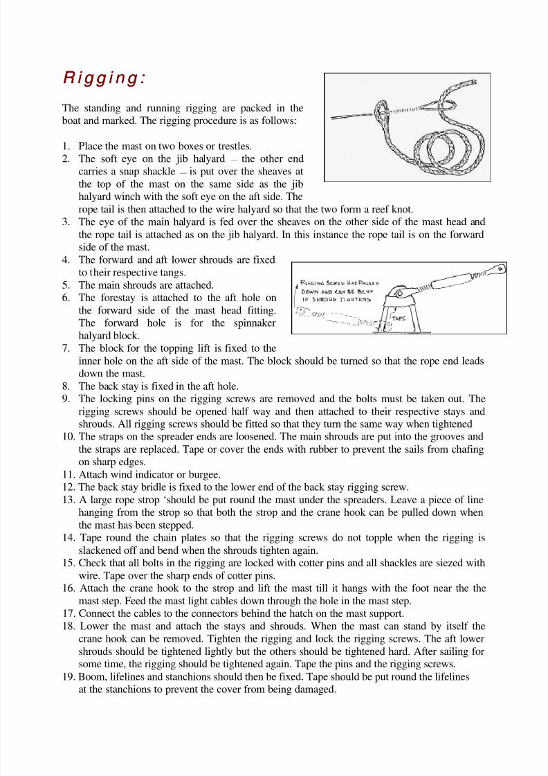
9. The locking pins on the rigging screws are removed and the bolts must be taken out. The
rigging screws should be opened half way and then attached to their respective stays andshrouds. All rigging screws should be fitted so that they turn the same way when tightened
10. The straps on the spreader ends are loosened. The main shrouds are put into the grooves and
the straps are replaced. Tape or cover the ends with rubber to prevent the sails from chafing
on sharp edges.
11. Attach wind indicator or burgee.
12. The back stay bridle is fixed to the lower end of the back stay rigging screw.
13. A large rope strop ‘should be put round the mast under the spreaders. Leave a piece of line
hanging from the strop so that both the strop and the crane hook can be pulled down when
the mast has been stepped.14. Tape round the chain plates so that the rigging screws do not topple when the rigging is
slackened off and bend when the shrouds tighten again.
15. Check that all bolts in the rigging are locked with cotter pins and all shackles are siezed with
wire. Tape over the sharp ends of cotter pins.
16. Attach the crane hook to the strop and lift the mast till it hangs with the foot near the the
mast step. Feed the mast light cables down through the hole in the mast step.
17. Connect the cables to the connectors behind the hatch on the mast support.
18. Lower the mast and attach the stays and shrouds. When the mast can stand by itself the
crane hook can be removed. Tighten the rigging and lock the rigging screws. The aft lower
shrouds should be tightened lightly but the others should be tightened hard. After sailing forsome time, the rigging should be tightened again. Tape the pins and the rigging screws.
19. Boom, lifelines and stanchions should then be fixed. Tape should be put round the lifelinesat the stanchions to prevent the cover from being damaged.
8/8/2019 Vega handbook
http://slidepdf.com/reader/full/vega-handbook 13/36
Ad vi ce on sa i l i n g a n d sa i l h a n d l i n g Ad vi ce on sa i l i n g a n d sa i l h a n d l i n g
Set t i n g sa i l s fo r t h e f i r st sa i l Set t i n g sa i l s f or t h e f i r st sa i l
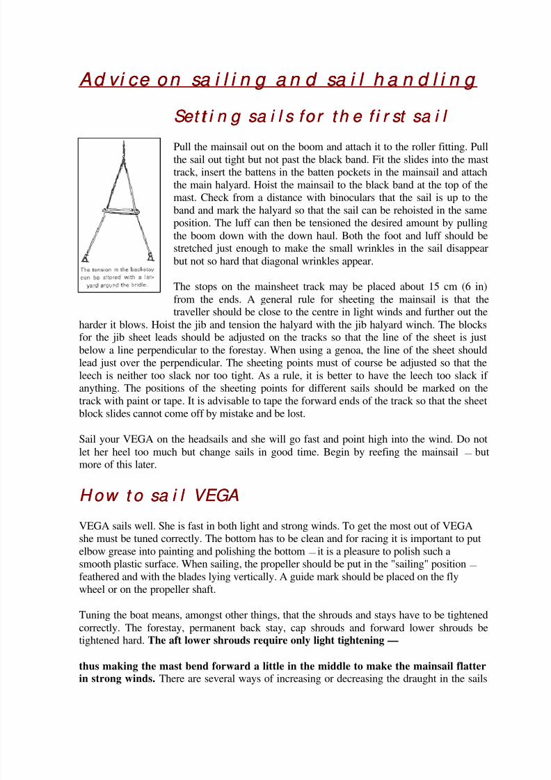
Pull the mainsail out on the boom and attach it to the roller fitting. Pull
the sail out tight but not past the black band. Fit the slides into the mast
track, insert the battens in the batten pockets in the mainsail and attach
the main halyard. Hoist the mainsail to the black band at the top of the
mast. Check from a distance with binoculars that the sail is up to the
band and mark the halyard so that the sail can be rehoisted in the same
position. The luff can then be tensioned the desired amount by pulling
the boom down with the down haul. Both the foot and luff should bestretched just enough to make the small wrinkles in the sail disappear
but not so hard that diagonal wrinkles appear.
The stops on the mainsheet track may be placed about 15 cm (6 in)
from the ends. A general rule for sheeting the mainsail is that thetraveller should be close to the centre in light winds and further out the
harder it blows. Hoist the jib and tension the halyard with the jib halyard winch. The blocksfor the jib sheet leads should be adjusted on the tracks so that the line of the sheet is just
below a line perpendicular to the forestay. When using a genoa, the line of the sheet should
lead just over the perpendicular. The sheeting points must of course be adjusted so that the
leech is neither too slack nor too tight. As a rule, it is better to have the leech too slack if
anything. The positions of the sheeting points for different sails should be marked on the
track with paint or tape. It is advisable to tape the forward ends of the track so that the sheet
block slides cannot come off by mistake and be lost.
Sail your VEGA on the headsails and she will go fast and point high into the wind. Do not
let her heel too much but change sails in good time. Begin by reefing the mainsail — butmore of this later.
H ow t o sa i l VEGAH ow t o sa i l VEGA
VEGA sails well. She is fast in both light and strong winds. To get the most out of VEGA
she must be tuned correctly. The bottom has to be clean and for racing it is important to put
elbow grease into painting and polishing the bottom — it is a pleasure to polish such a
smooth plastic surface. When sailing, the propeller should be put in the "sailing" position —
feathered and with the blades lying vertically. A guide mark should be placed on the fly
wheel or on the propeller shaft.
Tuning the boat means, amongst other things, that the shrouds and stays have to be tightened
correctly. The forestay, permanent back stay, cap shrouds and forward lower shrouds betightened hard. The aft lower shrouds require only light tightening —
thus making the mast bend forward a little in the middle to make the mainsail flatter
in strong winds. There are several ways of increasing or decreasing the draught in the sails
8/8/2019 Vega handbook
http://slidepdf.com/reader/full/vega-handbook 14/36
by bending the mast or adjusting the tension on the stays, but before trying these the advice
of an experienced sailor should be sought.
Tuning includes ascertaining the correct position on the track for the sheet leads for different
sails in different wind strengths. Also different lengths of tack pennant may be needed.
Shackles, snap shackles, sheet track and winches have to be adjusted and oiled to functionsmoothly and fast. Tuning, in a wider sense, means marrying sails to spars and rigging andgetting everything, including the crew to function fast and with precision.
VEGA is well balanced and has just the right feel on the helm when sailed with the correct
sails. A slight tendency to luff, and thus a pressure on the helm, is desirable in a boat with aconventional keel and rudder in order to get the boat to go well to windward. When the
breeze freshens, the pressure on the rudder increases. To keep the pressure low, the first
large reduction in sail area is best made by reefing the mainsail. Another reason is that the
headsails are more efficient than the mainsail size for size. Just like other boats, VEGA can
become very hard on the helm under certain conditions. When broad reaching with the
spinnaker pole against the forestay in a 16 to 20 knot wind, considerable effort may beneeded to keep the boat on course — but then she travels at over 10 knots for periods, well
above her theoretical maximum speed. If the wind increases, the spinnaker has to bechanged for a genoa jib and the boat will again be very easy to handle. When running, the
spinnaker can possibly be used in up to 30 knots of wind — giving a sensationally fast run.
VEGA can be sailed under either mainsail or jib alone. Under jib she is more easily
manoeuvred than under mainsail only. With reefed storm jib (area 5,4 m2 /58 sq ft) she has
been sailed to windward in heavy seas and a 38 knot wind. It was possible to tack if the right
moment was shosen. Later, under the same conditions, VEGA broad reached for severalhours at a mean speed of 4 knots. Certainly very fast for a boat of her size with a sail area of
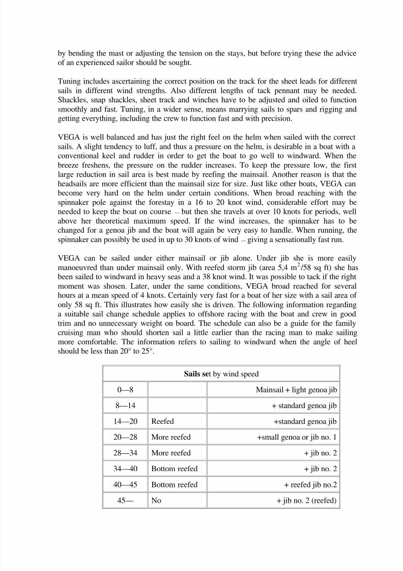
only 58 sq ft. This illustrates how easily she is driven. The following information regarding
a suitable sail change schedule applies to offshore racing with the boat and crew in good
trim and no unnecessary weight on board. The schedule can also be a guide for the family
cruising man who should shorten sail a little earlier than the racing man to make sailing
more comfortable. The information refers to sailing to windward when the angle of heel
should be less than 20° to 25°.
Sails set by wind speed
0—8 Mainsail + light genoa jib
8—14 + standard genoa jib
14—20 Reefed +standard genoa jib
20—28 More reefed +small genoa or jib no. 1
28—34 More reefed + jib no. 2
34—40 Bottom reefed + jib no. 2
40—45 Bottom reefed + reefed jib no.2
45— No + jib no. 2 (reefed)
8/8/2019 Vega handbook
http://slidepdf.com/reader/full/vega-handbook 15/36
When racing it is important to keep the boat light. The amount of food and stores (water and
fuel) has to be considered and maybe part of the cruising equipment can be left ashore.
Sa i l h a n d l i n g Sa i l h a n d l i n g
It is best to practice setting, changing and taking down sails in light conditions. Once the
procedure is known and after some practice, sail changes can easily be effected in strong
winds, large seas, rain and darkness. There are many ways in which sails can be worked and
handled and it is best to determine which way is best suited to oneself and the crew. The
following are brief suggestions on different methods:
Ch a n g i n g o f h ea d sa i l s Ch a n g i n g o f h ea d sa i l s
The fore deck hand does everything except sheeting the sail home, which should be done by
the crew man in the cockpit or by the helmsman.
1. The tack of the new sail is attached to the stem head — at least two hooks should be
fixed on the stem head fitting.2. The lower sail hanks of the old sail should be taken off the forestay.
3. The new sail is hanked on and pulled out along the lee rail.
4. A new sheet is attached — this means having two sets of sheets and sheet leads.
5. The old sail is taken down and unhanked:
6. The halyard is transfered to the new sail — and also the sheets, if two sets are not
available.
7. The new sail is hoisted and sheeted in.
8. The tack of the old sail is unhooked and the sail taken below.
Reef i n g t h e m a i n sa i l Reef i n g t h e m a i n sa i l
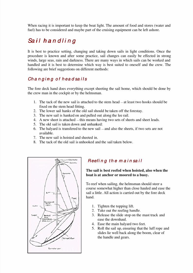
The sail is best reefed when hoisted, also when the
boat is at anchor or moored to a buoy.
To reef when sailing, the helmsman should steer acourse somewhat higher than close hauled and ease the
sail a little. All action is carried out by the fore deck hand.
1. Tighten the topping lift.2. Take out the reefing handle.
3. Release the slide stop on the mast track andease the downhaul.
4. Ease the main halyard two feet.
5. Roll the sail up, ensuring that the luff rope and
slides lie well back along the boom, clear of
the handle and gears.
8/8/2019 Vega handbook
http://slidepdf.com/reader/full/vega-handbook 16/36
6. If more reduction in sail area is required, ease the main halyard again and continue
rolling.
7. The sail should be rolled so that the boom lies above the level of the black band on
the mast and does not droop too much. The slides should be removed from the lower
part of the mast track as any left in will pull the sail out of shape.
8. Tighten the downhaul, ease the topping lift, and sheet in the sail.
When rolling it may be necessary to pull the sail out along the boom to ensure that it stows
neatly. When taking in a large reef, it may be necessary to remove the bottom batten if itdoes not lie parallel to the boom. The reef can be improved, the boom prevented from
drooping and the sail prevented from wrinkling if some form of padding is wrapped in the
sail from the middle to the end of the boom. A sail bag, a pillow or some spare battens are
suitable.
Sa i l i n g w i t h t h e spi n n a k er Sa i l i n g w i t h t h e spi n n a k er
The standard VEGA must be equipped with the following extras to take a spinnaker:Spinnaker, spinnaker boom, boom topping lift with an extra block on the mast, foreguy
(downhaul) with a block on the fore deck or by the mast, halyard with a block at the top of
the mast above the forestay, two sheets, two sheet blocks. Your VEGA already has mast
track with a traveller for the spinnaker koom and fittings for blocks at the stern. (See figure,
below).
H o w t o set a spi n n a k er H o w t o set a spi n n a k er
Only in light winds can the spinnaker be set and taken down with only two men on deck.
Normally there should be three. The foreguy, sheet and after guy can be handled from thecockpit. Everything else must be handled by the fore deck hand.
1. Bag the spinnaker but let the clews and the head stick out of the bag.
2. Place the bag on the leeward side of the foredeck and secure it with a length of line.
3. Pull the guy (windward sheet) outside the windward shrouds and round the forestayand hook it to the lifeline for the time being. Pull the leeward sheet outside the
shrouds and fix it beside the guy.4. Pull the fore guy through the block on the foredeck and take it to a cleat in the
cockpit.
5. Attach the spinnaker boom to the traveller on the mast track and place the forward
end on deck to windward of the forestay.
6. Hook the topping lift and the foreguy on to the pole.
7. Raise the pole until it is horizontal and take up the slack on the foreguy.
8. Attach the guy and the sheet to the clews of the spinnaker and take up the slack In
them. Put the guy through the end of the pole.9. Attach the halyard with a bowline.
10. Hoist the spinnaker under and behind the genoa as fast as possible. Do not sheet thesail until the halyard is secured.
11. Take up on the guy until the tack of the sail reaches the pole end and continue
hauling until the pole is at right angles to the direction of the apparent wind. (Watch
you wind indicator or burgee). The foreguy may have to be eased.12. Take up on the sheet until the sail fills and no more.
8/8/2019 Vega handbook
http://slidepdf.com/reader/full/vega-handbook 17/36
13. Adjust the position of the pole on the mast so that the pole is perpendicular to the
mast. The downhaul may need easing and the topping lift tightening.
14. Drop the genoa and secure it on deck.
R u l es t o m em o r i se R u l es t o m em o r i se
1. Keep the pole at right angles to the apparent wind.2. Keep the pole perpendicular to the mast.
3. The end of the pole should be the same height above the water as the clew of the
spinnaker.
4. The sail should be sheeted no more than necessary to keep it full.
5. Jerk the sheet if the luff starts falling in.
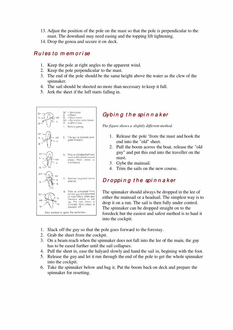
Gyb i n g t h e spi n n a k er Gyb i n g t h e spi n n a k er
The figure shows a slightly different method.
1. Release the pole ‘from the mast and hook the
end into the "old" sheet.2. Pull the boom across the boat, release the "old
guy" and put this end into the traveller on the
mast.
3. Gybe the mainsail.
4. Trim the sails on the new course.
D r o ppi n g t h e spi n n a k er D r o ppi n g t h e spi n n a k er
The spinnaker should always be dropped in the lee of
either the mainsail or a headsail. The simplest way is to
drop it on a run. The sail is then fully under control.
The spinnaker can be dropped straight on to the
foredeck but the easiest and safest method is to haul itinto the cockpit.
1. Slack off the guy so that the pole goes forward to the forestay.2. Grab the sheet from the cockpit.
3. On a beam reach when the spinnaker does not fall into the lee of the main, the guy
has to be eased further until the sail collapses.
4. Pull the sheet in, ease the halyard slowly and hand the sail in, begining with the foot.
5. Release the guy and let it run through the end of the pole to get the whole spinnaker
into the cockpit.
6. Take the spinnaker below and bag it. Put the boom back on deck and prepare the
spinnaker for resetting.
8/8/2019 Vega handbook
http://slidepdf.com/reader/full/vega-handbook 18/36
So m e o t h er a d vi ce o n sa i l i n g So m e o t h er a d vi ce o n sa i l i n g
The kicking strap from the fitting on the boom to the anchorage point at the foot of the
mast should be used for holding the boom down on the reach and run. Its use promotes
speed by preventing the boom lifting. When running in heavy seas an unintentional gybecan be dangerous. A length of 10 mm (1/2 in) diameter nylon line can be used as a preventer
guy. This should be rigged by tying one end to the fitting at the outboard end of the boom
and leading the other end forward outside the shrouds and to a cleat on the fore deck. The
guy should then be tightened. Further tension can be applied by hauling in on The
mainsheet. When the preventer guy is not in use it can be left attached to the outboard end of
the boom with the other end led forward along the boom and secured at the forward end bythe mast. The guy will not be in the way when reefing. The preventer guy and mainsheet do
the job of the kicking strap when running and can also be used when the mainsail is reefed
when the kicking strap is not available.
It is not necessary to have shackles or snap hooks on the ends of the spinnaker halyard andsheets. A bowline is better and with practice it can be tied just as quickly as attaching a snap
hook. A bowline will never come undone (whereas snap hooks can), it is easy to release,
adds no additional weight and costs nothing.
Sa i l s a n d m a i n t en a n ce Sa i l s a n d m a i n t en a n ce
Fo r cr u i si n g a n d fa m i l y sa i l i n g Fo r cr u i si n g a n d fa m i l y sa i l i n g
The sail that is most useful in addition to the mainsail and jib is the genoa. It gives the boat a
much better performance in light airs. A number 2 jib should be the second choice as it
gives security on the few occasions that one is sailing in really hard weather. If a small jib is
not carried on board, either a working jib alone or a reefed mainsail can be used. A
spinnaker can, therefore, be given the same priority as a No. 2 jib. Many cruising sailors are
a little frightened of this sail some even say that it is dangerous. It is not, but it calls formore extensive seamanship, judgement and forethought. The spinnaker can make a run just
as interesting a point of sailing as a beat. Those who have got used to having a spinnaker on
board never want to be without it. If you think that it is an unnecessary expense, bear in
mind that it will make sailing much more interesting. If you want to play with figures, you
will find that the spinnaker increases the pleasure much more than the cost!
Fo r r a ci n g Fo r r a ci n g
All the above mentioned sails and some others are needed for racing. The really hot racing
sailor usually has very definite ideas on how the sails should look and usually has his
favourite sail maker who taylor-makes his sails. The following advice, therefore, is for thebeginner and for those who race once in a while and need some initial help.
The most important sail is the light weather genoa and after that an extra lightweight
spinnaker, both made to maximum size. The maximum size being that refered to by the IORrule that comes into effect in 1970. These sails should also comply with the one-design rules
8/8/2019 Vega handbook
http://slidepdf.com/reader/full/vega-handbook 19/36
of the VEGA class — these are not yet ready but are currently under consideration by the
Swedish VEGA Association and will follow the lOR.
The maximum size of the genoa is 4.65 m (15.25 ft) from the clew perpendicular to the mast
(LP on the sail plan). The other measurements refer to the desired height of the clew and the
length of the forestay.
Standard sail measurements are shown on the sail plan. The maximum dimensions of the
spinnaker are: leeches 9.32 m (30' 7") and width 5.57 m (18' 3 1/4"). Vega's standardspinnaker is a compromise — an all round spinnaker. For light airs you need the lightest
spinnaker possible with a weight of about 40 gram/in2
(1.2 oz/sq yd) or less. This spinnakershould be full and have a deep skirt. For stronger winds a heavier, flatter spinnaker that can
be carried close to the wind is needed.
A spinnaker staysail is useful. This is a short and very wide sail that is set flying beneath
the spinnaker and is not attached to the forestay. It can be triangular with each side 4.56 m
(15.25 sq ft) and made of heavy spinnaker material. The clew of this sail may not be sheetedaft of the LP distance (4.65 m=15.25 ft from the forestay).
Therefore if one wishes to attach the tack aft of the forestay, the foot must be shortened by
the same amount. The spinnaker staysail is set under the spinnaker to catch the wind which
would otherwise pass under it. It should be set low enough down so as not to disturb the set
of the spinnaker. In light winds it is desirable to have a full mainsail but in strong winds a
flat mainsail is required. Racing mainsails, therefore, are often equipped with a slab reef
along the foot so that it is possible to take in the fullness with, for instance, a zip.
Sa i l m a t er i a l Sa i l m a t er i a l
Nowadays, sail cloth for all sails except spinnakers is made of polyester fibre. Terylene(England), Dacron (USA), Tergal (France), Tetoron (Japan) — they are all basically the
same but the qualities can vary quite considerably in weave and finishing treatment. For
spinnakers a more elastic material is required and nylon is used. The weight of the cloth is
given in grams/m2 or oz/yard2 or, in the USA, oz/yard 28 inches wide. The standard cloth
for VEGA mainsails and jibs is 250 grams/in2
(7.3 oz/yard2), for the genoa 230 grams/in
2
(6.8 oz/yard2) and for spinnakers 50 grams/m2 (1.5 oz/ yard2).
M a i n t e n a n c e M a i n t e n a n c e
Modern sails do not have to be streched and worked in. Provided they are not subjected to
abnormal forces, they will keep the form given by the sailmaker. Consequently, one can justhoist a suit of new sails and sail away. Sails, however, do require some maintenance. What
spoils the sails is chafing, too much flogging, over stretching, wrinkles, moisture, dirt, salt,
mildew and direct exposure to the sun. Some parts of the sail are more vunerable to chafe
than others. The head and clew, batten pockets, the luff and foot where pulled into the mast
and boom are particularly exposed. The part of the mainsail that lies against the spreaders
when running and the parts of the headsails which come into contact with the spreaders and
shrouds are particularly liable to be damaged. Modern synthetic sail cloth is much stronger
8/8/2019 Vega handbook
http://slidepdf.com/reader/full/vega-handbook 20/36
than cotton and not so soft which means that the stitching does not sink into the cloth as it
does on cotton sails.
This means that the stiching is exposed and likely to be chafed. It is necessary to check the
seams periodically and to carry out repairs before the damage becomes too extensive.
Temporary repairs can be made with tape and there is a tape made specially for the purpose.It is important to ascertain the cause of any damage so that precautions can be taken to avoida recurrance. These can take the form of altering the position of a sheet lead, covering the
spreaders or reinforcing the sails at exposed places. Flogging spoils the sails and should beavoided. Wet sails should be dried by spreading them out in the sun and only in a very light
wind should they be hoisted to dry.
Wrinkles make the sails less effective. Sails should, therefore, not be stuffed into bags which
are too small. It is best to fold sails parallel to the foot and then to roll them loosely around
the luff. A sail must of course be dry before being bagged. It is easiest to detect the presence
of moisture by feeling the tack. Dirt and mildew may not damage a sail but they look
unsightly. Salt makes sails heavier and it also attracts moisture which will make themheavier still. Salt is best removed by hosing the sail with fresh water.
Polyester fibre and nylon are resistent to sun but age faster if exposed to too much sun. It is
important to protect the mainsail with a cover when it is left on the boom. Best of all,
remove it from the boom and take it below. Dirty sails can be washed in luke warm water
and a mild detergent. If the sail is too big to be rinsed in a bath tub, spread it on a floor, hose
it with fresh water and scrub it with a soft brush. Grease can be removed withtrichlorethylene. In winter the sails should be clean and dry and folded loosely in their bags.
They should be stored in a dry, well ventilated place.
8/8/2019 Vega handbook
http://slidepdf.com/reader/full/vega-handbook 21/36
En g i n e i n st a l l a t i on i n VEGAEn g i n e i n st a l l a t i on i n VEGA
( fr om 1970)( f r om 1970 )
Tech n i ca l d a t a Tech n i ca l d a t a
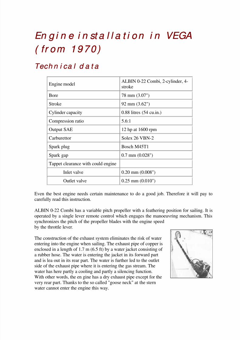
Engine modelALBIN 0-22 Combi, 2-cylinder, 4-
stroke
Bore 78 mm (3.07")
Stroke 92 mm (3.62")
Cylinder capacity 0.88 litres (54 cu.in.)
Compression ratio 5.6:1
Output SAE 12 hp at 1600 rpm
Carburettor Solex 26 VBN-2
Spark plug Bosch M45T1
Spark gap 0.7 mm (0.028")
Tappet clearance with could engine
Inlet valve 0.20 mm (0.008")
Outlet valve 0.25 mm (0.010")
Even the best engine needs certain maintenance to do a good job. Therefore it will pay to
carefully read this instruction.
ALBIN 0-22 Combi has a variable pitch propeller with a feathering position for sailing. It is
operated by a single lever remote control which engages the manoeuvring mechanism. This
synchronizes the pitch of the propeller blades with the engine speed
by the throttle lever.
The construction of the exhaust system eliminates the risk of waterentering into the engine when sailing. The exhaust pipe of copper is
enclosed in a length of 1.7 m (6.5 ft) by a water jacket consisting of
a rubber hose. The water is entering the jacket in its forward part
and is lea out in its rear part. The water is further led to the outletside of the exhaust pipe where it is entering the gas stream. The
water has here partly a cooling and partly a silencing function.
With other words, the en gine has a dry exhaust pipe except for the
very rear part. Thanks to the so called "goose neck" at the stern
water cannot enter the engine this way.
8/8/2019 Vega handbook
http://slidepdf.com/reader/full/vega-handbook 22/36
St a r t i n g St a r t i n g
1. Turn on the main switch 2 as shown in this figure
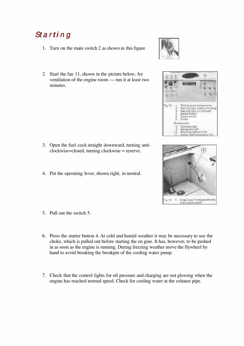
2. Start the fan 11, shown in the picture below, for
ventilation of the engine room — run it at least twominutes.
3. Open the fuel cock straight downward, turning anti-
clockwise=closed, turning clockwise = reserve.
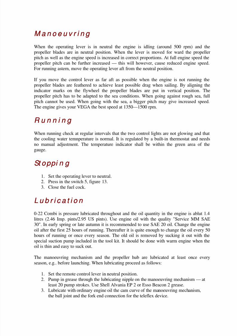
4. Put the operating lever, shown right, in neutral.
5. Pull out the switch 5.
6. Press the starter button 4. At cold and humid weather it may be necessary to use the
choke, which is pulled out before starting the en gine. It has, however, to be pushedin as soon as the engine is running. During freezing weather move the flywheel byhand to avoid breaking the breakpin of the cooling water pump.
7. Check that the control lights for oil pressure and charging are not glowing when the
engine has reached normal speed. Check for cooling water at the exhaust pipe.
8/8/2019 Vega handbook
http://slidepdf.com/reader/full/vega-handbook 23/36
M a n o e u v r i n g M a n o e u v r i n g
When the operating lever is in neutral the engine is idling (around 500 rpm) and the
propeller blades are in neutral position. When the lever is moved for ward the propeller
pitch as well as the engine speed is increased in correct proportions. At full engine speed thepropeller pitch can be further increased — this will however, cause reduced engine speed.
For running astern, move the operating lever aft from the neutral position.
If you move the control lever as far aft as possible when the engine is not running the
propeller blades are feathered to achieve least possible drag when sailing. By aligning the
indicator marks on the flywheel the propeller blades are put in vertical position. The
propeller pitch has to be adapted to the sea conditions. When going against rough sea, full
pitch cannot be used. When going with the sea, a bigger pitch may give increased speed.The engine gives your VEGA the best speed at 1350—1500 rpm.
R u n n i n g R u n n i n g
When running check at regular intervals that the two control lights are not glowing and that
the cooling water temnperature is normal. It is regulated by a built-in thermostat and needs
no manual adjustment. The temperature indicator shall be within the green area of the
gauge.
St oppi n g St oppi n g
1. Set the operating lever to neutral.2. Press in the switch 5, figure 13.
3. Close the fuel cock.
L u b r i c a t i o n L u b r i c a t i o n
0-22 Combi is pressure lubricated throughout and the oil quantity in the engine is ablut 1.4
litres (2.46 Imp. pints/2.95 US pints). Use engine oil with the quality "Service MM SAE
30". In early spring or late autumn it is recommended to use SAE 20 oil. Change the engine
oil after the first 25 hours of running. Thereafter it is quite enough to change the oil every 50
hours of running or once every season. The old oil is removed by sucking it out with thespecial suction pump included in the tool kit. It should be done with warm engine when theoil is thin and easy to suck out.
The manoeuvring mechanism and the propeller hub are lubricated at least once every
season, e.g.. before launching. When lubricating proceed as follows:
1. Set the remote control lever in neutral position.
2. Pump in grease through the lubricating nipple on the manoeuvring mechanism — at
least 20 pump strokes. Use Shell Alvania EP 2 or Esso Beacon 2 grease.
3. Lubricate with ordinary engine oil the cam curve of the manoeuvring mechanism,
the ball joint and the fork end connection for the teleflex device.
8/8/2019 Vega handbook
http://slidepdf.com/reader/full/vega-handbook 24/36
4. Unscrew the plug in the propeller hub. Fit the lubricating nipple which is in the tool
bag and press in grease. Use the same grease as for the manoeuvring mechanism.
The stuffing box 1, figure 12, should be checked every 100 hours of running or at least once
every season. Fill up with grease if necessary. Use "Outboard Grease".
I g n i t i o n syst em I g n i t i o n syst em
The engine has coil ignition, i.e. it is provided with an ignition coil that passes the high-
tension surge to the spark plugs and a distributor that distributes the surge and gives thecorrect preignition at all engine speeds. The engine cannot be started by hand without
battery but even an almost flat battery gives as a rule ignition voltage.
The spark plugs should be checked in conjunction with the launching. The spark gap
should be 0.7 mm (0.028"). Adjustment of the gap is done by bending the side electrode.
The battery is of 12 Volt and has a capacity of 57 Ah. Every second week the electrolyte
level should be checked. The correct level is about 10 mm (just under 1/2") over the battery
plates. Use only distilled water for topping-up.
Su i t a b l e m ea su r es t o be t a ken befor e w i n ter Su i t a b l e m ea su r es t o be t a ken befo r e w i n ter
l a y l a y - - u p u p
During the winter engines run the risk of being damaged by corrosion and therefore it is
recommended to give a thorough anticorrosion treatment before the winter layup. Thesimplest way of anti-corrosion treatment is the following.
1. Empty the fuel tank.
2. Pour in 2 litres (3.50 Imp. pints/4.2 US pints) anti-corrosive fuel consisting of
gasoline and 5% anti-corrosive oil, Albin Motor's part No. 49788.
3. Run the engine for about one hour on varying loads.
4. Change engine oil.5. Drain the cooling water system — taps on port side of engine, below the cooling
water pump and at the fore end of the exhaust jacket.
The remaining anti-corrosive fuel can be kept in the tank during the winter lay-up and needsnot to be drained when launching in the spring.
Mea su r es t o be t a k en w h en l a u n ch i n g Mea su r es t o be t a k en w h en l a u n ch i n g
1. Lubricate the propeller, stuffing box and manoeuvring mechanism.
2. Connect the battery, check the electrolyte level.
3. Check the oil level.
8/8/2019 Vega handbook
http://slidepdf.com/reader/full/vega-handbook 25/36
I n t er i o r a n d equ i pm en t I n t er i o r a n d equ i pm en t
Many suggestions have been made for alterations to the interior. The interior and equipment
now provided is better than that on the early VEGAs. The best possible function has been
considered. After that, the accommodation is a compromise between strict economy and
desirable extras. Further improvements will be made provided they do not result in an
increase in the price. The number of berths can be increased (for children) by placing an
extra mattress between the bunks in the fore peak or by providing upper bunks above thosein the main cabin. These items can be bought as extras. A special locker for crockery and a
book shelf can also be supplied. The saloon berths can be fitted with canvas lee boards to
prevent you falling out in a seaway or when the boat is heeling. These are illustrated in the
price list for VEGA extra equipment.
Va r n i sh , g l u e a n d fa st en i n g Va r n i sh , g l u e a n d fa st en i n g
The interior joinery is mainly of resin glued marine plywood with surface veneers of sapele
on gaboon cores. The finish should normally last for several years but its life may be
prolonged by polishing with furniture polish. After a period the surface finish will have to
be renewed. The varnished parts can be treated with either alkyd or polyurethane basedvarnish in accordance with the manufacturer's instructions. Other parts can be painted with
marine paint. Teak (hatches, handrails, etc) should be oiled several times each season. When
necessary, the teak parts should be scraped and sanded. The best and cheapest "teak oil" is a
mixture of two parts raw linseed oil and one part turpentine thinners. It can be put on witheither a brush or a soft cloth. Excess oil should be wiped off with a cloth moistened with
thinners. If you wish to fix hooks or other fittings to the boat they can either be screwed or
glued on. Fittings can be screwed to all wood parts, including the cabin aft bulkhead, which
is faced with plywood. Holes should be drilled for screws. Fittings that do not carry a great
load can be screwed on to plastic surfaces with short stainless steel self tapping screws. It is
very important that the right size holes are drilled first. A dab of epoxy glue on the threadswill provide considerable holding power. Epoxy glue is so strong that it can be used to glue
metal fittings on to the plastic surfaces. This cannot be done, however, on thermo plastic.
Fittings that have to take a load must be attached with through bolts. The sandwich deck will
take the load of such bolts only where the deck is filled with wood or special filler. (SeeFigure 4). If bolts must be used in other places, the Divinycell filling should be removed
round the hole and glassfibre and resin put to form a strengthening "tube" round the bolt. Apiece of wood should be fitted under the nuts to spread the load. Bolt holes will leak if the
bolts are not packed with a rubber gasket or sealing compound. Glassfibre does not expand
when moist, so leaks are not self sealing as is sometimes the case with a wood boat.
8/8/2019 Vega handbook
http://slidepdf.com/reader/full/vega-handbook 26/36
Fr esh w a t er ( cu r r en t m o d el )Fr esh w a t er ( cu r r en t m o d el )
The water tank holds 65 litres (14¼ gals). The deck filler is situated right forward on the
fore deck. The level of the water in the plastic tank can be checked through the vertical
opening in the bulkhead aft of the tank. A thin breather pipe which finishes just under thedeck is fitted parallel to the filling pipe. If the tank is completely filled the water level will
rise up the breather pipe and a small amount of water will find its way into the bilge; it can
be removed easily with the bilge pump. If the tank is completely filled, water may also run
out into the sink and wash basin if the plastic caps have not been placed over the water
outlet pipes. If it is desired to flush through the tank and supply hoses, the plastic cap should
be left off at the sink and the drain plug removed. Water can then run freely through thesystem, into the sink and overboard. A large lid is fitted to the tank to facilitate inspection
and cleaning. When sailing, the fresh water outlet in the wash basin should be covered with
the plastic cap because with a full water tank, large quantities of water may run out into the
boat when heeling on the port tack. The forward foot pump in the galley is for fresh water
and the aft one for sea water.
Sk i n f i t t i n g s a n d h o se cl i ps Sk i n f i t t i n g s a n d h o se cl i ps
All skin fittings below the waterline — inlet and outlet from the toilet, outlet from the sink,
sea water intake for the galley, and cooling water for the engine have sea cocks to prevent
the water from entering the hull if a hose or pipe should be damaged. Skin fittings for theexhaust and cockpit drains have no sea cocks since they can be reached from deck and
bunged up if need be.
All hose attachements should be checked regularly for leaks and the hose clips tightened if necessary. There are drains from the cockpit seats down to the cockpit floor. When the boat
is heeling a considerable amount of water can run through the leeward hose if it is raining
hard or spray is coming aboard. Should the seat drain hose come adrift, water will run
straight into the boat. The hose fittings should, therefore, be checked frequently. -
8/8/2019 Vega handbook
http://slidepdf.com/reader/full/vega-handbook 27/36
Ven t i l a t i o n a n d h ea t i n g Ven t i l a t i o n a n d h ea t i n g
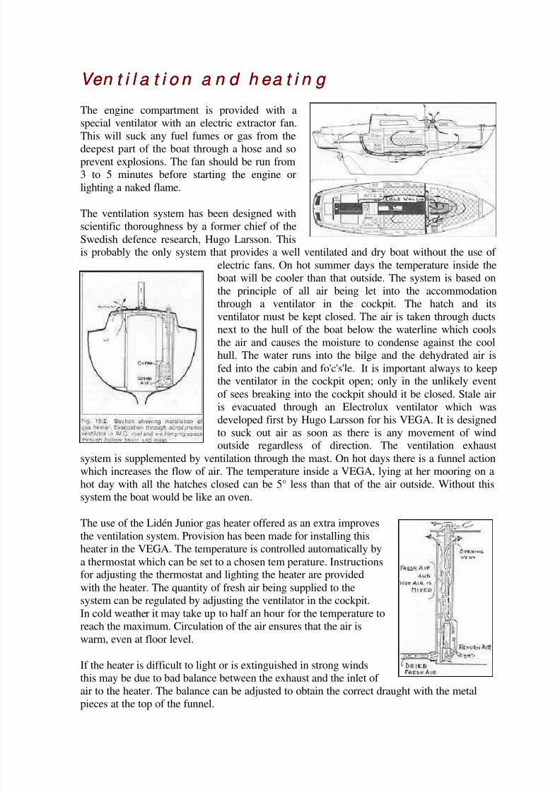
The engine compartment is provided with a
special ventilator with an electric extractor fan.
This will suck any fuel fumes or gas from thedeepest part of the boat through a hose and so
prevent explosions. The fan should be run from
3 to 5 minutes before starting the engine or
lighting a naked flame.
The ventilation system has been designed with
scientific thoroughness by a former chief of the
Swedish defence research, Hugo Larsson. Thisis probably the only system that provides a well ventilated and dry boat without the use of
electric fans. On hot summer days the temperature inside the
boat will be cooler than that outside. The system is based onthe principle of all air being let into the accommodation
through a ventilator in the cockpit. The hatch and its
ventilator must be kept closed. The air is taken through ducts
next to the hull of the boat below the waterline which cools
the air and causes the moisture to condense against the cool
hull. The water runs into the bilge and the dehydrated air is
fed into the cabin and fo'c's'le. It is important always to keepthe ventilator in the cockpit open; only in the unlikely event
of sees breaking into the cockpit should it be closed. Stale air
is evacuated through an Electrolux ventilator which was
developed first by Hugo Larsson for his VEGA. It is designedto suck out air as soon as there is any movement of windoutside regardless of direction. The ventilation exhaust
system is supplemented by ventilation through the mast. On hot days there is a funnel action
which increases the flow of air. The temperature inside a VEGA, lying at her mooring on a
hot day with all the hatches closed can be 5° less than that of the air outside. Without this
system the boat would be like an oven.
The use of the Lidén Junior gas heater offered as an extra improves
the ventilation system. Provision has been made for installing this
heater in the VEGA. The temperature is controlled automatically by
a thermostat which can be set to a chosen tem perature. Instructionsfor adjusting the thermostat and lighting the heater are provided
with the heater. The quantity of fresh air being supplied to the
system can be regulated by adjusting the ventilator in the cockpit.
In cold weather it may take up to half an hour for the temperature to
reach the maximum. Circulation of the air ensures that the air is
warm, even at floor level.
If the heater is difficult to light or is extinguished in strong winds
this may be due to bad balance between the exhaust and the inlet of
air to the heater. The balance can be adjusted to obtain the correct draught with the metalpieces at the top of the funnel.
8/8/2019 Vega handbook
http://slidepdf.com/reader/full/vega-handbook 28/36
Li qu ef i ed Pet r o l eu m Ga s ( LPG) syst em Li qu ef i ed Pet r o l eu m Ga s ( LPG) syst em
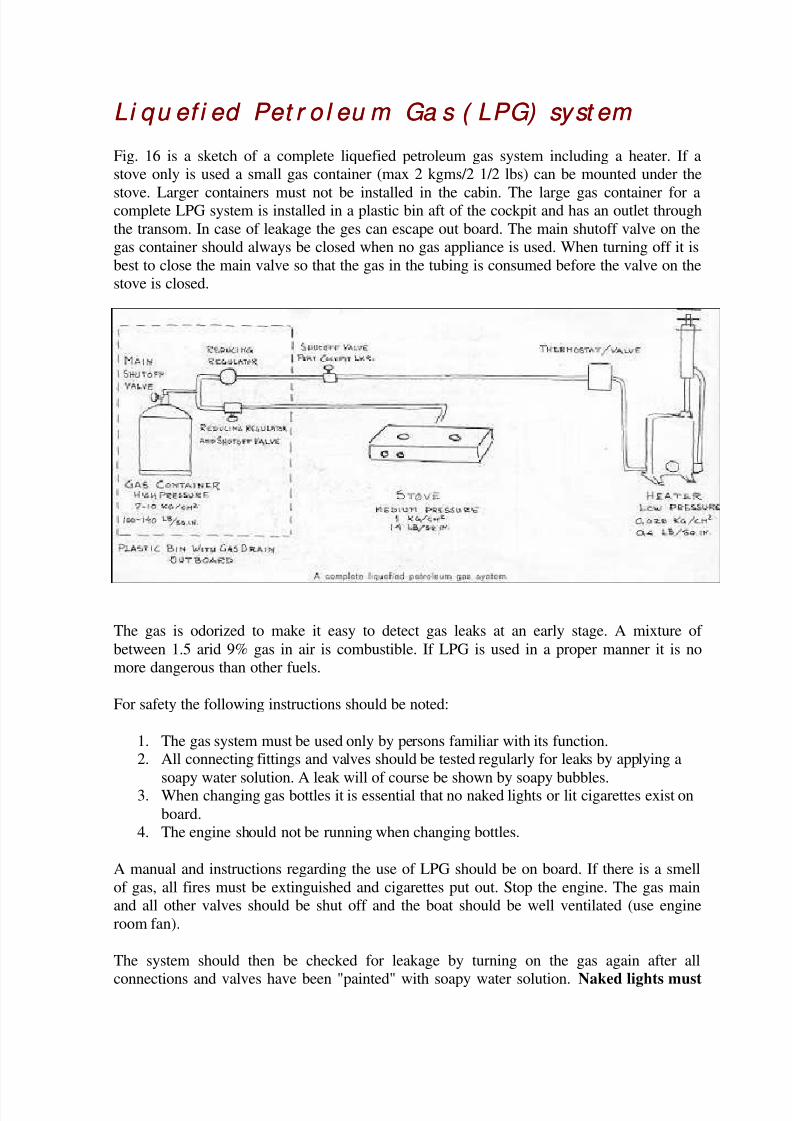
Fig. 16 is a sketch of a complete liquefied petroleum gas system including a heater. If a
stove only is used a small gas container (max 2 kgms/2 1/2 lbs) can be mounted under the
stove. Larger containers must not be installed in the cabin. The large gas container for acomplete LPG system is installed in a plastic bin aft of the cockpit and has an outlet through
the transom. In case of leakage the ges can escape out board. The main shutoff valve on the
gas container should always be closed when no gas appliance is used. When turning off it is
best to close the main valve so that the gas in the tubing is consumed before the valve on the
stove is closed.
The gas is odorized to make it easy to detect gas leaks at an early stage. A mixture of
between 1.5 arid 9% gas in air is combustible. If LPG is used in a proper manner it is no
more dangerous than other fuels.
For safety the following instructions should be noted:
1. The gas system must be used only by persons familiar with its function.2. All connecting fittings and valves should be tested regularly for leaks by applying a
soapy water solution. A leak will of course be shown by soapy bubbles.3. When changing gas bottles it is essential that no naked lights or lit cigarettes exist on
board.
4. The engine should not be running when changing bottles.
A manual and instructions regarding the use of LPG should be on board. If there is a smell
of gas, all fires must be extinguished and cigarettes put out. Stop the engine. The gas main
and all other valves should be shut off and the boat should be well ventilated (use engine
room fan).
The system should then be checked for leakage by turning on the gas again after all
connections and valves have been "painted" with soapy water solution. Naked lights must
8/8/2019 Vega handbook
http://slidepdf.com/reader/full/vega-handbook 29/36
not be used. Check that the main valve is closed again before the leak is repaired. The gas
system must not be used until the fault has been corrected.
In case of a fire on board gas containers must be removed to a safe place. Check that the
valve is closed before removing the container.
During winter lay up gas containers must not be stored on board. The system should be
checked in the spring, noting that valves and connections may have to be repacked and
greased. Copper tubing ought to be changed every second year.
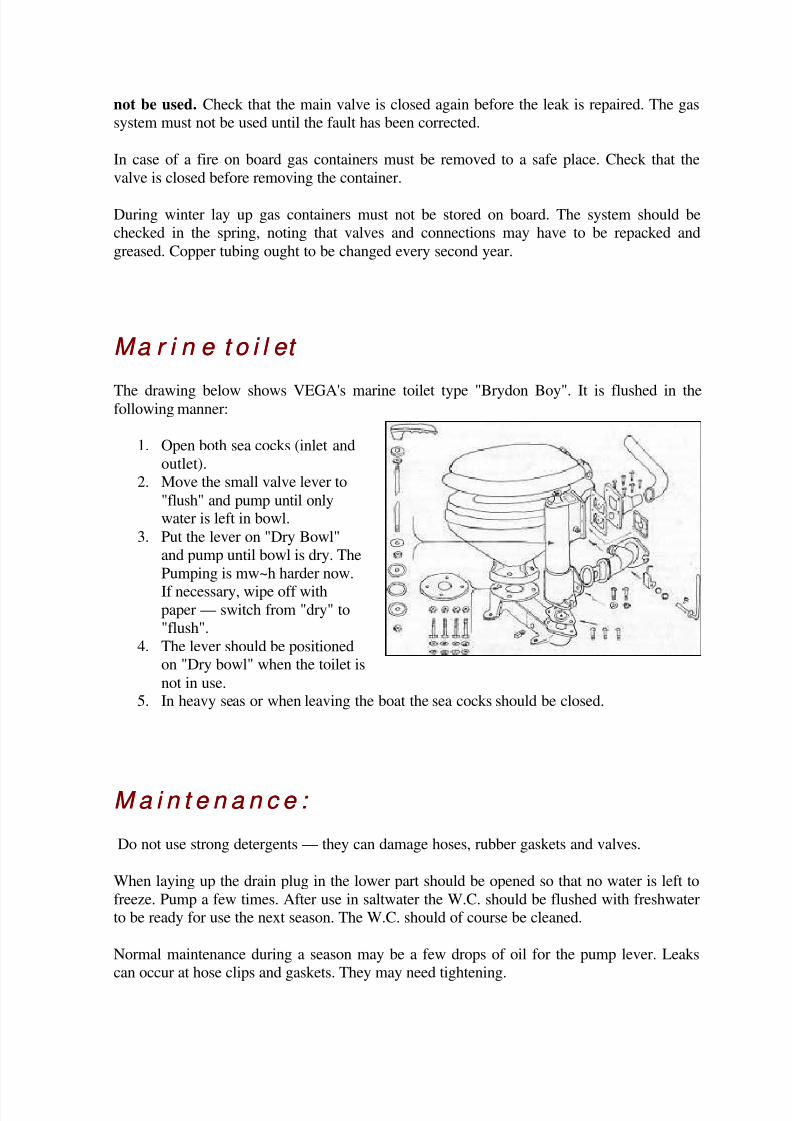
Ma r i n e t o i l et Ma r i n e t o i l et
The drawing below shows VEGA's marine toilet type "Brydon Boy". It is flushed in thefollowing manner:
1. Open both sea cocks (inlet and
outlet).
2. Move the small valve lever to
"flush" and pump until onlywater is left in bowl.
3. Put the lever on "Dry Bowl"
and pump until bowl is dry. The
Pumping is mw~h harder now.
If necessary, wipe off withpaper — switch from "dry" to
"flush".
4. The lever should be positioned
on "Dry bowl" when the toilet is
not in use.5. In heavy seas or when leaving the boat the sea cocks should be closed.
M a i n t e n a n c e : M a i n t e n a n c e :
Do not use strong detergents — they can damage hoses, rubber gaskets and valves.
When laying up the drain plug in the lower part should be opened so that no water is left to
freeze. Pump a few times. After use in saltwater the W.C. should be flushed with freshwater
to be ready for use the next season. The W.C. should of course be cleaned.
Normal maintenance during a season may be a few drops of oil for the pump lever. Leaks
can occur at hose clips and gaskets. They may need tightening.
8/8/2019 Vega handbook
http://slidepdf.com/reader/full/vega-handbook 30/36
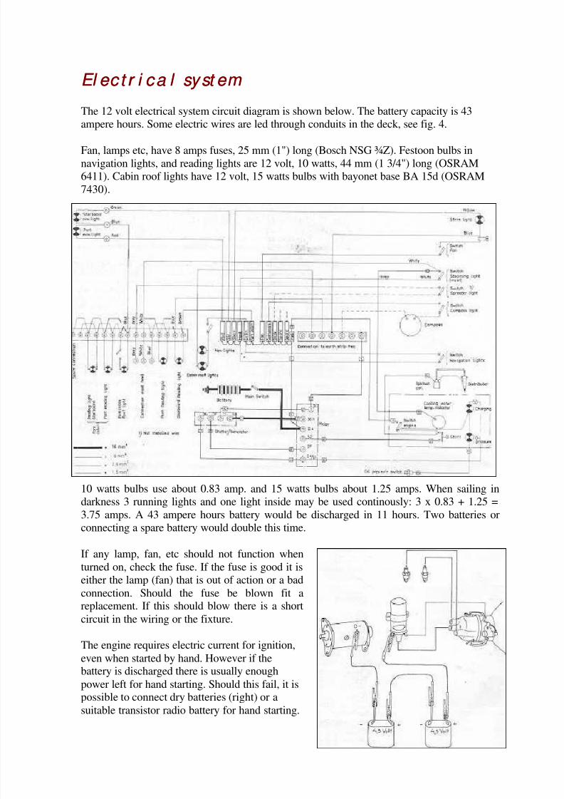
El ec t r i ca l syst em El ec t r i ca l syst em
The 12 volt electrical system circuit diagram is shown below. The battery capacity is 43
ampere hours. Some electric wires are led through conduits in the deck, see fig. 4.
Fan, lamps etc, have 8 amps fuses, 25 mm (1") long (Bosch NSG ¾Z). Festoon bulbs in
navigation lights, and reading lights are 12 volt, 10 watts, 44 mm (1 3/4") long (OSRAM
6411). Cabin roof lights have 12 volt, 15 watts bulbs with bayonet base BA 15d (OSRAM
7430).
10 watts bulbs use about 0.83 amp. and 15 watts bulbs about 1.25 amps. When sailing in
darkness 3 running lights and one light inside may be used continously: 3 x 0.83 + 1.25 =
3.75 amps. A 43 ampere hours battery would be discharged in 11 hours. Two batteries or
connecting a spare battery would double this time.
If any lamp, fan, etc should not function when
turned on, check the fuse. If the fuse is good it is
either the lamp (fan) that is out of action or a bad
connection. Should the fuse be blown fit areplacement. If this should blow there is a short
circuit in the wiring or the fixture.
The engine requires electric current for ignition,
even when started by hand. However if thebattery is discharged there is usually enough
power left for hand starting. Should this fail, it is
possible to connect dry batteries (right) or asuitable transistor radio battery for hand starting.
8/8/2019 Vega handbook
http://slidepdf.com/reader/full/vega-handbook 31/36
E q u i p m e n t E q u i p m e n t
Sa fet y equ i pm en t Sa fet y equ i pm en t
For offshore racing certain equipment is compulsory. Some of the items are included in the
standard equipment of your VEGA, (e.g. pulpits, lifelines, handrails, pump etc).
Rules regarding compulsory equipment are based on long experience and can be judged to
be what is necessary for any long voyage. The safety rules may be different in differentcountries but listed below is what is usually considered necessary.
1. A rubber dinghy or liferaft with C02 bottle: Special liferafts fill the requirements
for lifesaving, but can be used only for that purpose. A rubber dinghy can be used
also as a tender For inshore sailing a simple rubber dinghy without auto matic
inflating can be used If towed or kept on deck inflated such a dinghy is a good
lifesaving devise too.
2. An anchor with warp and at least 2 fathoms of chain: The short chain prevents chafe
near the anchor and also makes the anchor more efficient. In some waters it may be
necessary to use a longer chain or maybe all chain. On rock or kelp a heavy anchor is
necessary — in that case the shape is not so important.
As a storm anchor an ADMIRALITY (Fisherman) type anchor of about 18
kg (40 lbs) is to be preferred. A 12 kgms (25 lbs) light-weight anchor (CQR,
Northill or Danforth) can also be used, but is less efficient than the heavier
one.
A 9 kgms (20 lbs) Danforth anchor should be used normally. This will hold
in most conditions unless the bottom is very bad.
3. Two fire extinguishers: One has to be of certified type (min. 2 kg). Oneextinguisher must be mounted on the bulkhead easily accessible or in an unlocked
seat. A spare extinguisher (maybe a smaller model) ought to be easily accessible in
the fore cabin.
4. A first aid kit.
5. Flares (at least 6 red). Parachute flares or rockets are best. Red hand flares are good
for short distances. Flares and rockets must be changed every 3rd year.6. Two powerful electric hand lamps.
7. Life jackets for each crew member. Certified jackets may be large and cumber
some. Special sailing vests or floating jackets may be better. It may be better to use a
less effective, easily worn flotation than one which is not used because it is lesshandy to wear.
8. Safety harness should be worn by everybody on deck when leaving the cockpit in
heavy weather. This is the most important piece of safety equipment.
9. Lifebuoy with self-igniting light. Buoys are best painted in an orange or yellow
colour to be easily visible. Horseshoe model in a soft material is preferable.
10. Fog signal: Any simple horn can be used.
8/8/2019 Vega handbook
http://slidepdf.com/reader/full/vega-handbook 32/36
Ad d i t i on a l equ i pm en t Ad d i t i on a l equ i pm en t
The compass should be a stable and easily readable type, preferably with built in lighting,
which can be connected to the electric system. Placing the compass under the window in the
bridge deck has great advantages — easy installation, protection, easily visible — but alsodisadvantages — too close to the engine and the electric circuit. Taking a good check on the
deviation (with and without the engine running), you can get a good compass even if the
deviation can be as great as 10° on some courses. A vertical compass on either side of the
cabin door high up on the bulkheads is better but more expensive and uses space on the
bulkheads.
A wind indicator at the masthead can be either a burgee, simple vane indicator or a devise
that registers the wind direction on an electric instrument below. Personally I prefer the'Windex". It is a very sensitive mechanical vane indicator giving very good help both when
beating and running under spinnaker.
A radio receiver is necessary for weather information. A good transistor receiver with
medium and long wave bands can also be used for radio direction finding.
There are also numerous other devises that can be of help: Speedometer, log, echo sounder,special navigation equipment, galley utensils, etc, but they are outside the scope of this
handbook.
8/8/2019 Vega handbook
http://slidepdf.com/reader/full/vega-handbook 33/36
Gl a ssf i b r e a n d m a i n t en a n ce Gl a ssf i b r e a n d m a i n t en a n ce
Th e a d va n t a g es o f g l a ssf i b r e co n st r u ct i o n Th e a d va n t a g es o f g l a ssf i b r e co n st r u ct i o n
Glassfibre reinforced plastic has very quickly become the leading material for hulls and
decks for pleasure crafts. This depends mainly on the following:
1. The material is more economical for series production than any other material used
today.
2. It has great strength in relation to weight; stronger than wood and steel.
3. It has good ageing properties — much better than wood or steel.
4. The maintenance costs are low — small yearly upkeep.
5. It is easy to repair — see below.
Ca r e o f t h e pl a st i c su r f a ces Ca r e o f t h e pl a st i c su r f a c es Glassfibre plastic surfaces are easy to maintain. Lack of maintenance will not cause the
material to deteriorate but without care the surfaces will look bad and the value of the boat
will decrease. Regular cleaning, waxing and polishing are needed.
C l e a n i n g C l e a n i n g
Wash with water and ordinary synthetic detergents. The deck pattern can be scrubbed dry
with a clean brush and some cleaning powder. Heavily soiled parts can be cleaned with one
of the degreasing detergents recommended for cars or special boat cleaners. It is alsopossible to use soap. With care also acetone and carbon tetrachloride can be used. Avoid
using scouring powders, strong alkalis (caustic soda), ammonia or any unknown detergents.
Stains, small scratches and dull parts can be polished or burnished to regain the gloss.
Wa x i n g a n d po l i sh i n g Wa x i n g a n d po l i sh i n g
A well polished surface protects the gelcoat and is less easily soiled and makes the boat look
better. Polishing puts off the time when it becomes necessary to paint the plastic because of
looks. For polishing, use a boat, car or floor wax containing Carnauba Wax. It should be
used in the same manner as when polishing a car. Do not use silikon polish, since this is
very difficult to remove before repairing or paint ing. A boat should be waxed and polished
at least once a year.
8/8/2019 Vega handbook
http://slidepdf.com/reader/full/vega-handbook 34/36
Repa i r i n g sm a l l d a m a g es Repa i r i n g sm a l l d a m a g es
The VEGA small repair kit is used for repairing minor damages in the gelcoat and the outer
part of the lamination. For more complicated repairs, contact a specialist.
Pr epa r i n g fo r a r epa i r Pr epa r i n g f or a r epa i r
Remove dirt in the damage area. Roughen up the surface in the damaged area with an
abrasive paper. Remove the dust thoroughly and check carefully that the damage is free
from moisture.
Mi x i n g a n d a ppl i ca t i o n o f t h e g el co a t M i x i n g a n d a ppl i ca t i o n o f t h e g el co a t
Use a piece of board or a piece of wood and mix the gelcoat with the hardener thoroughly.
The enclosed putty stick can be used for mixing and application. 1/25 of hardener should beused. (This can be approximated).
The ready mixed gelcoat hardens in 15—20 minutes at 18°C (65°F). The surface of the
repair should be slightly higher than the surrounding parts to allow for shrinkage and
burnishing.
Fi n i sh i n g o f Fi n i sh i n g o f a r epa i r a r epa i r
Sand down the top of the hardened gelcoat with abrasive paper No. 220. While the gelcoat is
hardening and still rubbery, a sharp knife can be used to cut away excess material. Continue
with wet and dry paper No. 400 and 600 in mentioned order.
Be careful not to damage the surrounding gelcoat. Where possible, use a sanding block.
Finally the repair should be burnished and waxed (see above).
Gen er a l i n st r u ct i o n s Gen er a l i n st r u ct i o n s
In the air temperature is below 15°C (60°F), use a heater to dry out and then heat the
damage in order to speed up the hardening. Do not put the heater too close.
Hands and tools can be cleaned in acetone [Webmaster's note: you should not expose bareskin to acetone.] A slight difference in colour between the old and the new gelcoat will
disappear after a few months of exposure to weather and sun.
The VEGA repair kit consists of:
200 grams deck gelcoat 2 abrasive papers no 220
200 grams hull gelcoat abrasive papers no 400
40 grams of hardener in a tube 2 abrasive papers no 600
One "putty stick"
8/8/2019 Vega handbook
http://slidepdf.com/reader/full/vega-handbook 35/36
Pa i n t i n g o n pl a st i c su r fa ces Pa i n t i n g o n pl a st i c su r fa ces
With care the plastic surfaces can be kept in good shape for several years without painting.Sooner or later they get so scratched and damaged that it becomes necessary to paint the
boat. Maybe another colour is required. The quality will not be lowered if a boat is painted,provided that the right kind of paint is used in the right manner. Modern two-pot
polyurethane paints are just as strong as a gelcoat and have an equally long life. A painted
boat does not have to be repainted annually.
To get good results it is necessary to prepare the surfaces well. No wax or grease must beleft. The surfaces should be cleaned with white spirit or a polyurethane thinner (silicon wax
cannot be removed). Then the surface should be sanded with a fine wet and dry paper to get
a good grip for the paint. Wash with a lot of water. Follow the instructions from the paintmanufacturer carefully. For the bottom a primer is needed. This may be necessary on all
surfaces. If the original bottom paint (Geveco Racing Special) is to be used, it is not
necessary to sand down or prime. A good washdown is sufficient. If another bottom paint is
to be used, it is necessary to sand the bottom and then use a primer. To paint the bottom,
need app. 1.5 liters (1 1/2 quart). Paint removers or a blow torch must not be used, since
they may damage the glassfibre lamination
Wi n t er st o r a g e a n d Spr i n g co m m i ssi o n i n g Wi n t er st o r a g e a n d Spr i n g co m m i ssi o n i n g
When stored for the winter your VEGA should stand on her cradle or have blocks under thekeel and shores fore and aft, see below. Other methods can be used; study boats stored
locally.
8/8/2019 Vega handbook
http://slidepdf.com/reader/full/vega-handbook 36/36
A winter cover can be anything from a complete boathouse to a simple cover, the same as
used when the boat was delivered. It needs a support to prevent it from sagging down in the
centre of cockpit.
The mast should be supported straight and stored in a dry place. The spreaders should be
taken off, but standing and running rigging may be left.
Before covering up, all loose equipment should be removed and the boat cleaned
thoroughly. To avoid damages from freezing you must pay attention to a few things:
1. Winterize the engine (see engine chapter).
2. Remove batteries and gas containers.
3. Open the bottom plug to drain bilge water.
4. Pump out and drain the toilet.5. Empty the watertank (pump or loosen hose at foot pump).
6. Clean bilges and be sure not to leave any water.
Note: Check gear and decide if anything has to be repaired or replaced.
In spring all yards, boat firms and sailmakers have a lot to do. The earlier you can orderwork or replacements the more certain you can be of getting things done the way you want.
Spring commissioning includes:
1. Cleaning deck and hull.
2. Painting bottom.
3. Oiling teak parts.4. Waxing and polishing plastic surfaces.
5. Rigging, engine, gas system and gear should be checked and adjusted. Bottom
painting and filling grease in the propeller must be made before launching. All other
work can be made with the boat in the water.