Embed Size (px)
Citation preview
Veer Surendra Sai University of Technology, Burla Department of Electrical Engineering
Master of Technology in Power Electronics Control & Drives (Two Years Regular Course) 2016
1
VEER SURENDRA SAI UNIVERSITY OF TECHNOLOGY
BURLA, SAMBALPUR, ODISHA-768018
DEPARTMENT OF ELECTRICAL ENGINEERING
MISSON OF THE DEPARTMENT
To produce Electrical Engineers with dynamic well rounded personalities adaptable to ever
increasing demands of emerging technologies involving analytical and practical skills.
VISION OF THE DEPARTMENT
To develop the department as a renowned academic center of learning in the
discipline of Electrical Engineering.
To establish research and development center of repute so as to encourage active
participation with industry by staff and students to take on practical problemsof
industry and to provide feasible solutions.
To establish tie-ups with institutions of national and international repute and to foster
building up of a wide knowledge base to keep in tune with ever increasing demands
of technologies.
Developing simple, appropriate technologies, which will be instrumental in the up-
liftment of rural society.
Veer Surendra Sai University of Technology, Burla Department of Electrical Engineering
Master of Technology in Power Electronics Control & Drives (Two Years Regular Course) 2016
2
VEER SURENDRA SAI UNIVERSITY OF TECHNOLOGY
BURLA, SAMBALPUR, ODISHA-768018
DEPARTMENT OF ELECTRICAL ENGINEERING
MASTER OF TECHNOLOGY IN POWER ELECTRONICS CONTROL
& DRIVES
PROGRAMME EDUCATIONAL OBJECTIVES
1. Excel professionally in Power Electronics and allied domains.
2. Be empowered to undertake research and development that addresses technological
requirements of Industry and Institutes of higher learning.
3. Adapt to the changing needs of Industry/Society through lifelong learning.
Veer Surendra Sai University of Technology, Burla Department of Electrical Engineering
Master of Technology in Power Electronics Control & Drives (Two Years Regular Course) 2016
3
VEER SURENDRA SAI UNIVERSITY OF TECHNOLOGY
BURLA, SAMBALPUR, ODISHA-768018
DEPARTMENT OF ELECTRICAL ENGINEERING
MASTER OF TECHNOLOGY IN POWER ELECTRONICS CONTROL & DRIVES
PROGRAMME OUTCOMES
a) have an ability to evaluate and analyse problems related to Power Electronic Systems
and incorporate the principles in the state of art systems for further improvement
b) be able to investigate critical Power Electronics problems and to arrive at possible
solutions independently, by applying theoretical and practical considerations
c) be able to solve Power Electronics problems such as switching control, converter
design, analysis and control of solid state drives and stability studies
d) be able to develop appropriate power converters for sustainable energy technologies
e) be able to identify optimal solutions for improvising power conversion and transfer
capability, enhancing power quality and reliability through PE based solutions
f) be able to evolve new power electronic topologies and control schemes based on
literature survey and propose solutions through appropriate research methodologies,
techniques and tools, and also by designing and conducting experiments
g) be able to work on small, well-defined projects with particular goals to provide real
time solutions pertaining to power electronics
h) be able to develop, choose, learn and apply appropriate techniques, various resources
including sophisticated digital controllers and IT tools for modern power electronic
system simulation, including prediction and modelling with existing constraints
i) be able to pursue challenging professional endeavours based on acquired competence
and knowledge
j) be a responsible professional with intellectual integrity, code of conduct and ethics of
research, being aware of the research outcomes and serve towards the sustainable
development of the society
k) be capable of examining critically the outcomes of research and development
independently without any external drive
Veer Surendra Sai University of Technology, Burla Department of Electrical Engineering
Master of Technology in Power Electronics Control & Drives (Two Years Regular Course) 2016
4
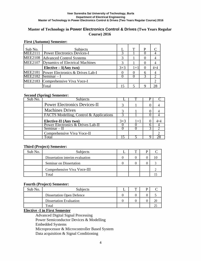
Master of Technology in Power Electronics Control & Drives (Two Years Regular
Course) 2016
First (Autumn) Semester:
Sub No. Subjects L T P C MEE2111 Power Electronics Devices-I 3 1 0 4
MEE2108 Advanced Control Systems 3 1 0 4
MEE2107 Dynamics of Electrical Machines 3 1 0 4
Elective – I(Any two) 3+3 1+1 0 4+4
MEE2181 Power Electronics & Drives Lab-I 0 0 6 4 MEE2182 Seminar – I 0 0 3 2
MEE2183 Comprehensive Viva Voce-I 2
Total 15 5 9 28
Second (Spring) Semester: Sub No. Subjects L T P C
Power Electronics Devices-II 3 1 0 4
Machines Drives 3 1 0 4 FACTS Modelling, Control & Applications 3 1 0 4
Elective-II (Any two) 3+3 1+1 0 4+4 Power Electronics & Drives Lab-II 0 0 6 4 Seminar – II 0 0 3 2
Comprehensive Viva Voce-II 2 Total 15 5 9 28
Third (Project) Semester:
Sub No. Subjects L T P C
Dissertation interim evaluation 0 0 0 10 Seminar on Dissertation 0 0 0 3
Comprehensive Viva Voce-III 2 Total 15
Fourth (Project) Semester:
Sub No. Subjects L T P C
Dissertation Open Defence 0 0 0 5 Dissertation Evaluation 0 0 0 20 Total 25
Elective -I in First Semester Advanced Digital Signal Processing
Power Semiconductor Devices & Modelling
Embedded Systems
Microprocessor & Microcontroller Based System
Data acquisition & Signal Conditioning
Veer Surendra Sai University of Technology, Burla Department of Electrical Engineering
Master of Technology in Power Electronics Control & Drives (Two Years Regular Course) 2016
5
Elective -II in Second Semester Digital Simulation of Power Electronic Systems
Advanced Control of Drives
Switch Mode & Resonant Converters
Power Quality
Non Linear System Theory
(1ST
SEMESTER) POWER ELECTRONICS DEVICES-I (3-1-0)
Course Objectives:
1. Students will be able to understand the concept of power electronic converters.
2. Students will be able to relate to the applications of phase controlled rectifiers.
3. Students will be able to comprehend the importance of AC voltage controllers and
cyclo- converters for various industrial applications.
4. Students will be able to analyze and design switch mode power electronic converters for
various applications including microprocessor power supplies, renewable energy
systems, and motor drives.
5. Able to analyze pulse width modulated inverters used for variable speed drives.
MODULE-I (10 HOURS) Line Frequency Diode Rectifiers. Single-Phase Diode Bridge Rectifiers with Capacitor Filter .
Voltage Doubler Rectifiers. Effect of Single Phase Rectifiers on Neutral Currents in a Three
Phase Four-Wire System. Three Phase half wave rectifier with resistive load . Three phase full
wave rectifier. Double Y type rectifier. Single Phase rectifiers with LC filter . Cascaded LC
Filter . LC Filter Design. Three Phase Rectifier Circuits. Design of Power Transformers for
Rectifiers . Inrush Currents and Overvoltages at turn on in Rectifier Circuits Input Line Current
Harmonics and power factor. MODULE-II (10HOURS) Line Frequency Phase-Controlled Rectifiers and Inverters. Single Phase - Half Wave Controlled
Rectifier with R, RL, RL with Flywheel diode loads. Full Wave Controlled Rectifier with
various kinds of loads. Half Controlled and Full Controlled Bridges with passive and active
loads - Input Line Current Harmonics and Power Factor- Inverter Mode of Operation - Three
Veer Surendra Sai University of Technology, Burla Department of Electrical Engineering
Master of Technology in Power Electronics Control & Drives (Two Years Regular Course) 2016
6
Phase. Half Wave Controlled rectifier with RL Load. Half Controlled Bridge with RL Load.
Fully Controlled Bridge with RL Load. Input Side Current Harmonics and Power Factor - Dual
Converters. Circulating Current Mode and Non-Circulating Current Mode. MODULE-III (8 HOURS) AC Voltage Regulators and DC choppers-Types of ac voltage regulators -Single phase full
wave ac voltage controller - Single phase transformer tap changer - Multistep transformer tap
changer. D.C chopper circuits, Type-A, B, C, D and E configurations, Analysis of Type-A
chopper with R-L load. -Voltage and current commutated Choppers
MODULE-IV (12 HOURS) Switch-Mode dc-ac Inverters. Basic Concepts . Single Phase Inverters . Push Pull , Half Bridge
and Full Bridge Square Inverters .Blanking Time .Single Pulse Modulation of Single Phase
Square Wave Inverters . Multi pulse modulation .- PWM Principles . Sinusoidal Pulse Width
Modulation in Single Phase Inverters . Choice of carrier frequency in SPWM .spectral Content
of output . Bipolar and Unipolar Switching in SPWM - Maximum Attainable DC Voltage
Switch Utilization .Reverse Recovery Problem and Carrier Frequency Selection . Output Side
Filter Requirements and Filter Design - Ripple in the Inverter Output - DC Side Current. -
Three Phase Inverters -Three Phase Square Wave /Stepped Wave Inverters . Three Phase
SPWM Inverters . Choice of Carrier Frequency in Three Phase SPWM Inverters . Output Filters
. DC Side Current . Effect of Blanking Time on Inverter Output Voltage. BOOKS
1. Ned Mohan et.al:“Power Electronics”, John Wiley and Sons.P.C. Sen : “Power
Electronics”, Tata McGraw Hill
2. G.K.Dubey et.al ,“Thyristorised Power Controllers”, Wiley Eastern Ltd.
3. B. K Bose : “Modern Power Electronics and AC Drives”, Pearson Education (Asia)
Course Outcomes:
1. Comprehend the basic principles of switch mode power converters.
2. Understand the operating principles and models of different types of power electronic
converters AC-AC, AC-DC, DC-AC and DC-DC converter systems.
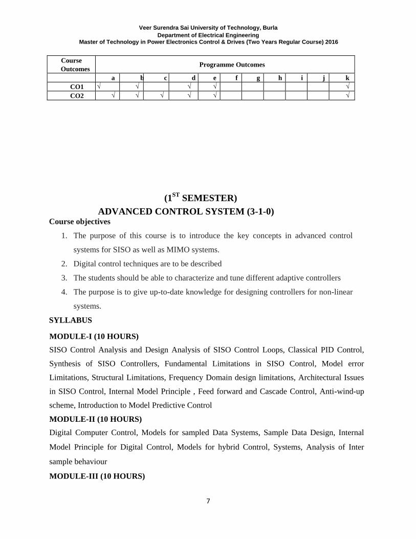
Mapping of Course Outcomes to Programme Outcomes
Veer Surendra Sai University of Technology, Burla Department of Electrical Engineering
Master of Technology in Power Electronics Control & Drives (Two Years Regular Course) 2016
7
Course
Outcomes Programme Outcomes
a b c d e f g h i j k
CO1 √ √ √ √ √
CO2 √ √ √ √ √ √
(1ST
SEMESTER) ADVANCED CONTROL SYSTEM (3-1-0)
Course objectives
1. The purpose of this course is to introduce the key concepts in advanced control
systems for SISO as well as MIMO systems.
2. Digital control techniques are to be described
3. The students should be able to characterize and tune different adaptive controllers
4. The purpose is to give up-to-date knowledge for designing controllers for non-linear
systems.
SYLLABUS
MODULE-I (10 HOURS) SISO Control Analysis and Design Analysis of SISO Control Loops, Classical PID Control,
Synthesis of SISO Controllers, Fundamental Limitations in SISO Control, Model error
Limitations, Structural Limitations, Frequency Domain design limitations, Architectural Issues
in SISO Control, Internal Model Principle , Feed forward and Cascade Control, Anti-wind-up
scheme, Introduction to Model Predictive Control MODULE-II (10 HOURS) Digital Computer Control, Models for sampled Data Systems, Sample Data Design, Internal
Model Principle for Digital Control, Models for hybrid Control, Systems, Analysis of Inter
sample behaviour
MODULE-III (10 HOURS)
Veer Surendra Sai University of Technology, Burla Department of Electrical Engineering
Master of Technology in Power Electronics Control & Drives (Two Years Regular Course) 2016
8
Advanced SISO Control, SISO CONTROLLER Parametrisations, Control Design Based on
Optimisation, Synthesis via state space methods, Introduction to Nonlinear Control MODULE-IV (10 HOURS) MIMO Control Essentials, Analysis of MIMO Control Loops, Exploiting SISO Techniques in
MIMO Control, MIMO Control Design: Design via Optimal control techniques, Model
Predictive Control MIMO Controller Parametrisations, Decoupling
TEXT BOOKS:
[1]. Graham C. Goodwin, Stefan F.Graebe, Mario E.Salgado, “Control System Design”, PHI-2002.
[2]. M. Athans and P. Falb, “Optimal control”, MGH
[3]. K. Astrom, and B.wittenmark, “Computer Control Systems: Theory and design”, Prentice Hall
Course Outcomes:
1. At the end of the course students will be able to apply the modeling concepts.
2. The students will learn issues of sensitivity, stability, and loop synthesis as well
as feedforward and cascade structures
3. The students will learn designs for digital control and how the constraint of the trade-off
web be circumvented by optimization.
4. The students will learn techniques specifically aimed at MIMO Control Problems
5. Students can apply Matlab Real Time programming/ LabVIEW to the model
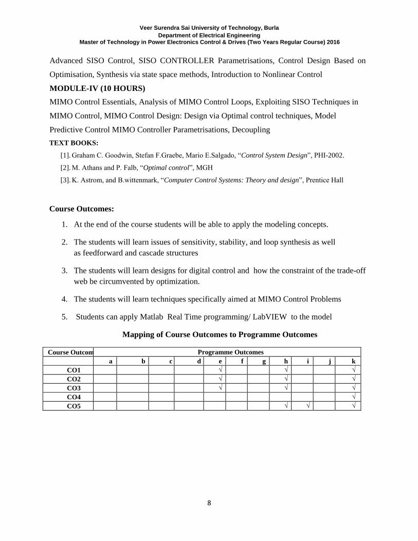
Mapping of Course Outcomes to Programme Outcomes
Course Outcomes Programme Outcomes
a b c d e f g h i j k
CO1 √ √ √
CO2 √ √ √
CO3 √ √ √
CO4 √
CO5 √ √ √
Veer Surendra Sai University of Technology, Burla Department of Electrical Engineering
Master of Technology in Power Electronics Control & Drives (Two Years Regular Course) 2016
9
(1ST
SEMESTER) DYNAMICS OF ELECTRICAL MACHINES (3-1-0)
Course Objectives:
1. To provide knowledge about the fundamentals of electrical machines by using
transformation theory based mathematical modelling.
2. To impart knowledge about principle of operation and performance of DC,
Synchronous, Induction machines and transformers.
3. To analyze the steady state and dynamic state operation of DC, Synchronous, Induction
machines and transformers.
SYLLABUS MODULE-I (10 HOURS) Singly excited circuits, Coupled circuits, Solution of Electro-dynamical Equations by Euler’s
method and Runge-Kutta method. Linearization of the Dynamic Equations and Small Signal
Stability.
Elementary DC Machine, Voltage and torque equations, Basic types of DC machines, Dynamic
characteristics of DC motors, time-domain block diagrams and state equations, solution of
dynamic characteristics by Laplace transformation. MODULE-II (10 HOURS) The basis of General Theory and Generalized Equation of A.C machines, Equation in terms of
phases variable park’s transformation, Various reference frames, Derivation of two-axis
equation, Torque equation, Field and damper windings, Equivalent circuits, Operational
Veer Surendra Sai University of Technology, Burla Department of Electrical Engineering
Master of Technology in Power Electronics Control & Drives (Two Years Regular Course) 2016
10
impedances and frequency response loci, Modified equation with more accurate coupling
between field and damper windings.
MODULE-III (10 HOURS) Synchronous Generator short circuit and system faults: Symmetrical short circuit of unloaded
generator, Analysis of short circuit oscillograms, short circuit of loaded synchronous generator,
Unsymmetrical short of synchronous generator, system fault calculation, Sudden load changes,
Equivalent circuit under transient condition, Constant flux linkage theorem, Simplified phasor
diagram for transient changes.
MODULE-IV (10 HOURS) Induction machines: General equation of the induction motor (equation), Application of
equation in primary and secondary reference frames and complex form of equation, Short
circuit and fault current due to the induction motor, fault calculation.
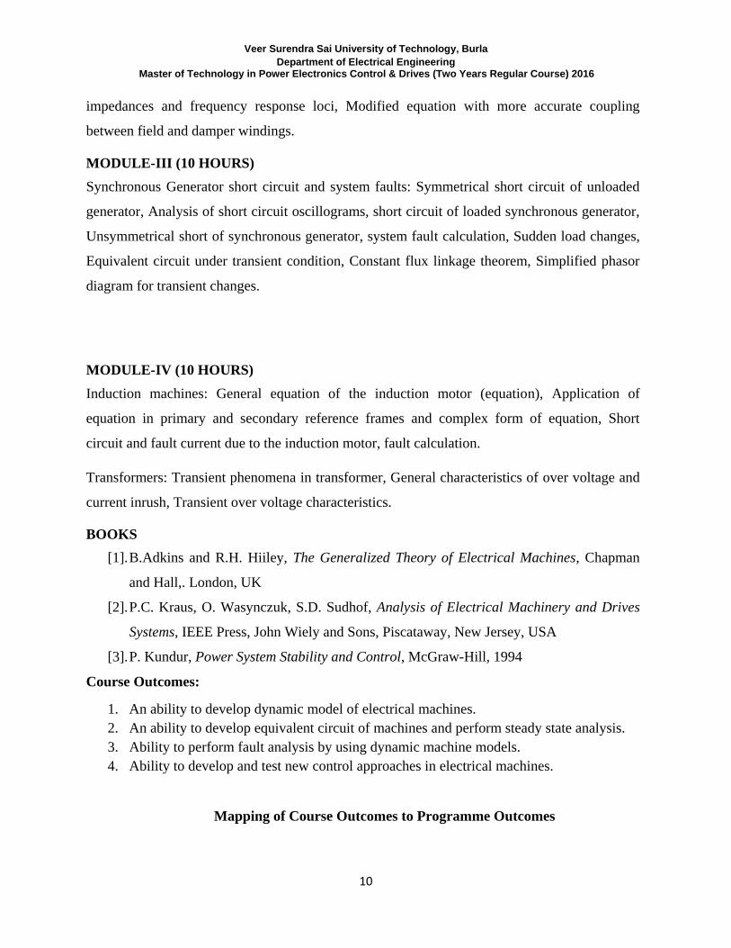
Transformers: Transient phenomena in transformer, General characteristics of over voltage and
current inrush, Transient over voltage characteristics.
BOOKS
[1]. B.Adkins and R.H. Hiiley, The Generalized Theory of Electrical Machines, Chapman
and Hall,. London, UK
[2]. P.C. Kraus, O. Wasynczuk, S.D. Sudhof, Analysis of Electrical Machinery and Drives
Systems, IEEE Press, John Wiely and Sons, Piscataway, New Jersey, USA
[3]. P. Kundur, Power System Stability and Control, McGraw-Hill, 1994
Course Outcomes:
1. An ability to develop dynamic model of electrical machines.
2. An ability to develop equivalent circuit of machines and perform steady state analysis.
3. Ability to perform fault analysis by using dynamic machine models.
4. Ability to develop and test new control approaches in electrical machines.
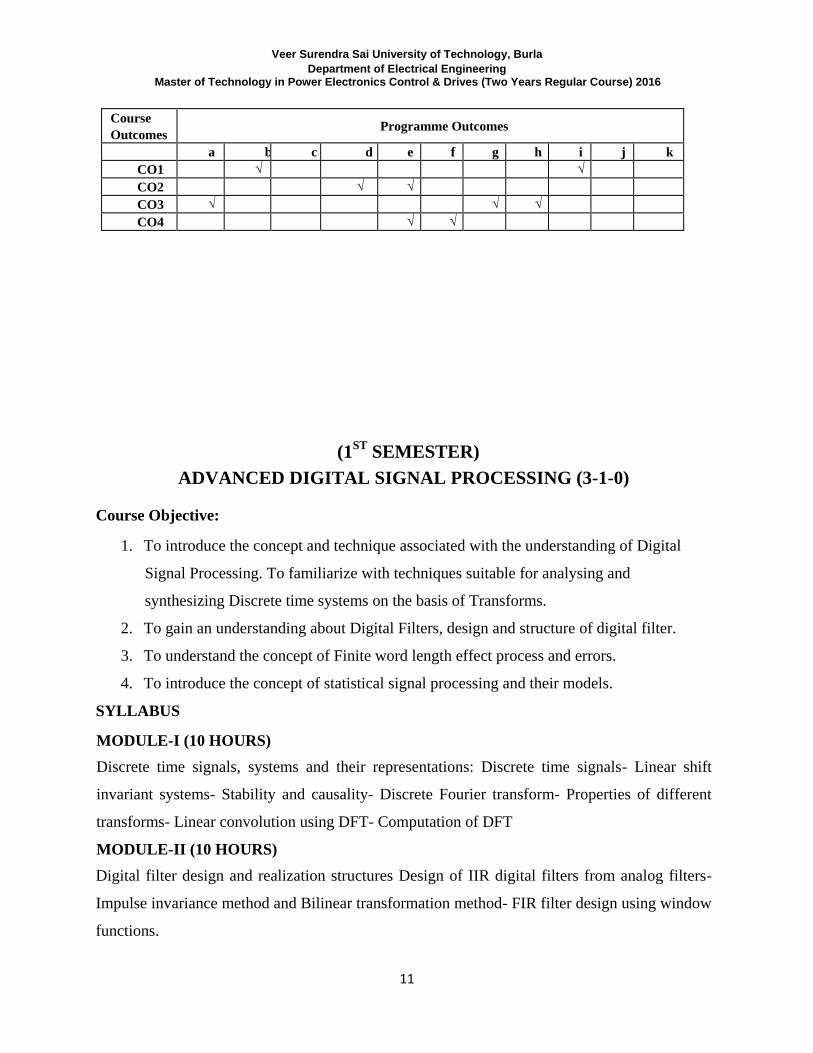
Mapping of Course Outcomes to Programme Outcomes
Veer Surendra Sai University of Technology, Burla Department of Electrical Engineering
Master of Technology in Power Electronics Control & Drives (Two Years Regular Course) 2016
11
Course
Outcomes Programme Outcomes
a b c d e f g h i j k
CO1 √ √
CO2 √ √
CO3 √ √ √
CO4 √ √
(1ST
SEMESTER) ADVANCED DIGITAL SIGNAL PROCESSING (3-1-0)
Course Objective:
1. To introduce the concept and technique associated with the understanding of Digital
Signal Processing. To familiarize with techniques suitable for analysing and
synthesizing Discrete time systems on the basis of Transforms.
2. To gain an understanding about Digital Filters, design and structure of digital filter.
3. To understand the concept of Finite word length effect process and errors.
4. To introduce the concept of statistical signal processing and their models.
SYLLABUS MODULE-I (10 HOURS) Discrete time signals, systems and their representations: Discrete time signals- Linear shift
invariant systems- Stability and causality- Discrete Fourier transform- Properties of different
transforms- Linear convolution using DFT- Computation of DFT
MODULE-II (10 HOURS) Digital filter design and realization structures Design of IIR digital filters from analog filters-
Impulse invariance method and Bilinear transformation method- FIR filter design using window
functions.
Veer Surendra Sai University of Technology, Burla Department of Electrical Engineering
Master of Technology in Power Electronics Control & Drives (Two Years Regular Course) 2016
12
Comparison of IIR and FIR digital filters- Basic IIR and FIR filter realization structures-Signal
flow graph representations.
MODULE-III (10 HOURS) Analysis of finite word-length effects Quantization process and errors- Coefficient quantization
effects in IIR and FIR filters- A/D conversion noise- Arithmetic round-off errors- Dynamic
range scaling- Overflow oscillations and zero input limit cycles in IIR filters
MODULE-IV (10 HOURS) Statistical signal processing Linear Signal Models All pole, All zero and Pole-zero models.
Power spectrum estimation- Spectral analysis of deterministic signals. Estimation of power
spectrum of stationary random signals-Optimum linear filters-Optimum signal estimation-Mean
square error estimation-Optimum FIR and IIR filters.
BOOKS [1]. John G. Proakis, and Dimitris G. Manolakis, Digital Signal Processing (third edition),
Prentice-Hall of India Pvt. Ltd, New Delhi, 1997
[2]. Alan V . Oppenheim, Ronald W. Schafer, Discrete-Time Signal Processing, Prentice-
Hall of India Pvt. Ltd., New Delhi, 1997
[3]. A. NagoorKani, Digital Signal Processing(Second edition, Mc Graw Hill
[4]. Sanjit K Mitra, Digital Signal Processing: A computer-based approach ,Tata Mc Grow-
Hill edition .1998
Course Outcomes:
When the students have passed the course, they shall be able
1. To understand the fundamental concept of Digital Signal Processing, Discrete Fourier
Transform and its application.
2. Apply several design techniques for IIR type digital filter, apply a design technique for
FIR filter. Also understand the filter realisation structures.
3. To understand the errors of word length effect and their correction techniques.
To understand spectral characteristics in form of power spectral estimation.

Veer Surendra Sai University of Technology, Burla Department of Electrical Engineering
Master of Technology in Power Electronics Control & Drives (Two Years Regular Course) 2016
13
Mapping of Course Outcomes to Programme Outcomes
Course Outcomes Programme Outcomes
a b c d e f g h i j k
CO1 √ √ √ √ √
CO2 √ √
CO3 √ √
Veer Surendra Sai University of Technology, Burla Department of Electrical Engineering
Master of Technology in Power Electronics Control & Drives (Two Years Regular Course) 2016
14
(1ST
SEMESTER)
POWER SEMICONDUCTOR DEVICES & MODELING
(3-1-0) Course Objectives:
1. Students will learn everything about construction and switching charecteristics of
different solid state devices like Power MOSFET, IGBT, GTO etc.
2. Students will design the drive circuit,methods of cooling and protection of solid state
power devices.
3. Students will understand the operation, effect of blanking time, Harmonic Elimination
methods, Bang-bang and space vector modulation techniques of Resonant DC-DC
converters.
4. Students will understand the Regulated PWM Voltage Source Inverters.
5. Students will understand Hysteresis Control of Areas of application of Current
Regulated VSI.
6. Students will know about Shunt Reactive Power Compensators, Switched Capacitors
Static Reactor Compensators based on thyristors for power factor control.
7. Students will have exposure to introductory knowledge ofVector controlled and slip-
power controlled Induction motor drives and Application of PC, DSP and
microprocessor in machine drives.
SYLLABUS MODULE-I (10 HOURS) Solid State Power Devices: Construction and switching characteristics of Gate Turnoff
Thyristor (GTO), .Power BJTs, Power MOSFETs, Insulated Gate Bipolar Transistors (IGBTs),
Design of above devices drive circuits, switching and aid circuits. Methods of cooling and
Protection
MODULE-II (10 HOURS) Resonant DC-DC Converters: Operation, characteristics and design equations, Control
techniques and application. Three Phase Square Wave /Stepped Wave Inverters. Three Phase
SPWM Inverters. Effect of Blanking Time on Inverter Output Voltage. Selective Harmonic
Elimination Method. Current controlled PWM, Bang-bang and space vector modulation
Veer Surendra Sai University of Technology, Burla Department of Electrical Engineering
Master of Technology in Power Electronics Control & Drives (Two Years Regular Course) 2016
15
techniques.
MODULE-III (10 HOURS) Current Regulated Inverter -Current Regulated PWM Voltage Source Inverters. Hysteresis
Control - Areas of application of Current Regulated VSI. Switched Mode Rectifier - Operation
of Single/Three Phase Bridges in Rectifier Mode. Control Principles. Special Inverter
Topologies - Current Source Inverter. Analysis of Single Phase Capacitor Commutated CSI.
Resonant DC-link VSI, Its operation characteristics design and control. MODULE-IV (10 HOURS) Power Factor Control - Shunt Reactive Power Compensators. Switched Capacitors. Static
Reactor Compensators based on thyristors. Static Reactive VAr Generators using PWM Current
Regulated VSIs. Active power line conditioners, Active Power Filtering. Harmonic Generation
by PE Equipment. Harmonic Pollution Standards. PWM Current Regulated VSI based
implementation of a Single Phase Active Power Filter. Vector controlled and slip-power
controlled Induction motor drives. Application of PC, DSP and microprocessor in machine
drives BOOKS [1]. Ned Mohan , Tore M. Undeland , William P.Robbins , “ Power Electronics: Converters,
Applications & Design “, John Willey & Sons , INC [2]. M H Rashid, “Power Electronics, Prentice Hall India,1993 [3]. B. K Bose, Modern Power Electronics and AC Drives”, Pearson Education (Asia), 1992. [4]. Robert W. Erickson , D. Makimovic , “ Fundamentals of Power Electronics ” , 2
nd
edition ,
Kluwer Academics Publishers
Course Outcomes:
When the students have passed the course, they shall be able to
CO1: Use of various solid state devices and Design their drive circuit.
CO2:How to control the firing at Zero current and voltage in Resonant DC-DC converter.
CO3: Use of control stratergy for power factor control of inverters.

Veer Surendra Sai University of Technology, Burla Department of Electrical Engineering
Master of Technology in Power Electronics Control & Drives (Two Years Regular Course) 2016
16
Course Outcomes Programme Outcomes
a b c d e f g h i j k
CO1
√ √
√
CO2 √ √ √ √
√
CO3 √ √ √
Veer Surendra Sai University of Technology, Burla Department of Electrical Engineering
Master of Technology in Power Electronics Control & Drives (Two Years Regular Course) 2016
17
(1ST
SEMESTER) EMBEDDED SYSTEM (3-1-0)
Course Objectives:
1. Architecture of Embedded system
2. High level program design UML of Embedded system .
3. Coding using assembly , C , C++ of Embedded system
4. Use of Real Time operating system ( RTOS ) in Embedded system development.
SYLLABUS MODULE-I (10 HOURS) Introduction: An embedded system, Processor in the system, Other hardware units, Software
embedded into a systems, exemplary system-in-chip, Devices and Device Drivers : I/O
devices, Timer and counting devices, serial communication using the IC, CAN and advance
I/O buses between the networked multiple devices. Host system or computer parallel
communication between the networked I/O multiple devices using the ISA, PCI, PCI-X and
advance buses. Device drivers, Parallel port devices drivers in a system, Serial port device
drives in a system, Interrupt servicing (Handling) mechanism. MODULE-II (10 HOURS) Software and Programming Concept : Processor selection for an embedded system, memory
selection for an embedded system, Embedded programming in C++, Embedded programming
in JAVA, Unified modeling language (UML), Multiple processes and application, problem of
sharing data by multiple tasks and routines, Inter process communication.
MODULE-III (10 HOURS) Real time Operating System: Operating system services, I/O subsystem, Network operating
system, Real Time and embedded system, Need of well tested and debugged Real Time
operating system (RTOS), Introduction to C/OS-II.Case studies of programming with RTOS :
Case study of an embedded system for a smart card
MODULE-IV (10 HOURS) Hardware and Software Co-design : Embedded system project management, Embedded
system design and co-design issues in system development process, design cycle in the
Veer Surendra Sai University of Technology, Burla Department of Electrical Engineering
Master of Technology in Power Electronics Control & Drives (Two Years Regular Course) 2016
18
development phase for an embedded system, Use of software tools for development of an
embedded system, Issues in embedded system design.
BOOKS [4]. Embedded System Architecture, Programming and Design, Raj Kamal, TMH [5]. Hardware Software Codesign of Embedded System, Ralf Niemann, Kulwer Academic [6]. Embedded Real time system Programming, Sriram V. lyer and Pankaj Gupat, TMH
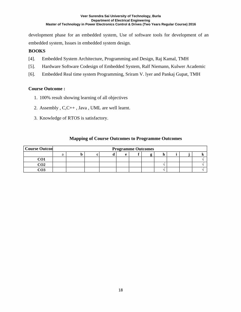
Course Outcome :
1. 100% result showing learning of all objectives
2. Assembly , C,C++ , Java , UML are well learnt.
3. Knowledge of RTOS is satisfactory.
Mapping of Course Outcomes to Programme Outcomes
Course Outcomes Programme Outcomes
a b c d e f g h i j k
CO1 √
CO2 √ √
CO3 √ √
Veer Surendra Sai University of Technology, Burla Department of Electrical Engineering
Master of Technology in Power Electronics Control & Drives (Two Years Regular Course) 2016
19
(1ST
SEMESTER) MICROPROCESSOR AND MICROCONTROLLER BASED
SYSTEMS (3-1-0)
Course Objectives:
The objective of this course is to provide extensive knowledge of
1. Microprocessor and microcontroller based systems and its interfacing techniques and
assembly language programming in 8086, Intel 8051, Intel 8096 and Motorola 68HC11.
2. Architectural model of Intel 8096, Motorola 68HC11, Pentium microprocessors.
3. Data transfer technique in communication media and various Bus standards.
4. Concept of programming logic unit.
SYLLABUS MODULE-I (10 HOURS) (Prerequisite: A basic course on 8 bit ups such as 8085), 16-bit microprocessor(one well
known processor, say 8086 to 68000 to be taken as case study)-quick overview of the
instruction set, Assembly language programming. Interrupt structure, Interfacing memory and
IO devices. Memory organizations. Standard peripherals and their interfacing-(sw and hw
aspects) color graphic terminals and ASCII keyboards, mouse, floppy and hard disc drive,
other storage media (optical disks, Digital Audio Tapes etc.) MODULE-II (10 HOURS) Data transfer techniques-Asynchronous and synchronous. Serial and parallel interface
standards. Communication media and adapters. Modems and their interfacing. Bus structures
and standards-basic concepts. Example of a bus standard (PC-VME bus). Salient features of
other processors (80286386486 or 680206803068040). Microcontrollers and digital signal
processors. IO processors and arithmetic coprocessors. Logic design for microprocessor-based
systems-design of state. MODULE-III (10 HOURS) Introduction to Microcontrollers - Motorola 68HC11 - Intel 8051 - Intel 8096 - Registers -
Veer Surendra Sai University of Technology, Burla Department of Electrical Engineering
Master of Technology in Power Electronics Control & Drives (Two Years Regular Course) 2016
20
Memories - I/O Ports - Serial Communications - Timers - Interrupts.
MODULE-IV (10 HOURS) Instructions in Microcontrollers - Interfaces - Introduction to Development of a
Microcontroller Based System - Concept of a Programmable Logic Controller-Features and
parts in a PLC unit. BOOKS [1]. John.F.Wakerly: Microcomputer Architecture and Programming, John Wiley and Sons. [2]. Ramesh S.Gaonker: Microprocessor Architecture, Programming and Applications with
the 8085, Penram International Publishing (India). [3]. Yu-Cheng Liu and Glenn A.Gibson: Microcomputer systems: The 8086/8088 Family
Architecture, Programming and Design, Prentice Hall of India. [4]. Raj Kamal: The Concepts and Features of Microcontrollers, Wheeler Publishing.
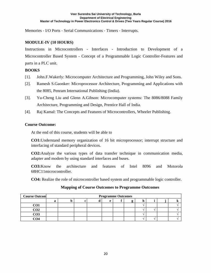
Course Outcome:
At the end of this course, students will be able to
CO1:Understand memory organization of 16 bit microprocessor; interrupt structure and
interfacing of standard peripheral devices.
CO2:Analyze the various types of data transfer technique in communication media,
adapter and modem by using standard interfaces and buses.
CO3:Know the architecture and features of Intel 8096 and Motorola
68HC11microcontroller.
CO4: Realize the role of microcontroller based system and programmable logic controller.
Mapping of Course Outcomes to Programme Outcomes
Course Outcomes Programme Outcomes
a b c d e f g h i j k
CO1 √ √
CO2 √ √ √
CO3 √ √
CO4 √ √ √
Veer Surendra Sai University of Technology, Burla Department of Electrical Engineering
Master of Technology in Power Electronics Control & Drives (Two Years Regular Course) 2016
21
(1ST
SEMESTER)
DATA ACQUISITION AND SIGNAL CONDITIONING (3-1-0)
Course Objectives:
1. To teach the principles of measurement.
2. To teach principles of digital sampling.
3. To teach the principles of signal conditioning/filteration.
4. To expose students to automated data acquisition and data processing.
SYLLABUS MODULE-I (10 HOURS) Transducers & Signal Conditioning Data Acquisition Systems(DAS)- Introduction . Objectives
of DAS . Block Diagram Description of DAS- General configurations - Single and
multichannel DAS-Transducers for the measurement of motion, force, pressure, flow, level, dc
and ac voltages and currents (CTs, PTs for supply frequency as well as high frequency, Hall
Effect Current Sensors, High Voltage Sensors , Optosensors, Rogowski Coil, Ampflex Sensors
etc.) - Signal Conditioning: Requirements - Instrumentation amplifiers: Basic characteristics .
Chopped and Modulated DC Amplifiers-Isolation amplifiers - Opto couplers - Buffer
amplifiers .Noise Reduction Techniques in Signal Conditioning- Transmitters .Optical Fiber
Based Signal Transmission-Piezoelectric Couplers-Intelligent transmitters. MODULE-II (10 HOURS) Filtering and Sampling Review of Nyquist.s Sampling Theorem-Aliasing . Need for
Prefiltering-First and second order filters - classification and types of filters - Low -pass, High-
pass, Band-pass and Band-rejection and All Pass: Butterworth, Bessel, Chebyshev and Elliptic
filters .Opamp RC Circuits for Second Order Sections-Design of Higher Order Filters using
second order sections using Butterworth Approximation-Narrow Bandpass and Notch Filters
and their application in DAS. Sample and Hold Amplifiers MODULE-III (10 HOURS) Signal Conversion and Transmission Analog-to-Digital Converters(ADC)-Multiplexers and
demultiplexers - Digital multiplexer . A/D Conversion . Conversion Processes , Speed,
Quantization Errors . Successive Approximation ADC . Dual Slope ADC . Flash ADC .
Digital-to-Analog Conversion(DAC) . Techniques, Speed, Conversion Errors, Post Filtering-
Veer Surendra Sai University of Technology, Burla Department of Electrical Engineering
Master of Technology in Power Electronics Control & Drives (Two Years Regular Course) 2016
22
Weighted Resistor, R-2R, Weighted Current type of DACs- Multiplying Type DAC-Bipolar
DACs- Data transmission systems-Schmitt Trigger-Pulse code formats- Modulation techniques
and systems-Telemetry systems.
MODULE-IV (10 HOURS) Digital Signal Transmission And Interfacing DAS Boards-Introduction . Study of a
representative DAS Board-Interfacing Issues with DAS Boards, I/O vs Memory Addressing,
Software Drivers, Virtual Instruments, Modular Programming Techniques for Robust Systems,
Bus standard for communication between instruments - GPIB (IEEE-488bus) - RS-232C-
USB-4-to-20mA current loop serial communication systems. Communication via parallel port
. Interrupt-based Data Acquisition.Software Design Strategies-Hardware Vs Software
Interrupts-Foreground/ background Programming Techniques- Limitations of Polling .
Circular Queues.
BOOKS [1]. Ernest O Doeblin., "Measurement Systems: Application and Design", McGraw Hill (
Int. edition) 1990, ISBN 0-07-100697-4
[2]. George C.Barney, "Intelligent Instrumentation", Prentice Hall of India Pvt Ltd., New
Delhi, 1988.
[3]. Ibrahim, K.E., "Instruments and Automatic Test Equipment", Longman Scientific &
Technical Group Ltd., UK, 1988.
[4]. John Uffrenbeck, "The 80x86 Family ,Design, Programming, And Interfacing", Pearson
Education , Asia.
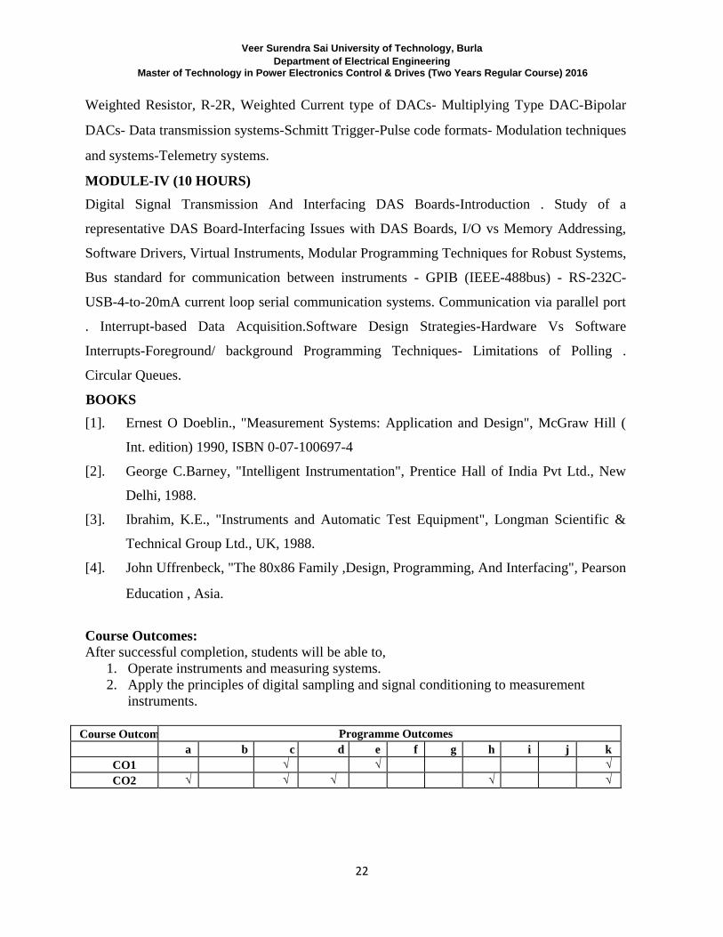
Course Outcomes:
After successful completion, students will be able to,
1. Operate instruments and measuring systems.
2. Apply the principles of digital sampling and signal conditioning to measurement
instruments.
Course Outcomes Programme Outcomes
a b c d e f g h i j k
CO1
√ √
√
CO2 √ √ √ √
√
Veer Surendra Sai University of Technology, Burla Department of Electrical Engineering
Master of Technology in Power Electronics Control & Drives (Two Years Regular Course) 2016
23
(1ST
SEMESTER) POWER ELCTRONICS & DRIVES LAB-I (0-0-6)
Course Objectives:
In this laboratory students will learn about the following points:
1. To prepare students to succeed in industry, technical profession, and to excel in
PhDprogramme.
2. able to use control system and simpower system tool boxes.
3. able to realize different converter circuits.
4. able to visualize input/output voltage/current waveforms.
5. able to learn use of PSPICE software for circuit analysis.
6. able to design and analyze any circuits, before going to design practical circuits.
7. able to solve circuit problem and debugging.
SYLLABUS
LIST OF EXPERIMENTS
1. Pspice simulation of single phase full converter using RL & E loads & single phase AC
voltage controller using RL & E loads 2. Pspice simulation of resonant pulse commutation circuit and buck chopper 3. Pspice simulation single phase inverter with PWM control 4. Simulation of Buck/Boost DC-DC converter using PSPICE 5. Simulation of SMPS using Pspice 6. Simulation of 3-phase bridge converter in MATLAB with R-L-E load 7. Simulation of 1-phase bridge converter in MATLAB
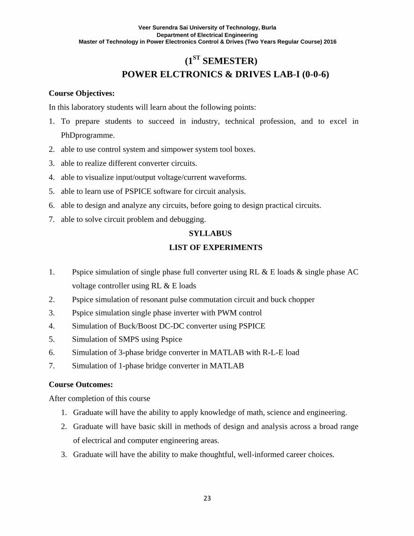
Course Outcomes:
After completion of this course
1. Graduate will have the ability to apply knowledge of math, science and engineering.
2. Graduate will have basic skill in methods of design and analysis across a broad range
of electrical and computer engineering areas.
3. Graduate will have the ability to make thoughtful, well-informed career choices.

Veer Surendra Sai University of Technology, Burla Department of Electrical Engineering
Master of Technology in Power Electronics Control & Drives (Two Years Regular Course) 2016
24
Mapping of Course Outcomes to Programme Outcomes
Course
Outcomes
Program Outcomes
a b c d e f g h i j k
CO1 √ √ √ √ √ √ √ √
CO2 √ √ √ √ √ √ √ √
CO3 √ √ √ √
Veer Surendra Sai University of Technology, Burla Department of Electrical Engineering
Master of Technology in Power Electronics Control & Drives (Two Years Regular Course) 2016
25
(2ND
SEMESTER) POWER ELECTRONIC DEVICES-II (3-1-0)
Course Objectives:
In this laboratory students will learn about the following points:
1. To prepare students to succeed in industry, technical profession, and to excel in PhD
programme.
2. able to use control system and sim power system tool boxes.
3. able to realize different power electronics components and its applications.
4. able to visualize input/output voltage/current waveforms.
5. able to learn use of PSPICE software for circuit analysis.
6. able to design and analyze any circuits, before going to design practical circuits.
7. able to solve circuit problem and debugging and ready to face the challenges.
SYLLABUS MODULE-I (10HOURS) Converters for Static Compensation . Standard Modulation Strategies - Programmed Harmonic
Elimination . Multi-Pulse Converters and Interface Magnetics . Multi-Level Inverters of Diode
Clamped Type and Flying Capacitor Type and suitable modulation strategies -Space Vector
Modulation - Minimum ripple current PWM method. Multi-level inverters of Cascade Type.
Current Regulated Inverter -Current Regulated PWM Voltage Source Inverters . Methods of
Current Control Hysteresis Control . Variable Band Hysteresis Control . Fixed Switching
Frequency Current Control Methods . Switching Frequency Vs accuracy of Current Regulation .
Areas of application of Current Regulated VSI . MODULE-II (10 HOURS) Switched Mode Rectifier - Operation of Single/Three Phase Bridges in Rectifier Mode . Control
Principles . Control of the DC Side Voltage, Voltage Control Loop. The inner Current Control
Loop. Special Inverter Topologies - Current Source Inverter . Ideal Single Phase CSI operation,
analysis and waveforms - Analysis of Single Phase Capacitor Commutated CSI. Series Inverters
. Analysis of Series Inverters . Modified Series Inverter . Three Phase Series Inverter MODULE-III (10 HOURS) Buck, Boost, Buck-Boost SMPS Topologies . Basic Operation- Waveforms - modes of
operation-Output voltage ripple Push-Pull and Forward Converter Topologies - Basic Operation .
Waveforms - Voltage Mode Control. Half and Full Bridge Converters . Basic Operation and
Waveforms- Fly back Converter .discontinuous mode operation . waveforms . Control -
Veer Surendra Sai University of Technology, Burla Department of Electrical Engineering
Master of Technology in Power Electronics Control & Drives (Two Years Regular Course) 2016
26
Continuous Mode Operation . Waveforms MODULE-IV (10 HOURS) Introduction to Resonant Converters . Classification of Resonant Converters . Basic Resonant
Circuit Concepts . Load Resonant Converter . Resonant Switch Converter . Zero Voltage
Switching Clamped Voltage Topologies . Resonant DC Link Inverters with Zero Voltage
Switching. High Frequency Link Integral Half Cycle Converter BOOKS [1]. Ned Mohan et.al: Power Electronics John Wiley and Sons [2]. Rashid: Power Electronics Prentice Hall India [3]. G.K.Dubey et.al: Thyristorised Power Controllers, Wiley Eastern Ltd.
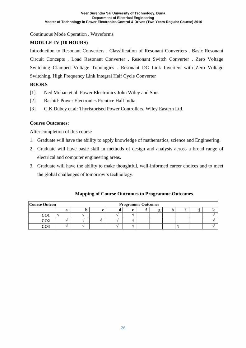
Course Outcomes:
After completion of this course
1. Graduate will have the ability to apply knowledge of mathematics, science and Engineering.
2. Graduate will have basic skill in methods of design and analysis across a broad range of
electrical and computer engineering areas.
3. Graduate will have the ability to make thoughtful, well-informed career choices and to meet
the global challenges of tomorrow’s technology.
Mapping of Course Outcomes to Programme Outcomes
Course Outcomes Programme Outcomes
a b c d e f g h i j k
CO1 √ √ √ √ √
CO2 √ √ √ √ √ √
CO3 √ √ √ √ √ √
Veer Surendra Sai University of Technology, Burla Department of Electrical Engineering
Master of Technology in Power Electronics Control & Drives (Two Years Regular Course) 2016
27
(2ND
SEMESTER) MACHINE DRIVES (3-1-0)
Course Objectives:
In this subject students will learn about the following points:
1. To make students familiar about the adjustable speed electric motor Drives through
conventional methods and various motor load characteristics.
2. To make understand the students about the application of power electronics converter for
adjustable speed drives to save the energy.
3. The students should understand the various power electronics converter used in DC
motor drive and application of voltage source and current source converter in induction
as well as synchronous motor.
4. To make students familiar with motor armature mmf in space distribution and control of
harmonics and its effect on motor.
5. To make understand the control system speed drive system by voltage and frequency
control method and soft starting if the induction as well as synchronous motor.
6. To acquire knowledge of vector control used in very precious application of induction
motors.
SYLLABUS MODULE-I (10 HOURS) Introduction to Motor Drives - Components of Power Electronic Drives - Criteria for selection of
Drive components - Match between the motor and the load - Thermal consideration - Match
between the motor and the Power Electronics converter - Characteristics of mechanical systems -
stability criteria
MODULE-II (10 HOURS) D.C Motor Drives - System model motor rating - Motor-mechanism dynamics - Drive transfer
function - Effect of armature current waveform - Torque pulsations - Adjustable speed dc drives
- Chopper fed and 1-phase converter fed drives - Effect of field weakening.
MODULE-III (10 HOURS) Induction Motor Drives - Basic Principle of operation of 3 phase motor - Equivalent circuit -
MMF space harmonics due to fundamental current - Fundamental spatial mmf distributions due
to time harmonics - Simultaneous effect of time and space harmonics - Speed control by varying
stator frequency and voltage - Impact of nonsinusoidal excitation on induction motors - Variable
frequency converter classifications - Variable frequency PWM-VSI drives - Variable frequency
square wave VSI drives - Variable frequency CSI drives - Comparison of variable frequency
drives - Line frequency variable voltage drives - Soft start of induction motors - Speed control by
static slip power recovery. - Vector control of 3 phase squirrel cage motors - Principle of
Veer Surendra Sai University of Technology, Burla Department of Electrical Engineering
Master of Technology in Power Electronics Control & Drives (Two Years Regular Course) 2016
28
operation of vector control-
MODULE-IV (10 HOURS) Synchronous Motor Drives - Introduction - Basic principles of synchronous motor operation
methods of control - operation with field weakening - load commutated inverter drives. BOOKS [1]. Ned Mohan, “Power Electronics”, et. al Wiley. [2]. G.K.Dubey&C.R.Kasaravada, “Power Electronics & Drives”, Tata McGraw Hill. [3]. W.Shephered, L N HulleyCambride, “Power Electronics & Control of Motor”, University
Press.
[4]. Dubey, “Power Electronics Drives”, Wiley Eastern
[5]. R. Krishnan , “ Electric Motor Drives : Modeling , Analysis & Control ” , ‘ Prentice Hall
’ , New Jersey, 2001.
[6]. M.H.Rashid Power Electronics”, (P.H.I.Edition)
[7]. S.K.Pillai, Jhon Willy & Sons,” A first Course on Electrical Drives”
Course Outcomes:
After completion of this course
CO1: Graduate will demonstrate the control techniques during starting, running and breaking
periods of the drive systems.
CO2:Graduate will able to know the saving of electric power by power electronics converter
techniques.
CO3: Graduate will able to know with the adjustable speed drives of induction and synchronous
motor through voltage and frequency control by PWM-VSI and CSI methods.
CO4: Students will demonstrate the adjustable speed drives of DC motors through DC-DC
Chopper and control rectifier methods.
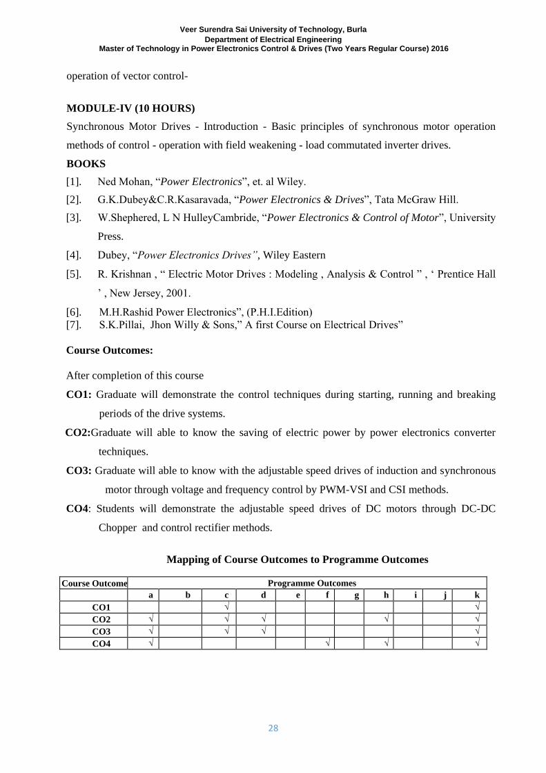
Mapping of Course Outcomes to Programme Outcomes
Course Outcomes Programme Outcomes
a b c d e f g h i j k
CO1
√
√
CO2 √ √ √ √
√
CO3 √ √ √ √
CO4 √
√ √ √
Veer Surendra Sai University of Technology, Burla Department of Electrical Engineering
Master of Technology in Power Electronics Control & Drives (Two Years Regular Course) 2016
29
(2ND
SEMESTER)
FACTS MODELING CONTROL & APPLICATION (3-1-0)
Course Objectives:
1. Understand the importance of controllable parameters and benefits of FACTS controllers in
power system operation.
2. Know the significance of different types of FACTS controller and their modelling for power
system control.
3. Understand the application of various FACTS controller for improvement of power system
performance.
SYLLABUS MODULE-I (10 HOURS) FACTS concepts and general system considerations: Power flow in AC system, transintstabiltiy
and dynamic stability, basic description of FACTS controllers, brief review of voltage sourced
converter and current sourced converter, modeling philosophy
Static var compensator (SVC and STATCOM): objectives of shunt compensation, methods of
controllable Var Generation, regulation slope, transfer function, V-I and V-Q characteristics,
transient stability enhancement, var reserve control, conventional power flow models, shunt
variable susceptance model, firing angle model, transient stability model, voltage magnitude
control using SVC & STACOM, Application example MODULE-II (10 HOURS) Static Series compensators (TCSC and SSSC): objectives of series compensation, improvements
of voltage and transient stability, power oscillation damping, subsynchronous damping,
transmittable power and transmittable angle charcteristics, control range, conventional power
flow models, variable series impedance model, firing angle model, transient stability model,
active power flow control using TCSC & SSSC, Application example MODULE-III (10 HOURS) Static voltage and phase angle regulator (TCVR and TCPAR): objectives of voltage and phase
angle regulators, approaches to TCVR and TCPAR, switching converter based voltage and pahse
angle regulators Unified power flow controller: Basic operating principles, transmission control, independent real
and reactive power flow control, power flow models, transient stability model, control structure,
basic control system for P and Q control, dynamic performance, Application example
Veer Surendra Sai University of Technology, Burla Department of Electrical Engineering
Master of Technology in Power Electronics Control & Drives (Two Years Regular Course) 2016
30
MODULE-IV (10 HOURS) Breif control studies such as Steady state analysis and control, EMTP studies, power oscillation
stability analysis and control, transient stability control BOOKS [1]. Y. H. Songs, A. T. Johns, “Flexible AC Transmission Systems”, IEE Press, 1999 [2]. N. G. Hingorani, L. Gyugyi, “Understanding FACTS”, IEEE Press, Indian Edition, 2001. [3]. E. Acha, “FACTS: modelling and simulation in power networks”, John Wiley & Sons,
2004.
[4]. K. R. Padiyar , “ FACTS Controllers in Power Transmission & Distribution ” , New Age
International Publishers , 2014
[5]. Vijay K. Sood , “ HVDC and FACTS Controller: Applications of Static Converters in
Power Systems” , Kluwer Power Electronics & Power System Series , 2006
Course Outcomes:
1. An ability to apply knowledge of FACTS Controllers.
2. An ability to design a Compensators within realistic constraints.
3. An ability to identify, model, and solve real network problems with FACTS controllers.
4. The broad education necessary to understand the impact of engineering solutions in a global
perspective.
5. A knowledge of recent trend in FACTS controllers and application of FACTS controllers.
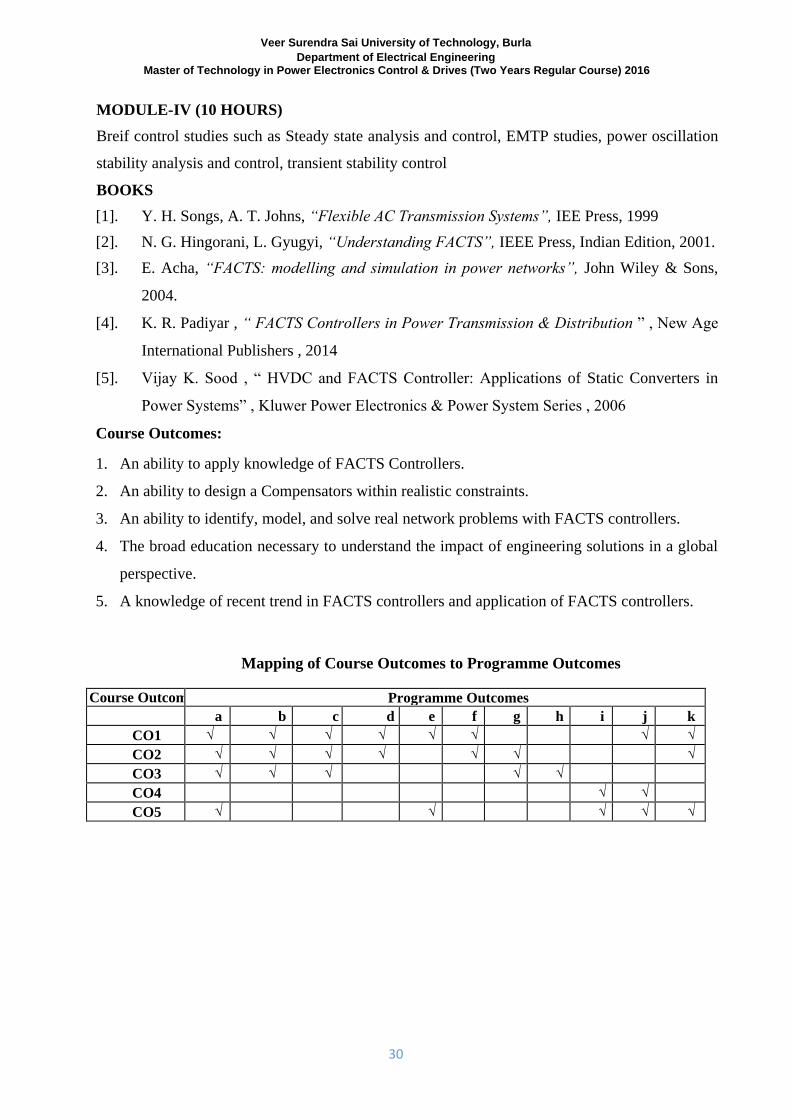
Mapping of Course Outcomes to Programme Outcomes
Course Outcomes Programme Outcomes
a b c d e f g h i j k
CO1 √ √ √ √ √ √ √ √
CO2 √ √ √ √ √ √ √
CO3 √ √ √ √ √
CO4 √ √
CO5 √ √ √ √ √
Veer Surendra Sai University of Technology, Burla Department of Electrical Engineering
Master of Technology in Power Electronics Control & Drives (Two Years Regular Course) 2016
31
(2ND
SEMESTER) DIGITAL SIMULATION OF POWER ELECTRONIC SYSTEMS
(3-1-0)
Course Objectives :
1. Device modeling
2. State Space modeling
3. PSpice A/D simulation
4. PSpice Schematic simulation
SYLLABUS MODULE-I (10 HOURS) Principles of Modeling Power Semiconductor Devices - Macromodels versus Micromodels -
Thyristor model - Semiconductor Device modelled as Resistance, Resistance-Inductance and
Inductance-Resistance-Capacitance combination - Modelling of Electrical Machines - Modelling
of Control Circuits for Power Electronic Switches. Computer Formulation of Equations for
Power Electronic Systems - Review of Graph Theory as applied to Electrical Networks -
Systematic method of Formulating State Equations - Computer Solution of State Equations -
Explicit Integration method - Implicit Integration method. MODULE-II (10 HOURS) Circuit Analysis Software MicroSimPSpice A/D - Simulation Overview - Creating and Preparing
a Circuit for Simulation - Simulating a Circuit with PSpice A/D - Displaying Simulation Results
- PSpice A/D Analyses - Simple Multi-run Analyses - Statistical Analyses - Simulation
Examples of Power Electronic systems.
MODULE-III (10 HOURS) MicroSim PSpice A/D - Preparing a Schematic for Simulation - Creating Symbols - Creating -
Models - Analog Behavioural Modeling - Setting Up and Running analyses - Viewing Results -
Examples of Power Electronic Systems.
MODULE-IV (10 HOURS) Design Creation and Simulation with Saber Designer - Placing the Parts - Editing the Symbol -
Properties - Wiring the Schematic - Modifying Wire Attributes - Performing a Transient and DC
Analysis - Placing Probes in the Design - Performing AC Analysis and Invoking SaberScope -
Analysing waveforms with SaberScope - Performing Measurements on a waveform - Varying a
Veer Surendra Sai University of Technology, Burla Department of Electrical Engineering
Master of Technology in Power Electronics Control & Drives (Two Years Regular Course) 2016
32
Parameter - Displaying the Parameter Sweep Results - Measuring a Multi-Member Waveform -
Simulation Examples of Power Electronic Systems. BOOKS [1]. V.Rajagopalan, ”Computer Aided Analysis of Power Electronic Systems”, Marcel Dekker,
Inc. [2]. MicroSimPSpice A/D and Basics+: Circuit Analysis Software, User's Guide, MicroSim
Corporation. [3]. MicroSim Schematics: Schematic Capture Software, User's Guide, MicroSim
Corporation.
Course Outcomes :
1. 100% result showing learning of all objectives
2. One M Tech thesis is produced on PSpice Schematic simulation
Over all students have learnt simulation of power electronics system.
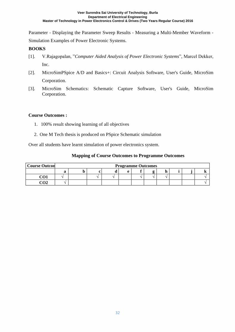
Mapping of Course Outcomes to Programme Outcomes
Course Outcomes Programme Outcomes
a b c d e f g h i j k
CO1 √ √ √ √ √ √ √
CO2 √ √
Veer Surendra Sai University of Technology, Burla Department of Electrical Engineering
Master of Technology in Power Electronics Control & Drives (Two Years Regular Course) 2016
33
(2ND
SEMESTER) (ELECTIVE-II)
POWER QUALITY (3-1-0)
Course Objectives:
The objective of this course is to
1. Provide general concept of power quality issues.
1. The main reasons of getting the power quality down.
2. The various bench marks to be followed in maintaining the power quality,
3. The power quality issues with the increase use of power electronics as well as
microprocessor based devices in modern power system.
4. To know the practical problems in modern power systems includes the distribution
generation.
5. Help the student understand the monitoring of power quality issues.
SYLLABUS MODULE-I (10 HOURS) PQ Definitions and Standards General Classification of PQ Phenomena IEEE and IEC PQ
Standards, PQ Monitoring and Measuring Available monitoring techniques and their drawbacks
Commercial power quality monitors, Power quality monitors sensitivity PQ Problems
Identification, PQ Phenomena Classification Identification and localization of PQ problems
Different PQ classification techniques and case studies MODULE-II (10 HOURS) Harmonic Sources, Effects, Analysis, and Modeling, Harmonic Distortion Mitigation Voltage vs.
Current Distortion, Harmonics vs. Transients Harmonic Sources from Commercial and Industrial
Loads, Time domain versus frequency domain Different Harmonic filters (passive, active and
hybrid); and case studies
MODULE-III (10 HOURS) Voltage Sag, Swell and Interruptions, Transient Over-voltages, Sources of Sags and
Interruptions, Fundamental Principles of Protection, Motor-Starting Sags, Utility System Fault-
Clearing. Issues, and Case Studies, Sources of Transient Overvoltages; Principles of Overvoltage
Protection and Switching Transient Problems with Loads MODULE-IV (10 HOURS)
Veer Surendra Sai University of Technology, Burla Department of Electrical Engineering
Master of Technology in Power Electronics Control & Drives (Two Years Regular Course) 2016
34
Voltage Flicker, Voltage Unbalance, Voltage Regulation Sources of voltage flicker; Effects and
mitigation techniques Sources of voltage unbalance; Effects and mitigation techniques Devices
for Voltage Regulation; Utility Voltage Regulator Application and End-User Capacitor
Application BOOKS [1]. R. Dugan, M. Mc Granaghan, S. Santoso and H. Beaty, Electrical Power System Quality,
Second Edition, McGraw-Hill, 2002, ISBN 0-07-138622-X.
[2]. J. Arrillaga, B. Smith, N. Watson and A. Wood, Power System Harmonic Analysis, John
Wiley, 1997, ISBN 0-471-97548-6. [3]. Understanding Power Quality Problems by Math H. Bollen [4]. J. Arrillaga, .Power System Quality Assessment., John wiley, 2000
[5]. R. SastryVedam , M. S. Sarma , “ Power Quality: VAR Compensation in Power System ”
CRC Press , Taylor and Francis group , 2008
Course Outcomes:
When the students have passed the course, they shall be able to
1. Understand the reasons for increased concern for power quality issues in power systems.
2. Follow the benchmarking process in power quality sector.
3. To analyses and solve the issues in power quality improvement.
4. To apply technology in solving the problems of power quality.
5. To solve the problems when there is use of distribution generation.
6. Understand the various monitoring methods used in power quality issues.
7. Plan of controlling the power quality issues.
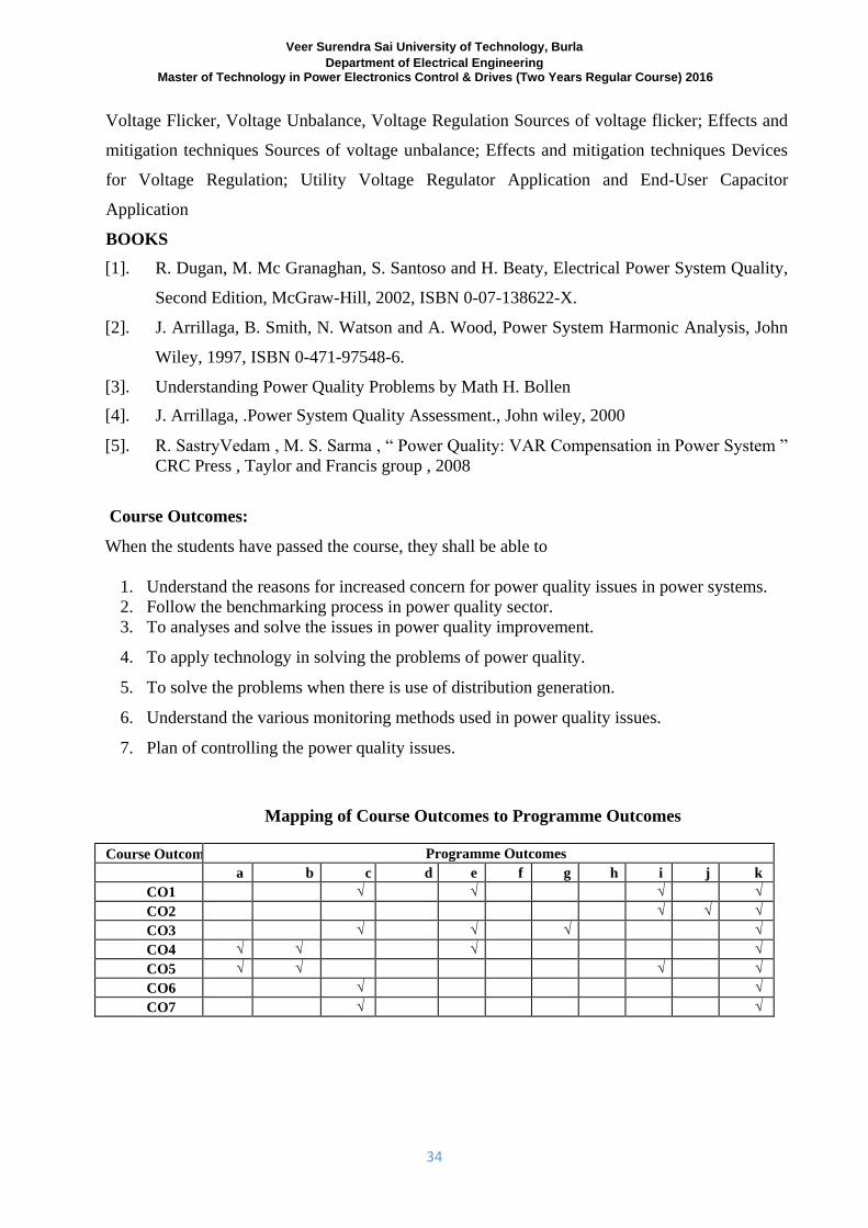
Mapping of Course Outcomes to Programme Outcomes
Course Outcomes Programme Outcomes
a b c d e f g h i j k
CO1 √ √ √ √
CO2 √ √ √
CO3 √ √ √ √
CO4 √ √ √ √
CO5 √ √ √ √
CO6 √ √
CO7 √ √
Veer Surendra Sai University of Technology, Burla Department of Electrical Engineering
Master of Technology in Power Electronics Control & Drives (Two Years Regular Course) 2016
35
(2ND
SEMESTER) (ELECTIVE-II)
NON LINEAR SYSTEM THEORY (3-1-0)
Course Objectives:
The objectives of the course is to make the students able
1. To understand the fundamentals of nonlinear systems.
2. To apply mathematical analysis of nonlinear systems.
3. To understand stability of nonlinear system.
SYLLABUS MODULE-I (10 HOURS) Non Linear Systems: Ordinary differential equation (ODE) systems, Differential & algebraic equation (DAE) systems,
Equilibrium points, Limit cycles, pointcare maps, monodromy matrices, dynamic manifolds,
region of attraction, Lyapunov stability,
MODULE-II (10 HOURS) Numerical Methods: Newton Raphson, eigen value computation, initial value problems (IVP)
and boundary value problems (BVP) Definitions of local and global bifurcations saddle node bifurcations, transcritical bifurcations,
pitchforks and Hopf bifurcations, Limit induced bifurcations, center manifolds Normal forms: Lyapunov Schmidt reduction DAE systems: bifurcations transversality conditions and singularity induced bifurcations MODULE-III (10 HOURS) Singular bifurcations computations: continuation methods and direct methods, optimization
techniques Hopf bifurcations computations: continuation methods and direct methods Bifurcations of limit
cycle: definition and computation
MODULE-IV (10 HOURS) Chaotic Behavior: Definition and examples of continuous and discrete (fractal) strange attractors. Mechanisms that lead to chaos: Torus bifurcations period doubling, intermittency, instant chaos,
fractal, dimensions, Lyapunov exponents, power spectra.
Veer Surendra Sai University of Technology, Burla Department of Electrical Engineering
Master of Technology in Power Electronics Control & Drives (Two Years Regular Course) 2016
36
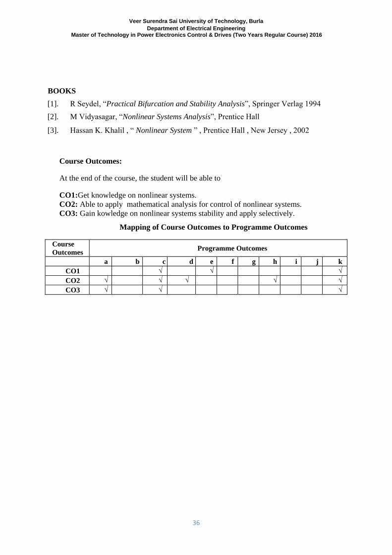
BOOKS [1]. R Seydel, “Practical Bifurcation and Stability Analysis”, Springer Verlag 1994 [2]. M Vidyasagar, “Nonlinear Systems Analysis”, Prentice Hall
[3]. Hassan K. Khalil , “ Nonlinear System ” , Prentice Hall , New Jersey , 2002
Course Outcomes:
At the end of the course, the student will be able to
CO1:Get knowledge on nonlinear systems.
CO2: Able to apply mathematical analysis for control of nonlinear systems.
CO3: Gain kowledge on nonlinear systems stability and apply selectively.
Mapping of Course Outcomes to Programme Outcomes
Course
Outcomes Programme Outcomes
a b c d e f g h i j k
CO1
√ √
√
CO2 √ √ √ √
√
CO3 √ √ √
Veer Surendra Sai University of Technology, Burla Department of Electrical Engineering
Master of Technology in Power Electronics Control & Drives (Two Years Regular Course) 2016
37
(2ND
SEMESTER)
(ELECTIVE-II)
ADVANCED CONTROL OF DRIVES (3-1-0)
Course Objectives:
1. The purpose of this course is to introduce the various modelling concepts in vector and
field-oriented control for induction and synchronous drives.
2. Concept of Parameter sensitivity, selection of flux level, field weakening and parameter
detuning in steady-state operation is necessary to be learnt.
3. The students should be capable to principles for speed sensor-less control and their
application in drives.
4. The purpose is to give up-to-date knowledge for designing the drives.
SYLLABUS MODULE-I (10 HOURS) Principles for vector and field-oriented control-Complex-valued dq-model of induction
machines. Turns ratio and modified dq-models. Principles for field-oriented vector control of ac
machines. Current controllers in stationary and synchronous coordinates. Rotor-flux oriented
control of current-regulated induction machine - Dynamic model of IM in rotor-flux coordinates.
Indirect rotor-flux oriented control of IM - Direct rotor-flux oriented control of IM.- Methods to
estimation of rotor-flux MODULE-II (10 HOURS) Generalized flux-vector control using current- and voltage decoupling networks- Generalized
flux-vector oriented control. Current and voltage decoupling networks. Air gap-oriented control.
Voltage-fed vector control. Stator-flux oriented vector control.
MODULE-III (10 HOURS) Parameter sensitivity, selection of flux level, and field weakening - Parameter detuning in
steady-state operation. Parameter detuning during dynamics. Selection of flux level. Control
strategies for used in the over-speed region .
MODULE-IV (10 HOURS) Principles for speed sensor-less control - Principles for speed sensor-less control. Sensor-less
methods for scalar control. Sensor-less methods for vector control .Introduction to observer-
based techniques
Veer Surendra Sai University of Technology, Burla Department of Electrical Engineering
Master of Technology in Power Electronics Control & Drives (Two Years Regular Course) 2016
38
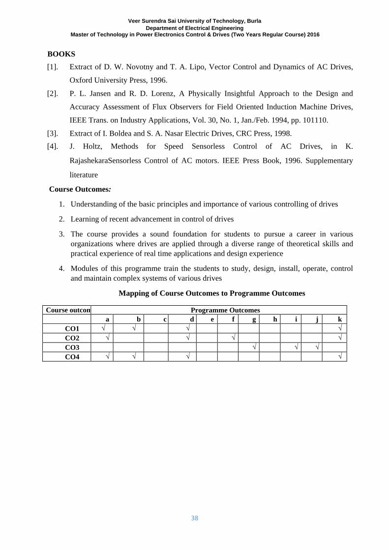
BOOKS [1]. Extract of D. W. Novotny and T. A. Lipo, Vector Control and Dynamics of AC Drives,
Oxford University Press, 1996. [2]. P. L. Jansen and R. D. Lorenz, A Physically Insightful Approach to the Design and
Accuracy Assessment of Flux Observers for Field Oriented Induction Machine Drives,
IEEE Trans. on Industry Applications, Vol. 30, No. 1, Jan./Feb. 1994, pp. 101110. [3]. Extract of I. Boldea and S. A. Nasar Electric Drives, CRC Press, 1998. [4]. J. Holtz, Methods for Speed Sensorless Control of AC Drives, in K.
RajashekaraSensorless Control of AC motors. IEEE Press Book, 1996. Supplementary
literature
Course Outcomes:
1. Understanding of the basic principles and importance of various controlling of drives
2. Learning of recent advancement in control of drives
3. The course provides a sound foundation for students to pursue a career in various
organizations where drives are applied through a diverse range of theoretical skills and
practical experience of real time applications and design experience
4. Modules of this programme train the students to study, design, install, operate, control
and maintain complex systems of various drives
Mapping of Course Outcomes to Programme Outcomes
Course outcomes Programme Outcomes
a b c d e f g h i j k
CO1 √ √ √ √
CO2 √ √ √ √
CO3 √ √ √
CO4 √ √ √ √
Veer Surendra Sai University of Technology, Burla Department of Electrical Engineering
Master of Technology in Power Electronics Control & Drives (Two Years Regular Course) 2016
39
(2ND
SEMESTER)
(ELECTIVE-II)
SWITCHED MODE AND RESONANT CONVERTERS (3-1-0)
Course Objectives:
1. Students will learn basic operation, waveform, modes of operation and switching losses
of Buck,Boost,and Buck-Boost converter.
2. Students will understand the Voltage control mode and Current control mode of SMPS .
3. Students will understand State Space Averaging and Linearisation and discontinuous
mode of operation of SMPS .
4. Students will understand the EMI Filtering at Input and Output and Effect of EMI Filter
on SMPS Control Dynamics.
5. Students will understand the introduction and classification of resonant converter.
6. Students will understand Zero Voltage Switching Clamped Voltage Topologies and
Resonant DC Link Inverters with Zero Voltage Switching.
SYLLABUS
MODULE-I (10 HOURS) Buck, Boost, Buck-Boost SMPS Topologies . Basic Operation- Waveforms - modes of operation
- switching stresses - switching and conduction losses - optimum switching frequency - practical
voltage, current and power limits - design relations - voltage mode control principles. Push-Pull
and Forward Converter Topologies - Basic Operation . Waveforms - Flux Imbalance Problem
and Solutions - Transformer Design -Output Filter Design -Switching Stresses and Losses -
Forward Converter Magnetics --Voltage Mode Control. Half and Full Bridge Converters . Basic
Operation and Waveforms-Magnetics . Output Filter . Flux Imbalance . Switching Stresses and
Losses . Power Limits . Voltage Mode Control. FlybackConverter .discontinuous mode
operation . waveforms .Control . Magnetics- Switching Stresses and Losses . Disadvantages -
Continuous Mode Operation .Waveforms .Control . Design Relations. MODULE-II (10 HOURS) Voltage Mode Control of SMPS . Loop Gain and Stability Considerations . Shaping the Error
Amp frequency Response . Error Amp Transfer Function .Transconductance Error Amps . Study
of popular PWM Control Ics (SG 3525,TL 494,MC34060 etc.)Current Mode Control of SMPS .
Current Mode Control Advantages . Current Mode Vs Voltage Mode . Current Mode
Deficiencies . Slope Compensation . Study of a typical Current Mode PWM Control IC UC3842.
Veer Surendra Sai University of Technology, Burla Department of Electrical Engineering
Master of Technology in Power Electronics Control & Drives (Two Years Regular Course) 2016
40
MODULE-III (10 HOURS) Modeling of SMPS . State Space Averaging and Linearisation. State Space Averaging
Approximation for Continuity . Discontinuous Conduction Modes . Small Signal
Approximation- General Second Order Linear Equivalent Circuits . The DC Transformer .
Voltage Mode SMPS Transfer Function . General Control Law Considerations . Source to State
Transfer Function . Source to Output Transfer Function .Stability . Loop Compensation EMI
Generation and Filtering in SMPS - Conducted and Radiated Emission Mechanisms in SMPS .
Techniques to reduce Emissions . Control of Switching Loci . Shielding and Grounding . Power
Circuit Layout for minimum EMI . EMI Filtering at Input and Output . Effect of EMI Filter on
SMPS Control Dynamics MODULE-IV (11 HOURS) Introduction to Resonant Converters . Classification of Resonant Converters . Basic Resonant
Circuit Concepts . Load Resonant Converter . Resonant Switch Converter . Zero Voltage
Switching Clamped Voltage Topologies . Resonant DC Link Inverters with Zero Voltage
Switching . High Frequency Link Integral Half Cycle Converter.
BOOKS [1]. Abraham I Pressman : Switching Power Supply Design. McGraw Hill Publishing
Company.
[2]. Daniel M Mitchell : DC-DC Switching Regulator Analysis. McGraw Hill Publishing
Company
[3]. Ned Mohan et.al : Power Electronics.John Wiley and Sons.
[4]. OtmarKilgenstein: Switched Mode Power Supplies in Practice. John Wiley and Sons.
[5]. Keith H Billings: Handbook of Switched Mode Power Supplies. McGraw Hill Publishing
Company.
Course Outcomes:
When the students have passed the course, they shall be able to
1. To introduce and clasify different forms of resonant dc-dc converter.
2. Use of vector analysis, different topologies and control mechanism of SMPS.
3. To analyse and know the high frequency and zero switching.
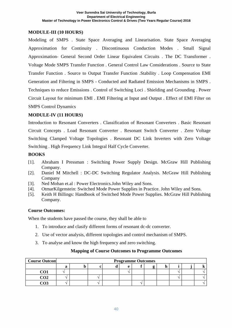
Mapping of Course Outcomes to Programme Outcomes
Course Outcomes Programme Outcomes
a b c d e f g h i j k
CO1 √ √ √ √
CO2 √ √ √ √
CO3 √ √ √ √
Veer Surendra Sai University of Technology, Burla Department of Electrical Engineering
Master of Technology in Power Electronics Control & Drives (Two Years Regular Course) 2016
41
(2ND
SEMESTER) POWER ELCTRONICS & DRIVES LAB-II (0-0-6)
Course Objectives:
In this laboratory students will learn about the following points:
1. To prepare students to succeed in industry, technical profession, and to excel in PhD
programme.
2. able to use control system and simpower system tool boxes.
3. able to realize different power electronics components and its applications.
4. able to visualize input/output voltage/current waveforms.
5. able to learn use of PSPICE software for circuit analysis.
6. able to design and analyze any circuits, before going to design practical circuits.
7. able to solve circuit problem and debugging and ready to face the challenges.
SYLLABUS
LIST OF EXPERIMENTS
1. Analysis of Dual Converter fed DC motor Drive 2. Chopper Fed DC motor Drive 3. Performance study of Stator Voltage controlled Induction Motor Drive 4. Analysis of Vector Controlled Induction Motor Drive 5. IGBT based Three Phase inverter 6. IGBT based single phase PWM Inverter 7. Speed control of DC motor using three phase fully controlled converter 8. Three phase half wave cycloconverter 9. Simulation of power electronics systems using PSPICE 10. Modeling and simulation of electric Drives using MATLAB 11. Operation of Cycloconverter on R-L and Motor Load.
12. Speed control of induction motor by operation of cycloconverter on R-L and motor load.
Course Outcomes:
After completion of this course
1. Graduate will have the ability to apply knowledge of mathematics, science and Engineering.
2. Graduate will have basic skill in methods of design and analysis across a broad range of
electrical and computer engineering areas.
Veer Surendra Sai University of Technology, Burla Department of Electrical Engineering
Master of Technology in Power Electronics Control & Drives (Two Years Regular Course) 2016
42
3. Graduate will have the ability to make thoughtful, well-informed career choices and to meet
the global challenges of tomorrow’s technology.
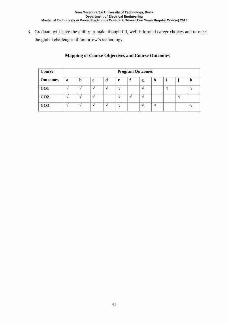
Mapping of Course Objectives and Course Outcomes
Course
Outcomes
Program Outcomes
a b c d e f g h i j k
CO1 √ √ √ √ √ √ √ √
CO2 √ √ √ √ √ √ √
CO3 √ √ √ √ √ √ √ √