Embed Size (px)
Citation preview

PRE-FEASIBILITY REPORT
FOR
Exploration and Development Project in
PKGM-1 (RAVVA) Block in East Godavari
District, Andhra Pradesh
VEDANTA LIMITED
(CAIRN OIL & GAS)
January 2018

January 2018 Vedanta Limited (Cairn Oil & Gas)
I
CONTENTS
0 EXECUTIVE SUMMARY 1
0.1 INTRODUCTION 1
0.2 JUSTIFICATION & BRIEF DESCRIPTION OF THE PROPOSED PROJECT 2
0.3 PROJECT PROPOSAL 2
0.4 NEED OF THE PROJECT AND ITS IMPORTANCE FOR THE COUNTRY 3
0.5 PROJECT SCHEDULE AND COST ESTIMATE 3
0.6 EMPLOYMENT GENERATION 3
1 PROJECT DESCRIPTION 4
1.1 TYPE OF PROJECT INCLUDING INTERLINKED AND INTERDEPENDENT PROJECTS, IF
ANY 4
1.2 BLOCK LOCATION 4
1.3 EXISTING OFFSHORE FACILITIES 5
1.3.1 Wells Drilled in Block 5
1.3.2 Pipeline Network 5
1.4 PROPOSED PROJECT DESCRIPTION 8
1.4.1 Development Wells 9
1.4.2 Exploratory Wells 9
1.5 JUSTIFICATION OF THE PROJECT SITE 12
1.6 SET-UP PROPOSED FOR THE ONSHORE WELLS 12
1.6.1 Site Preparatory Works 13
1.7 PROPOSED DEVELOPMENT IN OFFSHORE REGION OF THE BLOCK 16
1.7.2 Drilling mud system 18
1.8 WASTES & EMISSIONS 22
1.9 CHANGES IN PRODUCTION PROFILE AND ADEQUACY ASSESSMENT OF EXISTING
INFRASTRUCTURE 24
2 SITE ANALYSIS 27
2.1 CONNECTIVITY 27

January 2018 Vedanta Limited (Cairn Oil & Gas)
II
2.1.1 By Road 27
2.1.2 By Rail 27
2.1.3 By Air 27
2.1.4 By Sea 27
2.1.5 From Ravva Terminal 27
2.2 LAND FORM, LAND USE AND LAND OWNERSHIP 27
2.3 TOPOGRAPHY 28
2.4 CLIMATE 28
2.5 ECOLOGICAL SENSITIVITY 29
2.6 SOCIAL INFRASTRUCTURE 30
3 PLANNING BRIEF 31
3.1 PLANNING CONCEPT 31
4 PROJECT SCHEDULE & COST ESTIMATES 32
4.1 PROJECT SCHEDULE 32
4.2 ESTIMATED PROJECT COST 32
5 ANALYSIS OF PROPOSALS 33
5.1 FINANCIAL BENEFITS 33
5.2 SOCIAL BENEFITS 33
5.3 CSR ACTIVITIES 33

January 2018 Vedanta Limited (Cairn Oil & Gas)
1
0 EXECUTIVE SUMMARY
0.1 INTRODUCTION
Vedanta Limited (Cairn Oil & Gas)1 is one of the largest independent oil and
gas exploration and production companies in India. On behalf of Ravva Joint
Venture, Vedanta Limited (Cairn Oil & Gas) (erstwhile Cairn India Limited)
has been carrying out oil and gas operations in PKGM-1 Block located in the
Bay of Bengal in the Krishna-Godavari Basin near Surasaniyanam Village,
Uppalaguptam Mandal in East Godavari District, Andhra Pradesh.
Oil and Gas exploration and development activities in the PKGM-1 Block (also
referred to as Ravva Field or Ravva Block) are being taken up as part of
existing Production Sharing Contract signed for PKGM-1 Block with the
Ministry of Petroleum and Natural Gas through Directorate General of
Hydrocarbons, Government of India. The Block has an area of 331.26 sq. km
(km2).
The oil & gas field was discovered in 1988 by ONGC (Oil and Natural Gas
Corporation). On 28th October, 1994 when the Production Sharing Contract
(PSC) was signed, the offshore facilities included 4 wells, 2 platforms and 2
pipelines for production of 3,000 Barrels of Oil per day (BOPD) with an
onshore processing capacity of 8,600 BOPD. The Ravva JV commenced
operations in 1995 and over the years increased production capacity and
upgraded facilities. The operatorship of the field was transferred in 1995 to
Command Petroleum (India) Pty Ltd which was subsequently in 1997 was
transferred to Cairn Energy India Pty Limited (CEIL).
Vedanta Ltd (Cairn Oil & Gas) is the Operator of Ravva Joint Venture
comprising of Oil & Natural Gas Corporation Limited (ONGC), Vedanta Ltd
(Cairn Oil and Gas), Videocon Petroleum Ltd. (VPL) and Ravva Oil Singapore
Pty. Ltd. (ROS) as per the Table 1.1 of participating interests.
Table 0.1 JV Parties & their Participating Interest
Ravva Joint Venture Partners Participating Interest
Oil and Natural Gas Corporation Ltd. 40.0%
Vedanta Limited (Cairn Oil & Gas) [erstwhile Cairn India Limited] 22.5%
Videocon Petroleum Ltd 25.0%
Ravva Oil (Singapore) Pte Ltd 12.5%
Currently, within PKGM-1 Block, there exist 8 oil and gas platforms. Six
platforms (RA, RB, RC, RD, RE and RF) are meant for crude oil production
while two of them are natural gas producing platforms (RG and RH).
Additional new offshore platform termed as RI Platform will be set up as per
1 Cairn India Ltd. got merged with Vedanta Limited with effect from 11th April, 2017
January 2018 Vedanta Limited (Cairn Oil & Gas)
2
approval obtained through prior Environmental Clearance dated 23 Feb 2015
and CRZ Clearance dated 24 April 2017.
Within the PKGM-1 Block, there exist 55 wells of which 6 are self-flow
producing, 16 are gas lift wells and 9 are injectors spread over on 8 well head
platforms, inter-connecting pipelines, land terminal near Surasaniyanam
Village (with oil and gas processing and water injection facilities), Single Point
Mooring (SPM), Shuttle Tankers and Export pipelines for transport of crude.
Oil and Gas from offshore wells are routed through subsea pipelines to
onshore terminal located at Surasaniyanam Village, East Godavari District,
Andhra Pradesh.
0.2 JUSTIFICATION & BRIEF DESCRIPTION OF THE PROPOSED PROJECT
Over the years due to aging of the field, production of oil and gas has been
declined. The on-shore processing facility though has APPCB approved
capacity to produce 50,000 barrels of oil per day (BOPD) crude oil and 2.32
million standard cubic meter per day (MMSCMD) of natural gas is presently
producing ~ 15,000 BOPD of crude oil and ~1.4 MMSCMD of natural gas.
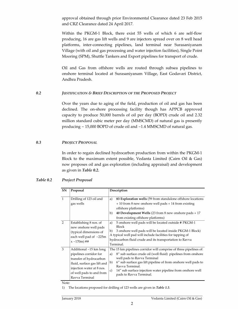
0.3 PROJECT PROPOSAL
In order to regain declined hydrocarbon production from within the PKGM-1
Block to the maximum extent possible, Vedanta Limited (Cairn Oil & Gas)
now proposes oil and gas exploration (including appraisal) and development
as given in Table 0.2.
Table 0.2 Project Proposal
SN Proposal Description
1 Drilling of 123 oil and
gas wells
a) 83 Exploration wells (59 from standalone offshore locations
+ 10 from 8 new onshore well pads + 14 from existing
offshore platforms)
b) 40 Development Wells (23 from 8 new onshore pads + 17
from existing offshore platforms)
2 Establishing 8 nos. of
new onshore well pads
(typical dimensions of
each well pad of ~225m
x ~170m) ##
a) 5 onshore well pads will be located outside # PKGM-1 Block
b) 3 onshore well pads will be located inside PKGM-1 Block) A typical well pad will include facilities for tapping of
hydrocarbon fluid crude and its transportation to Ravva
Terminal.
3 Additional ~15 km long
pipelines corridor for
transfer of hydrocarbon
fluid, surface gas lift and
injection water at 8 nos.
of well pads to and from
Ravva Terminal
The 15 km pipelines corridor will comprise of three pipelines of:
a) 8” sub surface crude oil (well fluid) pipelines from onshore well pads to Ravva Terminal
b) 6” sub surface gas lift pipeline of from onshore well pads to Ravva Terminal.
c) 14” sub surface injection water pipeline from onshore well pads to Ravva Terminal.
Note:
1) The locations proposed for drilling of 123 wells are given in Table 1.5.

January 2018 Vedanta Limited (Cairn Oil & Gas)
3
2) # For setting up of five new onshore pads outside the PKGM-1 Block i.e. within ONGC
PML to drill wells and tap hydrocarbon resources from within PKGM-1 Block. In this
regard, Vedanta Limited (Cairn Oil & Gas) has already received concurrence from ONGC
on drilling of wells from onshore well pads to be located outside the PKGM-1 Block. In this
regard, Vedanta Limited (Cairn Oil & Gas) on behalf of the Ravva JV has applied for
approval from Directorate General of Hydrocarbons (DGH), Ministry of Petroleum &
Natural Gas.
3) ##The above given each onshore well pad dimensions represent a typical size of 225 m x
170 m, however, configuration may change depending upon the land availability.
0.4 NEED OF THE PROJECT AND ITS IMPORTANCE FOR THE COUNTRY
The hydrocarbons sector plays vital role in the economic growth of the
country. With the ever increasing gap between the demand and supply in the
hydrocarbons, the scenario is a challenge for India. India depends on
imported crude to meet 75- 80% of its rapidly growing demand for petroleum
products. The hydrocarbon resources available in the Ravva (PKGM-1) Block
is of immense importance for the country and will help in the growth of the
economy and stride to reduce gap of crude oil imports versus self-sufficiency.
The enhanced production will benefit the country by reducing the import bill
and save foreign exchange and contribute to annual revenue to the
Government of India.
0.5 PROJECT SCHEDULE AND COST ESTIMATE
Vedanta Ltd (Cairn Oil & Gas) has planned to develop the available
hydrocarbon resources from the PKGM-1 Block in next 10 years.
The cost of the project is estimated to be ~ INR 7,924 Crores.
0.6 EMPLOYMENT GENERATION
As the proposed exploration and development drilling project does not
anticipate increase in the operations crew. There would however be
employment generation during construction of well pads, drilling and laying
of pipelines. Wherever possible, engagement of local contractors and workers
during the project phase will be preferred.

January 2018 Vedanta Limited (Cairn Oil & Gas)
4
1 PROJECT DESCRIPTION
1.1 TYPE OF PROJECT INCLUDING INTERLINKED AND INTERDEPENDENT PROJECTS, IF ANY
There are no interlinked or interdependent projects.
1.2 BLOCK LOCATION
The PKGM-1 license area is located mainly in the offshore region covering
331.26 km2 in the area. The sea coast forms the western boundary of the block.
Location of the Ravva Field is shown in Figure 1.1. This offshore block is
adjoining the East Godavari District of Andhra Pradesh. Kakinada is the
nearest port town located at ~50 km to the north east of the block. The
Vishakhapatnam major port is located ~ 200 km to the north east of the block.
Figure 1.1 Locations of PKGM-1 Block & Onshore Terminal
The block extends between Latitudes: 16° 20’ 44.8” N to 16° 33’ 26.6” N
and Longitudes: 82° 04’ 17.3” E to 82° 19’ 04.3” E. The coordinates of the
seven apex points of the PKGM-1 Block are as per Table 1.1 and Figure
1.2.
Table 1.1 Coordinates of Apex Points of PKGM-1 Block
Apex Point Latitude Longitude
A 16°26'14.93"N 82° 4'12.10"E B 16°31'51.99"N 82° 9'43.38"E C 16°33'3.81"N 82°14'36.43"E D 16°33'30.09"N 82°18'32.01"E E 16°32'40.78"N 82°18'59.00"E F 16°26'6.82"N 82°16'11.03"E G 16°20'48.36"N 82° 7'8.59"E

January 2018 Vedanta Limited (Cairn Oil & Gas)
5
1.3 EXISTING OFFSHORE FACILITIES
There are presently eight unmanned offshore platforms, a single point
mooring (SPM) and subsea pipelines within the offshore areas of the block. An
onshore terminal is located around ~1.0 km from seashore landward side at an
average distance of ~ 8.0 km from platforms. The location coordinates of the
offshore facilities are given in Table 1.2.
Table 1.2 Coordinates of Prevailing Facilities Located Offshore within PKGM-1 Block
S.N. Surface Facility Easting, m. Northing, m.
1 RA platform 620732.810 1813336.220
2 RB platform 627387.060 1821896.650
3 RC platform 620796.250 1813368.590
4 RD platform 621333.280 1815822.200
5 RE platform 623600.130 1818798.840
6 RF platform 625657.150 1820443.190
7 RG platform 626947.800 1820516.160
8 RH platform 620010.160 1818267.240
9 Single Point Mooring (SPM) 619864.820 1807452.840 Note: New RI Platform centre at 629118.000 m E and 1823192.000 m N (to be developed as per prior EC
dated 23 Feb 2015 and CRZ Clearance dated 24 April 2017)
1.3.1 Wells Drilled in Block
Within the PKGM-1 Block, there exist 55 wells of which 6 are self-flow
producing, 16 are gas lift wells and 9 are injectors spread over on 8 well head
platforms (refer to Table 1.3), interconnecting pipelines, land terminal at
Surasaniyanam (with oil and gas processing and water injection facilities),
Single Point Mooring (SPM), Shuttle Tankers and Export pipelines for
transport of crude.
Table 1.3 Number of Wells Drilled by Cairn India Limited (as on 31 December 2017)
S.N. Well Description Number of Wells
1 Self-Flow Producing Wells 6
2 Gas Lift Producing Wells 16
3 Shut in Non-Producing wells 12
4 Injector Wells 9
5 Suspended Wells 4
6 Abandoned Wells 8
Total 55
1.3.2 Pipeline Network
Oil and Gas from offshore wells are routed through subsea pipelines to
onshore terminal located ~1 km from shore near Surasaniyanam Village, East
Godavari District, Andhra Pradesh. The platforms (RA, RB, RC, RD, RE, RF,
RG and RH) are connected through pipelines (of total running length of 192
km) from and to with onshore Ravva Terminal (RT), transporting wellhead
production fluid, injection water, non-associated gas, lift gas etc.

January 2018 Vedanta Limited- Cairn Oil & Gas
6
Figure 1.2 PKGM-1 Block & Drilling Locations of Proposed Wells

January 2018 Vedanta Limited- Cairn Oil & Gas
7
Figure 1.3 Schematic of Existing Platforms and Pipelines in Ravva Fields
SBM
RCRA
RD
RE
RG
RF
RB
Shore
line
Onshore Processing Plant
RH
Oil Line
Gas Line
Water Line
Pipeline LegendPipeline LegendPipeline LegendPipeline Legend

January 2018 Vedanta Limited (Cairn Oil & Gas)
8
1.4 PROPOSED PROJECT DESCRIPTION
In this project it is proposed to maximise oil and gas production potential
from the current production level to already approved production capacity by
APPCB and MoEFCC. With the proposed offshore development, enhancement
from the currently declining oil and gas production levels will ensure that the
production levels remain well within the approved plateau of 50,000 BOPD of
crude oil and 2.32 MMSCMD of natural gas as permitted by MoEFCC.
In order to regain declined hydrocarbon production from within the PKGM-1
Block to the maximum extent possible, Vedanta Limited- Cairn Oil & Gas now
proposes oil and gas exploration (including appraisal) and development as
given in Table 1.4.
Table 1.4 Project Proposal
SN Proposal Description
1 Drilling of 123 oil and
gas wells
1) 83 Exploration wells (59 from standalone offshore locations
+ 10 from 8 new onshore well pads + 14 from existing
offshore platforms)
2) 40 Development Wells (23 from 8 new onshore pads + 17
from existing offshore platforms)
2 Establishing 8 nos. of
new onshore well pads
(typical dimensions of
each well pad of ~225m
x ~170m) ##
1) 5 onshore well pads will be located outside # PKGM-1 Block
2) 3 onshore well pads will be located inside PKGM-1 Block) A typical well pad will include facilities for tapping of
hydrocarbon fluid crude and its transportation to Ravva
Terminal.
3 Additional ~15 km long
pipelines corridor for
transfer of hydrocarbon
fluid, surface gas lift and
injection water at 8 nos.
of well pads to and from
Ravva Terminal
The 15 km pipelines corridor will comprise of three pipelines of:
1) 8” sub surface crude oil (well fluid) pipelines from onshore well pads to Ravva Terminal
2) 6” sub surface gas lift pipeline of from onshore well pads to Ravva Terminal.
3) 14” sub surface injection water pipeline from onshore well pads to Ravva Terminal.
Note:
1) The locations proposed for drilling of 123 wells are given in Table 1.5.
2) # For setting up of five new onshore pads outside the PKGM-1 Block i.e. within ONGC
PML to drill wells and tap hydrocarbon resources from within PKGM-1 Block. In this
regard, Vedanta Limited (Cairn Oil & Gas) has already received concurrence from
ONGC on drilling of wells from onshore well pads to be located outside the PKGM-1
Block. In this regard, Vedanta Limited (Cairn Oil & Gas) on behalf of the Ravva JV has
applied for approval from Directorate General of Hydrocarbons (DGH), Ministry of
Petroleum & Natural Gas.
3) ##The above given each onshore well pad dimensions represent a typical size of 225 m
x 170 m, however, configuration may change depending upon the land availability.
The above proposal shows that apart from the existing hydrocarbon resource
pools that are already being tapped, other discovered undeveloped, near field
exploration, MM (Middle Miocene) development and recent perforated LLM
(Lower Late Miocene) pools have been reviewed for development based on
interpretation of new subsurface data and have been selected for development

January 2018 Vedanta Limited (Cairn Oil & Gas)
9
as part of this project. The selection is based on the risks, recoverable
hydrocarbon volumes and economics.
1.4.1 Development Wells
Based on the early indications of high prospectivity of the exploration targets
in the back-fault area targeting Lower and Middle Miocene sequence and
lower late Miocene sequence west of RE platform, commercial hydrocarbon
pool is expected and some high graded prospective area needs an early
development plan.
The development of the above mentioned resource pools for tapping
hydrocarbons will be done through drilling of 40 Development Wells. It is
planned to drill 17 offshore development wells for existing platforms and 23
onshore wells from proposed onshore well pads. The locations from where
these development wells are proposed to be drilled are given in Table 1.5.
The well fluids from the proposed wells will be routed to the onshore terminal
through subsea infield pipelines interconnecting platforms. No new pipeline
will be laid between onshore terminal and platforms i.e. there will be no
pipeline crossing the seashore. The existing pipelines connecting platforms to
the onshore terminal will be used for transporting the well fluids from the
identified resource pools to the Ravva onshore terminal. The locations of
existing pipelines are shown in Figure 1.3.
Five of the proposed onshore pads (Onshore Pad-1, Onshore Pad-2, Onshore
Pad-3, Onshore Pad-4 and Onshore Pad-5) are located outside the Ravva Block
Boundary. In this regard, Vedanta Ltd- Cairn Oil and Gas has initiated
discussion with ONGC (JV partner). It was reported that same has already
been approved by ONGC Board, whereas approval from DGH is being
followed up.
1.4.2 Exploratory Wells
As mentioned earlier there has been a decline in production of hydrocarbons
from the field over the years. Apart from main oil producing facility and
satellite gas pools of Ravva Block, several small oil and gas discoveries had
been made in the Ravva Block at various reservoir levels in different fault
blocks. Based on 3D HD (three dimensional high definitions) seismic data
acquired in 2010 and reprocessed in 2016, 4D (four dimensional) seismic data
studies and the current market hydrocarbon prices and renewed economics of
discovered resources, a Combined Cluster Development of the identified
resources is proposed. This development would allow maintaining the current
levels of hydrocarbon production or enhance it as well as maximize utilization
of the onshore processing facility and other infrastructures within the already
approved capacities.

January 2018 Vedanta Limited (Cairn Oil & Gas)
10
In addition to the hydrocarbon resource pools, few additional subsurface
prospective structures have also been identified with the help of 3D HD
seismic data reprocessed in 2016. These could be candidates to carryout
exploration drilling and on exploration success, development activities are
envisaged. In order to ascertain the presence of hydrocarbons in these
structures and assess the production potential and commercial viability, it is
proposed to drill 83 exploration (including appraisal) wells. It is proposed to
drill 10 onshore well from proposed well pads; 14 wells from existing offshore
platforms and 59 standalone offshore wells. The locations of the proposed
exploratory wells are given in Table 1.5. Actual geo-graphical surface
coordinates of exploratory and development well locations will be within 1000
m radius of the proposed coordinates except for wells from offshore
platforms.
Table 1.5 Locations of Proposed Exploratory & Developmental Wells
S N Well IDs & Location Latitude, N Longitude, E Total
No. of
Wells
Explor
ation
wells
Develo
pment
Wells
A Onshore Wells
A-1 Outside PKGM-1 Block #
1 Onshore-Pad-1 16° 28' 27.589" 82° 5' 32.672" 5 2 3
2 Onshore-Pad-2 16° 28' 36.936" 82° 5' 39.866" 3 0 3
3 Onshore-Pad-3 16° 28' 42.791" 82° 5' 54.335" 1 0 1
4 Onshore-Pad-4 16° 29' 4.370" 82° 6' 42.762" 5 1 4
5 Onshore-Pad-5 16° 29' 14.518" 82° 7' 2.861" 5 1 4
Subtotal (A) 19 4 15
A-2 Within PKGM-1 Block
6 Onshore-Pad-6 16° 30' 7.267" 82° 8' 45.343" 5 1 4
7 Onshore-Pad-7 16° 30' 7.237" 82° 8' 54.372" 4 2 2
8 RX9-Pad 16° 30' 27.742" 82° 9' 36.829" 5 3 2
Subtotal (A2) 14 6 8
Total Onshore Wells (A) 33 10 23
B Offshore Wells
B-1 Drilling from existing Platforms
9 Platform RB 16° 28' 31.366" 82° 11' 36.301" 6 2 4
10 Platform RC 16° 23' 55.116" 82° 7' 52.442" 4 1 3
11 Platform RD 16° 25' 14.853" 82° 8' 11.008" 6 2 4
12 Platform RE 16° 26' 51.288" 82° 9' 28.002" 5 4 1
13 Platform RF 16° 27' 44.405" 82° 10' 37.681" 4 2 2
14 Platform RG 16° 27' 46.533" 82° 11' 21.214" 1 1 0
15 Platform RH 16° 26' 34.650" 82° 7' 26.860" 5 2 3
Subtotal (B1) 31 14 17
B-2 Drilling from Standalone Offshore Locations
16 Well-E-1 16° 28' 23.444" 82° 7' 36.664" 1 1 0
17 Well-E-2 16° 29' 16.645" 82° 8' 36.273" 1 1 0
18 Well-E-3 16° 29' 53.320" 82° 9' 32.281" 1 1 0
19 Well-E-4 16° 28' 47.705" 82° 8' 6.808" 1 1 0
20 Well-E-5 16° 27' 58.513" 82° 7' 5.183" 1 1 0
21 Well-E-6 16° 27' 30.441" 82° 6' 42.509" 1 1 0
22 Well-E-7 16° 27' 4.947" 82° 6' 6.374" 1 1 0
23 Well-E-8 16° 27' 37.573" 82° 6' 2.435" 1 1 0

January 2018 Vedanta Limited (Cairn Oil & Gas)
11
S N Well IDs & Location Latitude, N Longitude, E Total
No. of
Wells
Explor
ation
wells
Develo
pment
Wells
24 Well-E-9 16° 31' 3.860" 82° 11' 17.435" 1 1 0
25 Well-E-10 16° 30' 58.237" 82° 12' 41.572" 1 1 0
26 Well-E-11 16° 31' 34.661" 82° 13' 20.871" 1 1 0
27 Well-E-12 16° 31' 11.455" 82° 13' 52.402" 1 1 0
28 Well-E-13 16° 25' 56.812" 82° 6' 18.901" 1 1 0
29 Well-E-14 16° 24' 8.330" 82° 6' 28.706" 1 1 0
30 Well-E-15 16° 28' 19.514" 82° 10' 2.363" 1 1 0
31 Well-E-16 16° 25' 19.888" 82° 6' 23.281" 1 1 0
32 Well-E-17 16° 28' 7.943" 82° 9' 24.103" 1 1 0
33 Well-E-18 16° 27' 27.778" 82° 8' 15.043" 1 1 0
34 Well-E-19 16° 26' 51.871" 82° 6' 33.568" 1 1 0
35 Well-E-20 16° 27' 5.335" 82° 7' 8.329" 1 1 0
36 Well-E-21 16° 26' 31.436" 82° 6' 12.738" 1 1 0
37 Well-E-22 16° 22' 44.433" 82° 9' 10.258" 1 1 0
38 Well-E-23 16° 23' 26.658" 82° 10' 15.090" 1 1 0
39 Well-E-24 16° 24' 10.136" 82° 11' 17.612" 1 1 0
40 Well-E-25 16° 25' 37.055" 82° 5' 52.001" 1 1 0
41 Well-E-26 16° 26' 6.159" 82° 8' 56.376" 1 1 0
42 Well-E-27 16° 27' 40.052" 82° 8' 57.867" 1 1 0
43 Well-E-28 16° 28' 37.757" 82° 13' 17.471" 1 1 0
44 Well-E-29 16° 29' 10.956" 82° 13' 4.392" 1 1 0
45 Well-E-30 16° 29' 39.419" 82° 13' 27.942" 1 1 0
46 Well-E-31 16° 30' 46.906" 82° 11' 46.304" 1 1 0
47 Well-E-32 16° 26' 15.481" 82° 9' 29.369" 1 1 0
48 Well-E-33 16° 27' 0.777" 82° 8' 0.462" 1 1 0
49 Well-E-34 16° 26' 18.736" 82° 6' 44.679" 1 1 0
50 Well-E-35 16° 24' 11.374" 82° 8' 30.329" 1 1 0
51 Well-E-36 16° 24' 57.764" 82° 8' 28.936" 1 1 0
52 Well-E-37 16° 25' 22.345" 82° 12' 47.019" 1 1 0
53 Well-E-38 16° 26' 2.338" 82° 13' 53.888" 1 1 0
54 Well-E-39 16° 30' 9.768" 82° 10' 28.031" 1 1 0
55 Well-E-40 16° 30' 27.051" 82° 11' 4.464" 1 1 0
56 Well-E-41 16° 26' 15.497" 82° 8' 0.016" 1 1 0
57 Well-E-42 16° 29' 3.539" 82° 11' 27.911" 1 1 0
58 Well-E-43 16° 26' 38.250" 82° 8' 32.625" 1 1 0
59 Well-E-44 16° 27' 40.271" 82° 9' 42.737" 1 1 0
60 Well-E-45 16° 25' 0.084" 82° 9' 2.965" 1 1 0
61 Well-E-46 16° 25' 33.164" 82° 9' 20.647" 1 1 0
62 Well-E-47 16° 26' 40.923" 82° 10' 41.505" 1 1 0
63 Well-E-48 16° 24' 55.157" 82° 10' 28.352" 1 1 0
64 Well-E-49 16° 24' 15.981" 82° 9' 25.129" 1 1 0
65 Well-E-50 16° 25' 18.756" 82° 11' 35.391" 1 1 0
66 Well-E-51 16° 23' 19.562" 82° 8' 33.256" 1 1 0
67 Well-E-52 16° 29' 3.365" 82° 10' 18.460" 1 1 0
68 Well-E-53 16° 29' 44.676" 82° 11' 5.053" 1 1 0
69 Well-E-54 16° 29' 59.142" 82° 11' 55.260" 1 1 0
70 Well-E-55 16° 30' 21.819" 82° 13' 5.364" 1 1 0
71 Well-E-56 16° 28' 1.169" 82° 12' 53.645" 1 1 0
72 Well-E-57 16° 29' 6.129" 82° 14' 0.674" 1 1 0
73 Well-E-58 16° 28' 26.387" 82° 13' 50.747" 1 1 0
74 Well-E-59 16° 28' 50.726" 82° 12' 16.306" 1 1 0
Subtotal (B2) 59 59 0

January 2018 Vedanta Limited (Cairn Oil & Gas)
12
S N Well IDs & Location Latitude, N Longitude, E Total
No. of
Wells
Explor
ation
wells
Develo
pment
Wells
Total offshore wells 90 73 17
Total (A1+A2+B1+B2) - - 123 83 40
Note: Actual geo-graphical surface coordinates of exploratory and development well
locations will be within 1000 m radius of the proposed coordinates except for wells from
platforms.
1.5 JUSTIFICATION OF THE PROJECT SITE
Alternative analysis was carried out considering the technical and operational
feasibility. The offshore block is allocated by the Government of India under
the Production Sharing Contract (PSC). ONGC is the Licensee and Vedanta
Ltd.- Cairn Oil & Gas is the Operator. Offshore drilling locations are proposed
based on geo-scientific information and alternate sites cannot be considered
for the proposed project facilities due to the following reasons:
� The location is within the existing PSC boundary of the field/block.
� The location of well platforms is selected considering the drilling
configuration (reach to reservoirs).
� The location of the well platforms is selected in order to allow for safe
operation of existing platforms including drill rig approach as well as
operation and monitoring of the pipelines.
� The location of the existing platforms optimizes the evacuation potential
for well fluid and supply of reservoir support lift gas and injection water.
� The exploratory drilling is proposed with the fact that a new prospective
structure will be explored within the Ravva Field at deeper depth of up to
6500 m.
1.6 SET-UP PROPOSED FOR THE ONSHORE WELLS
It is proposed to have eight well pads for 10 exploration wells and 23
developmental wells at the onshore as a part of the development project. The
tentative plot plan for each well pad will cover area of approximately 225m X
170m (however, configuration may change depending upon the land
availability). Apart from the well completion accessories as minimum, all well
pads will have piping connectivity to the main pipeline, MPFM (multi-phase
flow meter), instrumentation and control panels, disposal systems either
connected to the onshore terminal or as independent facility and safeguarding
mechanisms. The flow-arms and piping from each well will be connected to a
approx. 8” diameter and approx. 15 km long common sub-surface pipeline of
suitable specification at the onshore which will be suitably connected to the
existing onshore Ravva terminal for transporting the produced fluid for
separation and at the onshore facilities. 6”diameter, approx. 15 km Gas lift
sub-surface pipeline and 14” diameter, approx. 15 km long injection water
sub-surface pipeline also will be constructed at the onshore to cater to all the

January 2018 Vedanta Limited (Cairn Oil & Gas)
13
well pads on the onshore. Relevant ROU will be applicable for such
establishments.
1.6.1 Site Preparatory Works
Detailed site survey will be carried out and the boundary of the drill site
earmarked. Drill sites will be raised above maximum flood level with sand
and earth. The fill materials will be sourced from approved quarry site. Site
leveling and excavation works will be carried out for site preparation. New
approach roads to drill sites will be constructed or existing village roads will
be strengthened to provide access for the drilling equipment and machinery.
Mainly local labour will be employed.
Rig Mobilization
There are many types and designs of drilling rigs, with many drilling rigs
capable of switching or combining different drilling technologies as needed.
Drilling rigs can be described on the basis of power used, by height (sindle,
double, triple or quadri stand), by method of rotation (top-drive, rotary table).
A suitable mobile drilling land rig will be selected based on the well design
and requirement.
After completion of the construction activities and with the provision of the
basic facilities, drill rig will be transported to the site. The drill equipment are
designed as modular/ skid mounted type, which facilitates quick mobilization
and demobilization. Rig essentially comprises of a mast, a draw work, rotary
table, kelly or top drive, mud pumps engines, drilling fluid storage and
handling tanks and generators.
Drilling Operation
The drilling process uses a rotating drill bit attached to the end of a drill pipe,
referred to as the drill string. Drilling fluid is pumped down the drill string,
through the drill bit and up the annular space between the drill string and the
hole. As the bit turns, it breaks off small pieces of rock or drill cuttings, thus
deepening the hole. The drilling fluid removes the cuttings from the hole,
cools the drill bit, and maintains pressure control of the well as it is being
drilled. As the hole becomes deeper, additional lengths of pipe are added to
the drill string as necessary. Periodically, the drill string is removed and the
unprotected section of the borehole is permanently stabilised by installing
another type of pipe, called casing. Cement is then pumped into the annular
space between the casing and the borehole wall to secure the casing and seal
off the upper part of the borehole. The casing maintains well-bore stability and
pressure integrity. Each new portion of casing is smaller in diameter than the
previous portion through which it is installed. The process of drilling and
adding sections of casing continues until final well depth is reached.

January 2018 Vedanta Limited (Cairn Oil & Gas)
14
Figure 1.4 Layout of Typical Onshore Drill Site

January 2018 Vedanta Limited- Cairn Oil & Gas
15
Drilling Sections
A conductor is driven using a hydraulic jack-hammer to the point of refusal
below mud line. The conductor is then cut at the conductor deck and is
secured at surface. A diverter, bell nipple and flow lines are connected. The
diverter is then tested. A drill bit and clean-out BHA are run into the
conductor to the soil plug and the soil plug is cleaned out using sea water. The
clean-out bit is then pulled out to the surface and a bit and BHA required to
drill surface hole are run to bottom and the casing displaced to Water Based
Mud. The surface hole will be drilled with WBM (water based mud). On
reaching the section total depth, the well may be logged as per sub-surface
requirement with electric wireline tools. The required length of casing string is
made up and RIH and cemented. Casing is pressure tested. Diverter is then
nipple down.
A blowout preventer is a large valve or series of valves that can seal off an oil
or natural gas well being drilled or worked on. If underground pressure forces
oil or gas into the wellbore, operators can close the valve remotely (usually via
hydraulic actuators) to forestall a blowout, and regain control of the wellbore.
Once this is accomplished, often the drilling mud density within the hole can
be increased until adequate fluid pressure is placed on the influx zone, and the
BOP can be opened for operations to resume. BOPs are fitted with hardened
steel shearing surfaces that can actually cut through drill pipe and tool strings,
if all other barriers fail. BOPs come in two types i.e. ram and annular. A ram
BOP utilizes horizontally opposed hydraulic rams that can be fitted out to,
close around the drill string, shear through the drill string and then seal, or
close off a wellbore when no drill pipe or tubing is in it. An annular BOP,
utilizes a hemispherical donut-like rubber element reinforced with steel ribs.
This closes around the drill string in a simultaneous upward and inward
motion. Both Ram and Annular type BOPs are used together during drilling,
called the BOP stack.
After N/U BOP, the bit and BHA is made up and run to just above the cement
inside the surface casing. To ensure that it is safe to drill ahead, a leak-off test
will be performed immediately after drilling out of the casing shoe. The next
section of hole is drilled to the required depth, cleaned out and the
intermediate casing is run and cemented. If required, drilling may continue to
greater depths by drilling a next hole and running and cementing casing.
Well Cleaning, Testing and Completion
The well may be perforated with casing guns prior to the running of the
tubing. The production casing will be cleaned up and the drilling fluid
displaced with brine after the drilling operation is complete. A tubing string
with a tubing hanger attached is run through the drilling riser and BOP, on
either a completion riser or drill pipe, and landed in the wellhead. The
pressure integrity of the tubing string, tubing hanger to wellhead seals and the

January 2018 Vedanta Limited- Cairn Oil & Gas
16
production packer are then tested. The operation of the subsurface safety
valve is also tested. Wireline plugs are set in the tailpipe of the packer and the
tubing hanger and the completion riser is unlatched from the tubing hanger
and retrieved. The BOP stack is unlatched from the wellhead and the stack
and riser system is retrieved. A Christmas tree is installed over the well head.
The well head is energized and all major functions are tested. The wireline
plugs are retrieved from the tubing string. The perforating guns are run and
the production casing is perforated. Flow from the well is then initiated and
the well is cleaned up and tested. Well testing represents a major source of
data to engineers and geoscientists investigating the viability of the reservoir.
Testing involves a range of techniques for establishing the characteristics of
the reservoir and fluid such as pressure, temperature and flow rate. There will
be a controlled flow of hydrocarbons back to the drill unit where they will be
tested and subsequently flared. The exact volume of hydrocarbons to be flared
during any testing period will not be known until the well is tested. The wells
may be allowed to flow and hydrocarbons flared for 2 - 3 days.
Well Abandonment
In case of exploration and appraisal wells if the well is dry and is to be
abandoned, several cement plugs will be set in the open hole section and at
various positions in the casing (as per OISD) and the casing will be cut and
retrieved as deep as possible. All strings of casing are cut at least 5m below the
seabed, and all structures above this point are recovered. Hydraulically
operated casing cutting tools may be used to cut through the casing strings
from the inside.
Associated Facilities
Each drill site will be provided with facilities such as drilling rig foundation
and cellar pit, waste and water storage pits, chemical storage area including
fuel storages, drill cutting disposal pit, flare pit and ETP. The drill cutting and
spent mud disposal pits will be provided with a impervious lining for
temporary storage. Adequate drainage and wastewater conveyance system
also will be installed.
1.7 PROPOSED DEVELOPMENT IN OFFSHORE REGION OF THE BLOCK
It is also proposed to drill a combined total of 17 developmental wells from
the existing platforms RB (4 nos.), RC (3 nos.), RD (4 nos.), RE (1 no.), RF (2
nos.) and RH (3 nos.). Existing platforms will be extended to facilitate
installation of new wells slots and ancillary items. Each new well will be
connected to the manifold through the flow-arms and will have all the
relevant and applicable instrumentation and control philosophy applicable for
the particular platform. Most of the existing production facilities will be used
for production and injection. New requirement as part of development plan

January 2018 Vedanta Limited- Cairn Oil & Gas
17
would be an extension of the existing production and test header manifolds,
flow arms for gas lift, production and injection, and the addition of wellhead
control panel modules.
Drilling Process
Jack up Rig (For Offshore locations)
A drilling process for development (infill production) and exploration and
appraisal wells is similar. Jack up rig will be used in both cases - mat
supported jack up or independent leg jack-up may be deployed. Rig
suitability study findings will confirm on the type of rig to be utilized for
drilling offshore wells.
Figure 1.5 A Typical View of Jack-up Rig
A Jack up rig is an offshore structure composed of a hull, legs and a lifting
system that allows it to be towed to a site, lower its legs into the seabed and
elevate its hull to provide a stable work deck. The hull of a jack up rig is a
watertight structure that supports or houses the equipment, systems, and
personnel, thus enabling the jack up rig to perform its tasks. When the jack up
rig is afloat, the hull provides buoyancy and supports the weight of the legs
and footings (spud cans), equipment, and variable load. The legs and footings
of a jack up rig are steel structures that support the hull when the rig is in the
elevated mode and provide stability to resist lateral loads. Footings are
needed to increase the soil bearing area thereby reducing required soil
strength. The legs and footings have certain characteristics which affect how
the Unit reacts in the elevated and afloat modes, while going on location and
January 2018 Vedanta Limited- Cairn Oil & Gas
18
in non-design events. When in the elevated mode, the legs of a jack up rig are
subjected to wind, wave, and current loadings.
There are three main groups of equipment on a jack-up rig, the marine
equipment, mission equipment, and elevating equipment. Marine equipment
are not directly involved in drilling however are used for movement,
positioning and communications. Marine equipment include items such as
main diesel engines, fuel oil piping, electrical power distribution
switchboards, lifeboats, radar, communication equipment, galley equipment,
etc. Mission equipment refers to aboard a jack up rig, which are necessary for
the jack up to complete the drilling process. Mission Equipment includes
derricks, mud pumps, mud piping, drilling control systems, production
equipment, cranes, combustible gas detection and alarms systems, etc.
Elevating equipment refers to the equipment and systems aboard a jack up rig
which are necessary for the jack up to raise, lower, and lock-off the legs and
hull of the jack up.
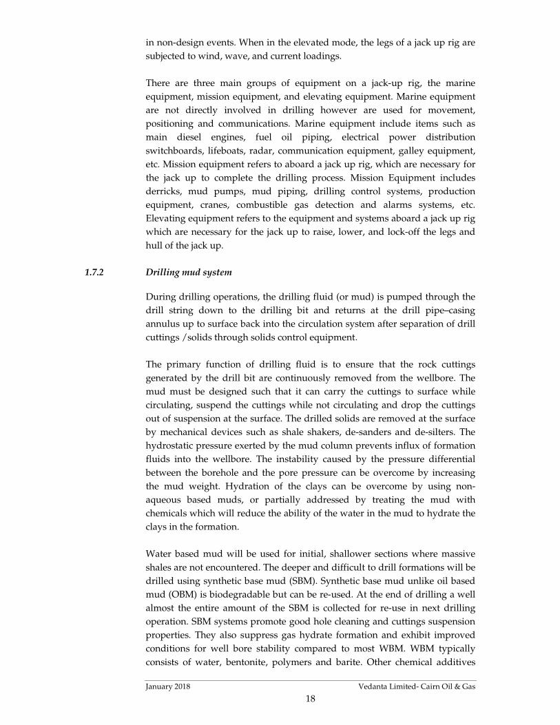
1.7.2 Drilling mud system
During drilling operations, the drilling fluid (or mud) is pumped through the
drill string down to the drilling bit and returns at the drill pipe–casing
annulus up to surface back into the circulation system after separation of drill
cuttings /solids through solids control equipment.
The primary function of drilling fluid is to ensure that the rock cuttings
generated by the drill bit are continuously removed from the wellbore. The
mud must be designed such that it can carry the cuttings to surface while
circulating, suspend the cuttings while not circulating and drop the cuttings
out of suspension at the surface. The drilled solids are removed at the surface
by mechanical devices such as shale shakers, de-sanders and de-silters. The
hydrostatic pressure exerted by the mud column prevents influx of formation
fluids into the wellbore. The instability caused by the pressure differential
between the borehole and the pore pressure can be overcome by increasing
the mud weight. Hydration of the clays can be overcome by using non-
aqueous based muds, or partially addressed by treating the mud with
chemicals which will reduce the ability of the water in the mud to hydrate the
clays in the formation.
Water based mud will be used for initial, shallower sections where massive
shales are not encountered. The deeper and difficult to drill formations will be
drilled using synthetic base mud (SBM). Synthetic base mud unlike oil based
mud (OBM) is biodegradable but can be re-used. At the end of drilling a well
almost the entire amount of the SBM is collected for re-use in next drilling
operation. SBM systems promote good hole cleaning and cuttings suspension
properties. They also suppress gas hydrate formation and exhibit improved
conditions for well bore stability compared to most WBM. WBM typically
consists of water, bentonite, polymers and barite. Other chemical additives

January 2018 Vedanta Limited- Cairn Oil & Gas
19
viz. glycols and salts may be used in conjunction to mitigate potential
problems related to hydrate formation. The mud to be used will be
continuously tested for its density, viscosity, yield point, water loss, pH value
etc. The mud will be prepared onsite (drill location) using centrifugal pumps,
hoppers and treatment tanks. The consumed fraction of the mud, which is
mostly WBM will be discharged into sea intermittently in accordance with
MoEFCC guidelines.
Drill Cuttings Disposal
During drilling activity, cuttings will be generated due to crushing action of
the drill bit. These cuttings will be removed by pumping drilling fluid into the
well via triplex mud pumps. The mud used during such operation will flush
out formation cuttings from the well hole. Cuttings will be then separated
from drilling mud using solids-control equipment. This will comprise a
stepped system of processes consisting of linear motion vibrating screens
called shale shakers, hydro-cyclones (including de-sanders and de-silters), and
centrifuges to mechanically separate cuttings from the mud.
Figure 1.6 A Typical View of Drill Cutting Separation & Treatment System
Offshore Drilling Activity
Drill cuttings will be discharged off-shore into sea intermittently in
accordance with MoEFCC guideline.

January 2018 Vedanta Limited- Cairn Oil & Gas
20
Figure 1.7 Waste Disposal Plan - Offshore
Onshore Drilling Activity
The separated drill cuttings will be disposed in the PCB approved TSDF site
or to the cement industry for co-processing.
Figure 1.8 Waste Disposal Plan - Onshore
Water Consumption
Offshore Drilling Activity
The jack up rig will have a typical storage capacity of 4000 - 5000 bbls (635 -
800 m³) of drill water and 800 - 900 bbls (130 – 145 m³) of water for domestic
and other consumption. The drill water is mainly consumed for preparation of
mud. Minor quantities are used for washing and cleaning the rig. The quantity
of water required for preparation of WBM is around 3000 bbls (478 m³) per
day while for SBM it is 1000 bbls (159 m³) per day. An estimated 20 m³/d of
Or

January 2018 Vedanta Limited- Cairn Oil & Gas
21
fresh water will be used for domestic consumption. Water for Drilling
Activity will be sourced from Port facilities through supply vessels.
Onshore Drilling Activity
Water will be sourced from the CGWB approved ground water sources from
existing Ravva onshore terminal. The approximate water requirement per day
for drilling operations is given in Table 1.6.
Table 1.6 Water Requirement for Onshore Well
Sl. No. Water Requirement Quantity
1 Total water requirement per well including mud
preparation (KL)
2500
2. Drilling water consumption (KLD) 50
3. Water for domestic use 16
Power and Fuel Consumption
Offshore Drilling Activity
DG sets are incorporated in the MODU design / infrastructure for self-
sustained operations at sea. Approximately 4 MW of power generating
capacity will be available at rig using approximately 14 m3/day of High Speed
Diesel. Supply vessels will transport the required fuel from the port.
The power available on the rig will be 8,000 KVA required for offshore drilling
and lighting the quarters at the rig. Power supply shall be made available
through 3 of the 4 main diesel generator sets (each of 2000 kVA) typically
installed on board the jack up rig. There will also be one diesel generators of
500 kVA capacity catering to the emergency auxiliary power supply.
Onshore Drilling Activity
The power requirement in the drilling site and the campsites will be provided
through diesel generator (DG) sets. The rated capacity of the DG sets required
for onshore drilling site is provided in following table.
Table 1.7 Details of DG sets of Onshore Drilling Activity
Location DG Capacity Fuel Requirement
Camp site 2 x 350 kVA (one working and
one standby)
400 liters per day
Drilling site 3 x 1000 kVA (two working
and one standby)
5000 liters per day
The fuel (diesel) will be received in bulk quantity through tankers and shall be
stored in above ground steel diesel tanks (between 30 to 60 m3 capacity). The

January 2018 Vedanta Limited- Cairn Oil & Gas
22
tank area is generally of 14 m x 13m and is provided with secondary
containment of adequate capacity to control any accidental leaks.
Sanitation
Offshore Drilling Activity
There will be an On-board Sewage Treatment Plant to meet the requirements
of the MARPOL Convention and the treated sewage will be discharged to sea.
The on-board STP will typically consist of solids / oil separation and chemical
oxidation to remove the organic load. The food wastes will be macerated
through a grinder and disposed offshore.
During drilling for 45 to 90 days per well, it is expected that approximately 20-
25 kg per day of kitchen wastes from offshore rig. The food residual generated
on board will be ground to pass through 25-mm mesh screen. The comminute
food waste will be discharged offshore as per MARPOL Convention.
Onshore Drilling Activity
Each drill site and camp site will have modular ETP for treatment of domestic
waste water generated from the drill sites. The treated water will be disposed
as per CPCB discharge standard.
Manpower
It is estimated that about 80-120 workers will be required at each drill site
which will comprise of engineers, skilled workers and support staff.
1.8 WASTES & EMISSIONS
Offshore Drilling Activity
The source of air emissions anticipated from offshore drilling are those
resulting from combustion of fuel in Diesel Generator sets on the offshore rigs,
exhaust emissions from supply vessels and due to helicopter movements.
Vedanta Ltd (Cairn Oil and Gas) proposes to use low sulphur HSD as fuel to
the DG sets. The power generation capacity required is around 4 MW and the
maximum fuel consumption will be around 14 m3. The operational period at a
single well will be around 25 – 30 days. The DG sets will be equipped with
stack suitable for a marine vessel operation and designed to international
norms and in compliance to common industry practice. The engines will also
be subjected to periodic maintenance to ensure efficient combustion and
minimize emission of particulate matter and exhaust gases. The emissions
from each of the diesel generators will be limited to the following levels:
� Particulate matter: < 75 mg/Nm3,
� SO2 : < 100 mg/Nm3
� NOx : < 1320 mg/Nm3

January 2018 Vedanta Limited- Cairn Oil & Gas
23
� CO : <150 mg/Nm3
� HC : <100 mg/Nm3
Other emission would be from temporary test flaring for 2 to 3 days for the 6
number of exploratory/appraisal wells, in the event of discovery of
hydrocarbons from the new prospect structure. In such event, the expected
emissions during flaring would be:
� PM : < 50 mg/Nm3
� SO2 : Nil (the field being sweet in nature)
� NOx : < 145 mg/Nm3
� HC : < 130 mg/Nm3
� CO : < 350 mg/Nm3
There will also be emissions due to combustion of marine gas oil in engines of
5 to 6 support vessels engaged for providing support services for rig
operations as well as for maintaining safety in the exclusive zones of 500 m
from the drilling locations.
The expected waste generation from well drilling will be as per Table 1.8.
Table 1.8 Waste Generation from Well Drilling
S.N. Nature of waste Quantity during
Drilling Activities
A Hazardous Waste
1 Drill cuttings containing oil 250 m3 per well
2 Residual drilling mud, sludge and other drilling
waste
200 m3per well
3 Used Lubricating oil 10 m3per well
B Non Hazardous Waste
4 Food waste 25 kg per day
5 Non-combustible waste containing metallic
residues, glass
20 kg per day
6 Packaging wastes including drums, wooden pallets,
plastic containers, plastic foils.
1000 kg per well
7 Left over chemicals and materials, scrap metal,
sludges, scales, batteries, spent acids, spent
lubricants, filters etc.
250 kg per well
8 Cement, grit, blasting and painting wastes. 500 kg per well
Disposal of wastes will be as per prior approval of APPCB.
Waste drill cutting washing fluid will be collected in a gravity tank of 10 m3
capacity provided with agitation system. The Tank is provided with oil
recovery system by pumping out oil. The wash water will be recirculated
within the mud.

January 2018 Vedanta Limited- Cairn Oil & Gas
24
From Offshore Drilling Rig
During the operation of the offshore drilling rig, few liquid waste streams /
products are generated. These wastes are stored, handled and disposed as per
the requirements of MARPOL convention and in compliance to the applicable
Indian regulation. The major liquid, solid waste discharges anticipated due to
drilling operations include spent drilling mud and drill cuttings. All the major
waste streams from drilling operations grouped under different categories.
Domestic wastewater from kitchen, shower, toilets and laundry area on board
drilling rig will be approximately 30 m3/day. Domestic wastewater will be
treated in on board Sewage treatment plant (STP) for physico–chemical and
biological treatment through extended aeration system before offshore
discharge of treated sewage complying with MARPOL convention. Bilge
water consisting of rainwater/seawater containing diesel and oil will be
10m3/well. Bilge water will be collected into a sludge tank and then to a
water/oil separator on board drilling rig before offshore disposal with less
than 15 mg/l of oil and grease content.
For the proposed development production, exploratory/appraisal drilling a
maximum of 85 m3/day of water will be used in the drilling rig, out of which
45 m3/day is fresh water and 40 m3/day of seawater for both drilling and
domestic use. Fresh water will be supplied by sea and stored onboard the rig.
The balance water requirement will be met through seawater, which will be
lifted from the rig location. Part of the fresh water is also made on board rig
using water makers on the rig.
The quantity of water required for preparation of WBM is around 478 m3 per
day, while SBM is 159 m3 per day. Water will be taken through supply vessels
for drilling operation. Being in the deltaic region, water availability is
considered adequate in the region.
For offshore drilling, fresh water will be sourced from commercial suppliers
near the Port of entry. Sea water will be lifted from the sea near the rig
location. Water requirement of the onshore wells will be met through bore
wells located within the onshore Ravva Terminal.
1.9 CHANGES IN PRODUCTION PROFILE AND ADEQUACY ASSESSMENT OF EXISTING
INFRASTRUCTURE
Implementation of the proposed project will result in incremental changes in
current production profiles, however the production capacities will remain
within the already approved capacities of 50,000 BOPD of crude oil and 2.32
MMSCMD of gas. No additional requirement power, water and fuel
requirement and volume of wastes will be generated than the approved
capacities of the Ravva Field. Table 1.9 provides an indication on the changes
anticipated and adequacy assessment of existing infrastructure.

January 2018 Vedanta Limited (Cairn Oil & Gas)
25
Table 1.9 Adequacy Analysis of the Ravva Field vis-à-vis proposed Ravva Development Program
S.N. Parameter Units Installed
Capacity
Approved
Capacity
Present Avg.
Production
Expected Capacity
post Proposed
Development
Remarks
1 Plant fluid
handling
capacity
Barrels of Fluid
per day
90,000 90,000 70,000 90,000 Total fluid handling capacity of
the plant is the primary
determining factor for crude, gas
and produced water production.
The total fluid handling capacity
is adequate to cater for changes in
production profile due to the
proposed development.
Due to aging of the field it is
anticipated that the existing
production levels will drop and
incremental increase will suffice
the production to present levels.
2 Crude
production
Barrels of Oil
per day
As per fluid
characteristics
50,000 15,000 35,000
3 Associated and
non- associated
gas production
MMSCFD As per fluid
characteristics
81.96
(2.32 MM-
SCMD)
51.0 65.5
4 Produced water
generation
Barrels of water
per day
As per fluid characteristics 55,000 55,000
5 Power
generation
MW 10 10 5 5 No change anticipated
6 Fuel
consumption
(natural gas)
MMSCFD 4.0 Not described 4.0 4.0 No change anticipated

January 2018 Vedanta Limited (Cairn Oil & Gas)
26
S.N. Parameter Units Installed
Capacity
Approved
Capacity
Present Avg.
Production
Expected Capacity
post Proposed
Development
Remarks
7 Water
consumption
(bore wells)
m3/day 6 bore wells 10,413 9,500 18,285 Additional requirement of ~7872
m3/day ground water extraction
is anticipated. Permission for
extraction of additional 7872
m3/day ground water will be
obtained from Ground Water
Authority.
8 Borewell Water
for Injection
m3/day Not described Not described 9,170 0 17,042 Additional requirement of 7872
m3/day is anticipated.
9 Domestic
consumption
m3/day 140.0 Not described 140.0 140.0 No change anticipated
10 Produced water
re-injection
Barrels of water
per day
90,000 90,000 36,000 50,000 No change in approved capacity
anticipated
11 Effluent
generation &
treatment
m3/day 3,000 3,000 1563 3000 No change in approved capacity
anticipated
Note: MMSCFD = million standard cubic feet per day; 1 standard cubic feet = 0.028317 standard cubic meter; MMSCMD = million standard cubic meter
per day

January 2018 Vedanta Limited- Cairn Oil & Gas
27
2 SITE ANALYSIS
The description of the project block and its location is given in Section 1. An
existing onshore Ravva Terminal is located ~1 km from shoreline and
approximately 6 to 13 km from nearest RH Platform to farthest platform RI
platform from the Ravva Terminal.
2.1 CONNECTIVITY
The Ravva onshore terminal is located in village Surasaniyanam in East
Godavari District.
2.1.1 By Road
It is connected by road with the nearest town being Amalapuram at ~13 km
distance.
2.1.2 By Rail
The nearest railway stations are Palakollu and Narasapur at distances of 45
km and 48 km respectively.
2.1.3 By Air
The nearest airport is Rajahmundry located at ~90 km from Ravva Terminal.
Other nearest airport is at Vishakhapatnam (VIZAG) located at ~200 km from
Ravva Terminal.
2.1.4 By Sea
The nearest port that can be used by marine vessels is the Kakinada Port.
There are though minor fishing ports much nearer than Kakinada.
2.1.5 From Ravva Terminal
The offshore areas of the block can be accessed by boats / marine vessels and
helicopter. There is a helipad at Ravva Terminal from where there are sorties
almost every day to the platforms. All the platforms have helicopter landing
and boat landing facilities.
2.2 LAND FORM, LAND USE AND LAND OWNERSHIP
The proposed developments are mostly planned in offshore and partly in on-
shore. The offshore areas in the field are used for commercial fishing. There is
however an exclusion zone of 500 m radius around all offshore installations
i.e. platforms and SPM where fishing is not allowed.

January 2018 Vedanta Limited- Cairn Oil & Gas
28
The proposed onshore well pads (eight numbers) are located the backwater
region. Amongst them two well pads have already been developed previously
by Cairn as part of earlier exploratory drilling activity. The remaining six well
pad sites are located the backwater region having no vegetation; tidal
influence was observed during site visit.
2.3 TOPOGRAPHY
The coastline along the PKGM-1 block is dominated by the large delta of
Godavari River with prominent geomorphic features comprising ancient
channels (abandoned streams), flood plain terraces, river mouth bars, lagoons,
ancient beach ridges, old tidal flats, mud flats, mangrove swamps and spits.
The PKGM-1 area lies offshore from the Godavari Delta. The Godavari River
drains an area of 286,720 sq. km, flowing 1,440 km in an east-south-easterly
direction. Its delta of 4,163 sq. km extends 35 km out into the Bay of Bengal
and has a 150 km long coast. The apex of the delta is just to the south of the
town of Rajahmundry.
The sea floor of the Bay of Bengal shows a broad U shaped basin open at its
southern end. The continental shelf adjacent to the Godavari River delta is
narrow, with the continental slope starting at the 90-m depth contour. Water
depths across the PKGM-1 block shelve very gently away from the coast with
the 10 m depth contour lying 3-4 km from the shore to more than 30 m.
2.4 CLIMATE
The climate of the region is tropical, maritime and seasonal in character. Air
temperature and humidity are high throughout the year. Pressure gradients
are weak. The climate is greatly influenced by the southwest and northeast
monsoons. The pre monsoon (April to May) and post monsoon seasons
(October to November) are the transition periods and are characterized by
occurrence of cyclonic storms having active storms during the latter periods.
The Southwest monsoon is characterized by strong and persistent wind and
rough sea conditions. Northeast monsoon is characterized as fair weather
season with light, variable winds and usually calms sea conditions.
The annual atmospheric temperature distribution shows significant seasonal
and temporal variations. The highest temperature of 42.5OC occurred in the
month of May. The lowest temperature of 16.4OC occurred in the month of
December. The variations in pressure are very small and are in the order of 3-5
mb, with the lowest of 998 mb in the month of July and the highest of 1017 mb
in the months of January. The average relative humidity values varied from
the lowest of 62% in the month of May to the highest of 85% in the month of
August. The humidity is relatively higher in the morning hours than the
evening hours. The rainfall in the region is mainly during the two-monsoon
period’s i.e. south-west monsoon (May to September) and the north-west

January 2018 Vedanta Limited- Cairn Oil & Gas
29
monsoon (December to February). The annual rainfall in the area is about
1165.9 mm with considerable variations from year to year. More than 90% of
the rainfall is recorded during the months of June to November. Occasional
rains are also observed in the non-monsoon months.
2.5 ECOLOGICAL SENSITIVITY
Wildlife Sanctuary
Coringa Wildlife Sanctuary is located at more than 18 km from the PKGM-1
Block.
Water Courses & Estuary Area
� Estuary of Vrudha Gautami (Gautami Godavari) River, a distributary of
the Godavari River is located at ~4 km northeast of the Block boundary.
� Nilarevu, a distributary of Varudha Gautami Godavari, is located at about
16 km northeast of the block.
� Vainateyam Godavari River located at ~12 km from the Block boundary to
the southwest of the block.
CRZ:
The proposed onshore and offshore wells are located in the CRZ zone.
Forests
Forests within Mummidivaram Taluka include the following:
� Masonithippa RF
� Baulsuthippa RF
� Moori RF
� Rathukalva RF
� Kandikuppa RF
� Mattithippa RF
� Kothapalem extension RF
� Bairavapalem RF
Turtle Nesting Site
� Sacramento Sole is located 2.4 km from Block boundary; however, all the
proposed wells are located more than 10 km from the Sole.
� Hope Island is located at more than 41 km from Block boundary.

January 2018 Vedanta Limited- Cairn Oil & Gas
30
2.6 SOCIAL INFRASTRUCTURE
The area surrounding the Ravva Terminal has basic infrastructure facilities in
terms of roads, electricity, drinking water and transportation.

January 2018 Vedanta Limited (Cairn Oil & Gas)
31
3 PLANNING BRIEF
3.1 PLANNING CONCEPT
The project is an oil and gas development spread over in PKGM-1 Block of
area 331.26 km2 already under exploration and operation since 1988. The
approved crude oil production from the Ravva Field is 50,000 BOPD and 2.32
MMSCMD of gas. From the Ravva Terminal, the crude oil is dispatched to
Single Point Mooring facility available at approximately 15 km in the offshore
region from the terminal from where it is offloaded to marine tankers for
further processing in the nearby refinery. The gas from the Ravva Terminal is
dispatched through gas metering system into the GAIL pipeline. The
proposed development will help further augment the declining production
levels from the Ravva Field. Due to the proposed project development, no
significant additional population is anticipated and no significant additional
infrastructure demand and amenities/ facilities are anticipated.

January 2018 Vedanta Limited (Cairn Oil & Gas)
32
4 PROJECT SCHEDULE & COST ESTIMATES
4.1 PROJECT SCHEDULE
Vedanta Ltd (Cairn Oil & Gas) has planned to develop the available
hydrocarbon resources from the PKGM-1 Block in next 10 years.
4.2 ESTIMATED PROJECT COST
The cost of the project is estimated to be ~ INR 7,924 Crores.

January 2018 Vedanta Limited (Cairn Oil & Gas)
33
5 ANALYSIS OF PROPOSALS
5.1 FINANCIAL BENEFITS
Following financial benefits are expected from the proposed development
program:
� Majority of the infrastructure for processing of production/well fluid are
already available through the operating Ravva on-shore Terminal.
� The increase in production of oil and gas within the already approved
capacity will add to the energy independence of the nation and will reduce
the import bills. Please note that in-spite of the incremental increase in
production the total production will be within the approved quantity;
� Based on the comparative cost benefit analysis, the project is found to be
economically viable.
5.2 SOCIAL BENEFITS
Following social benefits are expected:
� No interference with the local community as the proposed project involves
development drilling in the offshore region sufficiently away from the
coast;
� No interference with the fishing community since the project site is within
the boundary limits of PSC block;
� Cairn is already taking up of corporate social responsibility (CSR) actions
in the region which will be continued to be taken up as described in the
following section.
5.3 CSR ACTIVITIES
Ravva, one of Cairn’s active assets is located in Surasaniyanam Village (also
known as S’Yanam). The Ravva JV onshore terminal operated by Cairn is the
first and only tryst with industrialization for this remote village. Keeping this
unique scenario in mind, Ravva JV for the past many years has initiated
several CSR programmes aimed at improving infrastructure, economic
development, health and educational facilities. The Ravva JV has also
accelerated growth of micro enterprises through vendor development
programme.
The implementation of the projects are carried out through partnership with
the State Government’s District Administration, community-based
organizations, like minded corporate, NGOs (national as well as local) and
specialized knowledge partners like NASSCOM Foundation, NIIT etc.

January 2018 Vedanta Limited (Cairn Oil & Gas)
34
There is a two pronged strategy for CSR that is based on the principles of
inclusive growth and holistic development of the area. Two pathways of CSR
implementation are given as under:
Financial Support to District administration for Infrastructure development
programs at Uppalaguptam and Amalapuram Mandals:
Since the year 2000, Ravva JV has been funding to the development fund
maintained with the District Collector with an understanding that 50% of the
funds will be used for S.Yanam Village, 20% of the funds will be used for en-
route villages from Amalapuram to S.Yanam, 20% of the funds will be utilized
for Uppalaguptam Mandal and 10% of funds will be used for maintenance of
old structures etc. Numerous infrastructure development works like
construction of roads, bus shelters, water supply tanks & pipelines, individual
toilets etc. were undertaken in S’Yanam as well as neighbouring villages
through these funds.
Direct Implementation of Programs at S’Yanam Village focused on Health,
Education and Economic empowerment:
Education: The most intensive CSR activities are conducted at this level. The
major emphasis is on addressing the issue of unemployment by providing
skills to the village youths and making them employable according to their
qualifications and interests. Multiple options are given to the youths for career
choices for a more inclusive decision making. For a long term sustainable
development we have designed programs for the younger generation of the
village through various educational projects tailor made for all levels starting
from preschool to post graduate.
Economic Empowerment: On this front, the Company is providing monthly
pensions to physically handicapped persons and widows in S’Yanam Village.
Also as a part of empowerment strategy Cairn is promoting Micro-Vendor
Programme since the year 2004-05. The ideology of the Company is to include
the villagers in the growth trajectory by providing them adequate
opportunities, building their capacities and develop entrepreneurship
qualities among them. Several contracts for support services like civil works,
Painting works, Green belt development, vehicles etc. were given to the
villagers. The aims of these initiatives were to provide more opportunity for
vendors on the doorstep of Cairn India’s Production activity. In addition to
this Cairn is also promoting micro enterprise development for the women
folks in the village leading to better quality of life and a larger participation of
them in family decisions.
Health: The Ravva JV is maintaining a Health clinic in the village, and
provides free medicines. Cairns has also sponsored construction of a hospital
building in the village and has got approval from the government to initiate a
Primary Health Centre in the village. The Company also supports the Village

January 2018 Vedanta Limited (Cairn Oil & Gas)
35
Panchayat to carryout quarterly fumigation to avoid the spread of mosquitoes
and other vector borne diseases.
*****************