Embed Size (px)
Citation preview
LINEARSWING GATEOPERATORS
TM
VECTOR2 Installation Manual
Company Profile
CENTURION SYSTEMS (Pty) Ltd reserves the right to make changes to the products described in this manual without notice and without obligation of CENTURION SYSTEMS (Pty) Ltd to notify any persons of any such revisions or changes. Additionally, CENTURION SYSTEMS (Pty) Ltd makes no representations or warranties with respect to this manual.
No part of this document may be copied, stored in a retrieval system or transmitted in any form or by any means electronic, mechanical, optical or photographic, without the express prior written consent of CENTURION SYSTEMS (Pty) Ltd.
Sales and technical support to over 50 countries
worldwide
1986 1990 1995 1999Centurion Systems
Today
100% testing of products
In-houseR & Ddevelopmentteam
Manufacture tointernational
quality standardISO 9001:2008
After-sales
technical supportfrom 07h00 - 18h00
Monday to Friday

Contents
page 1 page 2 page 2
page 3
Mechanical Setup Electrical Setup Commissioning and Handover
IMPORTANT SAFETY INSTRUCTIONS
1. Declaration of Conformity page 5
2. General Description page 6
Lightning Protection page 7
3. Icons Used in this Manual page 7
4. Specifications page 8
Physical Dimensions page 8 Technical Specifications page 9 Control Card page 10 Power Supply page 10 Power Supply, Control Box and Control Card Assembly 2 page 10 Allowable Gate Mass page 11
5. Product Identification page 12
6. Required Tools and Equipment page 14
7. Preparation of Site page 15
General Considerations for the Installation page 15 Strength of the Pillar page 16 Strength of the Gate and Gate Bracket page 19 Mechano Kit Installation Options page 20 High-Security Kit Installation Options page 21
8. Cabling Requirements page 22
9. Critical Installation Checklist page 23
10. Operator Installation page 24
Determine the Gate Bracket Position page 25 Fasten Gate Bracket to Gate page 27 Adjust Origin Clamp page 28 Inward Swing Gate Setup page 29 Outward Swing Gate Setup page 32
11. Determine Gate Swing Angle page 35
12. Allowable Wind Load page 36

13. Electrical Setup page 37
Secure Control Box to Wall page 37 Connecting all Wiring page 37 Setting the Limits page 38
14. Wiring Diagram for Closing Safety Beams page 40
15. Wiring Diagram for Opening Safety Beams page 41
16. Wiring Diagram for External Radio Receiver and Loop Detector page 42
17. Wiring Diagram for Other Inputs page 43
18. Wiring Diagram for Master Motor (MTRM) page 44
19. Wiring Diagram for Slave Motor (MTRS) page 45
20. Charger and Pillar Light Connections page 46
21. Solar Panel Wiring page 47
22. Setting up Additional Features page 48
23. Menu Navigation Map page 48
24. Controller Features page 52
25. Factory Defaults Schedule page 63
26. Description of Terminal Functions page 69
27. Diagnostics page 72
Diagnostic LEDs page 72 Gate Status LED Indication page 72 LCD Display page 73 Buzzer Feedback page 74
28. Installation Handover page 75

Mount controller enclosure and connect all wiring
Check cabling requirements
Mechanical Setup
Gather required tools and equipment Page 14
Heed necessary site considerations Page 15
Page 22
Mount the wall bracket Page 25
Install motor and link to gate Page 25
Page 37
These quick steps are for the experienced installer who needs a checklist to get a standard installation up and running in the minimum of time.
Detailed installation features and functions are referred to later in this manual.
Page 1
Fit mechanical endstops Page 38

Electrical Setup
Page 2
Commission system
Commissioning and Handover
Carry out professional handover to client
Page 62
Page 74
Connect all wiringRun setup routine Page 408
10

Warnings for the installerCAREFULLY READ AND FOLLOW ALL INSTRUCTIONS before beginning to install the product.
All installation, repair, and service work to this product must be carried out by a suitably qualified person
This appliance is not intended for use by persons (including children) with reduced physical, sensory or mental capabilities, or lack of experience and knowledge, unless they have been given supervision or instruction concerning use of the appliance by a person responsible for their safety
Do not activate your gate unless you can see it and can determine that its area of travel is clear of people, pets, or other obstructions
NO ONE MAY CROSS THE PATH OF A MOVING GATE. Always keep people and objects away from the gate and its area of travel
NEVER LET CHILDREN OPERATE OR PLAY WITH THE GATE CONTROLS
Secure all easily-accessed gate opener controls in order to prevent unauthorised use of the gate
Do not in any way modify the components of the automated system
Do not install the equipment in an explosive atmosphere: the presence of flammable gasses or fumes is a serious danger to safety
Before attempting any work on the system, cut electrical power to the operator and disconnect the batteries
The mains power supply of the automated system must be fitted with an all-pole switch with contact opening distance of 3mm or greater. Use of a 5A thermal breaker with all-pole circuit break is recommended
IMPORTANTSafety Instructions
ATTENTIONTo ensure the safety of people, it is important that you read all the following instructions. Incorrect installation or incorrect use of the product could cause serious harm to people.
The installer, being either professional or DIY, is the last person on the site who can ensure that the operator is safely installed, and that the whole system can be operated safely.
Page 3

Make sure that an earth leakage circuit breaker with a threshold of 30mA is fitted upstream of the system
Never short-circuit the battery and do not try to recharge the batteries with power supply units other than that supplied with the product, or by CENTURION
Make sure that the earthing system is correctly constructed, and that all metal parts of the system are suitably earthed
Safety devices must be fitted to the installation to guard against mechanical movement risks such as crushing, dragging and shearing
It is recommended that at least one warning indicator light be fitted to every system
Always fit the warning signs visibly to the inside and outside of the gate
The installer must explain and demonstrate the manual operation of the gate in case of an emergency, and must hand the User Guide/Warnings over to the user
Explain these safety instructions to all persons authorised to use this gate, and be sure that they understand the hazards associated with automated gates
Do not leave packing materials (plastic, polystyrene, etc.) within reach of children as such materials are potential sources of danger
Dispose of all waste products like packaging materials, worn- out batteries, etc., according to local regulations
Always check the obstruction detection system, and safety devices for correct operation
CENTURION does not accept any liability caused by improper use of the product, or for use other than that for which the automated system was intended
This product was designed and built strictly for the use indicated in this documentation. Any other use, not expressly indicated here, could compromise the service life/operation of the product and/or be a source of danger
Everything not expressly specified in these instructions is not permitted
Page 4

Page 5
1. Declaration of Conformity
Manufacturer
Centurion Systems (Pty) Ltd
Unit 13 Production Park
Intersection of Newmarket Road and Epsom Avenue
North Riding
Gauteng
South Africa
Declares that the product
Product name: VECTOR2 Swing gate operator
Product options: All variants
Conforms with the following specifications
Safety: SANS 60335-1:2007
IEC 60335-1:2006
Emissions: CISPR 22 CLASS B: Radiated emissions – 30MHz to 1000MHz
CISPR 22 CLASS B: Conducted emissions – 150 KHz to 30MHz
Immunity: IEC 61000-4-2 – Electrostatic discharge
IEC 61000-4-3 – Radiated immunity – 80MHz to 1000MHz
IEC 61000-4-4 – Electrical fast transients/burst
IEC 61000-4-5 – Surge immunity test
IEC 61000-4-6 – Conducted immunity – 150KHz to 80MHz
IEC 61000-4-8 – Power frequency magnetic field
IEC 61000-4-11– Voltage dips and interruption
Standard to which conformity is declared
IEC 60335-1:2006 Safety
IEC 61000-6-3 Emissions
IEC 61000-6-1 Immunity
Signed at North Riding, South Africa on June 21, 2010
Ian Rozowsky
Research & Development Director
2. General Description
Page 6
The VECTOR2 operator has been designed to safely and cost-effectively automate a wide variety of swing gates, from single light-domestic swing gates to heavy industrial double swing gates.
The fail-safe and fully redundant Position and Collision Detection system has been designed and tested to set the standard in safety of operation and to provide an unparalleled level of reliability and durability in operation.
The gate Travel Limits are managed by a sealed double-redundant opto-electronic system that has been designed not only to ensure ultra-reliable operation, but also to ensure precise position and trajectory control. This enables very accurate and reliable collision detection to ensure safe operation even under trying conditions.
The VECTOR2 control card has been designed to be easy and intuitive to use, with helpful instructions on the status of the operation being given both during and after the installation. It also has a built-in diagnostic procedure that can verify every aspect of the control card onsite.
Some of the advanced features offered by the VECTOR2 controller are:
Fully automated single-button Limit Setup for single and double swing gates Full graphics LCD display provides an intuitive user interface with built-in diagnostics to
speed up and simplify the installation process Separate safety inputs for infrared beams on both the closing and opening directions of
the gate Advanced closed-loop speed control to maintain safe and reliable operation on inclined
gates under windy conditions Fully configurable gate Run Profiles Selectable and adjustable Autoclose with pushbutton override Pedestrian (Partial) opening with automatic closure Free-exit input Positive Close Mode Multiple Modes of Operation Solenoid lock drive output up to 2A Holiday Lockout A status LED output to indicate the gate status remotely Pillar Light control Leaf delay is selectable for either gate leaf Onboard CENTURION receiver with selective adding and deleting of remotes
Page 7
Lightning Protection
The VECTOR2 electronic controller utilises the same proven surge protection philosophy that is used in all CENTURION products. While this does not guarantee that the unit will not be damaged in the event of a lightning strike or power surge, it greatly reduces the likelihood of such damage occurring. The earth return for the surge protection is provided via the mains power supply earth. In order to ensure that the surge protection is effective, it is essential that the unit is properly earthed.
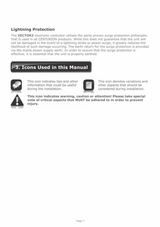
3. Icons Used in this Manual
This icon indicates tips and other information that could be useful during the installation.
This icon indicates warning, caution or attention! Please take special note of critical aspects that MUST be adhered to in order to prevent injury.
This icon denotes variations and other aspects that should be considered during installation.
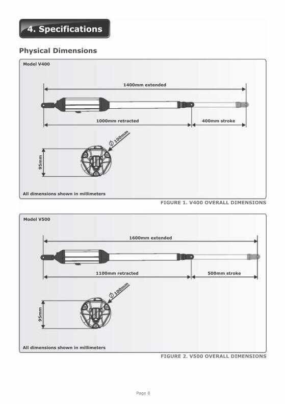
4. Specifications
FIGURE 2. V500 OVERALL DIMENSIONS
All dimensions shown in millimeters
FIGURE 1. V400 OVERALL DIMENSIONS
Page 8
All dimensions shown in millimeters
Physical Dimensions
1400mm extended
1000mm retracted 400mm stroke400mm stroke400mm stroke
Model V400
100mm
95
mm
Model V500
1600mm extended
1100mm retracted 500mm stroke
95
mm
100mm

Page 9
VECTOR2 400 VECTOR2 500
Input voltage
Motor voltage
Motor power supply
Battery charger
Domestic
Light-industrial
Current consumption (mains)
Current consumption (motor at rated load)
Operator push force - maximum
Operator stroke
Piston extension/retraction speed
Typical gate opening time
Manual override
Maximum number of operations per day
Duty cycle - mains present
Operations in standby with 7Ah battery
Half day
Full day
Collision sensing
Controller solenoid output rating
Operating temperature range
Onboard receiver type
Receiver code storage capacity
Receiver frequency
Mass of unit packed (excluding battery)
Single kit
Double kit
Degree of protection
90V / 220V - 240V AC ± 10%, 50Hz
12V DC
Battery-driven (standard capacity - 7Ah)
CP84E - 800mA @ 13.8V
CP84SM - 2A @13.8V
60mA / 170mA
15A - maximum
250kgf
27mm/sec
Key release
100 /250
25% /50%
70
58
Electronic
2A DC
-15°C to +50°C
CENTURION code-hopping multichannel
64 transmitter buttons
433MHz
IP54
400mm 500mm
<14 sec <17 sec
8.5kg
14kg
9kg
15kg
Technical Specifications
Applies to CP84SM light-industrial unit only
Can increase battery capacity for longer standby times
Can operate off a solar supply, consult Centurion Systems (Pty) Ltd for assistance
Domestic
Light-industrial
Assumes full stroke of operator is used
Based on 25°C ambient temperature and unit not in direct sunlight
Based on an operator push force of less than 50% of rated
Based on double kit excluding Infrared Safety Beams
Assumes a 90° opening gate and optimum mounting position
Page 10
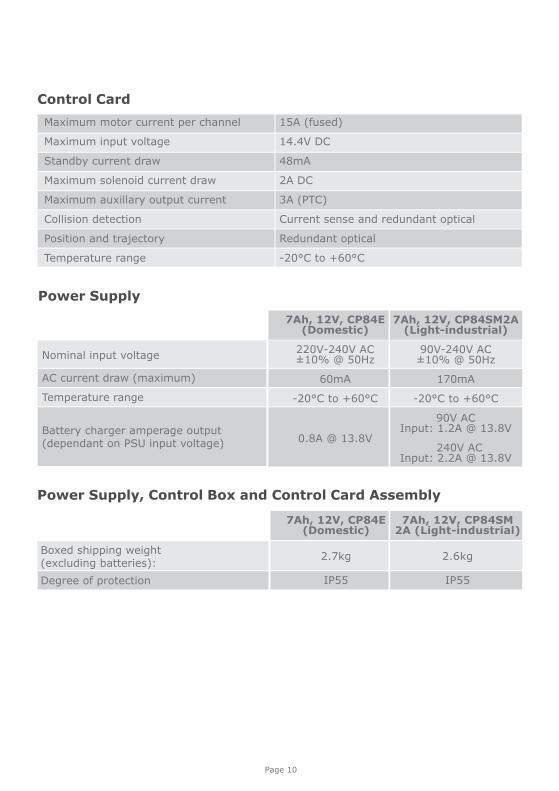
Control Card
Power Supply
Maximum motor current per channel 15A (fused)
Maximum input voltage 14.4V DC
Standby current draw 48mA
Maximum solenoid current draw 2A DC
Maximum auxillary output current 3A (PTC)
Collision detection Current sense and redundant optical
Position and trajectory Redundant optical
Temperature range -20°C to +60°C
Nominal input voltage
AC current draw (maximum)
Temperature range
Battery charger amperage output (dependant on PSU input voltage)
7Ah, 12V, CP84E(Domestic)
220V-240V AC ±10% @ 50Hz
60mA
-20°C to +60°C
0.8A @ 13.8V
7Ah, 12V, CP84SM2A (Light-industrial)
90V-240V AC ±10% @ 50Hz
170mA
-20°C to +60°C
90V AC Input: 1.2A @ 13.8V
240V AC Input: 2.2A @ 13.8V
Boxed shipping weight (excluding batteries):
Degree of protection
7Ah, 12V, CP84E (Domestic)
2.7kg
IP55
7Ah, 12V, CP84SM 2A (Light-industrial)
2.6kg
IP55
Power Supply, Control Box and Control Card Assembly
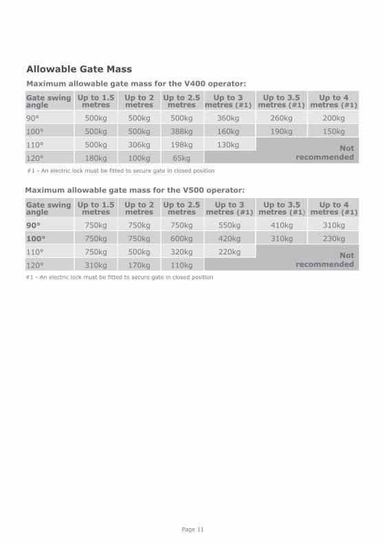
Maximum allowable gate mass for the V500 operator:
#1 - An electric lock must be fitted to secure gate in closed position
Page 11
Allowable Gate Mass
Gate swing angle
90°
100°
110°
120°
Gate swing angle
90°
100°
110°
120°
Up to 1.5 metres
500kg
500kg
500kg
180kg
Up to 1.5 metres
750kg
750kg
750kg
310kg
Up to 2 metres
500kg
500kg
306kg
100kg
Up to 2 metres
750kg
750kg
500kg
170kg
Up to 2.5 metres
500kg
388kg
198kg
65kg
Up to 2.5 metres
750kg
600kg
320kg
110kg
Up to 3 metres (#1)
360kg
160kg
130kg
Up to 3 metres (#1)
550kg
420kg
220kg
Up to 3.5 metres (#1)
260kg
190kg
Up to 3.5 metres (#1)
410kg
310kg
Maximum allowable gate mass for the V400 operator:
#1 - An electric lock must be fitted to secure gate in closed position
Not recommended
Not recommended
Up to 4 metres (#1)
200kg
150kg
Up to 4 metres (#1)
310kg
230kg
1
5
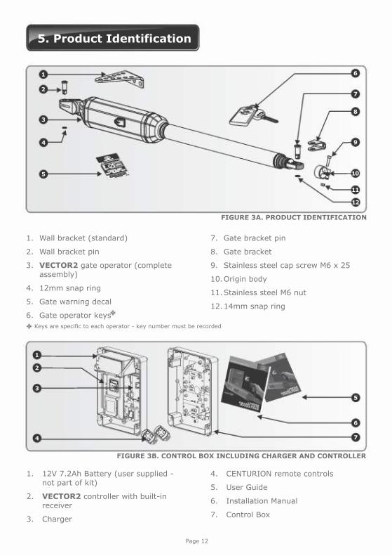
Keys are specific to each operator - key number must be recorded
1. Wall bracket (standard)
2. Wall bracket pin
3. VECTOR2 gate operator (complete assembly)
4. 12mm snap ring
5. Gate warning decal
6. Gate operator keys
7. Gate bracket pin
8. Gate bracket
9. Stainless steel cap screw M6 x 25
10. Origin body
11. Stainless steel M6 nut
12. 14mm snap ring
5. Product Identification
1. 12V 7.2Ah Battery (user supplied - not part of kit)
2. VECTOR2 controller with built-in receiver
3. Charger
3
4
2
9
12
7
6
8
10
11
2
3
6
1
5
7
Page 12
FIGURE 3A. PRODUCT IDENTIFICATION
FIGURE 3B. CONTROL BOX INCLUDING CHARGER AND CONTROLLER
4
4. CENTURION remote controls
5. User Guide
6. Installation Manual
7. Control Box
Page 13
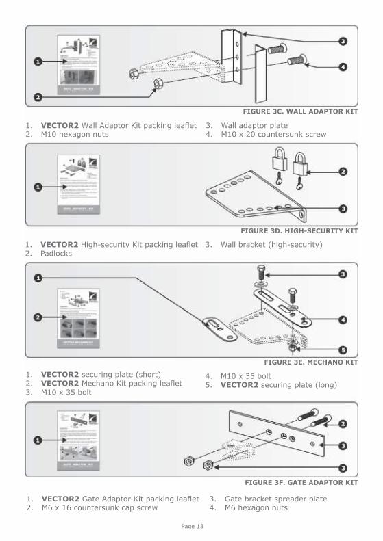
1. VECTOR2 Wall Adaptor Kit packing leaflet2. M10 hexagon nuts
3. Wall adaptor plate4. M10 x 20 countersunk screw
FIGURE 3C. WALL ADAPTOR KIT
3
4
2
1
1. VECTOR2 High-security Kit packing leaflet2. Padlocks
3. Wall bracket (high-security)
1. VECTOR2 securing plate (short)2. VECTOR2 Mechano Kit packing leaflet3. M10 x 35 bolt
4. M10 x 35 bolt5. VECTOR2 securing plate (long)
1. VECTOR2 Gate Adaptor Kit packing leaflet2. M6 x 16 countersunk cap screw
3. Gate bracket spreader plate4. M6 hexagon nuts
FIGURE 3D. HIGH-SECURITY KIT
FIGURE 3E. MECHANO KIT
FIGURE 3F. GATE ADAPTOR KIT

Spanners 17mm15mm
preferably socket set
Crimping tool and
Pin lugs
Masonry bits12mm
10mm for wall mount brackets6.5mm/10.5mm steel bits
G-clamps x 2
Measuringtape
Welding machine(including consumables and safety equipment)
Hacksaw
Allen key5mm
Spirit level
Extension cord
Marking pen/chalk
Safety equipment(goggles, gloves etc.)
Pin punch6mmAngle grinder
Hammer
Pliers
Hole saw20mm
Connectorblock
Electric drilling
machine
Screwdrivers6mm Phillips3.5mm Flat
Soldering iron
Page 14
6. Required Tools and Equipment
FIGURE 4
7. Preparation of Site
General Considerations for the Installation
Always recommend the fitment of additional safety equipment such as safety edges and Safety Beams, for additional protection against entrapment or other mechanical risks
Check that no pipes or electrical cables are in the way of the intended installation Check that enough space is available for the gate operator with the gate in the
required open position (see Figures 4 and 5) Check the strength of the mounting pillar and fit a Wall Adaptor Kit where needed If the swing gate leaf is longer than 2.5 metres, ensure that a lock can be fitted Never fit the operator on the outside of the gate, where the public has access to it
(follow the instructions for an outward opening swing gate, if required) For greater security consider fitting the optional High-security Kit
Install the gate operator only if:
It will not pose a hazard to the public There is sufficient clearance to a roadway and/or public thoroughfares The installation will meet all municipal and/or local authority requirements once
completed The gate mass, leaf width, allowable wind loading and application is within the
operator specifications (refer to the specification tables) The gate is in good working order, meaning:
that it swings freely; does not move on its own if left in any position; each gate leaf is strong and rigid it can be installed to have sufficient clearance between moving parts when opening
and closing to reduce the risk of personal injury and entrapment pushbuttons or keyswitches, when required, can be positioned so that the gate is
in line of sight
Page 15
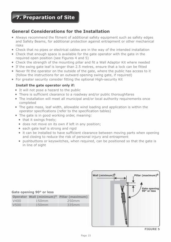
Gate opening 90° or less
Operator
V400150mm150mm 250mm
V500 335mm
Wall (minimum) Pillar (maximum)
FIGURE 5
Gate opening90° or less
Pillar (maximum)Wall (minimum)
Page 16
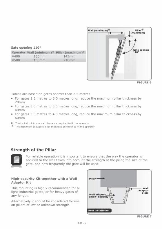
For reliable operation it is important to ensure that the way the operator is secured to the wall takes into account the strength of the pillar, the size of the gate, and how frequently the gate will be used:
Strength of the Pillar
High-security Kit together with a Wall Adaptor Kit
This mounting is highly recommended for all light-industrial gates, or for heavy gates of any length.
Alternatively it should be considered for use on pillars of low or unknown strength.
Pillar
FIGURE 7
Operator
V400150mm150mm 145mm
V500 210mm
Wall (minimum) Pillar (maximum)
Gate opening 110°
Pillar (maximum)
Gate opening110°
Wall (minimum)
FIGURE 6
Wall adaptor(high- security)
Wall adaptor
plate
Tables are based on gates shorter than 2.5 metres
For gates 2.5 metres to 3.0 metres long, reduce the maximum pillar thickness by 20mm
For gates 3.0 metres to 3.5 metres long, reduce the maximum pillar thickness by 40mm
For gates 3.5 metres to 4.0 metres long, reduce the maximum pillar thickness by 60mm
The typical minimum wall clearance required to fit the operator
The maximum allowable pillar thickness on which to fit the operator
Best installation
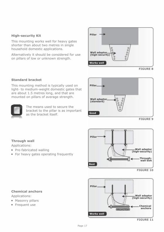
High-security Kit
This mounting works well for heavy gates shorter than about two metres in single household domestic applications.
Alternatively it should be considered for use on pillars of low or unknown strength.
Standard bracket
This mounting method is typically used on light- to medium-weight domestic gates that are about 1.5 metres long, and that are mounted on pillars of average strength.
FIGURE 8
FIGURE 9
The means used to secure the bracket to the pillar is as important as the bracket itself.
Through wall
Applications:
Pre-fabricated walling For heavy gates operating frequently
Chemical anchors
Applications:
Masonry pillars Frequent use
FIGURE 10
FIGURE 11
Page 17
Pillar
Wall adaptor(high-security)
Pillar
Wall adaptor(standard)
Pillar
Through-wall bolt
Pillar
Chemicalanchors
Wall adaptor(high-security)
Wall adaptor(high-security)
Works well
Good
Best
Works well
Page 18
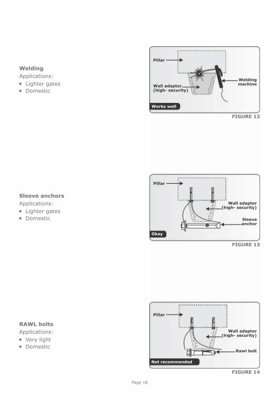
Welding
Applications:
Lighter gates Domestic
RAWL bolts
Applications:
Very light Domestic
FIGURE 14
FIGURE 12
Pillar
Welding machineWall adaptor
(high- security)
Sleeve anchors
Applications:
Lighter gates Domestic
FIGURE 13
Sleeve anchor
Pillar
Wall adaptor(high- security)
Wall adaptor(high- security)
Pillar
Rawl bolt
Not recommended
Okay
Works well
Page 19
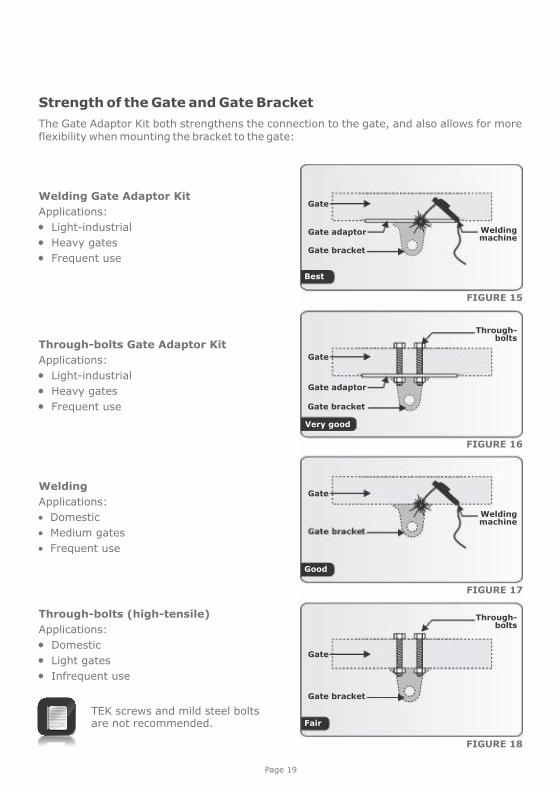
Strength of the Gate and Gate Bracket
The Gate Adaptor Kit both strengthens the connection to the gate, and also allows for more flexibility when mounting the bracket to the gate:
Through-bolts (high-tensile)
Applications:
Domestic
Light gates
Infrequent use
TEK screws and mild steel bolts are not recommended.
FIGURE 18
Welding Gate Adaptor Kit
Applications:
Light-industrial
Heavy gates
Frequent use
FIGURE 15
Gate
Gate bracket
Gate adaptor Welding machine
Through-bolts Gate Adaptor Kit
Applications:
Light-industrial
Heavy gates
Frequent use
FIGURE 16
Gate bracket
Gate adaptor
Gate
Through- bolts
Gate bracket
Welding
Applications:
Domestic
Medium gates
Frequent use
FIGURE 17
Gate
Welding machine
Gate
Through- bolts
Best
Good
Fair
Very good
Page 20
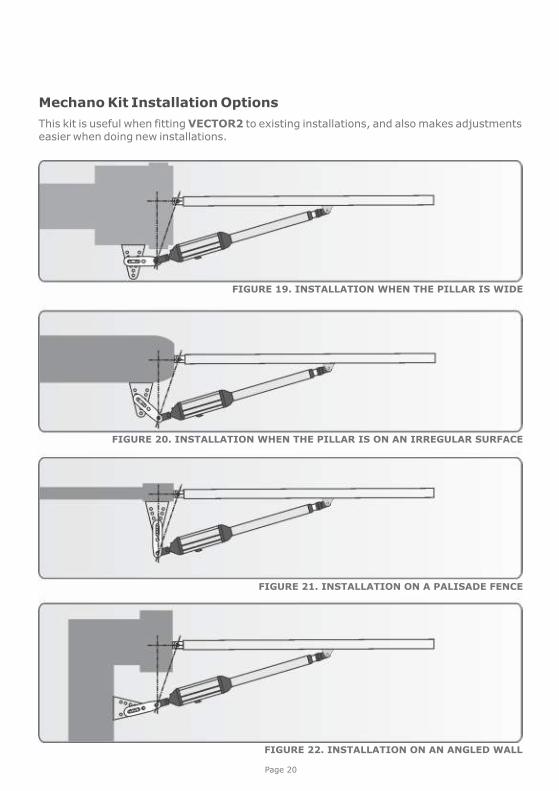
Mechano Kit Installation Options
This kit is useful when fitting VECTOR2 to existing installations, and also makes adjustments easier when doing new installations.
FIGURE 19. INSTALLATION WHEN THE PILLAR IS WIDE
FIGURE 20. INSTALLATION WHEN THE PILLAR IS ON AN IRREGULAR SURFACE
FIGURE 21. INSTALLATION ON A PALISADE FENCE
FIGURE 22. INSTALLATION ON AN ANGLED WALL
Page 21
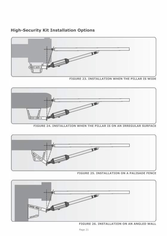
FIGURE 23. INSTALLATION WHEN THE PILLAR IS WIDE
FIGURE 24. INSTALLATION WHEN THE PILLAR IS ON AN IRREGULAR SURFACE
FIGURE 25. INSTALLATION ON A PALISADE FENCE
FIGURE 26. INSTALLATION ON AN ANGLED WALL
High-Security Kit Installation Options
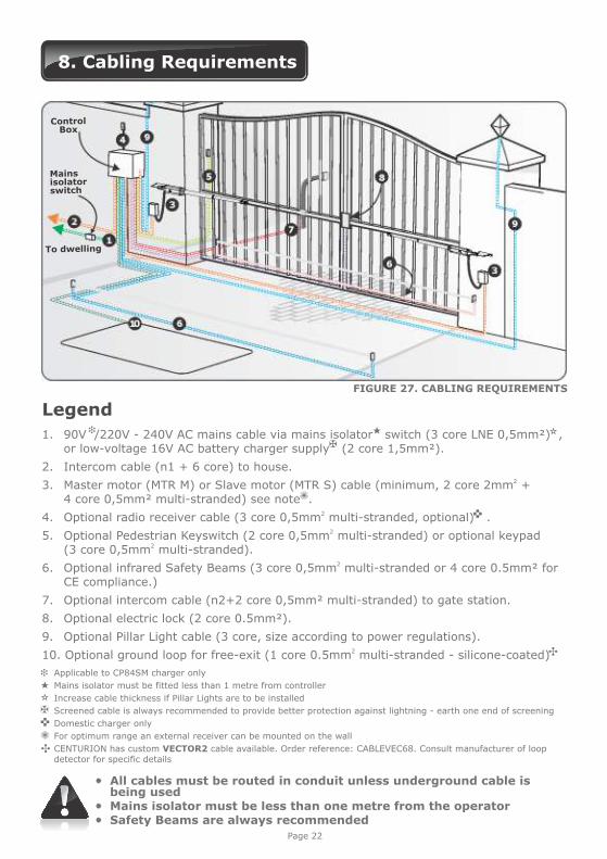
8. Cabling Requirements
FIGURE 27. CABLING REQUIREMENTS
Page 22
Legend
1. 90V /220V - 240V AC mains cable via mains isolator switch (3 core LNE 0,5mm²) , or low-voltage 16V AC battery charger supply (2 core 1,5mm²).
2. Intercom cable (n1 + 6 core) to house.23. Master motor (MTR M) or Slave motor (MTR S) cable (minimum, 2 core 2mm +
4 core 0,5mm² multi-stranded) see note .24. Optional radio receiver cable (3 core 0,5mm multi-stranded, optional) .
25. Optional Pedestrian Keyswitch (2 core 0,5mm multi-stranded) or optional keypad 2 (3 core 0,5mm multi-stranded).
26. Optional infrared Safety Beams (3 core 0,5mm multi-stranded or 4 core 0.5mm² for CE compliance.)
7. Optional intercom cable (n2+2 core 0,5mm² multi-stranded) to gate station.
8. Optional electric lock (2 core 0.5mm²).
9. Optional Pillar Light cable (3 core, size according to power regulations).210. Optional ground loop for free-exit (1 core 0.5mm multi-stranded - silicone-coated)
Applicable to CP84SM charger only
Mains isolator must be fitted less than 1 metre from controller
Increase cable thickness if Pillar Lights are to be installed
Screened cable is always recommended to provide better protection against lightning - earth one end of screening
Domestic charger only
For optimum range an external receiver can be mounted on the wall
CENTURION has custom VECTOR2 cable available. Order reference: CABLEVEC68. Consult manufacturer of loop detector for specific details
All cables must be routed in conduit unless underground cable is being used
Mains isolator must be less than one metre from the operator Safety Beams are always recommended
To dwelling
ControlBox
Mainsisolatorswitch

9. Critical Installation Checklist
The following is a list of critical requirements that must be adhered to in order to ensure reliable operation of your VECTOR2 operators:
Ensure that the wall bracket is securely anchored Make sure that the actuator’s maximum stroke is being utilised Only use VECTOR cable for the installation Leave a 350mm loop in the cable (refer to page 37) Fit an electromechanical or an electromagnetic gate lock if the leaf width is greater
than three metres Ensure that the opening and closing angles conform to the installation guidelines Ensure that your gate and operators are equipped to deal with wind loading (refer to
the table on page 36) Ensure that fixed mechanical endstops are fitted in the fully open position for outward
swinging gates
Page 23
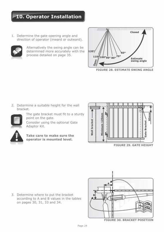
10. Operator Installation
1. Determine the gate opening angle and direction of operator (inward or outward).
Alternatively the swing angle can be
determined more accurately with the process detailed on page 35.
120°
100°110° 90° 80°70°
60°
Open
Closed
Estimate swing angle
3. Determine where to put the bracket according to A and B values in the tables on pages 30, 31, 33 and 34.
FIGURE 28. ESTIMATE SWING ANGLE
B
A
FIGURE 30. BRACKET POSITION
Page 24
2. Determine a suitable height for the wall bracket.
The gate bracket must fit to a sturdy point on the gate.
Consider using the optional Gate Adaptor Kit.
Take care to make sure the operator is mounted level.
FIGURE 29. GATE HEIGHT
Wall
bra
cket 85
mm
Gate
Bra
cket
Min
imu
m 1
25
mm
Use Mechano kitOperator must not foul against
bracket
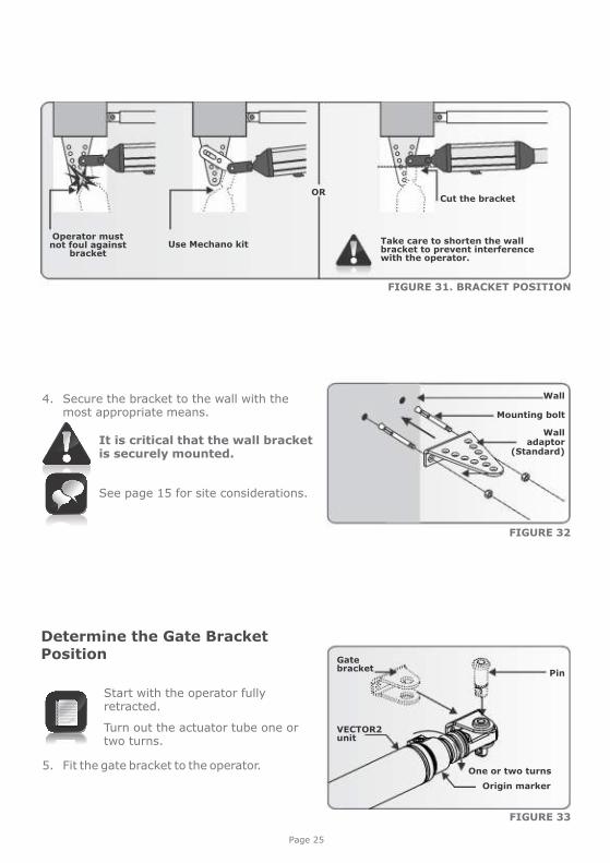
Take care to shorten the wall bracket to prevent interference with the operator.
ORCut the bracket
FIGURE 31. BRACKET POSITION
FIGURE 33
FIGURE 32
4. Secure the bracket to the wall with the most appropriate means.
It is critical that the wall bracket is securely mounted.
See page 15 for site considerations.
Wall adaptor
(Standard)
Wall
Mounting bolt
Determine the Gate BracketPosition
5. Fit the gate bracket to the operator.
Start with the operator fully retracted.
Turn out the actuator tube one or two turns.
One or two turns
VECTOR2unit
Pin
Gate bracket
Origin marker
Page 25
Page 26
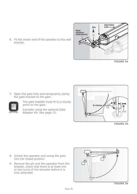
7. Open the gate fully and temporarily clamp the gate bracket to the gate.
The gate bracket must fit to a sturdy point on the gate.
Consider using the optional Gate Adaptor Kit. See page 13.
FIGURE 35
G-clamp
6. Fit the motor end of the operator to the wall bracket.
FIGURE 34
Wall adaptor(standard)
VECTOR2unitPin
FIGURE 36
8. Unlock the operator and swing the gate into the closed position.
9. Remove the pin and the operator from the bracket, check that there is at least one or two turns of the actuator before it is fully extended.
Page 27
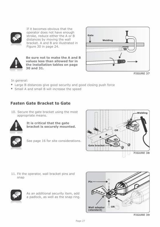
If it becomes obvious that the operator does not have enough stroke, reduce either the A or B distances by moving the wall bracket. A and B are illustrated in Figure 30 in page 24.
Be sure not to make the A and B values less than allowed for in the installation tables on page 30 and 31.
In general: Large B distances give good security and good closing push force Small A and small B will increase the speed
FIGURE 39
11. Fit the operator, wall bracket pins and snap
As an additional security item, add a padlock, as well as the snap ring.
FIGURE 37
Gate
FIGURE 38
Fasten Gate Bracket to Gate
OR
10. Secure the gate bracket using the most appropriate means.
It is critical that the gate bracket is securely mounted.
See page 16 for site considerations.
Gate bracket
Welding
Welding
ORWall adaptor(standard)
Pin
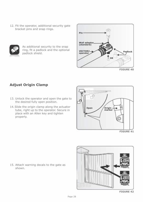
12. Fit the operator, additional security gate bracket pins and snap rings.
Page 28
FIGURE 40
FIGURE 42
As additional security to the snap ring, fit a padlock and the optional padlock shield.
15. Attach warning decals to the gate as shown.
OR
Pin
Wall adaptor(standard)
PadlockVECTOR2operator
FIGURE 41
Adjust Origin Clamp
Originmarker
13. Unlock the operator and open the gate to the desired fully open position.
14. Slide the origin clamp along the actuator tube, right up to the operator. Secure in place with an Allen key and tighten properly.
Open
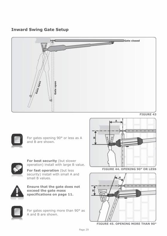
For gates opening more than 90° as A and B are shown.
For gates opening 90° or less as A and B are shown.
Page 29
FIGURE 43
FIGURE 44. OPENING 90° OR LESS
Inward Swing Gate Setup
FIGURE 45. OPENING MORE THAN 90°
For best security (but slower operation) install with large B value.
For fast operation (but less security) install with small A and small B values.
Ensure that the gate does not exceed the gate mass specifications on page 11.
Gate closed
Gate
open
Gate
op
en
Page 30
FIGURE 47
FIGURE 46
1400mm extended
1000mm retracted
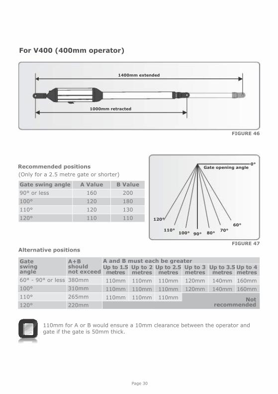
For V400 (400mm operator)
120°
100°110°
90° 80°70°
60°
Gate opening angle0°
Gate swing angle
90° or less
100°
110°
120°
B Value
200
180
130
110
A Value
160
120
120
110
(Only for a 2.5 metre gate or shorter)
Recommended positions
110mm for A or B would ensure a 10mm clearance between the operator and gate if the gate is 50mm thick.
Alternative positions
Gate swing angle
60° - 90° or less
100°
110°
120°
A+B should not exceed
380mm
310mm
265mm
220mm
A and B must each be greater Up to 1.5 metres
110mm
110mm
110mm
Up to 2 metres
110mm
110mm
110mm
Up to 2.5 metres
110mm
110mm
110mm
Up to 3 metres
120mm
120mm
Up to 3.5 metres
140mm
140mm
Up to 4 metres
160mm
160mm
Not recommended
Page 31
FIGURE 48
FIGURE 49
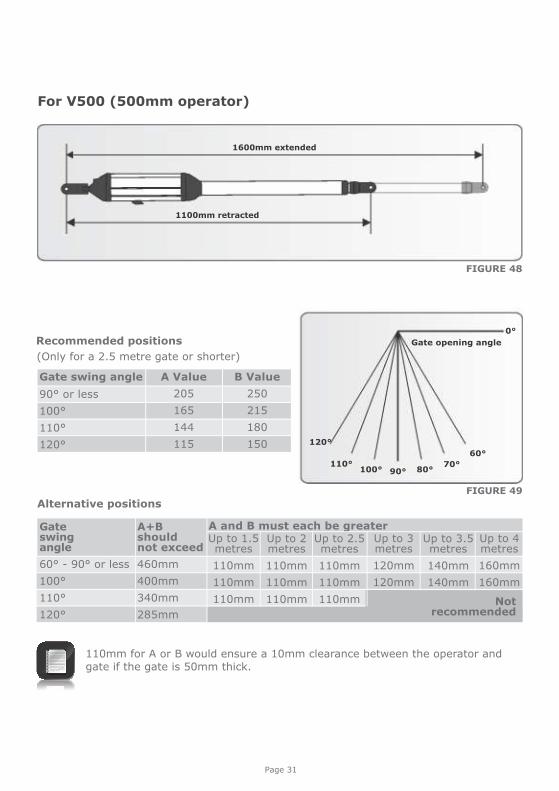
For V500 (500mm operator)
120°
100°110°
90° 80°70°
60°
Gate opening angle
0°
Gate swing angle
90° or less
100°
110°
120°
A Value
205
165
144
115
B Value
250
215
180
150
(Only for a 2.5 metre gate or shorter)
Recommended positions
Alternative positions
110mm for A or B would ensure a 10mm clearance between the operator and gate if the gate is 50mm thick.
Gate swing angle
60° - 90° or less
100°
110°
120°
A+B should not exceed
460mm
400mm
340mm
285mm
A and B must each be greater Up to 1.5 metres
110mm
110mm
110mm
Up to 2 metres
110mm
110mm
110mm
Up to 2.5 metres
110mm
110mm
110mm
Up to 3 metres
120mm
120mm
Up to 3.5 metres
140mm
140mm
Up to 4 metres
160mm
160mm
Not recommended
1600mm extended
1100mm retracted
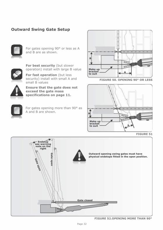
For gates opening 90° or less as A and B are as shown.
FIGURE 52.OPENING MORE THAN 90°
FIGURE 50. OPENING 90° OR LESS
For best security (but slower operation) install with large B value
For fast operation (but less security) install with small A and small B values
Ensure that the gate does not exceed the gate mass specifications on page 11.
For gates opening more than 90° as A and B are shown.
Endstop see warningnote on the
right
Gate closed
Gate
open
Gate
op
en
Outward Swing Gate Setup
B
A
B
Outward opening swing gates must have physical endstops fitted in the open position.
FIGURE 51
Page 32
Make up bracketto suit
Make up bracketto suit A

Page 33
FIGURE 53
FIGURE 54
1400mm extended
1000mm retracted
For V400 (400mm operator) outward
120°
100°110°
90° 80°70°
60°
Gate opening angle 0°
Gate swing angle
90° or less
100°
110°
120°
A Value
173
145
120
106
B Value
191
160
130
114
(Only for a 2.5 metre gate or shorter)
Recommended positions
Alternative positions
110mm for A or B would ensure a 10mm clearance between the operator and gate if the gate is 50mm thick.
Gate swing angle
60° - 90° or less
100°
110°
120°
A+B should not exceed
365mm
310mm
265mm
220mm
A and B must each be greater Up to 1.5 metres
110mm
110mm
110mm
Up to 2 metres
110mm
110mm
110mm
Up to 2.5 metres
110mm
110mm
110mm
Up to 3 metres
120mm
120mm
Up to 3.5 metres
140mm
140mm
Up to 4 metres
160mm
160mm
Not recommended
Page 34
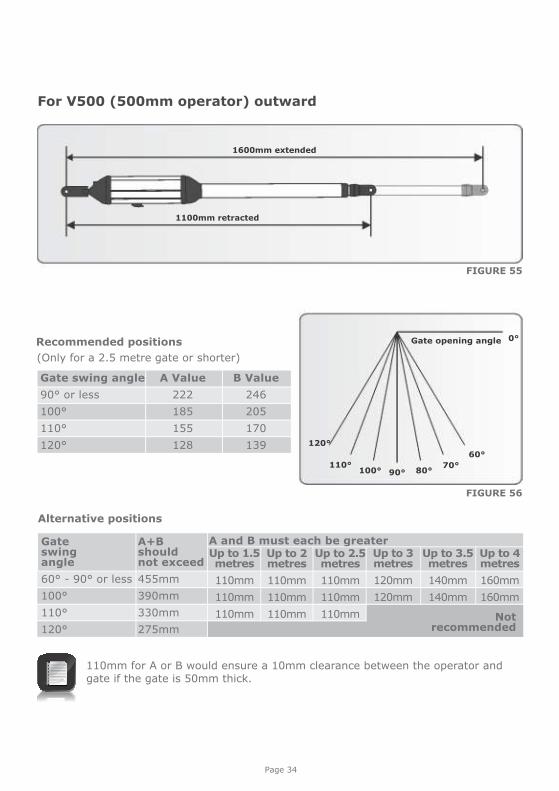
FIGURE 55
FIGURE 56
1600mm extended
1100mm retracted
For V500 (500mm operator) outward
120°
100°110°
90° 80°70°
60°
Gate opening angle 0°
Gate swing angle
90° or less
100°
110°
120°
A Value
222
185
155
128
B Value
246
205
170
139
(Only for a 2.5 metre gate or shorter)
Recommended positions
Alternative positions
110mm for A or B would ensure a 10mm clearance between the operator and gate if the gate is 50mm thick.
Gate swing angle
60° - 90° or less
100°
110°
120°
A+B should not exceed
455mm
390mm
330mm
275mm
A and B must each be greater Up to 1.5 metres
110mm
110mm
110mm
Up to 2 metres
110mm
110mm
110mm
Up to 2.5 metres
110mm
110mm
110mm
Up to 3 metres
120mm
120mm
Up to 3.5 metres
140mm
140mm
Up to 4 metres
160mm
160mm
Not recommended
Page 35
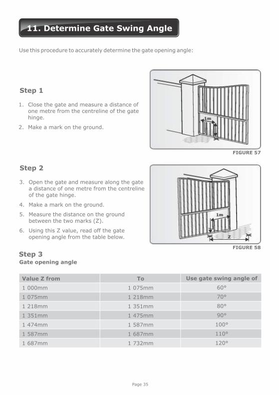
11. Determine Gate Swing Angle
Use this procedure to accurately determine the gate opening angle:
1. Close the gate and measure a distance of one metre from the centreline of the gate hinge.
2. Make a mark on the ground.
Step 1
3. Open the gate and measure along the gate a distance of one metre from the centreline of the gate hinge.
4. Make a mark on the ground.
5. Measure the distance on the ground between the two marks (Z).
6. Using this Z value, read off the gate opening angle from the table below.
Step 2
Step 3
Use gate swing angle of
60°
70°
80°
90°
100°
110°
120°
Value Z from
1 000mm
1 075mm
1 218mm
1 351mm
1 474mm
1 587mm
1 687mm
To
1 075mm
1 218mm
1 351mm
1 475mm
1 587mm
1 687mm
1 732mm
FIGURE 57
FIGURE 58
Gate opening angle

Page 36
12. Allowable Wind Load
Wind speeds for which operator will still operate the gate (for V400 or V500 operators)
Value of A or B dimension once installed
100mm
140mm
180mm
220mm
260mm
300mm
340mm
Up to 1.5 metres
94km/h
119km/h
138km/h
156km/h
171km/h
186km/h
199km/h
Up to 2 metres
66km/h
85km/h
101km/h
114km/h
126km/h
137km/h
147km/h
Up to 2.5 metres
48km/h
65km/h
78km/h
89km/h
99km/h
108km/h
116km/h
Up to 3 metres
44km/h
57km/h
67km/h
76km/h
84km/h
91km/h
98km/h
Up to 3.5 metres
41km/h
51km/h
60km/h
67km/h
74km/h
80km/h
86km/h
Up to 4 metres
37km/h
46km/h
53km/h
60km/h
65km/h
71km/h
76km/h
For a 25% covered gate: (palisades, etc.) x 1.8 metre high
Gate lengths:
See page 24 or 2 for installation details 5
An electric lock must be fitted
Wind speeds for which operator will still operate the gate (for V400 or V500 operators)
Value of A or B dimension once installed
100mm
140mm
180mm
220mm
260mm
300mm
340mm
Up to 1.5 metres
47km/h
59km/h
69km/h
78km/h
86km/h
93km/h
100km/h
Up to 1.5 metres
47km/h
59km/h
69km/h
78km/h
86km/h
93km/h
100km/h
Up to 2 metres
33km/h
43km/h
50km/h
57km/h
63km/h
68km/h
74km/h
Up to 2.5 metres
24km/h
32km/h
39km/h
44km/h
49km/h
54km/h
58km/h
Up to 3 metres
22km/h
28km/h
34km/h
38km/h
42km/h
46km/h
49km/h
Up to 4 metres
19km/h
23km/h
27km/h
30km/h
33km/h
35km/h
38km/h
For a 100% covered gate: (Fully clad gates, etc.) x 1.8 metre high
Gate lengths:
See page 24 or 2 for installation details 5
An electric lock must be fitted
Page 37
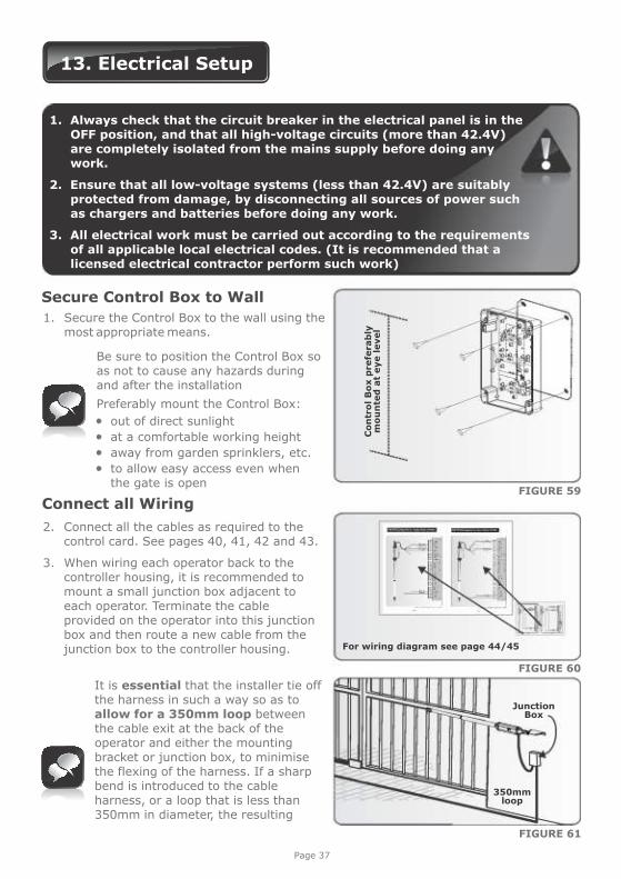
13. Electrical Setup
Secure Control Box to Wall
1. Secure the Control Box to the wall using the most appropriate means.
Be sure to position the Control Box so as not to cause any hazards during and after the installation
Preferably mount the Control Box:
out of direct sunlight at a comfortable working height away from garden sprinklers, etc. to allow easy access even when
the gate is open
For wiring diagram see page 44/45
Connect all Wiring
2. Connect all the cables as required to the control card. See pages 40, 41, 42 and 43.
3. When wiring each operator back to the controller housing, it is recommended to mount a small junction box adjacent to each operator. Terminate the cable provided on the operator into this junction box and then route a new cable from the junction box to the controller housing.
1. Always check that the circuit breaker in the electrical panel is in the OFF position, and that all high-voltage circuits (more than 42.4V) are completely isolated from the mains supply before doing any work.
2. Ensure that all low-voltage systems (less than 42.4V) are suitably protected from damage, by disconnecting all sources of power such as chargers and batteries before doing any work.
3. All electrical work must be carried out according to the requirements of all applicable local electrical codes. (It is recommended that a licensed electrical contractor perform such work)
FIGURE 59
FIGURE 60
FIGURE 61
It is essential that the installer tie off the harness in such a way so as to allow for a 350mm loop between the cable exit at the back of the operator and either the mounting bracket or junction box, to minimise the flexing of the harness. If a sharp bend is introduced to the cable harness, or a loop that is less than 350mm in diameter, the resulting
Junction Box
350mmloop
Co
ntr
ol B
ox p
refe
rab
ly
mo
un
ted
at
eye level
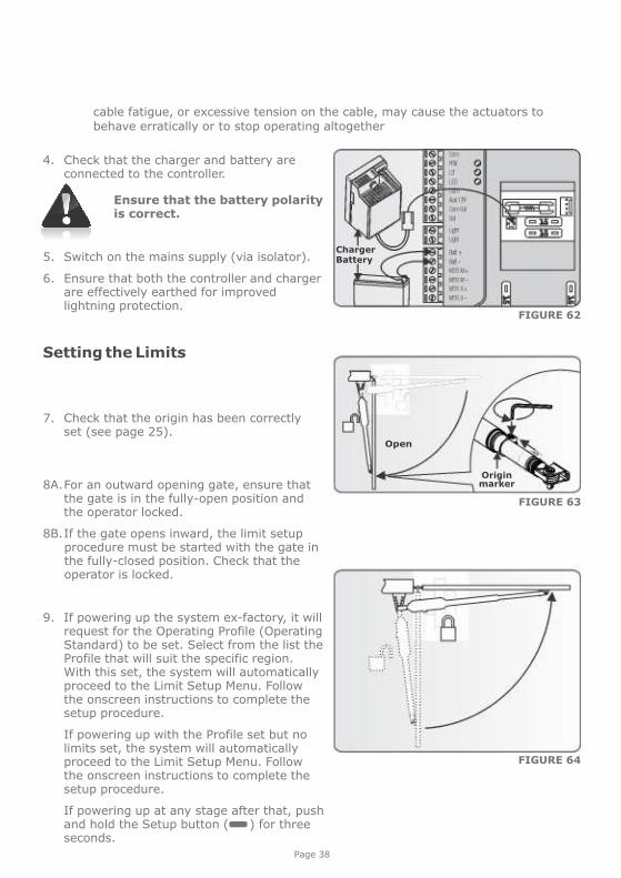
cable fatigue, or excessive tension on the cable, may cause the actuators to behave erratically or to stop operating altogether
Page 38
4. Check that the charger and battery are connected to the controller.
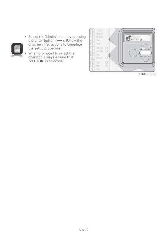
7. Check that the origin has been correctly set (see page 25).
Setting the Limits
8A. For an outward opening gate, ensure that the gate is in the fully-open position and the operator locked.
8B. If the gate opens inward, the limit setup procedure must be started with the gate in the fully-closed position. Check that the operator is locked.
9. If powering up the system ex-factory, it will request for the Operating Profile (Operating Standard) to be set. Select from the list the Profile that will suit the specific region. With this set, the system will automatically proceed to the Limit Setup Menu. Follow the onscreen instructions to complete the setup procedure.
If powering up with the Profile set but no limits set, the system will automatically proceed to the Limit Setup Menu. Follow the onscreen instructions to complete the setup procedure.
If powering up at any stage after that, push and hold the Setup button ( ) for three seconds.
FIGURE 64
Ensure that the battery polarity is correct.
5. Switch on the mains supply (via isolator).
6. Ensure that both the controller and charger are effectively earthed for improved lightning protection.
ChargerBattery
FIGURE 62
Originmarker
Open
FIGURE 63
Page 39
FIGURE 65
Select the ‘Limits’ menu by pressing the enter button ( ). Follow the onscreen instructions to complete the setup procedure.
When prompted to select the operator, always ensure that 'VECTOR' is selected.
IR
B T
x
12V/24V +
12V/24V -
12V/24V -
IR
B R
eceiv
er
COM
12V/24V +
NC
NO
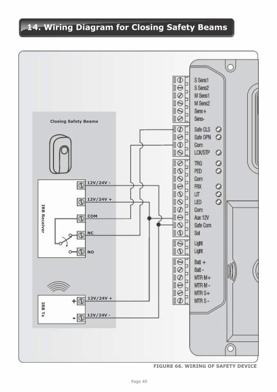
Closing Safety Beams
FIGURE 66. WIRING OF SAFETY DEVICE
Page 40
14. Wiring Diagram for Closing Safety Beams
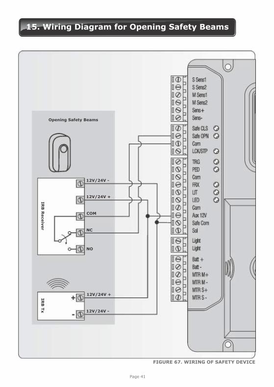
FIGURE 67. WIRING OF SAFETY DEVICE
Page 41
Opening Safety Beams
15. Wiring Diagram for Opening Safety Beams
IR
B T
xIR
B R
eceiv
er
12V/24V +
12V/24V -
12V/24V -
COM
12V/24V +
NC
NO
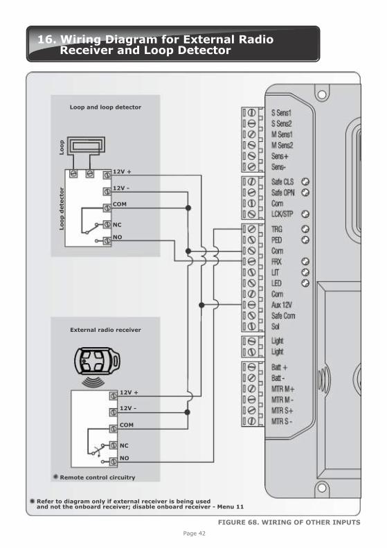
16. Wiring Diagram for External Radio Receiver and Loop Detector
Loop and loop detector
Remote control circuitry
External radio receiver
FIGURE 68. WIRING OF OTHER INPUTS
Page 42
12V +
12V -
COM
NC
NO
Refer to diagram only if external receiver is being used and not the onboard receiver; disable onboard receiver - Menu 11
12V -
12V +
COM
NO
NC
Lo
op
dete
cto
rLo
op
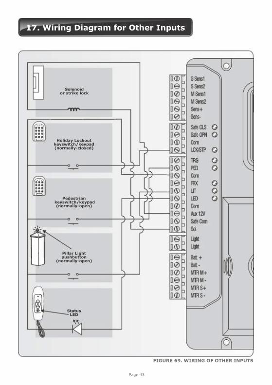
17. Wiring Diagram for Other Inputs
Holiday Lockout keyswitch/keypad(normally-closed)
Pedestrian keyswitch/keypad
(normally-open)
Pillar Light pushbutton
(normally-open)
Status LED
AUX
Solenoid or strike lock
FIGURE 69. WIRING OF OTHER INPUTS
Page 43
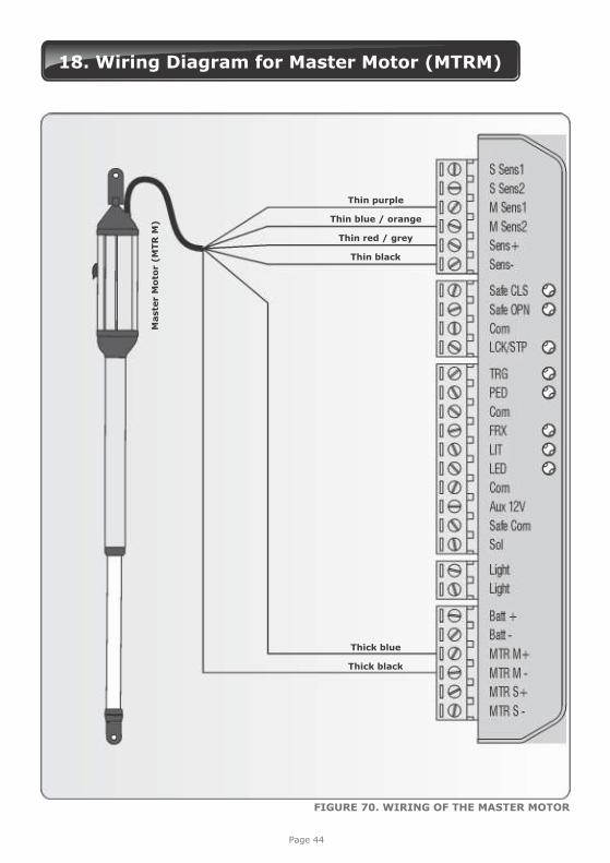
18. Wiring Diagram for Master Motor (MTRM)
Thin purple
Thin red / grey
Thick blue
Thick black
Thin blue / orange
Thin black
Maste
r M
oto
r (M
TR
M)
FIGURE 70. WIRING OF THE MASTER MOTOR
Page 44
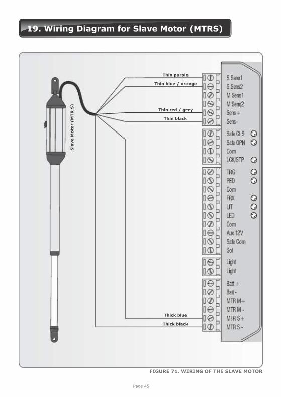
19. Wiring Diagram for Slave Motor (MTRS)
Thin purple
Thin red / grey
Thick blue
Thick black
Thin blue / orange
Thin black
Sla
ve M
oto
r (M
TR
S)
FIGURE 71. WIRING OF THE SLAVE MOTOR
Page 45
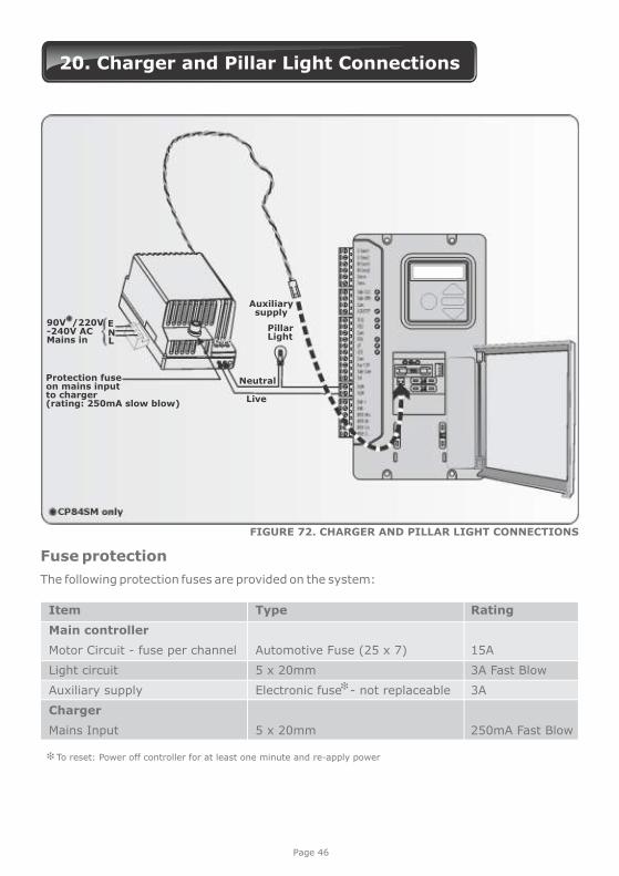
20. Charger and Pillar Light Connections
90V /220V-240V ACMains in
ENL
Protection fuse on mains inputto charger (rating: 250mA slow blow)
Auxiliary supply
Pillar Light
Neutral
Live
NL E
Fuse protection
The following protection fuses are provided on the system:
Item
Main controller
Motor Circuit - fuse per channel
Light circuit
Auxiliary supply
Charger
Mains Input
Type
Automotive Fuse (25 x 7)
5 x 20mm
Electronic fuse - not replaceable
5 x 20mm
Rating
15A
3A Fast Blow
3A
250mA Fast Blow
To reset: Power off controller for at least one minute and re-apply power
FIGURE 72. CHARGER AND PILLAR LIGHT CONNECTIONS
Page 46
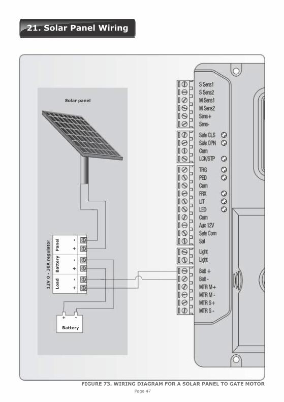
21. Solar Panel Wiring
12
V 0
- 3
0A
reg
ula
tor
Solar panel
Lo
ad
++
+-
--
Batt
ery
Pan
el
+ -
Battery
Page 47
FIGURE 73. WIRING DIAGRAM FOR A SOLAR PANEL TO GATE MOTOR
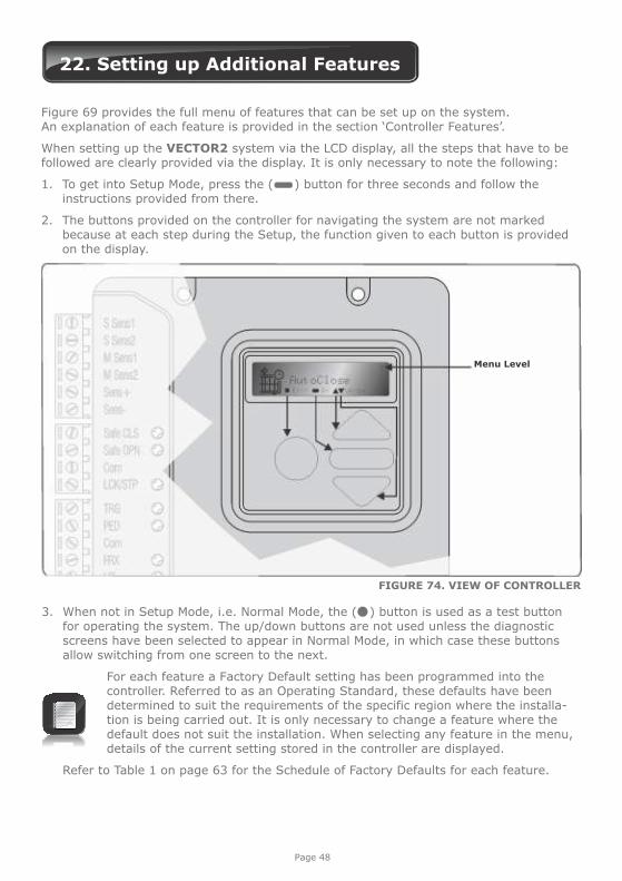
22. Setting up Additional Features
Figure 69 provides the full menu of features that can be set up on the system. An explanation of each feature is provided in the section ‘Controller Features’.
When setting up the VECTOR2 system via the LCD display, all the steps that have to be followed are clearly provided via the display. It is only necessary to note the following:
1. To get into Setup Mode, press the ( ) button for three seconds and follow the instructions provided from there.
2. The buttons provided on the controller for navigating the system are not marked because at each step during the Setup, the function given to each button is provided on the display.
Page 48
FIGURE 74. VIEW OF CONTROLLER
3. When not in Setup Mode, i.e. Normal Mode, the ( ) button is used as a test button for operating the system. The up/down buttons are not used unless the diagnostic screens have been selected to appear in Normal Mode, in which case these buttons allow switching from one screen to the next.
For each feature a Factory Default setting has been programmed into the controller. Referred to as an Operating Standard, these defaults have been determined to suit the requirements of the specific region where the installa-tion is being carried out. It is only necessary to change a feature where the default does not suit the installation. When selecting any feature in the menu, details of the current setting stored in the controller are displayed.
Refer to Table 1 on page 63 for the Schedule of Factory Defaults for each feature.
Menu LevelMenu LevelMenu Level
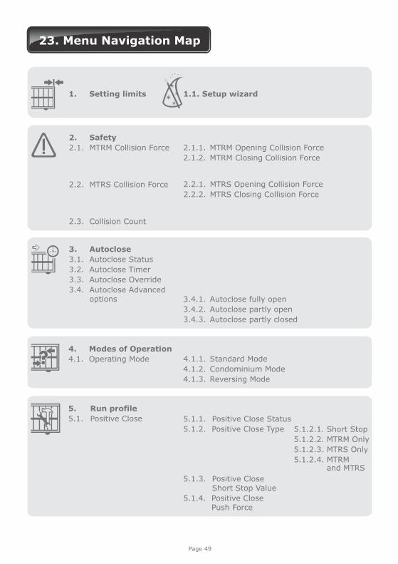
23. Menu Navigation Map
1. Setting limits 1.1. Setup wizard
Page 49
2. Safety
2.1. MTRM Collision Force
2.2. MTRS Collision Force
2.3. Collision Count
2.1.1. MTRM Opening Collision Force
2.1.2. MTRM Closing Collision Force
3. Autoclose
3.1. Autoclose Status
3.2. Autoclose Timer
3.3. Autoclose Override
3.4. Autoclose Advanced options 3.4.1. Autoclose fully open
3.4.2. Autoclose partly open
3.4.3. Autoclose partly closed
4. Modes of Operation
4.1. Operating Mode 4.1.1. Standard Mode
4.1.2. Condominium Mode
4.1.3. Reversing Mode
5. Run profile
5.1. Positive Close 5.1.1. Positive Close Status
5.1.2. Positive Close Type
5.1.3. Positive Close Short Stop Value
5.1.4. Positive Close Push Force
5.1.2.1. Short Stop
5.1.2.2. MTRM Only
5.1.2.3. MTRS Only
5.1.2.4. MTRM and MTRS
2.2.1. MTRS Opening Collision Force
2.2.2. MTRS Closing Collision Force
Page 50
2.1.1. Leaf Delay Status
2.2.1. Leaf Delay Value
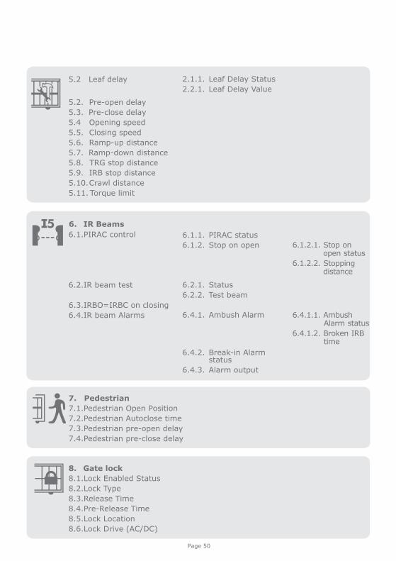
5.2 Leaf delay
5.2. Pre-open delay
5.3. Pre-close delay
5.4 Opening speed
5.5. Closing speed
5.6. Ramp-up distance
5.7. Ramp-down distance
5.8. TRG stop distance
5.9. IRB stop distance
5.10. Crawl distance
5.11. Torque limit
7. Pedestrian
7.1.Pedestrian Open Position
7.2.Pedestrian Autoclose time
7.3.Pedestrian pre-open delay
7.4.Pedestrian pre-close delay
6. IR Beams
6.1.1. PIRAC status
6.1.2. Stop on open
6.2.1. Status
6.2.2. Test beam
6.4.1. Ambush Alarm
6.4.2. Break-in Alarm status
6.4.3. Alarm output
6.1.2.1. Stop on open status
6.1.2.2. Stopping distance
6.4.1.1. Ambush Alarm status
6.4.1.2. Broken IRB time
8. Gate lock
8.1.Lock Enabled Status
8.2.Lock Type
8.3.Release Time
8.4.Pre-Release Time
8.5.Lock Location
8.6.Lock Drive (AC/DC)
6.1.PIRAC control
6.2.IR beam test
6.3.IRBO=IRBC on closing
6.4.IR beam Alarms
Page 51
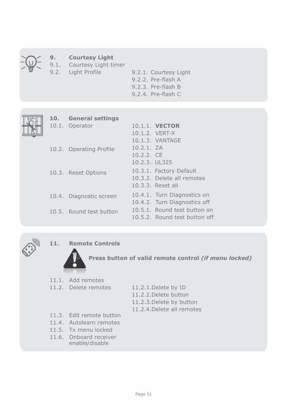
11. Remote Controls
Press button of valid remote control (if menu locked)
11.2.1.Delete by ID
11.2.2.Delete button
11.2.3.Delete by button
11.2.4.Delete all remotes
9. Courtesy Light
9.1. Courtesy Light timer
9.2. Light Profile 9.2.1. Courtesy Light
9.2.2. Pre-flash A
9.2.3. Pre-flash B
9.2.4. Pre-flash C
10. General settings
10.1. Operator
10.2. Operating Profile
10.3. Reset Options
10.4. Diagnostic screen
10.5. Round test button
10.1.1. VECTOR
10.1.2. VERT-X
10.1.3. VANTAGE
10.2.1. ZA
10.2.2. CE
10.2.3. UL325
10.3.1. Factory Default
10.3.2. Delete all remotes
10.3.3. Reset all
10.4.1. Turn Diagnostics on
10.4.2. Turn Diagnostics off
10.5.1. Round test button on
10.5.2. Round test button off
11.1. Add remotes
11.2. Delete remotes
11.3. Edit remote button
11.4. Autolearn remotes
11.5. Tx menu locked
11.6. Onboard receiver enable/disable
Page 52
24. Controller Features
This level should only be used if additional safety measures are taken (e.g. Infrared Safety Beams, etc.). Collision Force can be set independently per direction of travel.
Menu 2 - Safety (Collision Force)
1. Collision Force
If the gate is obstructed, the internal collision circuitry will activate.
The response of the system to a collision will vary, depending on the Profile selected (Operating Standard, e.g. ZA). Responses can vary from the gate stopping, to the gate reversing. The Collision Force can be set from minimum to maximum in five discrete steps.
A sixth step will disable collision sensing entirely, allowing maximum force to be achieved. Under this condition, the motor will continue running until it stalls, at which point a collision will be detected.
Menu 3 - Autoclose
1. Autoclose status
When turned on, the Autoclose feature has the function of automatically closing the gate after a preset Autoclose time. The Autoclose feature is automatically turned on when the controller is set for Condominium Mode.
2. Autoclose time
The Autoclose time can be set anywhere from 1 to 255 seconds.
3. Autoclose Override
It is possible for the user to temporarily turn off Autoclose when the Mode of Operation is Standard or Reversing. To activate Autoclose Override, the Trg input must be activated and maintained for a period longer than the time set for the Autoclose Override Time.
The gate response will be to start opening on the Trg trigger, and then to stop as soon as the Autoclose Override feature is activated. On clearing of the Trg input, the gate will continue opening until fully open. The Autoclose feature is now off and the gate will remain open indefinitely.
The next signal received on Trg will clear the Autoclose Override feature, close the gate, and set the Autoclose feature back to normal.
4. Autoclose Advanced Options
The conditions under which the gate will automatically close can be set within the Advanced Autoclose options menu:
2. Collision Count
A counter monitors the number of collisions that the gate experiences before it reaches the fully closed position. If the value exceeds the value set in the Multiple Collision Counter the controller shuts down until the next valid trigger is received. As an indication, the status LED will flash four times every two seconds. The Multiple Collision fault indication will continue to flash indefinitely or until a valid trigger has been received.
Page 53
4.1. Autoclose on open - automatically close the gate if it has reached the fully open position
4.2. Autoclose on partly open - automatically close the gate if it is stopped while opening, but before reaching the fully opened position.
4.3. Autoclose on partly closed - automatically close the gate if it is stopped while closing, but before reaching the fully closed position.
More than one advanced option can be selected.
Menu 4 - Modes of Operation
It is possible to select the following Modes of Operation: Standard, Condominium, and Reversing Mode. All modes are triggered by closing a normally-open contact between the Trg input terminal and the Com terminal.
1. Standard Mode
When stationary, a trigger impulse on Trg will cause the gate to either open or close. On a moving gate, a trigger impulse on Trg will stop the gate. The next impulse on Trg will cause the gate to reverse its direction of travel, i.e. the action is start-stop-reverse.
2. Condominium Mode
A trigger impulse on Trg will open the gate under all conditions. If it were closing, it would stop and reverse to open. In this Mode of Operation, the only way to close the gate is with the Autoclose feature, which is automatically activated when Condominium Mode is selected.
3. Reversing Mode
A trigger impulse on Trg will reverse the direction of a moving gate. If it were closing, it would stop and immediately begin opening. If it were opening, it would stop and immediately begin closing.
Menu 5 - Run Profile
1. Positive Close Mode (PCM)
Setting Positive Close Mode to ON will allow the gate to drive up hard to the closed endstop without causing the collision circuitry to operate. This feature operates only during the last few millimetres of gate travel in Closing Mode.
2. Positive close type
PCM can be applied to one of the following:
Short Stop (further explanation follows) Master Motor (MTRM) Slave Motor (MTRS) Both Master and Slave Motors
Page 54
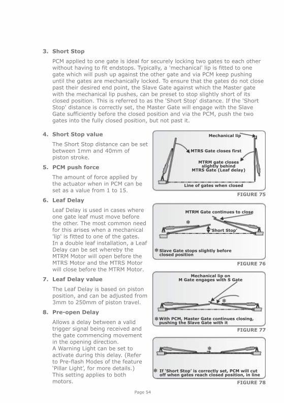
3. Short Stop
PCM applied to one gate is ideal for securely locking two gates to each other without having to fit endstops. Typically, a 'mechanical' lip is fitted to one gate which will push up against the other gate and via PCM keep pushing until the gates are mechanically locked. To ensure that the gates do not close past their desired end point, the Slave Gate against which the Master gate with the mechanical lip pushes, can be preset to stop slightly short of its closed position. This is referred to as the 'Short Stop' distance. If the 'Short Stop' distance is correctly set, the Master Gate will engage with the Slave Gate sufficiently before the closed position and via the PCM, push the two gates into the fully closed position, but not past it.
4. Short Stop value
The Short Stop distance can be set between 1mm and 40mm of piston stroke.
5. PCM push force
The amount of force applied by the actuator when in PCM can be set as a value from 1 to 15.
6. Leaf Delay
Leaf Delay is used in cases where one gate leaf must move before the other. The most common need for this arises when a mechanical 'lip' is fitted to one of the gates. In a double leaf installation, a Leaf Delay can be set whereby the MTRM Motor will open before the MTRS Motor and the MTRS Motor will close before the MTRM Motor.
7. Leaf Delay value
The Leaf Delay is based on piston position, and can be adjusted from 3mm to 250mm of piston travel.
8. Pre-open Delay
Allows a delay between a valid trigger signal being received and the gate commencing movement in the opening direction. A Warning Light can be set to activate during this delay. (Refer to Pre-flash Modes of the feature ‘Pillar Light’, for more details.) This setting applies to both motors. FIGURE 78
Mechanical lip on M Gate engages with S Gate
With PCM, Master Gate continues closing, pushing the Slave Gate with it
FIGURE 77
FIGURE 76
MTRM Gate continues to close
‘Short Stop’
Slave Gate stops slightly before closed position
Line of gates when closed
MTRM gate closes slightly behind
MTRS Gate (Leaf delay)
MTRS Gate closes first
Mechanical lip
FIGURE 75
If ‘Short Stop’ is correctly set, PCM will cut off when gates reach closed position, in line
InsideClosing Beam
Gates will not close
Outside Closing Beam
Page 55
9. Pre-close Delay
Allows a delay between a valid trigger signal being received and the gate commencing movement in the closing direction. The delay will also occur if the gate is set to close automatically. A Warning Light can be set to activate during this delay. (Refer to Pre-flash Modes of the feature ‘Pillar Light’, for more details). This setting applies to both operators.
10. Opening Speed
Sets the maximum piston opening speed in millimeters per second. This setting applies to both operators.
11. Closing Speed
Sets the maximum piston closing speed in millimeters per second. This setting applies to both operators.
12. Ramp-up Distance Sets the Ramp-up Distance in millimeters of travel of the piston when starting. This setting applies to both operators.
13. Ramp-down Distance Sets the Ramp-down Distance in millimeters of travel of the piston when stopping. This setting applies to both operators.
14. Crawl Distance Sets the final Crawl Distance in millimeters of travel of the piston when reaching an endpoint. This setting applies to both operators.
15. Push Force Limit Sets the maximum push force delivered by the operators. The maximum setting is a value of 15 and the minimum is four. This is useful in cases where limited push force is required. This setting applies to both operators.
Menu 6 - IR beams
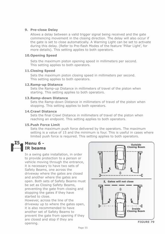
In a swing gate installation, in order to provide protection to a person or vehicle moving through the entrance, it is necessary to have two sets of Safety Beams, one across the driveway where the gates are closed and another where the gates are open. Both sets of Safety Beams must be set as Closing Safety Beams, preventing the gate from closing and stopping the gates if they have started to close.However, across the line of the driveway up to where the gates open, it is also recommended to have another set of Safety Beams to prevent the gate from opening if they are closed and stop if they are opening. FIGURE 79
Page 56
Two independent normally-closed inputs are provided for Opening and Closing Safety Beams.
An interrupted closing beam will prevent the gates from closing and stop and reverse the gates back to the open position if already opening. Vice-versa for an opening beam.
Additional beam functionality is provided:
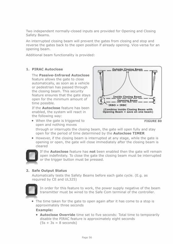
1. PIRAC Autoclose
The Passive-Infrared Autoclose feature allows the gate to close automatically, as soon as a vehicle or pedestrian has passed through the closing beam. This security feature ensures that the gate stays open for the minimum amount of time possible.
If the Autoclose feature has been enabled, the system will react in the following way:
When the gate is triggered to open and nothing moves
Outside Closing Beam
Inside Closing Beam
Opening Beam
IRBO = IRBC
(Combine inside Closing Beam with Opening Beam = save on one beam)
FIGURE 80
through or interrupts the closing beam, the gate will open fully and stay open for the period of time determined by the Autoclose TIMER
However, if the closing beam is interrupted at any stage, while the gate is opening or open, the gate will close immediately after the closing beam is cleared
If the Autoclose feature has not been enabled then the gate will remain open indefinitely. To close the gate the closing beam must be interrupted or the trigger button must be pressed.
2. Safe Output Status
Automatically tests the Safety Beams before each gate cycle. (E.g. as required by CE and UL325)
In order for this feature to work, the power supply negative of the beam transmitter must be wired to the Safe Com terminal of the controller.
The time taken for the gate to open again after it has come to a stop is approximately three seconds
Example:
Autoclose Override time set to five seconds: Total time to temporarily disable the PIRAC feature is approximately eight seconds (5s + 3s = 8 seconds)
3. IR Beam Test (only compatible with i5 Safety Beams; not compatible with wireless Safety Beams).
Automatically tests the Safety Beams before each gate cycle. (E.g. as required by CE.)
In order for this feature to work, the power supply negative of the beam transmitter must be wired to the Safe Com terminal of the controller.
4. IRBO=IRBC
Configures the opening beam to act as a closing beam while the gates are closing. This allows one set of Safety Beams to be used across the line of the driveway up to where the gates open.
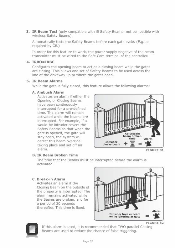
5. IR Beam Alarms
While the gate is fully closed, this feature allows the following alarms:
FIGURE 81
AlarmIntruder
blocks beam
Adjustable beam broken
time
A. Ambush Alarm Activates an alarm if either the Opening or Closing Beams have been continuously interrupted for a pre-defined time. The alarm will remain activated while the beams are interrupted. For example, if a would-be intruder covers the Safety Beams so that when the gate is opened, the gate will stay open, the system will detect this beam override taking place and set off an alarm.
B. IR Beam Broken Time
The time that the Beams must be interrupted before the alarm is activated.
Intruder breaks beamwhile loitering at gate
Alarm
C. Break-in Alarm Activates an alarm if the
Closing Beam on the outside of the property is interrupted. The alarm remains activated while the Beams are broken, and for a period of 30 seconds thereafter. This time is fixed.
If this alarm is used, it is recommended that TWO parallel Closing Beams are used to reduce the chance of false triggering.
FIGURE 82
Page 57
Page 58
D. Alarm output
The system can be configured to operate one of the following outputs provided on the controller:
Onboard buzzer - emits a continuous tone
Pillar / Courtesy Light contact (potential-free normally-open contact, fuse-protected - 5A)
Aux IO (this is an open collector drive, maximum current draw 3A, not fuse-protected)
Safety beam common (this is an open collector drive, maximum current draw 3A, not fuse-protected)
Status LED output (operate up to three LEDs in parallel or interface with the CP78 MULTI-LED driver card)
Menu 7 - Pedestrian Opening
This feature is associated with the PED input on the controller. When activating this input, the system will open the gate to the Pedestrian Open position, and then automatically close after the Pedestrian Autoclose time lapses. If the PED connection to Com is maintained, then the gate will remain open, and when the connection is broken, it will close after the Pedestrian Autoclose time has expired.
The time taken for the gate to open to pedestrian is dependent on the pedestrian Pre-open Delay and the time required for the gate to close from the pedestrian position is dependent on the Pedestrian Pre-close Delay.
The Warning Light is any light wired to the Pillar Light contacts, as described in Menu 9.
1. Pedestrian Open Position
Sets the maximum opening of the pedestrian gate in metres, in one centimetre steps.
2. Pedestrian Autoclose Time
Sets the Autoclose time in seconds after a Pedestrian Opening. This time can be set from zero seconds to four minutes in one second steps.
3. Pedestrian Pre-open Delay
Sets the time delay between the pedestrian input being activated, and the gate actually opening. This enhances safety in cases where the pedestrian has to reach through the gate in order to activate the pedestrian input. A Warning Light would typically be active during this delay. This delay can be set from zero seconds to four minutes in one second steps.
4. Pedestrian Pre-close Delay
Sets the time delay between the Pedestrian Autoclose timer expiring, and the gate actually closing. A Warning Light would typically be active during this delay. This delay can be set from zero seconds to four minutes in one second steps.
Page 59
Menu 8 - Gate Lock
A solenoid strike lock or magnetic lock can be connected to the control card, allowing the gate to be locked when closed, open or both.
1. Lock enable status Turns the lock functionality on or off.
2. Lock type Allows selection of either a solenoid strike lock, or a magnetic lock. A solenoid strike unlocks when power is applied, while a magnetic lock unlocks when power is removed.
3. Release time Sets the Time-period (in seconds) for which the lock remains released after the gate has started moving.
A. Pre-Release time
Sets the Time-period (in 0.1 second increments) for which the lock releases BEFORE the gate has started moving. This is useful in cases where premature gate movement prevents the lock from releasing.
B. Lock location
Specifies whether the gate is locked while closed, open or both.
C. Lock drive
Specifies if the lock is to be powered by an AC or DC voltage. Selecting AC will power the lock with a 50Hz square wave.
Menu 9 - Courtesy/Pillar Light
This feature is associated with the Light connections on the controller. Refer to Section 16 of the manual for details on how to connect a Pillar or security Light to the controller.
The Pillar Light circuit has multiple functions:
It operates as a Courtesy Light and switches on for a selectable time period every time the gate is activated
The Courtesy Light can also be turned on for the same time period by momentarily connecting the Aux 12V terminal to the Com terminal via a pushbutton
The Courtesy Light can also be turned on permanently by connecting the Aux 12V terminal to the Com terminal via a pushbutton, for three seconds. A short pulse thereafter will switch the lights off. The status LED will flash once every two seconds to indicate that the Courtesy Light is on permanently. The abovementioned facility can also be achieved via a remote learned to the system and mapped to the Courtesy Light function from within the remotes menu
The gate will not open when using the Aux 12V trigger input.
When the PED input is triggered, the Courtesy Light flashes for an adjustable pre-flash time (1 to 255 seconds), before the pedestrian gate opens
Page 60
1. Courtesy Light time The time that the Courtesy Light will remain activated can be set from four seconds to ten hours in one second increments.
2. Light profile The Courtesy Light can be selected to operate according to one of the following:
A. Courtesy Light as explained earlier
B. Pre-flashing Mode
If Pre-flashing Mode A, B or C is selected, the behaviour of the Courtesy Light will be as follows:
Mode A will turn on the Courtesy Light only while the gate is moving Mode B will flash the Courtesy Light during the Pre-opening and
Pre-closing Delays, as well as while the gate is moving Mode C will turn on the Courtesy Light during the Pre-opening and
Pre-closing Delays, as well as while the gate is moving In these Pre-flashing Modes, the timed Courtesy Light functionality is not
available
Menu 10 - General Features1. Operator
This menu item allows the user to set the type of V-Series operator currently being used with the controller. Always ensure that VECTOR is selected.
When not in Setup Mode, i.e. Normal Mode, the currently-enabled operator will be displayed in the bottom left-hand corner of the LCD screen, with VC indicating VECTOR.
2. Operating Standard
Regional Operating Standards can be set. Applying this setting will automatically configure the controller settings to conform to the specific region’s standard. (E.g. UL325 or CE.)
3. Reset Options
The controller settings can be reset through the Reset Options menu. Various reset options are available:
A. Factory Defaults - All settings will be restored to the default values dictated by the Operating Standard/Profile that is currently selected. All remote controls and gate limits will not be affected.
B. Delete All Remotes - Delete all the remotes stored in the system; no settings affected.
C. Reset All - Clears and defaults the system completely. The unit will be reset to the Factory Default settings in addition to clearing all remotes and time-periods.
4. Diagnostic Screen
Allows a diagnostic screen to be displayed. This can be useful when troubleshooting, but requires some technical knowledge.
5. Round Test Button
Allows the round test button on the controller to be disabled, in cases where higher security is required.
Page 61
Menu 11 - Remote Controls
The controller is capable of learning up to 64 CENTURION code-hopping remote controls. Each remote control can have up to four buttons. Each remote control learned into the system is assigned a unique remote control ID.
It is possible to artificially increase the number of buttons of a multi-button remote control by using a two-button combination
One of the buttons is used as a Shift Button to allow the other buttons to be used again in combination with this button. In other words, the user will press and hold the Shift Button, before pressing one of the other buttons to create a new button
The Shift Button cannot be used as a button on its own, it must always be used in combination with the other buttons
Benefits of the Shift Button system:
Use of the Shift Button system allows a three-button remote control to gain an extra button and operate four functions and likewise a four- button remote control gains two extra buttons and can operate six functions
Another benefit of using the Shift Button system is that it requires both hands to operate the two-button combination. This prevents the user from accidentally enabling sensitive functions such as Holiday Lockout on the controller
Each remote control learned into the system is assigned a unique remote control ID
1. Press Valid Button
If the Remote Controls Menu has been locked as discussed later, only by pressing a button of a remote control learned into the system, can the Remote Controls Menu be accessed.
2. Add Remote
Any button can be set to control the Trigger, Pedestrian, Free-exit, Holiday Lockout or Courtesy Light Control (Aux) inputs. When adding remote controls, it is recommended that a record be kept of the ID number allocated by the system to each respective remote control and the person to whom the remote control is given. This is necessary should selective deletion be required at a later stage.
3. Delete Remote Remote controls can be deleted at any stage according to one of the following methods:
A. Delete Remote by ID Each remote control can be deleted individually according to its unique ID. To facilitate this, a record of the ID and the person to whom the ID has been assigned must have been made at the time of learning the remote control into the system. The remote control is not required for this operation.
Page 62
B. Delete Remote Button The operation of a button of a particular remote control can be cleared. For example, it allows the Holiday Lockout function set on one remote button of a remote control to be cleared, without affecting the other operations that the same remote control performs. The remote control is required for this operation.
C. Delete Remote by Button Use this procedure to remove the remote control from the system. All button functionality will be removed. The remote control is required for this operation.
D. Delete All Remotes Clears the entire memory. All remote controls will be removed.
4. Edit Remote Button
Change the function on one button to perform another function. For example, button one’s function is to open the gate completely. To change this, use edit remote button, select PED, and button one of the same remote will now only open the gate to the pedestrian setting.
5. Remote Control Menu locked Allows the Remote Controls Menu to be locked, preventing the unauthorised addition of new remote controls to the system. Once enabled, the Remote Controls Menu can only be accessed by pressing a valid remote control button.
Page 63
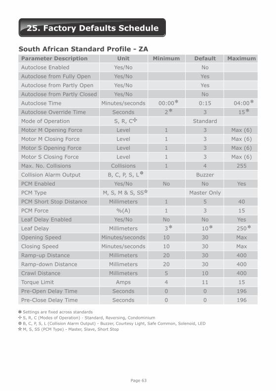
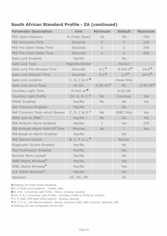
25. Factory Defaults Schedule
Unit
Yes/No
Yes/No
Yes/No
Yes/No
Minutes/seconds
Seconds
S, R, C
Level
Level
Level
Level
Collisions
B, C, P, S, L
Yes/No
M, S, M & S, SS
Millimeters
%(A)
Yes/No
Millimeters
Minutes/seconds
Minutes/seconds
Millimeters
Millimeters
Millimeters
Amps
Seconds
Seconds
Default
No
Yes
Yes
No
0:15
3
Standard
3
3
3
3
4
Buzzer
No
Master Only
5
3
No
10
30
30
30
30
10
11
0
0
Maximum
04:00
15
Max (6)
Max (6)
Max (6)
Max (6)
255
Yes
40
15
Yes
250
Max
Max
400
400
400
15
196
196
Minimum
00:00
2
1
1
1
1
1
No
1
1
No
3
10
10
20
20
5
4
0
0
Parameter Description
Autoclose Enabled
Autoclose from Fully Open
Autoclose from Partly Open
Autoclose from Partly Closed
Autoclose Time
Autoclose Override Time
Mode of Operation
Motor M Opening Force
Motor M Closing Force
Motor S Opening Force
Motor S Closing Force
Max. No. Collisions
Collision Alarm Output
PCM Enabled
PCM Type
PCM Short Stop Distance
PCM Force
Leaf Delay Enabled
Leaf Delay
Opening Speed
Closing Speed
Ramp-up Distance
Ramp-down Distance
Crawl Distance
Torque Limit
Pre-Open Delay Time
Pre-Close Delay Time
South African Standard Profile - ZA
Settings are fixed across standards
S, R, C (Modes of Operation) - Standard, Reversing, Condominium
B, C, P, S, L (Collision Alarm Output) - Buzzer, Courtesy Light, Safe Common, Solenoid, LED
M, S, SS (PCM Type) - Master, Slave, Short Stop
Page 64
Unit
% (Fully Open)
Seconds
Seconds
Seconds
Yes/No
Magnetic/Striker
Seconds
Seconds
C, O, C & O
AC,DC
H:mm:ss
Crt, A, B, C
Yes/No
Yes/No
C, O, C & O
Yes/No
Yes/No
Minutes
Yes/No
B, C, P, S, L
Yes/No
Yes/No
Yes/No
Yes/No
Yes/No
Yes/No
VC, VX, VN
Default
30
5
2
0
No
Striker
0.024.0
1.0
Close Only
AC
0:02:00
Courtesy
No
No
IRBC Only
No
Yes
1
No
Buzzer
No
Yes
No
Yes
Yes
Yes
VC
Maximum
100
240
240
240
24.0
24.0
9:59:59
Yes
Yes
Yes
Yes
225
Yes
Minimum
10
0
0
0
0.1
0.1
0:00:04
No
No
No
No
1
No
Parameter Description
PED Open Distance
PED Autoclose Time
PED Pre-Open Delay Time
PED Pre-Close Delay Time
Gate Lock Enabled
Gate Lock Type
Gate Lock Pre-Release Time
Gate Lock Release Time
Gate Lock Location
Gate Lock Drive Type
Courtesy Light Time
Courtesy Light Profile
PIRAC Enabled
SAF Common Enabled
SAF Common Tests which Beams
IRBO acts as IRBC
IRB Ambush Alarm Enabled
IRB Ambush Alarm Hold-Off Time
IRB Break-In Alarm Enabled
IRB Alarms Output
Diagnostic Screen Enabled
Test Pushbutton Enabled
Remote Menu Locked
IRBO Starts irelessW
IRBC Starts Wireless
LCK Starts Wireless
Operator
South African Standard Profile - ZA (continued)
Settings are fixed across standards
C, O (Gate Lock Location) - Closed, open
H, mm, s (Courtesy Light Time) - Hours, minutes, seconds
Crt, A, B, C (Courtesy Light Profile) - Courtesy, Profile A, Profile B, Profile C
C, O (SAF COM tests which beams) - Closing, opening
B, C, P, S, L (IR Alarms Output) - Buzzer, Courtesy Light, Safe Common, Solenoid, LED
Settings are not configurable via the GUI
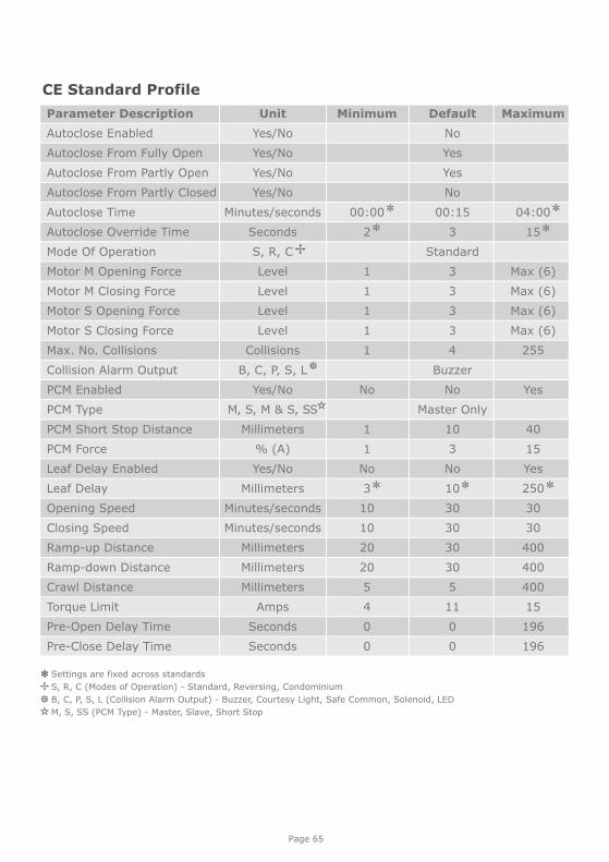
Page 65
Unit
Yes/No
Yes/No
Yes/No
Yes/No
Minutes/seconds
Seconds
S, R, C
Level
Level
Level
Level
Collisions
B, C, P, S, L
Yes/No
M, S, M & S, SS
Millimeters
% (A)
Yes/No
Millimeters
Minutes/seconds
Minutes/seconds
Millimeters
Millimeters
Millimeters
Amps
Seconds
Seconds
Default
No
Yes
Yes
No
00:15
3
Standard
3
3
3
3
4
Buzzer
No
Master Only
10
3
No
10
30
30
30
30
5
11
0
0
Maximum
04:00
15
Max (6)
Max (6)
Max (6)
Max (6)
255
Yes
40
15
Yes
250
30
30
400
400
400
15
196
196
Minimum
00:00
2
1
1
1
1
1
No
1
1
No
3
10
10
20
20
5
4
0
0
Parameter Description
Autoclose Enabled
Autoclose From Fully Open
Autoclose From Partly Open
Autoclose From Partly Closed
Autoclose Time
Autoclose Override Time
Mode Of Operation
Motor M Opening Force
Motor M Closing Force
Motor S Opening Force
Motor S Closing Force
Max. No. Collisions
Collision Alarm Output
PCM Enabled
PCM Type
PCM Short Stop Distance
PCM Force
Leaf Delay Enabled
Leaf Delay
Opening Speed
Closing Speed
Ramp-up Distance
Ramp-down Distance
Crawl Distance
Torque Limit
Pre-Open Delay Time
Pre-Close Delay Time
CE Standard Profile
Settings are fixed across standards
S, R, C (Modes of Operation) - Standard, Reversing, Condominium
B, C, P, S, L (Collision Alarm Output) - Buzzer, Courtesy Light, Safe Common, Solenoid, LED
M, S, SS (PCM Type) - Master, Slave, Short Stop
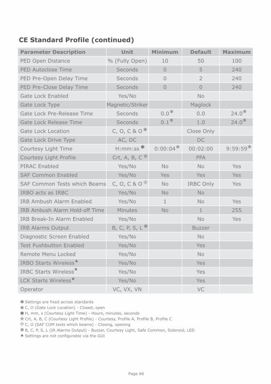
Page 66
CE Standard Profile (continued)
Unit
% (Fully Open)
Seconds
Seconds
Seconds
Yes/No
Magnetic/Striker
Seconds
Seconds
C, O, C & O
AC, DC
H:mm:ss
Crt, A, B, C
Yes/No
Yes/No
C, O, C & O
Yes/No
Yes/No
Minutes
Yes/No
B, C, P, S, L
Yes/No
Yes/No
Yes/No
Yes/No
Yes/No
Yes/No
VC, VX, VN
Default
50
5
2
0
No
Maglock
0.0
1.0
Close Only
DC
00:02:00
PFA
No
Yes
IRBC Only
No
No
1
No
Buzzer
No
Yes
No
Yes
Yes
Yes
VC
Maximum
100
240
240
240
24.0
24.0
9:59:59
Yes
Yes
Yes
Yes
255
Yes
Minimum
10
0
0
0
0.0
0.1
0:00:04
No
Yes
No
No
1
No
Parameter Description
PED Open Distance
PED Autoclose Time
PED Pre-Open Delay Time
PED Pre-Close Delay Time
Gate Lock Enabled
Gate Lock Type
Gate Lock Pre-Release Time
Gate Lock Release Time
Gate Lock Location
Gate Lock Drive Type
Courtesy Light Time
Courtesy Light Profile
PIRAC Enabled
SAF Common Enabled
SAF Common Tests which Beams
IRBO acts as IRBC
IRB Ambush Alarm Enabled
IRB Ambush Alarm Hold-off Time
IRB Break-In Alarm Enabled
IRB Alarms Output
Diagnostic Screen Enabled
Test Pushbutton Enabled
Remote Menu Locked
IRBO Starts Wireless
IRBC Starts Wireless
LCK Starts Wireless
Operator
Settings are fixed across standards
C, O (Gate Lock Location) - Closed, open
H, mm, s (Courtesy Light Time) - Hours, minutes, seconds
Crt, A, B, C (Courtesy Light Profile) - Courtesy, Profile A, Profile B, Profile C
C, O (SAF COM tests which beams) - Closing, opening
B, C, P, S, L (IR Alarms Output) - Buzzer, Courtesy Light, Safe Common, Solenoid, LED
Settings are not configurable via the GUI
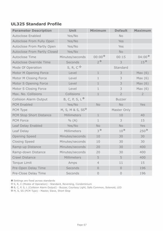
Unit
Yes/No
Yes/No
Yes/No
Yes/No
Minutes/seconds
Seconds
S, R, C
Level
Level
Level
Level
Collisions
B, C, P, S, L
Yes/No
M, S, M & S, SS
Millimeters
% (A)
Yes/No
Millimeters
Minutes/seconds
Minutes/seconds
Minutes/seconds
Minutes/seconds
Millimeters
Amps
Seconds
Seconds
Default
No
Yes
Yes
No
00:15
3
Standard
3
3
3
3
2
Buzzer
No
Master Only
10
3
No
10
30
30
30
30
5
11
0
0
Maximum
04:00
15
Max (6)
Max (6)
Max (6)
Max (6)
2
Yes
40
15
Yes
250
30
30
400
400
400
15
196
196
Minimum
00:00
2
1
1
1
1
1
No
1
1
No
3
10
10
20
20
5
4
0
0
Parameter Description
Autoclose Enabled
Autoclose From Fully Open
Autoclose From Partly Open
Autoclose From Partly Closed
Autoclose Time
Autoclose Override Time
Mode Of Operation
Motor M Opening Force
Motor M Closing Force
Motor S Opening Force
Motor S Closing Force
Max. No. Collisions
Collision Alarm Output
PCM Enabled
PCM Type
PCM Stop Short Distance
PCM Force
Leaf Delay Enabled
Leaf Delay
Opening Speed
Closing Speed
Ramp-up Distance
Ramp-down Distance
Crawl Distance
Torque Limit
Pre-Open Delay Time
Pre-Close Delay Time
UL325 Standard Profile
Page 67
Settings are fixed across standards
S, R, C (Modes of Operation) - Standard, Reversing, Condominium
B, C, P, S, L (Collision Alarm Output) - Buzzer, Courtesy Light, Safe Common, Solenoid, LED
M, S, SS (PCM Type) - Master, Slave, Short Stop
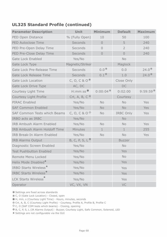
UL325 Standard Profile (continued)
Unit
% (Fully Open)
Seconds
Seconds
Seconds
Yes/No
Magnetic/Striker
Seconds
Seconds
C, O, C & O
AC, DC
H:mm:ss
Crt, A, B, C
Yes/No
Yes/No
C, O, C & O
Yes/No
Yes/No
Minutes
Yes/No
B, C, P, S, L
Yes/No
Yes/No
Yes/No
Yes/No
Yes/No
Yes/No
Yes/No
VC, VX, VN
Default
50
5
2
0
No
Maglock
0.0
1.0
Close Only
DC
0:02:00
Courtesy
No
No
IRBC Only
No
No
1
No
Buzzer
No
Yes
No
Yes
Yes
Yes
Yes
VC
Maximum
100
240
240
240
24.0
24.0
9:59:59
Yes
Yes
Yes
Yes
255
Yes
Minimum
10
0
0
0
0.0
0.1
0:00:04
No
No
No
No
1
No
Parameter Description
PED Open Distance
PED Autoclose Time
PED Pre-Open Delay Time
PED Pre-Close Delay Time
Gate Lock Enabled
Gate Lock Type
Gate Lock Pre-Release Time
Gate Lock Release Time
Gate Lock Location
Gate Lock Drive Type
Courtesy Light Time
Courtesy Light Profile
PIRAC Enabled
SAF Common Enabled
SAF Common Tests which Beams
IRBO acts as IRBC
IRB Ambush Alarm Enabled
IRB Ambush Alarm Holdoff Time
IRB Break-In Alarm Enabled
IRB Alarms Output
Diagnostic Screen Enabled
Test Pushbutton Enabled
Remote Menu Locked
Helix Mode Disabled
IRBO Starts Wireless
IRBC Starts Wireless
LCK Starts Wireless
Operator
Page 68
Settings are fixed across standards
C, O (Gate Lock Location) - Closed, open
H, mm, s (Courtesy Light Time) - Hours, minutes, seconds
Crt, A, B, C (Courtesy Light Profile) - Courtesy, Profile A, Profile B, Profile C
C, O (SAF COM tests which beams) - Closing, opening
B, C, P, S, L (IR Alarms Output) - Buzzer, Courtesy Light, Safe Common, Solenoid, LED
Settings are not configurable via the GUI
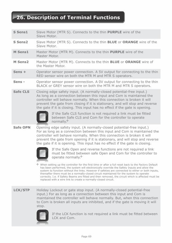
S Sens1 Slave Motor (MTR S). Connects to the thin PURPLE wire of the Slave Motor.
S Sens2 Slave Motor (MTR S). Connects to the thin BLUE or ORANGE wire of the Slave Motor.
M Sens1 Master Motor (MTR M). Connects to the thin PURPLE wire of the Master Motor.
M Sens2 Master Motor (MTR M). Connects to the thin BLUE or ORANGE wire of the Master Motor.
Sens + Operator sensor power connection. A 5V output for connecting to the thin RED sensor wire on both the MTR M and MTR S operators.
Sens - Operator sensor power connection. A 0V output for connecting to the thin BLACK or GREY sensor wire on both the MTR M and MTR S operators.
Safe CLS Closing edge safety input. (A normally-closed potential-free input.) As long as a connection between this input and Com is maintained the controller will behave normally. When this connection is broken it will prevent the gate from closing if it is stationary, and will stop and reverse the gate if it is closing. This input has no effect if the gate is opening.
If the Safe CLS function is not required a link must be fitted between Safe CLS and Com for the controller to operate normally.
Safe OPN Opening edge safety input. (A normally-closed potential-free input.) For as long as a connection between this input and Com is maintained the controller will behave normally. When this connection is broken it will prevent the gate from opening if it is stationary, and will stop and reverse the gate if it is opening. This input has no effect if the gate is closing.
If the Safe Open and reverse functions are not required a link must be fitted between safe Open and Com for the controller to operate normally.
26. Description of Terminal Functions
Page 69
LCK/STP Holiday Lockout or gate stop input. (A normally-closed potential-free input.) For as long as a connection between this input and Com is maintained the controller will behave normally. But, when this connection to Com is broken all inputs are inhibited, and if the gate is moving it will stop.
If the LCK function is not required a link must be fitted between LCK and Com.
When setting up the controller for the first time or after a full reset back to the Factory Default has been performed, the system will electronically override the Safety Inputs and allow the system to function without the links. However if safeties are connected to either or both inputs, thereafter there must be a normally-closed circuit maintained for the system to operate correctly. I.e. if Safety Beams are fitted and then removed, the circuit which is affected must be replaced with a wire link to create a normally-closed circuit.
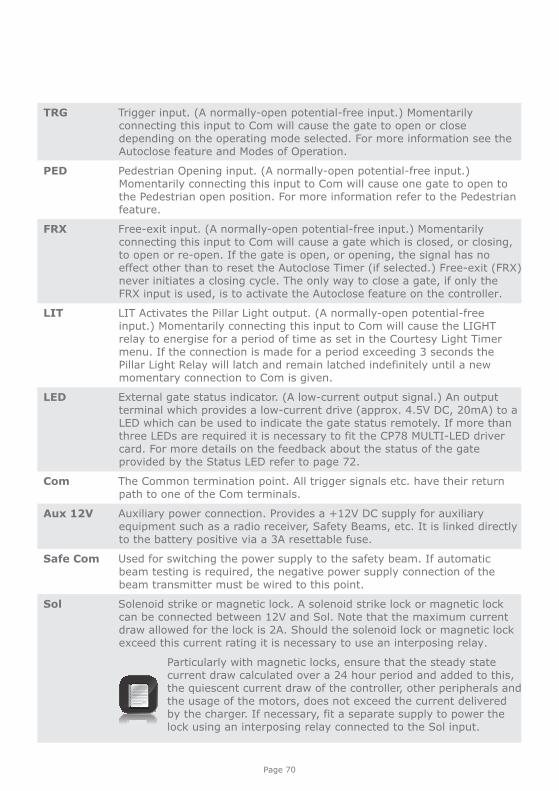
TRG Trigger input. (A normally-open potential-free input.) Momentarily connecting this input to Com will cause the gate to open or close depending on the operating mode selected. For more information see the Autoclose feature and Modes of Operation.
PED Pedestrian Opening input. (A normally-open potential-free input.) Momentarily connecting this input to Com will cause one gate to open to the Pedestrian open position. For more information refer to the Pedestrian feature.
FRX Free-exit input. (A normally-open potential-free input.) Momentarily connecting this input to Com will cause a gate which is closed, or closing, to open or re-open. If the gate is open, or opening, the signal has no effect other than to reset the Autoclose Timer (if selected.) Free-exit (FRX) never initiates a closing cycle. The only way to close a gate, if only the FRX input is used, is to activate the Autoclose feature on the controller.
LIT LIT Activates the Pillar Light output. (A normally-open potential-free input.) Momentarily connecting this input to Com will cause the LIGHT relay to energise for a period of time as set in the Courtesy Light Timer menu. If the connection is made for a period exceeding 3 seconds the Pillar Light Relay will latch and remain latched indefinitely until a new momentary connection to Com is given.
LED External gate status indicator. (A low-current output signal.) An output terminal which provides a low-current drive (approx. 4.5V DC, 20mA) to a LED which can be used to indicate the gate status remotely. If more than three LEDs are required it is necessary to fit the CP78 MULTI-LED driver card. For more details on the feedback about the status of the gate provided by the Status LED refer to page 72.
Com The Common termination point. All trigger signals etc. have their return path to one of the Com terminals.
Aux 12V Auxiliary power connection. Provides a +12V DC supply for auxiliary equipment such as a radio receiver, Safety Beams, etc. It is linked directly to the battery positive via a 3A resettable fuse.
Safe Com Used for switching the power supply to the safety beam. If automatic beam testing is required, the negative power supply connection of the beam transmitter must be wired to this point.
Sol Solenoid strike or magnetic lock. A solenoid strike lock or magnetic lock can be connected between 12V and Sol. Note that the maximum current draw allowed for the lock is 2A. Should the solenoid lock or magnetic lock exceed this current rating it is necessary to use an interposing relay.
Particularly with magnetic locks, ensure that the steady state current draw calculated over a 24 hour period and added to this, the quiescent current draw of the controller, other peripherals and the usage of the motors, does not exceed the current delivered by the charger. If necessary, fit a separate supply to power the lock using an interposing relay connected to the Sol input.
Page 70
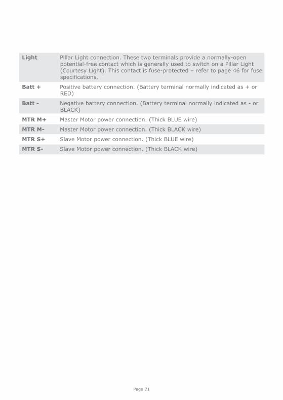
Light Pillar Light connection. These two terminals provide a normally-open potential-free contact which is generally used to switch on a Pillar Light (Courtesy Light). This contact is fuse-protected – refer to page 46 for fuse specifications.
Batt + Positive battery connection. (Battery terminal normally indicated as + or RED)
Batt - Negative battery connection. (Battery terminal normally indicated as - or BLACK)
MTR M+ Master Motor power connection. (Thick BLUE wire)
MTR M- Master Motor power connection. (Thick BLACK wire)
MTR S+ Slave Motor power connection. (Thick BLUE wire)
MTR S- Slave Motor power connection. (Thick BLACK wire)
Page 71
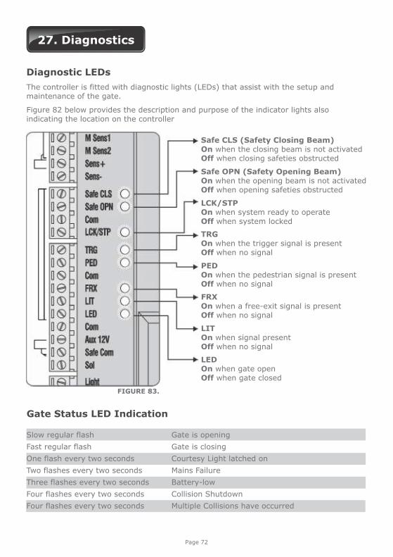
27. Diagnostics
Diagnostic LEDs
The controller is fitted with diagnostic lights (LEDs) that assist with the setup and maintenance of the gate.
Figure 82 below provides the description and purpose of the indicator lights also indicating the location on the controller
Slow regular flash Gate is opening
Fast regular flash Gate is closing
One flash every two seconds Courtesy Light latched on
Two flashes every two seconds Mains Failure
Three flashes every two seconds Battery-low
Four flashes every two seconds Collision Shutdown
Four flashes every two seconds Multiple Collisions have occurred
Gate Status LED Indication
Safe CLS (Safety Closing Beam)On when the closing beam is not activatedOff when closing safeties obstructed
Safe OPN (Safety Opening Beam)On when the opening beam is not activatedOff when opening safeties obstructed
LCK/STPOn when system ready to operateOff when system locked
TRGOn when the trigger signal is presentOff when no signal
PEDOn when the pedestrian signal is presentOff when no signal
FRXOn when a free-exit signal is presentOff when no signal
LIT On when signal presentOff when no signal
LEDOn when gate openOff when gate closed
FIGURE 83.
Page 72
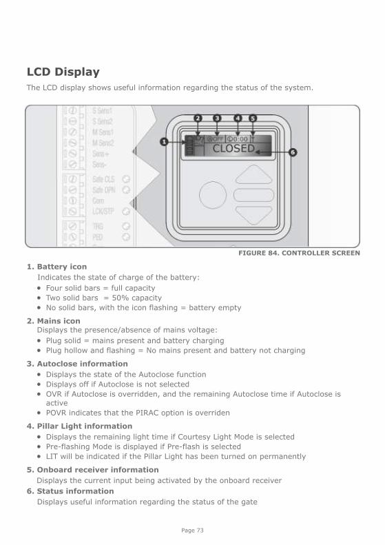
1. Battery icon
Indicates the state of charge of the battery:
Four solid bars = full capacity Two solid bars = 50% capacity No solid bars, with the icon flashing = battery empty
2. Mains icon Displays the presence/absence of mains voltage:
Plug solid = mains present and battery charging Plug hollow and flashing = No mains present and battery not charging
3. Autoclose information
Displays the state of the Autoclose function Displays off if Autoclose is not selected OVR if Autoclose is overridden, and the remaining Autoclose time if Autoclose is
active POVR indicates that the PIRAC option is overriden
4. Pillar Light information
Displays the remaining light time if Courtesy Light Mode is selected Pre-flashing Mode is displayed if Pre-flash is selected LIT will be indicated if the Pillar Light has been turned on permanently
5. Onboard receiver information
Displays the current input being activated by the onboard receiver
6. Status information
Displays useful information regarding the status of the gate
LCD Display
The LCD display shows useful information regarding the status of the system.
FIGURE 84. CONTROLLER SCREEN
Page 73
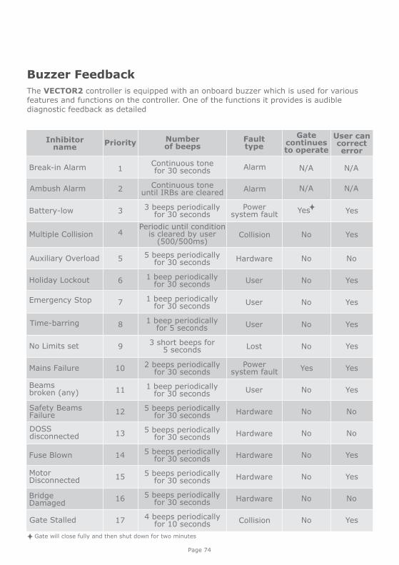
Buzzer Feedback
The VECTOR2 controller is equipped with an onboard buzzer which is used for various features and functions on the controller. One of the functions it provides is audible diagnostic feedback as detailed
Page 74
Inhibitor name
Break-in Alarm
Ambush Alarm
Auxiliary Overload
Holiday Lockout
Emergency Stop
No Limits set
Mains Failure
Beamsbroken (any)
Safety BeamsFailure
Fuse Blown
MotorDisconnected
Bridge Damaged
Gate Stalled
Multiple Collision
Battery-low
Number of beeps
Continuous tone for 30 seconds
Continuous tone until IRBs are cleared
5 beeps periodicallyfor 30 seconds
1 beep periodicallyfor 30 seconds
1 beep periodicallyfor 30 seconds
3 short beeps for5 seconds
2 beeps periodically for 30 seconds
1 beep periodically for 30 seconds
5 beeps periodically for 30 seconds
5 beeps periodically for 30 seconds
5 beeps periodically for 30 seconds
5 beeps periodically for 30 seconds
4 beeps periodically for 10 seconds
Periodic until conditionis cleared by user
(500/500ms)
3 beeps periodically for 30 seconds
Priority
1
2
5
6
7
9
10
11
12
14
15
16
17
4
3
Faulttype
Alarm
Alarm
Hardware
User
User
Lost
Power system fault
User
Hardware
Hardware
Hardware
Hardware
Collision
Collision
Power system fault
Gatecontinuesto operate
N/A
N/A
No
No
No
No
Yes
No
No
No
No
No
No
No
User can correct error
N/A
N/A
Yes
Yes
No
Yes
Yes
Yes
Yes
Yes
No
Yes
Yes
No
Yes
Gate will close fully and then shut down for two minutes
DOSS disconnected
5 beeps periodically for 30 seconds13 Hardware No No
Time-barring 1 beep periodicallyfor 5 seconds8 User No Yes
Yes

28. Installation Handover
Once the installation has been successfully completed and tested, it is important for the installer to explain the operation and safety requirements of the system.
NEVER ASSUME THE USER KNOWS HOW TO SAFELY OPERATE AN AUTOMATED GATE!
Even if the user has used one before, it does not mean he knows how to SAFELY operate it. Make sure that the user fully understands the following safety requirements before finally handing over the site.
The following needs to be understood by the user:
How to operate the manual release mechanism. (Show them how by demonstration) How the obstruction detection and all other safety features work. (Show them how
by demonstration) All the features and benefits of the operator, i.e. Beams, etc. All the safety considerations associated with operating an automated gate.
The user should be able to pass this knowledge on to all other users of the automated system and must be made aware of this responsibility.
Do not activate the gate operator unless you can see it and can determine that its area of travel is clear of people, pets, or other obstructions
NO ONE MAY CROSS THE PATH OF A MOVING GATE. Always keep people and objects away from the gate and its
area of travel
NEVER LET CHILDREN OPERATE OR PLAY WITH THE GATE CONTROLS, and do not allow children or pets near the gate area
Be careful with moving parts and avoid close proximity to areas where fingers or hands could be pinched
Secure all easily-accessed gate operator controls in order to prevent unauthorised use of the gate
Keep the automated gate system properly maintained, and ensure that all working areas are free of debris and other objects that could affect the gate operation and safety
On a monthly basis, check the obstruction detection system and safety devices for correct operation
All repair and service work to this product must be done by a suitably qualified person
This product was designed and built strictly for the use indicated in this documentation. Any other use, not expressly indicated here, could compromise the good condition/operation of the product and/or be a source of danger!
Centurion Systems (Pty) Ltd does not accept any liability caused by improper use of the product, or for use other than that for which the automated system was designed.
Ensure that the customer is in possession of the User Guide and that you have completed the installation details in the back of the User Guide.
Page 75

Notes

Notes

0.07.A.0012_19052014
www.CentSys.com
Subscribe to the newsletter: www.CentSys.com/Subscribe
facebook.com/CenturionSystems
YouTube.com/CenturionSystems
Sharecall 0860-CENTURION (0860 236 887)Head Office: +27 11 699 2400
Sharecall Technical Support 0861 003 123 or +27 11 699 2481from 07h00 to 18h00 (GMT+2)
(Sharecall numbers applicable when dialed from within South Africa only)


![New Page 1-37 [portals.iucn.org]](https://img.pdfslide.us/doc/110x75/6197be6712666b0b5f501b8b/new-page-1-37-.jpg)