Embed Size (px)
Citation preview
ISSN (Online) : 2319 - 8753 ISSN (Print) : 2347 - 6710
International Journal of Innovative Research in Science, Engineering and Technology
Volume 3, Special Issue 3, March 2014
2014 International Conference on Innovations in Engineering and Technology (ICIET’14)
On 21st & 22nd March Organized by
K.L.N. College of Engineering, Madurai, Tamil Nadu, India
Copyright to IJIRSET www.ijirset.com 53
M.R. Thansekhar and N. Balaji (Eds.): ICIET‟14
ABSTRACT—In the recent days DFIG has been the
most favorite option for wind power harnessing. Most
research in the area of wind power generation system is
based upon the control and performance improvement of
the DFIG as a generator in variable speed wind energy
systems. The slow and complex dynamics of the DFIG
makes it a challenging task for high performance control
structures. In this paper a DFIG based variable speed wind
energy system is considered. A hysteresis current
controller based stator flux oriented vector control scheme
is implemented for the high performance control of the
system. The control scheme relies upon two conventional
PI controllers and three hysteresis band current controllers
for the control purpose. The system is evaluated under
different types of disturbances and the results are
produced in this paper.
KEYWORDS— Doubly-fed induction generator, Rotor-
side vector control, P- I controller.
I. NOMENCLATURE
P: Number poles of induction motor,
e : Synchronous speed,
r : Electrical speed (rotor),
m : Mechanical rotor speed,
mL : Mutual inductance,
sL : Stator leakage inductance,
rL : Rotor leakage inductance,
sR : Stator resistance,
rR : Rotor resistance,
eT : Electromagnetic torque,
lT : Load torque,
qsI : Stator current in synchronous frame on q-axis,
dsI : Stator current in synchronous frame on d-axis,
drI : Rotor current in synchronous frame on d-axis,
qrI : Rotor current in synchronous frame on q-axis,
qsV : Stator voltage in synchronous frame on q-axis,
dsV : Stator voltage in synchronous frame on d-axis,
qrV : Rotor voltage in synchronous frame on q-axis,
drV : Rotor voltage in synchronous frame on d-axis.
P,Q : Active and reactive power.
II. INTRODUCTION
Induction machines have served well as generators in
wind energy conversion system for a long period of time.
Initially for fixed speed wind energy conversion systems
squirrel cage induction machines were employed as
power generator for their rugged design, maintenance
free performance and greater efficiency. But with the
development of variable speed wind energy conversion
systems the choice of generator has shifted towards
doubly fed induction machines. Doubly fed induction
machines inherit all the advantages of a cage induction
generator but the fact due to which they are more popular
are that the stator of the DFIG is connected directly to the
grid and it supplies power from the stator side at grid
voltage and frequency[1][2]. Other than that the control
is done from the rotor side. So the power converters used
for DFIG control are of less power rating, which reduces
the cost as well as the switching losses, which results in
enhanced efficiency. Further the doubly fed induction
A Hysteresis Band Based Vector Control of
DFIG for Wind Energy Conversion
Applications Swagat Pati#1
, Abinash Panda#2
, Sumit Sen Behera#3
#1
Department of Electrical Engineering, Siksha „O‟ Anusandhan University, Bhubaneswar, Odisha, India. #2
Department of Electrical Engineering, Siksha „O‟ Anusandhan University, Bhubaneswar, Odisha, India. #3
Department of Electrical Engineering, Siksha „O‟ Anusandhan University, Bhubaneswar, Odisha, India.
A Hysteresis Band Based Vector Control of DFIG for Wind Energy Conversion Applications
Copyright to IJIRSET www.ijirset.com 54
M.R. Thansekhar and N. Balaji (Eds.): ICIET‟14
machines can work in the generation mode both above
and below synchronous speed [2].these advantages of
DFIG sets an efficient and flexible platform for variable
speed wind power generation. The major drawback of
DFIG as a generator is slow response due to coupling of
active and reactive power. This drawback can also be
compensated by use of advance control strategies.
Different type of control schemes have been proposed for
the control of DFIGs. Among them direct torque control
[2], direct power control [2] and vector control [9]
strategies are the most frequently used control schemes.
Direct torque control is a simple strategy but as it involves
hysteresis band flux and torque controllers it suffers from
greater torque ripples [11]. But vector control scheme on
the other hand is decoupled control scheme which enables
independent control of active and reactive power [4]. So
the control becomes faster and precise. In this paper a
DFIG based wind energy conversion system is studied.
The major highlight remains on the control of rotor side
convertor for the improvement of the transient and steady
state performance of DFIG. In this work a stator flux
oriented vector control strategy is implemented for the
control of the rotor side by directional converter. The
vector control process employs conventional PI
controllers. The control strategy generates PWM
switching signals through a current regulated PWM
scheme, which consists of three hysteresis band
controllers. The whole system is modelled and simulated
in MATLAB/Simulink environment and the results are
analyzed.
III. DOUBLY FED INDUCTION GENERATOR
MODELLING
Modelling of an induction machine in three phase reference is quiet a complex and tedious task. So to reduce the complexity the machine model is converted from 3 phase to 2 phase synchronously rotating reference frame [1]. The modified voltage equations for the rotor and stator on the synchronously rotating reference frame are as follows:-
4 )()(
3 )()(
2 )(
1 )(
drreqrqrrqr
qrredrdrrdr
dseqsqssqs
qsedssdsds
dt
dIRV
dt
dIRV
dt
dIRV
dt
dIRV
The flux linkages in synchronous rotating frame can be
expressed as
8
7
6
5
qsmqrrqr
dsmdrrdr
qrmqssqs
drmdssds
ILIL
ILIL
ILIL
ILIL
The electromagnetic torque of the Induction motor is
given as:
9 22
3qrdsdrqsme IIIIL
pT
And the torque balance equation of the motor is
10 mmle Bdt
dJTT
(11) qsqsdsds iViVP
(12) qsdsdsqs iViVQ
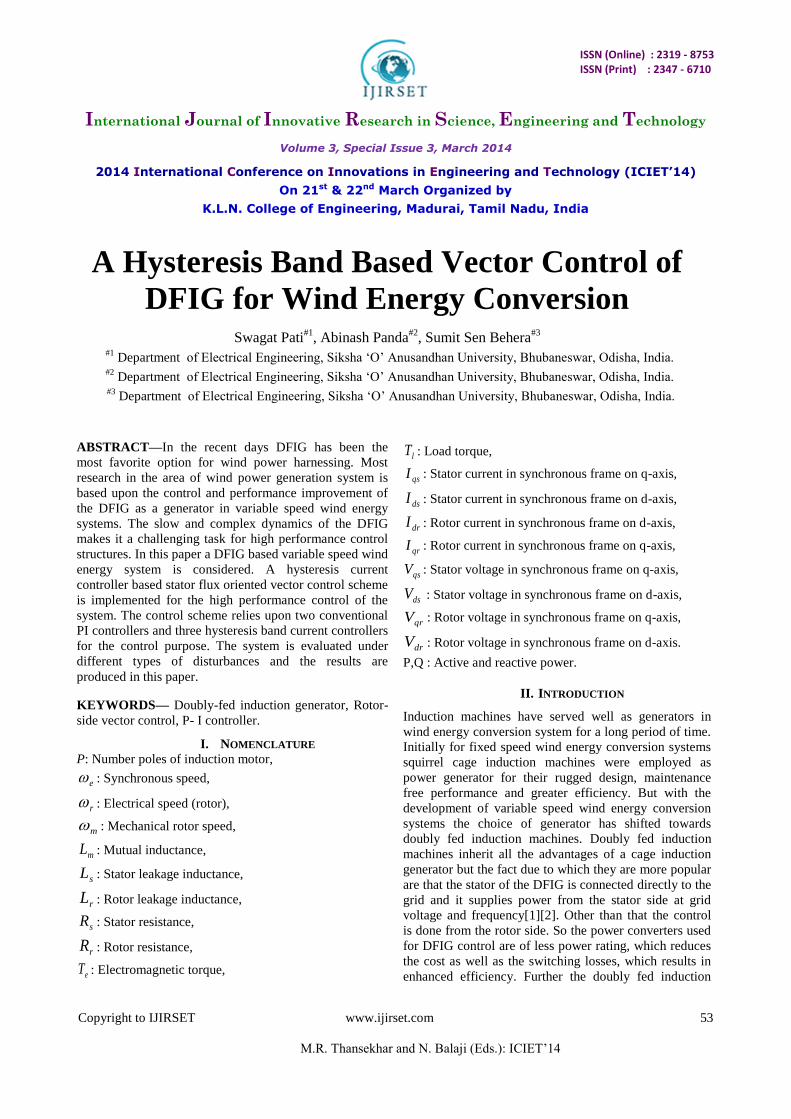
IV. INVERTER MODEL
The PWM bidirectional inverter can supply power at
variable frequency and voltage as well.[6] The equations
required for modelling of the VSI can be written as
follows
(15) ]2[6
(14) ]2[6
(13) ]2[6
bacdc
cs
cabdc
bs
cbadc
as
mmmV
V
mmmV
V
mmmV
V
Where:
asV , bsV and csV are the phase voltages
T1 to T6: switching states of the six switches, which can
either be 1, if the switch is on or 0, if the switch
is off.
dcV : DC supply voltage
am : 2T1-1,
bm : 2T3-1,
cm : 2T5-1.
A Hysteresis Band Based Vector Control of DFIG for Wind Energy Conversion Applications
Copyright to IJIRSET www.ijirset.com 55
M.R. Thansekhar and N. Balaji (Eds.): ICIET‟14
Fig. 1 Inverter Model
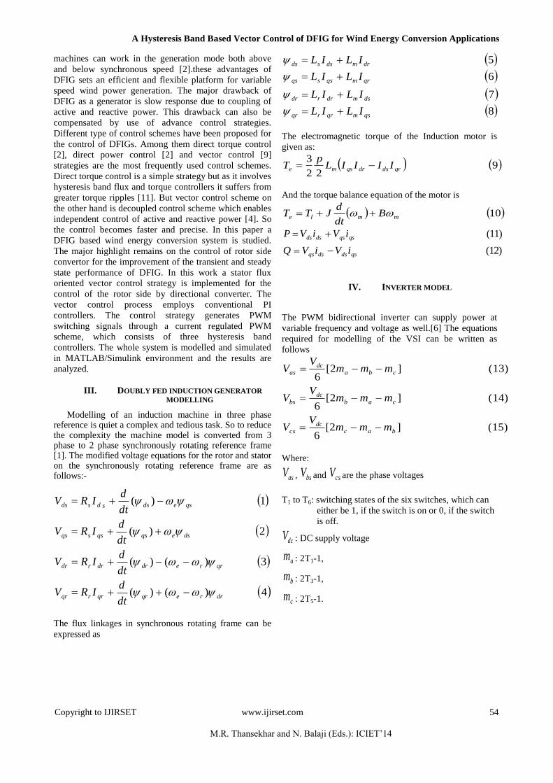
V. CONTROL STRUCTRUE
This DFIG control scheme is a rotor side control scheme
where the reactive power is controlled by the direct
current axis loop and the active power is controlled by the
quadrature current axis loop. In the active power control
loop the speed is compared with reference speed and the
error is fed to a conventional PI controller to generate the
reference quadrature axis current. Similarly the stator side
reactive power is calculated and is compared with the
reference of reactive power and the error is fed to another
PI controller to generate the reference direct axis current.
Then both the direct and quadrature axis reference
currents are converted to 2 phase deq
e to 3 phase ac
quantities the PWM generation structure considered here
is current regulated PWM (CRPWM) [6]. In this PWM
structure the 3 phase reference current are compared with
the 3 phase actual current and the errors fed to 3
hysteresis band controllers. The band widths of the
controllers are set at 5% of the rated current values. The
hysteresis controller output gives the PWM switching
pulses for the rotor side bidirectional converter control.
The whole control scheme can be referred from Fig. (2).
VI. PI CONTROLLER DESIGN
The output signal of a PI controller can be obtained by
the equation given below
(16) *** dteKeKU IP
Where „e‟ is the error signal. KP, KI the proportional gain
and integral gain respectively. Here the gain values of the
controller are tuned manually to obtain a near optimum
result.
ACTIVE POWERREACTIVE POWER
OSL CALCULATION
PI
PI
2Φ
3Φ
HY
ST
ER
ES
IS
LOO
P
CO
NT
RO
LLE
R
SPEED SENSOR
PSQS
θSL
RSCGSC
ωr
ωr
ωr*
+-- +
ω
ω
QS
QS*
iqr*
idr*
iar iar*
+--+
-
+ibr
ibr*
icricr
*
θSL
iabcr
Fig. 2.Block diagram of DFIG control structure.
A Hysteresis Band Based Vector Control of DFIG for Wind Energy Conversion Applications
Copyright to IJIRSET www.ijirset.com 56
M.R. Thansekhar and N. Balaji (Eds.): ICIET‟14
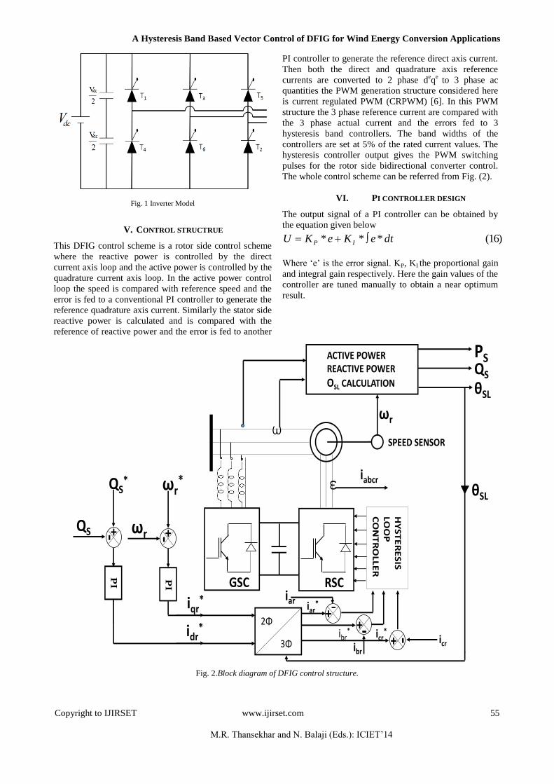
VII. HYSTERESIS BAND CONTROL DESIGN
The hysteresis band controller is described by the
following equation
If e>HB
If e<HB (17)
Where „HB‟ is the hysteresis band width, which is taken
to be 0.1 Amp. in this paper. The working of hysteresis
band can be seen from the Fig. 4. When the error exceeds
the value HB then the output of the controller becomes „1‟
and when the value of error less than –HB the output
becomes „-1‟
Fig. 4 Hysteresis band diagram
VIII. SIMULATION RESULT
The DFIG control structure was modelled and simulated
in Matlab Simulink. The simulation results obtained by
the steps given below
Step change in reference speed command.
Step change in load torque.
Step change in rotor reactive power
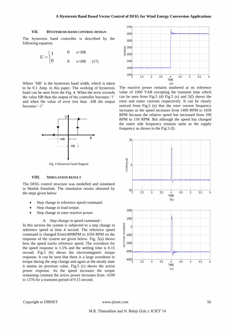
A. Step change in speed command:-
In this section the system is subjected to a step change in
reference speed at time 4 second. The reference speed
command is changed from1400RPM to 1650 RPM on the
response of the system are given below. Fig. 5(a) shows
how the speed tracks reference speed. The overshoot for
the speed response is 1.5% and the settling time is 0.15
second. Fig.5 (b) shows the electromagnetic torque
response. It can be seen that there is a large overshoot in
torque during the step change and again at the steady state
it attains its previous value. Fig.5 (c) shows the active
power response. As the speed increases the torque
remaining constant the active power increases from -3100
to 1376 for a transient period of 0.15 second.
2 2.5 3 3.5 4 4.5 5 5.5 61350
1400
1450
1500
1550
1600
1650
1700
TIME
SP
EE
D
(a)
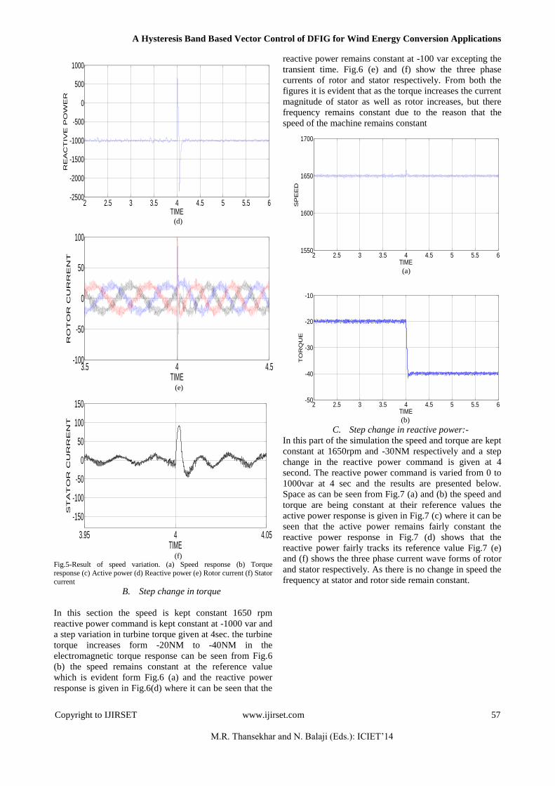
The reactive power remains unaltered at its reference
value of 1000 VAR excepting the transient time which
can be seen from Fig.5 (d) Fig.5 (e) and 5(f) shows the
rotor and stator currents respectively. It can be clearly
noticed from Fig.5 (e) that the rotor current frequency
increases as the speed increases from 1400 RPM to 1650
RPM because the relative speed has increased from 100
RPM to 150 RPM. But although the speed has changed
the stator side frequency remains same as the supply
frequency as shown in the Fig.5 (f).
2 2.5 3 3.5 4 4.5 5 5.5 6-50
0
50
TIME
TO
RQ
UE
(b)
2 2.5 3 3.5 4 4.5 5 5.5 6-4000
-3000
-2000
-1000
0
1000
2000
TIME
AC
TIV
E P
OW
ER
(c)
0
1U
A Hysteresis Band Based Vector Control of DFIG for Wind Energy Conversion Applications
Copyright to IJIRSET www.ijirset.com 57
M.R. Thansekhar and N. Balaji (Eds.): ICIET‟14
2 2.5 3 3.5 4 4.5 5 5.5 6-2500
-2000
-1500
-1000
-500
0
500
1000
TIME
RE
AC
TIV
E P
OW
ER
(d)
3.5 4 4.5-100
-50
0
50
100
TIME
RO
TO
R C
UR
RE
NT
(e)
3.95 4 4.05
-150
-100
-50
0
50
100
150
TIME
ST
AT
OR
C
UR
RE
NT
(f)
Fig.5-Result of speed variation. (a) Speed response (b) Torque
response (c) Active power (d) Reactive power (e) Rotor current (f) Stator
current
B. Step change in torque
In this section the speed is kept constant 1650 rpm
reactive power command is kept constant at -1000 var and
a step variation in turbine torque given at 4sec. the turbine
torque increases form -20NM to -40NM in the
electromagnetic torque response can be seen from Fig.6
(b) the speed remains constant at the reference value
which is evident form Fig.6 (a) and the reactive power
response is given in Fig.6(d) where it can be seen that the
reactive power remains constant at -100 var excepting the
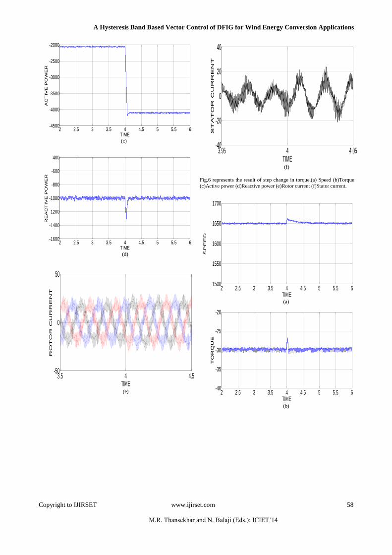
transient time. Fig.6 (e) and (f) show the three phase
currents of rotor and stator respectively. From both the
figures it is evident that as the torque increases the current
magnitude of stator as well as rotor increases, but there
frequency remains constant due to the reason that the
speed of the machine remains constant
2 2.5 3 3.5 4 4.5 5 5.5 61550
1600
1650
1700
TIME
SP
EE
D
(a)
2 2.5 3 3.5 4 4.5 5 5.5 6-50
-40
-30
-20
-10
TIME
TO
RQ
UE
(b)
C. Step change in reactive power:-
In this part of the simulation the speed and torque are kept
constant at 1650rpm and -30NM respectively and a step
change in the reactive power command is given at 4
second. The reactive power command is varied from 0 to
1000var at 4 sec and the results are presented below.
Space as can be seen from Fig.7 (a) and (b) the speed and
torque are being constant at their reference values the
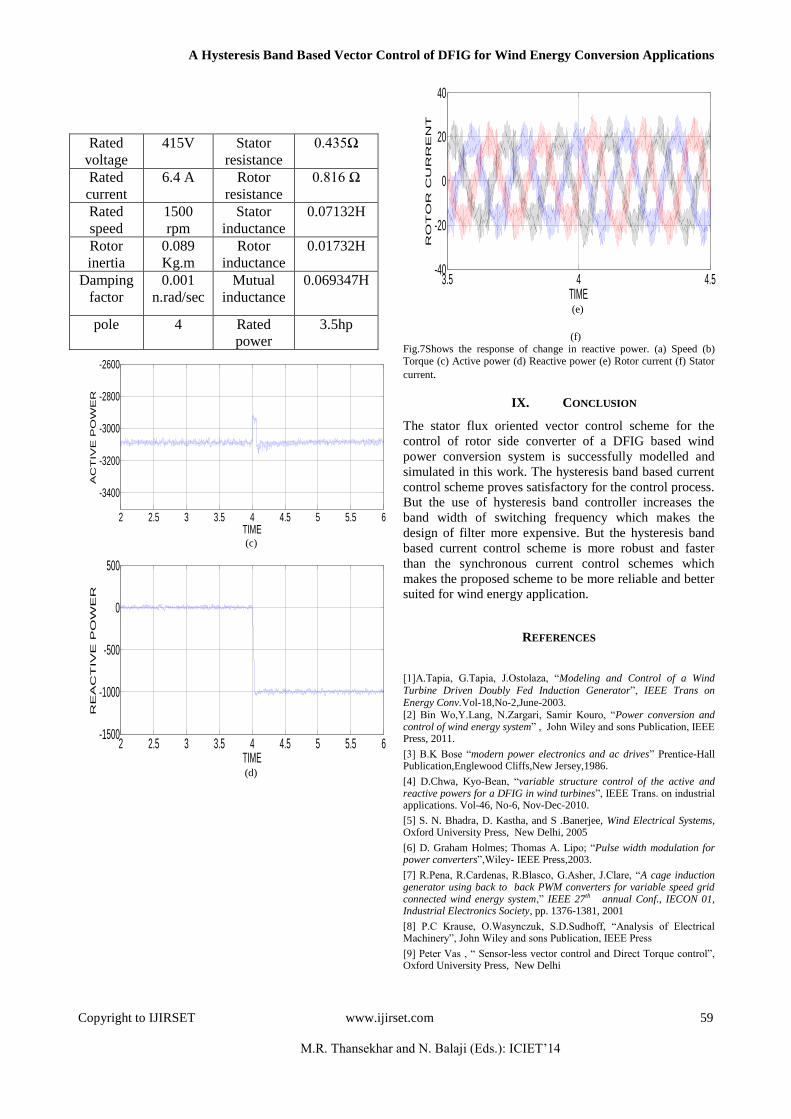
active power response is given in Fig.7 (c) where it can be
seen that the active power remains fairly constant the
reactive power response in Fig.7 (d) shows that the
reactive power fairly tracks its reference value Fig.7 (e)
and (f) shows the three phase current wave forms of rotor
and stator respectively. As there is no change in speed the
frequency at stator and rotor side remain constant.
A Hysteresis Band Based Vector Control of DFIG for Wind Energy Conversion Applications
Copyright to IJIRSET www.ijirset.com 58
M.R. Thansekhar and N. Balaji (Eds.): ICIET‟14
2 2.5 3 3.5 4 4.5 5 5.5 6-4500
-4000
-3500
-3000
-2500
-2000
TIME
AC
TIV
E P
OW
ER
(c)
2 2.5 3 3.5 4 4.5 5 5.5 6-1600
-1400
-1200
-1000
-800
-600
-400
TIME
RE
AC
TIV
E P
OW
ER
(d)
3.5 4 4.5-50
0
50
TIME
RO
TO
R C
UR
RE
NT
(e)
3.95 4 4.05-40
-20
0
20
40
TIME
ST
AT
OR
C
UR
RE
NT
(f)
Fig.6 represents the result of step change in torque.(a) Speed (b)Torque
(c)Active power (d)Reactive power (e)Rotor current (f)Stator current.
2 2.5 3 3.5 4 4.5 5 5.5 61500
1550
1600
1650
1700
TIME
SP
EE
D
(a)
2 2.5 3 3.5 4 4.5 5 5.5 6-40
-35
-30
-25
-20
TIME
TO
RQ
UE
(b)
A Hysteresis Band Based Vector Control of DFIG for Wind Energy Conversion Applications
Copyright to IJIRSET www.ijirset.com 59
M.R. Thansekhar and N. Balaji (Eds.): ICIET‟14
2 2.5 3 3.5 4 4.5 5 5.5 6
-3400
-3200
-3000
-2800
-2600
TIME
AC
TIV
E P
OW
ER
(c)
2 2.5 3 3.5 4 4.5 5 5.5 6-1500
-1000
-500
0
500
TIME
RE
AC
TIV
E P
OW
ER
(d)
3.5 4 4.5-40
-20
0
20
40
TIME
RO
TO
R C
UR
RE
NT
(e)
(f)
Fig.7Shows the response of change in reactive power. (a) Speed (b) Torque (c) Active power (d) Reactive power (e) Rotor current (f) Stator
current.
IX. CONCLUSION
The stator flux oriented vector control scheme for the
control of rotor side converter of a DFIG based wind
power conversion system is successfully modelled and
simulated in this work. The hysteresis band based current
control scheme proves satisfactory for the control process.
But the use of hysteresis band controller increases the
band width of switching frequency which makes the
design of filter more expensive. But the hysteresis band
based current control scheme is more robust and faster
than the synchronous current control schemes which
makes the proposed scheme to be more reliable and better
suited for wind energy application.
REFERENCES
[1]A.Tapia, G.Tapia, J.Ostolaza, “Modeling and Control of a Wind
Turbine Driven Doubly Fed Induction Generator”, IEEE Trans on Energy Conv.Vol-18,No-2,June-2003.
[2] Bin Wo,Y.Lang, N.Zargari, Samir Kouro, “Power conversion and control of wind energy system” , John Wiley and sons Publication, IEEE Press, 2011.
[3] B.K Bose “modern power electronics and ac drives” Prentice-Hall Publication,Englewood Cliffs,New Jersey,1986.
[4] D.Chwa, Kyo-Bean, “variable structure control of the active and reactive powers for a DFIG in wind turbines”, IEEE Trans. on industrial applications. Vol-46, No-6, Nov-Dec-2010.
[5] S. N. Bhadra, D. Kastha, and S .Banerjee, Wind Electrical Systems, Oxford University Press, New Delhi, 2005
[6] D. Graham Holmes; Thomas A. Lipo; “Pulse width modulation for power converters”,Wiley- IEEE Press,2003.
[7] R.Pena, R.Cardenas, R.Blasco, G.Asher, J.Clare, “A cage induction generator using back to back PWM converters for variable speed grid connected wind energy system,” IEEE 27th annual Conf., IECON 01, Industrial Electronics Society, pp. 1376-1381, 2001
[8] P.C Krause, O.Wasynczuk, S.D.Sudhoff, “Analysis of Electrical Machinery”, John Wiley and sons Publication, IEEE Press
[9] Peter Vas , “ Sensor-less vector control and Direct Torque control”, Oxford University Press, New Delhi
Rated
voltage
415V Stator
resistance
0.435Ω
Rated
current
6.4 A Rotor
resistance
0.816 Ω
Rated
speed
1500
rpm
Stator
inductance
0.07132H
Rotor
inertia
0.089
Kg.m
Rotor
inductance
0.01732H
Damping
factor
0.001
n.rad/sec
Mutual
inductance
0.069347H
pole 4 Rated
power
3.5hp

A Hysteresis Band Based Vector Control of DFIG for Wind Energy Conversion Applications
Copyright to IJIRSET www.ijirset.com 60
M.R. Thansekhar and N. Balaji (Eds.): ICIET‟14
[10] R. Cardenas, and R. Pena, “Sensorless vector control of induction machines for variable speed wind energy applications,” IEEE Trans. Egy.Conv., vol. 19, no. 1, pp. 196-205, Mar. 2004.
[11] Ciro Attaianese, Mauro Di Monaco, and Giuseppe Tomasso, “High Performance Digital Hysteresis Control for single source cascaded
inverter”, IEEE transactions on industrial informatics, vol. 9, no. 2, may
2013