Embed Size (px)
Citation preview
UNIVERSITY OF NIŠThe scientific journal FACTA UNIVERSITATIS
Series: Mechanics, Automatic Control and Robotics Vol.2, No 7/2, 1997 pp. 429 - 447Editor of series: Katica (Stevanovi}) Hedrih, e-mail: [email protected]
Address: Univerzitetski trg 2, 18000 Niš, YU, Tel: (018) 547-095, Fax: (018)-547-950http:// ni.ac.yu/Facta
VECTOR ANALYSIS OF THE MASS INERTIA MOMENT STATE
UDC: 531.3
Katica (Stevanović) Hedrih
18000 - Niš, Vojvode Tankosića 3/22Telefax: (381 18) 41-663
e-mail: [email protected]
Abstract. This paper introduces the vector )(NnJ of the body mass inertia moment at
the point N for the axis oriented by the unit vector n . The vector is used forinterpretation of the rigid body kinetic characteristics as well as the mass moment statein the body point. The change of the vector of the rigid body mass inertia moment isdetermined in the transition from one space point to another when the axis retains itsorientation which represents the Huygens-Steiner theorem translated for the definedbody mass inertia moment vector. Then the change of the vector of the body massinertia moment is defined at the given point in the case of the axis changing itsorientation in the way analogous to the Cauchy equations in the Elasticity theory. Thenthe interpretation of the main inertia asymmetry are defined. The relation between theaxis deviation load vector by the body mass inertia moment for the octahedron axis andthe inertia asymmetry axis is analyzed.
1. INTRODUCTIONS
The idea for this paper appeared during my considerations of some analogies betweenthe models in the stress theory and the strain theory of the stressed and straineddeformable bodies as they are studied or as they can be studied in the Elasticity Theory.See Ref.[10], [11], [26], [21], [34] and [20]. While considering this analogy as well as theanalogy between the stress tensor matrices, the relative deformation tensor-strain tensorand the body mass inertia tensor it occurred to me to introduce the concept of the vector
)(Nnδ of the total relative deformation-total relative strain, at the point N and for the line
element drawn from that point and oriented by unit vector n , as well as the concept ofthe vector )(N
nJ of the body mass inertia moment at the point N, and for the axis orientedby the unit vector n . For more details see the references [21], [34] and [20]. Received September 16, 1997
430 KATICA (STEVANOVIĆ) HEDRIH]
In further consideration of the dynamic parameters of the rigid and deformable bodiesas well as of the possibility of their interpretation by means of the vector )(N
nJ of the bodymass inertia moment at the point N for the axis oriented by the unit vector n , I came tothe ideas and conclusions as well as interpretations given in my papers [21], [34] and[20]. The question always asked was if something like that already existed in someclassic literature or not? The literature available to me which is quoted in the appendix ofthis paper contains no such interpretation of the rigid deformable bodies dynamicparameters by means of the mass inertia moment vector fixed to the point and to the axis.
This paper defines three dynamic vectors fixed to a certain point and axis passingthrough the given rigid body point. These are: the vector )(N
nM of the body mass at thepoint N for the axis oriented by the unit vector n ; the vector )(N
nS of the body mass static(linear) moment at the point N for the axis oriented by the unit vector n ; and the vector
)(NnJ of the body mass inertia moment at the point N for the axis oriented by the unit
vector n .The rigid body kinetic parameters are interpreted by these vectors.The change of the mass inertia moment vector in the transition from one rigid body
point to another is determined when the axis retains its orientation which represents themodification of the Huygens-Steiner theorem expressed by means of the defined massinertia moment vector. Then the change of the mass inertia moment vector is determinedin the case of the axis changing its orientation in the way analogous to the Cauchyequations for the total stress vector in the elasticity theory. Then the interpretation of themain inertia directions are derived as well as of the main inertia asymmetry are derived.The relation between the axis deviation load vector by the material line mass inertiamoment for the octahedron axis and the inertia asymmetry axis is analyzed.
Further interpretation of the kinetic parameters of the of the body by means of thebody mass inertia moment vector and by means of the body mass linear (static) momentvector for the axis and the point refers to the description of the motion quantity (linearmomentum) as well as motion quantity moment (angular momentum) and kinetic energyas the function of the mass moment vectors for the axis and the point and the momentaryangular velocity and referential point velocity.
2. BODY MASS MOMENTS VECTORS AT POINT FOR THE AXIS
In studying the dynamics of a rigid and solid body, geometry of mass plays animportant part. In the References [2] and [3] there is a conclusion that it is not necessaryto know all the details about the mass distribution and the masses internal structures inorder to study the rigid body translatory motion under the action of the force. Theproperties necessary for the study of the rigid body motion as a material system are therigid body dynamic properties. The values determining the dynamic properties are calledthe rigid body dynamic parameters (See Ref. [2]).
According to the given reference these parameters are taken to be: mass M of therigid body; position vector Cρ of the body mass center, the point C with respect to acertain point O and J(C) the body mass inertia moment tensor for the point C which isdetermined with six scalar dynamic parameters, In this way in the general case the
Vector Analysis of the Mass Inertia Moment State 431
dynamic rigid body characteristic ten independent scalar dynamic parameters arerequired. By means of these ten dynamic parameters of the rigid body the sixth ordermatrix of the following shape is formed:
−−
−−
−−
=
zyzxzCC
zyyxyCC
zxyxxCC
CC
CC
CC
O
xyxz
yzxy
xzyz
JDD0MMDJDM0MDDJMM0
0MMM00M0M0M0MM000M
J )( (1)
and this matrix is given in the references [2] and [3] as the rigid body mass inertia matrixfor the given point O and the given trihedron. This is the matrix of the tensor expanded inan appropriate way. The mass inertia moment matrix changes its coordinates according tothe change of the reference trihedron.
In the Reference [1] the mass linear polar moment )(M O of the material system orthe vector static system mass moment is defined with respect to the pole O in the form:
MM )(C
V
O dm ρρ∫∫∫ == (2)
where ρ is the vector of the rigid body points position with respect to the common poleO, V is the space region that the observed body occupies.
There are two important properties of a certain body mass: the mass center positionof a material body does not depend on the pole choice but only on the body massdistribution and the mass linear polar moment )(M C with respect to the body mass centeris equal to zero.
Since our aim is to consider a possibility of the interpretation of the rigid bodydynamic parameters in a modified shape we are going to set, as a reference, the pole O aswell as the axis oriented by the unit vector n . Considering that the general case the rigidbody motion can be represented by one rotation around momentary axis, that is, by thetranslation of the center velocity and the rotation around the axis through the given centerwe are led to the idea to define the rigid body dynamic parameters by means of the poleO as the referential point through we position an axis parallel to the momentary rotationaxis.
Therefore we define the following ( See Fig. No. 1a):1* Vector )(O
nM of the body mass at the point O for the axis oriented by the unitvector n :
ndmnV
On M)( ∫∫∫ ==M (3)
which does not depend on the mass distribution in the body, that is, on the density. For allthe space points and parallel axes it has the same values and it changes only with the axisorientation change. It is determined only with the mass quantity and the axis orientation.
2* Vector )(OnS of the body mass static (linear) moment at the point O for the axis
432 KATICA (STEVANOVIĆ) HEDRIH]
oriented by the unit vector n in the form:
dmnV
On ∫∫∫= ],[)( ρS (4)
where ρ is the vector of the rigid body points position of the elementary body mass dm
with respect to the common pole O. For the vector )(OnS of the body mass static (linear)
moment at the point O for the axis oriented by the unit vector n we can write:
],[],[ )()( OC
On MnMn == ρS (5)
The illustration is given in the Figure No. 1a.3* Vector )(O
nJ of he body mass inertia moment at the point O for the axis orientedby the unit vector n :
dmnV
On ∫∫∫= ]],[,[)( ρρJ (6)
It can also be considered the body mass square moment vector at the point O for theaxis, through the pole, oriented by the unit vector n . The vector )(O
nJ at the body massinertia moment at the point O for the axis oriented by the unit vector n can bedecomposed into three components: the collinear with the axis )(J o
n and the two otherones )(D O
nu and )(D Onv in the directions, u and v , normal to the orientation axis n . The
collinear component represents the axial moment of the body mass inertia for the axisoriented by the unit vector n through the pole O. The other two components representthe deviational moments of the body mass for a couple of normal axes oriented by unitvectors n and u , that is, n and v :
vun Onv
Onu
On
On
)()()()( DDJ ++=J (7)
The definition-expression for the body mass inertia moment vector )(OnJ at the point O
for the axis oriented by the unit vector n can be obtained starting from the expression forthe axial body mass inertia moment )(J o
n for the axis oriented by unit vector n drawnthrough the point O and for the deviational body mass moments for the couples of theorthogonal axes oriented by unit vectors ),( un and ),( vn , )(D O
nu and )(D Onv , according to
the Ref. [21], [34]. By means of them we form the vector )(OnJ of the body mass inertia
moment at the point O for the axis oriented by the unit vector n in the form:
dmvnvdmunudmnnVVV
On ∫∫∫∫∫∫∫∫∫ ++= ]),[],,([]),[,],([],[ 2)( ρρρρρJ (8)
The rigid body axial mass inertia moment is:
dmnV
On
2)( ],[J ∫∫∫= ρ (8*)
The rigid body mass deviation moment vector )(OnD at the point O for the axis oriented
by the unit vector n is in the following form:
Vector Analysis of the Mass Inertia Moment State 433
dmndmvnvdmunuVVV
On ∫∫∫∫∫∫∫∫∫ =+= ]),[],,T([T]),[],,([]),[],,([)( ρρρρρρD
]],[,[]]]],,[,[[,[ )()( nndmnnn On
V
On JD == ∫∫∫ ρρ (9)
By means of the previous expressions (8) for the vector )(OnJ of the body mass
inertia moment at the point O for the axis oriented by the unit vector n we canwrite the expression identical to the expression (6) which has been set as adefinition.
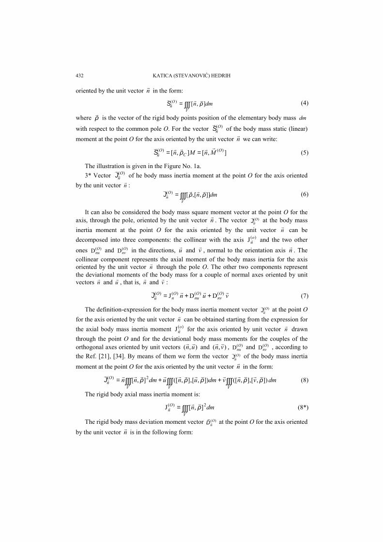
Fig. No.1a
Fig. No. 1a shows the vector )(OnJ of the body mass inertia moment at the point O for
the axis oriented by the unit vector n , the rigid body mass deviation moment vector )(OnD
at the point O for the axis oriented by the unit vector n , the axial moment of the bodymass inertia )(J o
n for the axis oriented by the unit vector n through the pole O, and theother two components, )(D O
nu and )(D Onv , the deviational moments of the body mass for a
couple of normal axes oriented by unit vectors n and u , that is, n and v , through thepole O.
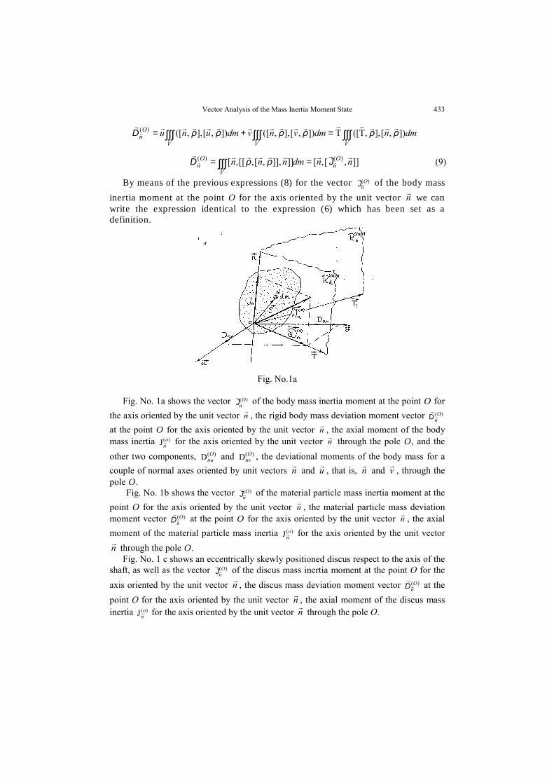
Fig. No. 1b shows the vector )(OnJ of the material particle mass inertia moment at the
point O for the axis oriented by the unit vector n , the material particle mass deviationmoment vector )(O
nD at the point O for the axis oriented by the unit vector n , the axialmoment of the material particle mass inertia )(J o
n for the axis oriented by the unit vectorn through the pole O.
Fig. No. 1 c shows an eccentrically skewly positioned discus respect to the axis of theshaft, as well as the vector )(O
nJ of the discus mass inertia moment at the point O for theaxis oriented by the unit vector n , the discus mass deviation moment vector )(O
nD at thepoint O for the axis oriented by the unit vector n , the axial moment of the discus massinertia )(J o
n for the axis oriented by the unit vector n through the pole O.
434 KATICA (STEVANOVIĆ) HEDRIH]
Fig. No.1 b Fig. No.1c
3. THE HUYGENS-STEINER THEOREM GENERALIZED TO THE MATERIAL BODY MASSINERTIA MOMENT VECTOR FOR THE AXIS THROUGH REFERENTIAL POINT
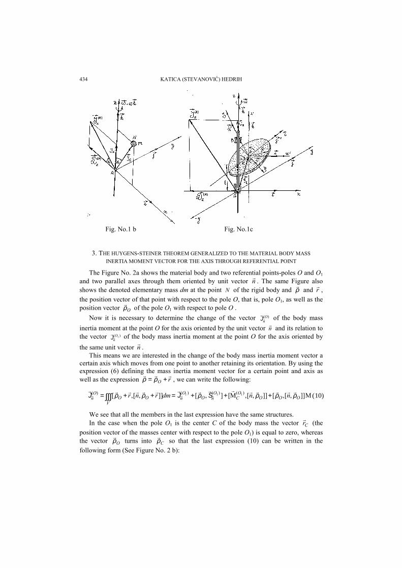
The Figure No. 2a shows the material body and two referential points-poles O and O1
and two parallel axes through them oriented by unit vector n . The same Figure alsoshows the denoted elementary mass dm at the point N of the rigid body and ρ and r ,the position vector of that point with respect to the pole O, that is, pole O1, as well as theposition vector Oρ of the pole O1 with respect to pole O .
Now it is necessary to determine the change of the vector )(OnJ of the body mass
inertia moment at the point O for the axis oriented by the unit vector n and its relation tothe vector )( 1O
nJ of the body mass inertia moment at the point O for the axis oriented bythe same unit vector n .
This means we are interested in the change of the body mass inertia moment vector acertain axis which moves from one point to another retaining its orientation. By using theexpression (6) defining the mass inertia moment vector for a certain point and axis aswell as the expression rO += ρρ , we can write the following:
M]],[,[]],[,M[],[]],[,[ )()()()( 111OOO
OC
OnO
On
VOO
On nndmrnr ρρρρρρ +++=++= ∫∫∫ SJJ (10)
We see that all the members in the last expression have the same structures.In the case when the pole O1 is the center C of the body mass the vector Cr (the
position vector of the masses center with respect to the pole O1) is equal to zero, whereasthe vector Oρ turns into Cρ so that the last expression (10) can be written in thefollowing form (See Figure No. 2 b):
Vector Analysis of the Mass Inertia Moment State 435
M]],[,[)()(CC
Cn
On n ρρ+= JJ (11)
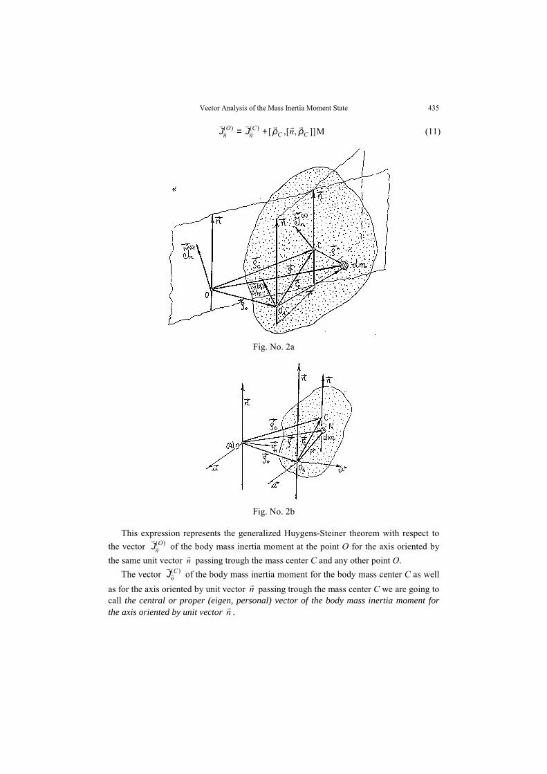
Fig. No. 2a
Fig. No. 2b
This expression represents the generalized Huygens-Steiner theorem with respect tothe vector )(O
nJ of the body mass inertia moment at the point O for the axis oriented bythe same unit vector n passing trough the mass center C and any other point O.
The vector )(CnJ of the body mass inertia moment for the body mass center C as well
as for the axis oriented by unit vector n passing trough the mass center C we are going tocall the central or proper (eigen, personal) vector of the body mass inertia moment forthe axis oriented by unit vector n .
436 KATICA (STEVANOVIĆ) HEDRIH]
The part M]],[,[)(, CCO
positionn n ρρ=J from the expression (11) represents the positionpart of the body mass inertia moment vector and we going to call it the body mass inertiaposition moment vector for the point O and the axis oriented by unit vector n in relationto the body mass center C . We can see that the body mass inertia moment vector for theaxis trough the mass center C is the "smallest" vector since for all the other parallel axesthe position part M]],[,[)(
, CCO
positionn n ρρ=J has to be taken into consideration. This canbe expressed by means of the vector )(O
nS of the body mass linear moment for the point O
and the axis oriented by unit vector n in the form ],[ )(OnC Sρ .
4. THE CHANGE OF THE BODY MASS INERTIA MOMENT VECTOR FOR THE POINTAND AXIS ORIENTATION CHANGE THROUGH THE REFERENTIAL POINT
Let's now define the vectors )(OxJ , )(O
yJ and )(OzJ of the body mass inertia moments at
the point O and for the coordinate axes Ox, Oy and Oz. These vectors can be expressed inthe form:
dmiV
Ox ∫∫∫= ]],[,[)( ρρJ dmj
V
Oy ∫∫∫= ]],[,[)( ρρJ dmk
V
Oz ∫∫∫= ]],[,[)( ρρJ (12)
If we denote the senses cosine of the unit vector n with αcos , cosβ and cosγ whenthe unit vector defines the orientation of the axis passing though the point O, then we cansuccessively multiply the expressions (12) and we obtain them added:
dmndmkjiVV
Oz
Oy
Ox ∫∫∫∫∫∫ =++=++ ]],[,[],coscoscos[,[coscoscos )()()( ρρργβαργβα JJJ
From the previous expression we conclude that the body mass inertia moment vector)(O
nJ at the point O for the axis oriented by the unit vector n is equal to:
γβα coscoscos )()()()( Oz
Oy
Ox
On JJJJ ++= (13)
The last expression is analogous to the equation for determining the total stress vector)(O
np at the point O of the stressed body for the plane with normal unit vector n which isknown as the Cauchy equation in the elasticity theory. There fore we are going to call itthe Cauchy equation giving the relation of the body mass inertia moment vector )(O
nJ at
the point O for the axis oriented by the unit vector n and the vectors )(OxJ , )(O
yJ and )(OzJ
of the body mass inertia moments at the point O and for the coordinate axes Ox, Oy andOz.
5. CAUCHY EQUATIONS IN THE MATRIX FORM
Now by means of the mass inertia moment tensor matrix J(O) the Cauchy vectorequation (13) can be written in the matrix form:
Vector Analysis of the Mass Inertia Moment State 437
}{}}){}{}{({}{ )()()()()( nn OOz
Oy
Ox
On J== JJJJ (14)
Now for the body mass axial inertia moment )(J On for the axis oriented by the unit
vector n , as well as for the body mass deviation moment we can write by means of themass inertia moment )(D O
vn for the orthogonal axes n and v we can write the followingexpressions:
}{)(}){(J )()()( nnn OOn
On J== J , }{)(}){(D )()()( nvv OO
nOvn J== J (15)
The invariants of the body mass inertia moment state at a certain point can bedetermined as the first )(
1J O , second )(1J O and third )(
1J O scalar of the body mass inertiamoment tensor matrix.
The rigid body mass inertia moment tensor matrix )(J O for a certain pole can beseparated into two matrices corresponding to the spherical sphO)(J and deviational
devOdevO )()( DJ = part of the rigid body mass inertia moment tensor (which is analogousto the stress tensor matrix and strain (relative deformation) tensor matrix in the elasticitytheory):
=
=
)(1
)(1
)(1
)(1
)(
J3100
0J310
00J31
100010001
J31
O
O
O
OsphOJ (16)
IJ31})}{}{({ )(
1)()()()()()( OO
vO
uO
nsphOOdevO −=−= JJJJJJ (17)
6. AXIAL AND DEVIATIONAL PART OF THE RIGID BODY MASS INERTIA MOMENT VECTOR
The body mass inertia moment vector )(OnJ at the point O for the axis oriented by the
unit vector n can be written in the transformed form in which we separate the part aksOn
)(J
collinear with axis oriented by unit vector n and the part devOn
On
)()( JD = normal to the axisoriented by unit vector n as it is shown in the Figure No. 1a and No. 3.
Now the vector )(OnJ of the rigid body mass inertia moment at the point O for the axis
oriented by the unit vector n can be transformed to the following form:)()()()()()()( ]],[,[),( O
naksO
nO
nO
ndevO
naksO
nO
n nnnn DJJJJJJ +=+=+= (18)with components:
)()()( J),( On
On
aksOn nnn == JJ (19)
]],[,[ )()()( nn On
devOn
On JJD == (20)
438 KATICA (STEVANOVIĆ) HEDRIH]
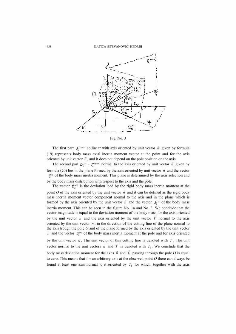
Fig. No. 3
The first part aksOn
)(J collinear with axis oriented by unit vector n given by formula(19) represents body mass axial inertia moment vector at the point and for the axisoriented by unit vector n , and it does not depend on the pole position on the axis.
The second part devOn
On
)()( JD = normal to the axis oriented by unit vector n given byformula (20) lies in the plane formed by the axis oriented by unit vector n and the vector
)(OnJ of the body mass inertia moment. This plane is determined by the axis selection and
by the body mass distribution with respect to the axis and the pole.The vector )(O
nD is the deviation load by the rigid body mass inertia moment at thepoint O of the axis oriented by the unit vector n and it can be defined as the rigid bodymass inertia moment vector component normal to the axis and in the plane which isformed by the axis oriented by the unit vector n and the vector )(O
nJ of the body massinertia moment. This can be seen in the figure No. 1a and No. 3. We conclude that thevector magnitude is equal to the deviation moment of the body mass for the axis orientedby the unit vector n and the axis oriented by the unit vector T normal to the axisoriented by the unit vector n , in the direction of the cutting line of the plane normal tothe axis trough the pole O and of the plane formed by the axis oriented by the unit vectorn and the vector )(O
nJ of the body mass inertia moment at the pole and for axis oriented
by the unit vector n . The unit vector of this cutting line is denoted with T . The unitvector normal to the unit vectors n and T is denoted with 1T . We conclude that the
body mass deviation moment for the axes n and 1T passing through the pole O is equalto zero. This means that for an arbitrary axis at the observed point O there can always befound at least one axis normal to it oriented by 1T for which, together with the axis
Vector Analysis of the Mass Inertia Moment State 439
oriented by the unit vector n , the body mass deviation moment is equal to zero. This axisis normal to the axis oriented by the unit vector n and to the deviation plane formed bythe unite vector n and the vector )(O
nJ of the body mass inertia moment at the pole O andfor axis oriented by the unit vector n . The deviaton plane we denote by Rd. Only for themass inertia moment main axis through a retain point-pole the deviation plane is notdefined nor it can be said it exists since if the axis oriented by the unit vector n through acertain point is the main axis of the body mass inertia moment then for this axis thedeviation load to the axis is equal to zero. In this case the body mass inertia momentvector has only one component collinear with the axis. That is, if a certain axis through acertain point-pole is the main mass inertia moment than the vector of its deviation load bythe body mass inertia moment is equal to zero.
7. SPHERICAL AND DEVIATORIAL PART OF THE RIGID BODY MASS MOMENT VECTOR
If we now follow the idea of the formation of matrices of the spherical and deviatorialpart of the inertia tensor according to the analogy (See Ref. [21], [20] and [34]) with thespherical and deviatorial part of the stress tensor, that is, of the relative deformation(strain) tensor we can define two vectors (See Figure No.3):
sphOn
)(J the vector spherical part of the vector )(OnJ of the rigid body mass inertia
moment at the pole O and for axis oriented by the unit vector n :
nn OO
OsphOn
)()(1
)( J31J
31 ==J (21)
DOn
)(J the vector deviatoriall part of the vector )(OnJ of the rigid body mass inertia
moment at the pole O and for axis oriented by the unit vector n :
)()(1
)()()(1
)()( J31),(]],[,[
31),( O
nOO
nO
nOO
nDO
n nnnnnnn DJJJJJ +−=+−= (22)
Let's now consider the modification of the Huygens-Steiner theorem in its applicationto the vector )()( O
ndevO
n DJ = the deviation part of the vector )(OnJ of the rigid body mass
inertia moment at the pole O and for axis oriented by the unit vector n , as well as thevector of the deviation load by the rigid body mass inertia moment on the axis orientedby the unit vector n in the transition from the mass center C to the pole O (See FigureNo. 2 b). We use the definition of the vector )(O
nD of the deviation load by the massinertia moment (18) and the formula (11) derived in the paragraph for the Huygens-Steiner formula of the vector )(O
nJ of the rigid body mass inertia moment at the pole O
and for axis oriented by the unit vector n so that:
M]],[,)[,(]],[,[ )()()()( nnnnn CCC
nO
nO
ndevO
n ρρ−=== DJDJ (23)
The expression (23) represents the Huygens-Steiner Theorem modified to the vector)(O
nD of the deviation load by the mass inertia moment of the axis oriented by the vector
440 KATICA (STEVANOVIĆ) HEDRIH]
n connected to the pole O. From this expression we conclude that the vector )(OnD of the
axis deviational load through an arbitrary point O oriented by the unit vector n equal tothe sum of the vector )(C
nD of the axis deviation load through the center C of the bodymass for the parallel axis and the position deviation load in the transition of the axis fromthe pole C - mass center to the pole- arbitrary point O determined from the expression:
[ ][ ][ ][ ] [ ][ ]M,,),(M,,,)( nnnnnn CCCCOC
n ρρρρ −==→D (24)
If the pole O and the center C of the body mass are located on the same normal to theaxis oriented by the unit vector n then the position part of the deviation load in thetransition from the axis through the mass center C to the parallel axis through the pole Ois equal to zero. This means that the deviation load vectors of the axis by the body massinertia moment for the central plane points corresponding to the given axis are equal tothe deviation load belonging to the central axis )(C
nD .
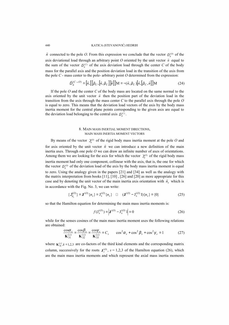
8. MAIN MASS INERTIAL MOMENT DIRECTIONS,MAIN MASS INERTIA MOMENT VECTORS
By means of the vector )(OnJ of the rigid body mass inertia moment at the pole O and
for axis oriented by the unit vector n we can introduce a new definition of the maininertia axes. Through one pole O we can draw an infinite number of axes of orientations.Among them we are looking for the axis for which the vector )(O
nJ of the rigid body massinertia moment had only one component, collinear with the axis, that is, the one for whichthe vector )(O
nD of the deviation load of the axis by the body mass inertia moment is equalto zero. Using the analogy given in the papers [21] and [34] as well as the analogy withthe matrix interpretation from books [11], [10] , [26] and [20] as more appropriate for thiscase and by denoting the unit vector of the main inertia axis orientation with sn which isin accordance with the Fig. No. 3, we can write:
}{J}{}{ )(s
)()(s
Os
OOn nn
s== JJ ⇒ }0{}I){J( )(
s)( =− s
OO nJ (25)
so that the Hamilton equation for determining the main mass inertia moments is:
0IJ)(J )(s
)()(s =−= OOOf J (26)
while for the senses cosines of the main mass inertia moment axes the following relationsare obtained:
sss
ss
ss C=== )(
33)(
32)(
31
coscoscosKKK
γβα 1coscoscos 222 =++ sss γβα (27)
where 3,2,1,)(3 =ks
kK are co-factors of the third kind elements and the corresponding matrixcolumn, successively for the roots )(O
sJ , s = 1,2,3 of the Hamilton equation (26), whichare the main mass inertia moments and which represent the axial mass inertia moments
Vector Analysis of the Mass Inertia Moment State 441
for the main mas inertia moments axes. There are three roots and three orthogonal mainaxes at every point with respect to which the rigid mass inertia moment vectors aredetermined. The Hamilton equation coefficients are the first, second and third invariantsof the mass inertia moment state at referent point, and they are the first, second and thirdscalar of the body mass inertia moment tensor matrix at referent point (see Ref. [21] or[20]).
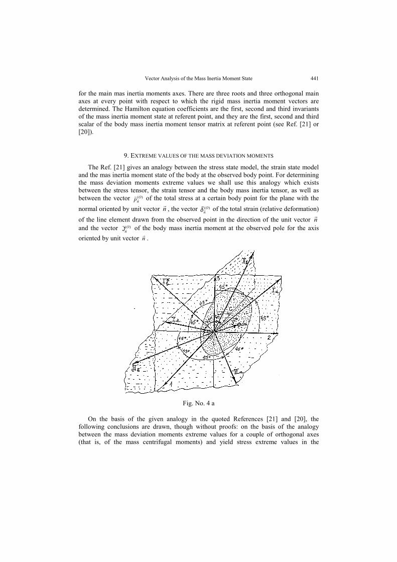
9. EXTREME VALUES OF THE MASS DEVIATION MOMENTS
The Ref. [21] gives an analogy between the stress state model, the strain state modeland the mas inertia moment state of the body at the observed body point. For determiningthe mass deviation moments extreme values we shall use this analogy which existsbetween the stress tensor, the strain tensor and the body mass inertia tensor, as well asbetween the vector )(O
np of the total stress at a certain body point for the plane with thenormal oriented by unit vector n , the vector )(O
nδ of the total strain (relative deformation)of the line element drawn from the observed point in the direction of the unit vector nand the vector )(O
nJ of the body mass inertia moment at the observed pole for the axisoriented by unit vector n .
Fig. No. 4 a
On the basis of the given analogy in the quoted References [21] and [20], thefollowing conclusions are drawn, though without proofs: on the basis of the analogybetween the mass deviation moments extreme values for a couple of orthogonal axes(that is, of the mass centrifugal moments) and yield stress extreme values in the
442 KATICA (STEVANOVIĆ) HEDRIH]
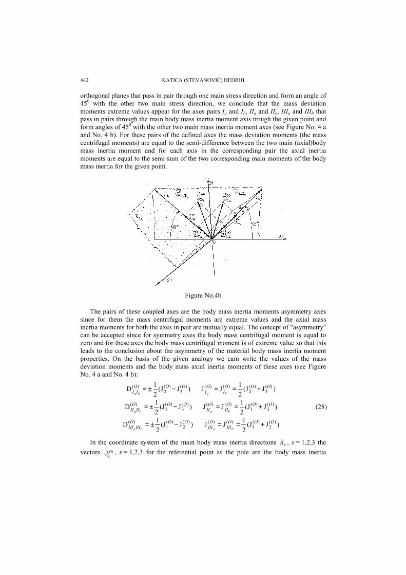
orthogonal planes that pass in pair through one main stress direction and form an angle of450 with the other two main stress direction, we conclude that the mass deviationmoments extreme values appear for the axes pairs Ia and Ib, IIa and IIb, IIIa and IIIb thatpass in pairs through the main body mass inertia moment axis trough the given point andform angles of 450 with the other two main mass inertia moment axes (see Figure No. 4 aand No. 4 b). For these pairs of the defined axes the mass deviation moments (the masscentrifugal moments) are equal to the semi-difference between the two main (axial)bodymass inertia moment and for each axis in the corresponding pair the axial inertiamoments are equal to the semi-sum of the two corresponding main moments of the bodymass inertia for the given point.
Figure No.4b
The pairs of these coupled axes are the body mass inertia moments asymmetry axessince for them the mass centrifugal moments are extreme values and the axial massinertia moments for both the axes in pair are mutually equal. The concept of "asymmetry"can be accepted since for symmetry axes the body mass centrifugal moment is equal tozero and for these axes the body mass centrifugal moment is of extreme value so that thisleads to the conclusion about the asymmetry of the material body mass inertia momentproperties. On the basis of the given analogy we cam write the values of the massdeviation moments and the body mass axial inertia moments of these axes (see FigureNo. 4 a and No. 4 b):
)J(J21D )(
3)(
2)( OOO
II ba−±= )J(J
21JJ )(
3)(
2)()( OOO
IO
I ba+==
)J(J21D )(
3)(
2)( OOOIIII ba
−±= )J(J21JJ )(
3)(
1)()( OOO
IIO
II ba+== (28)
)J(J21D )(
2)(
1)( OOOIIIIII ba
−±= )J(J21JJ )(
2)(
1)()( OOO
IIIO
III ba+==
In the coordinate system of the main body mass inertia directions sn , s = 1,2,3 thevectors )(O
nsJ , s = 1,2,3 for the referential point as the pole are the body mass inertia
Vector Analysis of the Mass Inertia Moment State 443
moment vectors for the main mass inertia moment axes and we see that they have onlythe components collinear with the corresponding main mass inertia moment axes
sO
sO
n ns
)()( J=J , s = 1,2,3.
Let's now define the vectors )(OIa
J , )(OIIa
J and )(OIIIa
J of the body mass inertia moment at
the observed point for the axis oriented by the unit vector aIn , or
aIIn or aIIIn of the
mass inertia moment asymmetry axis Ia or IIa or IIIa by using the definition of this vectorso that we have (see Figure No. 4 b):
)()()(322
2 On
On
OIa
JJJ += ; )()()(312
2 On
On
OIIa
JJJ += ; )()()(212
2 On
On
OIIIa
JJJ += (29)
Let's now define the vectors )(OIb
J , )(OIIb
J and )(OIIIb
J of the body mass inertia moment at
the observed point for the axis oriented by the unit vector bIn or
bIIn or bIIIn of the mass
inertia moment asymmetry axis Ib or IIb, or IIIb by using the definition of this vector sothat we have:
)()()(322
2 On
On
OIb
JJJ +−= ; )()()(312
2 On
On
OIIb
JJJ +−= ; )()()(212
2 On
On
OIIIb
JJJ +−= (30)
Now we define the components of the vector )(OIb
J . The collinear one with the body
mass inertia moments symmetry axis Ia :
)()()(
3)(
2)( JJ2
JJ),( O
IO
I
OO
IO
I baaan ==
+=J (31)
The component normal to the body mass inertia moment asymmetry axis lying in thedeviation plane representing the vector )(O
IaD of the deviation load by the body mass
inertia moment of the mass inertia moment asymmetry axis according to the previouslygiven definition in the form:
bbabaaaa IO
III
OO
IO
IIO
I nnnn )()(
3)(
2)()( D2
JJ]],[,[ =
−== JD (32)
Analysis the expressions from (28) to (32) we conclude the following:1* The expressions given in (28) on the analogy basis are correct;2* Both the vectors )(O
IaJ and )(O
IbJ of the rigid body mass inertia moment for the pole
O and the axis of the pair I of the mass inertia moment asymmetry, Ia and Ib are normal tothe main mass inertia moment axis (1) and they lie in the plane RIaIb which is their mutualdeviation plane. This plane is normal to the main mass inertia moment axis (1) andcontains the other two main mass inertia moment directions (2) and (3);
3* The vector )(OIa
D of the deviation load by the body mass inertia moment of the mass
inertia moment asymmetry axis oriented by unit vector aIn at given point lie in the
direction of the second mass inertia moment asymmetry axis oriented by unit vector bIn
444 KATICA (STEVANOVIĆ) HEDRIH]
of the pair I which is normal to the main mass inertia moment direction (1) and to the axisthe mass inertia moment asymmetry Ia and vice versa. These two vectors, that is,
)(OIa
D and )(OIb
D , are the same magnitude and of the same components, of axial and
deviational, and they have the same axial mass inertia moments. In a similar way thecalculation can be applied to the other two pairs of the mass inertia moment asymmetryaxes and the corresponding conclusions can be drawn in accordance with the expressions(28) and the previous conclusions.
10. MASS INERTIA MOMENT VECTORS FOR THE OCTAHEDRONDIRECTIONS IN THE REFERENTIAL POINT
In analogy with defining the octahedron directions a certain point of the stressed andstrained body as it is done in the elasticity or plasticity theory we shall define theoctahedron directions at a certain point of the rigid body form the viewpoint of the bodymass inertia moment state with respect to this pole as the direction that forms the sameangles with the main inertia axes, that is, with the main inertia directions. There are eightsuch octahedron directions.
The vector )(OoctJ of the mass inertia moment at the point O for the octahedron
direction by using the basic definition is calculated as:
)(33]],[,[ )()()()(
321
On
On
On
Voct
Ooct dmn JJJJ ++== ∫∫∫ ρρ (33)
and we can decompose it into two components.1* The axial component in the octahedron direction:
)()(1
)()( J32J
31),(J O
OOO
octoctO
n noct
=== J (34)
which represents the axial moment of the rigid body mass inertia moment for theoctahedron direction axis for the given pole and it is equal to one third of the first massinertia moment invariant or one third of the first scalar of the mass inertia polar momentfor the pole O.
2* Normal component to the octahedron direction which is equal to the vector )(OoctD of
the octahedron axis deviation load, by the body mass inertia moment and has the form:
)(9
62 )()()()( OIII
OII
OI
Ooct aaa
DDDD ++−= (35)
The vector )(OoctD of the deviation load by the body mass inertia moment of the
octahedron axis can be expressed as the linear combination of the vectors )()()( ,, OIII
OII
OI aaa
DDD
of the deviation load of the mass inertia moments asymmetry axes when it is related toone of the pair.
The intensity square of the vector )(OoctD of the deviation load by the body mass inertia
moment of the octahedron axis can be defined by the following expression:
Vector Analysis of the Mass Inertia Moment State 445
++=
2)(2)(2)(2)(
94 O
IIIO
IIO
IO
oct aaaDDDD (36)
It should be noted that there are eight axes (or four axes) at each point of the rigidbody for which the inertia axial moments are equal to a third of the first mass inertiamoment invariant and they are the octahedron directions determined with respect to themain mass inertia moment axes. The question shousld be asked about what sort of motionthe body performs while rotating around the octahedron axis and if the conclusions canbe generalized to hold for the bodies with different mass inertia moment characteristics.
If this conclusion is related to the previous section we can conclude that is: one set ofeight (or four) axes for which the axial inertia moments of the body mass are mutuallyequal and equal to a third of the first mass inertia moment invariant: Three sets of twopairs of orthogonal axes of the inertia asymmetry for the axial inertia moments are alsoequal to the semi-sum of two main inertia moments each. The same stand for each bodyand for each pole chosen within the space or outside the space of the rigid body. Only thespherical body as the pole of all fourteen axes the axial mass inertia moment is the sameand the deviation load is equal to zero.
Acknowledgment: This research was supported by Science Ministry of Serbia, grantnumber 0402A through Mathematical Institute SANU Belgrade. The author is grateful toprofessor dr Veljko Vujičić for his valuable suggestions.
REFERENCES
1. Andjelić, T. i Stojanović, R., (1965), Racionalna mehanika, Zavod za izdavanje udžbenika, Beograd. 2. Bilimović, A., (1955), Dinamika čvrstog tela, SANU, Beograd. 3. Bilimović, A., (1951), Racionalna mehanika II, Mehanika sistema, Naučna knjiga, Beograd.89. 4. Br~i}, V., (1975), Teorija konstrukcija, Gra|evinska kwiga, Beograd 5. Goldstein, H., (1980), Classical Mechanics, Addison-Wesley Publishing Company, Massachusetts. 6. Pars, L.A., (1971), Treatise on Analytical Dynamics, (in russian Language), Nauka, Moscow. 7. Rašković, D., (1972), Dinamika, Naučna knjiga, Beograd. 8. Rašković, D., (1966), Mehanika - Kinematika, Zavod za izdavanje udžbenika Srbije, Beograd. 9. Rašković, D., (1974), Analitička mehanika, Mašinski fakultet, Kragujevac. 10. Rašković, D., (1971), Osnovi matričnog računanja, Naučna knjiga, Beograd. 11. Rašković, D. (1974), Teorija elastičnosti, Naučna knjiga, Beograd. 12. Vujičić, V.A.,(1990), Dynamics of Rheonomic Systems, Math. Inst. Beograd. 13. Vujičić, V., (1962) Kretanje dinamički promenljivih objekata i njihova stabilnost, doktor. dis. Beograd. 14. Vujičić, V., (1984) O samorotaciji nebeskih tela, Jugoslovensko društvo za mehaniku,XVI Jugoslovenski
kongres Teorijske i primenjene mehanike, Bečići, A Opšta mehanika, - A1-1, 233-238. 15. Vujičić, V., (1964) O jednom pitanju obrtanja tela promenljive mase, Matematički vesnik,1 (16), sv. 2,
119-126. 16. Vujičić, V., (1987) The tensotial Equations of self-rotation of celestial bodies, Tensor, N. S., vol. 44,
96-102. 17. Wittenburg, J., (1977), Dynamics of Systems of Rigid Bodies, B.G. Tebner Stittgart. 18. Hedrih (Stevanović), K., (1992), On Some interpretations of the rigid bodies kinetic parameters, XVIII
th ICTAM HAIFA 1992, Abstracts. 19. Hedrih (Stevanović), K., (1993) Same vectorial interpretations of the kinetic parameters of solid material
lines, ZAMM. Angew.Math. Mech. 73, 4-5, T153-T156. 20. Hedrih (Stevanović), K., (1991) Zbirka rešenih zadataka iz Teorije elastičnosti sa prilozima, Naučna
knjiga, Beograd, Prilog. 21. Hedrih (Stevanović), K., (1991), Analogy between models of stress state, strain state and state of
moment inertia mass of body, Facta Universitatis, Series "Mechanics, Automatic Control and Robotics",
446 KATICA (STEVANOVIĆ) HEDRIH]
Niš, vol.1, N 1, 1991, pp. 105-120. Referisan od strane I.T.Selezova u Referativnom žurnalu, (16.Mehanika, 16V. Mehanika deformiruemogo tvrodgo tela, Vipusk svodnogo toma, N3, Moskva 1993.MethSci Disc 1993-1996, record 2 of 4, CPM 96 08, Mathematical Review)
22. Hedrih (Stevanović), K., (1995), New Interpretation of the Rigid Bodies Kinetic Parameters, Abstracts of2-nd International Symposium of Ukrainian Mechanical Engineers in Lviv, State University "LvivskaPolitechnika", Ukainian engineerr's Society in Lviv and Ukainian engineerr's Socciety of America, INC.pp. 51
23. Hedrih (Stevanović), K, (1995), Interpretation of the Motion Equations of a variable mass objectrotating around a atationary axis by means of the mass moment vector for the pole and the axis,Procedings of the 4th Greek National Congress on Mechanics, vol. 1, Mechanics of Solids, DemocritusUniversity of Thrace, Xanthi, 1995, pp 690-696.
24. Hedrih (Stevanović), K., (1995), Senzitivna zavisnost prinudnog oscilovanja /obrtanja/ haotičnogkretanja teškog tela, od početnih uslova, (Sensitive dpendence on initial conditions of forcedvibration/rotation/stochastic-like motion of a heavy body around a stationary axis, in the field withdamping), Proceedings of the YUCTAM NIŠ ' 95, Invited Letures, IL, YSM, Niš, pp. 239-253.
25. Hedrih (Stevanović) K., (1997) Nonlinear dynamics of rotor with a vibrating axis, Invited letures,Proceedings of the YUCTAM Vrnjačka Banja '97, Yugoslav Society of Mechanics, pp. 165-174.
26. Hedrih (Stevanović) Katica, (1988) Izabrana poglavlja Teorije elastičnosti, Mašinski fakultet u Nišu,prvo izdanje 1976, drugo izdanje, str. 424.
27. Rašković, D i Stevanović, K. (Hedrih), (1966-1967), Ubrzanje drugog reda (trzaj) pri obrtanju tela okonepomične tačke, Zbornik radovaTehničkog fakulteta u Nišu, 1966-1967 godina, str. 93-100.
28. Hedrih (Stevanović), K., (1991), On Rotation of a heavy Body Around a Stationary Axis in the Fiels withTurbulent Damping and Dynamic Pressures on Bearings, Abstract of lectures YUCNP Niš'91, pp. 38-39.
29. Hedrih (Stevanović), K., (1992/93), Neka razmišljanja o kinematici linijskih elemenata deformabilnogtela pri malim deformacijama, (A Contribution to the Kinematics of Line Elements of Deformable Bodieswith Small Deformations), Zbornik radova Gra|evinskog fakulteta Univerziteta u Nišu, Broj. 13-14,1992/1993, pp. 51-56.
30. Hedrih (Stevanović), K., (1992), Neke vektorske interpretacije kinetike deformabilnih tela i fluida,Zbornik radova Simpozijuma is Mehanike fluida posvećenog akademiku Konstantinu Voronjecu,Mašinski fakultet, Beograd, str. 279-286.
31. Hedrih (Stevanović), K., (1994), Interpretation of the motion of a heavy body around a stationary axis inthe field with turbulent damping and kinetic pressures on bearing by means of the mass moment vectorfor the pole and the axis, "Facta Universitatis", Series "Mechanics, Automatic Control and Robotics",Vol. 1, N4, 1994, Niš. pp. 519-538.
32. Hedrih (Stevanović), K., (1994), Vektori vezani za polove i pravu i pojmovi vektora sektorskih momenatamasa i površina za pol i osu i sektorski pol, Apstrakt, Sažeci, PRIM 94, Primenjena analiza, IX Seminarprimewene matematike, Budva, 30 maj-1 jun 1994, Novi Sad, str. 44.
33. Hedrih (Stevanović), K., (1994), Interpretation of the motion of a heavy body around a stationary axisand kinetic pressures on bearing by means of the mass moment vector for the pole and the axis,Theoretical and Applied Mechanics, N 20, 1994, pp. 69-87. Beograd, rad po pozivu Jugoslovenskogdruštva za mehaniku za jubilarni broj časopisa povodom 20 godina publikovanja časopisa i ure|ivanja,posvećen uredniku prof. dr V.Vujučiću. MethSci Disc 1993-1996, reccord 2 of 4, CPM 96 08,Mathematiccal Reviews
34. Hedrih (Stevanović), K., (1991), Analogije modela stanja napona,stanja deformacije i stanja momenatainercije mase tela, Tehnika, prihvaćeno za štampu, 1995, N 6, str. Beograd. (1995)
35. Hedrih (Stevanović), K., (1995), Energijska analiza kinetike konstrukcija za različite modele materijala,Kratki prikazi radova naučnog skupa "Mehanika, materijali i konstrukcije", Srpska Akademija Nauka iUmetnosti, Odelenje tehničkih nauka, 1995, str. 106-107.
36. Hedrih (Stevanović), K., (1995), Tenzor stanja slučajnih vibracija, (Tensor state of the randomvibrations), Zbornik radova Mašinskog fakulteta povodom 35 godina mašinstva, Mašinski fakultet, Niš,1995, str. 133-136.
37. Hedrih (Stevanović), K., (1995), O jednom kinetičkom modelu rotora centrifugalne pumpe, (Some kineticmodel of the double-flow castings pump rotor), Zbornik radova Mašinskog fakulteta povodom 35 godinemašinstva, Mašinski fakultet, Niš, 1995, str. 137-152.
38. Hedrih (Stevanović), K., (1995), Neke vektorske interpretacije kinetike fluida - II deo, (Some vectorialinterpretations of the fluid Kinetics - part II), Zbornik radova Mašinskog fakulteta povodom 35 godinemašinstva, Mašinski fakultet, Niš,1995, str. 153-165.
39. Hedrih (Stevanović), K., (1995), On New Interpretations of the rigid Bodies Kkinetic Parameters and onRotation of a Heavy body around a Stationary Axis in the Foeld with Turbulent Damping and Dynamic
Vector Analysis of the Mass Inertia Moment State 447
Pressures on Bearings, Conference on Differential Geometry and Applications, Masaryk University,Brno 1995, Zbornik Apstrakata.
40. Hedrih (Stevanović), K., (1995), On one of the kinetic models of the rotor of exchangeble mass, FactaUniversitatis, Series Mechanical Engineering, vol. 1 N. 2, 1995, pp.185-208.
41. K.(Stevanović) Hedrih, (1996) Interpretation of the Rigid Bodies Kinetics by Vectors of the Bodies MassMoments, Invited Lecture, Book of Abstracts, The International Conference: Stability, Control and RigidBodies Dynamics - ICSCD 96, Institute of Applied Mathematics & Mechanics of NAS of Ukraine,Donetsk - Mariupol, 2-6 September, pp. 35-36.(MatInst).
42. Hedrih (Stevanović), K., (1993), The mass moment vectors at n-dimensional coordinate system, Tensor,Vol 54 (1993), pp. 83-87.
43. Hedrih (Stevanović), K., (1996), Neke interpretacije kinetičkih parametara krutih tela, Tehnika, 11-12,Mašinstvo 45 (1996) 11-12, str. 8M-M13.
44. K.(Stevanović) Hedrih, (1996), Model Rotora izmenljive mase i primena na dinamiku rotora radnog kolacentrifugalne pumpe, Model of a Rotor of Exchangeable Mass and Analogous Applying to the Dynamicof Rotor of Centrifugal Pump, II International Symposium: Contemporary Problems of Fluid Mechanics,Proceedings, 30 September - 2. October, Belgrade, YSM, Faculty of Mechanical Engineering, Belgrade,1996, pp. 281-284. (MašFak).
45. K.(Stevanović) Hedrih, (1997), Nelinearna dinamika rotora sa oscilujućom osom, (Nonlinear dynamicsof rotor with a vibrating axis), Abstracts of the YUCTAM Vrnjačka Banja 97, pp.93-94.
46. Hedrih (Stevanović), K., (1997), Nonlinear Dynamics of Rotor with a vibratin axis and sensitivedependence on initial conditions of forced vibration/rotation/stochasticlike -chaotic like motion of a hevyrotor, Third Bogoliubov Readings: Asymptotic and Qualitative Methods of Nonlinear Mechanics,ASYM 97, Tezi dopovidey, Institut Math. NANU, Kiev, pp.73-74.
VEKTORSKA ANALIZA STANJAMOMENTA INERCIJE MASA
Katica (Stevanović) Hedrih
U ovom radu su uvedeni vektori momenata masa i tački N za osu orjentisanu jediničnimvektorom n . Vektori momenata masa se mogu koristiti za interpretaciju kinetičkih parametarakrutih tela i za analizu stanja momenata masa u nekoj tački tela, odnosno prostorne konfiguracijemasa u odnosu na neki pol. Za promenu vektora momenata masa krutog tela pri promeni pola izadržavanju orjentacije osa izvedena je uopštena Huygens-Steiner-ova teorema. Za promenuvektora momenata masa kasa osa kroz pol menja prvac orjentacije izvedena je vektorska jednačinakoja je analogna Cauchy-jevim jednačinama iz teorije elastičnosti. Pomoću vektora momenatamasa izvedena je analiza stanja prostorne konfiguracije masa krutog tela u odnosu na neki pol,koja omogućava određivanje glavnih pravaca momenata inercije, pravaca inercione asimetrije ioktaedarskih pravaca prostorne konfiguracije masa. Iz članka se da videti da uvođenje vektoramomenata masa omogućava očiglednu i pristupačnu analizu stanja geometrijske konfiguracijemasa tela.