Embed Size (px)
Citation preview
TUZ-03-2015-ENG
TECHNICAL INSTRUCTIONSfor authorized service CentroPelet ZV/ZVB (Centropelet ZV14-32 / ZVB 15-30)
HEATING TECHNIQUE
Centrometal d.o.o. - Glavna 12, 40306 Macinec, Hrvatska, tel: +385 40 372 600, fax: +385 40 372 61 1
MAIN COMPONENTS OF THERMOSTOVE
The stoves are equipped with the following mechanical and electrical components:
1. Fan environment (only CentroPelet ZV)The fan, located at the top of the stove, blows the hot air coming from the stove body. The fan is tangential.
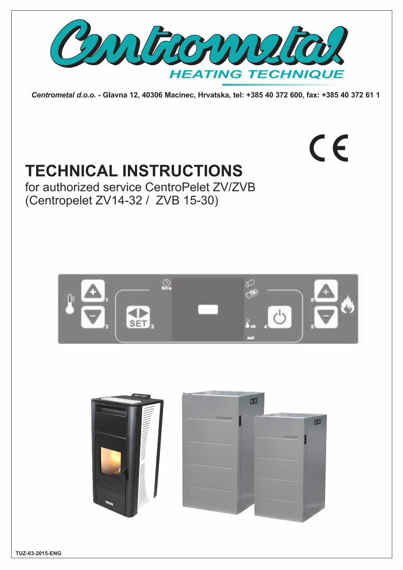
2. Ignition ResistanceResistance candle is located behind the combustion chamber, the tube ignition. The candle is designed to heat the air
that is sucked by the smoke fan.
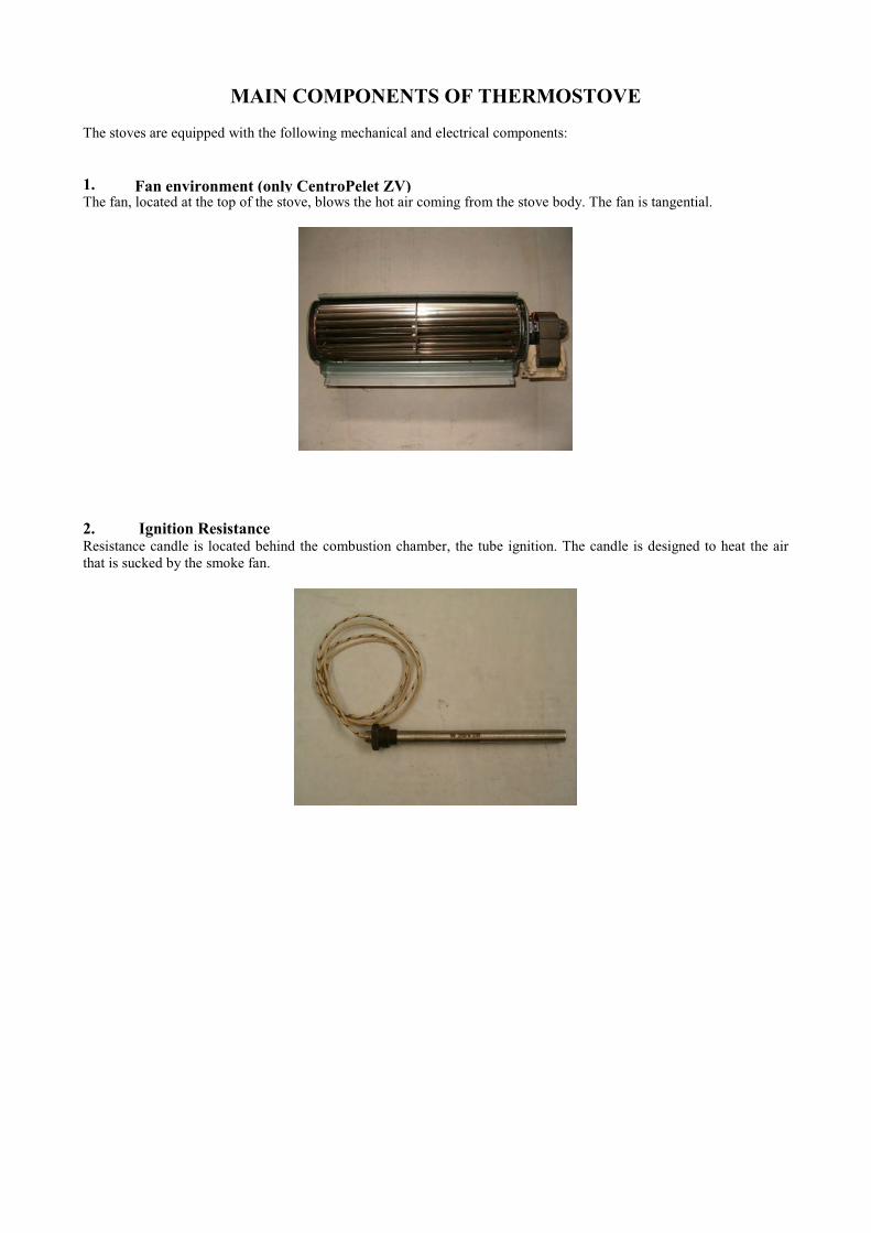
3. Room SensorProbe environment, on the back of the stove, detects the temperature in the room.
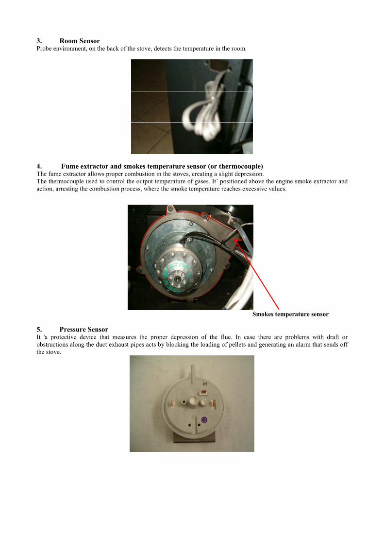
4. Fume extractor and smokes temperature sensor (or thermocouple)The fume extractor allows proper combustion in the stoves, creating a slight depression.
The thermocouple used to control the output temperature of gases. It’ positioned above the engine smoke extractor and
action, arresting the combustion process, where the smoke temperature reaches excessive values.
Smokes temperature sensor
5. Pressure SensorIt 'a protective device that measures the proper depression of the flue. In case there are problems with draft or
obstructions along the duct exhaust pipes acts by blocking the loading of pellets and generating an alarm that sends off
the stove.
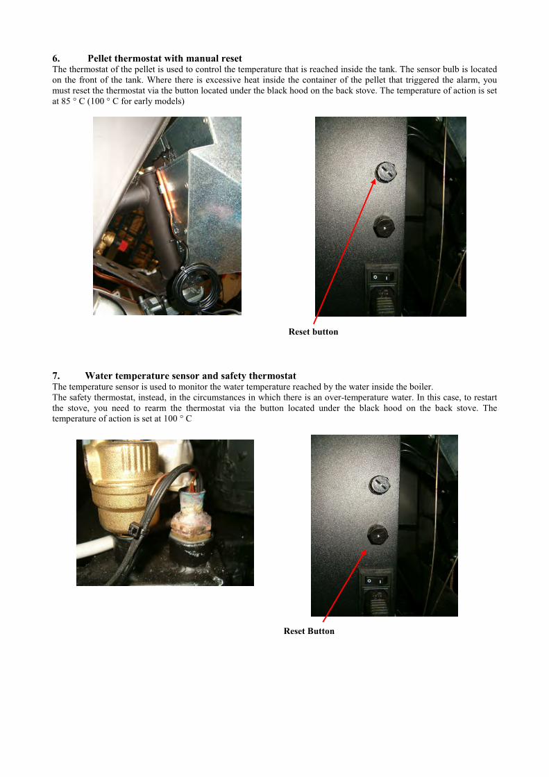
6. Pellet thermostat with manual resetThe thermostat of the pellet is used to control the temperature that is reached inside the tank. The sensor bulb is located
on the front of the tank. Where there is excessive heat inside the container of the pellet that triggered the alarm, you
must reset the thermostat via the button located under the black hood on the back stove. The temperature of action is set
at 85 ° C (100 ° C for early models)
7. Water temperature sensor and safety thermostatThe temperature sensor is used to monitor the water temperature reached by the water inside the boiler.
The safety thermostat, instead, in the circumstances in which there is an over-temperature water. In this case, to restart
the stove, you need to rearm the thermostat via the button located under the black hood on the back stove. The
temperature of action is set at 100 ° C
Reset button
Reset Button
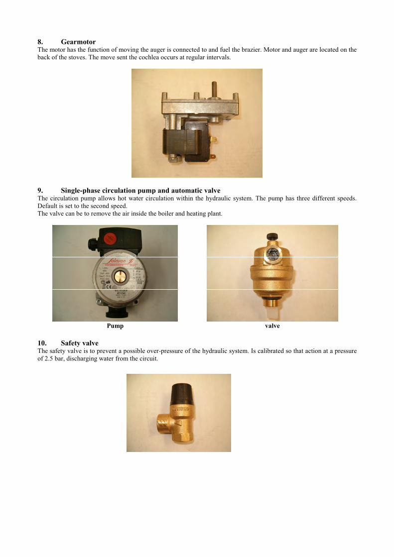
8. GearmotorThe motor has the function of moving the auger is connected to and fuel the brazier. Motor and auger are located on the
back of the stoves. The move sent the cochlea occurs at regular intervals.
9. Single-phase circulation pump and automatic valveThe circulation pump allows hot water circulation within the hydraulic system. The pump has three different speeds.
Default is set to the second speed.
The valve can be to remove the air inside the boiler and heating plant.
Pump valve
10. Safety valveThe safety valve is to prevent a possible over-pressure of the hydraulic system. Is calibrated so that action at a pressure
of 2.5 bar, discharging water from the circuit.
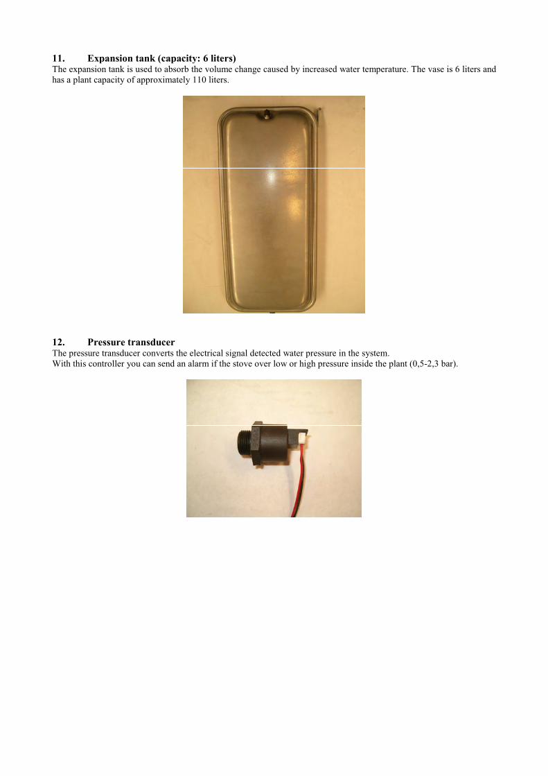
11. Expansion tank (capacity: 6 liters)The expansion tank is used to absorb the volume change caused by increased water temperature. The vase is 6 liters and
has a plant capacity of approximately 110 liters.
12. Pressure transducerThe pressure transducer converts the electrical signal detected water pressure in the system.
With this controller you can send an alarm if the stove over low or high pressure inside the plant (0,5-2,3 bar).
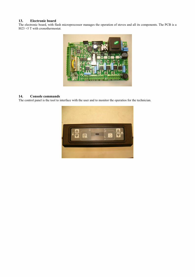
13. Electronic boardThe electronic board, with flash microprocessor manages the operation of stoves and all its components. The PCB is a
I023 +5 T with cronothermostat.
14. Console commandsThe control panel is the tool to interface with the user and to monitor the operatios for the technician.
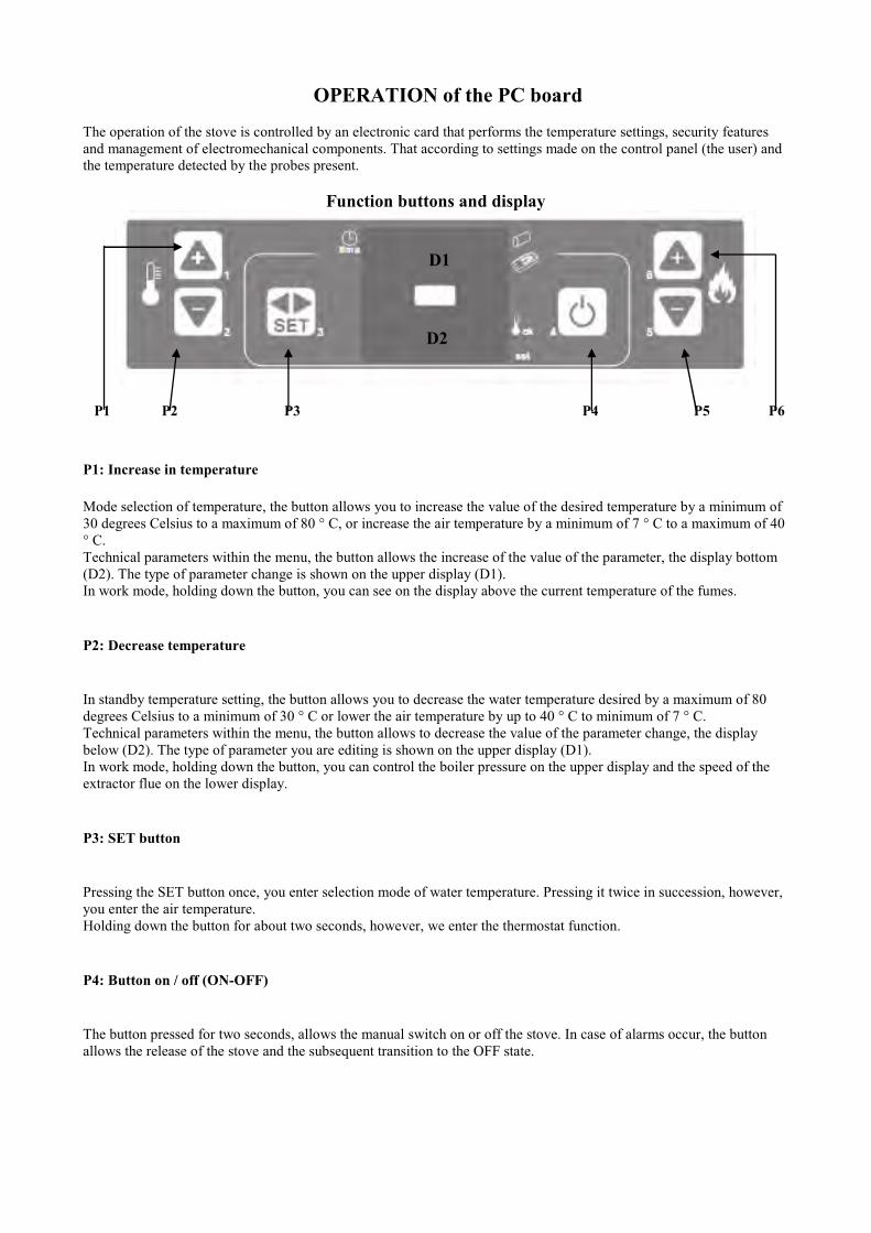
OPERATION of the PC board
The operation of the stove is controlled by an electronic card that performs the temperature settings, security features
and management of electromechanical components. That according to settings made on the control panel (the user) and
the temperature detected by the probes present.
Function buttons and display
P1 P2 P3 P4 P5 P6
P1: Increase in temperature
Mode selection of temperature, the button allows you to increase the value of the desired temperature by a minimum of
30 degrees Celsius to a maximum of 80 ° C, or increase the air temperature by a minimum of 7 ° C to a maximum of 40
° C.
Technical parameters within the menu, the button allows the increase of the value of the parameter, the display bottom
(D2). The type of parameter change is shown on the upper display (D1).
In work mode, holding down the button, you can see on the display above the current temperature of the fumes.
P2: Decrease temperature
In standby temperature setting, the button allows you to decrease the water temperature desired by a maximum of 80
degrees Celsius to a minimum of 30 ° C or lower the air temperature by up to 40 ° C to minimum of 7 ° C.
Technical parameters within the menu, the button allows to decrease the value of the parameter change, the display
below (D2). The type of parameter you are editing is shown on the upper display (D1).
In work mode, holding down the button, you can control the boiler pressure on the upper display and the speed of the
extractor flue on the lower display.
P3: SET button
Pressing the SET button once, you enter selection mode of water temperature. Pressing it twice in succession, however,
you enter the air temperature.
Holding down the button for about two seconds, however, we enter the thermostat function.
P4: Button on / off (ON-OFF)
The button pressed for two seconds, allows the manual switch on or off the stove. In case of alarms occur, the button
allows the release of the stove and the subsequent transition to the OFF state.
D1
D2

P5: Decrease caloric power Mode of work and with a temperature lower than the set temperature, the button will decrease the value of the effective
heat of the stove from a maximum of 9 to a minimum of 1.
P6: Increased caloric power In ways of working and always in the presence of a temperature lower than the set temperature, the button allows you to
increase the caloric output of the stove for a minimum of 1 to a maximum of 9.
In the menu for setting the temperature, allows to activate / deactivate the fan environment, choosing from the five
available speeds.
Brief Display
• Upper display (D1)
The upper display shows different information depending on the status of operation of the stove.
A stove off, the display shows the word OFF. During the work phase are alternately indicated the power set by the user
(Po 1, Po 2, Po 3, 4 Po, Po 5, PO 6, 7 Po, Po 8; Po 9) and temperature.
Finally, during the change of technical parameters is given the label of the parameter change.
• Lower Display (D2) The lower display shows different information depending on the status of operation of the stove.
A stove off and in working position, the display displays the temperature. During the modification of technical
parameters, shows the value assumed by parameter modification.
Functioning LED
LED SYMBOL DESCRIPTION
L1 The LED is lit when the parameter inside the menu UT0 1 is different from OFF, setting the
programs with the weekly or daily.
L2 he LED is enabled whenever is being loaded pellets.
L3 The LED is flashing when the console receives a signal of change of temperature / power by
the infrared remote control.
L4 The LED is lit when the temperature reaches the value set in the SET menu Water.
L5 The LED flashes to signal that you are accessing the menu user / technician, or that you are
changing the temperature setting
L6 The LED lights up when the water circulation is running.
L1
L3
L2
L4
L2L2L2
L5 L6
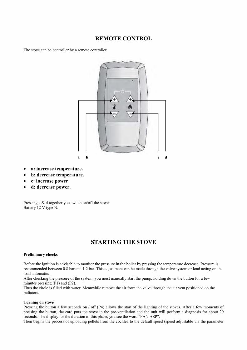
REMOTE CONTROL
The stove can be controller by a remote controller
a b c d
• a: increase temperature.
• b: decrease temperature.
• c: increase power
• d: decrease power.
Pressing a & d together you switch on/off the stove
Battery 12 V type N.
STARTING THE STOVE
Preliminary checks
Before the ignition is advisable to monitor the pressure in the boiler by pressing the temperature decrease. Pressure is
recommended between 0.8 bar and 1.2 bar. This adjustment can be made through the valve system or load acting on the
load automatic.
After checking the pressure of the system, you must manually start the pump, holding down the button for a few
minutes pressing (P1) and (P2).
Thus the circle is filled with water. Meanwhile remove the air from the valve through the air vent positioned on the
radiators.
Turning on stove
Pressing the button a few seconds on / off (P4) allows the start of the lighting of the stoves. After a few moments of
pressing the button, the card puts the stove in the pre-ventilation and the unit will perform a diagnosis for about 20
seconds. The display for the duration of this phase, you see the word "FAN ASP".
Then begins the process of uploading pellets from the cochlea to the default speed (speed adjustable via the parameter
however PR04), while phase begins ignition resistance. The display shows the words "LOAD WOOD.
When the flame and the temperature of the gas exceeds 50 ° C (PR13 parameter, which is also editable), the stove will
go into ignition mode. The display shows the words "ON FIRE".
At this stage you turn off the ignition resistance and the system verifies that the flame remains stable for a fixed time of
2 minutes (parameter PR02), after which the stove is placed in work mode.
The entire process of ignition must take place within a maximum time of 15 minutes (parameter PR01). In case this
does not occur, the system will report the power failure by displaying on top of the screen marked "ALARM" and lower
"NO ACC".
Working Phase
After the phase of "Fire On", the stoves is fully operational.
The display above is shown the power of work, adjustable using keys P5 and P6, while in the lower display (D2)
appears the temperature of the water. To adjust the water temperature desired, press the SET button (P3) once, after that
act on the buttons increase temperature (P1) and decreased temperature (P2) to set the desired value.
In this phase modulation of combustion, the size of the flame changes quickly to stabilize. If at this stage the
temperature exceeds the temperature value set or the stove shuts down, you must remove the air from the water pipes of
the stove. To do this you must remove the top of the stove and take action on the circulation of the air vent by
unscrewing the screw placed in the back: in this way the circle is filled with water and starts.
Clean the brazier
At work, the system requires that at regular intervals to do a self-cleaning of the basket. During this operation the fan
for the smoke extraction is running at full speed, while it is reduced to the minimum load pellets. The display shows the
text "PUL FIRE”.
The frequency and duration of the process of self-cleaning are identified respectively by the parameter PR03 - PR12.
Modulation
When the water temperature reaches the desired value or is close to reaching it, the stove switches to modulation.
In this condition the true power is diminished. The upper display shows the words "Mod"
Differential power
If, despite operating at reduced power mode modulation, the water temperature continues to rise, comes into play the
function on / off. Indeed, if the water temperature exceeds the set temperature of 15 ° C, and remains so for a time
interval of at least 60 minutes, the stove goes off. The display shows the text "STOP FIRE". The subsequent automatic
re-ignition occurs when the water temperature drops below 15 ° C above the temperature set.
The parameters for this function are PR12 (differential set reference H2O for power switch) and PR23 (delay for
shutdown if the temperature Thermostoves H2O> set H2O).
Setting the speed of the heat exchanger
For gas temperatures above 90 ° C, you can turn on the heat exchanger air environment. You can also control the
activity of the same acting within the setup menu set ambient air.
To enable / disable hot air blower act as below:
press twice the SET button. The display above, next to the room temperature can be set, there is a number that can take
values from 0 to 5. With subsequent press increase power (P6), you can scroll in a circle between the 5-speed available.
Placing a "0" turns off the fan.
The five available speeds are identified by parameters PR67 ÷ P71.
Turning off the stove
Through the pressure for a few seconds of the button on / off (P4) you can turn off the stove. The system will lock the
motor screw, so as to interrupt the flow of pellets in the brazier. This enhances the speed of the smoke extraction fan, in
order to ensure a rapid expulsion of gas from the combustion chamber.
After at least 10 minutes after shutdown, it also turns off the fan extraction equipment.
Service Function
The electronic card is equipped with the Service function, provided to alert the user of the completion of a cycle of
work by the stove, equal to 1300 hours. After this period of operation it is necessary to call the Technical Center
Authorized for control and maintenance.
The benchmark for the Service is PR45. To access it press and hold the SET button (P3) until the in the display appears
the inscription "UT01". Press repeatedly below the SET button until you see "UT04" and set through the buttons
temperature increase / decrease in temperature, the Code B9.
Confirming again with the SET button displays the 1300 hours by default.
And this is also the chance to see the partial working hours: press the SET button (P3) for a couple of seconds until you
see the words "UT01" in the display. Now press the SET button repeatedly (P3) until you see the words "UT04". Now
enter the code "55" from the buttons to increase / decrease in temperature and press the SET button (P3) to confirm. On
the upper display will show "ore" (service hours), while the lower display will show the real working hours of the
stove.
The electronic card also allows you to reset the partial hours. To accomplish this operation re-enter the menu technical
"UT04" and enter the code "77". Once partial reset the hours, to remove the words "Service" from the display, you must
restart the stove through the switch on the back.
Cronothermostat function
The electronic card is equipped with thermostat function through which you can set up throughout the week the
automatic switch on and off the stove at the times you want. The temperature and power which will operate the stove in
time zones correspond to those planned on the last shutdown.
The user can enter the programming by pressing the SET button (P3) for at least 2 seconds. Appear on the display
above the various parameters (UT01, UT02, UT ... 16) that can be scrolled Pressing the SET button. The display is less
than the value assumed by the parameter, editable with the buttons on increasing temperature (P1) and decreased
temperature (P2):
The parameters of the thermostat are:
• UT0 1Need to set the current day of the week or to disconnect the programming. The values that can take are listed below:
Values Meaning
DAY 1 Monday
DAY 2 Tuesday
DAY 3 Wednesday
DAY 4 Thursday
DAY 5 Friday
DAY 6 Saturday
DAY 7 Sunday
OFF No programmation
• UT02Parameter is used to set the current time. The values that can take ranging from 00 to 23.
• UT03The parameter indicates the minute currents. You can set values between 00 and 60.
• UT04Allows access to the technical parameters of the stove. You can set values between 00 and P5.
• UT05 - UT06These two parameters indicate respectively the starting time and automatic shutdown of the stove with regard to the
program 1.
Their approach is active if the parameter is set UT0 1 weekly mode, and therefore different from OFF. You can set
values from 00:00 to 23:50, for 10 minutes in 10 minutes.
• UT07Parameter allows you to select the days of the week in which you want to associate times on / off included in the
program 1. Can take only two values: ON or OFF, depending on which day of the week you want to activate /
deactivate.
• UT08 - UT09These two parameters indicate respectively the starting time and automatic shutdown of the stove with regard to the
program 2.
Their approach is active if the parameter is set UT0 1 weekly mode, and therefore different from OFF. You can set
values from 00:00 to 23:50, for 10 minutes in 10 minutes.
• UT 10
This parameter allows you to select the days of the week in which you want to associate times on / off included in the
program 2. Can take only two values: ON or OFF, depending on which day of the week you want to activate /
deactivate.
• UT11 - UT12
These two parameters indicate respectively the starting time and automatic shutdown of the stove with regard to the
program 3.
Their approach is active if the parameter is set UT01 weekly mode, and therefore different from OFF. You can set
values from 00:00 to 23:50, for 10 minutes in 10 minutes
.
• UT 13
Parameter allows you to select the days of the week in which you want to associate times on / off included in the
program 3. Can take only two values: ON or OFF, depending on which day of the week you want to activate /
deactivate.
• UT 14 - UT 15
These two parameters indicate respectively the starting time and automatic shutdown of the stove with regard to the
program 4.
Their approach is active if the parameter is set UT01 weekly mode, and therefore different from OFF. You can set
values from 00:00 to 23:50, for 10 minutes in 10 minutes.
• UT 16
This parameter allows you to select the days of the week in which you want to associate times on / off included in the
program 4. Can take only two values: ON or OFF, depending on which day of the week you want to activate /
deactivate.
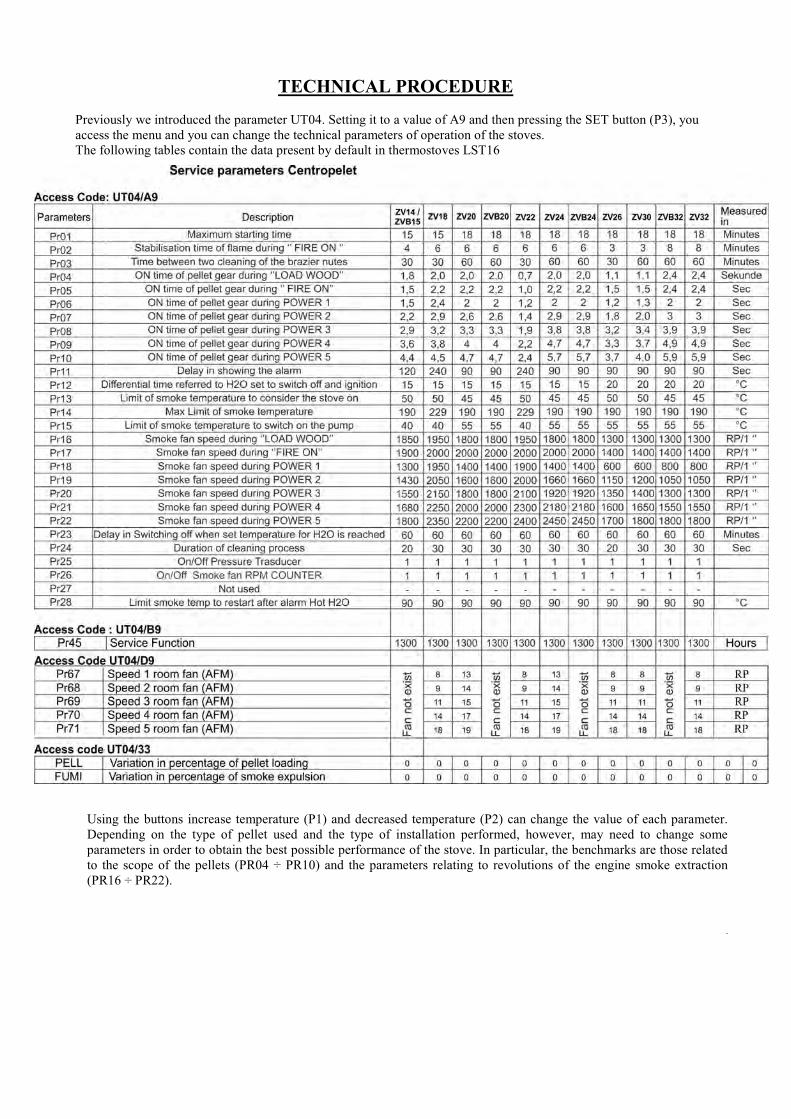
TECHNICAL PROCEDURE
Previously we introduced the parameter UT04. Setting it to a value of A9 and then pressing the SET button (P3), you
access the menu and you can change the technical parameters of operation of the stoves.
The following tables contain the data present by default in thermostoves LST16
Using the buttons increase temperature (P1) and decreased temperature (P2) can change the value of each parameter.
Depending on the type of pellet used and the type of installation performed, however, may need to change some
parameters in order to obtain the best possible performance of the stove. In particular, the benchmarks are those related
to the scope of the pellets (PR04 ÷ PR10) and the parameters relating to revolutions of the engine smoke extraction
(PR16 ÷ PR22).
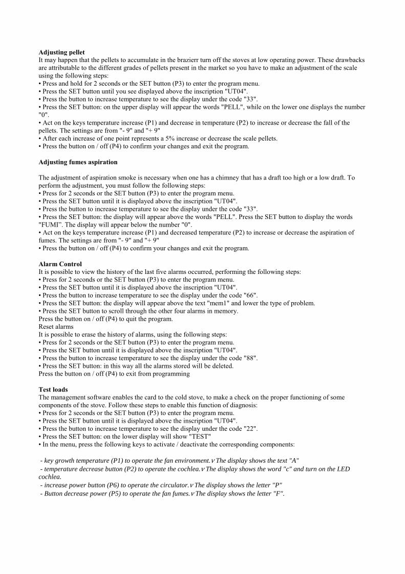
Adjusting pellet
It may happen that the pellets to accumulate in the brazierr turn off the stoves at low operating power. These drawbacks
are attributable to the different grades of pellets present in the market so you have to make an adjustment of the scale
using the following steps:
• Press and hold for 2 seconds or the SET button (P3) to enter the program menu.
• Press the SET button until you see displayed above the inscription "UT04".
• Press the button to increase temperature to see the display under the code "33".
• Press the SET button: on the upper display will appear the words "PELL", while on the lower one displays the number
"0".
• Act on the keys temperature increase (P1) and decrease in temperature (P2) to increase or decrease the fall of the
pellets. The settings are from "- 9" and "+ 9"
• After each increase of one point represents a 5% increase or decrease the scale pellets.
• Press the button on / off (P4) to confirm your changes and exit the program.
Adjusting fumes aspiration
The adjustment of aspiration smoke is necessary when one has a chimney that has a draft too high or a low draft. To
perform the adjustment, you must follow the following steps:
• Press for 2 seconds or the SET button (P3) to enter the program menu.
• Press the SET button until it is displayed above the inscription "UT04".
• Press the button to increase temperature to see the display under the code "33".
• Press the SET button: the display will appear above the words "PELL". Press the SET button to display the words
"FUMI”. The display will appear below the number "0".
• Act on the keys temperature increase (P1) and decreased temperature (P2) to increase or decrease the aspiration of
fumes. The settings are from "- 9" and "+ 9"
• Press the button on / off (P4) to confirm your changes and exit the program.
Alarm Control It is possible to view the history of the last five alarms occurred, performing the following steps:
• Press for 2 seconds or the SET button (P3) to enter the program menu.
• Press the SET button until it is displayed above the inscription "UT04".
• Press the button to increase temperature to see the display under the code "66".
• Press the SET button: the display will appear above the text "mem1" and lower the type of problem.
• Press the SET button to scroll through the other four alarms in memory.
Press the button on / off (P4) to quit the program.
Reset alarms
It is possible to erase the history of alarms, using the following steps:
• Press for 2 seconds or the SET button (P3) to enter the program menu.
• Press the SET button until it is displayed above the inscription "UT04".
• Press the button to increase temperature to see the display under the code "88".
• Press the SET button: in this way all the alarms stored will be deleted.
Press the button on / off (P4) to exit from programming
Test loads The management software enables the card to the cold stove, to make a check on the proper functioning of some
components of the stove. Follow these steps to enable this function of diagnosis:
• Press for 2 seconds or the SET button (P3) to enter the program menu.
• Press the SET button until it is displayed above the inscription "UT04".
• Press the button to increase temperature to see the display under the code "22".
• Press the SET button: on the lower display will show "TEST"
• In the menu, press the following keys to activate / deactivate the corresponding components:
- key growth temperature (P1) to operate the fan environment.ν The display shows the text "A"
- temperature decrease button (P2) to operate the cochlea.ν The display shows the word "c" and turn on the LED cochlea.
- increase power button (P6) to operate the circulator.ν The display shows the letter "P"
- Button decrease power (P5) to operate the fan fumes.ν The display shows the letter "F".

Forced load pellets Only at the stove turned off or low smoke temperature can force loading of pellets acting simultaneously on the keys
increase / decrease power (P5 and P6).
Forced activation of the circulator At cold stove you can operate the pump, through pressure contemporaneity of keys increase / decrease in temperature
(P1 and P2).
Forced activation fume extractor At cold stove and to facilitate such stages of cleaning, it is possible to operate the fan fumes.
To activate this feature, you must press the SET button (P3) and then the ON / OFF (P4). The display shows the
inscription "PUL STUF" (cleaning stove). To stop the fan, just press and hold ON / OFF (P4) or wait for a cleaning
cycle is completed (255 seconds)
Sanitary water kit
With the optional kit you can produce more hot water, without accumulation. After use chip I055, in fact, closing the
door Contact flux the stove heating mode circuit of sanitary water. Under these conditions, the system requires that the
oven is brought to maximum power and that the 3 port valve is deflected position in healthcare. The display shows the
word "SANI."
For water temperatures above 75 ° C, the boiler comes in modules and lowers operational power. If, however, the water
temperature continues to rise, for values higher than 82 ° C, the boiler is turned off. Water temperatures above 85 ° C
would still alarmed by the stove overheating.
The pressure the sanitary water should not exceed 2.5 bar.
External thermostat
The electronic board provides an input for an external thermostat on connector CN7, particularly on the terminals
identified by screen printing "TERM". To connect simply remove the jumper between the two terminals and connect
the two wires from the external thermostat.
When the thermostat reaches the set temperature on the display of stoves will appear the inscription "TOFF".
The thermostat is not implementing the function to turn off and turn on the stove, but puts it in savings.
Management puffer
The card allows you to manage the temperature of the water contained in a storage tank.
It is necessary to extend or replace the temperature sensor (connector CN / pin 5-6), in order to bring it inside the
storage tank.
Once this is done, to enable the puffer, you must enter the menu technical UT04 and, through the keys increase /
decrease in temperature, insert the code "C9". Press the SET button (P3) to confirm.
At this point it is sufficient, again via the keys increase / decrease in temperature, to set to "1" parameter PR60 (defaults
to "0"). Press SET (P3) to confirm and exit.
Pressing the SET button twice in succession (P3), instead of the setup menu of the temperature, we find the possibility
to select the temperature inside the water tank. The display appears below the words "Set Puff", while the upper display
displays the temperature of the water that you can set. The range varies from 50 ° C to 80 ° C, selectable via the buttons
increase / decrease in temperature (P1/P2).
ALARMS
The electronic board shall report, through the display, any errors or anomalies that may occur during normal operation
of the stove.
Alarms can be reset using the power button on / off (P4).
• Faulty gas probeIn case of failure or lack of connection of the probe gas control system immediately stops the fall of the pellets in the
brazier. It generates an alarm "ALARM SOND FUMI" and begins the process of extinguishing the stoves. Press the on /
off (P4) to reset the alarm.
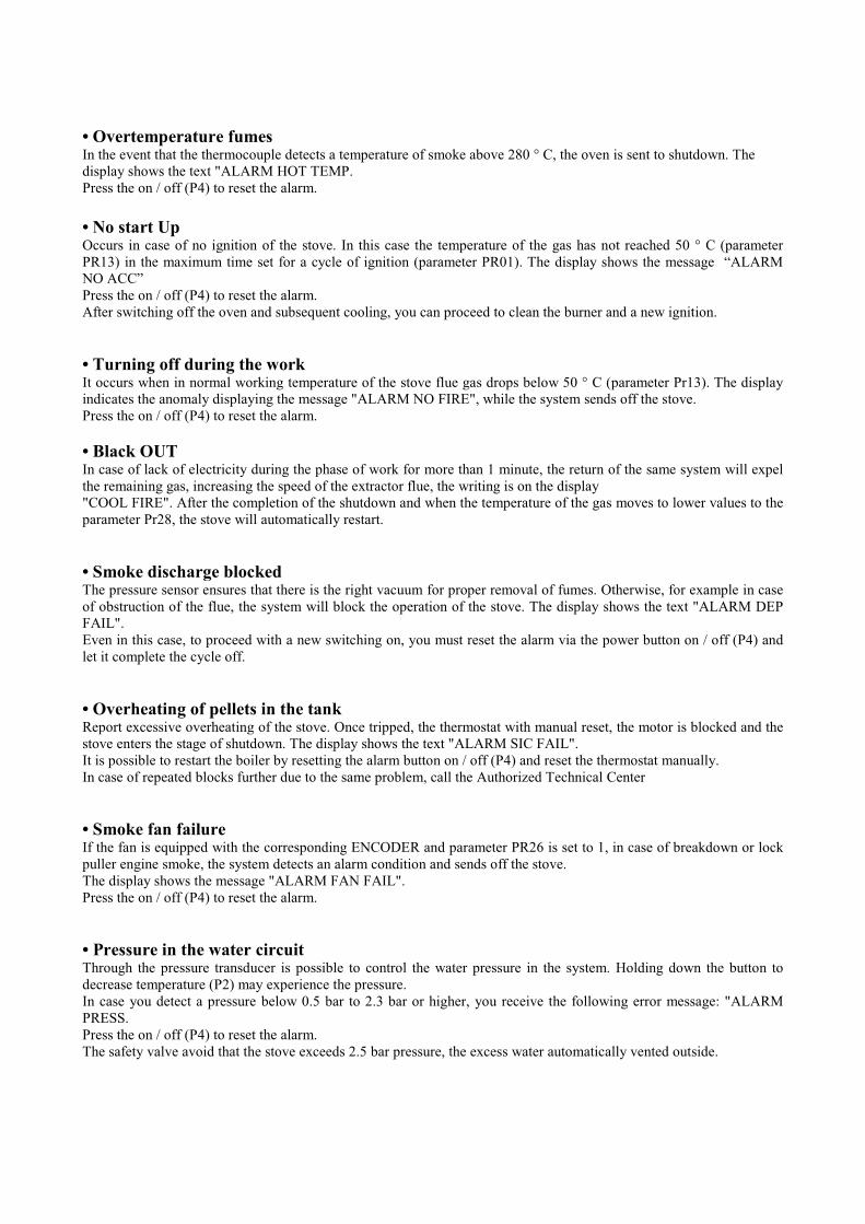
• Overtemperature fumesIn the event that the thermocouple detects a temperature of smoke above 280 ° C, the oven is sent to shutdown. The
display shows the text "ALARM HOT TEMP.
Press the on / off (P4) to reset the alarm.
• No start UpOccurs in case of no ignition of the stove. In this case the temperature of the gas has not reached 50 ° C (parameter
PR13) in the maximum time set for a cycle of ignition (parameter PR01). The display shows the message “ALARM
NO ACC”
Press the on / off (P4) to reset the alarm.
After switching off the oven and subsequent cooling, you can proceed to clean the burner and a new ignition.
• Turning off during the workIt occurs when in normal working temperature of the stove flue gas drops below 50 ° C (parameter Pr13). The display
indicates the anomaly displaying the message "ALARM NO FIRE", while the system sends off the stove.
Press the on / off (P4) to reset the alarm.
• Black OUTIn case of lack of electricity during the phase of work for more than 1 minute, the return of the same system will expel
the remaining gas, increasing the speed of the extractor flue, the writing is on the display
"COOL FIRE". After the completion of the shutdown and when the temperature of the gas moves to lower values to the
parameter Pr28, the stove will automatically restart.
• Smoke discharge blockedThe pressure sensor ensures that there is the right vacuum for proper removal of fumes. Otherwise, for example in case
of obstruction of the flue, the system will block the operation of the stove. The display shows the text "ALARM DEP
FAIL".
Even in this case, to proceed with a new switching on, you must reset the alarm via the power button on / off (P4) and
let it complete the cycle off.
• Overheating of pellets in the tankReport excessive overheating of the stove. Once tripped, the thermostat with manual reset, the motor is blocked and the
stove enters the stage of shutdown. The display shows the text "ALARM SIC FAIL".
It is possible to restart the boiler by resetting the alarm button on / off (P4) and reset the thermostat manually.
In case of repeated blocks further due to the same problem, call the Authorized Technical Center
• Smoke fan failureIf the fan is equipped with the corresponding ENCODER and parameter PR26 is set to 1, in case of breakdown or lock
puller engine smoke, the system detects an alarm condition and sends off the stove.
The display shows the message "ALARM FAN FAIL".
Press the on / off (P4) to reset the alarm.
• Pressure in the water circuitThrough the pressure transducer is possible to control the water pressure in the system. Holding down the button to
decrease temperature (P2) may experience the pressure.
In case you detect a pressure below 0.5 bar to 2.3 bar or higher, you receive the following error message: "ALARM
PRESS.
Press the on / off (P4) to reset the alarm.
The safety valve avoid that the stove exceeds 2.5 bar pressure, the excess water automatically vented outside.
• Exceeding water temperatureWhere the water temperature exceeds 90 ° C, the electronic controller switches off the stove. The display shows
"ALARM HOT H20. This problem may occur in the case of circulation pump blocked or because of the hydraulic
discharge of water.
Press the on / off (P4) to reset the alarm.
• Excessive Overtemperature waterIf the probe detects a water temperature above 100 ° C, the system will send the stove off. A display shows the text
"ALARM SIC FAIL".
Press the on / off (P4) to reset the alarm and reset the thermostat of water safety on the back stove. Proceed with a new
ignition.
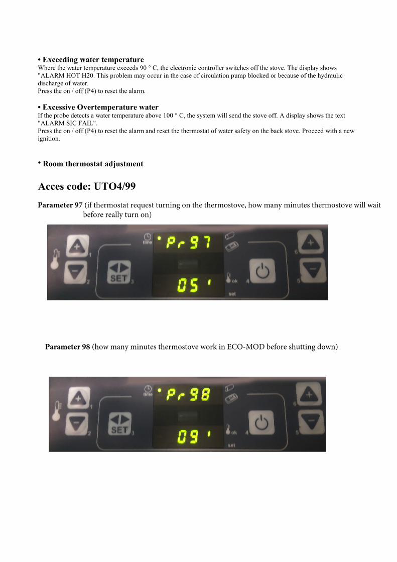
• Room thermostat adjustment
Acces code: UTO4/99
Parameter 97 (if thermostat request turning on the thermostove, how many minutes thermostove will wait before really turn on)
Parameter 98 (how many minutes thermostove work in ECO-MOD before shutting down)

Working with accumulation tank (puffer)
1. You have to remove the ambient sensor and install a long sensor and put it into the puffer.
2. Press set and enter into UT04, insert the key C9. Now you will see PR60=0, you have to change to 1 forenable puffur. Now the puffer system is enable and you can set the water temperature in the puffer.
3. If you set temperature puffer at 60°C, the water in the thermostove is automatically set at 68°C. Waterthermostove temperature is automatically set at set temperature puffer + 8°C.
4. If water thermostove temperature > water puffer temperature the pump turns on.
5. If water puffer temperature > puffer temperature set by customer, the stove waits until that thetemperature rises by 3°C and after 2 minuts the stove switches off. In the display you will see ECO ATTE / STOP FIRE / °C(PUFF)°C.
6. The thermostoves switches on when the water puffer temperature is lower by 2°C than water puffertemperature set by customer
7. If the water thermostove temperature > set temperature puffer + 8°C, the thermostove works at minimumpower (ECO mode).
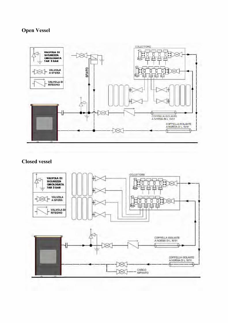
Open Vessel
Closed vessel
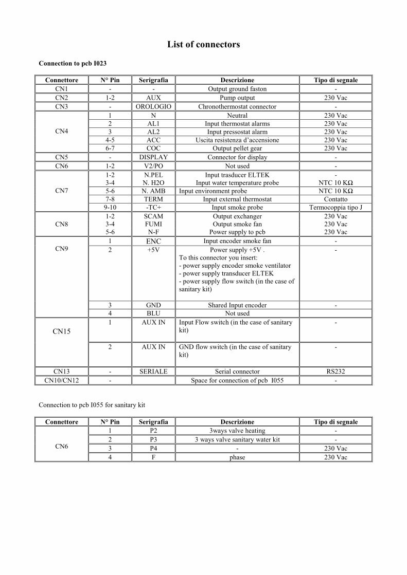
List of connectors
Connection to pcb I023
Connettore N° Pin Serigrafia Descrizione Tipo di segnale
CN1 - - Output ground faston -
CN2 1-2 AUX Pump output 230 Vac
CN3 - OROLOGIO Chronothermostat connector -
1 N Neutral 230 Vac
2 AL1 Input thermostat alarms 230 Vac
3 AL2 Input pressostat alarm 230 Vac
4-5 ACC Uscita resistenza d’accensione 230 Vac
CN4
6-7 COC Output pellet gear 230 Vac
CN5 - DISPLAY Connector for display -
CN6 1-2 V2/PO Not used -
1-2 N.PEL Input trasducer ELTEK -
3-4 N. H2O Input water temperature probe NTC 10 K�
5-6 N. AMB Input environment probe NTC 10 K�
7-8 TERM Input external thermostat Contatto
CN7
9-10 -TC+ Input smoke probe Termocoppia tipo J
1-2 SCAM Output exchanger 230 Vac
3-4 FUMI Output smoke fan 230 Vac CN8
5-6 N-F Power supply to pcb 230 Vac
1 ENC Input encoder smoke fan -
2 +5V Power supply +5V .
To this connector you insert:
- power supply encoder smoke ventilator
- power supply transducer ELTEK
- power supply flow switch (in the case of
sanitary kit)
-
3 GND Shared Input encoder -
CN9
4 BLU Not used
1 AUX IN Input Flow switch (in the case of sanitary
kit)
-
CN15
2 AUX IN GND flow switch (in the case of sanitary
kit)
-
CN13 - SERIALE Serial connector RS232
CN10/CN12 - Space for connection of pcb I055 -
Connection to pcb I055 for sanitary kit
Connettore N° Pin Serigrafia Descrizione Tipo di segnale
1 P2 3ways valve heating -
2 P3 3 ways valve sanitary water kit -
3 P4 - 230 Vac CN6
4 F phase 230 Vac

HEATING TECHNIQUE
www.centrometal.hre-mail: [email protected]
Centrometal d.o.o. Glavna 12, 40306 Macinec, Croatia
central tel: +385 40 372 600, fax: +385 40 372 611service tel: +385 40 372 622, fax: +385 40 372 621
Company shall not be responsible for possible incorrect data caused by printing errors or error made in transcription and all figures and diagrams are for explanatory purposes only and relevant adjustment have to be made at the spot. In any case, it reserves the right to modify its products as deemed to be required and useful without any prior notification.