Embed Size (px)
Citation preview
VDM® Alloy 718
Nicrofer 5219 Nb
Material Data Sheet No. 4127
June 2016
June 2016 VDM® Alloy 718 2
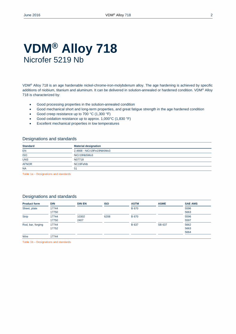
VDM® Alloy 718 is an age hardenable nickel-chrome-iron-molybdenum alloy. The age hardening is achieved by specific
additions of niobium, titanium and aluminum. It can be delivered in solution-annealed or hardened condition. VDM® Alloy
718 is characterized by:
Good processing properties in the solution-annealed condition
Good mechanical short and long-term properties, and great fatigue strength in the age hardened condition
Good creep resistance up to 700 °C (1,300 °F)
Good oxidation resistance up to approx. 1,000°C (1,830 °F)
Excellent mechanical properties in low temperatures
Designations and standards
Standard Material designation
EN 2.4668 - NiCr19Fe19Nb5Mo3
ISO NiCr19Nb5Mo3
UNS N07718
AFNOR NC19FeNb
NA 51
Table 1a – Designations and standards
Designations and standards
Product form DIN DIN EN ISO ASTM ASME SAE AMS
Sheet, plate 17744
17750
B 670 5596
5663
Strip 17744
17750
10302
2407
6208 B 670 5596
5597
Rod, bar, forging 17744
17752
B 637 SB 637 5662
5663
5664
Wire 17744
Table 1b – Designations and standards
VDM® Alloy 718 Nicrofer 5219 Nb
June 2016 VDM® Alloy 718 3
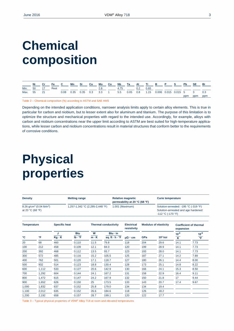
Chemical composition
Ni Cr Fe C Mn Si Cu Mo Co Nb Ta Al Ti B P S Pb SE Bi
Min. 50 17 Rest 2.8 4.75 0.2 0.65
Max. 55 21 0.08 0.35 0.35 0.3 3.3 1 5.5 0.05 0.8 1.15 0.006 0.015 0.015 5
ppm
3
ppm
0.3
ppm
Table 2 – Chemical composition (%) according to ASTM and SAE AMS
Depending on the intended application conditions, narrower analysis limits apply to certain alloy elements. This is true in
particular for carbon and niobium, but to lesser extent also for aluminum and titanium. The purpose of this limitation is to
optimize the structure and mechanical properties with regard to the intended use. Accordingly, for example, alloys with
carbon and niobium concentrations near the upper limit according to ASTM are best suited for high-temperature applica-
tions, while lesser carbon and niobium concentrations result in material structures that conform better to the requirements
of corrosive conditions.
Physical properties
Density Melting range Relative magnetic
permeability at 20 °C (68 °F)
Curie temperature
8.26 g/cm3 (0.04 lb/in3)
at 20 °C (68 °F)
1,257-1,342 °C (2,295-2,448 °F) 1.001 (Maximum) Solution-annealed: -195 °C (-319 °F)
Solution-annealed and age hardened:
-112 °C (-170 °F)
Temperature Specific heat Thermal conductivity Electrical
resistivity
Modulus of elasticity Coefficient of thermal
expansion
°C
°F
J
Kg · K
Btu
lb ∙ °F
W
m ∙ K
Btu ∙ in
sq. ft ∙ h ∙ °F
μΩ · cm
GPa
103 ksi 10
-6
K
10-6
°F
20 68 460 0.110 11.5 79.8 118 204 29.6 14.1 7.73
100 212 458 0.109 12.1 84.0 120 199 28.9 14.1 7.73
200 392 468 0.112 13.5 93.7 123 193 28.0 14.1 7.73
300 572 485 0.116 15.2 105.5 125 187 27.1 14.2 7.89
400 762 501 0.120 17.1 118.7 127 180 26.1 14.4 8.00
500 932 514 0.123 18.8 130.4 128 173 25.1 14.8 8.22
600 1,112 533 0.127 20.6 142.9 130 166 24.1 15.3 8.50
700 1,292 604 0.144 24.1 167.2 131 158 22.9 16.4 9.11
800 1,472 615 0.147 24.2 167.9 132 150 21.8 17 9.44
900 1,652 626 0.150 25 173.5 133 143 20.7 17.4 9.67
1,000 1,832 637 0.152 25.8 179.0 134 134 19.4
1,100 2,012 635 0.152 26.6 184.6 118 126 18.2
1,200 2,192 658 0.157 28.7 199.1 120 122 17.7
Table 3 – Typical physical properties of VDM® Alloy 718 at room and elevated temperatures
June 2016 VDM® Alloy 718 4
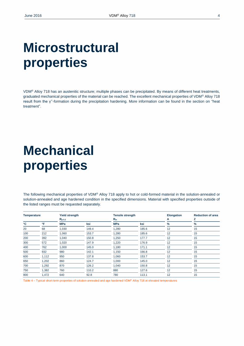
Microstructural properties
VDM® Alloy 718 has an austenitic structure; multiple phases can be precipitated. By means of different heat treatments,
graduated mechanical properties of the material can be reached. The excellent mechanical properties of VDM® Alloy 718
result from the γ’’-formation during the precipitation hardening. More information can be found in the section on “heat
treatment”.
Mechanical properties
The following mechanical properties of VDM® Alloy 718 apply to hot or cold-formed material in the solution-annealed or
solution-annealed and age hardened condition in the specified dimensions. Material with specified properties outside of
the listed ranges must be requested separately.
Temperature Yield strength
Rp 0.2
Tensile strength
Rm
Elongation
A
Reduction of area
Z
°C °F MPa ksi MPa ksi % %
20 68 1,030 149.4 1,280 185.6 12 15
100 212 1,060 153.7 1,280 185.6 12 15
200 392 1,040 150.8 1,250 177.7 12 15
300 572 1,020 147.9 1,220 176.9 12 15
400 762 1,000 145.0 1,180 171.1 12 15
500 932 980 142.1 1,150 166.8 12 15
600 1,112 950 137.8 1,060 153.7 12 15
650 1,202 860 124.7 1,000 145.0 12 15
700 1,292 870 126.2 1,040 150.8 12 15
750 1,382 760 110.2 880 127.6 12 15
800 1,472 640 92.8 780 113.1 12 15
Table 4 – Typical short-term properties of solution-annealed and age hardened VDM® Alloy 718 at elevated temperatures
June 2016 VDM® Alloy 718 5
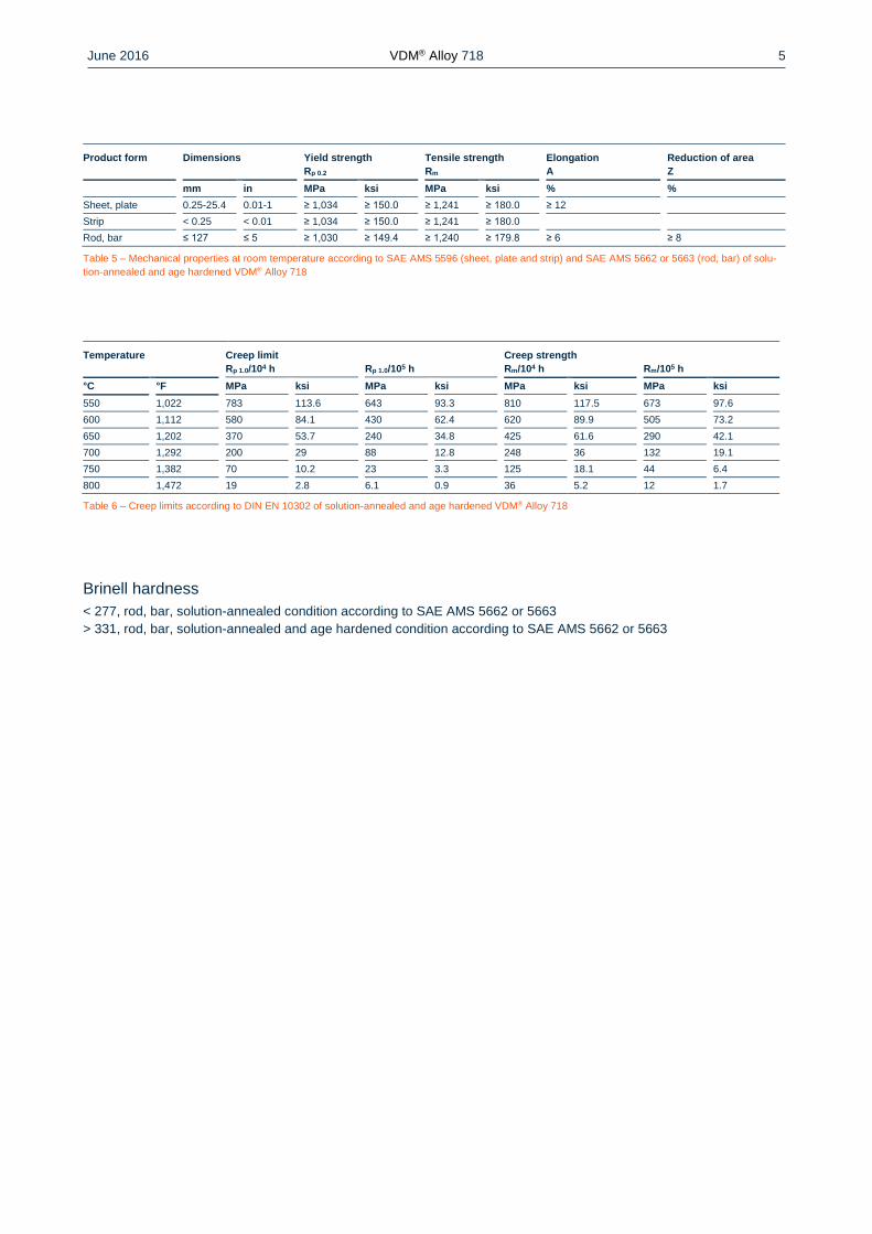
Product form Dimensions
Yield strength
Rp 0.2
Tensile strength
Rm
Elongation
A
Reduction of area
Z
mm in MPa ksi MPa ksi % %
Sheet, plate 0.25-25.4 0.01-1 ≥ 1,034 ≥ 150.0 ≥ 1,241 ≥ 180.0 ≥ 12
Strip < 0.25 < 0.01 ≥ 1,034 ≥ 150.0 ≥ 1,241 ≥ 180.0
Rod, bar ≤ 127 ≤ 5 ≥ 1,030 ≥ 149.4 ≥ 1,240 ≥ 179.8 ≥ 6 ≥ 8
Table 5 – Mechanical properties at room temperature according to SAE AMS 5596 (sheet, plate and strip) and SAE AMS 5662 or 5663 (rod, bar) of solu-
tion-annealed and age hardened VDM® Alloy 718
Temperature Creep limit
Rp 1.0/104 h
Rp 1.0/105 h Creep strength
Rm/104 h
Rm/105 h
°C °F MPa ksi MPa ksi MPa ksi MPa ksi
550 1,022 783 113.6 643 93.3 810 117.5 673 97.6
600 1,112 580 84.1 430 62.4 620 89.9 505 73.2
650 1,202 370 53.7 240 34.8 425 61.6 290 42.1
700 1,292 200 29 88 12.8 248 36 132 19.1
750 1,382 70 10.2 23 3.3 125 18.1 44 6.4
800 1,472 19 2.8 6.1 0.9 36 5.2 12 1.7
Table 6 – Creep limits according to DIN EN 10302 of solution-annealed and age hardened VDM® Alloy 718
Brinell hardness
< 277, rod, bar, solution-annealed condition according to SAE AMS 5662 or 5663
> 331, rod, bar, solution-annealed and age hardened condition according to SAE AMS 5662 or 5663
June 2016 VDM® Alloy 718 6
Corrosion resistance
Based on the high chrome and molybdenum concentrations, VDM® Alloy 718 has a good resistance in many media against
abrasive and local corrosion such as pitting. By virtue of its high nickel content, VDM® Alloy 718 also has good resistance
against stress corrosion cracking.
Applications
Based on its high-temperature resistance up to 700 °C (1,300 °F), its excellent oxidation and corrosion resistance, and its
good workability, VDM® Alloy 718 is used in many demanding applications. Originally, it was developed and used for static
and rotating components in aircraft turbines such as housings, mounting elements and turbine disks, where tough require-
ments apply for creep resistance and fatigue behavior, in particular for the rotating applications.
Due to its properties, its good workability and efficiency, the material is additionally widely used for static and rotating
components in stationary gas turbines, rocket drives and spacecraft, motor vehicle turbo chargers, high-strength screws,
springs and mounting elements, and for heat-resistant tools in forgeries, extruders and separating shearers.
The variant VDM® Alloy 718 CTP, which is laid out specifically for the requirements of the oil and gas industry, finds
increasing uses in drilling equipment and pump shafts. The components used must ensure an efficient and safe oil and
gas extraction with increasing drilling hole depth and pressures and temperatures becoming more critical, and withstand
the acid gas environment (H2S, CO2, chloride) that is prevalent there (see special data sheet VDM® Alloy 718 CTP).
June 2016 VDM® Alloy 718 7
Fabrication and heat treatment
VDM® Alloy 718 can readily be hot- and cold-worked and machined.
Heating
Workpieces must be clean and free of any contaminants before and during heat treatment. Sulfur, phosphor, lead and
other low-melting-point metals can lead to damages when heat treating VDM® Alloy 718. Sources of such contaminants
include marking and temperature-indicating paints and crayons, lubricating grease and fluids, and fuels. Heat treatments
can be carried out in gas fired, oil fired or electric furnaces in air, under vacuum or inert gas atmosphere. Fuels should
contain as little sulfur as possible. Natural gas should contain less than 0.1 wt.-% of sulfur. Heating oil with a sulfur content
of maximum 0.5 wt.-% is also suitable with a slightly oxidizing atmosphere. The workpieces may not be contacted directly
by flames.
Hot working
The hot working should generally be conducted after the homogenization with subsequent cooling in air. It should be done
evenly in order to receive a homogeneous structure and to prevent the formation of a duplex grain structure.
Cold working
Cold working should take place in the solution-annealed condition. The material has a higher work hardening rate than
austenitic stainless steels. This must be taken into account during design and selection of forming tools and equipment
and during the planning of the forming processes.
Heat treatment
Through various heat treatments, the mechanical properties of VDM® Alloy 718 can be adjusted specifically. In the solu-
tion-annealed condition, the material can be processed and worked more easily. In the solution-annealed and age hard-
ened condition, VDM® Alloy 718 has a high mechanical strength. The solution-annealed condition is obtained through a
heat treatment in the temperature range from 940 to 1,065 °C (1,724 to 1,949 °F). Here, for example, annealing by insert-
ing into a pre-heated furnace at a temperature of 980 °C (1,796 °F) for 1 hour is common. Cooling can be done by placing
the workpiece in water or oil or also in open air. The hardening takes place by annealing in the temperature range from
620 to 790 °C (1,148 to 1,454 °F). A two-stage heat treatment is common here with insertion in a pre-heated furnace at
720 °C (1,328 °F) for 8 hours, followed by a furnace cool-down to 620 °C (1,148 °F) and repeated holding for 8 hours.
Cooling is usually done in open air.
Descaling and pickling
Oxides from VDM® Alloy 718 and discoloration adjacent to welds are more adherent than on stainless steels. Grinding
with very fine abrasive belts or discs is recommended. Care should be taken to prevent tarnishing. Before pickling which
may be performed in a nitric/hydrofluoric acid mixture with proper control of pickling time and temperature, the surface
oxide layer must be broken up by abrasive blasting or by carefully performed grinding.
Machining
While VDM® Alloy 718 in the solution-annealed condition is easier to process and the strain on tools is less, better surface
quality is achieved in the hardened condition. The best results in terms of the surface quality of the finished product are
achieved by pre-treatment before hardening and by finishing in the hardened condition. As the alloy is more prone to work-
hardening than other low alloyed materials, low cutting speeds and appropriate feed rates should be used and the tool
should stay engaged at all times. Sufficient chip depths are important to get below the work-hardened surface layer.
June 2016 VDM® Alloy 718 8
Welding
When welding nickel alloys and special stainless steels, the following information should be taken into account:
Workplace
A separately located workplace, which is specifically separated from areas in which carbon steels are being processed,
must be provided. Considerable cleanliness is required, and draughts should be avoided during inert gas welding.
Auxiliary equipment and clothing
Clean fine leather gloves and clean working clothes must be used.
Tools and machines
Tools that have been used for other materials may not be used for nickel alloys and stainless steels. Only stainless steel
brushes may be used. Processing and treatment machines such as shears, punches or rollers must be fitted (felt, card-
board, films) so that the workpiece surfaces cannot be damaged by the pressing in of iron particles through such equip-
ment, as this can lead to corrosion.
Welding edge preparation
Welding edge preparation should preferably be carried out using mechanical methods through lathing, milling or planing.
Abrasive waterjet cutting or plasma cutting is also possible. In the latter case, however, the cut edge (seam flank) must
be cleanly reworked. Careful grinding without overheating is also permissible.
Scaling
Scaling may only be carried out in the seam area, e.g. along the seam flanks or outlets, and should not be carried out on
the workpiece surface. Scaling areas are areas in which corrosion more easily occurs.
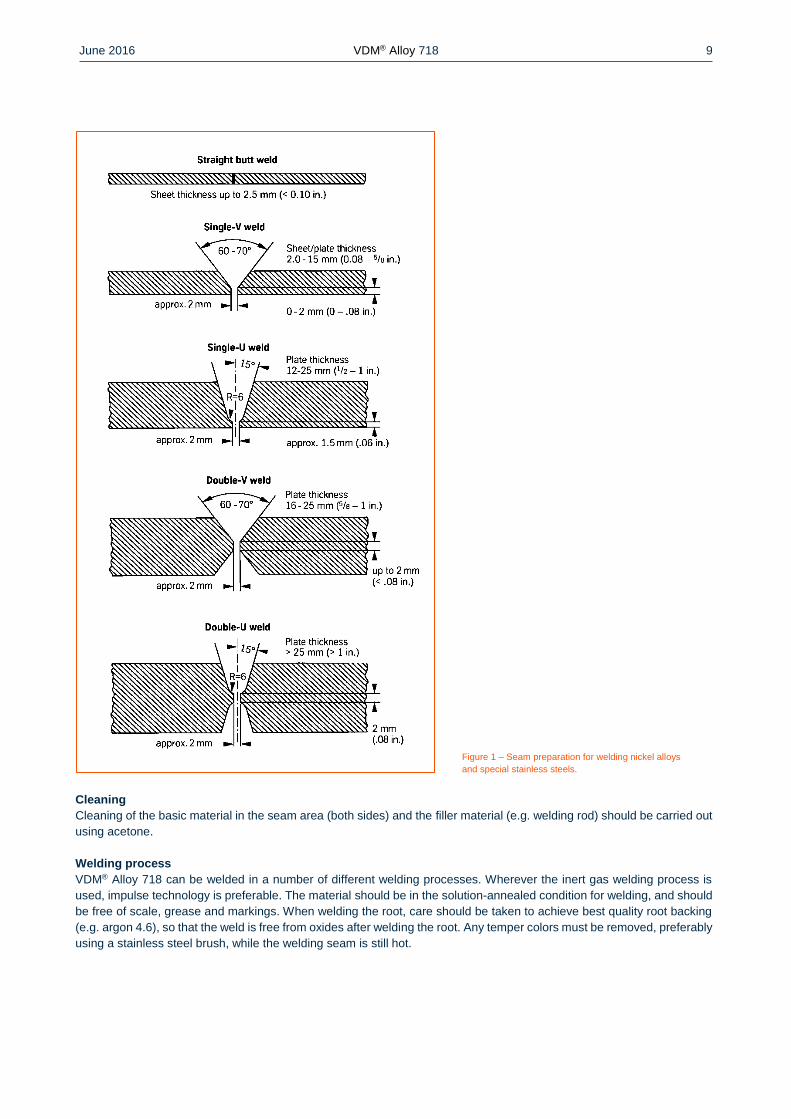
Included angle
Compared to carbon steels, nickel alloys and special stainless steels have a lower heat conductivity and greater heat
expansion. These properties must be taken into account by a larger root openings or root gaps (1 to 3 mm; 0.04-1.2 in).
Due to the viscosity of the welding material (compared to standard austenites) and the tendency to shrink, opening angles
of 60 to 70° – as shown in Figure 1 – must be provided for butt welds.
June 2016 VDM® Alloy 718 9
Figure 1 – Seam preparation for welding nickel alloys
and special stainless steels.
Cleaning
Cleaning of the basic material in the seam area (both sides) and the filler material (e.g. welding rod) should be carried out
using acetone.
Welding process
VDM® Alloy 718 can be welded in a number of different welding processes. Wherever the inert gas welding process is
used, impulse technology is preferable. The material should be in the solution-annealed condition for welding, and should
be free of scale, grease and markings. When welding the root, care should be taken to achieve best quality root backing
(e.g. argon 4.6), so that the weld is free from oxides after welding the root. Any temper colors must be removed, preferably
using a stainless steel brush, while the welding seam is still hot.
June 2016 VDM® Alloy 718 10
Filler material
The following filler materials are recommended:
TIG/MIG
VDM® FM 718 (W. no. 2.4667)
DIN EN ISO 18274: S Ni 7718 (SG-NiCr19NbMoTi)
AWS A 5.14: ERNiFeCr-2
The use of bar electrodes in sleeves is possible.
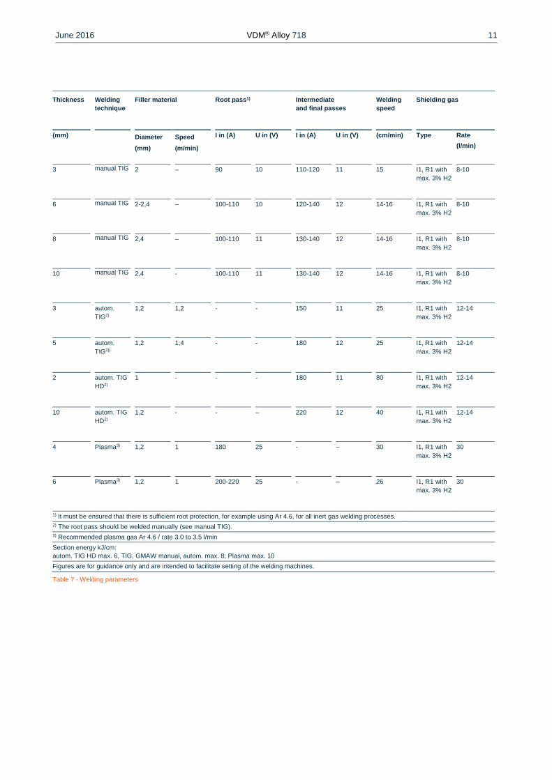
Welding parameters and influences
It must be ensured that work is carried out using targeted heat application and low heat input. The interpass temperature
should not exceed 100 °C (212 °F). The stringer bead technique is recommended. In this context, also the right choice of
wire and bar electrode diameters should be pointed out. Corresponding energy inputs per unit length result from the
aforementioned notes, which are shown as examples in Table 7. In principle, checking of welding parameters is necessary.
Heat input Q can be calculated as follows:
Q=U · I · 60
v · 1.000 (
kJ
cm)
U = arc voltage, Volt
I = welding current voltage, Ampere
v = welding speed, cm/minute
Post-weld treatment
During optimum implementation of the work brushing directly after welding, in other words, in a hot condition, without
additional pickling results in the required surface condition, i.e. temper color can be removed completely. Once the welding
work is finished, hardening can be conducted to achieve a maximum of firmness. On this topic, see the section “Heat
treatment": Pickling, if required or specified, should generally be the last operation in the welding process. Information
contained in the section entitled "Descaling and pickling" must be observed.
June 2016 VDM® Alloy 718 11
Thickness Welding
technique
Filler material Root pass1) Intermediate
and final passes
Welding
speed
Shielding gas
(mm) Diameter
(mm)
Speed
(m/min)
I in (A) U in (V) I in (A) U in (V) (cm/min) Type Rate
(l/min)
3 manual TIG 2 – 90 10 110-120 11 15 I1, R1 with
max. 3% H2
8-10
6 manual TIG 2-2,4 – 100-110 10 120-140 12 14-16 I1, R1 with
max. 3% H2
8-10
8 manual TIG 2,4 – 100-110 11 130-140 12 14-16 I1, R1 with
max. 3% H2
8-10
10 manual TIG 2,4 - 100-110 11 130-140 12 14-16 I1, R1 with
max. 3% H2
8-10
3 autom.
TIG2)
1,2 1,2 - - 150 11 25 I1, R1 with
max. 3% H2
12-14
5 autom.
TIG2))
1,2 1,4 - - 180 12 25 I1, R1 with
max. 3% H2
12-14
2 autom. TIG
HD2)
1 - - - 180 11 80 I1, R1 with
max. 3% H2
12-14
10 autom. TIG
HD2)
1,2 - - – 220 12 40 I1, R1 with
max. 3% H2
12-14
4 Plasma3) 1,2 1 180 25 - – 30 I1, R1 with
max. 3% H2
30
6 Plasma3) 1,2 1 200-220 25 - – 26 I1, R1 with
max. 3% H2
30
1) It must be ensured that there is sufficient root protection, for example using Ar 4.6, for all inert gas welding processes.
2) The root pass should be welded manually (see manual TIG).
3) Recommended plasma gas Ar 4.6 / rate 3.0 to 3.5 l/min
Section energy kJ/cm:
autom. TIG HD max. 6, TIG, GMAW manual, autom. max. 8; Plasma max. 10
Figures are for guidance only and are intended to facilitate setting of the welding machines.
Table 7 - Welding parameters
June 2016 VDM® Alloy 718 12
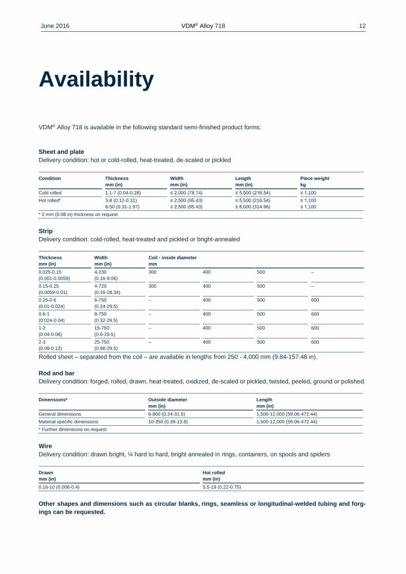
Availability
VDM® Alloy 718 is available in the following standard semi-finished product forms:
Sheet and plate
Delivery condition: hot or cold-rolled, heat-treated, de-scaled or pickled
Condition Thickness
mm (in)
Width
mm (in)
Length
mm (in)
Piece weight
kg
Cold rolled 1.1-7 (0.04-0.28) ≤ 2,000 (78.74) ≤ 5,500 (216.54) ≤ 1,100
Hot rolled* 3-8 (0.12-0.31)
8-50 (0.31-1.97)
≤ 2,500 (95.43)
≤ 2,500 (95.43)
≤ 5,500 (216.54)
≤ 8,000 (314.96)
≤ 1,100
≤ 1,100
* 2 mm (0.08 in) thickness on request
Strip
Delivery condition: cold-rolled, heat-treated and pickled or bright-annealed
Thickness
mm (in)
Width
mm (in)
Coil - inside diameter
mm
0,025-0,15
(0.001-0.0059)
4-230
(0.16-9.06)
300 400 500 –
0.15-0.25
(0.0059-0.01)
4-720
(0.16-28.34)
300 400 500 –
0.25-0.6
(0.01-0.024)
6-750
(0.24-29.5)
– 400 500 600
0.6-1
(0.024-0.04)
8-750
(0.32-29.5)
– 400 500 600
1-2
(0.04-0.08)
15-750
(0.6-29.5)
– 400 500 600
2-3
(0.08-0.12)
25-750
(0.98-29.5)
– 400 500 600
Rolled sheet – separated from the coil – are available in lengths from 250 - 4,000 mm (9.84-157.48 in).
Rod and bar
Delivery condition: forged, rolled, drawn, heat-treated, oxidized, de-scaled or pickled, twisted, peeled, ground or polished.
Dimensions* Outside diameter
mm (in)
Length
mm (in)
General dimensions 6-800 (0.24-31.5) 1,500-12,000 (59.06-472.44)
Material specific dimensions 10-350 (0.39-13.8) 1,500-12,000 (59.06-472.44)
* Further dimensions on request
Wire
Delivery condition: drawn bright, ¼ hard to hard, bright annealed in rings, containers, on spools and spiders
Drawn
mm (in)
Hot rolled
mm (in)
0.16-10 (0.006-0.4) 5.5-19 (0.22-0.75)
Other shapes and dimensions such as circular blanks, rings, seamless or longitudinal-welded tubing and forg-
ings can be requested.
June 2016 VDM® Alloy 718 13
30 June 2016 Publisher
VDM Metals International GmbH Plettenberger Straße 2 58791 Werdohl Germany
Disclaimer
All information contained in this data sheet is based on the results of research and development work carried out by VDM
Metals International GmbH and the data contained in the specifications and standards listed available at the time of print-
ing. The information does not represent a guarantee of specific properties. VDM Metals reserves the right to change
information without notice. All information contained in this data sheet is compiled to the best of our knowledge and is
provided without liability. Deliveries and services are subject exclusively to the relevant contractual conditions and the
General Terms and Conditions issued by VDM Metals. Use of the most up-to-date version of this data sheet is the re-
sponsibility of the customer.
Imprint
VDM Metals International GmbH
Plettenberger Straße 2
58791 Werdohl
Germany
Phone +49 (0)2392 55 0
Fax +49 (0)2392 55 22 17
www.vdm-metals.com