Embed Size (px)
Citation preview
— D IS TR I BUTI ON SOLUTI ONS
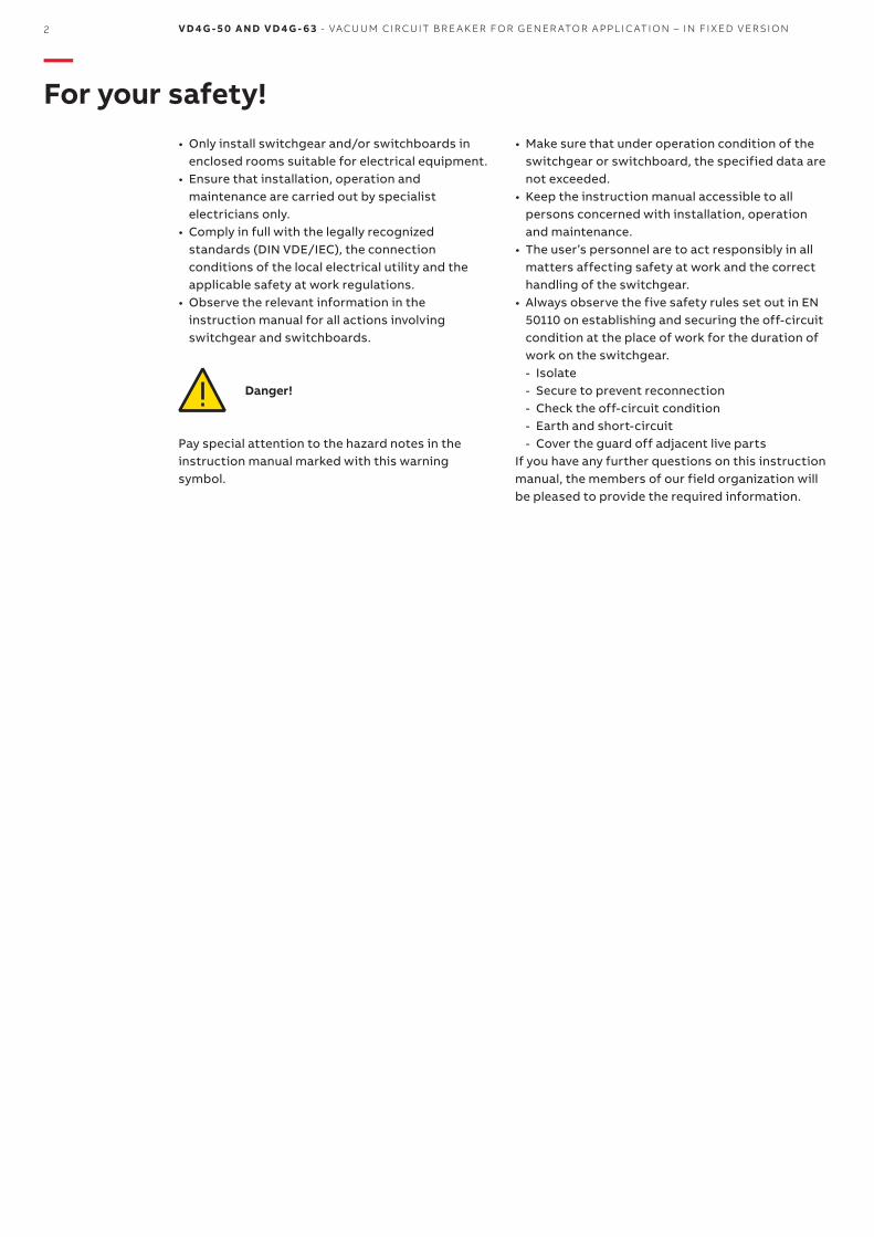
VD4G-50 and VD4G-63Vacuum circuit breaker for generatorapplication – in fixed version
ContentsFor your safety! 21 Summary 32 Technical data 43 Structure and function 84 Despatch and storage 125 Installation 136 Commissioning / Operation 147 Maintenance 168 Application of the X-ray regulations 249 Comparison of designations to
IEC 81346-1/IEC 81346-2, IEC 61346-1/IEC 61346-2 and VDE-DIN 40719 Part 2 25
2 V D 4 G - 5 0 A N D V D 4 G - 6 3 - VAC U U M CI R C U IT B R E A K ER FO R G EN ER ATO R A PPL I C ATI O N – I N FI X ED V ER SI O N
Danger!
—For your safety!
• Only install switchgear and/or switchboards in enclosed rooms suitable for electrical equipment.
• Ensure that installation, operation and maintenance are carried out by specialist electricians only.
• Comply in full with the legally recognized standards (DIN VDE/IEC), the connection conditions of the local electrical utility and the applicable safety at work regulations.
• Observe the relevant information in the instruction manual for all actions involving switchgear and switchboards.
• Make sure that under operation condition of the switchgear or switchboard, the specified data are not exceeded.
• Keep the instruction manual accessible to all persons concerned with installation, operation and maintenance.
• The user’s personnel are to act responsibly in all matters affecting safety at work and the correct handling of the switchgear.
• Always observe the five safety rules set out in EN 50110 on establishing and securing the off-circuit condition at the place of work for the duration of work on the switchgear. - Isolate - Secure to prevent reconnection - Check the off-circuit condition - Earth and short-circuit - Cover the guard off adjacent live parts
If you have any further questions on this instruction manual, the members of our field organization will be pleased to provide the required information.
Pay special attention to the hazard notes in the instruction manual marked with this warning symbol.
D IS TR I B U TI O N SO LU TI O NS 3
1.1 General The vacuum circuit breakers of type VD4 are intended for indoor installation in air-insulated switchgear systems. Their switching capacity is sufficient to handle any conditions arising from switching of equipment and system components under normal operating and fault conditions, particularly short-circuits, within the parameters of their technical data.Vacuum circuit breakers have particular advantages for use in networks where there is a high switching frequency in the working current range and/or where a certain number of short-circuit breaking operations are expected. Type VD4 vacuum circuit breakers are suitable for auto-reclosing, and have exceptionally high operating reliability and long life.The vacuum circuit breakers of type VD4, designed in column form, can be supplied as individual units for fixed installation.Their basic structure is shown in figure 2/1.
1.2 Standards and specifications1.2.1 Switching device manufactureThe switching device complies with the following specifications in accordance with DIN VDE and the relevant IEC publications:• VDE 0670, part 1000/IEC 60694 / IEC 62271-1• VDE 0671, part 100/IEC 62271-100• IEC/IEEE 62271-37-013 (2014-01-24)
1.2.2 Installation and operationThe relevant specifications are to be taken into account during installation and operation, particularly:• DIN VDE 0101, Power installations exceeding AC 1 kV• VDE 0105, Operation of electrial installations• DIN VDE 0141, Earthing systems for special power
installations with rated voltages above 1 kV• Accident prevention regulations issued by the
appropriate professional bodies or comparable organisations.
In Germany, these comprise the following safety regulations:• Health and Safety at Work Standards BGV A1 and
BGV A3• Safety guidelines for auxiliary and operating
materials• Order-related details provided by ABB.
1.3 Operating conditions1.3.1 Normal operating conditionsDesign to VDE 0670, part 1000, “Common specifications for high-voltage switchgear and controlgear standards“ and IEC publication62271-1, with the following limit values:• Ambient temperature:
- Maximum +40 °C - Maximum 24 hour average +35 °C - Minimum (according to “minus 5
indoor class”) –5 °C• Humidity:
- the average value of the relative humidity, measured over a period of 24 h, does not exceed 95%
- the average value of the water vapour pressure, over a period of 24 h, does not exceed 2.2 kPa
- the average value of the relative humidity, over a period of one month, does not exceed 90%
- the average value of the water vapour pressure, over a period of one month, does not exceed 1.8 kPa
- Maximum site altitude: ≤1000mabovesealevel.
1.3.2 Special operating conditionsSpecial operating conditions are to be agreed on by the manufacturer and user. The manufacturer must be consulted in advance about each special operating condition:• Site altitude over 1000 m:
- Allow for the reduction in the dielectric strength of the air.
• Increased ambient temperature: - Current carrying capacity is reduced. - Provide additional ventilation for heat
dissipation.• Climate:
- Avoid the risk of corrosion or other damage in areas:- with high humidity and/or- with major rapid temperature fluctuations.
• Implement preventive measures (e.g. electric heaters) to preclude condensation phenomena.
—1. Summary
4 V D 4 G - 5 0 A N D V D 4 G - 6 3 - VAC U U M CI R C U IT B R E A K ER FO R G EN ER ATO R A PPL I C ATI O N – I N FI X ED V ER SI O N
—2 Technical data
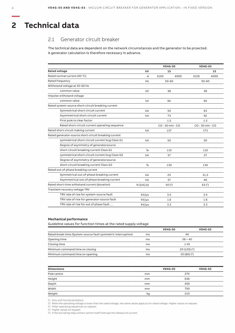
2.1 Generator circuit breaker
The technical data are dependent on the network circumstances and the generator to be proected. A generator calculation is therefore necessary in advance.
Mechanical performanceGuideline values for function times at the rated supply voltage
VD4G-50 VD4G-63
Rated break time (System-source fault symmetric interruption) ms 46
Opening time ms 28÷40
Closing time ms ≤55
Minimum command time on closing ms 20(120)(5)
Minimum command time on opening ms 20(80)(5)
Dimensions VD4G-50 VD4G-63
Pole centre mm 275
Height mm 636
Depth mm 459
Width mm 750
Weight kg 210
(1) Only with forced ventilation.(2) When the operating voltage is lower than the rated voltage, the same values apply as for rated voltage. Higher values on request. (3) Other operating sequences on request.(4) Higher values on request.(5) If the activating relay contact cannot itself interrupt the release coil current
VD4G-50 VD4G-63
Rated voltage kV 15 15
Ratednormalcurrent(40°C) A 3150 4000 3150 4000
Rated frequency Hz 50-60 50-60
Withstandvoltageat50-60Hz
common value kV 38 38
Impulse withstand voltage
common value kV 95 95
Rated system-source short-circuit breaking current
Symmetrical short-circuit current kA 50 63
Asymmetrical short-circuit current kA 73 92
First pole to clear factor 1.5 1.5
Rated short-circuit current operating sequence CO-30min-CO CO-30min-CO
Rated short-circuit making current kA 137 173
Rated generator-source short-circuit breaking current
symmetricalshort-circuitcurrentlscgClassG1 kA 50 50
Degree of asymmetry of generatorsource
short-circuitbreakingcurrentClassG1 % 110 110
symmetricalshort-circuitcurrentlscgClassG2 kA 37 37
Degree of asymmetry of generatorsource
short-circuitbreakingcurrentClassG2 % 130 130
Rated out-of-phase breaking current
Symmetrical out-of-phase breaking current kA 25 31,5
Asymmetrical out-of-phase breaking current kA 37 46
Rated short-time withstand current (duration) Ik [kA] (s) 50(4) 63(2)
Transient recovery voltage TRV
TRV rate of rise for system-source fault kV/µs 3.5 3.5
TRV rate of rise for generator-source fault kV/µs 1.6 1.6
TRV rate of rise for out of phase fault .... kV/µs 3.3 3.3
D IS TR I B U TI O N SO LU TI O NS 5
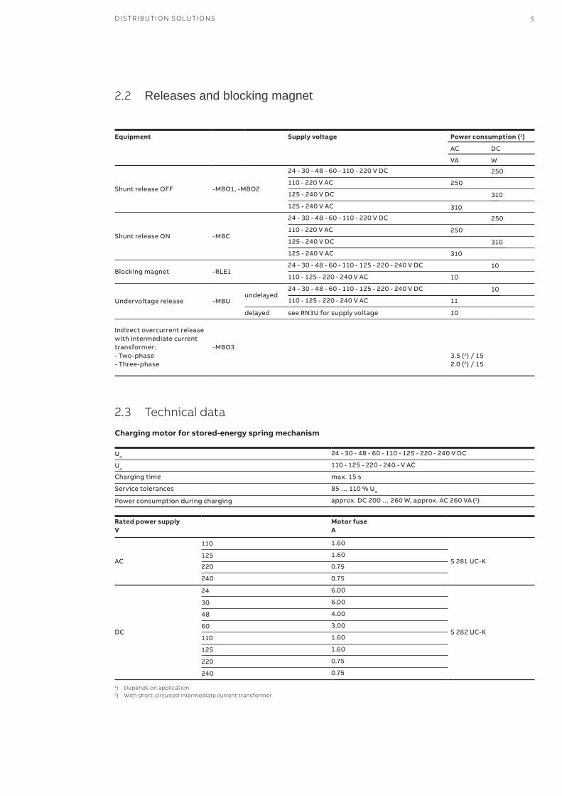
2.2 Releases and blocking magnet
Equipment Supply voltage Power consumption (1)
AC DC
VA W
Shunt release OFF -MBO1,-MBO2
24-30-48-60-110-220VDC
250
250
110-220VAC
125-240VDC
310
310
125-240VAC
Shunt release ON -MBC
24-30-48-60-110-220VDC
250
250
110-220VAC
125-240VDC
310
310
125-240VAC
Blocking magnet -RLE124-30-48-60-110-125-220-240VDC
10
10
110-125-220-240VAC
Undervoltage release -MBUundelayed
24-30-48-60-110-125-220-240VDC
11
10
110-125-220-240VAC
delayed seeRN3Uforsupplyvoltage 10
Indirect overcurrent release with intermediate current transformer:- Two-phase- Three-phase
-MBO33.5(2)/152.0(2)/15
2.3 Technical data
Charging motor for stored-energy spring mechanism
Ua24-30-48-60-110-125-220-240VDC
Ua110-125-220-240-VAC
Charging time max.15s
Service tolerances 85…110%Ua
Power consumption during charging approx.DC200…260W,approx.AC260VA (1)
Rated power supply V
Motor fuse A
AC
110 1.60
S281UC-K125 1.60
220 0.75
240 0.75
DC
24 6.00
S282UC-K
30 6.00
48 4.00
60 3.00
110 1.60
125 1.60
220 0.75
240 0.75
1) Depends on application2) With short-circuited intermediate current transformer
6 V D 4 G - 5 0 A N D V D 4 G - 6 3 - VAC U U M CI R C U IT B R E A K ER FO R G EN ER ATO R A PPL I C ATI O N – I N FI X ED V ER SI O N
—2 Technical data
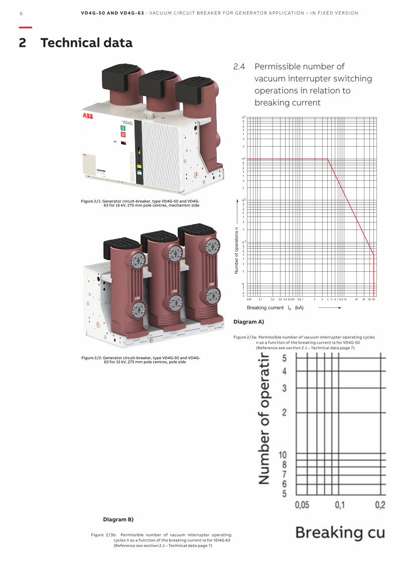
Figure 2/1: Generator circuit-breaker, type VD4G-50 and VD4G-63 for 15 kV, 275 mm pole centres, mechanism side
Figure 2/2: Generator circuit-breaker, type VD4G-50 and VD4G-63 for 15 kV, 275 mm pole centres, pole side
Figure 2/3a: Permissible number of vacuum interrupter operating cycles n as a function of the breaking current Ia for VD4G-50(Reference see section 2.1 – Technical data page 7)
2.4 Permissible number of vacuum interrupter switching operations in relation to breaking current
Diagram A)
Figure 2/3b: Permissible number of vacuum interrupter operatingcycles n as a function of the breaking current Ia for VD4G-63(Reference see section 2.1 – Technical data page 7)
Diagram B)
T
K
530
670
30
42,5
310
2
37,5
8
8 7
7,5
130 125
459
550
39 72
643
40°
80°
274
35 695
750
25 700 25
431
,5
275 275
750
10
0
434
4xM12
545
194 166
24
98
80 195 195MM
D IS TR I B U TI O N SO LU TI O NS 7
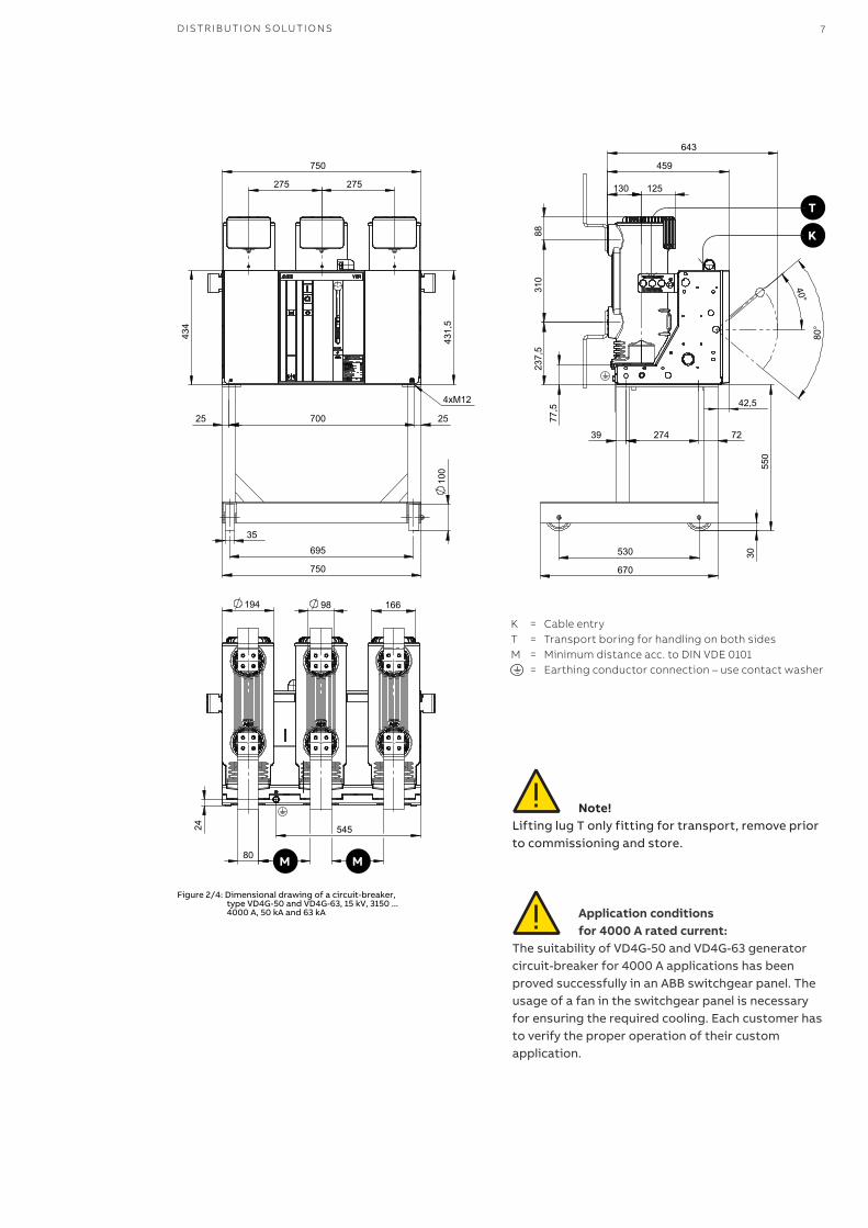
Note!Lifting lug T only fitting for transport, remove prior to commissioning and store.
Application conditionsfor 4000 A rated current:
The suitability of VD4G-50 and VD4G-63 generator circuit-breaker for 4000 A applications has been proved successfully in an ABB switchgear panel. The usage of a fan in the switchgear panel is necessary for ensuring the required cooling. Each customer has to verify the proper operation of their custom application.
Figure 2/4: Dimensional drawing of a circuit-breaker, type VD4G-50 and VD4G-63, 15 kV, 3150 ... 4000 A, 50 kA and 63 kA
K = Cable entryT = Transport boring for handling on both sidesM = Minimum distance acc. to DIN VDE 0101
= Earthing conductor connection – use contact washer
2 3 4
5
131 1.1
14
16.2
12
17
18
20
19
15
1 1.1 8 7 6
9
8 V D 4 G - 5 0 A N D V D 4 G - 6 3 - VAC U U M CI R C U IT B R E A K ER FO R G EN ER ATO R A PPL I C ATI O N – I N FI X ED V ER SI O N
—3 Structure and function
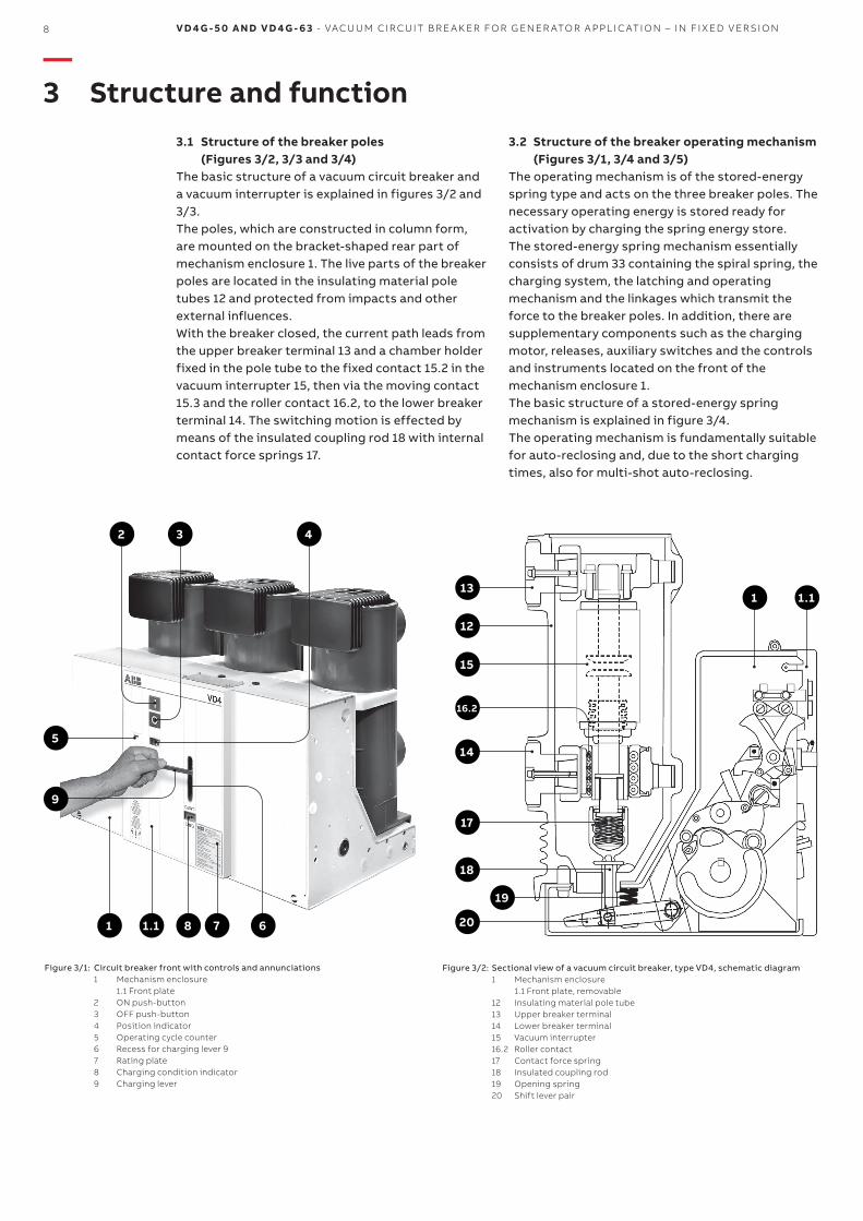
3.1 Structure of the breaker poles (Figures 3/2, 3/3 and 3/4)The basic structure of a vacuum circuit breaker and a vacuum interrupter is explained in figures 3/2 and 3/3. The poles, which are constructed in column form, are mounted on the bracket-shaped rear part of mechanism enclosure 1. The live parts of the breaker poles are located in the insulating material pole tubes 12 and protected from impacts and other external influences.With the breaker closed, the current path leads from the upper breaker terminal 13 and a chamber holder fixed in the pole tube to the fixed contact 15.2 in the vacuum interrupter 15, then via the moving contact 15.3 and the roller contact 16.2, to the lower breaker terminal 14. The switching motion is effected by means of the insulated coupling rod 18 with internal contact force springs 17.
3.2 Structure of the breaker operating mechanism (Figures 3/1, 3/4 and 3/5)The operating mechanism is of the stored-energy spring type and acts on the three breaker poles. The necessary operating energy is stored ready for activation by charging the spring energy store.The stored-energy spring mechanism essentially consists of drum 33 containing the spiral spring, the charging system, the latching and operating mechanism and the linkages which transmit the force to the breaker poles. In addition, there are supplementary components such as the charging motor, releases, auxiliary switches and the controls and instruments located on the front of the mechanism enclosure 1.The basic structure of a stored-energy spring mechanism is explained in figure 3/4.The operating mechanism is fundamentally suitable for auto-reclosing and, due to the short charging times, also for multi-shot auto-reclosing.
Figure 3/1: Circuit breaker front with controls and annunciations1 Mechanism enclosure
1.1 Front plate2 ON push-button3 OFF push-button4 Position indicator5 Operating cycle counter6 Recess for charging lever 97 Rating plate8 Charging condition indicator9 Charging lever
Figure 3/2: Sectional view of a vacuum circuit breaker, type VD4, schematic diagram1 Mechanism enclosure 1.1 Front plate, removable12 Insulating material pole tube13 Upper breaker terminal14 Lower breaker terminal15 Vacuum interrupter16.2 Roller contact17 Contact force spring18 Insulated coupling rod19 Opening spring20 Shift lever pair
15.2
15.3
15.7
15.1
15.4
15.6
15.5
15
15.3
15.2
17
19
20 21
6
34
33
33
5032
18
30
9
35
D IS TR I B U TI O N SO LU TI O NS 9
In the basic version of the circuit breaker, the spring energy store is charged manually. The operating mechanism can optionally be fitted with a charging motor. There is one rating plate with the main data of the switch equipment on front plate 1.1, and another at the lower front right in mechanism enclosure 1. The basic version of the stored-energy spring mechanism is fitted with the following auxiliary equipment:• Shunt release OFF -MBO1• Five-pole auxiliary switch -BGB2 for
annunciation purposes 38• Auxiliary switch -BGB4 for fault annunciation• Mechanical ON push-button 2• Mechanical OFF push-button 3• Mechanical position indicator 4• Charging condition indicator 8 for the spring
energy store• Mechanical operating cycle counter 5
The following additional equipment can be installed:• Blocking magnet -RLE1 with auxiliary switch -BGL1• Shunt release ON -MBC• Second shunt release OFF -MBO2• Indirect overcurrent release -MBO3• Undervoltage release -MBU• Five-pole auxiliary switches -BGB1 and -BGB3• Charging motor -MAS 36• Five-pole auxiliary switch -BGS1 to switch the
charging motor.
3.2.1 Releases, blocking magnet and auxiliary switches
(Figures 3/1, 3/5, 7/1, 7/2, 7/3 and 7/5)• The releases and the blocking magnet are
mounted at the top left on the spring operating mecha nism.
• The allocation of the auxiliary switches can be seen in the wiring diagram of figures 7/5, 7/6 and 7/7.
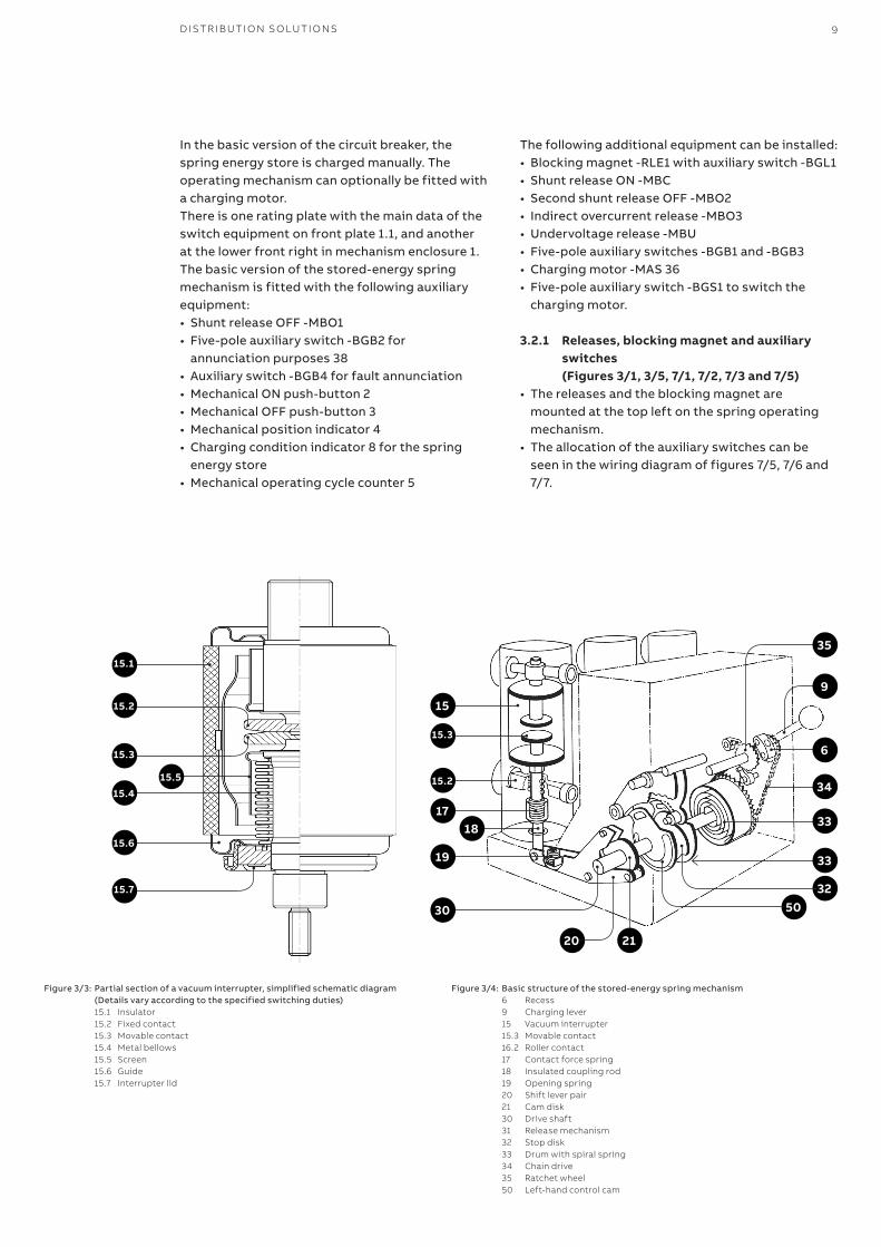
Figure 3/3: Partial section of a vacuum interrupter, simplified schematic diagram (Details vary according to the specified switching duties)15.1 Insulator15.2 Fixed contact15.3 Movable contact15.4 Metal bellows15.5 Screen15.6 Guide15.7 Interrupter lid
Figure 3/4: Basic structure of the stored-energy spring mechanism6 Recess9 Charging lever15 Vacuum interrupter15.3 Movable contact16.2 Roller contact17 Contact force spring18 Insulated coupling rod19 Opening spring20 Shift lever pair21 Cam disk30 Drive shaft31 Release mechanism32 Stop disk33 Drum with spiral spring34 Chain drive35 Ratchet wheel50 Left-hand control cam
36 31 6 34
37 35 38
10 V D 4 G - 5 0 A N D V D 4 G - 6 3 - VAC U U M CI R C U IT B R E A K ER FO R G EN ER ATO R A PPL I C ATI O N – I N FI X ED V ER SI O N
—3 Structure and function
• The five-pole auxiliary switch -BGS1 is operated by the charging condition indicator 8. It controls the charging motor -MAS, serves as an electrical interlock for shunt release ON -MBC when the spring mechanism is not sufficiently charged, and also provides an electrical switching readiness signal.
• Operation of the five-pole auxiliary switches -BGB1, -BGB2 and -BGB3 is dependent on the switching position of the circuit breaker.
• Auxiliary switch -BGB1 interrupts the circuit of the optional additional shunt release OFF -MBO2 with the circuit breaker in the open position, and the circuits of shunt release ON -MBC and the optional blocking magnet -RLE1 with the circuit breaker in the closed position. There is one further NOC for other purposes.
• On failure or absence of the control voltage, blocking magnet -RLE1 mechanically locks the ON half shaft and simultaneously acts on the corresponding auxiliary switch -BGL1 to interrupt the circuit of shunt release ON -MBC.
• Blocking magnet -RLE1 is accessible when front plate 1.1 is removed.
• Auxiliary switch -BGB2 interrupts the circuit of shunt release OFF -MBO2 with the circuit breaker in the open position. One further NOC and three NCCs are available for annunciation, control and interlock purposes.
• Auxiliary switch -BGB3 can be optionally designed with any possible combination of contacts from five NOCs to five NCCs. Its contacts are available for any required control, annunciation or interlock functions. The auxiliary switch is normally configured as shown in figures 7/5, 7/6 and 7/7.
• The single pole auxiliary switch -BGB4 (fleeting contacttime≥30ms)servestoprovideafaultsignal (“breaker released”).
With remote control, the auxiliary switch is necessarily operated by:• Shunt release OFF -MBO1 or• Shunt release OFF -MBO2 or• Undervoltage release -MBU or• Indirect overcurrent release -MBO3.
Note: 1. Shunt releases OFF (-MBO1) and ON (-MBC) are
exclusively provided for opening and closing in normal operation. For safety breaking operations, the second shunt release OFF (-MBO2) must be used, in most cases with a separate control voltage supply. These three releases are of the solenoid type and suitable for a large number of operating cycles.
2. The undervoltage release (-MBU) and/or indirect overcurrent release (-MBO3) are pure safety and protection releases and must not be used for switching in normal operation.
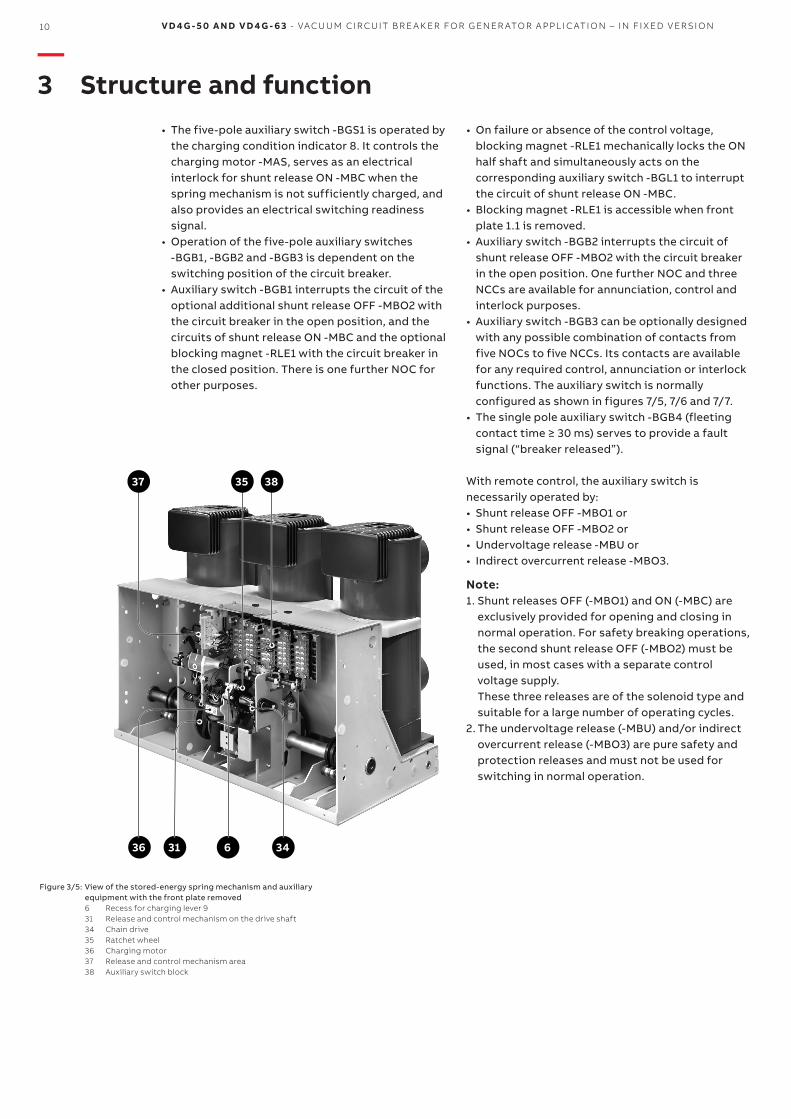
Figure 3/5: View of the stored-energy spring mechanism and auxiliary equipment with the front plate removed6 Recess for charging lever 931 Release and control mechanism on the drive shaft34 Chain drive35 Ratchet wheel36 Charging motor37 Release and control mechanism area38 Auxiliary switch block
D IS TR I B U TI O N SO LU TI O NS 11
3.3 Function
3.3.1 Charging of the spring energy store (Figures 3/1 and 3/4)
To provide the necessary motive energy, the spring energy store, either charged automatically by a charging motor or manually in a vertical pumping action with charging lever 9, depending on the equipment fitted to the circuit breaker. The current charging condition is shown at charging condition indicator 8. As a precondition for an auto-reclosing sequence, the operating mechanism is either (re-) charged after a closing operation automatically by the charging motor, or it requires (re-) charging by hand if the operating mechanism is of the manual type.
3.3.2 Closing procedure (Figures 3/1, 3/3, 3/4 and 3/5)The closing process is started by the mechanical ON push-button 2, or by activation of shunt re lease ON -MBC. The release mechanism 31 then permits drive shaft 30 to be rotated by the (previously) charged spiral spring. The moving contact 15.3 in vacuum interrupter 15 is moved until the contacts touch by cam disk 21 and further kinematic links. In the further sequence of motion, spring arrangement 17 is tensioned and the appropriate amount of contact force thus applied. The available overtravel is higher than the maximum value of contact erosion during lifetime of the interrupter. During the closing process, opening springs 19 are simultaneously tensioned.
3.3.3 Opening procedure (Figures 3/1, 3/3, 3/4 and 3/5)
The opening procedure is initiated by mechanical OFF push-button 3 or by activation of one of releases -MBO1, -MBU, -MBO3 or -MBO2. Observe the notes in section 3.2.1 on control of the releases. Release mechanism 31 then permits drive shaft 30 to be turned further by the spring energy store, which is still sufficiently charged. Opening spring 19, which is thus released, moves contact 15.3 into the open position at a defined speed.
3.3.4 Auto-reclosing sequenceAn OFF-ON or OFF-ON-OFF auto-reclosing sequence is activated and checked by the protection system. It is necessary for the spiral spring in the operating mechanism to be in the (re-)charged condition, with the circuit breaker in the closed position. The (re-)charging process is carried out automatically after closing of the breaker on breakers with motor charging mechanisms, but must be carried out manually on breakers without charging mo tors (or when the charging motor has broken down). Opening of the breaker is also possible during the (re-)charging process, but subsequent closing of the breaker is however blocked until the charging process has been completed.
3.3.5 Quenching principle of the vacuum interrupter
Due to the extremely low static interrupter chamber pressure of 10-2 to 10-6 Pa, only a relatively small contact gap is required to achieve a high dielectric strength. The arc is extinguished on one of the first natural current zeros.Due to the small contact gap and the high conductivity of the metal vapour plasma, the arc drop voltage, and additionally, due to the short arcing time, the associated arc energy, are extremely low, which has advantageous effects on the life of the contacts and thus on that of the vacuum interrupters.
3.2.2 Mounting of the VD4G-50 on trucks from other manufacturers
VD4G-50 generator circuit breakers which are not installed on ABB withdrawable parts must be fitted with one or two additional auxiliary switches which are dependent on the mechanical lock and release device. These must interrupt the circuit of shunt release ON -MBC.Similary to auxiliary switches -BGT2 and -BGT1 in ABB withdrawable parts, no electrial pulse may arrive during and before mechanical blocking of the spindle mechanism, and may only be applied again after the end of mechanical blocking.This ensures that the shunt release ON cannot be loaded with an electrical ON pulse when the withdrawable part is in an intermediate position, which could burn out the coil.
12 V D 4 G - 5 0 A N D V D 4 G - 6 3 - VAC U U M CI R C U IT B R E A K ER FO R G EN ER ATO R A PPL I C ATI O N – I N FI X ED V ER SI O N
4.1 Condition on delivery
The factory-assembled switching devices are checked at the works for completeness of the equipment installed and simultaneously subjected to a routine test in accordance with VDE 0670, part 1000, or IEC publication 62271-1, thus verifying their correct structure and function.
4.2 PackagingThe switching devices are mounted individually on a wooden pallet and sealed in film and/or packed in cardboard for delivery.
Packaging for overseas shipment:• Drying agent bags inserted in the film-sealed
packaging• Drying agent bags in accordance with DIN 55 473.
4.3 TransportLoading of the package units must only be carried out with a • crane, • fork-lift truck and/or• trolley jack.
Note:• Avoid impact during handling.• Do not subject to other damaging mechanical
stresses.• Lifting gear must not be attached to the breaker
poles or parts of the operating mechanism. Use the lifting lugs 1.3 for hoists (Figure 6/1).
4.4 DeliveryThe duties of the consignee on receipt of the switching devices at site include the following:• Checking the delivery for completeness and
freedom from damage (e.g. moisture and its adverse effects).
• Any short quantities, defects or damage in transit: - Must be precisely documented on the
consignment note. - The shipper/carrier is to be notified immediately
in accordance with the liability provisions of the German general conditions for forwarders (ADSp/KVO).
Note:Always take photographs to document any major damage.
—4 Despatch and storage
4.5 Intermediate storage
Intermediate storage of the switching device in the switch position OFF and the stored-energy spring mechanisms discharged
Indicator DISCHARGED:
Conditions for optimum intermediate storage:
1. Devices with basic packaging or unpacked:• A dry and well ventilated storeroom with climate in
accordance with VDE 0670, part 1000 / IEC 60694 / IEC62271-1.
• Room temperature which does not fall below –5 °C.
• Do not remove or damage the packaging.• Unpackaged devices:
- Are to be loosely covered with protective sheeting.
- Sufficient air circulation must be maintained.• Check regularly for any condensation.
2. Devices with seaworthy or similar packaging with internal protective sheeting:
• Store the transport units: - protected from the weather, - dry, - safe from damage.
• Check the packaging for damage.• If the maximum storage period starting from the
date of packaging has been exceeded: - The protective function of the packaging is no
longer guaranteed. - Suitable action must be taken if inter-mediate
storage is to continue.
D IS TR I B U TI O N SO LU TI O NS 13
—5 Installation
Careful and professional installation of the switching device is one of the fundamental conditions of trouble-free circuit breaker operation.• Install the mechanism enclosure in the panel
without tension or distortion, inserting dished washers below the nuts or bolt heads at each of the four mounting points (dependent on the order).
• Connect the main terminals without any permanent tension or pressure forces, exerted for example by the conductor bars.
• When connecting the conductor bars, the bolts must be inserted to the depth shown on the dimensional drawing.
• Take account of any tested terminal zone.• Use DIN bolts of tensile class 8.8, fastening
conductor bars together with dished washers.• Make a short-circuit proof connection between the
PE conductor and the main earthing bar in the switchgear, using contact washers.
• Remove any dirt. See also section 7.3.1.
(1) • Rated tigthening torques for fasteners without lubrication are based on the thread friction coefficient 0.14 (the actual values of which are subject to unavoidable, in some cases not insignificant, spread).
• Rated tigthening torques for fastener with lubrication in accordance with DIN 43673.
(2) Thread and contact face of head lubricated. Take account of any tightening torques which deviate from the general
table (e.g. for contact systems or device terminals) as stated in the detailed technical documentation.
It is recommended that the threads or head contact surfaces of the bolts be lightly oiled or greased, so as to achieve a precisely defined rated tightening torque.
Recommended rated tightening torque (1)Nm
Thread sizeLubricant (2)
without (dry) Oil or grease
M 6 10.5 4.5
M 8 26 10
M 10 50 20
M 12 86 40
M 16 200 80
14 V D 4 G - 5 0 A N D V D 4 G - 6 3 - VAC U U M CI R C U IT B R E A K ER FO R G EN ER ATO R A PPL I C ATI O N – I N FI X ED V ER SI O N
—6 Commissioning / Operation
6.1 Note on safety at work
• This switching device may only be operated by speciallytrained personnel who are familiar with the characteristics ofthe particular device.
• Observe the relevant instructions in section 1.2.• Due to safety reasons, the circuit breaker has to be treated as
“switched on” if the switching position can not clearlydetermined.In this case all high voltage connections to the breaker have tobe de-energized and zero potential on the primary side of thebreaker has to be confirmed prior to commissioning,operation, maintenance or repair work.
6.2 Preparatory activities(Prior to application of primary voltage)
• Check the circuit breaker for any kind of damage or otherinjurious environmental influence, and restore to the propercondition where necessary.
• Remove any contamination, particularly on insulating parts,which has occurred during transit, storage or installation.
• Check the primary and secondary connections and theprotective conductor terminal.
• Charge the spring energy store by hand (see section 6.3.1).• Perform a trial opening or closing operation of the circuit
breaker using push-button 2 or 3 (taking into account anyrequired supply voltage and any relevant interlocks).
• Check the charging motor on circuit breakers with motor-operated mechanisms by applying supply voltage.
• Ensure that the Instruction Manual is available to theoperators at all times.
• Remove the lifting lugs 1.3 for hoists (Figure 6/1).
6.3 Operation of the circuit breaker
6.3.1 Charging the spring energy storeCircuit breakers with charging motors:• Charging takes place automatically.• If the charging motor breaks down, the charging process can
be carried out completed manually.
Circuit breakers with manual charging mechanisms:• Insert charging lever 9 into recess 6 and pump up and down
for approx. 25 strokes until the charged condition isdisplayed.
• When the charged condition is reached, the chargingmechanism automatically disengag es, and further strokes ofthe charging lever have no effect.
Key to the charging condition indications:
Discharged Charged
As a precondition for an auto-reclosing sequence, the operating mechanism is either (re-)charged after a clos ing operation automatically by the charging motor, or it requires (re-)charging by hand if the operating mechanism is of the manual type.
6.3.2 Closing and opening• Closing:
Press mechanical ON push-button 2, or operatethe electrical control unit.
• Opening:Press mechanical OFF push-button 3, or operatethe electrical control unit.
Observe the notes in section 3.2.1.
The operating cycle counter 5 is automaticallyincremented by one complete figure with eachswitching cycle. On completion of a switchingoperation the position indicator 4 in the windowof front plate 1.1 shows the appropriate positionof the circuit breaker.
• Anti-pumping relay:The anti-pumping relay -KFN (wiring diagram infigures 7/5, 7/6 and 7/7) prevents repeated ON-OFF switching operations if, for example, thebreaker is tripped by a protection relay inresponse to a primary side fault while apermanent electrical closing command issimultaneously applied. The circuit breaker canthen only be closed after the closing commandhas been interrupted.
• Closing on failure of supply voltage: - With standard equipment:
On failure of the control voltage, mechanical closing by means of ON push-button 2 is possible at any time.
- With blocking magnet -RLE1 fitted: On failure of the control voltage, blocking magnet -RLE1 mechanically locks the ON haflshaft and simultaneously interrupts the circuit shunt release ON -MBC via the cor-responding auxiliary switch -BGL1.
• Closing with the blocking magnet de-energisedrequires manipulation of the circuit breakeroperating mechanism: - Remove front plate 1.1. - Take care to avoid rotating parts!
2 3 4
5
8 1.3
9
D IS TR I B U TI O N SO LU TI O NS 15
• Opening on failure of supply voltage: On failure of the supply voltage, mechanical
opening by means of OFF push-button 3 is possible at any time.
6.3.3 Run-on blockWhen any irregularities occur in the internal control mechanism or with the charging function of the spring energy store, the run-on stop blocks the next closing operation.This is a protective function to prevent damage to the circuit breaker.
Release of the run-on block may only be performed by servicing personnel from ABB or adequately trained specialist stuff.
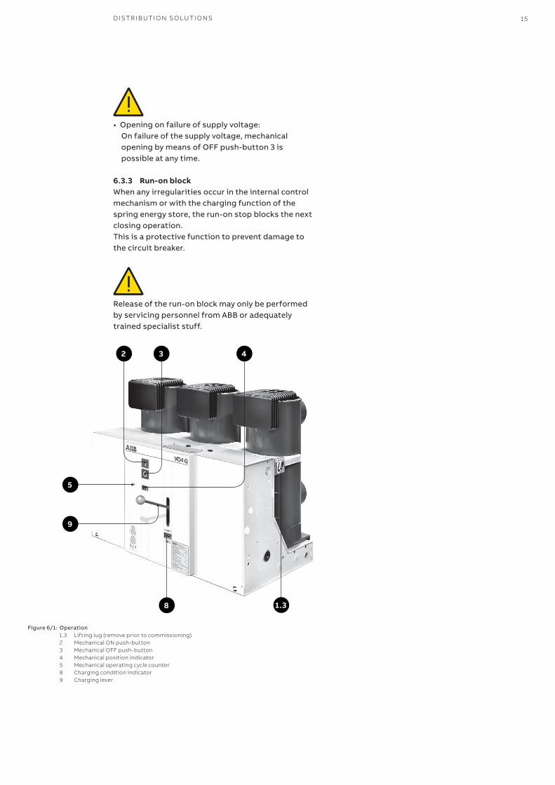
Figure 6/1: Operation1.3 Lifting lug (remove prior to commissioning)2 Mechanical ON push-button3 Mechanical OFF push-button4 Mechanical position indicator5 Mechanical operating cycle counter8 Charging condition indicator 9 Charging lever
16 V D 4 G - 5 0 A N D V D 4 G - 6 3 - VAC U U M CI R C U IT B R E A K ER FO R G EN ER ATO R A PPL I C ATI O N – I N FI X ED V ER SI O N
—7 Maintenance
Maintenance serves to ensure trouble-free operation and achieve the longest possible working life of the switchgear.In accordance with DIN 31051 / IEC 61208 / IEC 62271-1 it comprises the following closely related activities:
Inspection: Determination of the actual condition
Servicing: Preservation of a functional condition
Repair: Measures to restore the functional condition.
7.1 GeneralVacuum circuit breakers are characterized by their simple and robust construction. They have a long life expectancy. Their operating mechanisms have a low maintenance requirement, and the interrupters are maintenance-free during their working life. There is no adverse effect on the vacuum, even from frequent switching of operating and short-circuit currents.The servicing intervals and scope are determined by environmental influences, the switching sequen ces and number of short-circuit breaking operations.
Note:The following must be observed for all maintenance work:• The relevant specifications in section 1.2.2• Notes on safety at work in section 6.1• Standards and specifications in the country of
installation.
Maintenance work may only be performed by fully trained personnel, observing all the relevant safety regulations. It is recommended that ABB after-sales service personnel should be called in, at least during the performance of servicing and repair work.While the work is in progress, all supply voltage sources must also be disconnected and secured to prevent reconnection.
Note:In order to prevent accidents (particularly injury to hands!) extreme care should be taken during all repair work on the operating mechanism, especially with front plate removed.
The spiral spring in the spring energy store, for instance, retains a basic tension which is independent of the charging and discharging processes during switching, so as to ensure correct function. This spring energy can be inadvertently released if work is performed incorrectly on the spring mechanism!
7.1.1 Service lifeTypical life expectancies for VD4G-50 and VD4G-63 Generator circuit-breakers: • The maintenance-free vacuum interrupters up to
10,000 operating cycles (see section 2.4 figure2/2).
• The breaker itself, depending on presupposingcarefully performed inspection and servicing workand normal operating conditions, up to 3,000operating cycles.
The service life data fundamentally apply to allcomponents which are not directly influenced by theoperator.Components operated manually (movement of thewithdrawable part, etc.) may deviate.
7.2 Inspection and functionaltesting
7.2.1 Switching devices in general• The proper condition of the switching device is to
be verified by regular inspection.• The checks are to be performed in accordance
with BGV A3 standard. If further standards exist inthe country of installation they shall be consideredin the checks.
• Inspection at fixed intervals may be waived if theswitchgear is permanently monitored by aqualified personnel.
• The checks first and foremost comprise visualexamination for contamination, corrosion,moisture and discharge phenomena.
• In unusual operating conditions (including adverseclimatic conditions) and/or special environmentalpollutions (e.g. heavy contamination andaggressive atmosphere), inspection may also benecessary at shorter intervals.
• If an incorrect condition is found, appropriateservicing measures are to be initiated.
7.2.2 Stored-energy spring mechanism (Figures 7/1 to 7/4)
Functional testing of the operating mechanism is to e performed for the generator circuit breaker: Breakers with rated short-circuit breaking current with 50 kA and 63 kA: • after 3,000 operating cycles or 5 years or• during servicing work as set out in 7.2.1.Prior to functional testing, switch the breaker offand isolate the outgoing feeder.
Note:Isolate and secure the working area in accordancewith the safety regulations specified by DIN VDE/IEC.
D IS TR I B U TI O N SO LU TI O NS 17
Observe the safety regulations.
Details of the servicing:• Switch off the charging motor (if fitted), and
discharge the spring energy store by closing and opening the breaker once.
• Replace parts subject to high climatic and mechanical stresses as a precaution.
• For replacing highly stressed parts neutralize basic tension of the spiral spring, state the rate. Be careful when carrying out!
• Relubricate pawls, support shafts, sliding and rotating bearing surfaces. Lubri cant: Isoflex Topas NB 52.
• Check the fit of fasteners (e.g. locking pins) in cranks, pins, bolts etc. Check the tightness of fastening bolts.
• Always replace any spring lock washers, split pins and other fasteners removed during the work with new parts when reassembling the equipment.
• Check the general condition of the operating mechanism and recharge the spring energy store.
• Perform comprehensive mechanical and electrical functional tests.
• Observe the instructions on setting.• Ensure that the bolted joints at the contact
locations of the conductor bar system and the earthing connections are tight.
Note:Above mentioned work may only be performed by the after-sales service personnel of ABB or adequately qualified personnel.
7.3.3 Breaker poleThe breaker pole with the vacuum interrupter is maintenance-free up to reaching the permissible number of vacuum interrupter operating cycles in accordance with section 2.4.Checking of the vacuum is only necessary when there is good cause to suspect that force applied externally to a pole tube has caused damage to the vacuum interrupter inside.If the pole tube is damaged or destroyed, it may be necessary to replace the complete breaker pole.The working life of the vacuum interrupter is defined by the sum current limit corresponding to the equipment data in individual cases in accordance with section 2.4:• When the sum current limit is reached, the
complete breaker poles are to be replaced.
Scope of functional testing:• Perform several switching operations under no
load, above all with circuit breakers seldomoperated in normal service.
• Switch off the charging motor (if fitted) anddischarge the spring energy store by ON/OFFswitching operations.
• Examine visual the condition of the lubrication onrotary bearings, sliding surfaces, etc.
• Check the proper mechanical/electrical sequenceof the individual functions.
7.2.3 Breaker poleNo inspection of the breaker pole above and beyondthe stipulations of section 7.2.1 is necessary.
7.3 Servicing7.3.1 Switching devices in generalIf cleaning is found to be necessary duringinspections as set out in 7.2.1, the followingprocedure is to be adopted:• Prior to cleaning, the working area is to be isolated
and secured against reclosing where necessary inaccordance with the safety regulations of DINVDE/IEC.
• Cleaning of surfaces in general:- Dry, lightly adhering dust deposits with a soft,
dry cloth.- More strongly adhering contamination with
slightly alkaline household cleanser orIsopropanol.
• Cleaning of the insulating material surfaces andconductive components:- Light contamination: with Isopropanol.
Wipe down after cleaning, using clean water, and dryproperly.
Note:Use only halogen free cleansers, and in no case1.1.1-trichloroethane, trichloroethylene or carbontetrachloride!
7.3.2 Stored-energy spring mechanism(Figures 7/1 to 7/4)
Servicing of the operating mechanism is to beperformed after the following number of operatingcycles:• Breakers with rated short-circuit breaking currents up to 50 kA and 63 kA after 3,000 operating cycles. Prior to servicing, switch the breaker off, and
• move it out of the panel (with withdrawablebreakers) or
• isolate the outgoing feeder (with stationarymounted breakers).
18 V D 4 G - 5 0 A N D V D 4 G - 6 3 - VAC U U M CI R C U IT B R E A K ER FO R G EN ER ATO R A PPL I C ATI O N – I N FI X ED V ER SI O N
—7 Maintenance
Note:Dismantling and Replacement of the complete breaker poles should only be carried out by ABB after-sales service personnel or by specially trained personnel, particularly as proper ad just ment is necessary.
For testing the vacuum without dismantling the circuit breaker you may use:• Vakuumtester VIDAR, der Firma Programma
Electric GmbH Bad Homburg v. d. H.
The following test values have to be set for checking of the internal interrupter chamber pressure with the VIDAR vacuum tester:
Rated voltage of the circuit breaker DC test voltage
15kV 40kV
Testing is to be performed at the rated contact distance in the OFF condition.
Procedure for vacuum interrupter testing for stationary mounted switching devices:• Isolate and secure the working area in accordance
with the Safety Regulations to DIN VDE / IEC.• Open the VD4G-50 generator circuit breaker.• Earth all poles of the VD4G-50 generator circuit
breaker on one side.• Connect the earthed test lead of the the VIDAR
vacuum checker conductively to the station earth.• Connect the high voltage test lead of the VIDAR
vacuum checker with phase L1 of the unearthed pole side and test the vacuum interrupter chamber with the circuit breaker contact gap open. Repeat for phases L2 and L3.
Note:Connected cables may lead to a “detective” indication on the vacuum checker as a result of their cable capacitance. In such cases, the cables are not be removed.
7.4 Repair
7.4.1 Replacement of circuit breaker parts and accesso ries
Only remove and reassemble circuit breaker parts and accessories when the breaker has been switched off and the working area is to be isolated and secured against reclosing. The spring energy store must be discharged.
All supply voltage sources must be disconnect ed and secured against reclosing during the removal and installation work.
7.4.2 Touch up of surfaces• Sheet steel parts, painted:
- Remove rust, e.g. with a wire brush. - Grind off paint coat and grease. - Apply anti-rust primer and top coat. - Use top coat paint in the standard colour RAL
7035. • Sheet steel parts, with zinc surface and passivated
functional parts: - Remove white rust with a wire brush or cleaning
pad (e.g. Scotch-Brite white). - Remove loosely adhering particles with a dry
cloth. - Apply zinc spray or zinc dust primer.
• Functional parts, phosphated: - Remove rust with a wire brush or cleaning pad
(e.g. Scotch-Brite white). - Clean with a dry cloth. - Grease with Isoflex Topas NB 52.
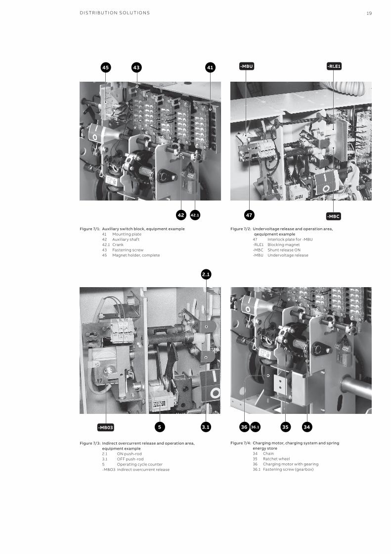
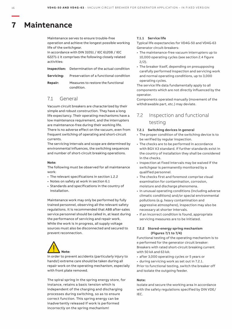
Figure 7/1: Auxiliary switch block, equipment example41 Mounting plate42 Auxiliary shaft42.1 Crank43 Fastening screw45 Magnet holder, complete
Figure 7/2: Undervoltage release and operation area, qequipment example47 Interlock plate for -MBU-RLE1 Blocking magnet-MBC Shunt release ON -MBU Undervoltage release
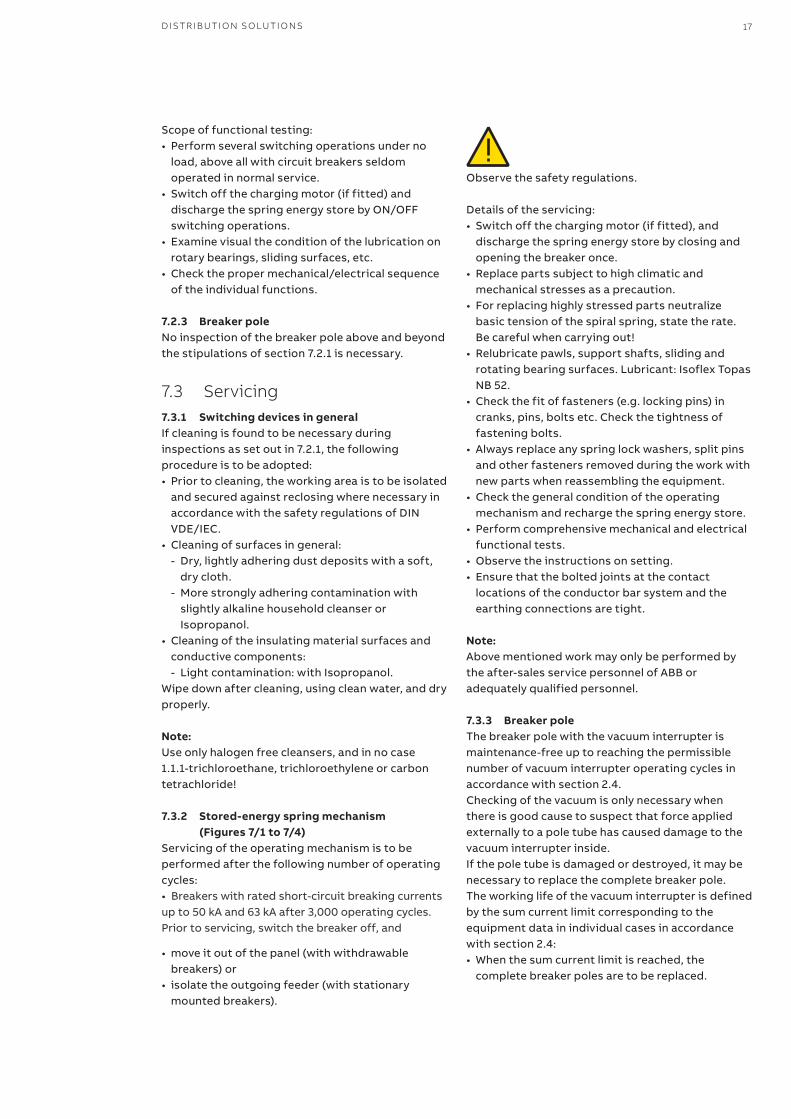
Figure 7/3: Indirect overcurrent release and operation area, equipment example
2.1 ON push-rod3.1 OFF push-rod5 Operating cycle counter -MBO3 Indirect overcurrent release
Figure 7/4: Charging motor, charging system and spring energy store
34 Chain35 Ratchet wheel36 Charging motor with gearing36.1 Fastening screw (gearbox)
-RLE1-MBU
-MBC4742.1
36.1
42
2.1
3.15
4345 41
-MB03 36 35 34
D IS TR I B U TI O N SO LU TI O NS 19
T
ype
19
Typ
e 20
T
ype
22
Typ
e 23
T
ype
24
•1 w
ith
ou
t -B
GL
1
20 V D 4 G - 5 0 A N D V D 4 G - 6 3 - VAC U U M CI R C U IT B R E A K ER FO R G EN ER ATO R A PPL I C ATI O N – I N FI X ED V ER SI O N
—7 Maintenance
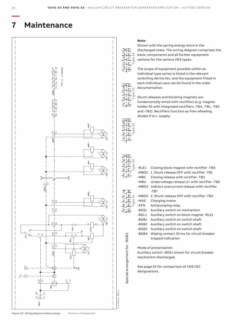
Note:Shown with the spring energy store in the discharged state. The wiring diagram comprises the basic components and all further equipment options for the various VD4 types.
The scope of equipment possible within an individual type series is listed in the relevant switching device list, and the equipment fitted in each individual case can be found in the order documentation.
Shunt releases and blocking magnets are fundamentally wired with rectifiers (e.g. magnet holder 45 with integrated rectifiers -TB4, -TB1, -TB3 and -TB2). Rectifiers function as free-wheeling diodes if d.c.-supply.
Sp
ecia
l arr
ang
emen
t fo
r: -
BG
B3:
-RLE1 Closing block magnet with rectifier -TB4-MBO1 1. Shunt release OFF with rectifier -TB1-MBC Closing release with rectifier -TB3-MBU Undervoltage release U< with rectifier -TB6-MBO3 Indirect overcurrent release with rectifier
-TB7-MBO2 2. Shunt release OFF with rectifier -TB2-MAS Charging motor-KFN Antipumping relay-BGS1 Auxiliary switch on mechanism-BGL1 Auxiliary switch on block magnet -RLE1-BGB1 Auxiliary switch on switch shaft-BGB2 Auxiliary switch on switch shaft-BGB3 Auxiliary switch on switch shaft-BGB4 Wiping contact 35 ms for circuit breaker
tripped indication
Mode of presentation:Auxiliary switch -BGS1 shown for circuit breaker mechanism discharged.
See page 25 for comparison of VDE/IEC designations.
Figure 7/5: Wiring diagram (without plug) Maximum of equipment
T
ype
19
Typ
e 20
T
ype
22
Typ
e 23
T
ype
24
•1 w
ith
ou
t -B
GL
1
D IS TR I B U TI O N SO LU TI O NS 21
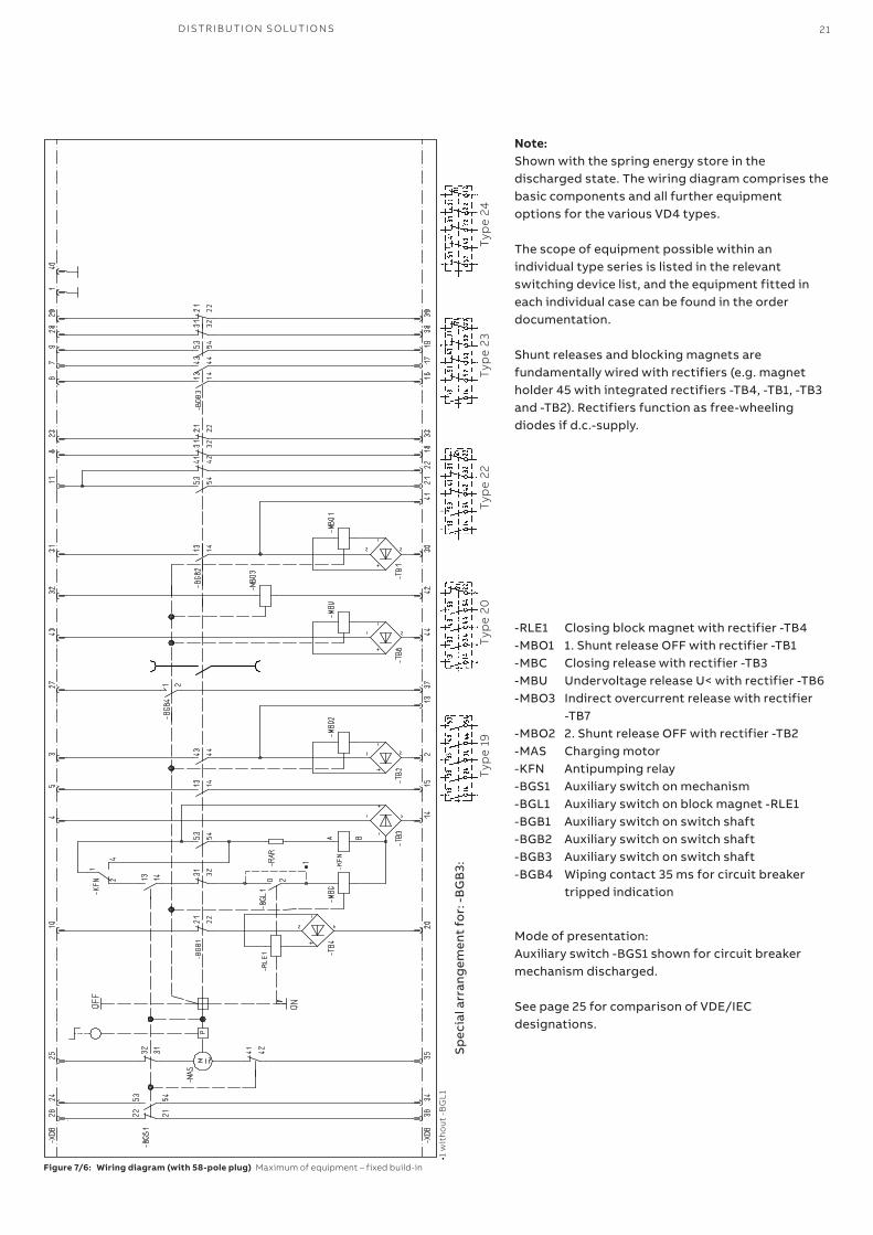
-RLE1 Closing block magnet with rectifier -TB4-MBO1 1. Shunt release OFF with rectifier -TB1-MBC Closing release with rectifier -TB3-MBU Undervoltage release U< with rectifier -TB6-MBO3 Indirect overcurrent release with rectifier
-TB7-MBO2 2. Shunt release OFF with rectifier -TB2-MAS Charging motor-KFN Antipumping relay-BGS1 Auxiliary switch on mechanism-BGL1 Auxiliary switch on block magnet -RLE1-BGB1 Auxiliary switch on switch shaft-BGB2 Auxiliary switch on switch shaft-BGB3 Auxiliary switch on switch shaft-BGB4 Wiping contact 35 ms for circuit breaker
tripped indication
Mode of presentation:Auxiliary switch -BGS1 shown for circuit breaker mechanism discharged.
See page 25 for comparison of VDE/IEC designations.
Figure 7/6: Wiring diagram (with 58-pole plug) Maximum of equipment – fixed build-in
Note:Shown with the spring energy store in the discharged state. The wiring diagram comprises the basic components and all further equipment options for the various VD4 types.
The scope of equipment possible within an individual type series is listed in the relevant switching device list, and the equipment fitted in each individual case can be found in the order documentation.
Shunt releases and blocking magnets are fundamentally wired with rectifiers (e.g. magnet holder 45 with integrated rectifiers -TB4, -TB1, -TB3 and -TB2). Rectifiers function as free-wheeling diodes if d.c.-supply.
Sp
ecia
l arr
ang
emen
t fo
r: -
BG
B3:
T
ype
19
Typ
e 20
T
ype
22
Typ
e 23
T
ype
24
•1 w
ith
ou
t -B
GL
1
22 V D 4 G - 5 0 A N D V D 4 G - 6 3 - VAC U U M CI R C U IT B R E A K ER FO R G EN ER ATO R A PPL I C ATI O N – I N FI X ED V ER SI O N
—7 Maintenance
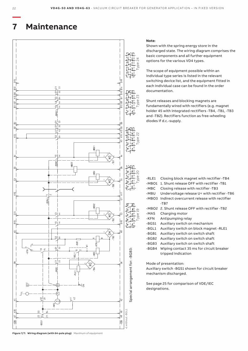
-RLE1 Closing block magnet with rectifier -TB4-MBO1 1. Shunt release OFF with rectifier -TB1-MBC Closing release with rectifier -TB3-MBU Undervoltage release U< with rectifier -TB6-MBO3 Indirect overcurrent release with rectifier
-TB7-MBO2 2. Shunt release OFF with rectifier -TB2-MAS Charging motor-KFN Antipumping relay-BGS1 Auxiliary switch on mechanism-BGL1 Auxiliary switch on block magnet -RLE1-BGB1 Auxiliary switch on switch shaft-BGB2 Auxiliary switch on switch shaft-BGB3 Auxiliary switch on switch shaft-BGB4 Wiping contact 35 ms for circuit breaker
tripped indication
Mode of presentation:Auxiliary switch -BGS1 shown for circuit breaker mechanism discharged.
See page 25 for comparison of VDE/IEC designations.
Note:Shown with the spring energy store in the discharged state. The wiring diagram comprises the basic components and all further equipment options for the various VD4 types.
The scope of equipment possible within an individual type series is listed in the relevant switching device list, and the equipment fitted in each individual case can be found in the order documentation.
Shunt releases and blocking magnets are fundamentally wired with rectifiers (e.g. magnet holder 45 with integrated rectifiers -TB4, -TB1, -TB3 and -TB2). Rectifiers function as free-wheeling diodes if d.c.-supply.
Figure 7/7: Wiring diagram (with 64-pole plug) Maximum of equipment
Sp
ecia
l arr
ang
emen
t fo
r: -
BG
B3:
D IS TR I B U TI O N SO LU TI O NS 23
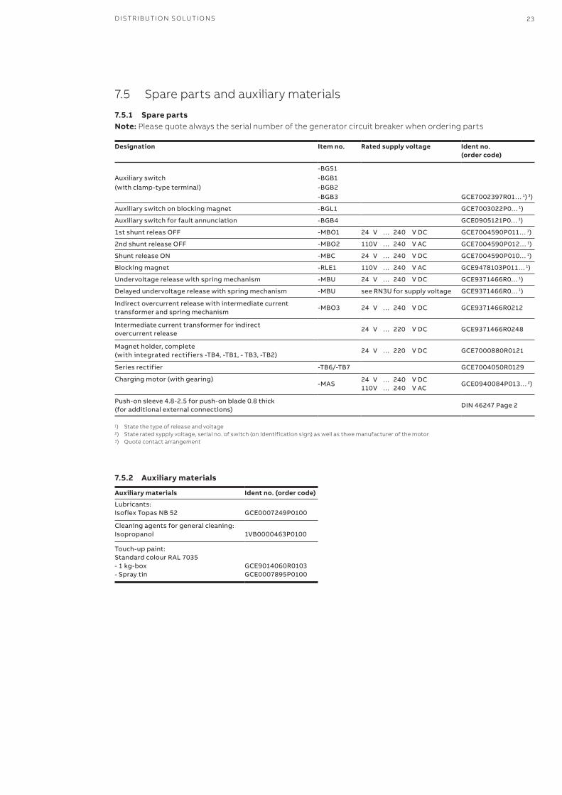
7.5 Spare parts and auxiliary materials
7.5.1 Spare partsNote: Please quote always the serial number of the generator circuit breaker when ordering parts
Auxiliary materials Ident no. (order code)
Lubricants: IsoflexTopasNB52 GCE0007249P0100
Cleaning agents for general cleaning: Isopropanol 1VB0000463P0100
Touch-up paint:StandardcolourRAL7035-1kg-box- Spray tin
GCE9014060R0103GCE0007895P0100
Designation Item no. Rated supply voltage Ident no. (order code)
Auxiliary switch (with clamp-type terminal)
-BGS1-BGB1-BGB2-BGB3 GCE7002397R01…1)3)
Auxiliary switch on blocking magnet -BGL1 GCE7003022P0…1)
Auxiliary switch for fault annunciation -BGB4 GCE0905121P0…1)
1stshuntreleasOFF -MBO1 24 V … 240 VDC GCE7004590P011…1)
2ndshuntreleaseOFF -MBO2 110V … 240 VAC GCE7004590P012…1)
Shunt release ON -MBC 24 V … 240 VDC GCE7004590P010…1)
Blocking magnet -RLE1 110V … 240 VAC GCE9478103P011…1)
Undervoltage release with spring mechanism -MBU 24 V … 240 VDC GCE9371466R0…1)
Delayed undervoltage release with spring mechanism -MBU seeRN3Uforsupplyvoltage GCE9371466R0…1)
Indirect overcurrent release with intermediate current transformer and spring mechanism
-MBO3 24 V … 240 VDC GCE9371466R0212
Intermediate current transformer for indirect overcurrent release
24 V … 220 VDC GCE9371466R0248
Magnet holder, complete (withintegratedrectifiers-TB4,-TB1,-TB3,-TB2)
24 V … 220 VDC GCE7000880R0121
Series rectifier -TB6/-TB7 GCE7004050R0129
Charging motor (with gearing)-MAS
24 V … 240 VDC110V … 240 VAC
GCE0940084P013…2)
Push-onsleeve4.8-2.5forpush-onblade0.8thick(for additional external connections)
DIN46247Page2
7.5.2 Auxiliary materials
1) State the type of release and voltage2) State rated sypply voltage, serial no. of switch (on identification sign) as well as thwe manufacturer of the motor3) Quote contact arrangement
24 V D 4 G - 5 0 A N D V D 4 G - 6 3 - VAC U U M CI R C U IT B R E A K ER FO R G EN ER ATO R A PPL I C ATI O N – I N FI X ED V ER SI O N
—8 Application of the X-ray regulations
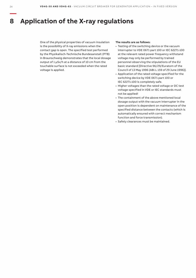
One of the physical properties of vacuum insulation is the possibility of X-ray emissions when the contact gap is open. The specified test performed by the Physikalisch-Technische Bundesanstalt (PTB) in Braunschweig demonstrates that the local dosage output of 1 µSv/h at a distance of 10 cm from the touchable surface is not exceeded when the rated voltage is applied.
The results are as follows:• Testing of the switching device or the vacuum
interrupter to VDE 0671 part 100 or IEC 62271-100 at the relevant rated power frequency withstand voltage may only be performed by trained personnel observing the stipulations of the EU basic standard [Directive 96/29/Euratom of the Council of 13 May 1996 (ABI.L 159 of 29 June 1996)].
• Application of the rated voltage specified for the switching device by VDE 0671 part 100 or IEC 62271-100 is completely safe.
• Higher voltages than the rated voltage or DC test voltage specified in VDE or IEC standards must not be applied!
• The containment of the above mentioned local dosage output with the vacuum interrupter in the open position is dependent on maintenance of the specified distance between the contacts (which is automatically ensured with correct mechanism function and force transmission).
• Safety clearances must be maintained.
D IS TR I B U TI O N SO LU TI O NS 25
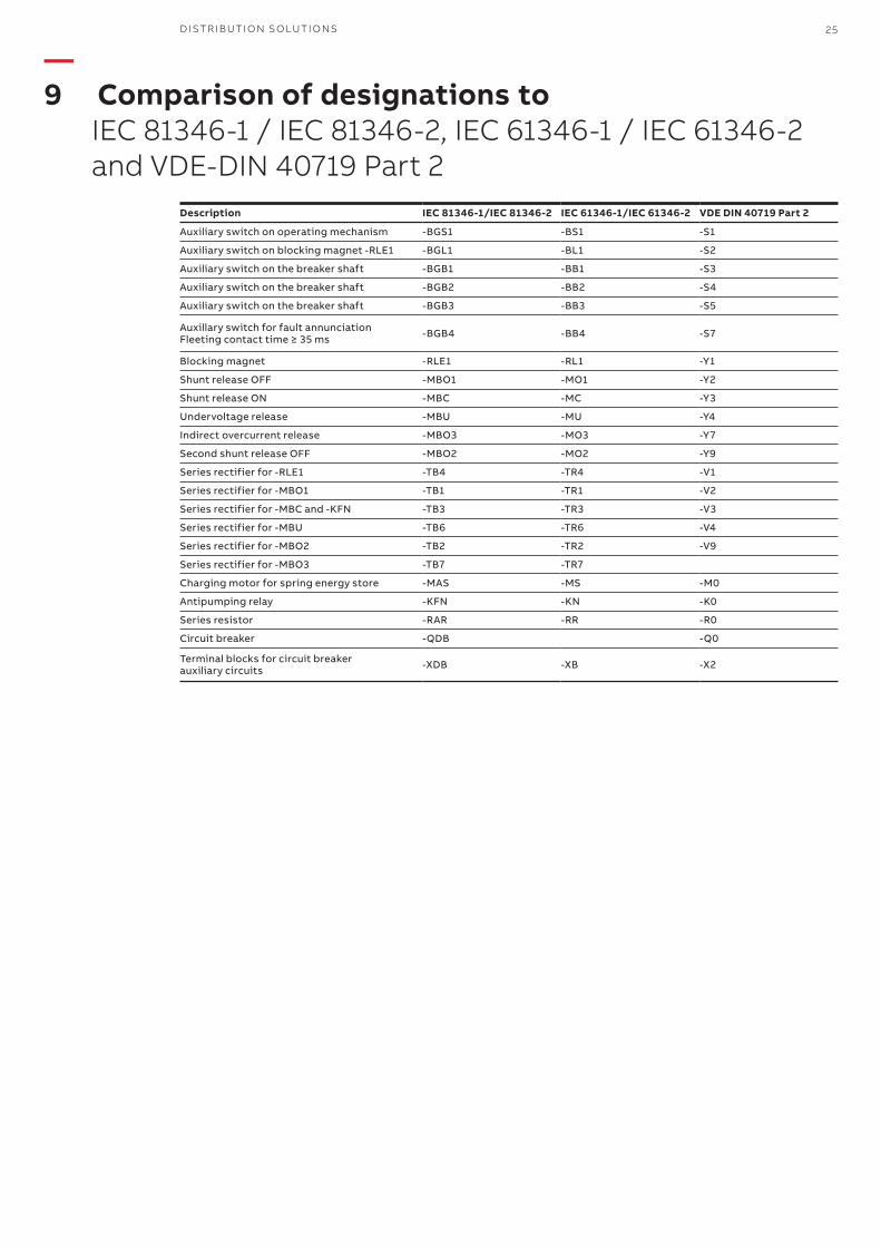
—9 Comparison of designations to IEC 81346-1 / IEC 81346-2, IEC 61346-1 / IEC 61346-2 and VDE-DIN 40719 Part 2
Description IEC 81346-1/IEC 81346-2 IEC 61346-1/IEC 61346-2 VDE DIN 40719 Part 2
Auxiliary switch on operating mechanism -BGS1 -BS1 -S1
Auxiliaryswitchonblockingmagnet-RLE1 -BGL1 -BL1 -S2
Auxiliary switch on the breaker shaft -BGB1 -BB1 -S3
Auxiliary switch on the breaker shaft -BGB2 -BB2 -S4
Auxiliary switch on the breaker shaft -BGB3 -BB3 -S5
Auxillary switch for fault annunciation Fleetingcontacttime≥35ms -BGB4 -BB4 -S7
Blocking magnet -RLE1 -RL1 -Y1
Shunt release OFF -MBO1 -MO1 -Y2
Shunt release ON -MBC -MC -Y3
Undervoltage release -MBU -MU -Y4
Indirect overcurrent release -MBO3 -MO3 -Y7
Second shunt release OFF -MBO2 -MO2 -Y9
Seriesrectifierfor-RLE1 -TB4 -TR4 -V1
Seriesrectifierfor-MBO1 -TB1 -TR1 -V2
Series rectifier for -MBC and -KFN -TB3 -TR3 -V3
Series rectifier for -MBU -TB6 -TR6 -V4
Seriesrectifierfor-MBO2 -TB2 -TR2 -V9
Seriesrectifierfor-MBO3 -TB7 -TR7
Charging motor for spring energy store -MAS -MS -M0
Antipumping relay -KFN -KN -K0
Series resistor -RAR -RR -R0
Circuit breaker -QDB -Q0
Terminal blocks for circuit breaker auxiliary circuits -XDB -XB -X2

. . . . . . . . . . . . . . . . . . . . . . . . . . . . . . . .
. . . . . . . . . . . . . . . . . . . . . . . . . . . . . . . .
. . . . . . . . . . . . . . . . . . . . . . . . . . . . . . . .
. . . . . . . . . . . . . . . . . . . . . . . . . . . . . . . .
. . . . . . . . . . . . . . . . . . . . . . . . . . . . . . . .
. . . . . . . . . . . . . . . . . . . . . . . . . . . . . . . .
. . . . . . . . . . . . . . . . . . . . . . . . . . . . . . . .
. . . . . . . . . . . . . . . . . . . . . . . . . . . . . . . .
. . . . . . . . . . . . . . . . . . . . . . . . . . . . . . . .
. . . . . . . . . . . . . . . . . . . . . . . . . . . . . . . .
. . . . . . . . . . . . . . . . . . . . . . . . . . . . . . . .
. . . . . . . . . . . . . . . . . . . . . . . . . . . . . . . .
. . . . . . . . . . . . . . . . . . . . . . . . . . . . . . . .
. . . . . . . . . . . . . . . . . . . . . . . . . . . . . . . .
. . . . . . . . . . . . . . . . . . . . . . . . . . . . . . . .
. . . . . . . . . . . . . . . . . . . . . . . . . . . . . . . .
. . . . . . . . . . . . . . . . . . . . . . . . . . . . . . . .
. . . . . . . . . . . . . . . . . . . . . . . . . . . . . . . .
. . . . . . . . . . . . . . . . . . . . . . . . . . . . . . . .
. . . . . . . . . . . . . . . . . . . . . . . . . . . . . . . .
. . . . . . . . . . . . . . . . . . . . . . . . . . . . . . . .
. . . . . . . . . . . . . . . . . . . . . . . . . . . . . . . .
. . . . . . . . . . . . . . . . . . . . . . . . . . . . . . . .
. . . . . . . . . . . . . . . . . . . . . . . . . . . . . . . .
. . . . . . . . . . . . . . . . . . . . . . . . . . . . . . . .
. . . . . . . . . . . . . . . . . . . . . . . . . . . . . . . .
. . . . . . . . . . . . . . . . . . . . . . . . . . . . . . . .
. . . . . . . . . . . . . . . . . . . . . . . . . . . . . . . .
. . . . . . . . . . . . . . . . . . . . . . . . . . . . . . . .
. . . . . . . . . . . . . . . . . . . . . . . . . . . . . . . .
. . . . . . . . . . . . . . . . . . . . . . . . . . . . . . . .
. . . . . . . . . . . . . . . . . . . . . . . . . . . . . . . .
. . . . . . . . . . . . . . . . . . . . . . . . . . . . . . . .
. . . . . . . . . . . . . . . . . . . . . . . . . . . . . . . .
. . . . . . . . . . . . . . . . . . . . . . . . . . . . . . . .
. . . . . . . . . . . . . . . . . . . . . . . . . . . . . . . .
. . . . . . . . . . . . . . . . . . . . . . . . . . . . . . . .
. . . . . . . . . . . . . . . . . . . . . . . . . . . . . . . .
—Notes

—More product information:www.abb.com/mediumvoltageYour contact center:www.abb.com/contactcentersMore service information:www.abb.com/service
1VC
D6
014
13 -
Rev
. B, e
n -
Inst
ruct
ion
Man
ual
- 2
019
.06
(VD
4G
-50
an
d V
D4
G-6
3) (
gs)
Data and illustration are not binding. We reserve the right to make changes in the course of technical development.
© Copyright 2019 ABB. All rights reserved.
—For more information please contact: