Embed Size (px)
Citation preview

Sales divisionTechnical network leadership
WORKSHOP MANUAL
Downloaded from www.Manualslib.com manuals search engine

Workshop manual
Technical network leadership
Reproduction or translation, even partial, is forbidden without the written consent of Peugeot Motocycles
Downloaded from www.Manualslib.com manuals search engine
TABLE OF CONTENTS
1Reproduction or translation, even partial, is forbidden without the written consent of Peugeot Motocycles
TABLE OF CONTENTS
TABLE OF CONTENTS..................................................................................................................................... 1
CHARACTERISTICS......................................................................................................................................... 3
Engine........................................................................................................................................................3
Capacities. .................................................................................................................................................3
Chassis. .....................................................................................................................................................4
Dimensions and weight. .............................................................................................................................4
Tyres. .........................................................................................................................................................4
Brakes........................................................................................................................................................5
SERVICE SCHEDULE AND COMMISSIONING............................................................................................... 6
Check.........................................................................................................................................................6
Change ......................................................................................................................................................6
Check and lubricate ...................................................................................................................................6
Test machine..............................................................................................................................................6
Battery preparation (Except battery without maintenance)*. .....................................................................6
Checks before handing over to the customer.............................................................................................7
SPECIAL IMPORTANT POINTS....................................................................................................................... 8
Oil and fuel.................................................................................................................................................8
Starting up after overhauling the engine. ...................................................................................................8
TIGHTENING TORQUES .................................................................................................................................. 9
Engine part. ...............................................................................................................................................9
Body panels. ..............................................................................................................................................9
Cycle part.................................................................................................................................................10
Standard. .................................................................................................................................................10
INSTRUMENT PANEL .................................................................................................................................... 11
Analog functions (hands). ........................................................................................................................11
ELECTRICITY.................................................................................................................................................. 12
Fuses and energy distribution. .................................................................................................................12
Location of components...........................................................................................................................12
BODY PANELS ............................................................................................................................................... 13
Location of body components. .................................................................................................................13
Body component sequence of disassembly. ............................................................................................14
Removal of the storage compartment. .....................................................................................................15
Removal of the grab handle. ....................................................................................................................15
Removal of the central cover panel..........................................................................................................15
Removal of the lower side fairings. ..........................................................................................................16
Removal of the side fairings.....................................................................................................................16
Removal of the footboard.........................................................................................................................16
Removal of the taillignt.............................................................................................................................17
Downloaded from www.Manualslib.com manuals search engine

TABLE OF CONTENTS
2Reproduction or translation, even partial, is forbidden without the written consent of Peugeot Motocycles
Removal of the splash guard. ..................................................................................................................17
Removal of the front top cover panel. ......................................................................................................18
Removal of the front mudguard................................................................................................................19
Removal of the front shield panel.............................................................................................................19
Removal of the rear shield panel. ............................................................................................................20
Removal of the under body panel. ...........................................................................................................20
Removal of a headlight bulb.....................................................................................................................21
Removal of a taillight bulb. .......................................................................................................................21
Removal of a turnsignal light....................................................................................................................22
WORKING ON THE ENGINE WITHOUT REMOVING THE ENGINE............................................................. 23
Removal of the air filter foam. ..................................................................................................................23
Removal of the transmission filter. ...........................................................................................................23
Removal of the fuel filter...........................................................................................................................23
Removal of the pulsair filter......................................................................................................................24
Removal of the pulsair reed valve. ...........................................................................................................24
Removal of the spark plug. ......................................................................................................................24
Removal of the carburettor.......................................................................................................................24
Installing the valve clearance. ..................................................................................................................25
Removal of the exhaust system. ..............................................................................................................25
Removal of the cylinder head...................................................................................................................26
Removal of the cylinder / piston. ..............................................................................................................26
MISCELLANEOUS OPERATIONS ................................................................................................................. 27
Removal of the engine. ............................................................................................................................27
Removal of the battery. ............................................................................................................................27
Removal of the starter motor relay. ..........................................................................................................27
Removal of the ignition module (CDI). .....................................................................................................27
Removal of the fuse. ................................................................................................................................27
Removal of the regulator. .........................................................................................................................28
Removal of the choke resistor..................................................................................................................28
Removal of the horn.................................................................................................................................28
Removal of the blinker unit.......................................................................................................................28
Removal of the ignition switch..................................................................................................................28
Removal of the high tension coil. .............................................................................................................28
Removal of the kickstand contact switch..................................................................................................28
Removal of the fuel gauge. ......................................................................................................................29
Removal of the tank. ................................................................................................................................29
Removal of the front wheel. .....................................................................................................................29
Removal of the rear wheel. ......................................................................................................................30
Removal of the calliper.............................................................................................................................30
Removal of the brake pads. .....................................................................................................................30
Removal of the fork. .................................................................................................................................31
Replacing the bearings of the steering system........................................................................................31
Steering system tightening method..........................................................................................................32
Downloaded from www.Manualslib.com manuals search engine

CHARACTERISTICS
3Reproduction or translation, even partial, is forbidden without the written consent of Peugeot Motocycles
CHARACTERISTICS
Engine.
Capacities.
V-clic 50cc.
Type. 4-stroke single-cylinder
2 valves per cylinder with chain driven overhead camshaft.
Cooling. Air.
Bore x stroke. 39.0 x 41.4 mm.
Cubic capacity. 49.58 cm3.
Max. power output. 2.0 kW à 7000 tr/min.
Max. torque rating. 6000 tr/min.
Fuel supply. Carburettor.
Lubrication. Trochoidal pump.
Transmission. By 2 variable pulleys and V-type belt.
Clutch. Centrifugal automatic.
Spark plug. NGK CR 7HSA.
Exhaust. Catalytic.
Standards. Euro 2.
Fuel tank. 6.3 l.
Engine oil. 0.8 l.
Relay box. 0.12 l.
Fork. 87cc by tube Esso Univis 46 or Agip H Lift 46.
Downloaded from www.Manualslib.com manuals search engine
CHARACTERISTICS
4Reproduction or translation, even partial, is forbidden without the written consent of Peugeot Motocycles
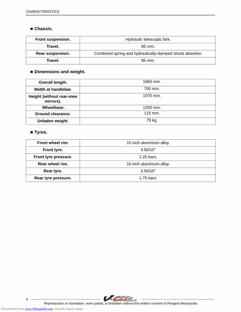
Chassis.
Dimensions and weight.
Tyres.
Front suspension. Hydraulic telescopic fork.
Travel. 85 mm.
Rear suspension. Combined spring and hydraulically-damped shock absorber.
Travel. 85 mm.
Overall length. 1660 mm.
Width at handlebar. 700 mm.
Height (without rear-view mirrors).
1070 mm.
Wheelbase. 1200 mm.
Ground clearance. 115 mm.
Unladen weight. 79 kg.
Front wheel rim. 10 inch aluminium alloy.
Front tyre. 3.50/10"
Front tyre pressure. 1.25 bars.
Rear wheel rim. 10 inch aluminium alloy.
Rear tyre. 3.50/10"
Rear tyre pressure. 1.75 bars.
Downloaded from www.Manualslib.com manuals search engine

CHARACTERISTICS
5Reproduction or translation, even partial, is forbidden without the written consent of Peugeot Motocycles
Brakes
Front disc diameter and thickness 155 mm-4 mm.
Front brake caliper 1 piston of 30.2 mm.
Brake drum diameter. 110 mm.
Chassis markings. Engine marking.
1. VIN (Rear shield). 2. Engine number. - Manufacturer's plate (Right side).
xxxxxxxxxxxxxxxxx
1
XXXXXXXXXXXXXX
2
Downloaded from www.Manualslib.com manuals search engine

SERVICE SCHEDULE AND COMMISSIONING
6Reproduction or translation, even partial, is forbidden without the written consent of Peugeot Motocycles
SERVICE SCHEDULE AND COMMISSIONING
Heavy duty servicing is for vehicles used under "harsh" conditions: door-to-door deliveries, intensive urban use (courier), short journeys with engine cold, dusty areas, ambient temperature over 30°C.
Service operations. 500 kms
or 1 months.
At 2000 kms.
Every 5000 kms
or 12 months
.
Every 10000 kms.
Every 20000 kms.
Heavy duty servicing. 500 kms. At
1000 kms.Every
2500 kms.Every
5000 kms. Every
10000 kms. Check
Throttle cable play. C C C C CSteering column play. C C C C COperation of electrical equipment. C C C C CCondition of the front brake hydraulic control.
C C C C C
Condition of petrol pipes. C C C C CCondition of oil pipes. C C C C CTyre pressures. C C C C CTyre condition, pressure and wear. C C C C CCondition of the front suspension. C C C C CCondition of the rear suspension. C C C C CBrake fluid level. C C C C CBattery electrolyte level*. C C C C CTightness of nuts and bolts. C C C C C
ChangeSpark plug. R R RInlet silencer/air filter. RFront brake pads #. C C CRear brake linings #. C C CDrive pulley bearings and guides #. C C CTransmission belt ##. R R REngine oil (+ clean strainer). R R R R RBrake fluid. Once every 2 yearsRelay box. R R
Check and lubricate Kick starter mechanism. G GDrive pulley/Movable face. G G
Test machine On road. C C C C C
C : CheckN : CleanR : ChangeG : Check and lubricate
* Depending on equipment# Change if necessary## Or once every 5 years
Battery preparation (Except battery without maintenance)*.
Downloaded from www.Manualslib.com manuals search engine
SERVICE SCHEDULE AND COMMISSIONING
7Reproduction or translation, even partial, is forbidden without the written consent of Peugeot Motocycles
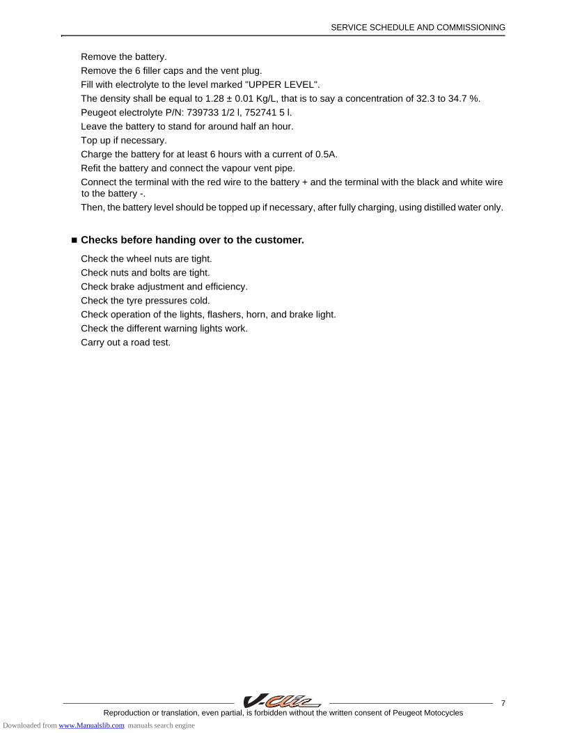
Remove the battery.
Remove the 6 filler caps and the vent plug.
Fill with electrolyte to the level marked "UPPER LEVEL".
The density shall be equal to 1.28 ± 0.01 Kg/L, that is to say a concentration of 32.3 to 34.7 %.
Peugeot electrolyte P/N: 739733 1/2 l, 752741 5 l.
Leave the battery to stand for around half an hour.
Top up if necessary.
Charge the battery for at least 6 hours with a current of 0.5A.
Refit the battery and connect the vapour vent pipe.
Connect the terminal with the red wire to the battery + and the terminal with the black and white wire to the battery -.
Then, the battery level should be topped up if necessary, after fully charging, using distilled water only.
Checks before handing over to the customer.
Check the wheel nuts are tight.
Check nuts and bolts are tight.
Check brake adjustment and efficiency.
Check the tyre pressures cold.
Check operation of the lights, flashers, horn, and brake light.
Check the different warning lights work.
Carry out a road test.
Downloaded from www.Manualslib.com manuals search engine

SPECIAL IMPORTANT POINTS
8Reproduction or translation, even partial, is forbidden without the written consent of Peugeot Motocycles
SPECIAL IMPORTANT POINTS
Oil and fuel.
This engine is designed to run on 95 or 98 unleaded fuel only.
Fuel pipes must absolutely be changed if there are any signs of wear, cracks, etc.
Petrol is highly inflammable, do not smoke in the working area and avoid proximity to flames orsparks. Work in a clear and well-ventilated area. Before carrying out any work, leave the engine to cool for at least 2 hours.
Starting up after overhauling the engine.
When starting the engine hot or cold do not accelerate.
Downloaded from www.Manualslib.com manuals search engine
TIGHTENING TORQUES
9Reproduction or translation, even partial, is forbidden without the written consent of Peugeot Motocycles
TIGHTENING TORQUES
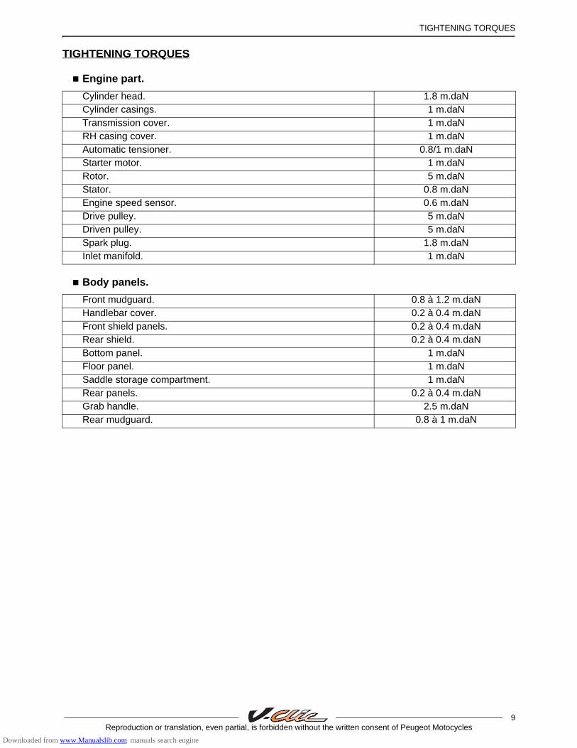
Engine part.
Body panels.
Cylinder head. 1.8 m.daNCylinder casings. 1 m.daNTransmission cover. 1 m.daNRH casing cover. 1 m.daNAutomatic tensioner. 0.8/1 m.daNStarter motor. 1 m.daNRotor. 5 m.daNStator. 0.8 m.daNEngine speed sensor. 0.6 m.daNDrive pulley. 5 m.daNDriven pulley. 5 m.daNSpark plug. 1.8 m.daNInlet manifold. 1 m.daN
Front mudguard. 0.8 à 1.2 m.daNHandlebar cover. 0.2 à 0.4 m.daNFront shield panels. 0.2 à 0.4 m.daNRear shield. 0.2 à 0.4 m.daNBottom panel. 1 m.daNFloor panel. 1 m.daNSaddle storage compartment. 1 m.daNRear panels. 0.2 à 0.4 m.daNGrab handle. 2.5 m.daNRear mudguard. 0.8 à 1 m.daN
Downloaded from www.Manualslib.com manuals search engine
TIGHTENING TORQUES
10Reproduction or translation, even partial, is forbidden without the written consent of Peugeot Motocycles
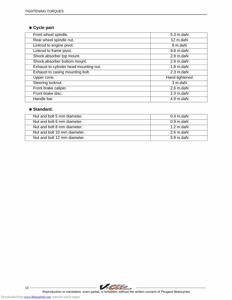
Cycle part
Standard.
Front wheel spindle. 5.3 m.daNRear wheel spindle nut. 12 m.daNLinkrod to engine pivot. 8 m.daNLinkrod to frame pivot. 9.8 m.daNShock absorber top mount. 2.9 m.daNShock absorber bottom mount. 2.9 m.daNExhaust to cylinder head mounting nut. 1.8 m.daNExhaust to casing mounting bolt. 2.3 m.daNUpper cone. Hand tightenedSteering locknut. 3 m.daNFront brake caliper. 2.6 m.daNFront brake disc. 2.3 m.daNHandle bar. 4.9 m.daN
Nut and bolt 5 mm diameter. 0.4 m.daNNut and bolt 6 mm diameter. 0.9 m.daNNut and bolt 8 mm diameter. 1.2 m.daNNut and bolt 10 mm diameter. 2.6 m.daNNut and bolt 12 mm diameter. 3.9 m.daN
Downloaded from www.Manualslib.com manuals search engine

INSTRUMENT PANEL
11Reproduction or translation, even partial, is forbidden without the written consent of Peugeot Motocycles
INSTRUMENT PANEL
Analog functions (hands).
Speedometer.
Double-scale indication, kilometres/miles.
Odometer.
The odometer displays the number of kilometres travelled by the vehicle.
Fuel gauge.
Functions of the instrument panel:
- Speedometer. - Odometer. - Fuel gauge.
Instrument panel indicator lamps:
• Intermitent signal.• High beam.
1. Speedometer.2. Odometer.3. Fuel gauge.4. Intermitent signal.5. High beam.
When a flasher bulb has failed the repeater light and the other flasher light flash more quickly toalert the rider of a failure.
10102020
30304040 5050 6060 7070
8080
E
4545
2525
1010
20203030 4040
5050
0
Km / hKm / hmphmph
F1
35
42
Downloaded from www.Manualslib.com manuals search engine

ELECTRICITY
12Reproduction or translation, even partial, is forbidden without the written consent of Peugeot Motocycles
ELECTRICITY
Fuses and energy distribution.
When the main fuse (10A) is blown, all the the electric functions of the vehicle are disabled.
Replace the burnt out fuse with a new one.
Location of components
1. Battery.2. Ignition sensor.3. Ignition unit.4. Oil level indicator.5. HT coil.
6. Regulator.7. Starter motor relay.8. Horn.9. 10 A fuse.10. Kickstand switch.
8
4
7
1
5
2 39
6
10
Downloaded from www.Manualslib.com manuals search engine

BODY PANELS
13Reproduction or translation, even partial, is forbidden without the written consent of Peugeot Motocycles
BODY PANELS
Location of body components.
1. Central panel. 2. Saddle/Storage compartment. 3. Grab handle.4. Rear cover.5. Mudflap.6. Side panels.7. Lower side fairings.8. Bottom panel.
9. Front mudguard.10. Front shield panels. 11. Front top cover panel. 12. Handlebar front fairing. 13. Handlebar rear fairing. 14. Rear shield. 15. Floor panel. 16. Battery access door.
11
8
12
14
15
76
5
3
2
1
9
10
13
16
4
Downloaded from www.Manualslib.com manuals search engine

BODY PANELS
14Reproduction or translation, even partial, is forbidden without the written consent of Peugeot Motocycles
Body component sequence of disassembly.
*This item may be removed on its own.
2* 3* 4* 11* 9*
13
12*
10
14
8155
6
71
Downloaded from www.Manualslib.com manuals search engine
BODY PANELS
15Reproduction or translation, even partial, is forbidden without the written consent of Peugeot Motocycles
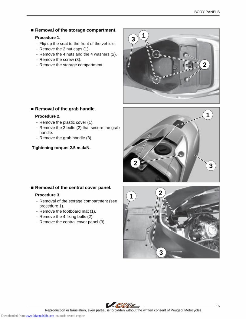
Removal of the storage compartment.
Procedure 1. - Flip up the seat to the front of the vehicle. - Remove the 2 nut caps (1). - Remove the 4 nuts and the 4 washers (2).- Remove the screw (3).- Remove the storage compartment.
Removal of the grab handle.
Procedure 2. - Remove the plastic cover (1).- Remove the 3 bolts (2) that secure the grab
handle.- Remove the grab handle (3).
Tightening torque: 2.5 m.daN.
Removal of the central cover panel.
Procedure 3. - Removal of the storage compartment (see
procedure 1).- Remove the footboard mat (1). - Remove the 4 fixing bolts (2). - Remove the central cover panel (3).
3
2
1
2
1
3
3
1 2
Downloaded from www.Manualslib.com manuals search engine
BODY PANELS
16Reproduction or translation, even partial, is forbidden without the written consent of Peugeot Motocycles
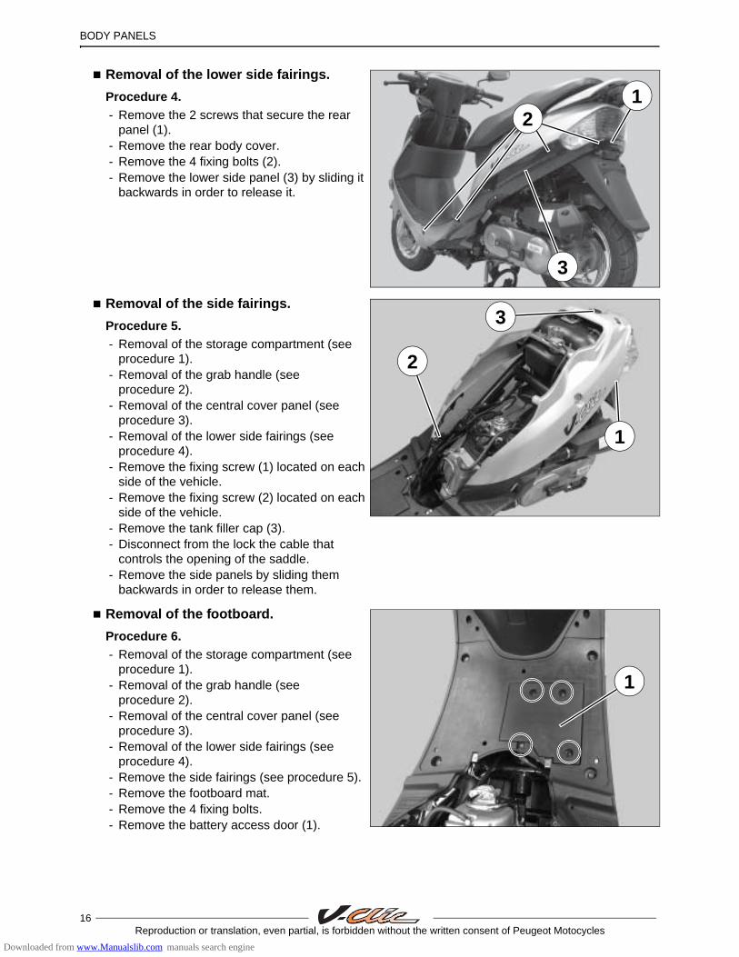
Removal of the lower side fairings.
Procedure 4. - Remove the 2 screws that secure the rear
panel (1).- Remove the rear body cover.- Remove the 4 fixing bolts (2).- Remove the lower side panel (3) by sliding it
backwards in order to release it.
Removal of the side fairings.
Procedure 5.- Removal of the storage compartment (see
procedure 1).- Removal of the grab handle (see
procedure 2).- Removal of the central cover panel (see
procedure 3).- Removal of the lower side fairings (see
procedure 4).- Remove the fixing screw (1) located on each
side of the vehicle.- Remove the fixing screw (2) located on each
side of the vehicle.- Remove the tank filler cap (3).- Disconnect from the lock the cable that
controls the opening of the saddle.- Remove the side panels by sliding them
backwards in order to release them.
Removal of the footboard.
Procedure 6.- Removal of the storage compartment (see
procedure 1). - Removal of the grab handle (see
procedure 2).- Removal of the central cover panel (see
procedure 3).- Removal of the lower side fairings (see
procedure 4).- Remove the side fairings (see procedure 5).- Remove the footboard mat.- Remove the 4 fixing bolts.- Remove the battery access door (1).
12
3
3
1
2
1
Downloaded from www.Manualslib.com manuals search engine

BODY PANELS
17Reproduction or translation, even partial, is forbidden without the written consent of Peugeot Motocycles
- Disconnect the battery.
Remove:
- The battery (2).- The CDI unit (3).
- Remove the 4 fixing bolts (4). - Separate the front of the footboard which is
linked to the rear part of the leg shield panel (5).
- Remove the footboard (6).
Removal of the taillignt.
Removal of the splash guard.
- Removal of the storage compartment (see procedure 1).
- Removal of the grab handle (see procedure 2).
- Removal of the central cover panel (see procedure 3).
- Removal of the lower side fairings (see procedure 4).
- Removal of the side fairings (see procedure 5).
- Disconnect the taillight.- Remove the 2 nuts (1).- Remove the 2 bolts (2).- Remove the taillight.
2
3
5
4
6
2
1
Downloaded from www.Manualslib.com manuals search engine

BODY PANELS
18Reproduction or translation, even partial, is forbidden without the written consent of Peugeot Motocycles
- Remove the splash guard by releasing it from the pins (3) and bracket (4).
Removal of the front top cover panel.
Procedure 7.- Remove the 4 fixing bolts (1).
- Unclip the front cover panel from on top of the front leg shield panel.
- Remove the front top cover panel (2).
3 4
1
2
Downloaded from www.Manualslib.com manuals search engine

BODY PANELS
19Reproduction or translation, even partial, is forbidden without the written consent of Peugeot Motocycles
Removal of the front mudguard.
Procedure 8. - Disconnect the speedometer driver control
cable.- Remove the wheel.- Remove the fixing screw (1) located on each
side of the vehicle.- Remove the front part of the mudguard (2) by
unclipping it from the holder (3).
- Remove the 2 fixing bolts (4).- Remove the rear part of the mudguard and its
holder.
Removal of the front shield panel.
Procedure 9.- Removal of the lower side fairings (see
procedure 4).- Removal of the front top cover panel (see
procedure 7).- Removal of the front mudguard (see
procedure 8).- Remove the 6 fixing bolts.
1
2
4
3
Downloaded from www.Manualslib.com manuals search engine
BODY PANELS
20Reproduction or translation, even partial, is forbidden without the written consent of Peugeot Motocycles
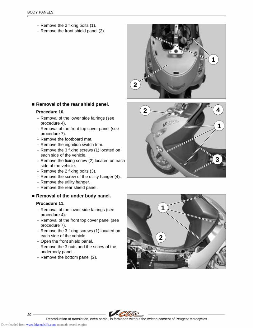
- Remove the 2 fixing bolts (1).- Remove the front shield panel (2).
Removal of the rear shield panel.
Procedure 10.- Removal of the lower side fairings (see
procedure 4).- Removal of the front top cover panel (see
procedure 7).- Remove the footboard mat.- Remove the ingnition switch trim.- Remove the 3 fixing screws (1) located on
each side of the vehicle.- Remove the fixing screw (2) located on each
side of the vehicle.- Remove the 2 fixing bolts (3).- Remove the screw of the utility hanger (4).- Remove the utility hanger.- Remove the rear shield panel.
Removal of the under body panel.
Procedure 11.- Removal of the lower side fairings (see
procedure 4).- Removal of the front top cover panel (see
procedure 7).- Remove the 3 fixing screws (1) located on
each side of the vehicle.- Open the front shield panel.- Remove the 3 nuts and the screw of the
underbody panel.- Remove the bottom panel (2).
1
1
2
11
2 44
3
1
2
Downloaded from www.Manualslib.com manuals search engine

BODY PANELS
21Reproduction or translation, even partial, is forbidden without the written consent of Peugeot Motocycles
Removal of a headlight bulb.
- Remove the fastening screw (1).- Remove the 2 fixing bolts (2).- Remove the handlebar front cover.
- Remove the lamp lens (3).- Disconnect the bulb.- Remove the bulb.
Removal of a taillight bulb.
- Remove the 2 screws that secure the rear panel.
- Remove the rear body cover (1).- Remove the 2 screws that secure the taillight
lens (2).- Disconnect the bulb.- Remove the taillight lens ans turnsignal light
lenses.- Remove the bulb.
2
1
2
3
13
2
1
Downloaded from www.Manualslib.com manuals search engine
BODY PANELS
22Reproduction or translation, even partial, is forbidden without the written consent of Peugeot Motocycles
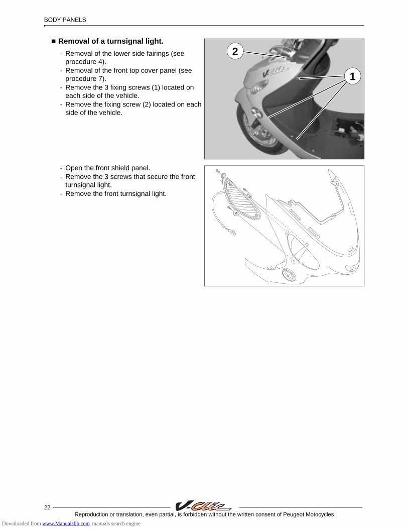
Removal of a turnsignal light.
- Removal of the lower side fairings (see procedure 4).
- Removal of the front top cover panel (see procedure 7).
- Remove the 3 fixing screws (1) located on each side of the vehicle.
- Remove the fixing screw (2) located on each side of the vehicle.
- Open the front shield panel.- Remove the 3 screws that secure the front
turnsignal light.- Remove the front turnsignal light.
1
2
Downloaded from www.Manualslib.com manuals search engine
WORKING ON THE ENGINE WITHOUT REMOVING THE ENGINE
23Reproduction or translation, even partial, is forbidden without the written consent of Peugeot Motocycles
WORKING ON THE ENGINE WITHOUT REMOVING THE ENGINE
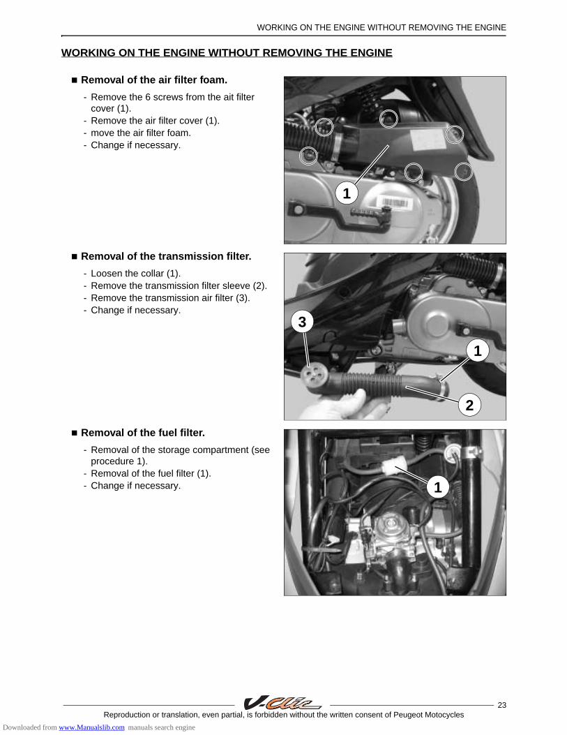
Removal of the air filter foam.
- Remove the 6 screws from the ait filter cover (1).
- Remove the air filter cover (1).- move the air filter foam.- Change if necessary.
Removal of the transmission filter.
- Loosen the collar (1).- Remove the transmission filter sleeve (2).- Remove the transmission air filter (3).- Change if necessary.
Removal of the fuel filter.
- Removal of the storage compartment (see procedure 1).
- Removal of the fuel filter (1).- Change if necessary.
1
3
1
2
1
Downloaded from www.Manualslib.com manuals search engine
24Reproduction or translation, even partial, is forbidden without the written consent of Peugeot Motocycles
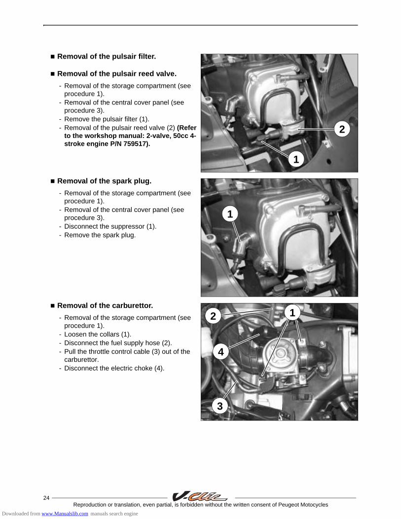
Removal of the pulsair filter.
Removal of the pulsair reed valve.
- Removal of the storage compartment (see procedure 1).
- Removal of the central cover panel (see procedure 3).
- Remove the pulsair filter (1).- Removal of the pulsair reed valve (2) (Refer
to the workshop manual: 2-valve, 50cc 4-stroke engine P/N 759517).
Removal of the spark plug.
- Removal of the storage compartment (see procedure 1).
- Removal of the central cover panel (see procedure 3).
- Disconnect the suppressor (1). - Remove the spark plug.
Removal of the carburettor.
- Removal of the storage compartment (see procedure 1).
- Loosen the collars (1). - Disconnect the fuel supply hose (2).- Pull the throttle control cable (3) out of the
carburettor.- Disconnect the electric choke (4).
2
1
1
2
12
3
4
Downloaded from www.Manualslib.com manuals search engine
25Reproduction or translation, even partial, is forbidden without the written consent of Peugeot Motocycles
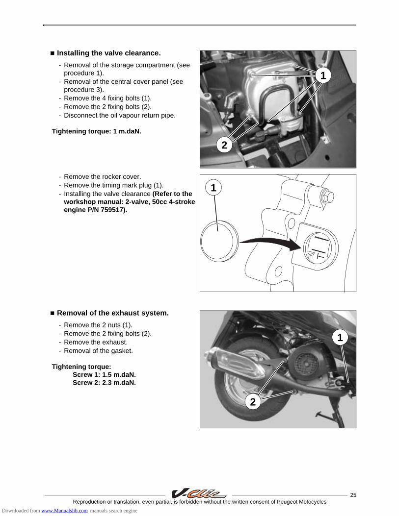
Installing the valve clearance.
- Removal of the storage compartment (see procedure 1).
- Removal of the central cover panel (see procedure 3).
- Remove the 4 fixing bolts (1).- Remove the 2 fixing bolts (2).- Disconnect the oil vapour return pipe.
Tightening torque: 1 m.daN.
- Remove the rocker cover.- Remove the timing mark plug (1).- Installing the valve clearance (Refer to the
workshop manual: 2-valve, 50cc 4-stroke engine P/N 759517).
Removal of the exhaust system.
- Remove the 2 nuts (1).- Remove the 2 fixing bolts (2).- Remove the exhaust.- Removal of the gasket.
Tightening torque: Screw 1: 1.5 m.daN.Screw 2: 2.3 m.daN.
1
2
1
1
2
Downloaded from www.Manualslib.com manuals search engine

26Reproduction or translation, even partial, is forbidden without the written consent of Peugeot Motocycles
Removal of the cylinder head.
Removal of the cylinder / piston.
- Removal of the storage compartment (see procedure 1).- Removal of the central cover panel (see procedure 3).- Removal of the exhaust system.
For the following steps:
- Removal of the intake pipe. - Removal of the cooling volutes.- Removal of the rocker cover.- Removal of the chain tensioner.- Removal of the cylinder head.- Removal of the cylinder.- Removal of the piston.
Refer to the workshop manual: 2-valve, 50cc 4-stroke engine P/N 759517.
Downloaded from www.Manualslib.com manuals search engine
MISCELLANEOUS OPERATIONS
27Reproduction or translation, even partial, is forbidden without the written consent of Peugeot Motocycles
MISCELLANEOUS OPERATIONS
Removal of the engine.
- Removal of the storage compartment (see procedure 1).
- Removal of the central cover panel (see procedure 3).
- Removal of the carburettor (see page 25).- Disconnect the vacuum hose.- Disconnect the oil vapour return pipe.- Remove the 2 screws that secure the air filter.- Remove the air filter.- Disconnect:
- The suppressor.- The magneto.- The starter motor.
- Suspend or immobilize the machine securely.- Remove the shock absorber lower mount .- Remove the nut that secures the engine.- Remove the bolt that secures the engine.- Remove the engine.
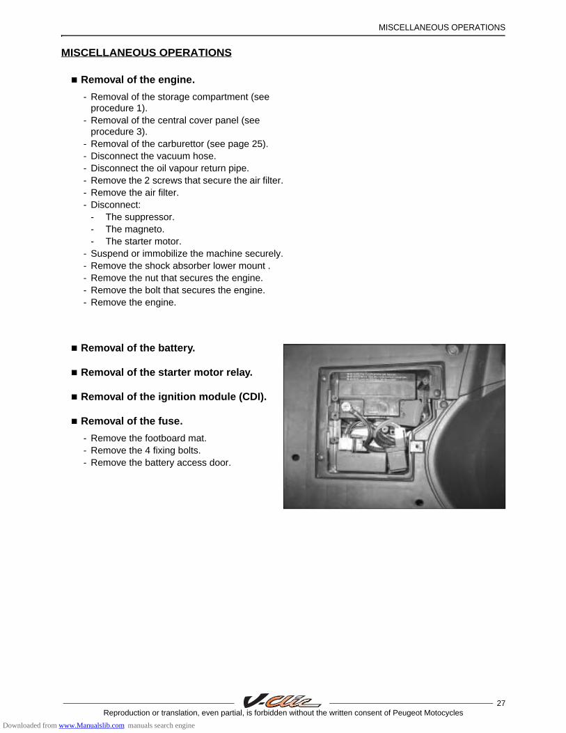
Removal of the battery.
Removal of the starter motor relay.
Removal of the ignition module (CDI).
Removal of the fuse.
- Remove the footboard mat.- Remove the 4 fixing bolts.- Remove the battery access door.
Downloaded from www.Manualslib.com manuals search engine

MISCELLANEOUS OPERATIONS
28Reproduction or translation, even partial, is forbidden without the written consent of Peugeot Motocycles
Removal of the regulator.
Removal of the choke resistor.
Removal of the horn.
Removal of the blinker unit.
Removal of the ignition switch.
- Removal of the front top cover panel (see procedure 7).
Removal of the high tension coil.
- Removal of the storage compartment (see procedure 1).
- Removal of the central cover panel (see procedure 3).
- Remove the lower RH side fairing (see procedure 4).
- Disconnect the high voltage coil (1).- Disconnect the suppressor.- Remove the fastening screw (2).- Remove the high tension coil.
Removal of the kickstand contact switch.
- Remove the lower LH side fairing (see procedure 4).
- Disconnect the kickstand contact switch.- Remove the 2 fixing bolts (1).- Remove the lickstand cinstact switch.
1
2
1
Downloaded from www.Manualslib.com manuals search engine

MISCELLANEOUS OPERATIONS
29Reproduction or translation, even partial, is forbidden without the written consent of Peugeot Motocycles
Removal of the fuel gauge.
Removal of the tank.
- Removal of the storage compartment (see procedure 1).
- Removal of the grab handle (see procedure 2).
- Removal of the central cover panel (see procedure 3).
- Removal of the lower side fairings (see procedure 4).
- Removal of the side fairings (see procedure 5).
- Disconnect the fuel gauge (1).- Remove the 4 fixing bolts (2).- Remove the fuel gauge.- Remove the flat gasket.
- Remove the 2 fixing bolts (2).- Remove the 2 nuts (3).- Remove the holder and saddle lock
assembly (4).- Loosen the 2 nuts (5).- Remove the 2 fixing bolts (6).- Remove the grab handle holder.- Remove the tank.
Removal of the front wheel.
- Unscrew the speedometer cable from the drive system (1).
- Remove the wheel spindle nut.- Remove the wheel.- Remove the spacer.- Remove the speedometer driver (2).
Tightening torque: 5.3 m.daN.
2
1
2
3
4
5 5
6 6
1
2
Downloaded from www.Manualslib.com manuals search engine

MISCELLANEOUS OPERATIONS
30Reproduction or translation, even partial, is forbidden without the written consent of Peugeot Motocycles
Removal of the rear wheel.
- Removal of the exhaust system (see page 25).
- Remove the nut and the washer (1).- Remove the wheel.
Tightening torque: 12 m.daN.
Removal of the calliper.
Removal of the brake pads.
- Loosen the screw (1) that secures the calliper to the yoke.
- Remove the 2 screws that secure the brake calliper, but do not disconnect it (2).
Tightening torque: 2.6 m.daN.
- Remove the screw (1).- Pivot the calliper relative to the yoke.- Remove the calliper yoke.
Note: If the caliper is to be changed, the hydraulic control must be slackened off before removal.
1
1
2
Downloaded from www.Manualslib.com manuals search engine
MISCELLANEOUS OPERATIONS
31Reproduction or translation, even partial, is forbidden without the written consent of Peugeot Motocycles
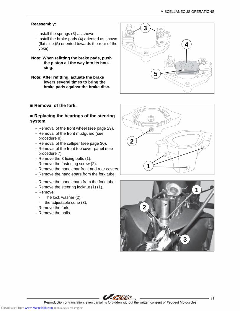
Reassembly:
- Install the springs (3) as shown.- Install the brake pads (4) oriented as shown
(flat side (5) oriented towards the rear of the yoke).
Note: When refitting the brake pads, push the piston all the way into its hou-sing.
Note: After refitting, actuate the brake levers several times to bring the brake pads against the brake disc.
Removal of the fork.
Replacing the bearings of the steering system.
- Removal of the front wheel (see page 29).- Removal of the front mudguard (see
procedure 8).- Removal of the calliper (see page 30).- Removal of the front top cover panel (see
procedure 7).- Remove the 3 fixing bolts (1).- Remove the fastening screw (2).- Remove the handlebar front and rear covers.- Remove the handlebars from the fork tube.
- Remove the handlebars from the fork tube.- Remove the steering locknut (1) (1).- Remove:
- The lock washer (2).- the adjustable cone (3).
- Remove the fork.- Remove the balls.
3
4
5
1
2
3
2
1
Downloaded from www.Manualslib.com manuals search engine

MISCELLANEOUS OPERATIONS
32Reproduction or translation, even partial, is forbidden without the written consent of Peugeot Motocycles
- Using a drift, remove the steering head cups.- Using a drift, remove the steering headset
cone (1).
- Install the following new parts:- The fork cone (1).- The steering headset cups (2).
Steering system tightening method.
- Grease the cup bearing races.- Fit 26 balls (1) for the upper cup and
29 balls (2) for the lower cup (Diameter: 4 mm).
- Fit the fork into the steering column.- Install the adjustable cone and tighten it (3).- Loosen and then retighten the adjustable
cone.- Fit the lock washer (4).- Install the steering head locknut and tighten
it (5).
Tightening torque: 3 m.daN.
1
2
1
1
2
3
4
5
Downloaded from www.Manualslib.com manuals search engine

P/N 759522
In our permanent concern to make improvements PEUGEOT MOTOCYCLES reserves the right to suppress, modify, or add any reference mentioned
DC/PS/APV Printed in the E.U. 03/2007 (non contractual pictures).
Downloaded from www.Manualslib.com manuals search engine