Embed Size (px)
Citation preview

What's New in VCarve Pro 8
A quick start guide for VCarve Pro upgraders
Copyright © Vectric Ltd. Document V.1.0

Copyright © 2015 Vectric Ltd. All Rights Reserved. Page | 2
Contents CONTENTS ................................................................................................................................... 2
OVERVIEW ................................................................................................................................... 3
NEW 3D CLIP ART ......................................................................................................................... 4
NEW DRAWING TOOLS ................................................................................................................. 8
Create Vector Texture ......................................................................................................................... 9
Trim Objects ...................................................................................................................................... 12
ENHANCED & EXTENDED DRAWING TOOLS ................................................................................ 14
NEW MODELLING TOOLS ............................................................................................................ 16
Import a Component or 3D Model ................................................................................................... 17
Component Properties ...................................................................................................................... 20
Component Manager ........................................................................................................................ 23
Smooth Components ........................................................................................................................ 28
Scale Model Height ........................................................................................................................... 29
Slice Model ........................................................................................................................................ 30
THE 3D CLIPART TAB .................................................................................................................. 32
Integrated Windows Explorer Thumbnail Support ........................................................................... 34
NEW TOOLPATH FEATURES ........................................................................................................ 35
Create Merged Toolpath ................................................................................................................... 36
Create Job Sheet ............................................................................................................................... 39
Rough Machining Toolpath (3D) ....................................................................................................... 40
Finish Machining Toolpath (3D) ........................................................................................................ 42
ENHANCED & EXTENDED TOOLPATH FEATURES .......................................................................... 44
MISCELLANEOUS IMPROVEMENTS ............................................................................................. 48
DOCUMENT VARIABLES .............................................................................................................. 49

Copyright © 2015 Vectric Ltd. All Rights Reserved. Page | 3
Overview Welcome to the What’s New document for the latest version of VCarve Pro. Please note that this document is intended for existing VCarve Pro customers who have recently upgraded to the latest version. As such, it only includes details of the incremental changes and enhancements to the previous version of the software. If you are new to VCarve Pro then this document probably isn’t the one for you. Instead please take the time to watch the extensive supporting tutorial videos provided with VCarve Pro to help you get started. Once you are up and running, you will find the Help->Help Contents menu command will open a full electronic reference to every tool and feature in VCarve Pro.
This document is divided into three sections focusing on the main areas of VCarve Pro: Drawing, Modelling and Toolpaths. In each Section there are separate parts highlighting completely new tools, and a summary of enhancements and extensions to existing tools that you should already be familiar with. Finally, the Miscellaneous Improvements section documents the remaining changes that have been made that do not fit into one of these categories.
The new version of VCarve Pro has seen some significant drawing tool improvements along with many productivity enhancing additions to the 2D and 2.5D toolpaths which are detailed later in this document, perhaps the most major change though is support for importing and machining 3D models directly within VCarve Pro.
The 3D functionality makes it possible to import a single 3D mesh based model from another design system (STL, 3DM, SKP, 3DS, ASC, PRJ, DXF, LWO, WRL and OBJ). This can be scaled, positioned and then machined using 3D Roughing and 3D Finishing toolpaths. In addition the 2D and 2.5 toolpaths within VCarve Pro can also be combined with these 3D toolpaths to cut accurate pockets, drill holes etc. and you can even take any of the 2D or 2.5D toolpaths and project them onto the 3D surface of the imported model.
The Modeling part of VCarve Pro provides even more flexibility if working with Vectric Clip Art files in the V3M file format. An unlimited number of these can be imported into the software and then assembled together to make more complex 3D layouts. As with the individual 3rd party models these can be 3D machined with the same flexibility. V3M file format Clip Art is available from Vector Art 3D – http://www.vectorart3d.com and Design and Make: http://www.designandmake.com. In addition the new version comes with a large selection of Clip Art to get you started which is shown on the following pages.

Copyright © 2015 Vectric Ltd. All Rights Reserved. Page | 4
New 3D Clip Art The new version of VCarve Pro now includes a significant number of 3D Clip Art models which can be used with the software for import, assembly and machining. Over 70 of these models are from the Vector Art 3D website - http://www.vectorart3d.com. Each of them comes in the three Vector Art 3D styles; A-Regular, B-Dished and C-Recessed, making 210 models in total. These models alone would cost over US$2000 if purchased from the website. The additional models included and their variants bring the Clip Art total to over 300 files in V3M file format. On the following four pages you can see an image of the regular version of each model that comes with the new version.
The first 25 3D designs included in the VCarve Clip Art

Copyright © 2015 Vectric Ltd. All Rights Reserved. Page | 5
The next 35 3D designs included in the VCarve Clip Art

Copyright © 2015 Vectric Ltd. All Rights Reserved. Page | 6
The next 35 3D designs included in the VCarve Clip Art

Copyright © 2015 Vectric Ltd. All Rights Reserved. Page | 7
The final 26 3D designs included in the VCarve Clip Art

Copyright © 2015 Vectric Ltd. All Rights Reserved. Page | 8
New Drawing Tools This latest version of VCarve Pro introduces several entirely new drawing tools and features, which are fully documented in this section. These include:
• Create Vector Texture tool. • Trim Objects to a Vector Boundary.
Create Vector Texture Tool. Repeating vector patterns can be created using the Create Vector Texture tool. These vectors can be machined using the Profile and Texture toolpaths to create decorative wavy texture panels along with wood-grain and sand-blast effects.
To use the tool click the icon on the drawing tab. To control the area the vector texture is created within you can select a closed vector as a boundary to limit the area the new vectors are created within.
Trim Objects Tool. The trim tool allows you to trim all the vector objects inside a given boundary. It is much more efficient than manually trimming all the contours with the trimming scissors, and allows the trimming of closed and open contours.
This is a real time saving tool giving the user a quick and easy method to rapidly trim many vectors to a boundary shape.

Copyright © 2015 Vectric Ltd. All Rights Reserved. Page | 9
Create Vector Texture Repeating texture patterns can be created using the Create Vector Texture tool. These vectors can be machined in a variety of ways to create attractive textures.
To use the tool click the icon on the drawing tab. If required, select any contours that you wish the pattern to be created within. By using the sliders and edit boxes on the form the style of the created
pattern can be varied. Use the Preview button to preview your
created texture and when you are happy click the OK button to
create the pattern.
Angle The lines in the texture are created at an angle. This value can be set to any value between -90 degrees and 90 degree.
Angle of 30 degrees
Line Spacing The line spacing controls the distance between the contours created by the tool. Use the edit box labeled Max. Spacing to enter a maximum value of line spacing. The slider underneath the edit box controls the degree of variation in the line spacing. If the slider is to the far left then this mean variation is at a minimum and so the lines are evenly spaced. If the slider is to the far right the variation is highest and so the distance between created contours varies between zero and the maximum spacing specified.
Minimum variation Maximum Variation

Copyright © 2015 Vectric Ltd. All Rights Reserved. Page | 10
Wave Parameters Within this section of the form the created pattern can be made to behave in a wave-like fashion. This wave is controlled by two parameters: the amplitude and wavelength.
Wavelength The wavelength describes the length over which the contours shape repeats itself. A bigger wavelength gives a long wave whilst a small wavelength gives a short wave.
Short wavelength Long wavelength
Amplitude The amplitude describes the height of the wave. Larger amplitude means a taller wave and smaller amplitude means a shallow wave.
Small amplitude Large Amplitude
Noise The noise slider controls the degree of randomness applied to the above values and can be used to create less regular patterns.
No noise Medium noise High noise

Copyright © 2015 Vectric Ltd. All Rights Reserved. Page | 11
Vector Layer To create the vectors on a new layer make sure the check box labeled Place Vectors on Layer is checked and enter the layer name into the edit box labeled Name
Applications The vectors created by this function have many applications but a key one is to combine them with either a Profile Toolpath or where available the Texture Toolpath to create decorative panels and background textures, a small selection of the possible results you can derive from this combination are shown in the images below.
Ball Nose Tool - Wave Pattern V-Bit Tool – Swirl Pattern Ball Nose Tool – Grain Pattern

Copyright © 2015 Vectric Ltd. All Rights Reserved. Page | 12
Trim Objects The trim tool allows you to trim all the objects inside a given boundary. It is much more efficient than manually trimming all
the contours with the trimming scissors, and allows the trimming of closed contours, open contours and components.
To use the trim tool first select the tool by clicking the icon on the drawing tab. You then must select the objects you wish to be trimmed first and then then the object you wish to trim against last. Finally, choose whether you want to clear the area inside the boundary or outside of the boundary.
If the Clear outside boundary option is selected then all the objects that intersect this boundary are clipped, and the area outside is removed. If the Clear inside boundary option is selected, then the parts of the selected objects which lie inside the boundary are removed.
Geometry before
trimming. Select the lines first and then
the circle
Trimmed vectors using Clear inside
boundary
Trimmed vectors using clear outside boundary
If you want to use multiple vectors for the trimming boundary then these should be used for trimming. To group a collection of vectors select the vectors, right click and choose Group Objects from the drop down menu, or alternately select press the G key.

Copyright © 2015 Vectric Ltd. All Rights Reserved. Page | 13
Group the vectors you want to use
as the clipping boundary Select the vectors you wish to clip
followed by the grouped boundary, finally trim use the trimming tool .

Copyright © 2015 Vectric Ltd. All Rights Reserved. Page | 14
Enhanced & Extended Drawing Tools This section details the improvements that have been made to features you will already be familiar with from earlier versions of VCarve Pro and includes the following:
• Mirror Node Editing • Guidelines
Mirror Node Editing It can be very useful to edit vector shapes so both sides of an object are updated symmetrically. When using the Node editing mode the new Mirror Node Editing option allow you to adjust the nodes dynamically with either horizontal or vertical symmetry.
To activate this you can toggle Mirror Node Editing Mode on and off either Horizontally or Vertically by pressing the H or V key, respectively, while in node editing mode. Within this mode, you can select multiple nodes, on either side of the indicated dotted centerline, and the move the selected nodes. The nodes on the opposite sides will automatically move to maintain the mirror image. The centerline around which the mirroring will occur is created automatically from the bounding box of the object being edited. It is indicated in the 2D View by the dotted line when H or V is pressed.
Guidelines
Angled Guidelines As well as perfectly vertical and horizontal guidelines, you can now also create guidelines at custom angles. Guides can be given an angle by either entering an angle into the New Angle box or
dragging the slider and clicking Apply .
Angles are measured in degrees counterclockwise from the x-axis. From an angled guide you can only create relative parallel guides. Guide lines can be locked in position to stop them from being inadvertently moved by ticking the Lock Guide option. Additional Guide Lines can be added that are positioned using absolute or incremental coordinates. Enter the Absolute or relative
positions and Click Create New Guides(s) .

Copyright © 2015 Vectric Ltd. All Rights Reserved. Page | 15
Snapping to Geometry Guidelines can now be snapped to the salient features of your existing geometry: center points, line spans, nodes etc. Simply drag the guideline over the area of interest by click and dragging using the left mouse button. As the mouse pointer moves over snap points it will change to indicated the type of snap point that is currently activated. If you release the mouse button while the pointer is indicating a snap point then the guideline will be positioned precisely according to the snap point.

Copyright © 2015 Vectric Ltd. All Rights Reserved. Page | 16
Create
Compone
Smooth Components
Scale Mod
Slice
Import a Component or 3D Model
New Modelling Tools The new version of VCarve Pro sees the introduction of the ability to import and manipulate 3D models directly within the program.
The software allows a single 3rd party file to be imported (something designed in another 3D modeling program, example: STL, OBJ etc.) or you can import multiple Vectric Clip Art files (V3M file format) for assembly to make a more complex arrangement.
To manage this, The Modeling Tab has been added to the program that by default is positioned on the left of the interface with the Drawing Tab and Layers Tab. In addition the software now also has The 3D Clipart Tab also located with the other design tabs to let you browse the models and vectors that comes with the software and other files you may add to your clip art library.
The Modeling Tab The Modeling Tools section of the Modeling tab contains all the icons buttons which relate to commands for importing, editing and manipulating 3D Components.
Below the Modeling Tools section you will find the Component Manager which lists any 3D components you have imported and allows you to control how they interact with each other to create the Composite Model which is the combined 3D shape you see in the 3D View.
Import a Component or 3D Model
Component Properties
Create Vector Boundary From Selected Components
Smooth Components
Scale Model Height
Slice Model

Copyright © 2015 Vectric Ltd. All Rights Reserved. Page | 17
Import a Component or 3D Model This command opens the File Open dialog window, allowing V3M and importable 3rd party 3D files to be selected and opened. If
you select a 3rd party 3D model format, the Orientate Model form will open (see below) to allow you to manipulate the 3D model before it is converted into a Component.
Important Note: VCarve Pro will only allow a single 3rd party 3D file to be imported into a session of the software but will allow multiple V3M files to be loaded and assembled together.
V3M
V3M is a proprietary file format developed by Vectric for Vector Art 3D and Design and Make. Files in this format can be purchased from www.vectorart3d.com and www.designandmake.com when imported into VCarve Pro these will create a new Component with the same name as the file. This will be imported at the size and position the part was saved in the original file.
STL
DXF
3DS
OBJ
SKP
3DM
etc.
VCarve Pro will import mesh based 3D models in many different file types. These models can be completely 3 dimensional (ie. have a front, back etc.), this means that when one of these type of files is opened that it must first be sized and oriented using the Orientate 3D Model form before a 3D Component can be created in the software (VCarve Pro only represents bas-relief so cannot work with a completely 3D object). Once the file becomes a Component it will have the same name as the original imported file.
Note: If you wish to read data from a 3D digitizer or scanning device then STL is typically the best format that should be used to import the data into VCarve Pro. Many software packages that work with a scanner offer an STL export option, if not then a third party software program may be required to convert the data to an STL model.

Copyright © 2015 Vectric Ltd. All Rights Reserved. Page | 18
Importing a 3D Model – (STL, DXF, 3DS, OBJ etc.) When one of these formats are chosen for 3D file Import, the imported model needs to be oriented and scaled before it can become a 3D Component. A special import window is opened and a set of orientation/scaling tools enabled which are controlled using the form shown below. There is also a video tutorial that shows this process.
Initial Orientation Choose one of the 6 options to determine the most suitable direction on the model that defines the top surface (upper Z) that you want to use when it’s converted into a Component.
You can also use the five options for Rotation about Z Axis to modify the position of the part being imported at this stage.
Interactive Rotation The default choice XYZ-View allows you to left-click in the 3D View with the mouse to rotate your view so you can examine the part from different angles. Using this will not change the orientation of the part for import. If you select one of the other four options above the word Model then this will adjust the actual positional orientation of the imported part. Choosing the XYZ option will allow rotation around all three axes simultaneously, X, Y or Z will only allow rotation around the specified axis. This is also done using the left-click in the 3D View with the mouse.
Model Size
Lock XYZ ratio Un-checking this option allows the model to be distorted from its original shape, this means independent X, Y and Z sizes can be entered, leaving it checked fixes the ratio so it cannot be distorted and will automatically scale the other axis as you enter new values for X, Y or Z. X Enter the size you would like for the X axis dimension of the model. Y Enter the size you would like for the Y axis dimension of the model. Z Enter the size you would like for the Z axis dimension of the model.
Apply Applies the values you have entered for the X, Y or Z dimensions and scales the others if you have the Lock XYZ ratio option selected.
Many mesh files do not inherently have the units that they were made in embedded in the files, so the software is not able to tell if the files are supposed to be inches or metric, they will just have a unit value. Therefore it is quite common to need to scale the part from inch to metric or vice versa.

Copyright © 2015 Vectric Ltd. All Rights Reserved. Page | 19
Units Choose the unit of measurement (mm or inches) that you are working in, within the part the file is being imported into.
Scale mm/inches Scales the X, Y and Z values up or down depending which Unit option is selected. If mm is selected then the software assumes you want to scale the values up so multiplies the current values by 25.4, if inches is selected it assumes you want to scale the values down and divided them by 25.4.
Zero Plane Position In Model This slider bar determines where the 3D model will be cut-off when converting to a Component. You can move this up and down with the mouse or use the Middle or Bottom buttons to locate the plane in the correct position.
Note: Anything in the original model which is an undercut (goes underneath another part of the 3D model) will be discarded and a vertical wall will be created down to the plane from the silhouette (looking down Z axis) edge of the model.
Discard data below zero plane Checking this will remove any data below the original Zero level within the imported 3D model. If the model is effectively a negative model such as a dished or recessed design with a flat plane then you should uncheck this option to make sure you retain the 3D data below the plane.
Create both sides If this option is checked, two components will be created - one looking down the Z axis from above to the zero plane and one looking up from below. After the components have been created, both will be visible and in the same position in the model. You will need to move the components apart or switch off the visibility of one of the components before you make additional edits or generate toolpaths. This will provide you with the geometry that can be edited to cut the original imported 3D part as a 2-sided job if required.
Center Model The Center Model button which will move the center of the model’s bounding box to datum
position (XYZ zero). This may change the Zero Plane position in the model.
OK Creates a 3D Component based on the settings in the form, the Component will have the same name as the imported file. If you selected ‘Create both sides’ you will have two components with the name of the imported file followed by the suffixes -Top and Bottom.
Cancel Cancels the Import function and returns to the standard Modeling Tab icons.
Copyright © 2015 Vectric Ltd. All Rights Reserved. Page | 20
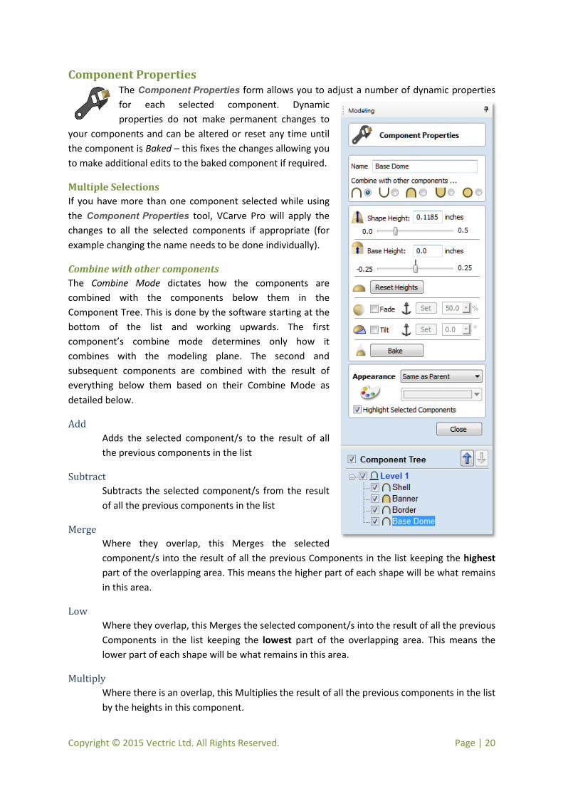
Component Properties The Component Properties form allows you to adjust a number of dynamic properties for each selected component. Dynamic properties do not make permanent changes to
your components and can be altered or reset any time until the component is Baked – this fixes the changes allowing you to make additional edits to the baked component if required.
Multiple Selections If you have more than one component selected while using the Component Properties tool, VCarve Pro will apply the changes to all the selected components if appropriate (for example changing the name needs to be done individually).
Combine with other components The Combine Mode dictates how the components are combined with the components below them in the Component Tree. This is done by the software starting at the bottom of the list and working upwards. The first component’s combine mode determines only how it combines with the modeling plane. The second and subsequent components are combined with the result of everything below them based on their Combine Mode as detailed below.
Add Adds the selected component/s to the result of all the previous components in the list
Subtract Subtracts the selected component/s from the result of all the previous components in the list
Merge Where they overlap, this Merges the selected component/s into the result of all the previous Components in the list keeping the highest part of the overlapping area. This means the higher part of each shape will be what remains in this area.
Low Where they overlap, this Merges the selected component/s into the result of all the previous Components in the list keeping the lowest part of the overlapping area. This means the lower part of each shape will be what remains in this area.
Multiply Where there is an overlap, this Multiplies the result of all the previous components in the list by the heights in this component.

Copyright © 2015 Vectric Ltd. All Rights Reserved. Page | 21
Shape Height: Use the slider or type in a specific percentage to scale the height of the selected Component(s) up or down based on its current height (100%).
Enter a value in the Shape Height edit box directly, or use the slider to adjust the height of your component selection interactively. In either case, the 3D view of the component will update automatically as you adjust the value. If you hit the space bar it will immediately apply the value without having to wait a few seconds for the software to update it.
Base Height: Enter a specific value into this box to raise the Component up vertically by a thickness you specify. This can be useful to help move a Component up so it sits proud of another shape it is Merging with. The values entered in here can also be applied by hitting the space bar or waiting a few seconds.
Reset Heights The Reset Heights button will remove the dynamically applied Shape and Base height settings from
the selected component. To reset just the Base Height back to zero easily using the slider control, double click the central line marker above the slider bar.
Fade When this option is checked the user can fade the Z depth of the Component. The first part of this
operation (once the option is checked) is to select the Set Anchor button – then click two points in
the 2D view. The first click specifies the point which will remain at the current height. The second click specifies the point that the Component will be faded down toward. The shape will fade down from the first point to the second by the percentage selected. Change the strength of the fade by clicking the down arrow next to the percentage value and using the slider to move this up and down or type in a specific value for the amount you would like to reduce the depth. The fade will be applied linearly between the two selected points. This is a useful tool for giving the effect of a Component fading into the distance to help with overlapping areas of Components if you want to lower an area to give it the appearance of going behind another one.
Tilt When this option is checked the user can set a direction and angle to tilt the Component up in the Z
axis. The first part of this operation (once the option is checked) is to select the Set Anchor button –
then click two points in the 2D view. The first click specifies the point which will not move (the pivot point of the tilt). The second click specifies the point that will be tilted upwards by the specified angle (the point that will be raised up). Change the tilt angle by clicking the down arrow next to the value and using the slider to move this up and down or type in a specific value for the angle. This is an extremely useful function for raising a part of one Component above another one when they overlap, without having to raise the whole Component up using the Base Z Position option, in some cases this allows the overlapping areas to sit proud without having to create a deep raised wall around the whole edge of the Component.

Copyright © 2015 Vectric Ltd. All Rights Reserved. Page | 22
The Bake button Sometimes it’s useful to apply a component’s dynamic properties permanently, one example where this is useful is so that further dynamic changes can be applied ‘on top’ of previous ones. To do this,
use the Bake button.
Appearance VCarve Pro gives you a lot of control over the appearance of the 3D shaded image. For visualization purposes such as customer approval proofs or marketing material each component can be given an individual color or material, an example of this is shown in the image below:
There are four choices available for appearance. If you click on the down arrow to the right of the Appearance options, this choice and the Components position in the list will determine the shaded image of the 3D part. Details of these options and how to use them are covered in detail in the Reference Manual.
Close The Close button will exit the Component Properties form and return to the standard set of
modeling icons.

Copyright © 2015 Vectric Ltd. All Rights Reserved. Page | 23
Component Manager
Understanding the component tree and the composite model The model that you see in the 3D View is the result of progressively combining all of the visible components from the bottom of the Component Tree, to the top. The resulting model is known as the Composite Model. The order in which components are combined can have a significant impact on the final shape of the composite model and so you will often need to move components relative to one another within the Component Tree in order to achieve the end result you are intending.
Note: It is only possible to have multiple components in the Component Tree VCarve Pro when importing Vectric Clip Art files using the V3M file format.
To help you understand how the components are being combined, each component in the tree has an icon indicating how it is currently being combined with the components below.
Add Subtract Merge Low Group
Grouped components are also indicated by their own icon and the presence of a plus or minus control to the left of the visibility checkbox. These controls allow you expand or collapse the group to show or hide the group contents.
Every component exists on a single Level. These levels can be used to organize your modelling process. During the compositing process the contents of a level are combined first before the levels themselves are combined together.
Show/Hide Level’s Contents
Currently Selected Level
Currently Selected Component
Show/Hide Group’s Contents
Nonvisible Components Combine Mode Icon
Visibility Checkbox
Component Visibility The checkbox next to each component in the component tree indicates its visibility. Components which are hidden (their visibility checkbox is un-ticked) do not contribute to the composite model.
When a component is hidden in the component tree, its associated 2D preview is also automatically hidden. However, please note that the reverse is not necessarily true. It is often possible to hide a component’s 2D preview without affecting the component itself – see The relationship between components and their 2D previews , for more information.

Copyright © 2015 Vectric Ltd. All Rights Reserved. Page | 24
Level Visibility The checkbox next to each level in the component tree indicates its visibility. If a level is hidden then all of the components on the level are also hidden and so do not contribute to the composite model.
Changing a Component’s Position within the Composite Model To alter a component’s position in the Composite Model, click and drag a component up or down in the tree. An insert marker will indicate where you are preparing to move the component to. Release the mouse when the marker is in the position you wish to move the component to.
The relationship between components and their 2D previews Components are represented in the 2D View using grayscale component previews. The component’s 2D preview allows it to be manipulated using many of the same tools that are available for vectors.
2D component previews are a great way of interacting with the components you have created, however it is important to understand that the component’s position in the component tree (and therefore the nature of contribution to the composite model) is not related to the drawing order of its 2D Preview image in the 2D View. More information on this is contained in the Ref. Manual.
Selecting a component Once created, 3D Components can be manipulated using any of the three main areas of VCarve Pro’s interface.
Components can be selected in 3 ways:
• By left-clicking on the component’s name in the Component Tree • By left-clicking on the associated grayscale component preview image in the 2D view • By double left-clicking directly on the component in the 3D view
In all cases, the new selection will subsequently be reflected in all three locations. So, for example, selecting a component in the Component Tree will simultaneously cause the associated 2D component preview to become selected in the 2D View, and the same component to become highlighted in red (or green if the selected component is obscured by another component) in the 3D View.

Copyright © 2015 Vectric Ltd. All Rights Reserved. Page | 25
Component Selection in the Component Tree The component tree works in a similar way to the Window’s file explorer. To select a component, simply click on it. To select multiple components, hold down the ctrl key while clicking on each component you wish to add to the selection.
Component Selection in the 2D View The 2D component previews behave exactly the same way as vectors or bitmaps. They can be selected by a single, left-click. Several component previews can also be selected by holding the Shift key down while clicking. Clicking on selected component again activates their interactive transform handles.
Component Selection in the 3D View Because the left mouse button is used for twiddling the 3D view itself, a single left-click cannot be used for component selection directly. However, VCarve Pro’s 3D view supports most of the standard selection concepts described above, using double-clicks instead. Therefore, to select a component in the 3D view it must be double-clicked with the left mouse button. To select multiple components in the 3D view, hold down the shift key and double-click each one you want to select.
Because components may overlap or merge through one another when forming the composite model, you may find that some components become difficult to select directly from the 3D view. In this case you can right click on a point above overlapping components then select from a list of all the objects that lie under that positon.
Right clicking on a point gives a list of all components under this point, choose from the list to select.
You can also double right-click the selected component in the 3D view. The options offered include showing/hiding components, or setting their combine mode within the composite model.
In the 3D view selected object will often be tinted red. On some occasions parts of some components will be obscured by other components. The parts of the objects that are obscured will be tinted green so they are still visible from within the 3D view.
The parts of the selected component which are obscured are tinted a different color.
Copyright © 2015 Vectric Ltd. All Rights Reserved. Page | 26
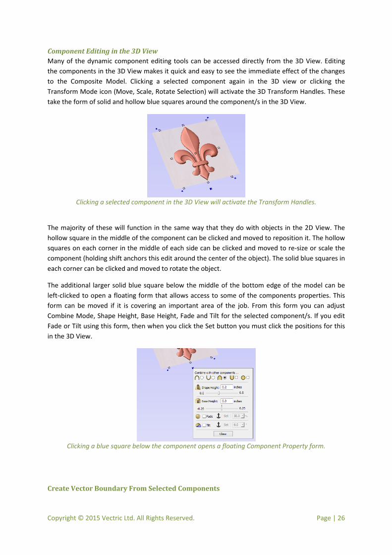
Component Editing in the 3D View Many of the dynamic component editing tools can be accessed directly from the 3D View. Editing the components in the 3D View makes it quick and easy to see the immediate effect of the changes to the Composite Model. Clicking a selected component again in the 3D view or clicking the Transform Mode icon (Move, Scale, Rotate Selection) will activate the 3D Transform Handles. These take the form of solid and hollow blue squares around the component/s in the 3D View.
Clicking a selected component in the 3D View will activate the Transform Handles.
The majority of these will function in the same way that they do with objects in the 2D View. The hollow square in the middle of the component can be clicked and moved to reposition it. The hollow squares on each corner in the middle of each side can be clicked and moved to re-size or scale the component (holding shift anchors this edit around the center of the object). The solid blue squares in each corner can be clicked and moved to rotate the object.
The additional larger solid blue square below the middle of the bottom edge of the model can be left-clicked to open a floating form that allows access to some of the components properties. This form can be moved if it is covering an important area of the job. From this form you can adjust Combine Mode, Shape Height, Base Height, Fade and Tilt for the selected component/s. If you edit Fade or Tilt using this form, then when you click the Set button you must click the positions for this in the 3D View.
Clicking a blue square below the component opens a floating Component Property form.
Create Vector Boundary From Selected Components

Copyright © 2015 Vectric Ltd. All Rights Reserved. Page | 27
This icon can be used to create a vector around the outermost boundary (silhouette) of one or more selected components. The most important use is to generate a vector that can be selected as a toolpath boundary, particularly for 3D Roughing, 3D Finishing and also
Profile (cutout) toolpaths.
To use this function select one or more components and click the Create vector boundary from selected components icon. VCarve Pro will create one or more closed vector boundaries around the edge of the selected components. If more than one closed vector is required to create the boundary, these will be created as a group to make it easier to select them. They would need to be ungrouped before they could be edited individually.

Copyright © 2015 Vectric Ltd. All Rights Reserved. Page | 28
Smooth Components Often it is advantageous to apply a general smoothing effect over the whole of a component (rather than smooth a particular area with the Sculpting Tools). To
use this tool, select the components you wish to smooth and then click the Apply smoothing filter to selected components icon on the Modeling tab. The form will appear and VCarve Pro will take a few seconds to prepare the model for the smoothing operation. You will see a progress bar at the bottom of the screen while it is doing this.
One or more Components can be selected for Smoothing. If you select multiple shapes or a Component Group then the software will need to Bake your selection into a single Component, if applicable you should ensure you have a safe copy of your current Components before proceeding.
Smoothing This slider will allow the user to control the strength of the smoothing applied to the Component. By default 50% smoothing is applied, using the slider different levels of smoothing can be applied to the model. Find the strength which gives you the amount of smoothing you require. If the Max. setting has not smoothed the model enough then hit the Bake Current Smoothing button which resets the smoothing to do further smoothing.
Preserve Transparency Checking this option will keep the smoothing only on the current 3D areas of the selected shapes and not smooth the edges into the background. Un-checking this option will smooth all the edges of the modeled area into the background.
Bake Current Smoothing The bake current smoothing button bakes the current smoothing and resets the form. This means you are able to perform multiple smoothing operations without leaving the form.
Note: Smoothing should be performed with the 3D View visible, so that the effects of the slider can be seen in real time.

Copyright © 2015 Vectric Ltd. All Rights Reserved. Page | 29
Scale Model Height You can scale the individual heights of your 3D Components using the Component Properties form. However, it is also very useful towards the
end of you modeling process to be able to apply a global scaling to your final composite model. This allows you to accurately fit a design within the available material or to manage the depth of cuts required, without having to individually adjust each of the contributing Components.
Scale Height This slider will allow the user to increase and decrease the height of the model as a percentage based on its original height (when the Scale tool was selected).
Set Exact height…
Clicking Set Exact Height… button lets the user define a
specific value (in the current working units) for the height of the model, rather than use the proportional slider.
Apply/OK Exits the dialog keeping the changes made to the Model
Close/Cancel Exits the dialog discarding the changes made to the Model

Copyright © 2015 Vectric Ltd. All Rights Reserved. Page | 30
Slice Model The slicing feature allows the user to divide the Composite Model into Z-Slices each of which will become a Component. This is for customers who need to cut a
part which exceeds the Z depth of their machine gantry, the cutting length of their tools or the thickness of the material they are using. Once the slices have been cut on the CNC then they can be re-assembled to make the finished full depth part.
When this function is executed each slice will become a Component in the Component Manager and can then be moved into position and have toolpaths calculated on it. An example of this is shown in the images below, on the left it shows a scallop shell component that is 3 inches thick, the image below right shows this divided into two separate components, each a 1.5 inch slice of the original.
Note: Before using the Slice model command it is important to make sure that you hide any components that you do not wish to include in the operation.
When the icon is clicked the Slice Model form will appear. This can be used to control the number and thickness of slices which will be created. At the top of the form it will display some reference information showing the thickness of the current Composite Model and also the currently defined Material Thickness (for machining).
Model Slicing
Slice Thickness Checking this option will let you define a particular value for each slice. Right below this the Number of Slices will be displayed which is determined by the Composite Model thickness divided by the Slice Thickness. The model will be sliced from the bottom up and if the Composite Model thickness does not divide exactly by the Slice Thickness then the top slice may not be a whole number. To help indicate how the part is going to be divided the Top Slice Thickness is displayed in the form.

Copyright © 2015 Vectric Ltd. All Rights Reserved. Page | 31
Example: If the Composite Model is 4.75” thick and you define a Slice Thickness of 2” then the software will create 3 Component slices – the bottom and middle slice will both be 2” thick and the top slice will be 0.75” thick.
Number of Slices Checking this option will divide the model into a specific number of slices. The slice thickness will be determined by the Composite Model thickness divided by the Number of Slices defined. This may be a good option to use if the specific slice thickness is not important (for instance if it does not relate to material thickness).
Example: If the Composite Model is 3.96” thick and you define 3 Slices then the software will create 3 Component slices each 1.32” thick.
Create Boundary Vectors Checking this option will cause the slicer to create vector boundaries for each slice. These can be useful for defining the subsequent machining regions required to cut each part. The boundary vectors will be placed on the same layer in the 2D View as the component preview for their associated model slice.
Slice Model Clicking Slice Model will apply the choices made in the form and create the Components which
represent each slice of the Composite Model.
Note: The Component Tree will retain a copy of the original Components in the part as well as the new Slice Components. This may result in a very thick looking model as all the slices will be added to the original shapes. At this point you can delete, undraw or move Components before proceeding with any additional operations.
Close Clicking Close will close the Slice Model form without completing the operation.

Copyright © 2015 Vectric Ltd. All Rights Reserved. Page | 32
The 3D Clipart Tab Integrated Component Clipart The Clipart tab provides quick and convenient access to V3M files or 2D vector artwork.
This tab includes the library browser that allows you to add folders containing V3M Files into the software or you can use the local files option that allows you to quickly see the contents of several folders of V3M files in one place.
By default the Clipart tab can be found on the left-hand side of the VCarve Pro main window, alongside the Drawing, Modeling and Layers tabs.
The 3D clipart tab itself contains two tabbed pages: Local Files and Library Browser. You can swap between these pages by clicking on the page names at the top of the tab.
Note: It is possible to customize VCarve Pros interface by undocking and repositioning its tabs. If your Clipart tab is not visible next to the Drawing and Modeling tabs, please refer to the Overview of the Interface chapter of the Reference Manual for details on working with VCarve Pros tabs.
Local Files The local files browser allows you to select a folder using the file explorer tree in the top section of the page. When you select a folder containing Vectric files (*.crv or *.v3m) the bottom section of the page will fill with thumbnail images of the V3M or CRV files within each folder.
Note: For CRV files that contain components, these components will not be imported into the new session - only the vectors will be imported.
To import a file as a piece of clipart you can simply double click its thumbnail to position the clipart in the center of the job or you could ‘drag & drop’ its thumbnail from the clipart browser, into the 2D or 3D View. To do this:
• Move your mouse over thumbnail image in the clipart browser. • Press and hold down the left mouse button. • While holding down the left mouse button, move the mouse into the 2D or 3D View. A copy
of the thumbnail image will be ‘dragged’ with the mouse pointer. • Release the mouse button to ‘drop’ the clipart file into the 2D or 3D View.
The selected component clipart model or vector outline will be imported at the location of the dropped thumbnail and, if appropriate, added to your model’s Component Tree. Depending on the relative size of your current VCarve Pro model and the piece of clipart you have imported, it may need to be resized to fit using the standard tools on the Drawing tab or directly using the transform handles within the 2D or 3D View.

Copyright © 2015 Vectric Ltd. All Rights Reserved. Page | 33
Library Browser The library browser provides quicker access to folders on your computer which are in frequent use, or perhaps hold the data for the current project you are working on.
To add a folder into your library click on the Add
Folder button which opens up a dialog asking you to
choose the folder you would like to add. Navigate through the tree to choose then folder and click OK. Unlike the Local Files browser the Library browser will only show the clipart that within this folder and folders within this folder. You will not be able to see the whole of the file tree beneath this folder.
Once you have populated your library with folders then clicking on a folder will populate the clipart browser with clipart which are contained in this folder. Any nested folders will also be expanded.
Consider the following example: My current project is a western saloon themed sign. I have split up all the resources I am using for this creation into three folders, so that I have the following folder structure:
Once I have added the Western Saloon folder to my Libraries it appears in the list of folder. When a folder is selected all its immediate subfolders are also shown, but only immediate subfolders, notice that the Toolpath Outlines folder does not appear.
If a folder is selected and it contains clipart files then these are shown in the clipart window
To remove a folder, select from the list of folders and click on the Remove Folder button. This will not delete clipart from your computer; it will just remove the library folder. Folders may be added to the library from the local file browser by right clicking and selecting the Add folder to library option.

Copyright © 2015 Vectric Ltd. All Rights Reserved. Page | 34
Integrated Windows Explorer Thumbnail Support V3M files automatically include thumbnails. Windows Explorer can make use of these thumbnails to show you a preview of each file when you browse a folder.
When browsing a folder containing V3M files in Windows 7, select Medium Icons or larger from the available options in the Change your view control, located at the top of the Windows Explorer view.
Thumbnails are supported for Windows XP and later, but the method of selecting thumbnail view in Windows Explorer described above is specifically for Windows 7 and will differ slightly for other Windows versions.
Drag & Drop VCarve Pro supports Windows drag and drop functionality to quickly add V3Ms into an existing model directly from Windows Explorer.
With Windows Explorer and VCarve Pro both open, simply click and drag the V3M thumbnail of the file you want from the Explorer Window into either the 2D or 3D View window of VCarve Pro. The selected V3M file will be imported automatically and added to the Component Tree of you model.

Copyright © 2015 Vectric Ltd. All Rights Reserved. Page | 35
New Toolpath Features This latest version of VCarve Pro adds new toolpath strategies and features, which are fully documented in this section. These include:
• The new Create Merged Toolpath tool allows you to combine toolpaths with common tool geometry into a single, new, toolpath that is generally significantly more efficient than cutting the constituent toolpaths independently. You can control many aspects of the combination process from this new tool to preserve important aspects (such as internal toolpath ordering) of the source toolpaths.
• The Create Job Sheet command is on the Toolpaths menu and allows you to create a handy summary sheet to keep with your toolpaths that details all the important information you will need at your CNC machine when you come to run the toolpaths.
• The Rough Machining Toolpath (3D) strategy has been added to VCarve Pro to allow the rapid removal of material around 3D models and assembled 3D clipart to prepare the part for finish machining.
• The Finish Machining Toolpath (3D) strategy has been added to allow imported 3D models and assembled 3D clipart to be machined down to a finished surface – typically with a ball-nose tool.

Copyright © 2015 Vectric Ltd. All Rights Reserved. Page | 36
Create Merged Toolpath Using the toolpath merging options it is possible to take toolpaths which use the same tool but perform different operations such as pocketing and profiling and create a single toolpath which performs the same cutting operations in an optimized order.
The process of toolpath merging starts with the creation of two or more toolpaths which use the same tool. Once you have created the toolpaths you want to merge, click on the toolpath merge button, or select Merge Visible Toolpaths from the Toolpaths menu.
The toolpath merging form will give you an overview of the toolpaths that you are about to merge.
Choosing Toolpaths to Merge The toolpath merge tool will always try to merge all visible toolpaths. To toggle the visibility of the toolpaths click the corresponding check boxes for each toolpath in the toolpath list shown below the form. The toolpaths to be merged will appear in the box marked Toolpaths to be merged…
If fewer than two toolpaths are visible then the list of toolpaths to be merged will display a warning. If two toolpaths which use different tools are visible then the list of toolpaths to be merged will display a different warning explaining that only toolpaths with the same tool can be merged.
Ordering The toolpath merge tool has a number of checkboxes which allow different orderings of the results merged toolpath. When the toolpaths are merged each of these ordering strategies is tried to create the new toolpath. If multiple strategies are selected, the quickest strategy is chosen.
Merging by Part The toolpath merging form has a check box giving the option of merging by part. With this option selected the toolpath merger not only tries to optimize the whole toolpath, it will also analyze the toolpaths you have chosen to merge, looking for groups of related geometry, and it will try to cut these objects together.
To see this in action consider the following example file, this contains two toolpaths: a pocket toolpath for pocketing inside the circles to the correct depth; and a profile cut out toolpath. Both of these toolpaths use the same tool.
Copyright © 2015 Vectric Ltd. All Rights Reserved. Page | 37
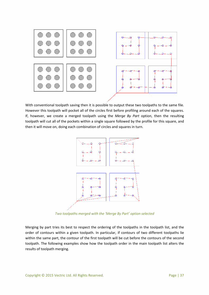
With conventional toolpath saving then it is possible to output these two toolpaths to the same file. However this toolpath will pocket all of the circles first before profiling around each of the squares. If, however, we create a merged toolpath using the Merge By Part option, then the resulting toolpath will cut all of the pockets within a single square followed by the profile for this square, and then it will move on, doing each combination of circles and squares in turn.
Two toolpaths merged with the ‘Merge By Part’ option selected
Merging by part tries its best to respect the ordering of the toolpaths in the toolpath list, and the order of contours within a given toolpath. In particular, if contours of two different toolpaths lie within the same part, the contour of the first toolpath will be cut before the contours of the second toolpath. The following examples show how the toolpath order in the main toolpath list alters the results of toolpath merging.

Copyright © 2015 Vectric Ltd. All Rights Reserved. Page | 38
Merged toolpath with toolpaths in the main toolpath list in order Toolpath A, Toolpath B and
Toolpath C
Merged toolpath with toolpaths in the main toolpath list in order Toolpath B, Toolpath C, and
Toolpath A
If the Merge By Part option is not selected then no attempt is made to preserve either the toolpath order or the order of contours within the same contour, this simply aims to get the same end result as quickly as possible. Because of this, it is best to use this option with caution, particularly if one of your toolpaths must be performed before the other, and you will be warned when using this option.
Toolpath Name Enter a name for the newly created merged toolpath.
Click on the Merge Toolpaths button. This creates a new toolpath. It does not modify the chosen
toolpaths.
Note: It is often a good idea to choose a name which describes the toolpaths to be merged. If one of these original toolpaths is then modified it is easier to recall which toolpaths need to be merged again.
Recalculating and Editing Merged Toolpaths Once a toolpath has been created using the merge toolpaths tool then it cannot be recalculated or edited. If you modify one of the original toolpaths then you must perform any merges again.
Feeds and Speeds It may be that the toolpaths to be merged have different feeds and speeds. Toolpath merging will automatically change the feeds and speeds for the different parts of the toolpath but you should check that your post –processor supports this.

Copyright © 2015 Vectric Ltd. All Rights Reserved. Page | 39
Create Job Sheet Job sheets contain a summary of the information you will need when you come to run the toolpaths for your project at your CNC machine. VCarve Pro will create a self-contained HTML document that can be viewed using most web browsers, including Internet Explorer, Chrome or Firefox. To create a job sheet for a given project, simply select Create Job Sheet from the Toolpaths menu and then select a filename and location to save the document. If your job contains multiple sheets, VCarve Pro will automatically create a Job Sheet for every sheet that contains toolpaths.
Each job sheet document comprises the following information:
Job Layout A thumbnail image representing the vectors on your current job / sheet, surrounded by an outer rectangle representing your material size.
Material Setup A summary of the important pieces of information you will need to correctly position and datum your work piece at you CNC machine. This includes the dimensions of the material block used within VCarve Pro to create and simulate your toolpaths. The home position from which your machine will start and return to. The clearance above the material for any rapid moves between plunges.
Toolpaths Summary A summary of each of the toolpaths in the file, including the name of the toolpath, the tool required and an estimate of how long it will take to cut.
Toolpaths List Details of each toolpath, including feed and plunge rates plus the intended spindle speed.

Copyright © 2015 Vectric Ltd. All Rights Reserved. Page | 40
Rough Machining Toolpath (3D) Rough Machining is used when carving 3D parts to clear away excess material when the part is too deep for the finishing tool to cut in a single pass.
Clicking on this icon opens the toolpath form shown to the right; the functions available within this are described below.
Tool Clicking the Select button opens the Tool Database allowing the selection of a tool for this operation. As with other toolpaths the Edit button allows the tool parameters to be changed for this specific toolpath.
Machining Limit Boundary The machining limit boundary is the area in which we perform the Rough machining. There are three options:
- Model Boundary. We use the combined boundaries of all the components in this job. This is the area of the composite model which has components on it. Note: this is not the boundary of the selected models.
- Material Boundary. We use the boundary of the entire material block.
- Selected Vectors. We use any selected vectors as the machining boundary.
Boundary Offset The center of the tool will go to the edge of the specified boundary. If you are machining a raised object, this often means that the tool won’t fully machine down the edge. This field is used to specify an offset to the selected machining boundary to increase its size to allow the tool to go past the actual edge if needed.
Machining Allowance The machining allowance is a virtual thickness which is added to the 3D model when the Roughing Toolpath is calculated. This ensures that the toolpath leaves some extra material on the roughed part.
This is beneficial for two main reasons, the first is that when roughing it tends to be done with relatively large tool and aggressive cuts and so is more prone (depending on the material) to chip, this “skin” helps to prevent the chipping affect the finished surface. The second reason is that most

Copyright © 2015 Vectric Ltd. All Rights Reserved. Page | 41
tools cut well when they are constantly removing material. Therefore leaving an allowance of material on ensures that there is always at least some material for the finishing toolpath to remove.
Z Level Strategy Z Level Roughing essentially uses a series of 2D Pocket toolpaths which take into account the 3D model and “hog-out” the material around it within the specified boundary. There are two settings that must be chosen to define this type of toolpath. The first box lets you choose the main direction of the cuts in the toolpath; either Raster X which fills each pocket with a raster pattern mainly parallel to the X axis or Raster Y which fills each pocket with a raster pattern parallel to the Y axis.
The second setting is the choice of Profile, this controls whether each level has a profile cut around its boundary or not and if so whether it cuts before the raster or after it. First does the profile before the Raster on each level, Last does the profile cut after the raster and None eliminates the Profile cut leaving only the raster pattern. These choices depend a lot on the material and tooling being used. For example, more brittle material may benefit from the profile first option to reduce chipping.
3D Raster Strategy The 3D Raster strategy is a 3D cut which passes over the whole model. This will leave a more even amount of material for the finish cut to remove but depending on the depth and style of the part it may take significantly longer to run. In shallower parts where the roughing is only taking one or two passes then this may be a better choice. For deeper parts then typically the Z Level rouging is a more efficient. There is only one option with this strategy is to define the main cutting direction. Raster X uses a raster pattern parallel to the X axis or Raster Y uses a raster pattern parallel to the Y axis.
Ramp Plunge Moves The cutter can be ramped over a distance into the pocket instead of plunging vertically. This approach reduces heat build-up that damages the cutter and also reduces the load on the spindle and z axis bearings
Safe Z The height above the job at which it is safe to move the cutter at rapid / max federate, this value can be changed by opening the Material Setup form.
Home Position This is the position that the tool will travel to and from before and after machining, this dimension can be changed in the Material Setup form.
Vector Selection This area of the toolpath page allows you to automatically select vectors to machine using the vector’s properties or position. It is also the method by which you can create Toolpath Templates to re-use your toolpath settings on similar projects in the future. For more information, see the sections Vector Selector and Advanced Toolpath Templates.
Name The name of the toolpath can be entered or the default name can be used.

Copyright © 2015 Vectric Ltd. All Rights Reserved. Page | 42
Finish Machining Toolpath (3D) Finish Machining is used to machine the final pass on the finished 3D part.
Clicking on this icon opens the toolpath form shown to the right; the functions available within this are described below.
Tool Clicking the Select button opens the Tool Database from which the required tool can be selected. Clicking the Edit button opens the Edit Tool form which allows the cutting parameters for the selected tool to be modified, without changing the master information in the database.
For most 3D Finishing cuts a Ball Nosed end mill is used with a reasonably small stepover (8 – 12% of the tool diameter is typical). Variations on this tool type such as a tapered Ball Nosed cutter will also work and may offer more strength with smaller tool sizes. The size of tool will depend on the size of the part and the detail within the 3D part. Use the preview function to check the finish quality and detail; if they are not to a high enough standard then the job may require smaller tooling or a smaller stepover. 3D cutting is always a tradeoff between time and quality and an optimum balance of tool size, finish quality, and time to cut. The choices made will always depend on an individual’s personal preferences or the specifications of the job.
Machining Limit Boundary The machining limit boundary defines the area cut by the Finish machining, there are three options:
- Model Boundary. We use the combined boundaries of all the components in this job. This is defined by the silhouette of the composite model. Note: This is the boundary of all visible components and will not take ignore selected objects.
- Material Boundary. We use the boundary of the entire material block. - Selected Vectors. We use any selected vectors as the machining boundary.
Area Machining Strategy There are two choices of the type of “fill pattern” that will be used to machine the area with the toolpath; Offset and Raster.
Offset Calculates an offset pattern projected onto the 3D surface and machined inside the selected vector(s). The cutting direction can be set to either Climb (CCW) or Conventional (CW) .

Copyright © 2015 Vectric Ltd. All Rights Reserved. Page | 43
Using Climb or Conventional cutting will largely be dictated by the material that is being machined. Talk to your tooling suppliers for details about what is most appropriate for your specific type of work.
Example of an Offset pattern
Raster Calculates a raster pattern projected onto the 3D surface and machined inside the selected vector(s), with control over Raster Angle - Between 0 and 90 degrees.
0 degrees is mainly parallel to the X axis 90 degrees is mainly parallel to the Y axis.
Example of a 3D Raster toolpath at 0 degrees
Safe Z The height above the job at which it is safe to move the cutter at rapid / max federate. This dimension can be changed by opening the Material Setup form.
Home Position Position from and to that the tool will travel before and after machining. This dimension can be changed by opening the Material Setup form.
Vector Selection This area of the toolpath page allows you to automatically select vectors to machine using the vector’s properties or layer.
Name The name of the toolpath can be entered or the default name can be used.

Copyright © 2015 Vectric Ltd. All Rights Reserved. Page | 44
Enhanced & Extended Toolpath Features This section details the improvements that have been made to features you will already be familiar with from earlier versions of VCarve Pro and includes the following:
• Profile Last Pass Allowance • Pocketing Enhancements - Pass Depth Control for Pocketing • Texture Toolpath Ramping • VCarve Start Points • Vector Selector Options • Toolpath Summary • Project toolpath onto 3D model • Preview Simulation Block Display
Profile Last Pass Allowance
Last Pass Allowance A separate allowance can be specified for the last pass in a profile toolpath. If this allowance is given, then all but the last pass will be undercut by the specified allowance with the final pass being the only pass which cuts to size.
The final pass (shown in blue) cuts to size. All previous passes (shown in red) are cut with a small allowance offset
If the Reverse direction button is checked then the cutting direction of the last pass is reversed. This feature is very useful if you want to minimize witness marks on the edge of profile cuts.
The last pass allowance will also take into account any allowance offset and so the two options can be used together.
The last pass allowance will respect any allowance offset also specified

Copyright © 2015 Vectric Ltd. All Rights Reserved. Page | 45
Pocketing Enhancements The 2D Pocketing Toolpath now has the ability to edit Pass Depths more precisely (see below) and will, where possible, respect the boundary start point on simple vector shapes when using the Offset strategy.
Pass Depth Control for Pocketing When a pocket toolpath is created, the Pass Depth value associated with the selected tool (part of the tool’s description in the Tool Database) is used to determine the number of passes needed to pocket down to the specified Cut Depth. However, by default VCarve Pro will also modify the tool step down by up to 15%, if by doing so it is able to reduce the total number of passes required to reach the desired cut depth. It is usually desirable to benefit from the significantly reduced machining time of cutting pockets to use less passes if possible. Nevertheless, there are some occasions where the exact step downs for a given profile pass needs to be more precisely controlled - when cutting into laminated material, for example. The Passes section of the Pocket Toolpath page indicates how
many passes will be created with the current settings. The Edit Passes… button will open a new
dialog that enables the specific number and height of passes to be set directly.
Specify Pass Depths The Pass Depths section at the top of the form shows a list of the current pass depths. The relative spacing of the passes is indicated in the diagram next to the list. Left click on a depth value in the list, or a depth line on the diagram, to select it. The currently selected pass is highlighted in red on the diagram.
To edit the depth of the selected pass, change the
value in the Depth edit box and click Apply .
The Delete button will delete the selected pass.
The Clear All Passes button will delete all the
passes.
To add a new pass, double left click at the approximate location in the passes diagram that you wish to add the pass. A new pass will be added and automatically selected. Edit the precise
Depth value if required and then click Apply .

Copyright © 2015 Vectric Ltd. All Rights Reserved. Page | 46
The Set Last Pass Thickness option will enable an edit box where you can specify the last pass in terms of the remaining thickness of material you wish to cut with the last pass (instead of in terms of its depth). This is often a more intuitive way to specify this value.
Pass Depth List Utilities This section of the form includes two methods for creating a set of passes in one go.
The first method simply sets the passes according to the Pass Depth property of the selected tool. By default, this is the method used by VCarve Pro when it creates profile passes initially. However, the Maintain exact tool pass depth option checked, VCarve Pro will not vary the step size to try and optimize the number of passes (see above).
The second method creates evenly spaced passes according to the value entered in the Number Of Passes edit box.
To apply either method click the associated Set Passes button to create the resulting set of pass
depths in the passes list and diagram.
Note: Setting the number of passes with either of these utilities will discard any custom passes you may have added.
Texture Toolpath Ramping In previous versions of VCarve Pro when using the Texture Toolpath strategy with the Use selected vectors as pattern option checked, the software would default to add a ramp entry and exit for the toolpath segment on each vector line. This is not always desirable, particularly when working with geometry created using the new Vector Texture Creation drawing tool. This has been changed so that when the Use selected vectors as pattern option is checked the default behaviour is to not add a ramp at each end but this is available as an addition checkbox. The toolpath without ramps is similar to profiling on the vectors but adds the ability to randomize the depths using the Max. Cut Depth control.
Checking the Ramp at start and end option will create a ramp in and out on each toolpath segment
VCarve Start Points The VCarve / Engraving toolpath strategy has had an option added to Use Vector Start Points. Checking the box for this will force the VCarving to start at the start point of the boundary vector and carve down into the material from there. If the shape is too deep for the toolpath to cut in a

Copyright © 2015 Vectric Ltd. All Rights Reserved. Page | 47
single pass the part of the toolpath that clears out the material will still be cut with vertical plunges into the material, only the actual v-carve will respect the start point. This can help reduce the load and as such potential marking of the finished part created by the tool vibrating when plunging into a deep area of the cut.
The Use Vector Start Points option in the VCarving can reduce the load and vibration on the tool when entering the material
Vector Selector Options When activating the Vector Selector option for a toolpath the form will remember the last set of values and choices made making it quicker in some cases to assign similar choices to the new toolpath. It will not retain the Associate with Toolpath option, this will need to be switched on manually for each new toolpath.
Toolpath Summary When you click on the Toolpath Summary icon the software will only display the visible toolpaths (those with a check mark in the box next to them). This allows you to customize the selection of toolpaths you interrogate. However, if you have no visible toolpaths it will default to show all of the calculated toolpaths in the list.
Project toolpath onto 3D model All 2D and 2.5 Toolpaths in VCarve Pro have had the Project toolpath onto 3D model option added at the base of each Toolpath form. This option is only available if you have imported 3D Models.
If this option is checked then after the toolpath has been calculated, it will be projected (or ‘dropped’) down in Z onto the surface of the 3D model. The depth of the original toolpath below the surface of the material will be used as the projected depth below the surface of the model. This can be very effective for machining text onto a curved surface but will only be effective for relatively shallow shapes. If the shape that is being projects onto has steep areas then the result is likely to be “stretched” and so not look good, use the Toolpath Preview to carefully check the result of using this option to ensure it looks how you want it to before machining.
Preview Simulation Block Display In previous versions of VCarve Pro because there was not support for 3D model import then the software would retain the Preview Simulation block in the 3D View when the Preview form was closed. This will still be the case if you are working on a job with only vectors and 2D and 2.5D toolpaths. However if there is a Composite Model (3D Components) visible in the 3D View then VCarve Pro will undrawn the preview block when the form is closed and display the 3D model instead. Going back into the Toolpath Preview function will re-draw the preview block at the same state it was in when exiting the form.

Copyright © 2015 Vectric Ltd. All Rights Reserved. Page | 48
Miscellaneous Improvements This section details the improvements that have been made to features you will already be familiar with from earlier versions of VCarve Pro and includes the following:
• Increment and Save • Bitmap Import from PDF Files • 64-bit Build • SketchUp 2015 Support • Document Variables
Increment and Save When working towards a particular design goal or iterating through several designs variations to see which one works best, it is often handy to keep tagged copies of the same file at different stages of the design process. The new Increment and Save option under the File menu will automatically append and number to the current filename and save a separate copy of your file, rather than simply saving over the top of your previously saved file. It is a convenient, automated form of Save As… specifically to deal with the common process of saving a set of incremental changes to the same file. The short cut key Ctrl + Alt + S will perform this function as well.
Bitmap Import from PDF Files PDF files are able to store both vector artwork, as well as bitmap images. VCarve Pro will now import both of these types of artwork from a PDF document. If the document has one page, the images and/or vectors will be imported onto a layer with the same name as the document. If the document has multiple pages, the vectors and/or images in the document will be imported and placed on a single layer per page, names Page 1, Page 2 etc. The PDF import function now also has a progress bar.
64-bit Build The new version of VCarve Pro had installers for both 32-bit and 64-bit computers. The installer will detect and continue to install the 32-bit version on non-64-bit machines but will automatically install the 64-bit version on 64-bit machines. The Help->about menu option will report the 64-bit version, if you ever need to verify which version you are running. The 64-bit build will allow the software to make use of all the RAM on the PC, this will allow the processing of very long toolpaths, complex nesting jobs and import and export of much larger 3D mesh (STL, OBJ etc.) files.
SketchUp 2015 Support The import filters for SketchUp *.SKP files (both 2D vector and 3D mesh data) have been updated to be compatible with files saved from SketchUp 2015.

Copyright © 2015 Vectric Ltd. All Rights Reserved. Page | 49
Document Variables Document Variables provide a mechanism for defining values that can be used in VCarve Pro’s Calculation Edit Boxes. They can either be created in the Document Variables dialog which is accessible under the Edit menu, or created from any Calculation Edit Box which supports variables by right clicking and selecting ‘Insert New Document Variable’ from the Popup Menu.
Naming Document Variables New Document Variable names must begin with a letter and then may consist of letter, number and underscore characters. Once created, they may be edited in the table beneath the New Variable section.
Variables can be exported to a text file and imported into another job. When importing, any existing variable
values with the same name will be replaced.
Deleting Document Variables Variables may be deleted but only if they’re not being used in any toolpath calculations. If any toolpath creation form is open then any existing variables cannot be deleted.
Using Document Variables Once created a Document Variable may be used in any Calculation Edit Box by enclosing its name within a pair of curly braces as illustrated in the figure below.
Right clicking in a Calculation Edit Box provides a Popup Menu that provides shortcuts for creating new Variables and inserting existing variables into the Edit Box.
Once a Document Variable has been created from the Popup Menu it will be inserted into the Edit Box.

Copyright © 2015 Vectric Ltd. All Rights Reserved. Page | 50