Embed Size (px)
Citation preview

MODEL : VC50
Laney
USER MANUAL
: VC100: VH100R
Alliance

IMPORTANT SAFETY INSTRUCTIONS
WARNING: When using electric products, basic cautions should always be followed, including the following.
1. Read all safety and operating instructions before using this product2. All safety and operating instructions should be retained for future reference3. Obey all cautions in the Operating instructions and on the back of the unit4. All operating instructions should be followed5. This product should not be used near water, i.e. a bathtub, sink, swimming pool, wet basement, etc.6. This product should be located so that its position does not interfere with its proper ventilation. It should not
be placed flat against a wall or placed in a built up enclosure that will impede the flow of cooling air.7. This product should not be placed near a source of heat such as stove, radiator, or another heat producing
amplifier.8. Connect only to a power supply of the type marker on the unit adjacent to the power supply cord.9. Never break off the ground pin on a power supply cord.10. Power supply cords should always be handled carefully. Never walk or place equipment on power supply
cords. Periodically check cords for cuts or signs of stress, especially at the plug and the point where thechord exits the unit.
11. The power supply cord should be unplugged when the unit is to be unused for long periods of time.12. If this product is to be mounted in an equipment rack, rear support should be provided.13. The user should allow easy access to any mains plug, mains coupler and mains switch used in conjunction
with this unit thus making it readily operable.14. Metal parts can be cleaned with a damp cloth. The vinyl covering used on some units can be cleaned with
a damp cloth or ammonia based household cleaner if necessary. Disconnect the unit from the powersupply before cleaning.
15. Care should be taken so that objects do not fall and liquids are not spilled into the unit through anyventilation holes or openings. On no account place drinks on the unit.
16. A qualified service technician should check the unit if:The power cord has been damagedAnything has fallen or spilled into the unitThe unit does not appear to operate correctlyThe unit has been dropped or the enclosure damaged.
17. The user should not attempt to service the equipment. All service work is done by a qualifiedservice technician.
18. Exposure to extremely high noise levels may cause a permanent hearing gloss. Individuals varyconsiderably in susceptibility to noise induced hearing loss, but nearly everyone will lose some hearing ifexposed to sufficiently intense noise for a sufficient time. The U.S. Government's Occupational Safety andHealth Administration (OSHA) has specified the following permissible noise level exposure.
Duration Per Day In Hours Sound Level dBA, slow response8 90
6 92
4 95
3 97
2 100
1 ½ 102
1 105
½ 110
¼ or less 115
According to OSHA, any exposure in excess of the above permissible limits could result in some hearing loss. Ear
plugs or protectors in the ear canals or over the ears must be worn when operating this amplification system in
order to prevent a permanent hearing loss if exposure exceeds the limits set forth above. To ensure against
potentially dangerous exposure to high sound pressure levels it is recommended that all persons exposed to
equipment capable of producing high sound pressure levels such as this amplification system be protected by
SAVE THESE INSTRUCTIONS

Dieses Symbol soll den Anwender vor unsolierten gefahrlichen Spannungen innerhalb des Gehauses warnen, die vonAusreichender Starke sind, um einen elektrischen Schlag verursachen zu konnen.
Dieses Symbol soll den Benutzer auf wichtige Instruktionen in der Bedienungsanleitung aufmerksammachen, die Handhabung und Wartung des Produkts betreffen.
Um einen elektrischen Schlag oder Feuergefahr zu vermeiden, sollte dieses Gerat nicht dem Regen oder Feuchtigkeitausgesetzt werden. Vor Inbetriebnahme unbedingt die Bedienungsanleitung lesen.
Risiko - Elektrischer Schlag! Nicht offen!
Um das Risiko eines elektrischen Schlages zu vermeiden, nicht die Abdeckung enfernen. Es befinden sich keineTeile darin, die vom Anwender repariert werden Konnten. Reparaturen nur von qualifiziertem Fachpersonaldurchfuhren lassen
ACHTUNG
VORSICHT:
VORSICHT:
!
Este simbolo tiene el proposito de alertar al usuario de la presencia de “(voltaje) peligroso” que no tiene aislamiento dentrode la caja del producto que puede tener una magnitud suficiente como para constituir riesgo de corrientazo
Este simbolo tiene el proposito de alertar al usario de la presencis de instruccones importantes sobre laoperacion y mantenimiento en la literatura que viene con el producto
Para evitar corrientazos o peligro de incendio, no deja expuesto a la lluvia o humedad este aparato Antes de usar esteaparato, lea mas advertcias en la guia de operacion
Riesgo de corrientazo - no abra
Para disminuir el riesgo de carrientazo, no abra la cubierta. No hay piezas adentro que el pueda reparar. Deje todomantenimiento a los tecnicos calificadod
ADVERTENCIA:
PRECAUCION:
PRECAUCION:
!
Ce symbole est utilise pur indiquer a l’utilisateur de ce produit de tension non-isolee dangereuse pouvant etre d’intensitesuffisante pour constituer un risque de choc electrique.
Ce symbole est utilise pour indiquer a l’utilisanter qu’il ou qu’elle trouvera d’importantes instrucions sur l’utilisationet l’entrerien (service) de l’appareil dans la litterature accompagnant le produit
Afin de prevenir les risques de decharge electrique ou de feu, n’exposez pas cet appareil a la pluie ou al’humidite. Avant d’utiliser cet appareil, lisez les avertissements supplentaires situes dans le guide.
Risques de choc electrique - NE PAS OUVIRIR
Afin de reduire le risque de choc electrique, ne pas enlever le couvercle. Il ne se trouve a l’interieur aucune piecepouvant etre reparee par l’utilisateur. Confier l’entretien a un personnel qualifie.
AVERTISSEMENT:
ATTENTION:
ATTENTION:
!
Intended to alert the user to the presence of uninsulated “dangerous voltage” within the product’s enclosure that may be ofsufficient to constitute a risk of electrical shock to persons
Intended to alert the user of the presence of important operating and maintainance (servicing)instructions in the literature accompanying the product
To prevent electrical shock or fire hazard, do not expose this appliance to rain or moisture. Before using this appliance pleaseread the operating instructions for further warnings
Risk of electrical shock - DO NOT OPEN
To reduce the risk of electrical shock, do not remove the cover. No user servicable parts inside. Refer servicing toqualified service personnel.
WARNING:
CAUTION:
CAUTION:
!
Laney

Care of your amplifier will prolong it's life.....and yours!. If you follow these guidelines your equipment will give youyears of playing pleasure
Laney
After unpacking your amplifier check that it is factory fitted with a three pin 'grounded' (or earthed) plug. Before plugging intothe power supply ensure you are connecting to a grounded earth outlet.
If you should wish to change the factory fitted plug yourself, ensure that the wiring convention applicable to the country wherethe amplifier is to be used is strictly conformed to. As an example in the United Kingdom the cable colour code forconnections are as follows.
EARTH OR GROUND - GREEN/YELLOWNEUTRAL - BLUELIVE - BROWN
220V
LaneyCongratulations on your decision to purchase a amplifier.
products are designed with ease of operation as a primary objective, however to ensure you derive the best from yournew amplifier, it is important you take time to read this user manual and to familiarise yourself with the control functions andfacilities available
Laney
Laney
INTRODUCTION
BEFORESWITCHING ON
This manual has been written for easy access of information. The front and rear panels of each unit are graphically illustrated,with each control and feature numbered. For a description of the function of each control feature, simply check the numberwith the explanations adjacent to each panel.
Your valve amplifier has undergone a thorough two stage, pre-delivery inspection, involving actual play testing, as wellas valve burn in. Valves are the most important component in your valve amp. However they are also the most fragilecomponent. The glass envelope and valve filaments can easily be damaged in transit without any apparent signs of damage tothe box, amp or valves. Valve damage is however quite simple to diagnose and even more simple to remedy. These proceduresare explained later in this manual..
LaneyLaney
When you first recieve your valve amp, follow these simple procedures:
(i) Ensure that the amplifier is set at the correct voltage for the country it is to be used in.
(ii) Ensure that the speaker is connected to the appropriate socket.
(iii) Connect your instrument with a high quality shielded instrument cable. Use of cheap cables will compromise the soundof your instrument and your amplifier.
Laney
If there is a problem with your valve amplifierLaney
DON'T DO
PHONE YOUR DEALER!
1

MODEL VC50/VC100 & VH100R
BLUES LEAD
ROCK LEAD
CLEAN
CLEAN CRUNCH
2
BASS MIDDLE TREBLE REVERB EFFECTS
5
0
1
2
3
4 6
7
8
9
10
5
0
1
2
3
4 6
7
8
9
10
5
0
1
2
3
4 6
7
8
9
10
5
0
1
2
3
4 6
7
8
9
10
1
2
3
5
0
1
2
3
4 6
7
8
9
10
5
0
1
2
3
4 6
7
8
9
10
5
0
1
2
3
4 6
7
8
9
10
5
0
1
2
3
4 6
7
8
9
10
5
0
1
2
3
4 6
7
8
9
10
5
0
1
2
3
4 6
7
8
9
10
5
0
1
2
3
4 6
7
8
9
10
1
2
3
5
0
1
2
3
4 6
7
8
9
10
5
0
1
2
3
4 6
7
8
9
10
5
0
1
2
3
4 6
7
8
9
10
5
0
1
2
3
4 6
7
8
9
10
VOLUME BRIGHT VOLUME RESONANCE
PRESENCE
STANDBY POWER
BASS MIDDLE TREBLE REVERB EFFECTSGAIN VOLUMEDRIVE
CHANNEL
5
0
4 6
7
8
9
10
5
0
4 6
7
8
9
10
DRIVE
INPUT
HI
LOBoth HI and LOinputs should beexperimented withto obtain the soundyou are looking for.
INPUT
HI
LOBoth HI and LOinputs should beexperimented withto obtain the soundyou are looking for.
INPUT
HI
LOBoth HI and LOinputs should beexperimented withto obtain the soundyou are looking for.
BASS MIDDLE TREBLE REVERB EFFECTS
5
0
1
2
3
4 6
7
8
9
10
5
0
1
2
3
4 6
7
8
9
10
5
0
1
2
3
4 6
7
8
9
10
5
0
1
2
3
4 6
7
8
9
10
1
2
3
5
0
1
2
3
4 6
7
8
9
10
5
0
1
2
3
4 6
7
8
9
10
5
0
1
2
3
4 6
7
8
9
10
5
0
1
2
3
4 6
7
8
9
10
5
0
1
2
3
4 6
7
8
9
10
5
0
1
2
3
4 6
7
8
9
10
5
0
1
2
3
4 6
7
8
9
10
1
2
3
5
0
1
2
3
4 6
7
8
9
10
5
0
1
2
3
4 6
7
8
9
10
5
0
1
2
3
4 6
7
8
9
10
5
0
1
2
3
4 6
7
8
9
10
VOLUME BRIGHT VOLUME RESONANCE
PRESENCE
STANDBY POWER
BASS MIDDLE TREBLE REVERB EFFECTSGAIN VOLUMEDRIVE
CHANNEL
5
0
4 6
7
8
9
10
5
0
4 6
7
8
9
10
DRIVE
INPUT
HI
LOBoth HI and LOinputs should beexperimented withto obtain the soundyou are looking for.
ROCK RHYTHM
BASS MIDDLE TREBLE REVERB EFFECTS
5
0
1
2
3
4 6
7
8
9
10
5
0
1
2
3
4 6
7
8
9
10
5
0
1
2
3
4 6
7
8
9
10
5
0
1
2
3
4 6
7
8
9
10
1
2
3
5
0
1
2
3
4 6
7
8
9
10
5
0
1
2
3
4 6
7
8
9
10
5
0
1
2
3
4 6
7
8
9
10
5
0
1
2
3
4 6
7
8
9
10
5
0
1
2
3
4 6
7
8
9
10
5
0
1
2
3
4 6
7
8
9
10
5
0
1
2
3
4 6
7
8
9
10
1
2
3
5
0
1
2
3
4 6
7
8
9
10
5
0
1
2
3
4 6
7
8
9
10
5
0
1
2
3
4 6
7
8
9
10
5
0
1
2
3
4 6
7
8
9
10
VOLUME BRIGHT VOLUME RESONANCE
PRESENCE
STANDBY POWER
BASS MIDDLE TREBLE REVERB EFFECTSGAIN VOLUMEDRIVE
CHANNEL
5
0
4 6
7
8
9
10
5
0
4 6
7
8
9
10
DRIVE
INPUT
HI
LOBoth HI and LOinputs should beexperimented withto obtain the soundyou are looking for.
Reverb & Effectlevels should beset to required
Reverb & Effectlevels should beset to required
Reverb & Effectlevels should beset to required
Reverb & Effectlevels should beset to required
Reverb & Effectlevels should beset to required

20
3
MODEL VC50/VC100/VH100R
BASS MIDDLE TREBLE REVERB EFFECTS
5
0
1
2
3
4 6
7
8
9
10
5
0
1
2
3
4 6
7
8
9
10
5
0
1
2
3
4 6
7
8
9
10
5
0
1
2
3
4 6
7
8
9
10
1
2
3
5
0
1
2
3
4 6
7
8
9
10
5
0
1
2
3
4 6
7
8
9
10
5
0
1
2
3
4 6
7
8
9
10
5
0
1
2
3
4 6
7
8
9
10
5
0
1
2
3
4 6
7
8
9
10
5
0
1
2
3
4 6
7
8
9
10
5
0
1
2
3
4 6
7
8
9
10
1
2
3
5
0
1
2
3
4 6
7
8
9
10
5
0
1
2
3
4 6
7
8
9
10
5
0
1
2
3
4 6
7
8
9
10
5
0
1
2
3
4 6
7
8
9
10
VOLUME BRIGHT VOLUME RESONANCE
PRESENCE
STANDBY POWER
BASS MIDDLE TREBLE REVERB EFFECTSGAIN VOLUMEDRIVE
INPUT
HI
LO
CHANNEL
5
0
4 6
7
8
9
10
5
0
4 6
7
8
9
10
DRIVE
EXPLANATION OF TERMS
1
2 3 4 5 61a 7 11 128 9 10 14
17
15
161819
13
LO INPUT:
VOLUME:
BRIGHT SWITCH:
DRIVE:
VOLUME:
DRIVE SWITCH:
BASS:
MIDDLE:
TREBLE:
REVERB:
EFFECTS:
CHANNEL SWITCH:
RESONANCE:
STANDBY:
This input is attenuated down approximately 6dB from the high input. It is useful in obtainingoutput that is "tight" not "mushy" from high gain humbucker type pickups.
Adjusts the overall volume of the clean channel
Adds brightness and sparkle to the upper frequencies of the clean and clean drivechannel
This pot controls the amount of 'Valve" drive applied to the circuit.
Sets the overall volume level of the clean channel drive sound.
Engages the clean channel drive sound (Also footswitchable)
Controls the low frequency EQ in the pre amplifier.
Controls the mid frequency EQ in the pre amplifier.
Controls the high frequency EQ in the pre amplifier
Controls the level of reverb assigned to each channel
Controls the signal level upon its return from an external processor and blends it to the desiredlevel with the main signal.
Selects the required channel which is displayed by an illuminated indicator. The upperchannel produces the clean tone and mild overdrive that is reminiscent of a sixties American valve combo. Thelower channel produces the more substantial overdrive and distortion that is associated with British valvestacks.
Adjusts the 'damping' control of the amplifier speaker enclosure, thereby controlling the'tightness' of the bass responce. This effect is very cabinet dependant so the switch should be adjusted to taste.
This switch enables/disengages the high voltage DC to the valves, switching the amplifier from a'wait state' to an 'active state'. The AC voltage to the heaters is not effected by this switch so that an instant onof the amplifier is achieved when switching to an active state, so long as the POWER SWITCH has remained inthe ON position. Always switch the amplifier to the 'STANDBY' before turning the main power switch off.This will prolong valve life
10
11
9
8
1a
2
3
4
5
6
7
12
14
11 13
1b
N.B. It should be noted that the layout of the control panel is reversed and inverted on the VH100R when compared to the layout diagrams

393837
1b
20
MODEL VC50/VC100/VH100R
PRESENCE:
VOLUME
GAIN:
DRIVE SWITCH
DRIVE:
HI INPUT:
Controls the high frequency material in the power amplifier.
Adjusts the overall volume of the overdrive channel
Adjusts the input level of the overdrive channel.
Allows activation of the overdrive section from the front panel.
Controls the amount of valve overdrive. The overdrive is applied to the circuit just prior to the gaincontrol. The drive is engaged only when the drive switch (19) is on. The drive may be operated by the switch orremotely by the footswitch (FS4) connected on the rear panel.
This input provides maximum gain from the instrument to the pre amp. It is extremely useful forguitars with single coiled or low gain humbucker type pickups. Use of high gain pickups in this input may drivethe pre amp to severely, causing a "mushy" output.
:
:
16
19
18
17
4
VC50/VC100 BACK PANEL
25 35
404142
29 3433323128272621 242322 3630
LINE
POWER PREAMP AMP
IN OUTPOWER FUSE HT FUSE
EXTENSIONCABINET
INTERNALCABINET
4 OHM 8 OHMFOOTSWITCH
6L65881 EL34
BIASINSERT
SIDECHAIN
BYPASS
RETURNLEVEL
RETURN SEND
INSERT EFFECTS LOOP
SEND RETURN RETURN RETURN SEND
A+BEFFECTS LOOP
OVERDRIVRE CHANNEL B CLEAN CHANNEL A
VH100R BACK PANEL
POWER FUSEHT FUSELINE
POWERAMP
PREAMP
IN OUT6L65881EL34
BIAS
FOOTSWITCHRETURNLEVEL
INSERTSIDE
CHAINBYPASS RETURNSEND
INSERTEFFECTS LOOP
SEND RETURN RETURN RETURN SEND
A+BEFFECTS LOOP
OVERDRIVRE CHANNEL BCLEAN CHANNEL A
SPEAKERS
1x16 ohm
2x16 ohm
1x8 ohm2x8 ohm
1x4 ohm
21
22
POWER CONNECTOR:
POWER FUSE:
This is where the mains cable attaches.
This fuse protects the AC power of the overall amplifier. Use ONLY the correct size and ratingof fuse as specified on the panel. If a fuse blows or fails and a replacement of the same size and rating is installedand it in turn blows, the amplifier has suffered a malfunction internally and needs immediate service from aqualified technician DO NOT TRY USING A FUSE OF HIGHER RATING.
20
BASS MIDDLE TREBLE REVERB EFFECTS
5
0
1
2
3
4 6
7
8
9
10
5
0
1
2
3
4 6
7
8
9
10
5
0
1
2
3
4 6
7
8
9
10
5
0
1
2
3
4 6
7
8
9
10
1
2
3
5
0
1
2
3
4 6
7
8
9
10
5
0
1
2
3
4 6
7
8
9
10
5
0
1
2
3
4 6
7
8
9
10
5
0
1
2
3
4 6
7
8
9
10
5
0
1
2
3
4 6
7
8
9
10
5
0
1
2
3
4 6
7
8
9
10
5
0
1
2
3
4 6
7
8
9
10
1
2
3
5
0
1
2
3
4 6
7
8
9
10
5
0
1
2
3
4 6
7
8
9
10
5
0
1
2
3
4 6
7
8
9
10
5
0
1
2
3
4 6
7
8
9
10
VOLUME BRIGHT VOLUME RESONANCE
PRESENCE
STANDBY POWER
BASS MIDDLE TREBLE REVERB EFFECTSGAIN VOLUMEDRIVE
INPUT
HI
LO
CHANNEL
5
0
4 6
7
8
9
10
5
0
4 6
7
8
9
10
DRIVE
2 3 4 5 61a 7 11 128 9 10 14
17
15
161819
13
1b
31
25
40 4241
VH100R BACK PANELVH100R BACK PANEL
5
MODEL VC50/VC100/VH100R
1
23
24
32
30
29
26
27
28
25 35 39383729 3433323128272621 242322 3630
LINE
POWER PREAMP AMP
IN OUTPOWER FUSE HT FUSE
EXTENSIONCABINET
INTERNALCABINET
4 OHM 8 OHMFOOTSWITCH
6L65881 EL34
BIASINSERT
SIDECHAIN
BYPASS
RETURNLEVEL
RETURN SEND
INSERT EFFECTS LOOP
SEND RETURN RETURN RETURN SEND
A+BEFFECTS LOOP
OVERDRIVRE CHANNEL B CLEAN CHANNEL A
VC50/VC100 REAR PANEL
POWER FUSEHT FUSELINE
POWERAMP
PREAMP
IN OUT6L65881EL34
BIAS
FOOTSWITCHRETURNLEVEL
INSERTSIDE
CHAINBYPASS RETURNSEND
INSERTEFFECTS LOOP
SEND RETURN RETURN RETURN SEND
A+BEFFECTS LOOP
OVERDRIVRE CHANNEL BCLEAN CHANNEL A
SPEAKERS
1x16 ohm
2x16 ohm
1x8 ohm2x8 ohm
1x4 ohm
HT FUSE:
EXTENSION SPEAKER SOCKET:
IMPEDANCE SELECTOR SWITCH:
INTERNAL SPEAKER SOCKET:
POWER AMP/LINE IN:
POWER AMP/LINEOUT:
BIAS SWITCH:
FOOTSWITCH SOCKET:
RETURN LEVEL:
RETURN SOCKET:
FX MODE SWITCH:
FX SEND SOCKET:
FX LOOP SEND (OVERDRIVE CHANNEL):
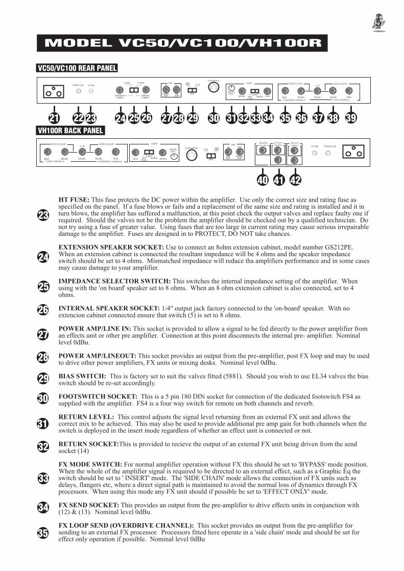
This fuse protects the DC power within the amplifier. Use only the correct size and rating fuse asspecified on the panel. If a fuse blows or fails and a replacement of the same size and rating is installed and it inturn blows, the amplifier has suffered a malfunction, at this point check the output valves and replace faulty one ifrequired. Should the valves not be the problem the amplifier should be checked out by a qualified technician. Donot try using a fuse of greater value. Using fuses that are too large in current rating may cause serious irrepairabledamage to the amplifier. Fuses are designed in to PROTECT, DO NOT take chances.
Use to connect an 8ohm extension cabinet, model number GS212PE.When an extension cabinet is connected the resultant impedance will be 4 ohms and the speaker impedanceswitch should be set to 4 ohms. Mismatched impedance will reduce tha amplifiers performance and in some casesmay cause damage to your amplifier.
This switches the internal impedance setting of the amplifier. Whenusing with the 'on board' speaker set to 8 ohms. When an 8 ohm extension cabinet is also connected, set to 4ohms.
1/4" output jack factory connected to the 'on-board' speaker. With noextencion cabinet connected ensure that switch (5) is set to 8 ohms.
This socket is provided to allow a signal to be fed directly to the power amplifier froman effects unit or other pre amplifier. Connection at this point disconnects the internal pre- amplifier. Nominallevel 0dBu.
This socket provides an output from the pre-amplifier, post FX loop and may be usedto drive other power amplifiers, FX units or mixing desks. Nominal level 0dBu.
This is factory set to suit the valves fitted (5881). Should you wish to use EL34 valves the biasswitch should be re-set accordingly.
This is a 5 pin 180 DIN socket for connection of the dedicated footswitch FS4 assupplied with the amplifier. FS4 is a four way switch for remote on both channels and reverb.
This control adjusts the signal level returning from an external FX unit and allows thecorrect mix to be achieved. This may also be used to provide additional pre amp gain for both channels when theswitch is deployed in the insert mode regardless of whether an effect unit is connected or not.
This is provided to recieve the output of an external FX unit being driven from the sendsocket (14)
For normal amplifier operation without FX this should be set to 'BYPASS' mode position.When the whole of the amplifier signal is required to be directed to an external effect, such as a Graphic Eq theswitch should be set to ' INSERT' mode. The 'SIDE CHAIN' mode allows the connection of FX units such asdelays, flangers etc, where a direct signal path is maintained to avoid the normal loss of dynamics through FXprocessors. When using this mode any FX unit should if possible be set to 'EFFECT ONLY' mode.
This provides an output from the pre-amplifier to drive effects units in conjunction with(12) & (13). Nominal level 0dBu.
This socket provides an output from the pre-amplifier forsending to an external FX processor. Processors fitted here operate in a 'side chain' mode and should be set foreffect only operation if possible. Nominal level 0dBu
34
35
33

Ancillary Connection Examples
LINE
POWER PREAMP AMP
IN OUTPOWER FUSE HT FUSE
EXTENSIONCABINET
INTERNALCABINET
4 OHM 8 OHMFOOTSWITCH
6L65881 EL34
BIASINSERT
SIDECHAIN
BYPASS
RETURNLEVEL
RETURN SEND
INSERT EFFECTS LOOP
SEND RETURN RETURN RETURN SEND
A+BEFFECTS LOOP
OVERDRIVRE CHANNEL B CLEAN CHANNEL A
FX.C
FX.A
FX.B
EG. Slap back delay
EG. ChorusEG. Multi-FX unitin 'side chain' mode
or Graphic EQ in insert mode
Laney
LINE
POWER PREAMP AMP
IN OUTPOWER FUSE HT FUSE
EXTENSIONCABINET
INTERNALCABINET
4 OHM 8 OHMFOOTSWITCH
6L65881 EL34
BIASINSERT
SIDECHAIN
BYPASS
RETURNLEVEL
RETURN SEND
INSERT EFFECTS LOOP
SEND RETURN RETURN RETURN SEND
A+BEFFECTS LOOP
OVERDRIVRE CHANNEL B CLEAN CHANNEL A
VC50/VC100 REAR PANEL
34 35 383733 36
40 4241
VH100R BACK PANELVH100R BACK PANEL
6
MODEL VC50/VC100/VH100R
25 3929 323128272621 242322
39
38
42
41
40
37
36
30
POWER FUSEHT FUSELINE
POWERAMP
PREAMP
IN OUT6L65881EL34
BIAS
FOOTSWITCHRETURNLEVEL
INSERTSIDE
CHAINBYPASS RETURNSEND
INSERTEFFECTS LOOP
SEND RETURN RETURN RETURN SEND
A+BEFFECTS LOOP
OVERDRIVRE CHANNEL BCLEAN CHANNEL A
SPEAKERS
1x16 ohm
2x16 ohm
1x8 ohm2x8 ohm
1x4 ohm
FX LOOP RETURN (Overdrive Channel):
FX LOOP RETURN A+B:
FX LOOP RETURN (Clean Channel):
FX LOOP SEND (Clean Channel):
SPEAKER OUTPUTS (VH100R):
This socket is provided to accept the output of an externalFXprocessor being driven from (15). The return level mix is controlled via the front panel effects level control.
This socket is provided for use when a single effects unit is to be used, on bothchannels, at different mix levels, via the front panel effect level controls. In this set up the effects units may bedriven from either channel send sockets.
This socket is provided to accept the output of an external effectsprocessor being drive from (19). The return level mix is controlled via the front panel effects control.
This socket provides an output from the pre-amplifier for sending to anexternal FX processor. Processors connected here operate in the 'side chain' mode so should be set for effectonly operation if possible. Nominal level 0dBu.
A series of five 1/4" output jacks allows the user to correctly interface theoutput impedance of the amplifier to the selected speaker enclosures. In following the cabinet impedanceinformation printed around the appropriate jack or jacks, correct operation and impedance matching is ensured.Mismatched impedance will reduce the amplifiers performance and in some cases can cause irreparable damage.
LINE
POWER PREAMP AMP
IN OUTPOWER FUSE HT FUSE
EXTENSIONCABINET
INTERNALCABINET
4 OHM 8 OHMFOOTSWITCH
6L65881 EL34
BIASINSERT
SIDECHAIN
BYPASS
RETURNLEVEL
RETURN SEND
INSERT EFFECTS LOOP
SEND RETURN RETURN RETURN SEND
A+BEFFECTS LOOP
OVERDRIVRE CHANNEL B CLEAN CHANNEL A
FX.A & B FX. A&BGraphic EQ
PROCESSORS ONLYPROCESSORS
Overall Side Chain FX Units Single FX unit used onboth channels with frontpanel level controls.
Overall Graphic EQ
Slavepower amplifier
In via poweramp socket
Nominal Level 0dBu

7
USEFUL HINTS AND TIPS
The following hints and tips are provided so that you can get the best performance out of your valve amplifier. These are onlyguidelines and should be adapted for your own preferences:-
Valve amplifiers take a short time to 'warm up' to optimum operating temperature. To get optimum performance out of your ampallow the amplifier to 'warm up' for three mins. before you begin playing.
The position of an amplifier in a room has an effect upon the overall sound characteristics. If you wish to increase the bassresponce of your amplifier place the amplifier on the floor. If you wish to reduce the bass response of your amplifier place theamplifier on a stand.
Do not place you amplifier hard up against a wall as this will reduce the air circulating around the back of the unit and may result inoverheating.
Laney
1:
2:
3:
4: Connecting your guitar to either the 'HI' or 'LO' input has an effect on the sound, regardless of the guitar type/pickupconfiguration. The 'HI' socket provides more gain. The 'LO' socket provides a lower gain. You should experiment with both inputsto find the one which suits your guitar, style of playing and gives you the most tonally pleasing results.
VALVE REPLACEMENT AND TROUBLE SHOOTINGPS
VALVE REPLACEMENT AND TROUBLE SHOOTING
The valves in your new valve amplifier will eventually need replacing due to wear, this is normal with valve amps. In most instancesyou should be able to effect valve replacement yourself without incurring the costs of a service engineer. Following are some of themost likely symptoms of valve malfunction and a suggested method of correction.
Normally valve amps give optimum performance when fitted with matched sets of output valves as factory fitted to all valveamps. NB: Damage will not occur by not fitting matched sets although the amplifiers performance may be impaired.
Laney
VALVE IDENTIFICATION
SOLUTION 1
SYMPTOM 1
Check time delay POWER FUSE and replace if necessary:-100-120 Volts 5 Amp time delay220-240 Volts 2 Amp time delay
Amp connections have been performed correctly but power light fails to illuminate
SOLUTION 2
SYMPTOM 2
Power light illuminates, no sound out put
Check secondary HT fuse and if blown replace with 1 amp time delay
5: When using the 'BRIGHT SWITCH' on the amplifier keep in mind that it has a greater audible effect the lower the amount ofdistortion produced by the preamplifier. At some distortion levels the 'BRIGHT SWITCH' may appear to have no effect at all.
1 2
3 4
5 6 7 8 9 10
Pre Amplifierinput valves6xECC83
Power Aamplifieroutput valves4x5881 matched quartet
1 First gain stage-Clean channel2 2nd gain stage-Clean channel3 First gain stage Drive channel4 2nd gain stage Drive channel5 3rd gain stage Drive channel6 Power driver stage
7 & 8 2x5881 Output valves for VC507,8,9&10 4x5881 Output valves for VC100/VH100R.
VALVE FUNCTIONS

SOLUTION 5
SYMPTOM 5
No clean channel, drive channel OK.
Replace pre amp valve No. 3 & 4
Secondary HT fuse (1Amp time delay) blows repeatedly. This is a strong indication of a damaged output valve. The valvefunction chart shows the valve layout and the function each performs.
Replace the secondary fuse and turn on the power WITH STANDBY ENGAGED. View the output valves. If one of thevalves fails to light up, replace that valve. If both of the output valves are lit dimily, look directly at the output valves abddisengage standby. If one of the valves flashes brightly or glows red hot in comparison to the adjacent valves, replace thatparticular valve. A simple way to verify that the valve is damaged is to switch the position of the suspect valve and follow theabove procedure. If the valve exhibits the same symptoms in a different valve socket position, you can be certain that thevalve is damaged.
If the output valve checks out OK, another cause of a blown secondary fuse is a damaged Driver pre amp valve No.6. Replacethe Driver pre amp valve No.6 first and follow the above procedures. If the symptom persists, consult a qualified engineer, donot fit a higher rated fuse.
SYMPTOM 3
SOLUTION 3
SYMPTOM 4
No pre amplifier boost on Drive channel
SOLUTION 4
Replace pre amplifier valves No. 1 & 2.
SYMPTOM 6
Slow loss of power
SOLUTION 6
Check first for damaged output valves (glowing ,flashing or dead) by using the procedures described in symptom 3. Next checkdriver pre amp valve No.6.
All of these trouble shooting procedures can be performed quickly, without the aid of any sophisticated test gear. We suggest thatyou always maintain spare valves for emergency purposes. Keep your free of dirt, dust and moisture to preventperformance failure Never subject your valve amp to environmental conditions that would not be comfortable to you!
Should other customer service be necessary, contact your authorised dealer or call service direct.
Laney
Laney Laney
8
VC50Maximum Power Consumption 200WattsSupply Voltage (Factory Pre-set) 115/230 VoltsSupply Frequency 50/60HzOutput Power 50 WattsInput Impedance Hi 1 Meg OhmInput impedance Lo 470k OhmFX loop level (nominal) 0dBFX send/return impedance 1k/100k OhmSpeaker impedance 2x16 Ohm(8)Extension speaker 8 OhmSpeaker size 2x12"300mmSpeaker rating 80 Watts
VC100Maximum Power Consumption 250WattsSupply Voltage (Factory Pre-set) 115/230 VoltsSupply Frequency 50/60HzOutput Power 100 WattsInput Impedance Hi 1 Meg OhmInput Impedance Lo 470 K OhmFX loop level (nominal) 0dBFX send/return impedance 1k/100k OhmSpeaker impedance 2x16 Ohm (8)Extension speaker 8 OhmSpeaker size 2x12/300mmSpeaker rating 80 Watts
TECHNICAL SPECIFICATION
VH100RMaximum Power Consumption 250 Watts Supply Voltage (Factory Preset) 115/230 VSupply Frequency 50/60 Hz Output power 100 WattsInput Impedance Hi 1 Meg Input Impedance Lo 470 k OhmFX Loop/Line level (all nominal) 0dB FX Send/Return impedance 1k/100 k Ohm


In the interest of continued product development BLT Industries Ltd. Reserves the right to amend product specification without prior notification.
POWER TO THE MUSIC
Laney