Embed Size (px)
Citation preview

1
General Installation Manual Photovoltaic Module HITTM
VBHNxxxSJ25 series VBHNxxxSJ40 series VBHNxxxSJ46 series VBHNxxxSJ47 series Thank you for choosing Panasonic photovoltaic module HITTM. Please read this manual completely before installation or use of HITTM. With proper operation and maintenance, HITTM will provide you with clean, renewable solar electricity for many years. This manual contains important installation, maintenance and safety information. The word “module” as used in this manual refers to one or more PV modules. Retain this manual for future reference. SANYO is part of the Panasonic Group and is in charge of the manufacturing process for HITTM.
Model No. VBHN240SJ25 VBHN245SJ25 VBHN285SJ40 VBHN285SJ46 VBHN295SJ46 VBHN320SJ47 VBHN325SJ47 VBHN330SJ47
Contents
Please read before installation Safety Precautions General Information :2 Warning :2 Cautions :2 General Safety :2 Installation General :2 Notes on Installation :3 Operating Conditions :3 Special Conditions :3 Specifications Notes on Specifications :3 Application Class of Product :3 Fire class of Product :3 Mechanical Loading :3
Certifications :3 Unpacking and handling :3 Wiring General :3 Module Wiring :3 Array Wiring :4 Earth Ground Wiring :4 Module Terminations :4 Junction Box and Terminals :4 Conduit :4 Diodes :4 Maintenance :4 Anti-reflection Glass surface cleaning Cleaning of dirt :4 Cleaning of soiling
from handling :4 Disclaimer of Liability :5 Disposal of Old Equipment :5 Customer Services :5 “HIT” is a trademark of the Panasonic Group. Other product and service names listed in this manual are trademarks or registered trademarks of respective companies.
VBHNxxxSJ25 series
VBHNxxxSJ40 series VBHNxxxSJ46 series
VBHNxxxSJ47 series
2
Safety Precautions General Information The installation of modules requires a great degree of skill and should only be performed by qualified licensed professionals, including, without limitation, licensed contractors and licensed electricians.
WARNING All instructions should be read and
understood before attempting to install, wire, operate, and maintain the module. Contact with electrically active parts of the module such as terminals can result in burns, sparks, and lethal shock whether the module is connected or disconnected.
The installer assumes the risk of all injury that might occur during installation, including, without limitation, the risk of electric shock.
The modules generate DC electrical energy when exposed to sunlight or other light sources. Although single module produces only a low voltage and current, shocks and burns are still a potential hazard.
To avoid the hazard of electric shock and injury, cover the entire front surface of the modules with a dense, opaque material such as a cardboard box, during installation and handling of the modules.
The shock hazard increases as modules are connected in parallel, producing higher current, and as modules are connected in series, producing higher voltages.
The shock hazard increases as modules with nominal open-circuit voltage (Voc) in excess of 50 V, and/or modules rated for maximum system voltage in excess of 50 V.
To avoid the hazard of electric shock, work only in dry conditions, with dry modules and dry tools.
Do not stand or step on a module to avoid the hazard of injury and damage to the module.
Do not puncture or damage the back sheet of a module, to avoid the hazard of electric shock and fire.
Do not hit the back sheet of a module by the connector or other things.
To avoid the hazard of electric shock and injury, children and unauthorized persons should not be allowed near the installation of modules.
To avoid the hazard of electric shock and injury, be sure to completely ground all modules.
To avoid the hazard of electric shock, fire, and injury, do not disassemble the module, or remove any part installed by the manufacturer.
Unauthorized persons -except for the qualified licensed professional-should not open the cover of the junction box to avoid the hazard of electric shock.
Do not touch terminals while a module is exposed to light. Provide suitable guards to prevent you from direct contact with 30 VDC or greater to avoid the hazard of electric shock or injury.
When carrying a module, two or more people should carry it by its frame and wear non-slip gloves (to avoid injury by a slipping module, to a foot, or cuts by the edge of a frame, and so on).
Do not carry a module by its wires or junction box, to avoid the hazard of electric shock, injury or damage to the module.
Do not drop anything on the surfaces of a module, to avoid the hazard of electric shock, injury, and damage.
To avoid the hazard of electric shock and fire, be sure that all other system components are compatible, and they do not subject the module to mechanical or electrical hazards.
Since sparks may occur, do not install the module where flammable gases or vapors are present.
Never leave a module unsupported or unsecured.
Do not drop a module. Do not use or install broken modules to
avoid the hazard of fire, electric shock, and injury.
Do not artificially concentrate sunlight on a module to avoid the hazard of fire or damage.
Do not touch the junction box terminals to avoid the hazard of electric shock and injury.
Do not change the wiring of bypass diodes to avoid the hazard of electric shock and injury.
Do not disconnect terminals while modules generate electricity and connect electrical load to avoid the hazard of electrical shock.
Do not touch a module unnecessarily. The glass surface and frames get hot. There is a risk of burn.
CAUTIONS Use a module for its intended purpose
only. Do not treat the back sheet or front
surface with paint or adhesives, to avoid reducing its’ functionality, damage, inoperable conditions, and other unknown troubles.
GENERAL SAFETY Follow all permissions, installation and inspection requirements. Before installing modules, contact the
appropriate authorities to determine permissions, installation and inspection requirements, which should be followed.
Be sure that the construction or structure (roof, etc.) where the modules are being installed has enough strength.
For modules mounted on roofs, special construction or structures may be required to help provide proper installation support.
Both roof construction and module installation design have an effect on the fire resistance of a building. Improper installation may contribute to fire hazards. Additional devices such as ground fault, fuses, and disconnects may be required.
Do not use modules of different specifications in the same system.
Follow all safety precautions of other system components used.
INSTALLATION General Please read this guide completely before
installation or use of the modules. This section contains electrical and mechanical specifications needed before using your Panasonic PV modules.
Modules should be firmly fixed in place in a manner suitable to withstand all expected loads, including wind and snow loads.
Modules use anti-reflection glass. Surface of the glass is easy to be soiled, when it is grasped by hand or hand globes. It is recommended to hold cardboard or frames when carrying or installing the solar panel. When cables and connectors touch hardly with surface of the glass, it may soil the surface too. It is also recommended to avoid contact of cable and connectors with surface of the glass. (If the glass surface becomes dirty, see section of anti-reflection glass surface cleaning.)
For a non-integral module or panel, the assembly is to be mounted over a fire resistant roof covering rated for the application.
Appropriate material should be used for mounting hardware to prevent the module frame, mounting structure, and hardware itself from corrosion.
Install modules where they are not shaded by obstacles like buildings and trees. Especially pay attention to avoid partially shading the modules by objects during the daytime.
Please contact your Panasonic Authorized Representative with questions regarding mounting profiles for modules if needed.

3
Notes on Installation Clearance between the roof surface and
module frame is required to allow cooling air to circulate around the back of the module. This also allows any condensation or moisture to dissipate. Install modules so that air can circulate between the roof and the module.
We recommend installation methods shown in Figure 2 for VBHNxxxSJ25 series, Figure 6 for VBHNxxxSJ40 series, Figure 8 for VBHNxxxSJ46 series and Figure 10 for VBHNxxxSJ47 series. In some areas, local electrical codes may govern the installation and use of modules.
To avoid the hazard of the electric shock and fire, do not contact and damage the back sheet of the module with mounting bolts.
Operating Conditions Panasonic recommends that modules be operated within the following Operating Conditions. An installation location with conditions beyond the Operating Conditions or with other Special Conditions (see below) should be avoided. Operating Conditions of Panasonic modules are as follows: 1) The modules should be operated only in
terrestrial applications. No space or other Special Conditions (see below).
2) The ambient temperature should be within –20°C (-4°F) to 40°C (104°F).
3) The relative humidity should be within 45% to 95%.
4) The wind pressure load of the installation site should be less than 2,400N/m2 (50PSF).
Special Conditions 1) The ambient temperature and installation
place are different from the recommended Operating Conditions.
2) Salt damage is severe at the installation place.
3) Hail and snow damage is excessive at the installation place.
4) Sand and dust damage is excessive at the installation place.
5) Air pollution, chemically active vapors, acid rain, and/or soot, etc. are excessive at the installation place.
SPECIFICATIONS Notes on Specifications 1) Rated electrical characteristics are within
from +10% to -5% of the values measured at Standard Test Conditions (STC). Irradiance of 1000W/m2, 25oC cell temperature, and solar spectral irradiance per IEC 60904-3.
2) Under normal conditions, a module may experience conditions that produce more current and/or voltage than reported at
standard component test conditions. Accordingly, the values of Isc and Voc should be multiplied by a factor of 1.25 when determining voltage ratings, conductor capacities, fuse sizes, and size of controls connected to the module output.
3) The current output for the modules shown in the Specifications is measured at Standard Test Conditions. These conditions may not be frequently observed in actual practice.
Application class of product HITTM are applied to application class A. Application class A for modules are defined as follows: Class A: General access, hazardous voltage, hazardous power applications Module rated for use in this application class may be used in systems operating at greater than 50 VDC or 240 W, where general contact access is anticipated. Modules qualified for safety through this part of IEC 61730-1 and IEC 61730-2 and within this application class are considered to meet the requirements for safety class II. Fire class of product HITTM fill the fire class C that provides to IEC61730-2. Class C roof coverings are effective against light fire test exposures. Under such exposures, roof coverings of this class afford a light degree of fire protection to the roof deck, do not slip from position, and are not expected to produce flying brands. Mechanical Loading The modules should be mounted basically
at the four (4) quarter points by the means shown in Figure 1-1. However, you may choose the optional mounting ranges (with limitation of fixing span) by means shown in Figure 1-2 or Figure 1-3 for VBHNxxxSJ25 series.
The modules should be mounted basically at the four (4) quarter points by the means shown in Figure 5 for VBHNxxxSJ40 series.
The modules should be mounted basically at the four (4) quarter points by the means shown in Figure 7 for VBHNxxxSJ46 series.
The modules should be mounted basically at the four (4) quarter points by the means shown in Figure 9 for VBHNxxxSJ47 series.
This method offers a maximum load of 2400N/m2 (50PSF, in a static state) on the module surface.
CERTIFICATION VBHNxxxSJ series comply with the requirements of IEC61215, IEC61730-1, IEC61730-2 and the CE mark. UNPACKING AND HANDLING Do not hit the back sheet of a module
by the connector when unpacking and handling.
To avoid the damage of the back sheet by connector, fix the cables to the frame with tape after unpacking. (see below)
After fixing the cable to the frame, do not stack modules to avoid the damage of the cable.
Do not handle modules by their cables or junction box. Handle them by the frame with both hands in any situation.
WIRING General All wiring should be done in accordance
with applicable electrical codes. All wiring should be done by a qualified,
licensed professional. Wiring should be protected to help ensure
personal safety and to prevent its damage. All modules connected in series should be
of the same model number and/or type. Do not connect modules in parallel
without using a connection box. Do not disconnect terminals while modules
generate electricity and connect electrical load to avoid the hazard of electrical shock.
To avoid the hazard of electric shock and sparks, please connect each cable after confirming the polarity of them is correct.
Cable conduits should be used in locations where the wiring is inaccessible to children or small animals.
Module Wiring The maximum number of VBHNxxxSJ25
series that can be wired in series is seventeen (17).
The maximum number of VBHNxxxSJ40 series and VBHNxxxSJ46 series that can be wired in series is thirteen (13).
The maximum number of VBHNxxxSJ47 series that can be wired in series is twelve (12).
Modules shall not be wired in parallel without maximum over current protection.
When installing a PV array, the system design must be completed with reference

4
to the module electrical specifications for proper selection of inverters, fuses, breakers, charging controllers, batteries and other storage devices.
These modules contain factory installed bypass diodes. If these modules are connected each other incorrectly, the bypass diodes, cable, or junction box may be damaged.
Array Wiring The term “array” is used to describe the
assembly of several modules on a support structure with associated wiring.
Use copper wire that is sunlight resistant and is insulated to withstand the maximum possible system open circuit voltage.
Check your local codes for requirements. Earth Ground Wiring The kind of the earth construction shall
conform to IEC61730-1. Grounding should be carried out by the
attachment to the module or array frame, to avoid the hazards of electric shock or fire.
Module Terminations A junction box as a terminal enclosure is
equipped for electrical connections on modules.
Modules are equipped with SMK plugs as a terminal enclosure. Use these SMK plugs for electrical connections.
If two or more separable connectors are provided, they shall be configured or arranged so that the other and vice-versa will not accept the mating connector for one, if it will result in an improper connection.
Connectors between modules must be inserted until they click.
Do not put too much stress on connectors in order to avoid detachment of connectors.
Please contact your Panasonic Authorized Representative with questions regarding other electrical connections if needed.
Junction Box and Terminals Modules equipped with one junction box
contain terminals for both positive and negative polarity, and bypass diodes.
One terminal is dedicated to each polarity (with the polarity symbols engraved onto the body of the junction box) (see Figure 3).
Conduit For applications where wire conduits are
used, follow the applicable codes for outdoor installation of wires in conduits.
Minimum diameter of wire conduit is 4 mm2.
Verify that all fittings are properly installed to protect wires against damage and prevent moisture intrusion.
DIODES Bypass Diodes When the modules in series strings are
shaded partially, it may cause reverse voltage across cells or modules, because the current from other cells in the same series is forced to flow through the shaded area. This may cause undesirable heating to occur.
The use of a diode to bypass the shaded area can minimize both heating and array current reduction.
All modules are equipped with factory installed bypass diodes. The factory installed diodes provide proper circuit protection for the systems within the specified system voltage, so that you do not need any other additional bypass diodes.
Specifications of bypass diode for VBHNxxxSJ25 series are as follows; Number of bypass diode: 3 diodes, Number of series cells per bypass diode: 24 cells / diode. Specifications of bypass diode for VBHNxxxSJ40 series and VBHNxxxSJ46 series are as follows; Number of bypass diode: 4 diodes, Number of series cells per bypass diode: 22 cells / diode. Specifications of bypass diode for VBHNxxxSJ47 series are as follows; Number of bypass diode: 4 diodes, Number of series cells per bypass diode: 24 cells / diode (See Figure 4).
Contact your Panasonic Authorized Representative for proper diode type, if it is necessary to add or change diodes due to system specifications.
MAINTENANCE Some maintenance is recommended to
maintain optimal output performance of the modules.
It is also recommended to inspect the electrical and mechanical connections annually.
If you need electrical or mechanical inspection or maintenance, it is recommended to have a licensed authorized professional carry out the inspection or maintenance to avoid the hazards of electric shock or injury.
The return of any modules will not be accepted by Panasonic unless prior written authorization has been given by Panasonic.
As part of our policy of continuous improvement Panasonic reserves the right to change product specifications at any time without prior notice.
Anti-reflection Glass surface cleaning Cleaning of dirt If the module surface becomes dirty, it
may reduce output power. It is recommended to clean the surface
of the module with water and a soft cloth or sponge.
To remove persistent dirt, the module can be washed with a micro-fiber cloth and ethanol.
Never use abrasive detergent, strong alkaline detergent and strong acid detergent to clean any part of the module. Performance of solar panel may be reduced. Please be very careful since warranty will not cover the damage from detergent.
When cleaning with detergent, it is recommended to start with smallest area and from the edge of solar panel in order to check no damage occurs to the glass.
It is recommended to read carefully the manuals of detergent and understand notes on usage and first-aid treatment.
Figure 4: Number of series cells per bypass diode
VBHNxxxSJ25 series
VBHNxxxSJ40 series VBHNxxxSJ46 series
24 cells / diode
24 cells / diode
24 cells / diode
24 cells / diode
24 cells / diode
24 cells / diode
24 cells / diode
VBHNxxxSJ47 series
22 cells / diode
22 cells / diode
22 cells / diode
22 cells / diode

5
Cleaning of soiling from handling Unlike the persistent dirt, soiling of
surface from holding the glass will not affect performance of solar panel. Therefore cleaning is not necessary for this soil on glass surface caused by handling. In case customer prefers cleaning, following is the recommendation of cleaning methods.
Wipe gently with clean cloth and neutral glass detergent or weak alkaline glass detergent.
After that, clean surface of glass with wet and clean cloth.
Acid and strong alkaline detergent and the detergent which forms protective layer on the surface of the glass must be avoided. Those detergents may damage surface of the glass and affect on the performance of solar panel. Please be very careful since warranty will not cover the damage from detergent.
When cleaning with detergent, it is recommended to start with smallest area and from the edge of solar panel in order to check no damage occurs to the glass.
It is recommended to read carefully the manuals of detergent and understand notes on usage and first-aid treatment.
Disclaimer of Liability Panasonic does not assume responsibility and expressly disclaims liability for loss, damage, or expense arising out of, or in any way connected with installation, operation, use, or maintenance by using this manual. Panasonic assumes no responsibility for any infringement of patents or other rights of third parties, which may result from use of modules. No license is granted by implication or under any patent or patent rights. The information in this manual is believed to be reliable, but does not constitute an expressed and/or implied warranty. Panasonic reserves the right to make changes to the product, specifications, or manual without prior notice. Disposal of Old Equipment
This symbol on the products, and/or accompanying documents means that used electrical and electronic products must not be mixed with general household waste.
For proper treatment, recovery and recycling of old products, please take them to applicable collection points in accordance with your national legislation. For more information about collection and recycling, please contact your local municipality.
Penalties may be applicable for incorrect disposal of this waste, in accordance with national legislation. Customer Services For further information, please visit eu-solar.panasonic.net or contact a Panasonic Authorized Representative. © SANYO Electric Co., Ltd. 2016 All Rights Reserved Jul. 28. 2016
6
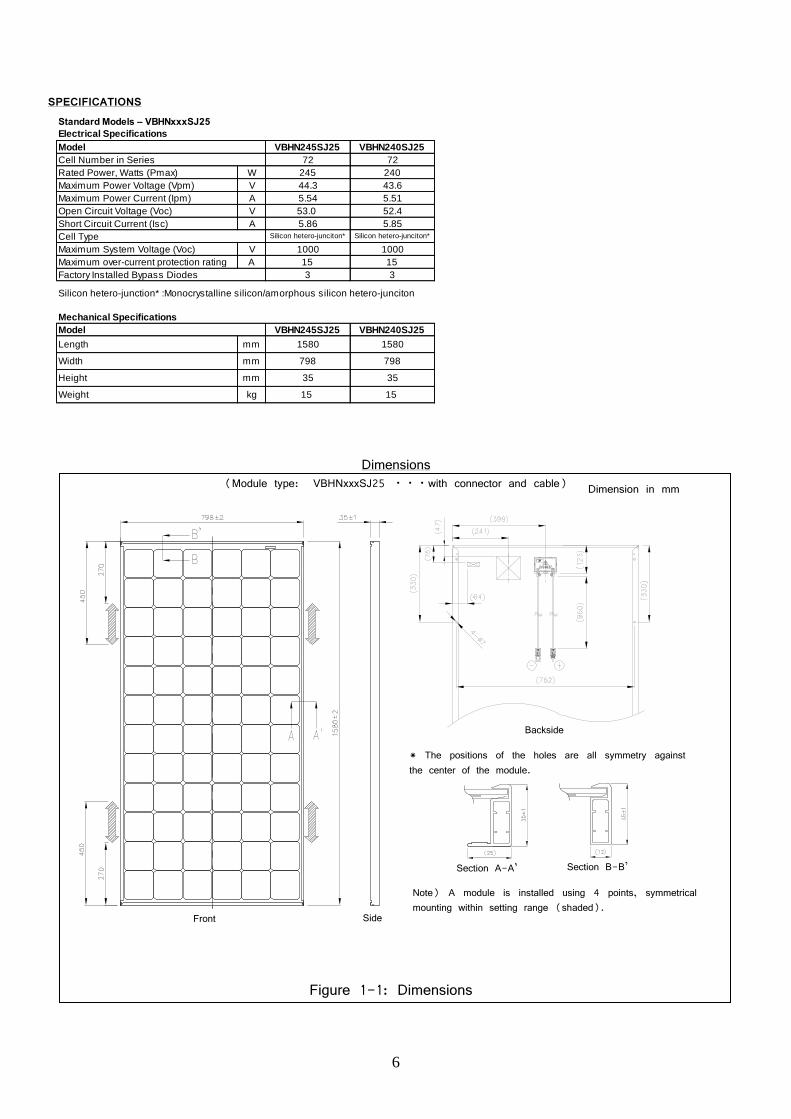
SPECIFICATIONS
Standard Models – VBHNxxxSJ25
Model VBHN245SJ25 VBHN240SJ25
Cell Number in Series 72 72
Rated Power, Watts (Pmax) W 245 240
Maximum Power Voltage (Vpm) V 44.3 43.6
Maximum Power Current (Ipm) A 5.54 5.51
Open Circuit Voltage (Voc) V 53.0 52.4
Short Circuit Current (Isc) A 5.86 5.85
Cell Type Silicon hetero-junciton* Silicon hetero-junciton*
Maximum System Voltage (Voc) V 1000 1000
Maximum over-current protection rating A 15 15
Factory Installed Bypass Diodes 3 3
Silicon hetero-junction* :Monocrystalline silicon/amorphous silicon hetero-junciton
Mechanical Specifications
Model VBHN245SJ25 VBHN240SJ25
Length mm 1580 1580
Width mm 798 798
Height mm 35 35
Weight kg 15 15
Electrical Specifications
Figure 1-1: Dimensions
Dimensions (Module type: VBHNxxxSJ25 ・・・with connector and cable) Dimension in mm
Backside
Side Front
* The positions of the holes are all symmetry against the center of the module.
Note) A module is installed using 4 points, symmetrical mounting within setting range (shaded).
Section A-A’ Section B-B’

7
Solar Module
For questions regarding mounting profiles for modules, Please contact your local dealer.
Module Mounting Structure Rail
M6 Bolt Spring washer
M6 Nut
Flat washer
Figure 2-2 Installation B
Flat washer Spring washer
Installation (reference)
Figure 2-1 Installation A
Solar Module
Metal clamp B (2 places)
Metal clamp A (2 places)
Mounting Structure Rail
1.48” (38mm)
1.48” (38mm) 1.37”
(35mm)
0.43” (11mm)
Dimension in mm Optional Mounting Range A
Figure 1-2: Optional Mounting Range A
Note: Fixing span must not exceed 1040mm.
Dimension in mm
Optional Mounting Range B
Figure 1-3: Optional Mounting Range B
Note: Fixing span must not exceed 1040mm.
Cable
Figure 3: Configuration of Junction Box
Connector (SMK plug)
Positive (+)
Negative (-)

8
SPECIFICATIONS
Standard Models – VBHNxxxSJ40
Model VBHN285SJ40
Cell Number in Series 88
Rated Power, Watts (Pmax) W 285
Maximum Power Voltage (Vpm) V 52.0
Maximum Power Current (Ipm) A 5.49
Open Circuit Voltage (Voc) V 63.5
Short Circuit Current (Isc) A 5.91
Cell Type Silicon hetero-junciton*
Maximum System Voltage (Voc) V 1000
Maximum over-current protection rating A 15
Factory Installed Bypass Diodes 4
Silicon hetero-junciton* :Monocrysttaline silicon/amorphous silicon hetero-junction
Mechanical Specifications
Model VBHN285SJ40
Length mm 1463
Width mm 1053
Height mm 46
Weight kg 18
Electrical Specifications
Figure 5: Dimensions
Dimensions (Module type: VBHNxxxSJ40 ・・・with connector and cable) Dimension in mm
Note) A module is installed using 4 points, symmetrical mounting within setting range (shaded). Fixing span must be between 600-1100mm
* The positions of the holes are all symmetry against the center of the module.
Side Front
Section A-A’ Section B-B’
Backside

9
Solar Module
For questions regarding mounting profiles for modules, Please contact your local dealer.
Module Mounting Structure Rail
M8 Bolt Spring washer
M8 Nut
Flat washer
Figure 6-2 Installation B
Flat washer Spring washer
Installation (reference)
Figure 6-1 Installation A
Solar Module
Metal clamp B (2 places)
Metal clamp A (2 places)
Mounting Structure Rail
1.48” (38mm)
1.48” (38mm) 1.81”
(46mm)
1.34” (34mm)

10
SPECIFICATIONS
Standard Models – VBHNxxxSJ46
Model VBHN285SJ46 VBHN295SJ46
Cell Number in Series 88 88
Rated Power, Watts (Pmax) W 285 295
Maximum Power Voltage (Vpm) V 52.0 52.7
Maximum Power Current (Ipm) A 5.49 5.60
Open Circuit Voltage (Voc) V 63.5 63.7
Short Circuit Current (Isc) A 5.91 6.00
Cell Type Silicon hetero-junciton* Silicon hetero-junciton*
Maximum System Voltage (Voc) V 1000 1000
Maximum over-current protection rating A 15 15
Factory Installed Bypass Diodes 4 4
Silicon hetero-junciton* :Monocrysttaline silicon/amorphous silicon hetero-junction
Mechanical Specifications
Model VBHN285SJ46 VBHN295SJ46
Length mm 1463 1463
Width mm 1053 1053
Height mm 35 35
Weight kg 18 18
Electrical Specifications
Figure 7: Dimensions
Dimensions (Module type: VBHNxxxSJ46 ・・・with connector and cable) Dimension in mm
Note) A module is installed using 4 points, symmetrical mounting within setting range (shaded). Fixing span must be between 836-1200mm
* The positions of the holes are all symmetry against the center of the module.

11
Solar Module
For questions regarding mounting profiles for modules, Please contact your local dealer.
Module Mounting Structure Rail
M8 Bolt Spring washer
M8 Nut
Flat washer
Figure 8-2 Installation B
Flat washer Spring washer
Installation (reference)
Figure 8-1 Installation A
Solar Module
Metal clamp B (2 places)
Metal clamp A (2 places)
Mounting Structure Rail
1.48” (38mm)
1.48” (38mm) 1.37”
(35mm)
0.43” (11mm)

12
SPECIFICATIONS
Standard Models – VBHNxxxSJ47
Model VBHN320SJ47 VBHN325SJ47 VBHN330SJ47
Cell Number in Series 96 96 96
Rated Power, Watts (Pmax) W 320 325 330
Maximum Power Voltage (Vpm) V 57.3 57.6 58.0
Maximum Power Current (Ipm) A 5.59 5.65 5.70
Open Circuit Voltage (Voc) V 69.4 69.6 69.7
Short Circuit Current (Isc) A 5.98 6.03 6.07
Cell Type Silicon hetero-junciton* Silicon hetero-junciton* Silicon hetero-junciton*
Maximum System Voltage (Voc) V 1000 1000 1000
Maximum over-current protection rating A 15 15 15
Factory Installed Bypass Diodes 4 4 4
Silicon hetero-junciton* :Monocrysttaline silicon/amorphous silicon hetero-junction
Mechanical Specifications
Model VBHN320SJ47 VBHN325SJ47 VBHN330SJ47
Length mm 1590 1590 1590
Width mm 1053 1053 1053
Height mm 35 35 35
Weight kg 19 19 19
Electrical Specifications
Figure 9: Dimensions
Dimensions (Module type: VBHNxxxSJ47 ・・・with connector and cable) Dimension in mm
Note) A module is installed using 4 points, symmetrical mounting within setting range (shaded). Fixing span must be between 1030-1230mm
* The positions of the holes are all symmetry against the center of the module.
Backside
Side Front
Section A-A’ Section B-B’

13
Solar Module
For questions regarding mounting profiles for modules, Please contact your local dealer.
Module Mounting Structure Rail
M8 Bolt Spring washer
M8 Nut
Flat washer
Figure 10-2 Installation B
Flat washer Spring washer
Installation (reference)
Figure 10-1 Installation A
Solar Module
Metal clamp B (2 places)
Metal clamp A (2 places)
Mounting Structure Rail
1.48” (38mm)
1.48” (38mm)
1.37” (35mm)
0.43” (11mm)