Embed Size (px)
Citation preview
VB20SL User Guide
Page 1 of 30
VB20SL 20Hz GPS Data Logger
With Slip Angle
User Guide
VB20SL User Guide
Page 2 of 30
Contents CONTENTS .............................................................................................................................................................................................................................................................................................................................. 2
INTRODUCTION .................................................................................................................................................................................................................................................................................................................... 3
FEATURES .............................................................................................................................................................................................................................................................................................................................. 3
STANDARD INVENTORY .................................................................................................................................................................................................................................................................................................... 4
GETTING STARTED ............................................................................................................................................................................................................................................................................................................. 5
ANTENNA TYPES AND PLACEMENT ............................................................................................................................................................................................................................................................................... 7
DISPLAY SCREEN ................................................................................................................................................................................................................................................................................................................. 9
FRONT PANEL CONTROLS .............................................................................................................................................................................................................................................................................................. 10
SLIP ANGLE OFFSET ......................................................................................................................................................................................................................................................................................................... 13
PITCH/ROLL ANGLE OFFSET ......................................................................................................................................................................................................................................................................................... 14
SETTING SLIP ANGLE OFFSET REMOTELY VIA CAN MESSAGES ....................................................................................................................................................................................................................... 14
LEVEL .................................................................................................................................................................................................................................................................................................................................... 15
MEMORY CARDS AND LOGGING .................................................................................................................................................................................................................................................................................. 15
SMOOTHING AND FILTERING ........................................................................................................................................................................................................................................................................................ 16
DIGITAL AND ANALOGUE OUTPUTS ............................................................................................................................................................................................................................................................................ 17
DIGITAL INPUTS ................................................................................................................................................................................................................................................................................................................. 17
CAN / RS232 PORTS / USB .................................................................................................................................................................................................................................................................................................. 18
VB20SL ‘.VBO’ FILE FORMAT ......................................................................................................................................................................................................................................................................................... 21
VBOXTOOLS SOFTWARE ................................................................................................................................................................................................................................................................................................. 22
UPGRADING THE FIRMWARE ........................................................................................................................................................................................................................................................................................ 23
SPECIFICATION .................................................................................................................................................................................................................................................................................................................. 24
CONNECTOR ASSIGNMENTS .......................................................................................................................................................................................................................................................................................... 26
CAN BUS DATA FORMAT .................................................................................................................................................................................................................................................................................................. 28
MODULE DIMENSIONS ..................................................................................................................................................................................................................................................................................................... 29
FUSE RESET BUTTON ........................................................................................................................................................................................................................................................................................................ 29
CONTACT INFORMATION ............................................................................................................................................................................................................................................................................................... 30
VB20SL User Guide
Page 3 of 30
Introduction
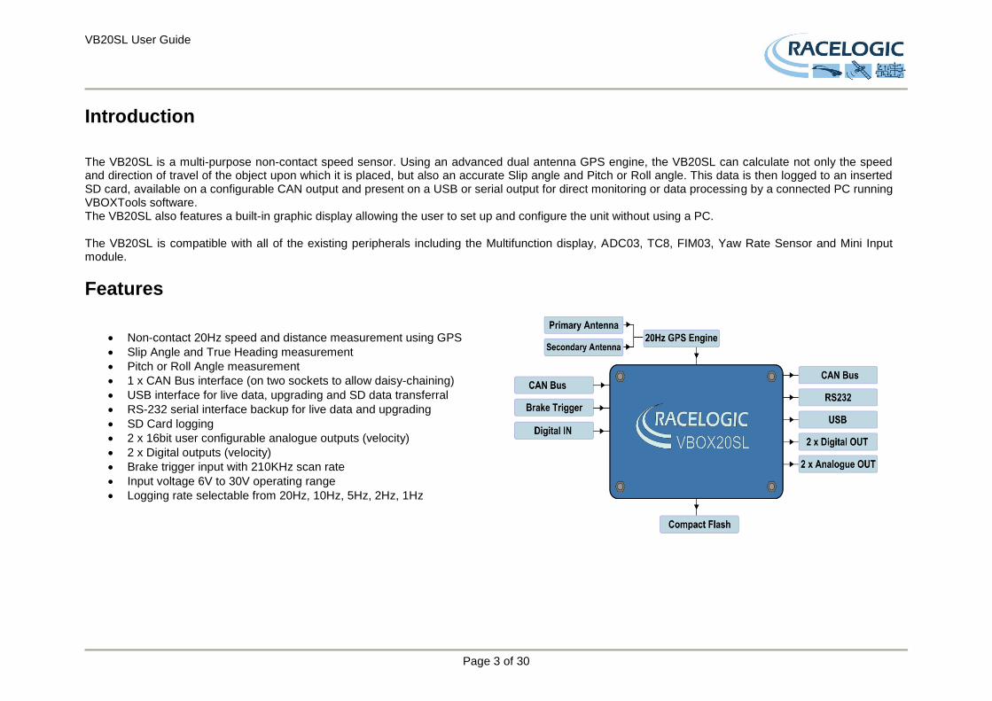
The VB20SL is a multi-purpose non-contact speed sensor. Using an advanced dual antenna GPS engine, the VB20SL can calculate not only the speed and direction of travel of the object upon which it is placed, but also an accurate Slip angle and Pitch or Roll angle. This data is then logged to an inserted SD card, available on a configurable CAN output and present on a USB or serial output for direct monitoring or data processing by a connected PC running VBOXTools software. The VB20SL also features a built-in graphic display allowing the user to set up and configure the unit without using a PC. The VB20SL is compatible with all of the existing peripherals including the Multifunction display, ADC03, TC8, FIM03, Yaw Rate Sensor and Mini Input module.
Features
Non-contact 20Hz speed and distance measurement using GPS
Slip Angle and True Heading measurement
Pitch or Roll Angle measurement
1 x CAN Bus interface (on two sockets to allow daisy-chaining)
USB interface for live data, upgrading and SD data transferral
RS-232 serial interface backup for live data and upgrading
SD Card logging
2 x 16bit user configurable analogue outputs (velocity)
2 x Digital outputs (velocity)
Brake trigger input with 210KHz scan rate
Input voltage 6V to 30V operating range
Logging rate selectable from 20Hz, 10Hz, 5Hz, 2Hz, 1Hz

VB20SL User Guide
Page 4 of 30
Standard Inventory
Description Qty Racelogic Part #
VB20SL-V2 1 VB20SL
Mains Charger (specify UK, EU, US or AU) 1 RLVBACS020
Cigar Lighter Power Cable Adaptor 1 RLCAB10L
USB Lead 1 RLCAB042
2GB SD Card 1 RLACS083
GPS Ground Plane Antenna 2 RLACS103
VBOX Serial PC Cable 1 RLCAB001
CD ROM containing VBOX software 1 RLVBACS030
VBOX Tools Software Manual 1 VBTOOLSMANA5
VBOX 20SL Manual 1 VB20SLMAN
VBOX Carry Case 1 RLVBACS013
VB20SL User Guide
Page 5 of 30
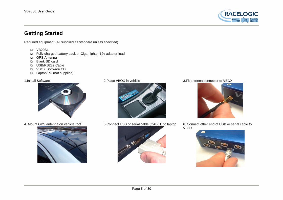
Getting Started Required equipment (All supplied as standard unless specified)
VB20SL Fully charged battery pack or Cigar lighter 12v adapter lead GPS Antenna Blank SD card USB/RS232 Cable VBOX Software CD Laptop/PC (not supplied)
1.Install Software
2.Place VBOX in vehicle
3.Fit antenna connector to VBOX
4. Mount GPS antenna on vehicle roof
5.Connect USB or serial cable (CAB01) to laptop
6. Connect other end of USB or serial cable to VBOX
VB20SL User Guide
Page 6 of 30
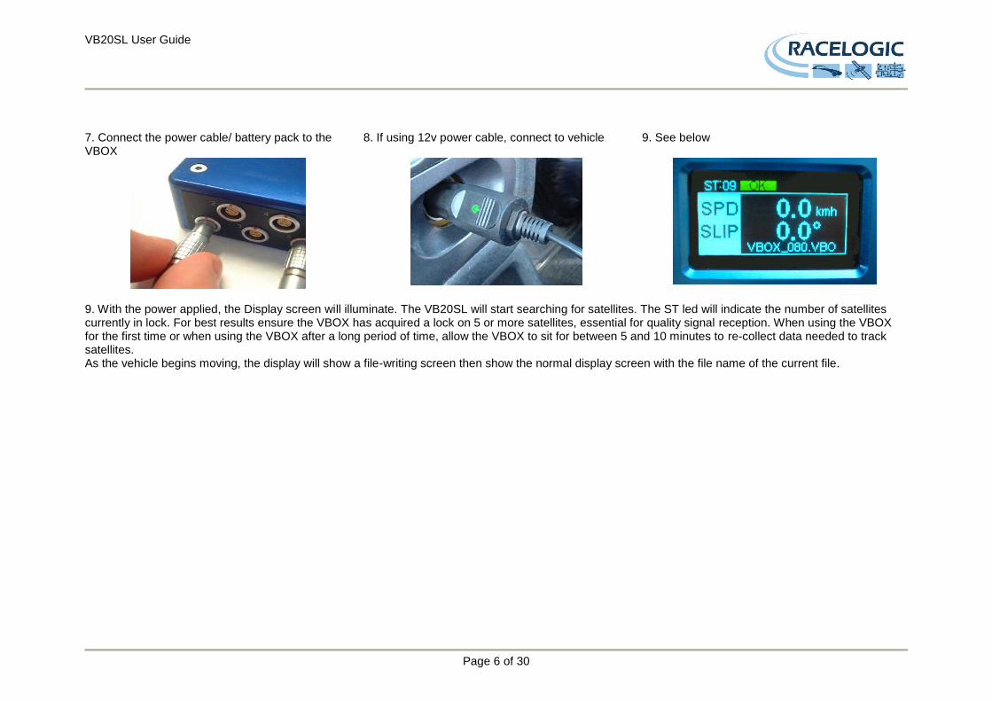
7. Connect the power cable/ battery pack to the VBOX
8. If using 12v power cable, connect to vehicle
9. See below
9. With the power applied, the Display screen will illuminate. The VB20SL will start searching for satellites. The ST led will indicate the number of satellites currently in lock. For best results ensure the VBOX has acquired a lock on 5 or more satellites, essential for quality signal reception. When using the VBOX for the first time or when using the VBOX after a long period of time, allow the VBOX to sit for between 5 and 10 minutes to re-collect data needed to track satellites. As the vehicle begins moving, the display will show a file-writing screen then show the normal display screen with the file name of the current file.
VB20SL User Guide
Page 7 of 30
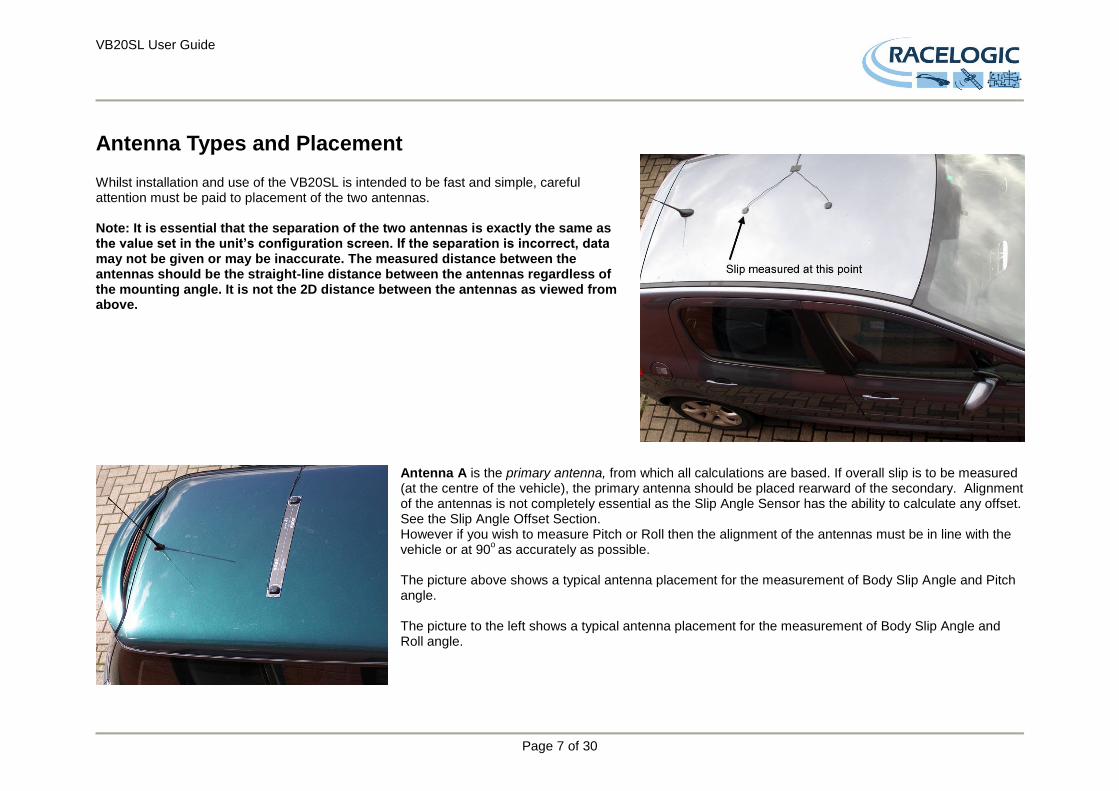
Antenna Types and Placement Whilst installation and use of the VB20SL is intended to be fast and simple, careful attention must be paid to placement of the two antennas. Note: It is essential that the separation of the two antennas is exactly the same as the value set in the unit’s configuration screen. If the separation is incorrect, data may not be given or may be inaccurate. The measured distance between the antennas should be the straight-line distance between the antennas regardless of the mounting angle. It is not the 2D distance between the antennas as viewed from above.
Antenna A is the primary antenna, from which all calculations are based. If overall slip is to be measured (at the centre of the vehicle), the primary antenna should be placed rearward of the secondary. Alignment of the antennas is not completely essential as the Slip Angle Sensor has the ability to calculate any offset. See the Slip Angle Offset Section. However if you wish to measure Pitch or Roll then the alignment of the antennas must be in line with the vehicle or at 90
o as accurately as possible.
The picture above shows a typical antenna placement for the measurement of Body Slip Angle and Pitch angle. The picture to the left shows a typical antenna placement for the measurement of Body Slip Angle and Roll angle.
VB20SL User Guide
Page 8 of 30
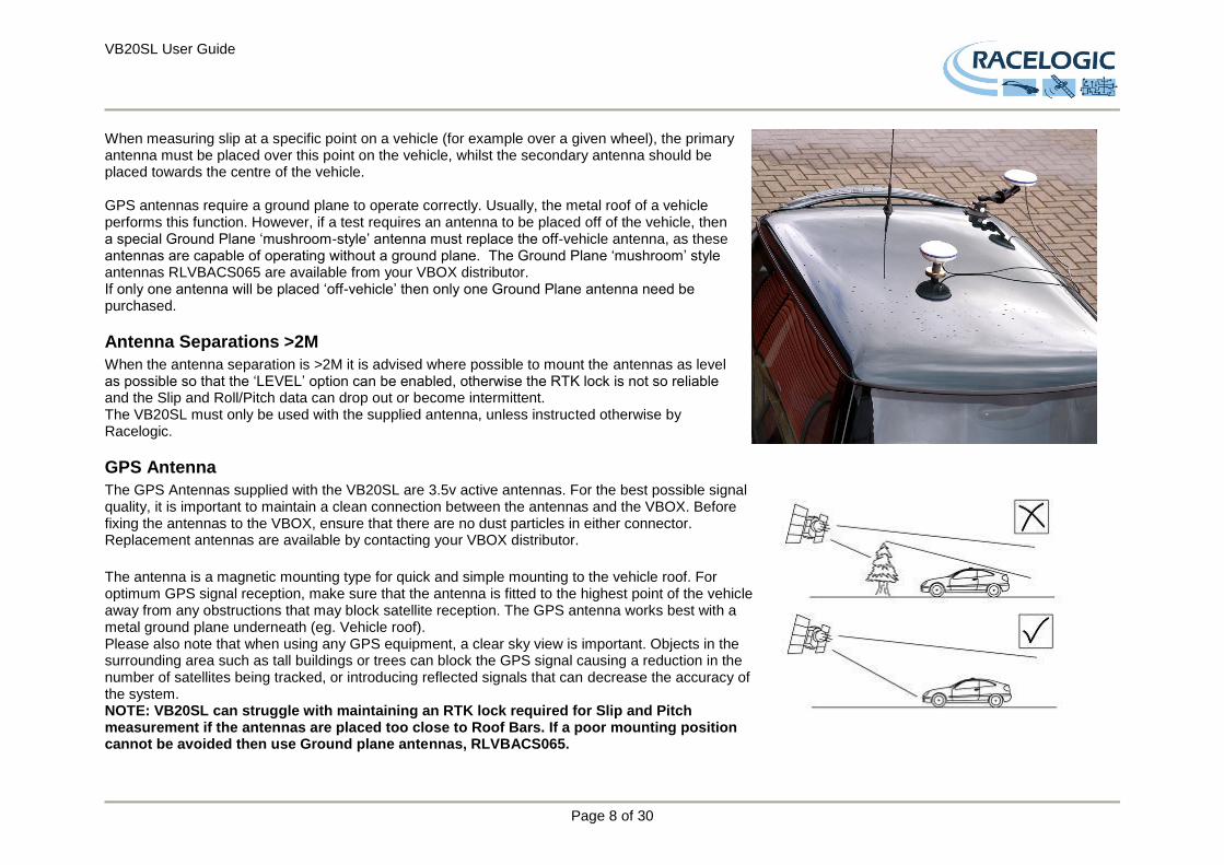
When measuring slip at a specific point on a vehicle (for example over a given wheel), the primary antenna must be placed over this point on the vehicle, whilst the secondary antenna should be placed towards the centre of the vehicle. GPS antennas require a ground plane to operate correctly. Usually, the metal roof of a vehicle performs this function. However, if a test requires an antenna to be placed off of the vehicle, then a special Ground Plane ‘mushroom-style’ antenna must replace the off-vehicle antenna, as these antennas are capable of operating without a ground plane. The Ground Plane ‘mushroom’ style antennas RLVBACS065 are available from your VBOX distributor. If only one antenna will be placed ‘off-vehicle’ then only one Ground Plane antenna need be purchased.
Antenna Separations >2M
When the antenna separation is >2M it is advised where possible to mount the antennas as level as possible so that the ‘LEVEL’ option can be enabled, otherwise the RTK lock is not so reliable and the Slip and Roll/Pitch data can drop out or become intermittent. The VB20SL must only be used with the supplied antenna, unless instructed otherwise by Racelogic.
GPS Antenna
The GPS Antennas supplied with the VB20SL are 3.5v active antennas. For the best possible signal quality, it is important to maintain a clean connection between the antennas and the VBOX. Before fixing the antennas to the VBOX, ensure that there are no dust particles in either connector. Replacement antennas are available by contacting your VBOX distributor.
The antenna is a magnetic mounting type for quick and simple mounting to the vehicle roof. For optimum GPS signal reception, make sure that the antenna is fitted to the highest point of the vehicle away from any obstructions that may block satellite reception. The GPS antenna works best with a metal ground plane underneath (eg. Vehicle roof). Please also note that when using any GPS equipment, a clear sky view is important. Objects in the surrounding area such as tall buildings or trees can block the GPS signal causing a reduction in the number of satellites being tracked, or introducing reflected signals that can decrease the accuracy of the system. NOTE: VB20SL can struggle with maintaining an RTK lock required for Slip and Pitch measurement if the antennas are placed too close to Roof Bars. If a poor mounting position cannot be avoided then use Ground plane antennas, RLVBACS065.
VB20SL User Guide
Page 9 of 30
Using the VB20SL with one GPS antenna
The VB20SL can be used like a traditional VBOX. Only Antenna A is needed if the VB20SL is to be used like a traditional VBOX without the requirement to measure Slip, Pitch, YAW rate and Lateral Acceleration channels. For single antenna use (for standard, non-slip GPS data), the antenna should be connected to the Ant A connector. Velocity can be output on either the Analogue or Digital outputs. The VB20SL has a brake trigger input so not only can the VB20SL measure and output Velocity it can measure and output Trigger Velocity, Trigger to zero Time and Trigger to zero Distance. This data is logged to SD card and available on the CAN bus or USB/serial connection bus along with all the other GPS data.
NOTE: When measuring a braking distance the GPS optimisation must be set to High, via the Front Panel controls. And the Velocity Kalman filter set to 0 (zero).
Display Screen
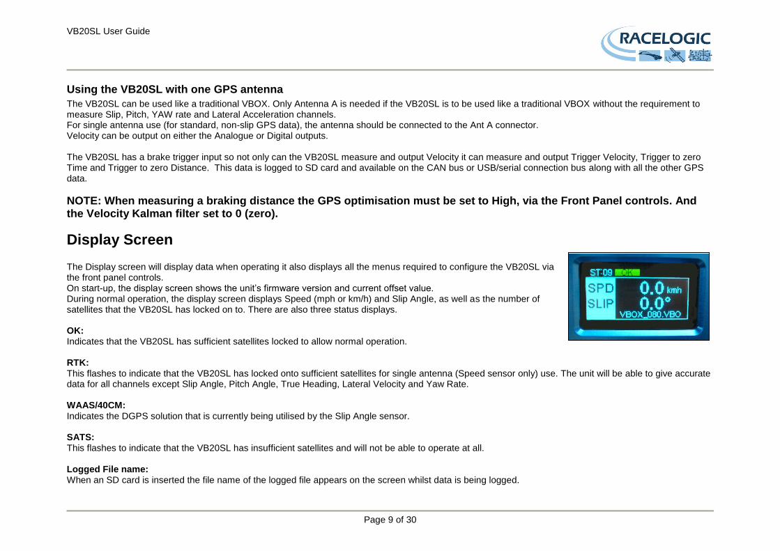
The Display screen will display data when operating it also displays all the menus required to configure the VB20SL via the front panel controls. On start-up, the display screen shows the unit’s firmware version and current offset value. During normal operation, the display screen displays Speed (mph or km/h) and Slip Angle, as well as the number of satellites that the VB20SL has locked on to. There are also three status displays.
OK: Indicates that the VB20SL has sufficient satellites locked to allow normal operation. RTK: This flashes to indicate that the VB20SL has locked onto sufficient satellites for single antenna (Speed sensor only) use. The unit will be able to give accurate data for all channels except Slip Angle, Pitch Angle, True Heading, Lateral Velocity and Yaw Rate. WAAS/40CM: Indicates the DGPS solution that is currently being utilised by the Slip Angle sensor. SATS: This flashes to indicate that the VB20SL has insufficient satellites and will not be able to operate at all. Logged File name: When an SD card is inserted the file name of the logged file appears on the screen whilst data is being logged.
VB20SL User Guide
Page 10 of 30
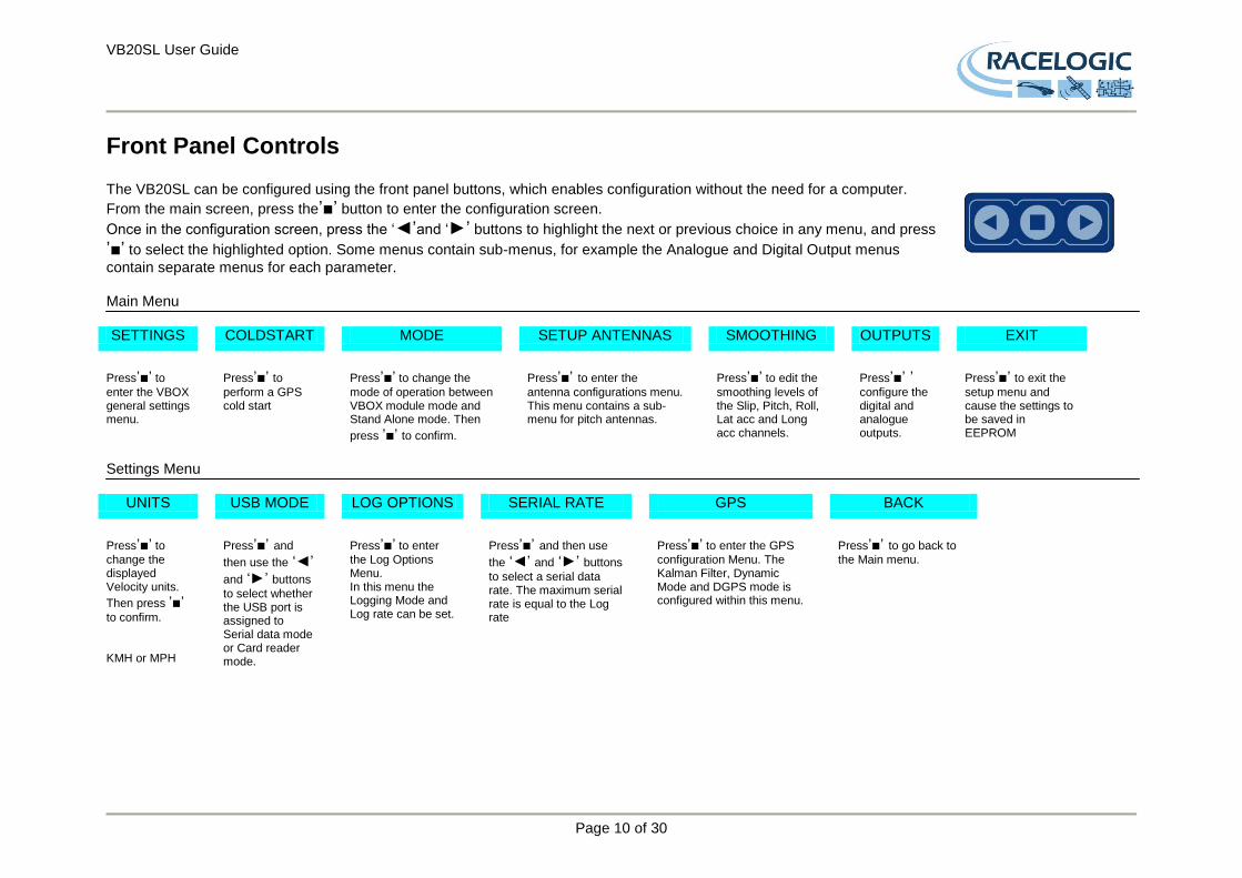
Front Panel Controls The VB20SL can be configured using the front panel buttons, which enables configuration without the need for a computer.
From the main screen, press the’■’ button to enter the configuration screen.
Once in the configuration screen, press the ‘◄’and ‘►’ buttons to highlight the next or previous choice in any menu, and press
’■’ to select the highlighted option. Some menus contain sub-menus, for example the Analogue and Digital Output menus
contain separate menus for each parameter. Main Menu SETTINGS COLDSTART MODE SETUP ANTENNAS SMOOTHING OUTPUTS EXIT
Press’■’ to
enter the VBOX general settings menu.
Press’■’ to
perform a GPS cold start
Press’■’ to change the
mode of operation between VBOX module mode and Stand Alone mode. Then
press ’■’ to confirm.
Press’■’ to enter the
antenna configurations menu. This menu contains a sub-menu for pitch antennas.
Press’■’ to edit the
smoothing levels of the Slip, Pitch, Roll, Lat acc and Long acc channels.
Press’■’ ’ configure the digital and analogue outputs.
Press’■’ to exit the
setup menu and cause the settings to be saved in EEPROM
Settings Menu
UNITS USB MODE LOG OPTIONS SERIAL RATE GPS BACK
Press’■’ to
change the displayed Velocity units.
Then press ’■’ to confirm. KMH or MPH
Press’■’ and
then use the ‘◄’ and ‘►’ buttons
to select whether the USB port is assigned to Serial data mode or Card reader mode.
Press’■’ to enter
the Log Options Menu. In this menu the Logging Mode and Log rate can be set.
Press’■’ and then use
the ‘◄’ and ‘►’ buttons
to select a serial data rate. The maximum serial rate is equal to the Log rate
Press’■’ to enter the GPS
configuration Menu. The Kalman Filter, Dynamic Mode and DGPS mode is configured within this menu.
Press’■’ to go back to
the Main menu.

VB20SL User Guide
Page 11 of 30
Setup Antennas Menu (Pitch Antennas)
SEPARATION LEVEL SWAP ANTENNAS
SLIP OFFSET PITCH OFFSET BACK
Press’■’ and then use the ‘◄’ and ‘►’ buttons to change the
antenna separation. Then press
’■’ to confirm.
Range is 0.0 – 5.0M in 0.1M increments
Press’■’ and then use the ‘◄’ and ‘►’ buttons to enable or disable the
LEVEL option. With the LEVEL set to YES the RTK lock is more resilient. But maximum ROLL or PITCH in this mode should be 10 degrees.
Set to ‘ON’ to allow the primary Antenna A to be mounted ahead of the Secondary Antenna B. Default is ‘OFF’. Then
press ’■’ to confirm.
Press’■’ to enter the
Slip offset sub menu. Within this sub menu the Slip offset can be calculated and applied or cleared.
Press’■’ to enter the
Pitch offset sub menu. Within this sub menu a Pitch offset can be calculated and applied or cleared.
Press’■’ to go
back to the Main menu.
Smoothing Menu
Lat Acc Long Acc Slip Pitch Roll BACK
Press’■’ and then use the ‘◄’ and ‘►’ buttons to
change the amount of smoothing applied to the calculated Lateral Acceleration output. Then
press ’■’ to confirm.
0.0 –5.0 (0.1 steps)
Press’■’ and then use the ‘◄’ and ‘►’ buttons to
change the amount of smoothing applied to the calculated Longitudinal Acceleration output. Then
press ’■’ to confirm.
0.0 –5.0 (0.1 steps)
Press’■’ and then use the ‘◄’ and ‘►’ buttons to
change the amount of smoothing applied to the Slip angle channel. Then
press ’■’ to confirm.
0.0 –5.0 (0.1 steps)
Press’■’ and then use
the ‘◄’ and ‘►’ buttons
to change the amount of smoothing applied to the Pitch angle channel. Then
press ’■’ to confirm.
0.0 –5.0 (0.1 steps)
Press’■’ and then use the ‘◄’ and ‘►’ buttons to
change the amount of smoothing applied to the Roll angle channel. Then
press ’■’ to confirm.
0.0 –5.0 (0.1 steps)
Press’■’ to go back
to the Main menu.
VB20SL User Guide
Page 12 of 30
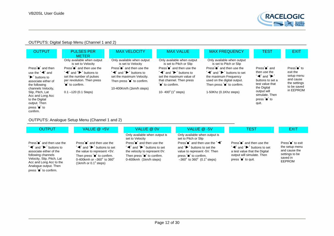
OUTPUTS: Digital Setup Menu (Channel 1 and 2)
OUTPUT PULSES PER METER
MAX VELOCITY MAX VALUE MAX FREQUENCY TEST EXIT
Only available when output is set to Velocity
Only available when output is set to Velocity
Only available when output is set to Pitch or Slip
Only available when output is set to Pitch or Slip
Press’■’ and then
use the ‘◄’ and ‘►’ buttons to
associate either of the following channels Velocity, Slip, Pitch, Lat Acc and Long Acc to the Digital output. Then
press ’■’ to
confirm.
Press’■’ and then use the ‘◄’ and ‘►’ buttons to
set the number of pulses per revolution. Then press
’■’ to confirm.
0.1 –120 (0.1 Steps)
Press’■’ and then use the ‘◄’ and ‘►’ buttons to
set the maximum Velocity.
Then press ’■’ to confirm.
10-400Km/h (1km/h steps)
Press’■’ and then use the ‘◄’ and ‘►’ buttons to
set the maximum value of that channel. Then press
’■’ to confirm.
10- 400
o (1
o steps)
Press’■’ and then use the ‘◄’ and ‘►’ buttons to set
the maximum Frequency used on the digital output.
Then press ’■’ to confirm.
1-50Khz (0.1Khz steps)
Press’■’ and
then use the ‘◄’ and ‘►’ buttons to set a test value that the Digital output will simulate. Then
press ’■’ to
quit.
Press’■’ to
exit the setup menu and cause the settings to be saved in EEPROM
OUTPUTS: Analogue Setup Menu (Channel 1 and 2)
OUTPUT VALUE @ +5V VALUE @ 0V VALUE @ -5V TEST EXIT
Only available when output is set to Velocity
Only available when output is set to Pitch or Slip
Press’■’ and then use the ‘◄’ and ‘►’ buttons to
associate either of the following channels Velocity, Slip, Pitch, Lat Acc and Long Acc to the Analogue output. Then
press ’■’ to confirm.
Press’■’ and then use the ‘◄’ and ‘►’ buttons to set
the value to represent +5V.
Then press ’■’ to confirm.
0-400kmh or –360o to 360
o
(1km/h or 0.1o steps)
Press’■’ and then use the ‘◄’ and ‘►’ buttons to set
the velocity to represent 0V.
Then press ’■’ to confirm.
0-400kmh (1km/h steps)
Press’■’ and then use the ‘◄’ and ‘►’ buttons to set the
value to represent -5V. Then
press ’■’ to confirm.
–360o to 360
o (0.1
o steps)
Press’■’ and then use the ‘◄’ and ‘►’ buttons to set
a test value that the Digital output will simulate. Then
press ’■’ to quit.
Press’■’ to exit
the setup menu and cause the settings to be saved in EEPROM
VB20SL User Guide
Page 13 of 30
Slip Angle Offset When using the VB20SL for measurement of Slip Angle, Pitch / Roll Angle, True Heading, Lateral Velocity or Yaw Rate, it is essential that the Slip Angle offset is determined before conducting tests. This then compensates for any misalignment in the placement of the two antennas. There are also many occasions when the antennas cannot be placed directly in line with the car, such as when an ‘off-vehicle’ antenna is used to measure the Slip angle over a particular wheel. Measuring Roll angle and Slip Angle To measure Roll angle at the same time as slip angle will require the antennas to be mounted at 90 degrees to the body of the car, in this case it is vital that the offset is calculated.
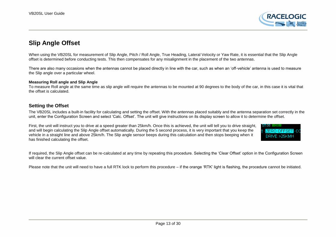
Setting the Offset
The VB20SL includes a built-in facility for calculating and setting the offset. With the antennas placed suitably and the antenna separation set correctly in the unit, enter the Configuration Screen and select ‘Calc. Offset’. The unit will give instructions on its display screen to allow it to determine the offset. First, the unit will instruct you to drive at a speed greater than 25km/h. Once this is achieved, the unit will tell you to drive straight, and will begin calculating the Slip Angle offset automatically. During the 5 second process, it is very important that you keep the vehicle in a straight line and above 25km/h. The Slip angle sensor beeps during this calculation and then stops beeping when it has finished calculating the offset. If required, the Slip Angle offset can be re-calculated at any time by repeating this procedure. Selecting the ‘Clear Offset’ option in the Configuration Screen will clear the current offset value. Please note that the unit will need to have a full RTK lock to perform this procedure – if the orange ‘RTK’ light is flashing, the procedure cannot be initiated.
VB20SL User Guide
Page 14 of 30
Pitch/Roll Angle Offset It is not always possible to mount the antennas on a vehicle so that they are perfectly level. In order to compensate for a non-level antenna placement you should use the Pitch offset facility, which will automatically compute and then use an offset compensation. Measuring Roll angle: To measure Roll angle accurately the antennas need to be aligned as close as possible to a line perpendicular 90
o to the longitudinal line of the car.
Setting the Offset
Press the ’■’ button to enter the Main menu then select the Setup Antenna Menu, and then select the Pitch antenna setup menu. From within either the Pitch antenna setup menu select Pitch Roll offset, when the screen shows ‘CALC OFFSET’ press the ’■’ to calculate the PITCH offset. If required, the Pitch Angle offset can be re-calculated at any time by repeating this procedure. Selecting the ‘Clear Offset’ option will also clear the current offset value.
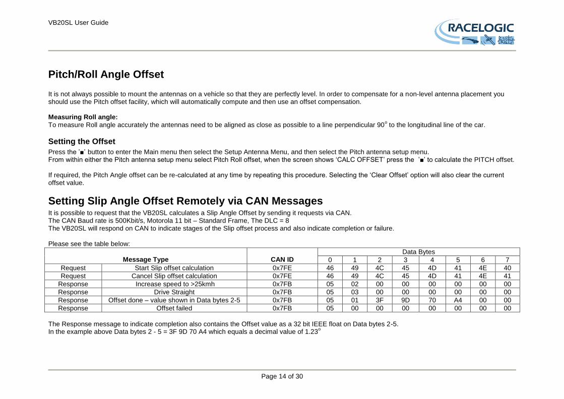
Setting Slip Angle Offset Remotely via CAN Messages It is possible to request that the VB20SL calculates a Slip Angle Offset by sending it requests via CAN. The CAN Baud rate is 500Kbit/s, Motorola 11 bit – Standard Frame, The DLC = 8 The VB20SL will respond on CAN to indicate stages of the Slip offset process and also indicate completion or failure. Please see the table below:
Message Type
CAN ID
Data Bytes
0 1 2 3 4 5 6 7
Request Start Slip offset calculation 0x7FE 46 49 4C 45 4D 41 4E 40
Request Cancel Slip offset calculation 0x7FE 46 49 4C 45 4D 41 4E 41
Response Increase speed to >25kmh 0x7FB 05 02 00 00 00 00 00 00
Response Drive Straight 0x7FB 05 03 00 00 00 00 00 00
Response Offset done – value shown in Data bytes 2-5 0x7FB 05 01 3F 9D 70 A4 00 00
Response Offset failed 0x7FB 05 00 00 00 00 00 00 00
The Response message to indicate completion also contains the Offset value as a 32 bit IEEE float on Data bytes 2-5. In the example above Data bytes 2 - 5 = 3F 9D 70 A4 which equals a decimal value of 1.23
o

VB20SL User Guide
Page 15 of 30
Level The ‘LEVEL’ option should be enabled (set to YES) when the antennas are mounted within 10
o of each other and the expected Pitch/Roll measurement will
not exceed 10o. With the LEVEL option enabled the GPS engines maintains its RTK lock more efficiently and the Slip and Pitch channels are less likely to
drop out. If the expected Pitch or Roll angles will be greater than 10
o then the ‘LEVEL’ option should be disabled (set to ‘NO’).
Note: when the antenna separation is <2M the RTK lock is very resilient in most conditions and scenarios when the ‘Level’ option is not enabled.
Memory Cards and Logging The VB20SL stores logged data onto SD Cards. The supplied SD cards are already optimised for use on the VB20SL and as such do not need formatting before use. Should the SD Card need formatting due to card errors it should only be formatted using the ‘Format Compact Flash’ option in the VBOXTools software. The SD Card will need to be inserted into an SD Card reader (or a VB20SL set to ‘Card Reader’ USB Mode) for this to work. When logging data to an SD Card the OLED display will show the name of the current file at the bottom of the display. It is important not to remove the SD Card while the VB20SL is logging. If the card is removed while the VBOX is writing data to it, there is a risk that the data file may be corrupted resulting in loss of data. If ‘Log only when moving’ is the logging mode selected then wait a short time after the vehicle has stopped for logging to finish and the filename to disappear from the screen. If ‘Log continuously’ is selected, press the Start/stop logging switch if connected or press ’■’ on the front panel. This will enter the on-board configuration screen and close the file so that the card can be removed. It is recommended that files are removed from the disk regularly as writing continuously with out fragments is easy. The more file fragments the harder it is to stream data to the card. There are two Logging modes: ‘Log only when moving’ : In this mode the VBOX will start to log data only when a speed higher than 0.5km/h is detected. ‘Log continuously’: Data is continuously logged to the SD card regardless of vehicle velocity or the number of satellites. To set channels to be logged, they must be selected in the VBOX setup window of VBOXTools, see the VBOXTools manual for further information. Maximum Log channels without Kalman Filter enabled = All standard channels plus 20 input channels Maximum Log channels with Kalman Filter enabled = All standard channels plus 10 input channels
VB20SL User Guide
Page 16 of 30
Smoothing and Filtering Velocity: The VB20Sl has three smoothing settings (Dynamic Modes) for velocity, High Dynamics, Normal and Low Dynamics. High dynamics has the least amount of smoothing and must be used for high dynamic tests where Time or Distance measurements are critical to the test, such as Brake stop and acceleration tests. Slip, Pitch Angle and Acceleration channels: The smoothing routine is set by selecting a value from 0 – 5.0 in 0.1 steps. This value corresponds the size in time (S) of a moving window smoothing routine. e.g. if 0.3 is selected then a smoothing window of 0.3 seconds (6 samples @20Hz) will be applied to the data. Kalman Filter: This filter provides filtering separately to the Velocity and Position channels (long, lat and height). Note with any live filter routine more latency will occur if higher levels of filtering are used. Hence the Kalman filter velocity settings should be set to zero for Brake stops and acceleration runs. It is often better to record un-filtered data then use software filter routines after if necessary as these will have much less impact on latency.
VB20SL User Guide
Page 17 of 30
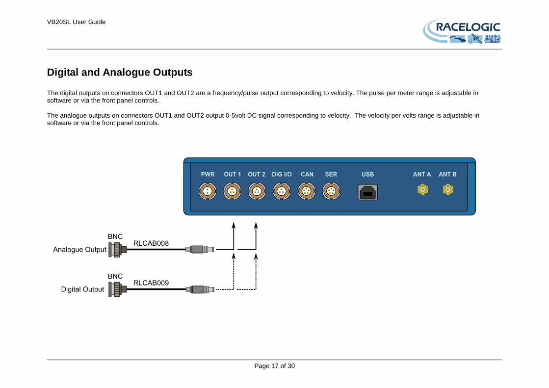
Digital and Analogue Outputs The digital outputs on connectors OUT1 and OUT2 are a frequency/pulse output corresponding to velocity. The pulse per meter range is adjustable in software or via the front panel controls. The analogue outputs on connectors OUT1 and OUT2 output 0-5volt DC signal corresponding to velocity. The velocity per volts range is adjustable in software or via the front panel controls.

VB20SL User Guide
Page 18 of 30
Digital Inputs The DIGITAL I/O socket contains the two digital inputs for the VB20SL. Digital input 1 is also referred to as the Brake trigger input. This input is connected to an internal timer capture module that is able to record precisely an event time for use in brake distance calculation. This period of time is called the trigger event time, and is logged as the value in milliseconds between the trigger event and the last GPS sample. A hand-held brake trigger is also available to allow the user to record marker events in the VB20SL data file. A remote logging on/off switch is also available for ease of use and when the front panel switch is not accessible.
VB20SL User Guide
Page 19 of 30
CAN / RS232 Ports / USB The VB20SL is equipped with a CAN Bus interface, a RS232 serial port and an USB port. The RS232 port or USB is used for all communication between the VBOX and laptop PC. The USB or RS232 ports are able to transmit live data from the VBOX to the PC for viewing and performing real-time tests. Note only the USB port is used for firmware upgrading The CAN Bus port is available in either the socket labelled CAN or the socket labelled Serial. This CAN port has two functions known as Internal and External mode. Internal Mode: This mode should be selected when Racelogic input modules are connected to the VBOX. In this mode the CAN id’s and Baud rate are non configurable. External Mode: This CAN mode should be used when a VBOX CAN data output is to be used by an external CAN device such as a Data acquisition system. In this mode the attributes of the CAN output stream are configurable by the user. See the section ‘Setup’ in the VBOX software manual. The Socket labelled CAN also contains a secondary RS232 port for direct connections to the GPS engine for Local DGPS correction connection.
VB20SL User Guide
Page 20 of 30
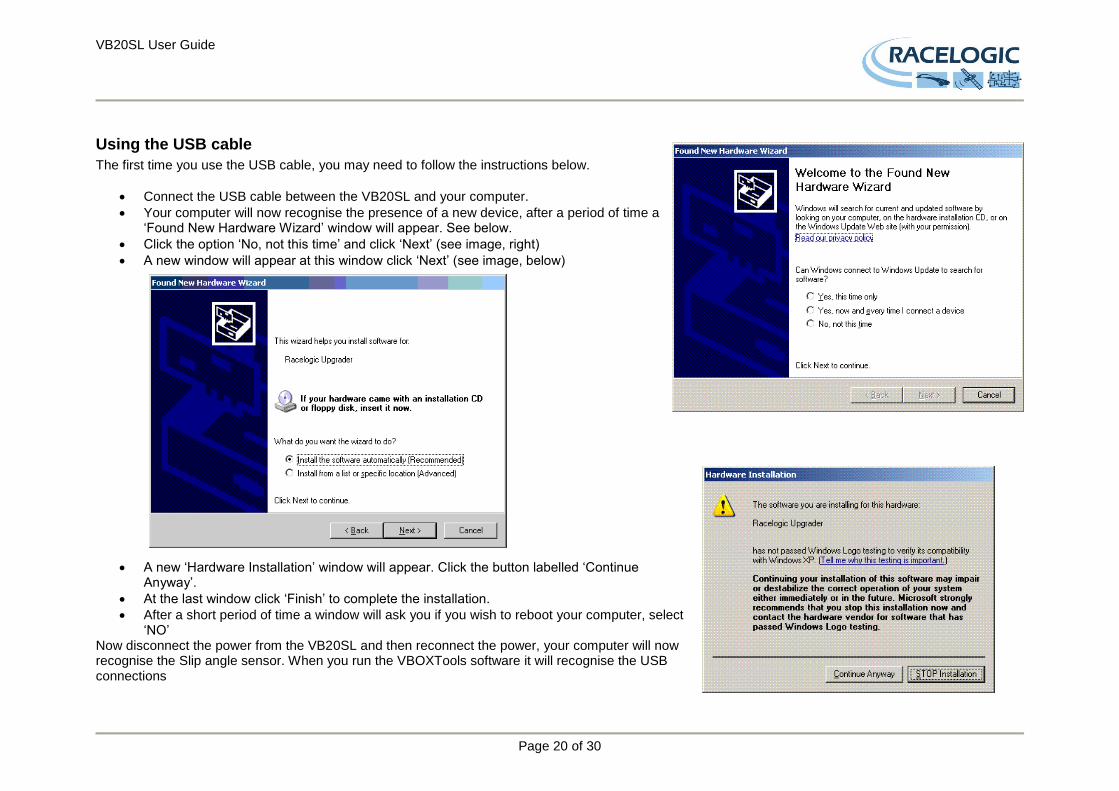
Using the USB cable
The first time you use the USB cable, you may need to follow the instructions below.
Connect the USB cable between the VB20SL and your computer.
Your computer will now recognise the presence of a new device, after a period of time a ‘Found New Hardware Wizard’ window will appear. See below.
Click the option ‘No, not this time’ and click ‘Next’ (see image, right)
A new window will appear at this window click ‘Next’ (see image, below)
A new ‘Hardware Installation’ window will appear. Click the button labelled ‘Continue Anyway’.
At the last window click ‘Finish’ to complete the installation.
After a short period of time a window will ask you if you wish to reboot your computer, select ‘NO’
Now disconnect the power from the VB20SL and then reconnect the power, your computer will now recognise the Slip angle sensor. When you run the VBOXTools software it will recognise the USB connections
VB20SL User Guide
Page 21 of 30
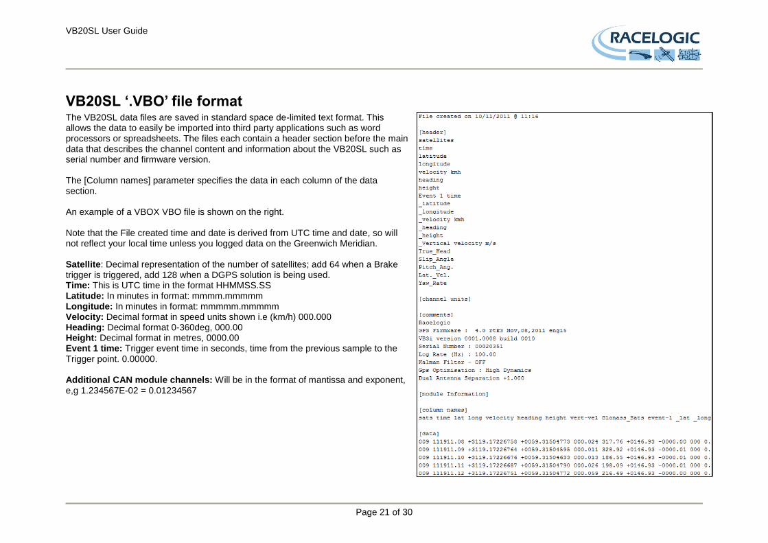
VB20SL ‘.VBO’ file format The VB20SL data files are saved in standard space de-limited text format. This allows the data to easily be imported into third party applications such as word processors or spreadsheets. The files each contain a header section before the main data that describes the channel content and information about the VB20SL such as serial number and firmware version. The [Column names] parameter specifies the data in each column of the data section. An example of a VBOX VBO file is shown on the right. Note that the File created time and date is derived from UTC time and date, so will not reflect your local time unless you logged data on the Greenwich Meridian. Satellite: Decimal representation of the number of satellites; add 64 when a Brake trigger is triggered, add 128 when a DGPS solution is being used. Time: This is UTC time in the format HHMMSS.SS Latitude: In minutes in format: mmmm.mmmmm Longitude: In minutes in format: mmmmm.mmmmm Velocity: Decimal format in speed units shown i.e (km/h) 000.000 Heading: Decimal format 0-360deg, 000.00 Height: Decimal format in metres, 0000.00 Event 1 time: Trigger event time in seconds, time from the previous sample to the Trigger point. 0.00000. Additional CAN module channels: Will be in the format of mantissa and exponent, e,g 1.234567E-02 = 0.01234567
VB20SL User Guide
Page 22 of 30
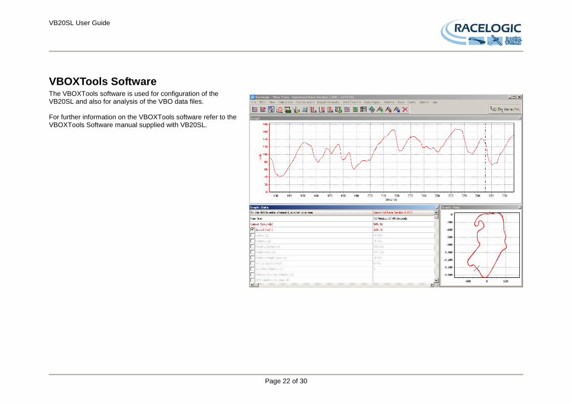
VBOXTools Software The VBOXTools software is used for configuration of the VB20SL and also for analysis of the VBO data files. For further information on the VBOXTools software refer to the VBOXTools Software manual supplied with VB20SL.
VB20SL User Guide
Page 23 of 30
Upgrading the Firmware Occasionally Racelogic releases new versions of firmware code for VBOX products, this maybe to fix bugs or to add new features. New firmware for the VB20SL is loaded into the unit using a computer and the supplied USB cable. The latest firmware upgrade (.ruf) file for the Speed Sensor is available from the VBOX website in the Support section.
http://www.velocitybox.co.uk/index.php/en/support.html If you need the latest file, download it from the website and copy it to your computer. If you are connecting your slip angle sensor to your computer with the USB cable for the first time then follow the instructions in the Section ‘Using the USB cable‘ earlier in this manual before following the instructions below.
How to upgrade the firmware
Press and hold the ‘◄’ button whilst the power is connected to the VBOX2SL.
The screen will now display the UPGRADER screen, showing that it is ready for upgrading
Connect the USB cable to your computer.
Double click on the .ruf firmware upgrade file that you have downloaded from the website
This will automatically run the upgrade program where you will see the progress of the upgrade.
At the end of the process disconnect the USB and then disconnect and reconnect the power. If you have any questions regarding upgrade of VBOX, please do not hesitate to contact [email protected]
VB20SL User Guide
Page 24 of 30
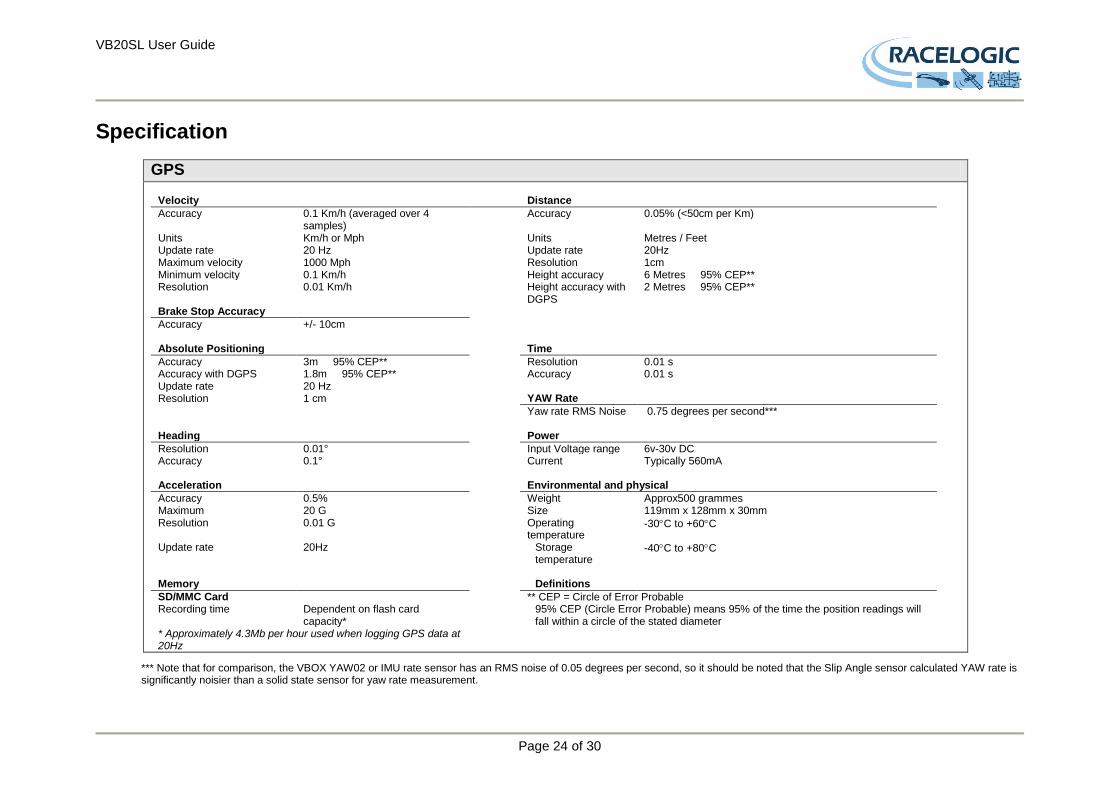
Specification
GPS Velocity Distance
Accuracy 0.1 Km/h (averaged over 4 samples)
Accuracy 0.05% (<50cm per Km)
Units Km/h or Mph Units Metres / Feet Update rate 20 Hz Update rate 20Hz Maximum velocity 1000 Mph Resolution 1cm Minimum velocity 0.1 Km/h Height accuracy 6 Metres 95% CEP** Resolution 0.01 Km/h Height accuracy with
DGPS 2 Metres 95% CEP**
Brake Stop Accuracy
Accuracy +/- 10cm Absolute Positioning Time
Accuracy 3m 95% CEP** Resolution 0.01 s Accuracy with DGPS 1.8m 95% CEP** Accuracy 0.01 s Update rate 20 Hz Resolution 1 cm YAW Rate
Yaw rate RMS Noise 0.75 degrees per second*** Heading Power
Resolution 0.01° Input Voltage range 6v-30v DC Accuracy 0.1° Current Typically 560mA Acceleration Environmental and physical
Accuracy 0.5% Weight Approx500 grammes Maximum 20 G Size 119mm x 128mm x 30mm Resolution 0.01 G Operating
temperature -30C to +60C
Update rate 20Hz Storage temperature
-40C to +80C
Memory Definitions
SD/MMC Card Recording time
Dependent on flash card capacity*
** CEP = Circle of Error Probable 95% CEP (Circle Error Probable) means 95% of the time the position readings will fall within a circle of the stated diameter
* Approximately 4.3Mb per hour used when logging GPS data at 20Hz
*** Note that for comparison, the VBOX YAW02 or IMU rate sensor has an RMS noise of 0.05 degrees per second, so it should be noted that the Slip Angle sensor calculated YAW rate is significantly noisier than a solid state sensor for yaw rate measurement.
VB20SL User Guide
Page 25 of 30
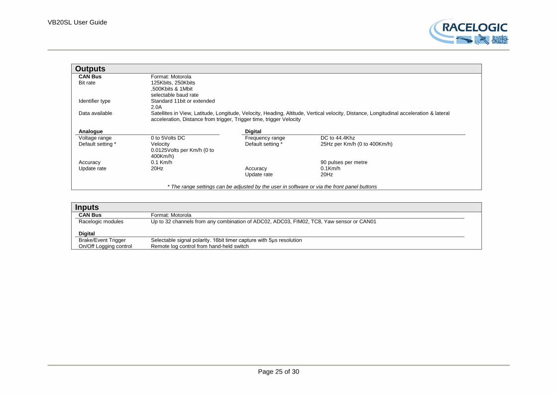
Outputs
CAN Bus Format: Motorola Bit rate 125Kbits, 250Kbits
,500Kbits & 1Mbit selectable baud rate
Identifier type Standard 11bit or extended 2.0A
Data available Satellites in View, Latitude, Longitude, Velocity, Heading, Altitude, Vertical velocity, Distance, Longitudinal acceleration & lateral acceleration, Distance from trigger, Trigger time, trigger Velocity
Analogue Digital
Voltage range 0 to 5Volts DC Frequency range DC to 44.4Khz Default setting * Velocity
0.0125Volts per Km/h (0 to 400Km/h)
Default setting * 25Hz per Km/h (0 to 400Km/h)
Accuracy 0.1 Km/h 90 pulses per metre Update rate 20Hz Accuracy 0.1Km/h Update rate 20Hz
* The range settings can be adjusted by the user in software or via the front panel buttons
Inputs CAN Bus Format: Motorola
Racelogic modules Up to 32 channels from any combination of ADC02, ADC03, FIM02, TC8, Yaw sensor or CAN01 Digital
Brake/Event Trigger Selectable signal polarity. 16bit timer capture with 5μs resolution On/Off Logging control Remote log control from hand-held switch
VB20SL User Guide
Page 26 of 30
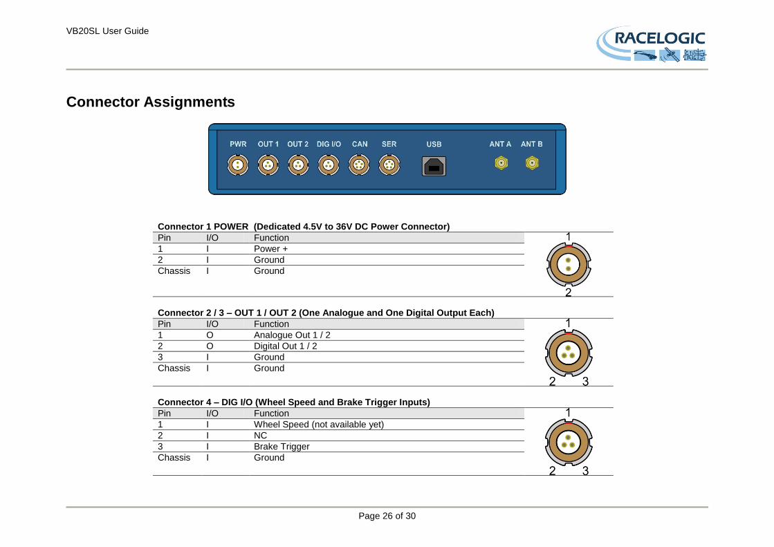
Connector Assignments
Connector 1 POWER (Dedicated 4.5V to 36V DC Power Connector)
Pin I/O Function
1 I Power +
2 I Ground
Chassis I Ground
Connector 2 / 3 – OUT 1 / OUT 2 (One Analogue and One Digital Output Each)
Pin I/O Function
1 O Analogue Out 1 / 2
2 O Digital Out 1 / 2
3 I Ground
Chassis I Ground
Connector 4 – DIG I/O (Wheel Speed and Brake Trigger Inputs)
Pin I/O Function
1 I Wheel Speed (not available yet)
2 I NC
3 I Brake Trigger
Chassis I Ground
VB20SL User Guide
Page 27 of 30
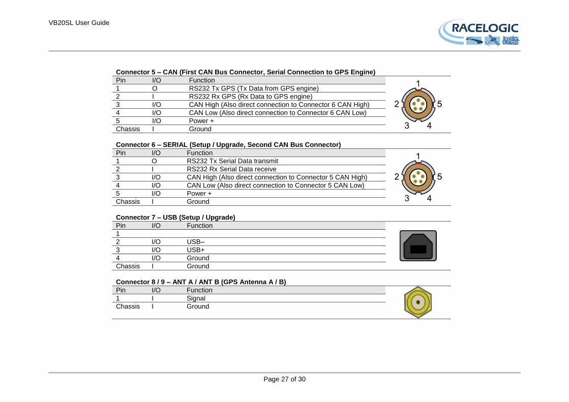
Connector 5 – CAN (First CAN Bus Connector, Serial Connection to GPS Engine)
Pin I/O Function
1 O RS232 Tx GPS (Tx Data from GPS engine)
2 I RS232 Rx GPS (Rx Data to GPS engine)
3 I/O CAN High (Also direct connection to Connector 6 CAN High)
4 I/O CAN Low (Also direct connection to Connector 6 CAN Low)
5 I/O Power +
Chassis I Ground
Connector 6 – SERIAL (Setup / Upgrade, Second CAN Bus Connector)
Pin I/O Function
1 O RS232 Tx Serial Data transmit
2 I RS232 Rx Serial Data receive
3 I/O CAN High (Also direct connection to Connector 5 CAN High)
4 I/O CAN Low (Also direct connection to Connector 5 CAN Low)
5 I/O Power +
Chassis I Ground
Connector 7 – USB (Setup / Upgrade)
Pin I/O Function
1
2 I/O USB–
3 I/O USB+
4 I/O Ground
Chassis I Ground
Connector 8 / 9 – ANT A / ANT B (GPS Antenna A / B)
Pin I/O Function
1 I Signal
Chassis I Ground
VB20SL User Guide
Page 28 of 30
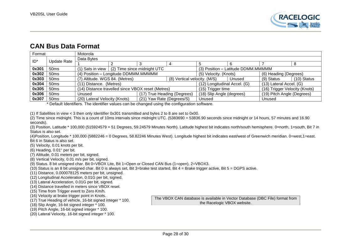
CAN Bus Data Format Format Motorola
ID* Update Rate Data Bytes
1 2 3 4 5 6 7 8
0x301 50ms (1) Sats in view (2) Time since midnight UTC (3) Position – Latitude DDMM.MMMMM
0x302 50ms (4) Position – Longitude DDMMM.MMMMM (5) Velocity. (Knots) (6) Heading (Degrees)
0x303 50ms (7) Altitude. WGS 84. (Metres) (8) Vertical velocity. (M/S) Unused (9) Status (10) Status
0x304 50ms (11) Distance. (Metres) (12) Longitudinal Accel. (G) (13) Lateral Accel. (G)
0x305 50ms (14) Distance travelled since VBOX reset (Metres) (15) Trigger time (16) Trigger Velocity (Knots)
0x306 50ms Unused (17) True Heading (Degrees) (18) Slip Angle (degrees) (19) Pitch Angle (Degrees)
0x307 50ms (20) Lateral Velocity (Knots) (21) Yaw Rate (Degrees/S) Unused Unused
* Default Identifiers. The identifier values can be changed using the configuration software. (1) If Satellites in view < 3 then only Identifier 0x301 transmitted and bytes 2 to 8 are set to 0x00. (2) Time since midnight. This is a count of 10ms intervals since midnight UTC. (5383690 = 53836.90 seconds since midnight or 14 hours, 57 minutes and 16.90 seconds). (3) Position, Latitude * 100,000 (515924579 = 51 Degrees, 59.24579 Minutes North). Latitude highest bit indicates north/south hemisphere. 0=north, 1=south, Bit 7 in Status is also set. (4)Position, Longitude * 100,000 (5882246 = 0 Degrees, 58.82246 Minutes West). Longitude highest bit indicates east/west of Greenwich meridian. 0=west,1=east. Bit 6 in Status is also set. (5) Velocity, 0.01 knots per bit.
(6) Heading, 0.01 per bit. (7) Altitude, 0.01 meters per bit, signed. (8) Vertical Velocity, 0.01 m/s per bit, signed. (9) Status. 8 bit unsigned char. Bit 0=VBOX Lite, Bit 1=Open or Closed CAN Bus (1=open), 2=VBOX3. (10) Status is an 8 bit unsigned char. Bit 0 is always set, Bit 3=brake test started, Bit 4 = Brake trigger active, Bit 5 = DGPS active. (11) Distance, 0.000078125 meters per bit, unsigned. (12) Longitudinal Acceleration, 0.01G per bit, signed. (13) Lateral Acceleration, 0.01G per bit, signed. (14) Distance travelled in meters since VBOX reset. (15) Time from Trigger event to Zero Km/h. (16) Velocity at brake trigger point in Knots. (17) True Heading of vehicle, 16-bit signed integer * 100. (18) Slip Angle, 16-bit signed integer * 100. (19) Pitch Angle, 16-bit signed integer * 100. (20) Lateral Velocity, 16-bit signed integer * 100.
The VBOX CAN database is available in Vector Database (DBC File) format from the Racelogic VBOX website.
VB20SL User Guide
Page 29 of 30
(21) Yaw Rate, 16-bit signed integer * 100.
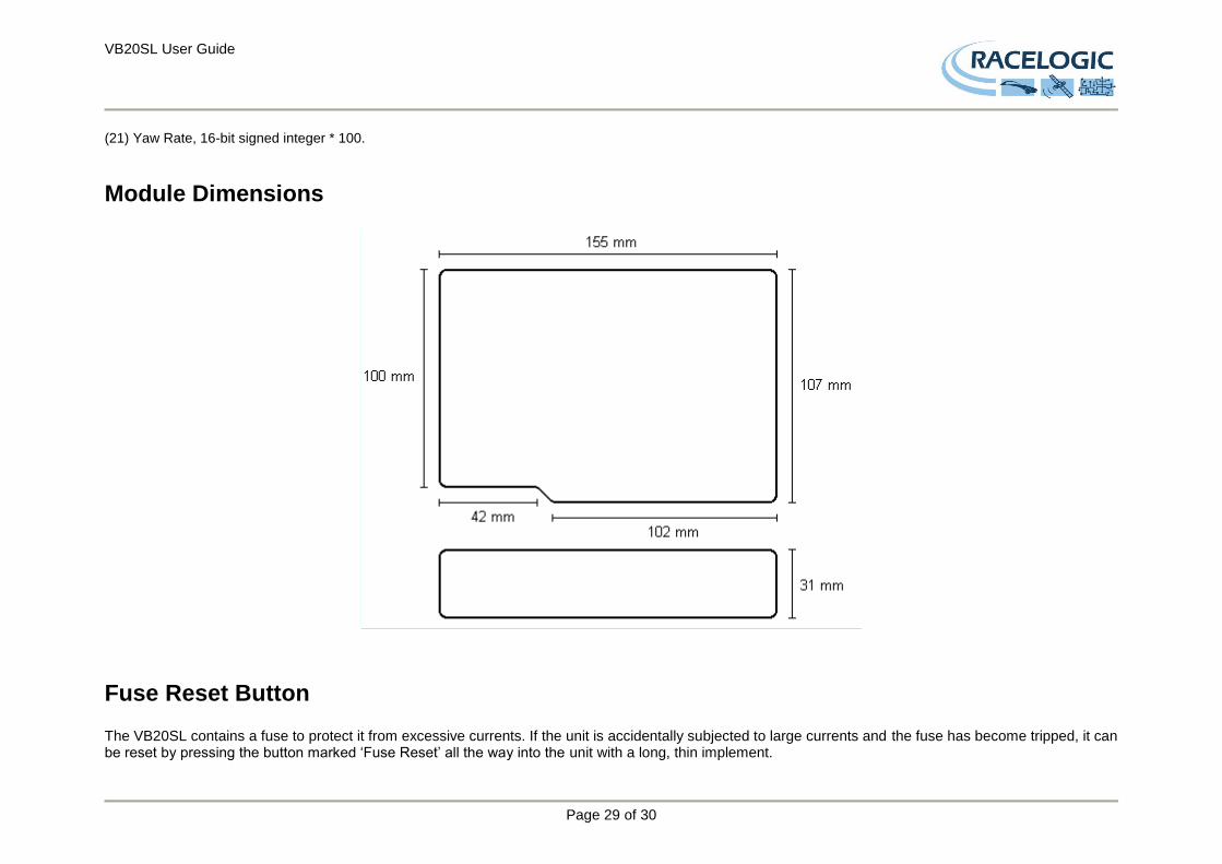
Module Dimensions
Fuse Reset Button The VB20SL contains a fuse to protect it from excessive currents. If the unit is accidentally subjected to large currents and the fuse has become tripped, it can be reset by pressing the button marked ‘Fuse Reset’ all the way into the unit with a long, thin implement.

VB20SL User Guide
Page 30 of 30
Contact Information Racelogic Ltd Unit 10 Swan Business Centre Osier Way Buckingham MK18 1TB UK Tel: +44 (0) 1280 823803 Fax: +44 (0) 1280 823595 Email: [email protected] Web: www.racelogic.co.uk
Revision Date Description Author
1 01/12/06 First release KB
2 11/12/06 Update to CAN format table RK
3 18/12/06 Corrections to power supply voltage requirements JH
4 16/02/07 Addition of YAW rate RMS noise data KB
5 05/06/07 Inclusion of Declaration of Conformity Statement CAS
6 27/06/07 Amendments to manual in accordance to latest firmware v1.01 build 194 KB
7 18/08/07 Correction to Smoothing descriptions KB
8 03/12/07 Addition of Format: Motorola to CAN Bus Data Format table NT
9 30/04/08 Updated Racelogic contact information JH
10 10/01/11 Updated Inventory, Images and general content LN
11 04/04/14 Correction to Antenna setup and DPGS modes RO