Embed Size (px)
Citation preview
© 2019 Schneider Electric. All rights reserved. All trademarks are owned by Schneider Electric Industries SAS or its affiliated companies. September, 2019 tcDocument Number: F-27490-9
www.schneider-electric.com
schneider-electric.com | 1Selection Guide
VB-7000 Series AssembliesSchneider Electric VB-7000 Series 1/2”…2” Globe Valves with NSR Forta M400/800/1500A (VB) and MG350 Series ActuatorsApplicationSchneider Electric NSR Forta M400A-VB, M800A-VB, and M1500A-VB Screw Mount series linear actuators mount directly onto 1/2”…2” VB-7xxx series two-way and three-way globe valve bodies. Schneider Electric NSR Forta M400A, M800A and M1500A U-Bolt series linear actuators mount to a valve with additional linkage. Applications include chilled or hot water and steam. Field selectable input signals include reverse and direct acting, floating or proportional 0…10 Vdc, 2…10 Vdc, or 4…20 mAdc, and proportional sequencing input signal ranges1.
MG350 Non-spring actuators and VB-7000 series two and three-way globe valves provide for control of fan coils, unit ventilators, reheat, cooling units, perimeter heating and other applications. Input signal options include 0…10 Vdc, 2…10 Vdc, 4…20 mA proportional, floating, two-position, and pulse width modulation (PWM).
Note: Do not use for combustible gas applications. The valve packings are not rated for combustible gas applications, and if used in these applications, gas leaks and explosions may result.
Notice:
• Install the valve with the flow in the direction of the flow arrow(s).• Do not exceed the ratings of the device.• Avoid locations where excessive moisture, corrosive fumes or vibration
are present.1) 0-5 Vdc, 5-10 Vdc, 2-6 Vdc, and 6-10 Vdc also available
Forta M400A-VB, M800A-VB, and M1500A-VB Screw Mount MG350
Screw Mount
Table 1. Valve Assembly Part Number Series
Valve Body Part Number Series
Valve Assembly Part Number Series* Type of Valve Inlet Port(s)
Outlet Port(s)
Flow Stem Up
Flow Stem Down
VB-7211 VA,VF,VK,VK4,VS or VU-7211
2-Way Stem Up Open A AB Valve
OpenValve Closed
VB-7212 VA,VF,VK,VK4,VS or VU-7212
VB-7213 VA,VC,VF, VK,VK4,VP,VS or VU-7213
VB-7214 VA,VC,VF, VK,VK4,VP,VS or VU-7214
VB-7253 VA,VC,VF, VK,VK4,VP,VS or VU-7253
VB-7273 VA,VC,VF, VK, VK4,VP,VS or VU-7273
VB-7275 VA,VC,VF, VK,VK4,VP,VS or VU-7275
VB-7221 VA,VF, VK,VK4,VS or VU-7221
2-Way Stem Up Closed A AB Valve
ClosedValve Open
VB-7222 VA,VF,VK,VK4,VS or VU-7222
VB-7223 VA,VF,VK,VK4,VP,VS or VU-7223
VB-7224 VA,VF,VK,VK4,VP,VS or VU-7224
VB-7263 VA,VF,VK,VK4,VP,VS or VU-7263
VB-7283 VA,VF,VK,VK4,VP,VS or VU-7283
VB-7312 VA,VF,VK,VK4,VS or VU-7312
3-Way Mixing B & A AB Flow B to AB
Flow A to ABVB-7313 VA,VC,VF,VK,VK4,VP,VS or VU-7313
VB-7314 VA,VC,VF,VK,VK4,VP,VS or VU-7314
VB-7323 VA,VC,VF,VK,VK4,VP,VS or VU-7323 3-Way Diverting B A & AB Flow B to AB
Flow B to A
VB-7332 VF,VK,VK4,VS or VU-7332 3-Way Se-quencing B & A AB Flow ** B
to ABFlow ** A to AB
* Valve bodies are designated by the prefix VB. When associated with an assembly, the prefix is assigned based on type of actuator. For example, the series part number of a valve assembly with a two-way, normally open, NPT Threaded valve with a pneumatic actuator is VK-7213.** Stem mid stroke no flow both A and B ports are closed
Stem and Bonnet Nut Thread Information for All VB-7000 Valve Series Valve Stem Threads: 1/4”-28 UNF-2A thread Bonnet Nut Threads: 1-1/4” -16 thread Bonnet Nut Outer Hex Size: 1-5/8” (use 1-5/8” open end wrench or equivalent)
Contents1 Table 1. Valve Assembly Part Number Series2 Table 2. Schneider Electric VB-72xx Series
Two-Way Valve Bodies3 Table 3. Schneider Electric VB-73xx Series
Three-Way Valve Bodies4 Table 4. Forta: NSR Actuator Models4 Table 5. MG350V NSR Actuator Models4 Table 6. Forta and MG350 Restrictions on
Ambient Temperature for Valve Actuators5 Table 7. Forta: Select Valve/Actuator Combina-
tion Having Sufficient Close-off for Application5 Table 8. MG350: Select Valve/Actuator Combi-
nation Having Sufficient Close-Off for Applica-tion
5 Table 9. Forta Valve and Actuator Assemblies — Two-Way Valves a
6 Table 10. Forta and MG350 Valve and Actuator Assemblies — Three-Way Mixing Valves a
6 Table 11. Forta Valve and Actuator Assemblies — Diverting Valves a
7 Table 12. Dimensions — Two-Way Valves8 Dimensions — Two-Way Valves for Forta and
MG3509 Table 13. Dimensions — Three-Way Valves

2 | schneider-electric.com Selection Guide
September, 2019 tc © 2019 Schneider Electric. All rights reserved. All trademarks are owned by Schneider Electric Industries SAS or its affiliated companies. Document Number: F-27490-9
Valve Body and Actuator Selection
Table 2. Schneider Electric VB-72xx Series Two-Way Valve Bodies
Two-Way Valves
• Stem Up Open or Stem Up Closed
• 1/2” to 1/1/4” Union• Angle and straightway• 5/8” OD SAE Flared• 1/2” to 2” Union Sweat• 1/2” to 2” NPT or Rp
Threaded
Application: Chilled or Hot Water Application: Hot Water or Steam
Union Angle Union Straightway SAE Flared Union Sweat NPT Threaded
Rp Threaded NPT Threaded
Size 1/2”…1-1/4” 1/2”…1-1/4” 5/8” OD 1/2”…2” 1/2”…2” (15…50 mm) 1/2”…2”
Valve Body Part Number, Stem Up Open VB-7211-0-3-P VB-7211-0-4-P VB-7212-0-4-P VB-7214-0-4-P VB-7213-0-4-P
VB-7215-0-4-Pa VB-7253-0-4-P VB-7273-0-4-P
Valve Body Part Number, Stem Up Closed — VB-7221-0-4-P VB-7222-0-4-P VB-7224-0-4-P VB-7223-0-4-P
VB-7225-0-4-Pa VB-7263-0-4-P VB-7283-0-4-P
Flow Type Equal % Modified Linear
Material
Body Bronze Bronze
Seat Bronze Stainless Steel
Stem Stainless Steel Stainless Steel
Plug Brass Stainless Steel
Packing Spring Loaded TFE/EPDM Spring Loaded TFE
Disc EPDM Teflon None
Pressure Class ANSI 250 Up to 400°F (204°C) below 150°F (65°C) ISO PN16
Maximum Inlet Pressure, Steam 35 PSIG (241 kPa) 100 PSIG
(690 kPa)150 PSIG
(1034 kPa)
Allowable Control Media Temperature 20°F…281 °F (-7°C…138°C) 20…340°F
(-7…171°C)20…400°F(-7…205°C
Allowable Differential Pres-sure, Waterb 35 PSI (241 kPa) for Normal Life 35 PSIG
(241 kPa)35 PSIG
(241 kPa)
Allowable Differential Pres-sure, Steamb 20 PSI (138 kPa) 35 PSI
(241 kPa)50 PSI
(345 kPa)
To Select a Port Code (P)
P Code Valve Size Cv (kvs) Rating
1
1/2”(15 mm)
0.4 (0.34) 0.4 (0.34) 0.4 (0.34) 0.4 (0.34) 0.4 (0.34) 0.4 (0.34) 0.4 (0.34)
2 1.3 (1.1) 1.3 (1.1) 1.3 (1.1) 1.3 (1.1) 1.3 (1.1) 1.3 (1.1) 1.3 (1.1)
3 2.2 (1.9) 2.2 (1.9) 2.2 (1.9) 2.2 (1.9) 2.2 (1.9) 2.2 (1.9) 2.2 (1.9)
4 5.0 (4.3) 4.4 (3.8) 4.4 (3.8) 4.4 (3.8) 4.4 (3.8) 4.4 (3.8) 4.4 (3.8)
53/4” (20 mm)
5.5 (4.7) 5.5 (4.7) — 5.5 (4.7) 5.5 (4.7) 5.5 (4.7) 5.5 (4.7)
6 8.5 (7.4) 7.5 (6.5) — 7.5 (6.5) 7.5 (6.5) 7.5 (6.5) 7.5 (6.5)
71” (25 mm)
14 (12) 10 (8.6) — 10 (8.6) 10 (8.6) 10 (8.6) 10 (8.6)
8 16 (14) 14 (12) — 14 (12) 14 (12) 12 (10.4) 12 (10.4)
9 1-1/4” (32 mm) 22 (19) 20 (17.3) — 20 (17.3) 20 (17.3) 20 (17.3) 20 (17.3)
10 1-1/2” (40 mm) — — — 28 (21.2) 28 (21.2) 28 (21.2) 28 (21.2)
11 2” (50 mm) — — — 40 (34.6) 40 (34.6) 40 (34.6) 40 (34.6)
a - 15…50 mm valves with metric thread Rp 1/2…Rp 2b - Maximum recommended differential in full open position. Do not exceed recommended differential pressure (pressure drop) or integrity of parts may be affected.

schneider-electric.com | 3Selection Guide
© 2019 Schneider Electric. All rights reserved. All trademarks are owned by Schneider Electric Industries SAS or its affiliated companies. September, 2019 tcDocument Number: F-27490-9
Table 3. Schneider Electric VB-73xx Series Three-Way Valve Bodies
Three-Way Valves• Mixing or Diverting• 5/8” OD SAE Flared• 1/2” to 2” NPT or Rp Threaded• 1/2” to 2” Union Sweat
Application: Chilled or Hot Water
SAE Flared NPT Threaded Rp Threaded Union Sweat NPT Threaded
5/8” OD 1/2”…2”(15…50 mm) 1/2”…2” 1/2”…2”
Size
Valve Body Part Number, Mixing a
VB-7312-0-4-P VB-7313-0-4-P VB-7315-0-4-Pb VB-7314-0-4-P —
Valve Body, Part Number Diverting c — — — VB-7323-0-4-P
Material
Flow Type Equal %
Body Bronze
Seat Bronze
Stem Stainless Steel
Plug Brass
Packing Spring Loaded TFE/EPDM
Disc None
Pressure Class ANSI 250 Up to 400°F (204°C) below 150°F (65°C) ISO PN16
Allowable Control Media Temperature
20°F…281°F (-7°C…138°C) 20°F…300°F (-7°C…149°C)
Allowable Differential Pressure, Waterd 35 PSI (241 kPa) for Normal Life
To Select a Port Code (P)
P Code Valve Size Cv (kvs) Rating
0204 1/2” (15 mm)
2.2 (1.9) 2.2 (1.9) 2.2 (1.9) —
4.4 (3.8) 4.4 (3.8) 4.4 (3.8) 4.4 (3.8)
061” (25 mm
— 7.5 (6.5) 7.5 (6.5) 7.5 (6.5)
08 — 14 (12) 14 (12) 15 (13)
09 1-1/4” (32 mm) — 20 (17.3) 20 (17.3 20 (17.3)
10 1-1/2” (40 mm) — 28 (21.2) 28 (21.2) 28 (21.2)
11 2” (50 mm) — 41 (36) 41 (36) 40 (34.6)
a - On VB-7313 and VB-7315 mixing valves, port AB is the common port (located on the side) and ports A and B are inlets. Flow is from B to AB when the valve stem is in up position (port A closed). Flow is from A to AB when valve stem is in down position (port B closed).b - 15 to 50 mm valves with metric thread Rp 1/2 to Rp 2c - On VB-7323 diverting valves, inlet port B is the common port (located on the bottom) and ports AB and B are outlets. When the valve stem is in the up position, flow is from B to AB (port A closed). When the valve stem is in the down position, flow is from port B to A (port AB closed).d - Maximum recommended differential in full open position. Do not exceed recommended differential pressure (pressure drop) or integrity of parts may be affected.

4 | schneider-electric.com Selection Guide
September, 2019 tc © 2019 Schneider Electric. All rights reserved. All trademarks are owned by Schneider Electric Industries SAS or its affiliated companies. Document Number: F-27490-9
Table 4. Forta: NSR Actuator Models
Model Actuator Code
Linkage Kit
Force, lbf (N) Power Running
VATransformer
Sizing VAFloating Controla
Proportional Controla Feedback (2) SPDT Auxiliary
Switches
M400A c — b AV-821c
90(400)
24 Vac ±10%50/60 Hz,
or20 to 29 Vdc
6 30e
Yes
0-10 Vdc,2-10 Vdc,
or4-20 mAdc
with 500 ohm resistor
2-10 Vdc
NoM400A-VB 674 —
M400A-S2 c — b AV-821c
24 Vac 4A resM400A-S2-VB — b —
M800A c — b AV-821c
180(800)
NoM800A-VB 680 —
M800A-S2 c — b AV-821c 15 50e
24 Vac 4A resM800A-S2-VB — b —
M1500A cd — b AV-821c
337(1500)
NoM1500A-VBd 686 —
24 50eM1500A-S2 cd — b AV-821c 24 Vac 4A res
M1500A-S2-VBd — b — 24 Vac 4A res
a - DIP switch selectable.b - No actuator code. No factory assemblies offered.c - AV-821 linkage (order separately) required for mounting actuators to VB-7xxx globe valve bodies using U-Bolt style Forta.d - Do not use M1500 actuators on VB-7323 three way diverting valves.e - M400/800 DC Power 20W, M1500 Dc Power 30W.
Table 5. MG350V NSR Actuator ModelsModel Valve
Assembly Prefix
Actuator Code
Force,lbf (N)
Approx. Timing in Seconds for 1/2” Stroke
Power a Proportional Input b
(VDC)
Proportional Input c
(VDC,mA)
Floating, Two Wire (Form A)
Two Position
PWMd Position OutputSignale
MG350V-24F VF 110 79 (350) 102 5 VA — — Yes — —
MGF350V-24FP VF 112 67 (300) 51 7.2 VA — — Yes Yes2…10 / 0…5 Vdc
MG350V-24M VS 110 79 (350) 102 7.2 VA Yes — — — —
MGF350V-24MP VS 112 67 (300) 51 7.2 VA — Yes — —2…10 / 0…5 Vdc
a - 24 Vac (Class 2 power supply), ±20%, 50/60 Hz, 20…29 Vdc, 5 W; see the MG350V series installation instruction (F-27852) for more information.b - DIP switch configurable 0…10 Vdc or 2…10 Vdc control input, (4…20 mA requires an externally mounted 500 ohm resistor).c - DIP switch configurable 0…10 Vdc, 2…10 Vdc, or 4…20 mA control input.d - DIP switch configurable 0.1…25.5 sec, 0.59…2.93 sec.e - DIP switch configurable 2…10 Vdc or 0…5 Vdc.
Table 6. Forta and MG350 Restrictions on Ambient Temperature for Valve Actuators
Fluid Temperature in Valve Body
Maximum Allowable Ambient Temperaturea
Forta MG350
Chilled Water 122°F (50°C) 131 ˚F (55 ˚C) (Chilled water up to 266 ˚F (130 ˚C) )
281°F (138°C) 113°F (45°C) 127 ˚F (53 ˚C)
300°F (149°C) 107°F (42°C) -
340°F (171°C) 100°F (38°C) 115 ˚F (46 ˚C)
366°F (186°C) 90°F (32°C) -
400 ˚F (204 ˚C) 102 ˚F (39 ˚C) 102 ˚F (39 ˚C)
a - Minimum allowable ambient operating temperature 14°F (-10°C)
NOTE: When installing valve and actuator assemblies, observe the minimum and maximum fluid and ambient temperature limits.
5 | schneider-electric.com Selection Guide
September, 2019 tc © 2019 Schneider Electric. All rights reserved. All trademarks are owned by Schneider Electric Industries SAS or its affiliated companies. Document Number: F-27490-9
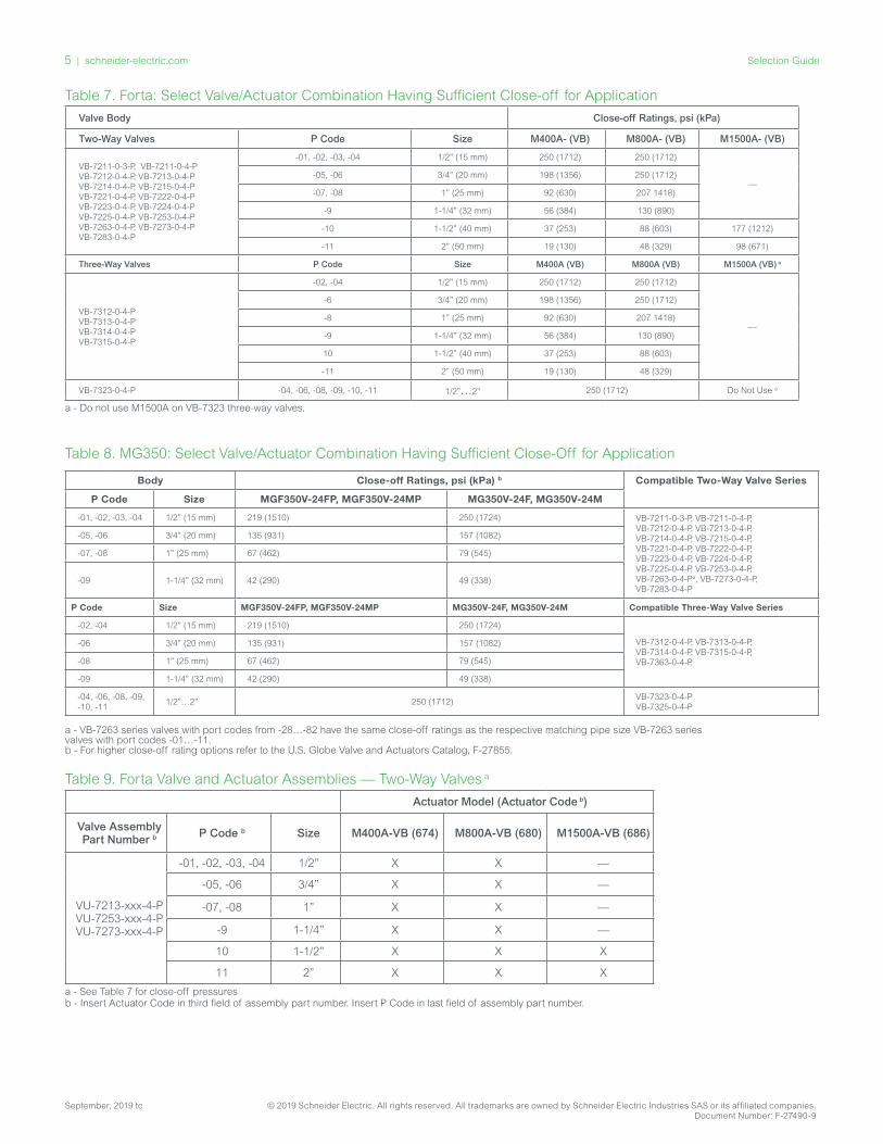
Table 7. Forta: Select Valve/Actuator Combination Having Sufficient Close-off for Application
Valve Body Close-off Ratings, psi (kPa)
Two-Way Valves P Code Size M400A- (VB) M800A- (VB) M1500A- (VB)
VB-7211-0-3-P, VB-7211-0-4-PVB-7212-0-4-P, VB-7213-0-4-PVB-7214-0-4-P, VB-7215-0-4-PVB-7221-0-4-P, VB-7222-0-4-PVB-7223-0-4-P, VB-7224-0-4-PVB-7225-0-4-P, VB-7253-0-4-PVB-7263-0-4-P, VB-7273-0-4-PVB-7283-0-4-P
-01, -02, -03, -04 1/2” (15 mm) 250 (1712) 250 (1712)
—-05, -06 3/4” (20 mm) 198 (1356) 250 (1712)
-07, -08 1” (25 mm) 92 (630) 207 1418)
-9 1-1/4” (32 mm) 56 (384) 130 (890)
-10 1-1/2” (40 mm) 37 (253) 88 (603) 177 (1212)
-11 2” (50 mm) 19 (130) 48 (329) 98 (671)
Three-Way Valves P Code Size M400A (VB) M800A (VB) M1500A (VB) a
VB-7312-0-4-PVB-7313-0-4-PVB-7314-0-4-PVB-7315-0-4-P
-02, -04 1/2” (15 mm) 250 (1712) 250 (1712)
—
-6 3/4” (20 mm) 198 (1356) 250 (1712)
-8 1” (25 mm) 92 (630) 207 1418)
-9 1-1/4” (32 mm) 56 (384) 130 (890)
10 1-1/2” (40 mm) 37 (253) 88 (603)
-11 2” (50 mm) 19 (130) 48 (329)
VB-7323-0-4-P -04, -06, -08, -09, -10, -11 1/2”…2” 250 (1712) Do Not Use a
a - Do not use M1500A on VB-7323 three-way valves.
Table 8. MG350: Select Valve/Actuator Combination Having Sufficient Close-Off for Application
Body Close-off Ratings, psi (kPa) b Compatible Two-Way Valve Series
P Code Size MGF350V-24FP, MGF350V-24MP MG350V-24F, MG350V-24M
-01, -02, -03, -04 1/2” (15 mm) 219 (1510) 250 (1724) VB-7211-0-3-P, VB-7211-0-4-P,VB-7212-0-4-P, VB-7213-0-4-P,VB-7214-0-4-P, VB-7215-0-4-P,VB-7221-0-4-P, VB-7222-0-4-P,VB-7223-0-4-P, VB-7224-0-4-P,VB-7225-0-4-P, VB-7253-0-4-P,VB-7263-0-4-Pa, VB-7273-0-4-P,VB-7283-0-4-P
-05, -06 3/4” (20 mm) 135 (931) 157 (1082)
-07, -08 1” (25 mm) 67 (462) 79 (545)
-09 1-1/4” (32 mm) 42 (290) 49 (338)
P Code Size MGF350V-24FP, MGF350V-24MP MG350V-24F, MG350V-24M Compatible Three-Way Valve Series
-02, -04 1/2” (15 mm) 219 (1510) 250 (1724)
VB-7312-0-4-P, VB-7313-0-4-P,VB-7314-0-4-P, VB-7315-0-4-P,VB-7363-0-4-P,
-06 3/4” (20 mm) 135 (931) 157 (1082)
-08 1” (25 mm) 67 (462) 79 (545)
-09 1-1/4” (32 mm) 42 (290) 49 (338)
-04, -06, -08, -09, -10, -11
1/2”…2” 250 (1712)VB-7323-0-4-P VB-7325-0-4-P
a - VB-7263 series valves with port codes from -28…-82 have the same close-off ratings as the respective matching pipe size VB-7263 series valves with port codes -01…-11. b - For higher close-off rating options refer to the U.S. Globe Valve and Actuators Catalog, F-27855.
Table 9. Forta Valve and Actuator Assemblies — Two-Way Valves a
Actuator Model (Actuator Code b)
Valve Assembly Part Number b P Code b Size M400A-VB (674) M800A-VB (680) M1500A-VB (686)
VU-7213-xxx-4-P VU-7253-xxx-4-P VU-7273-xxx-4-P
-01, -02, -03, -04 1/2” X X —
-05, -06 3/4” X X —
-07, -08 1” X X —
-9 1-1/4” X X —
10 1-1/2” X X X
11 2” X X X
a - See Table 7 for close-off pressuresb - Insert Actuator Code in third field of assembly part number. Insert P Code in last field of assembly part number.

6 | schneider-electric.com Selection Guide
September, 2019 tc © 2019 Schneider Electric. All rights reserved. All trademarks are owned by Schneider Electric Industries SAS or its affiliated companies. Document Number: F-27490-9
Table 10. Forta and MG350 Valve and Actuator Assemblies — Three-Way Mixing Valves a
Valve Assembly Part Number b P Code b Size
Actuator Model (Actuator Code bc)
M400A-VB (674) M800A-VB (680)MGF350V-24FP, MGF350V-24MP (112)
MG350V-24F, MG350V-24M (110)
VU-7313-xxx-4-P
-02, -04 1/2” X X X X
-6 3/4” X X X X
-8 1” X X X X
-9 1-1/4” X X X X
10 1-1/2” X X - -
11 2” X X - -
a - See Table 7 for close-off pressuresb - Insert Actuator Code in third field of assembly part number. Insert P Code in last field of assembly part number. MG350: Enter VF for a floating or two-position or PWM input signal or VS for a proportional (VDC/mA) input signal valve and actuator assembly.c - MG350 Some actuator codes may not be available for all valve assembly part numbers.
Table 11. Forta Valve and Actuator Assemblies — Diverting Valves a
Valve Assembly Part Number b P Code b Size
Actuator Model (Actuator Code )
M400A-VB (674) M800A-VB (680)
VU-7323-674-4-P
-4 1/2” X X
-6 3/4” X X
-8 1” X X
-9 1-1/4” X X
10 1-1/2” X X
11 2” X X
a - See Table 7 for close-off pressuresb - Insert P Code in last field of assembly part number.
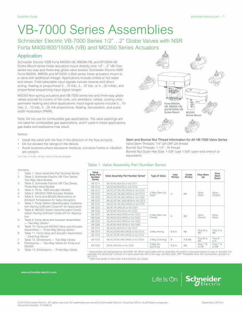
Ø 2.95 in75.0 mm
2.83 in72.0 mm
5.87 in149.0 mm
4.39 in111.5 mm
5.04 in127.9 mm
2.27 in57.7 mm
D
MG350V SmartX Actuator
Dimensions
6.38”(132 mm)
3”(78 mm)
6.31”(173 mm)
9.53”(242 mm)
4.60”(117 mm)
3.235” (82 mm)
D
M400A, M800A, and M1500A U-Bolt Style
M400A-VB, M800A-VB, and M1500A-VB Screw Mount Style
See Table 12
MG350 Dimensions Screw Mount
See Table 12

7 | schneider-electric.com Selection Guide
September, 2019 tc © 2019 Schneider Electric. All rights reserved. All trademarks are owned by Schneider Electric Industries SAS or its affiliated companies. Document Number: F-27490-9
Table 12. Dimensions — Two-Way Valves
Valve Body Part Number Size
Dimensions in Inches (mm)
A B C U-Bolt Stylea-D Screw Mount Stylea-D
MG350 Screw Mount- D
VB-7211-0-3-P
1/2“ 3-1/8 (79) 1-5/8 (41) 3/4 (19) 10-9/32 (261) 7-13/32 (188) 5-7/8 (148)
3/4 “ 3-5/8 (92) 1-11/16 (43) 15/16 (24) 10-15/32 (266) 7-19/32 (193) 6-1/16 (153)
1 “ 4-1/16 (103) 1-15/16 (49) 1-1/4 (32) 10-25/32 (274) 7-29/32 (201) 6-3/8 (161)
1-1/4 “ 4-5/16 (110) 2-3/16 (56) 1-11/16 (43) 11-7/32 (285) 8-11/32 (212) 6-13/16 (172)
VB-7211-0-4-P
1/2 ‘ 4-3/16 (106) 1-1/16 (27) 1-1/8 (29) 10-21/32 (271) 7-25/32 (198) 6-1/4 (158)
3/4“ 4-15/16 (125) 1-1/16 (27) 1-1/8 (29) 10-21/32 (271) 7-25/32 (198) 6-1/4 (158)
1“ 6 (152) 1-1/8 (29) 1-3/16 (30) 10-23/32 (272) 7-27/32 (199) 6-5/16 (166)
1-1/4“ 6-1/4 (159) 1-3/8 (35) 1-7/16 (37) 10-31/32 (279) 8-3/32 (206) 6-9/16 (166)
VB-7212-0-4-P 5/8“ O.D. 4 (102) 1-1/16 (27) 1-1/8 (29) 10-21/32 (271) 7-25/32 (198) 6-14 (158)
VB-7213-0-4-PVB-7215-0-4-PVB-7253-0-4-PVB-7273-0-4-P
1/2” (15 mm) 3 (76) 1-1/16 (27) 1-1/8 (29) 10-21/32 (271) 7-25/32 (198) 6-1/4 (158)
3/4“ (20 mm) 3-5/8 (92) 1-1/16 (27) 1-1/8 (29) 10-21/32 (271) 7-25/32 (198) 6-1/4 (158)
1“ (25 mm) 4-5/8 (117) 1-1/8 (29) 1-3/16 (30) 10-23/32 (272) 7-27/32 (199) 6-5/16 (159)
1-1/4“ (32 mm) 4-5/8 (117) 1-3/8 (35) 1-7/16 (37) 10-31/32 (279) 8-3/32 (206) 6-9/16 (166)
1-1/2 (40 mm) 5-3/8 (137) 1-1/2 (38) 1-7/8 (48) 11-13/32 (290) 8-17/32 (217) 7 (177)
2“(50 mm) 6-1/8 (156) 1-9/16 (40) 2-1/854) 11-21/32 (296) 8-25/32 (223) 7-1/4 (183)
VB-7214-0-4-P
1/2“ 4-3/16 (106) 1-1/16 (27) 1-1/8 (29) 10-21/32 (271) 7-25/32 (198) 6-1/4 (158)
3/4“ 5-7/16 (138) 1-1/16 (27) 1-1/8 (29) 10-21/32 (271) 7-25/32 (198) 6-1/4 (158)
1“ 6-5/8 (168) 1-1/8 (29) 1-3/16 (30) 10-23/32 (272) 7-27/32 (199) 6-5/16 (159)
1-1/4“ 6-13/16 (173) 1-3/8 (35) 1-7/16 (37) 10-31/32 (279) 8-3/32 (206) 6-9/16 (166)
1-1/2“ 8-5/16 (211) 1-1/2 (38) 1-7/8 (48) 11-13/32 (290) 8-17/32 (217) 7 (177)
2“ 9-3/16 (233) 1-9/16 (40) 2-1/854) 11-21/32 (296) 8-25/32 (223) 7-1/4 (183)
VB-7221-0-4-P
1/2” 4-3/16 (106) 1-1/4 (32) 1-1/8 (29) 10-21/32 (271) 7-25/32 (198) 6-1/4 (158)
3/4” 4-15/16 (125) 1-1/4 (32) 1-1/8 (29) 10-21/32 (271) 7-25/32 (198) 6-1/4 (158)
1” 6 (152) 1-3/4 (45) 1-3/16 (30) 10-23/32 (272) 7-27/32 (199) 6-5/16 (159)
1 1/2” 6-1/4 (159) 1-3/4 (45) 1-7/16 (37) 10-31/32 (279) 8-3/32 (206) 6-9/16 (166)
VB-7222-0-4-P 5/8” OD 4 (102) 1-1/4 (32) 1-1/8 (29) 10-21/32 (271) 7-25/32 (198) 6-1/4 (158)
VB-7223-0-4-PVB-7225-0-4-PVB-7263-0-4-PVB-7283-0-4-P
1/2” (15 mm) 3-1/16 (78) 1-3/16 (30) 1-1/8 (29) 10-21/32 (271) 7-25/32 (198) 6-1/4 (158)
3/4“ (20 mm) 3-5/8 (92) 1-3/16 (30) 1-1/8 (29) 10-21/32 (271) 7-25/32 (198) 6-1/4 (158)
1“ (25 mm) 4-5/8 (117) 1-3/4 (44) 1-3/16 (30) 10-23/32 (272) 7-27/32 (199) 6-5/16 (159)
1-1/4“ (32 mm) 4-5/8 (117) 1-3/4 (44) 1-7/16 (37) 10-31/32 (279) 8-3/32 (206) 6-9/16 (166)
1-1/2” (40 mm) 5-3/8 (137) 1-13/16 (46) 1-9/16 (40) 11-3/32(282) 8-7/32 (209) 6-11/16 (169)
2“ (50 mm) 6-1/8 (156) 2-1/4 (57) 1-5/8 (42) 11-5/32 (283) 8-9/32 (210) 6-3/4 (171)
VB-7224-0-4-P
1/2” 4-3/16 (106) 1-1/4 (32) 1-1/8 (29) 10-21/32 (271) 7-25/32 (198) 6-1/4 (158)
3/4” 5-7/16 (138) 1-1/4 (32) 1-1/8 (29) 10-21/32 (271) 7-25/32 (198) 6-1/4 (158)
1” 6-5/8 (168) 1-3/4 (45) 1-3/16 (30) 10-23/32 (272) 7-27/32 (199) 6-5/16 (159)
11/4” 6-13/16 (173) 1-3/4 (45) 1-7/16 (37) 10-31/32 (279) 8-3/32 (206) 6-9/16 (166)
1 1/2” 8-5/16 (211) 1-13/16 (45) 1-9/16 (40) 11-3/32(282) 8-7/32 (209) 6-11/16 (169)
2” 9-3/16 (233) 2-1/16 (53) 1-5/8 (42) 11-5/32 (283) 8-9/32 (210) 6-3/4 (171)
a - Assembly height, centerline of valve body to top of actuator. Leave an additional 3” (76 mm) clearance for cover removal. MG350: Leave an additional 8” (203 mm) clearance for actuator cover removal.

8 | schneider-electric.com Selection Guide
September, 2019 tc © 2019 Schneider Electric. All rights reserved. All trademarks are owned by Schneider Electric Industries SAS or its affiliated companies. Document Number: F-27490-9
Figure 2. Two Way VB-7xxx Valve Body Dimensions
MG350: VB-7251-0-3-P Union Angle
MG350: VB-7211-0-4-P Union Straightway VB-7251-0-4-P Union Straightway
Dimensions — Two and Three-Way Valves for Forta and MG350
(Different valve where noted for MG350)
A
C
B
VB-7313-0-4-P NPT ThreadedVB-7315-0-4-P Rp ThreadedVB-7323-0-4-P NPT Threaded
A
C
B
VB-7314-0-4-P Union SweatVB-7312-0-4-P SAE Flared
A
C
B
Figure 3. Three-Way VB-73xx Valve Body Dimensions
A
B
C
VB-7211-0-3-P Union Angle
A
C
B
VB-7212-0-4-P 5/8” OD SAE Flared
A
C
B
VB-7213-0-4-P NPT ThreadedVB-7215-0-4-P Rp ThreadedVB-7253-0-4-P NPT ThreadedVB-7273-0-4-P NPT Threaded
A
B
C
VB-7211-0-4-P Union Straightway
A
C
B
VB-7214-0-4-P Union Sweat
A
B
C
VB-7221-0-4-P Union Straightway
A
C
B
VB-7222-0-4-P SAE Flared
A
C
B
VB-7223-0-4-P NPT ThreadedVB-7225-0-4-P Rp ThreadedVB-7263-0-4-P NPT ThreadedVB-7283-0-4-P NPT Threaded
A
C
B
VB-7224-0-4-P Union Sweat
schneider-electric.com | 9Selection Guide
© 2019 Schneider Electric. All rights reserved. All trademarks are owned by Schneider Electric Industries SAS or its affiliated companies. September, 2019 tcDocument Number: F-27490-9
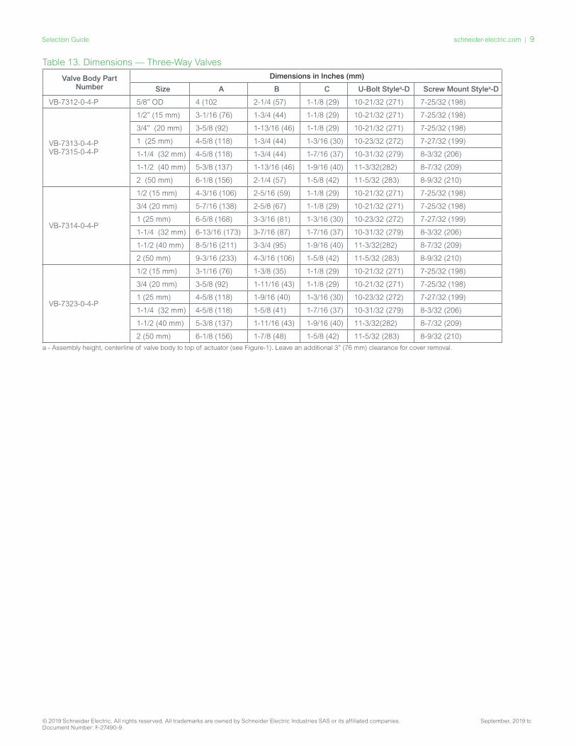
Table 13. Dimensions — Three-Way Valves
Valve Body Part Number
Dimensions in Inches (mm)
Size A B C U-Bolt Stylea-D Screw Mount Stylea-D
VB-7312-0-4-P 5/8” OD 4 (102 2-1/4 (57) 1-1/8 (29) 10-21/32 (271) 7-25/32 (198)
VB-7313-0-4-PVB-7315-0-4-P
1/2” (15 mm) 3-1/16 (76) 1-3/4 (44) 1-1/8 (29) 10-21/32 (271) 7-25/32 (198)
3/4” (20 mm) 3-5/8 (92) 1-13/16 (46) 1-1/8 (29) 10-21/32 (271) 7-25/32 (198)
1 (25 mm) 4-5/8 (118) 1-3/4 (44) 1-3/16 (30) 10-23/32 (272) 7-27/32 (199)
1-1/4 (32 mm) 4-5/8 (118) 1-3/4 (44) 1-7/16 (37) 10-31/32 (279) 8-3/32 (206)
1-1/2 (40 mm) 5-3/8 (137) 1-13/16 (46) 1-9/16 (40) 11-3/32(282) 8-7/32 (209)
2 (50 mm) 6-1/8 (156) 2-1/4 (57) 1-5/8 (42) 11-5/32 (283) 8-9/32 (210)
VB-7314-0-4-P
1/2 (15 mm) 4-3/16 (106) 2-5/16 (59) 1-1/8 (29) 10-21/32 (271) 7-25/32 (198)
3/4 (20 mm) 5-7/16 (138) 2-5/8 (67) 1-1/8 (29) 10-21/32 (271) 7-25/32 (198)
1 (25 mm) 6-5/8 (168) 3-3/16 (81) 1-3/16 (30) 10-23/32 (272) 7-27/32 (199)
1-1/4 (32 mm) 6-13/16 (173) 3-7/16 (87) 1-7/16 (37) 10-31/32 (279) 8-3/32 (206)
1-1/2 (40 mm) 8-5/16 (211) 3-3/4 (95) 1-9/16 (40) 11-3/32(282) 8-7/32 (209)
2 (50 mm) 9-3/16 (233) 4-3/16 (106) 1-5/8 (42) 11-5/32 (283) 8-9/32 (210)
VB-7323-0-4-P
1/2 (15 mm) 3-1/16 (76) 1-3/8 (35) 1-1/8 (29) 10-21/32 (271) 7-25/32 (198)
3/4 (20 mm) 3-5/8 (92) 1-11/16 (43) 1-1/8 (29) 10-21/32 (271) 7-25/32 (198)
1 (25 mm) 4-5/8 (118) 1-9/16 (40) 1-3/16 (30) 10-23/32 (272) 7-27/32 (199)
1-1/4 (32 mm) 4-5/8 (118) 1-5/8 (41) 1-7/16 (37) 10-31/32 (279) 8-3/32 (206)
1-1/2 (40 mm) 5-3/8 (137) 1-11/16 (43) 1-9/16 (40) 11-3/32(282) 8-7/32 (209)
2 (50 mm) 6-1/8 (156) 1-7/8 (48) 1-5/8 (42) 11-5/32 (283) 8-9/32 (210)
a - Assembly height, centerline of valve body to top of actuator (see Figure-1). Leave an additional 3” (76 mm) clearance for cover removal.

10 | schneider-electric.com Selection Guide
September, 2019 tc © 2019 Schneider Electric. All rights reserved. All trademarks are owned by Schneider Electric Industries SAS or its affiliated companies. Document Number: F-27490-9