Embed Size (px)
Citation preview
VAXstation 4000 VLCService InformationOrder Number: EK-V48VB-SV.001

<set_trademark_table>(no_list)
ii
November 1991<set_fcc_warning>(a)
© Digital Equipment Corporation 1990.
All Rights Reserved.
The following are trademarks of Digital Equipment Corporation: DEC, Digital, theDIGITAL logo, Ethernet, ThinWire, VAX, VAXstation, and VMS.
This document was prepared using VAX DOCUMENT, Version 2.0.
Contents
Preface . . . . . . . . . . . . . . . . . . . . . . . . . . . . . . . . . . . . . . . . . . . . . . . . . . . . . xi
1 VAXstation 4000 VLC System Components
1.1 Overview . . . . . . . . . . . . . . . . . . . . . . . . . . . . . . . . . . . . . . . . . . . 1–11.2 Central Processor Unit . . . . . . . . . . . . . . . . . . . . . . . . . . . . . . . . . 1–61.2.1 Processor Restart . . . . . . . . . . . . . . . . . . . . . . . . . . . . . . . . . . 1–81.2.2 Interrupt Controller . . . . . . . . . . . . . . . . . . . . . . . . . . . . . . . . 1–91.2.3 Interrupt Sources and Ranking . . . . . . . . . . . . . . . . . . . . . . . 1–101.2.4 Interrupt Vector Generation . . . . . . . . . . . . . . . . . . . . . . . . . . 1–101.3 Main Memory . . . . . . . . . . . . . . . . . . . . . . . . . . . . . . . . . . . . . . . . 1–111.3.1 Main Memory Requests . . . . . . . . . . . . . . . . . . . . . . . . . . . . . 1–121.3.2 DMA Mapping . . . . . . . . . . . . . . . . . . . . . . . . . . . . . . . . . . . . 1–131.3.3 Translation . . . . . . . . . . . . . . . . . . . . . . . . . . . . . . . . . . . . . . . 1–131.4 ROM Memory . . . . . . . . . . . . . . . . . . . . . . . . . . . . . . . . . . . . . . . . 1–141.4.1 System ROM . . . . . . . . . . . . . . . . . . . . . . . . . . . . . . . . . . . . . 1–141.4.2 Network Address ROM . . . . . . . . . . . . . . . . . . . . . . . . . . . . . 1–141.5 Graphics Controller . . . . . . . . . . . . . . . . . . . . . . . . . . . . . . . . . . . 1–151.5.1 Graphics Controller Screen Formats . . . . . . . . . . . . . . . . . . . 1–161.5.2 Graphics Controller Communication . . . . . . . . . . . . . . . . . . . 1–161.6 Serial Line Controller Feature . . . . . . . . . . . . . . . . . . . . . . . . . . . 1–171.6.1 Serial Line Controller Registers . . . . . . . . . . . . . . . . . . . . . . . 1–171.7 Time-of-Year Clock . . . . . . . . . . . . . . . . . . . . . . . . . . . . . . . . . . . . 1–181.7.1 Battery Backup . . . . . . . . . . . . . . . . . . . . . . . . . . . . . . . . . . . 1–181.7.2 TOY Clock Chip Register . . . . . . . . . . . . . . . . . . . . . . . . . . . . 1–181.8 Network Controller Feature . . . . . . . . . . . . . . . . . . . . . . . . . . . . . 1–201.8.1 Packet Format . . . . . . . . . . . . . . . . . . . . . . . . . . . . . . . . . . . . 1–201.8.2 Network Addresses . . . . . . . . . . . . . . . . . . . . . . . . . . . . . . . . 1–211.9 SCSI Controller Feature . . . . . . . . . . . . . . . . . . . . . . . . . . . . . . . 1–211.9.1 SCSI Bus Signals . . . . . . . . . . . . . . . . . . . . . . . . . . . . . . . . . . 1–22
iii
2 VAXstation 4000 VLC System Configuration
2.1 VAXstation 4000 VLC System Box . . . . . . . . . . . . . . . . . . . . . . . . 2–12.1.1 Mass Storage Device . . . . . . . . . . . . . . . . . . . . . . . . . . . . . . . 2–32.1.2 Power Supply . . . . . . . . . . . . . . . . . . . . . . . . . . . . . . . . . . . . . 2–32.1.2.1 Power Supply Specifications . . . . . . . . . . . . . . . . . . . . . . . 2–42.1.3 VAXstation 4000 VLC System Controls . . . . . . . . . . . . . . . . . 2–62.1.4 System Box Internal Cabling . . . . . . . . . . . . . . . . . . . . . . . . . 2–72.1.5 VAXstation 4000 VLC I/O Panel . . . . . . . . . . . . . . . . . . . . . . 2–72.1.6 VAXstation 4000 VLC System Box Specifications . . . . . . . . . . 2–8
3 VAXstation 4000 VLC Firmware
3.1 Power-Up Initialization Code . . . . . . . . . . . . . . . . . . . . . . . . . . . . 3–23.2 Console Overview . . . . . . . . . . . . . . . . . . . . . . . . . . . . . . . . . . . . . 3–33.3 Extended Self Test Overview . . . . . . . . . . . . . . . . . . . . . . . . . . . . 3–43.4 Utilities Overview . . . . . . . . . . . . . . . . . . . . . . . . . . . . . . . . . . . . 3–53.5 System ROM Overview . . . . . . . . . . . . . . . . . . . . . . . . . . . . . . . . 3–63.5.1 System ROM Part Format . . . . . . . . . . . . . . . . . . . . . . . . . . . 3–63.5.2 System ROM Set Format . . . . . . . . . . . . . . . . . . . . . . . . . . . . 3–73.6 Configuration Table Overview . . . . . . . . . . . . . . . . . . . . . . . . . . . 3–93.6.1 Main Configuration Table . . . . . . . . . . . . . . . . . . . . . . . . . . . 3–103.6.2 Device Configuration Table . . . . . . . . . . . . . . . . . . . . . . . . . . 3–113.7 Driver Descriptor . . . . . . . . . . . . . . . . . . . . . . . . . . . . . . . . . . . . . 3–153.8 Interfacing to Diagnostic Drivers . . . . . . . . . . . . . . . . . . . . . . . . . 3–173.9 Console Driver Interface . . . . . . . . . . . . . . . . . . . . . . . . . . . . . . . 3–193.9.1 Shared Console Interface Area . . . . . . . . . . . . . . . . . . . . . . . . 3–203.9.2 Console Port Driver . . . . . . . . . . . . . . . . . . . . . . . . . . . . . . . . 3–22
4 Diagnostic Testing
4.1 Diagnostic Testing . . . . . . . . . . . . . . . . . . . . . . . . . . . . . . . . . . . . 4–14.1.1 Power-Up Test . . . . . . . . . . . . . . . . . . . . . . . . . . . . . . . . . . . . 4–24.1.2 Displaying System Configuration . . . . . . . . . . . . . . . . . . . . . . 4–44.1.3 Displaying System Errors . . . . . . . . . . . . . . . . . . . . . . . . . . . 4–64.2 Running the Self Test . . . . . . . . . . . . . . . . . . . . . . . . . . . . . . . . . 4–74.2.0.1 TOY/NVR Self Test . . . . . . . . . . . . . . . . . . . . . . . . . . . . . 4–84.2.0.2 LCG Self Tests . . . . . . . . . . . . . . . . . . . . . . . . . . . . . . . . . 4–94.2.0.3 DZ Self Test . . . . . . . . . . . . . . . . . . . . . . . . . . . . . . . . . . . 4–104.2.0.4 Cache Self Test . . . . . . . . . . . . . . . . . . . . . . . . . . . . . . . . 4–114.2.0.5 System Self Test . . . . . . . . . . . . . . . . . . . . . . . . . . . . . . . . 4–114.2.0.6 Floating Point Unit Self Test . . . . . . . . . . . . . . . . . . . . . . 4–114.2.0.7 Interval Timer Self Test . . . . . . . . . . . . . . . . . . . . . . . . . . 4–12
iv
4.2.0.8 Memory Self Test . . . . . . . . . . . . . . . . . . . . . . . . . . . . . . . 4–124.2.0.9 Network Interconnect Self Test . . . . . . . . . . . . . . . . . . . . 4–134.2.0.10 SCSI Self Test . . . . . . . . . . . . . . . . . . . . . . . . . . . . . . . . . 4–144.2.0.11 Audio Self Test . . . . . . . . . . . . . . . . . . . . . . . . . . . . . . . . . 4–144.3 Utilities . . . . . . . . . . . . . . . . . . . . . . . . . . . . . . . . . . . . . . . . . . . . 4–154.4 System Console . . . . . . . . . . . . . . . . . . . . . . . . . . . . . . . . . . . . . . 4–174.4.1 SET and SHOW Commands . . . . . . . . . . . . . . . . . . . . . . . . . . 4–184.4.1.1 SET and SHOW Command Syntax . . . . . . . . . . . . . . . . . 4–194.4.2 SET and SHOW Parameters . . . . . . . . . . . . . . . . . . . . . . . . . 4–194.4.2.1 BFLG . . . . . . . . . . . . . . . . . . . . . . . . . . . . . . . . . . . . . . . . 4–194.4.2.2 BOOT . . . . . . . . . . . . . . . . . . . . . . . . . . . . . . . . . . . . . . . . 4–204.4.2.3 CONFIG . . . . . . . . . . . . . . . . . . . . . . . . . . . . . . . . . . . . . . 4–204.4.2.4 DEVICE . . . . . . . . . . . . . . . . . . . . . . . . . . . . . . . . . . . . . . 4–214.4.2.5 DIAGENV . . . . . . . . . . . . . . . . . . . . . . . . . . . . . . . . . . . . 4–224.4.2.6 ERROR . . . . . . . . . . . . . . . . . . . . . . . . . . . . . . . . . . . . . . 4–234.4.2.7 ETHER . . . . . . . . . . . . . . . . . . . . . . . . . . . . . . . . . . . . . . 4–234.4.2.8 FBOOT . . . . . . . . . . . . . . . . . . . . . . . . . . . . . . . . . . . . . . 4–244.4.2.9 HALT . . . . . . . . . . . . . . . . . . . . . . . . . . . . . . . . . . . . . . . . 4–244.4.2.10 KBD . . . . . . . . . . . . . . . . . . . . . . . . . . . . . . . . . . . . . . . . . 4–254.4.2.11 MEM . . . . . . . . . . . . . . . . . . . . . . . . . . . . . . . . . . . . . . . . 4–254.4.2.12 MOP . . . . . . . . . . . . . . . . . . . . . . . . . . . . . . . . . . . . . . . . . 4–264.4.2.13 PSE and PSWD . . . . . . . . . . . . . . . . . . . . . . . . . . . . . . . . 4–264.4.2.14 SCSI . . . . . . . . . . . . . . . . . . . . . . . . . . . . . . . . . . . . . . . . . 4–274.4.2.15 TRIGGER . . . . . . . . . . . . . . . . . . . . . . . . . . . . . . . . . . . . . 4–274.4.2.16 VER . . . . . . . . . . . . . . . . . . . . . . . . . . . . . . . . . . . . . . . . . 4–274.4.3 Memory Commands . . . . . . . . . . . . . . . . . . . . . . . . . . . . . . . . 4–284.4.3.1 DEPOSIT Commands . . . . . . . . . . . . . . . . . . . . . . . . . . . . 4–284.4.3.2 EXAMINE Commands . . . . . . . . . . . . . . . . . . . . . . . . . . . 4–294.4.3.3 FIND . . . . . . . . . . . . . . . . . . . . . . . . . . . . . . . . . . . . . . . . 4–314.4.4 Processor Control Commands . . . . . . . . . . . . . . . . . . . . . . . . . 4–314.4.4.1 BOOT . . . . . . . . . . . . . . . . . . . . . . . . . . . . . . . . . . . . . . . . 4–324.4.4.2 CONTINUE . . . . . . . . . . . . . . . . . . . . . . . . . . . . . . . . . . . 4–334.4.5 INITIALIZE and UNJAM . . . . . . . . . . . . . . . . . . . . . . . . . . . 4–334.4.5.1 START . . . . . . . . . . . . . . . . . . . . . . . . . . . . . . . . . . . . . . . 4–334.4.5.2 Miscellaneous Console Commands . . . . . . . . . . . . . . . . . . 4–344.4.5.3 HELP or ? . . . . . . . . . . . . . . . . . . . . . . . . . . . . . . . . . . . . 4–344.4.5.4 LOGIN . . . . . . . . . . . . . . . . . . . . . . . . . . . . . . . . . . . . . . . 4–344.4.5.5 REPEAT . . . . . . . . . . . . . . . . . . . . . . . . . . . . . . . . . . . . . . 4–34
v
5 Removing and Replacing FRUs
5.1 Cautions and Warnings . . . . . . . . . . . . . . . . . . . . . . . . . . . . . . . . 5–15.2 VAXstation 4000 VLC FRUs . . . . . . . . . . . . . . . . . . . . . . . . . . . . 5–25.3 System Preparation . . . . . . . . . . . . . . . . . . . . . . . . . . . . . . . . . . . 5–55.4 Mass Storage Drive Removal . . . . . . . . . . . . . . . . . . . . . . . . . . . . 5–75.4.1 Hard Disk Drive Replacement . . . . . . . . . . . . . . . . . . . . . . . . 5–95.5 Power Supply Removal . . . . . . . . . . . . . . . . . . . . . . . . . . . . . . . . 5–115.5.1 Power Supply Replacement . . . . . . . . . . . . . . . . . . . . . . . . . . 5–125.6 Removing the LCG Module . . . . . . . . . . . . . . . . . . . . . . . . . . . . . 5–135.7 Removing the System Module . . . . . . . . . . . . . . . . . . . . . . . . . . . 5–135.7.1 System Module (CPU) Replacement . . . . . . . . . . . . . . . . . . . . 5–145.8 MS40 Memory Module Removal . . . . . . . . . . . . . . . . . . . . . . . . . . 5–145.8.0.1 MS40 Memory Module Replacement . . . . . . . . . . . . . . . . 5–165.9 Clearing the System Password . . . . . . . . . . . . . . . . . . . . . . . . . . . 5–175.10 Testing the VAXstation 4000 VLC System . . . . . . . . . . . . . . . . . . 5–185.10.1 Restore the System . . . . . . . . . . . . . . . . . . . . . . . . . . . . . . . . 5–185.10.2 Test the System . . . . . . . . . . . . . . . . . . . . . . . . . . . . . . . . . . . 5–19
A Self-Test Error Codes
A.1 Self-Test Error Codes . . . . . . . . . . . . . . . . . . . . . . . . . . . . . . . . . . A–1A.1.1 NVR Self-Test Error Codes . . . . . . . . . . . . . . . . . . . . . . . . . . A–1A.1.2 DZ Self-Test Error Codes . . . . . . . . . . . . . . . . . . . . . . . . . . . . A–2A.1.3 Memory Self-Test Error Codes . . . . . . . . . . . . . . . . . . . . . . . . A–5A.1.4 Memory Management Unit Self-Test Error Codes . . . . . . . . . A–6A.1.5 Interval Timer Self-Test Error Codes . . . . . . . . . . . . . . . . . . . A–7A.1.6 System Device Self-Test Error Codes . . . . . . . . . . . . . . . . . . . A–7A.1.7 SCSI Self-Test Error Codes . . . . . . . . . . . . . . . . . . . . . . . . . . A–8A.1.8 Audio Self-Test Error Codes . . . . . . . . . . . . . . . . . . . . . . . . . . A–17A.1.9 Floating Point Unit (FPU) Self-Test Error Codes . . . . . . . . . . A–19A.1.10 Cache Self-Test Error Codes . . . . . . . . . . . . . . . . . . . . . . . . . . A–22A.1.11 LCG Self-Test Error Codes . . . . . . . . . . . . . . . . . . . . . . . . . . . A–23A.1.12 NI Self-Test Error Codes . . . . . . . . . . . . . . . . . . . . . . . . . . . . A–29
B Diagnostic LED Error Codes
B.1 Reading Diagnostic LED Codes . . . . . . . . . . . . . . . . . . . . . . . . . . B–1B.1.1 Powerup/Initialization LED Codes, XXXX zzzz . . . . . . . . . . . B–2B.1.2 TOY/NVR LED Codes, OOOX zzzz . . . . . . . . . . . . . . . . . . . . . B–3B.1.3 DZ LED Codes, OOXX zzzz . . . . . . . . . . . . . . . . . . . . . . . . . . B–3B.1.4 Memory LED Codes, OXOX zzzz . . . . . . . . . . . . . . . . . . . . . . B–4B.1.5 System Device LED Codes, XOOO zzzz . . . . . . . . . . . . . . . . . B–4
vi
B.1.6 SCSI Device LED Codes, XOXO zzzz . . . . . . . . . . . . . . . . . . . B–4B.1.7 LCG LED Codes, OOXO zzzz . . . . . . . . . . . . . . . . . . . . . . . . . B–5B.1.8 NI Device LED Codes, XOOX zzzz . . . . . . . . . . . . . . . . . . . . . B–6B.1.9 Synchronous Communication Device LED Codes, XXOO
zzzz . . . . . . . . . . . . . . . . . . . . . . . . . . . . . . . . . . . . . . . . . . . . B–6B.1.10 Cache LED Code, OXOO zzzz . . . . . . . . . . . . . . . . . . . . . . . . B–8
C Troubleshooting
C.1 Troubleshooting Symptoms and Corrective Actions . . . . . . . . . . . C–2
D VAXstation 4000 VLC Part Numbers
D.1 Part Numbers . . . . . . . . . . . . . . . . . . . . . . . . . . . . . . . . . . . . . . . D–1
Index
Examples
4–1 SHOW DEVICE Command . . . . . . . . . . . . . . . . . . . . . . . . . . 4–44–2 Sample Show Config Display . . . . . . . . . . . . . . . . . . . . . . . . . 4–54–3 Sample Showing System Errors . . . . . . . . . . . . . . . . . . . . . . . 4–6
Figures
1–1 System Module Major Components . . . . . . . . . . . . . . . . . . . . 1–31–2 System Module Internal Connectors . . . . . . . . . . . . . . . . . . . 1–51–3 VAXstation 4000 VLC System Module Block Diagram . . . . . . 1–71–4 Command Packet General Format . . . . . . . . . . . . . . . . . . . . . 1–161–5 Ethernet Packet Format . . . . . . . . . . . . . . . . . . . . . . . . . . . . 1–202–1 VAXstation 4000 VLC System Box . . . . . . . . . . . . . . . . . . . . . 2–22–2 Cricket Retaining Clip . . . . . . . . . . . . . . . . . . . . . . . . . . . . . . 2–32–3 Right Side of the System Box . . . . . . . . . . . . . . . . . . . . . . . . . 2–62–4 VAXstation 4000 VLC I/O Panel . . . . . . . . . . . . . . . . . . . . . . 2–83–1 System ROM Format . . . . . . . . . . . . . . . . . . . . . . . . . . . . . . . 3–63–2 Configuration Tables . . . . . . . . . . . . . . . . . . . . . . . . . . . . . . . 3–93–3 Main Configuration Tables . . . . . . . . . . . . . . . . . . . . . . . . . . . 3–103–4 Device Configuration Table . . . . . . . . . . . . . . . . . . . . . . . . . . 3–123–5 Driver Descriptor Data Structure . . . . . . . . . . . . . . . . . . . . . 3–16
vii
3–6 Diagnostic Drive Console Support . . . . . . . . . . . . . . . . . . . . . 3–173–7 Console Structure . . . . . . . . . . . . . . . . . . . . . . . . . . . . . . . . . 3–193–8 SCIA Data Structure . . . . . . . . . . . . . . . . . . . . . . . . . . . . . . . 3–213–9 Console Port Driver Function Block . . . . . . . . . . . . . . . . . . . . 3–224–1 Successful Power-Up . . . . . . . . . . . . . . . . . . . . . . . . . . . . . . . 4–24–2 Unsuccessful Power-Up . . . . . . . . . . . . . . . . . . . . . . . . . . . . . 4–34–3 Successful and Unsuccessful Self Test . . . . . . . . . . . . . . . . . . 4–74–4 Utilities List . . . . . . . . . . . . . . . . . . . . . . . . . . . . . . . . . . . . . . 4–165–1 Location of System Box FRUs . . . . . . . . . . . . . . . . . . . . . . . . 5–25–2 Rear View of the System Box . . . . . . . . . . . . . . . . . . . . . . . . . 5–35–3 Right Side View of the System Box . . . . . . . . . . . . . . . . . . . . 5–45–4 Removing the cover . . . . . . . . . . . . . . . . . . . . . . . . . . . . . . . . 5–65–5 Removing the RZ23L Hard Disk Drive . . . . . . . . . . . . . . . . . 5–75–6 RZ23L SCSI and Power Cables . . . . . . . . . . . . . . . . . . . . . . . 5–85–7 RZ23L Disk Drive SCSI ID Jumper Location . . . . . . . . . . . . . 5–95–8 Power Supply Removal . . . . . . . . . . . . . . . . . . . . . . . . . . . . . 5–125–9 Password Clearing Points . . . . . . . . . . . . . . . . . . . . . . . . . . . 5–17
Tables
1–1 CPU Restart Codes . . . . . . . . . . . . . . . . . . . . . . . . . . . . . . . . 1–81–2 Interrupt Signal Sources . . . . . . . . . . . . . . . . . . . . . . . . . . . . 1–101–3 Interrupt Vectors . . . . . . . . . . . . . . . . . . . . . . . . . . . . . . . . . . 1–111–4 Graphics Controller Screen Formats . . . . . . . . . . . . . . . . . . . 1–161–5 Serial Line Usage . . . . . . . . . . . . . . . . . . . . . . . . . . . . . . . . . . 1–171–6 Serial Line Controller Register Addresses . . . . . . . . . . . . . . . 1–181–7 TOY Chip Register Addresses . . . . . . . . . . . . . . . . . . . . . . . . 1–192–1 Devices and Cable Part Numbers . . . . . . . . . . . . . . . . . . . . . . 2–72–2 VAXstation 4000 VLC System Box Operating Conditions . . . 2–92–3 VAXstation 4000 VLC System Box Electrical
Specifications . . . . . . . . . . . . . . . . . . . . . . . . . . . . . . . . . . . . . 2–93–1 Directory Type Definitions . . . . . . . . . . . . . . . . . . . . . . . . . . . 3–143–2 Data Path Size Definitions . . . . . . . . . . . . . . . . . . . . . . . . . . . 3–143–3 Flag Definitions . . . . . . . . . . . . . . . . . . . . . . . . . . . . . . . . . . . 3–154–1 Running Self Test Using the Test Command . . . . . . . . . . . . . 4–74–2 Device Number and Self-Test Commands . . . . . . . . . . . . . . . 4–84–3 SET and SHOW Parameters . . . . . . . . . . . . . . . . . . . . . . . . . 4–18
viii
4–4 Diagnostic Environments . . . . . . . . . . . . . . . . . . . . . . . . . . . . 4–224–5 SET DIAGENV Command . . . . . . . . . . . . . . . . . . . . . . . . . . . 4–225–1 Hard Disk Drive SCSI Jumper Settings . . . . . . . . . . . . . . . . . 5–10A–1 TOY/NVR Self-Test Error Codes . . . . . . . . . . . . . . . . . . . . . . A–1A–2 DZ Self-Test Error Codes . . . . . . . . . . . . . . . . . . . . . . . . . . . . A–2A–3 DZ Suberror Codes . . . . . . . . . . . . . . . . . . . . . . . . . . . . . . . . . A–3A–4 Memory Self-Test Error Codes . . . . . . . . . . . . . . . . . . . . . . . . A–5A–5 Memory Management Unit Self-Test Error Codes . . . . . . . . . A–6A–6 Interval Timer Self-Test Error Codes . . . . . . . . . . . . . . . . . . . A–7A–7 System Device Self-Test Error Codes . . . . . . . . . . . . . . . . . . . A–7A–8 SCSI Self-Test Error Codes . . . . . . . . . . . . . . . . . . . . . . . . . . A–8A–9 Audio Self-Test Error Codes . . . . . . . . . . . . . . . . . . . . . . . . . . A–17A–10 FPU Self-Test Error Codes . . . . . . . . . . . . . . . . . . . . . . . . . . . A–19A–11 Cache Self-Test Error Codes . . . . . . . . . . . . . . . . . . . . . . . . . . A–22A–12 LCG Self-Test Error Codes . . . . . . . . . . . . . . . . . . . . . . . . . . . A–23A–13 NI Self-Test Error Codes . . . . . . . . . . . . . . . . . . . . . . . . . . . . A–29B–1 Powerup and Initialization LED Codes . . . . . . . . . . . . . . . . . B–2B–2 TOY and NVR LED Codes . . . . . . . . . . . . . . . . . . . . . . . . . . . B–3B–3 DZ LED Codes . . . . . . . . . . . . . . . . . . . . . . . . . . . . . . . . . . . . B–3B–4 Memory LED Codes . . . . . . . . . . . . . . . . . . . . . . . . . . . . . . . . B–4B–5 System Device LED Codes . . . . . . . . . . . . . . . . . . . . . . . . . . . B–4B–6 SCSI Device LED Codes . . . . . . . . . . . . . . . . . . . . . . . . . . . . . B–5B–7 LCG LED Codes . . . . . . . . . . . . . . . . . . . . . . . . . . . . . . . . . . . B–5B–8 NI LED Codes . . . . . . . . . . . . . . . . . . . . . . . . . . . . . . . . . . . . B–6B–9 Synchronous Communication Device LED Codes . . . . . . . . . . B–7B–10 Cache LED Codes . . . . . . . . . . . . . . . . . . . . . . . . . . . . . . . . . B–8C–1 System Problems . . . . . . . . . . . . . . . . . . . . . . . . . . . . . . . . . . C–3C–2 Monitor Problems . . . . . . . . . . . . . . . . . . . . . . . . . . . . . . . . . . C–6C–3 Mouse and Tablet Problems . . . . . . . . . . . . . . . . . . . . . . . . . . C–6C–4 Keyboard Problems . . . . . . . . . . . . . . . . . . . . . . . . . . . . . . . . C–7C–5 Drive Problems . . . . . . . . . . . . . . . . . . . . . . . . . . . . . . . . . . . C–7C–6 Network Problems . . . . . . . . . . . . . . . . . . . . . . . . . . . . . . . . . C–7C–7 Expansion Box Problems . . . . . . . . . . . . . . . . . . . . . . . . . . . . C–9D–1 FRU Part Numbers . . . . . . . . . . . . . . . . . . . . . . . . . . . . . . . . D–2D–2 Miscellaneous FRU Part Numbers . . . . . . . . . . . . . . . . . . . . . D–3D–3 System and Expansion Box Cables and Terminators . . . . . . . D–3D–4 Expansion Box (SZ03) FRU Part Numbers . . . . . . . . . . . . . . D–4
ix
D–5 Expansion Box (SZ16) FRU Part Numbers . . . . . . . . . . . . . . D–4D–6 VAXstation 4000 VLC Monitors . . . . . . . . . . . . . . . . . . . . . . . D–5D–7 Monitor and Graphic Module Cross Reference . . . . . . . . . . . . D–6
x
Preface
This manual is a support and reference document for Digital Service personnelwho perform maintenance tasks on the VAXstation 4000 VLC workstation. Itis also for qualified Digital customers who have a self-maintenance agreementwith Digital Equipment Corporation.
Organization of this ManualThis manual contains the following chapters:
• Chapter 1 - Provides an overview of the VAXstation 4000 VLC systemfeatures, main memory, network interface and SCSI controllers.
• Chapter 2 - Provides configuration information for the VAXstation 4000VLC system.
• Chapter 3 Presents an overview of the VAXstation 4000 VLC diagnosticfirmware.
• Chapter 4 - Provides information on diagnostic testing.
• Chapter 5 - Provides information on how to remove and replace systemFRUs.
• Appendix A - Contains the Self Test Error tables.
• Appendix B - Contains the Diagnostic LED Error tables.
• Appendix C - Contains the Troubleshooting/Problem Isolation tables.
• Appendix D - Contains the Field Replaceable Unit (FRU) part numbertables.
xi
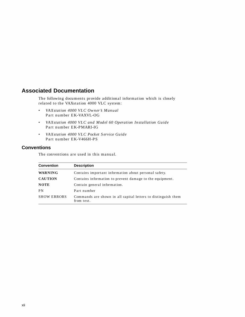
Associated DocumentationThe following documents provide additional information which is closelyrelated to the VAXstation 4000 VLC system:
• VAXstation 4000 VLC Owner’s ManualPart number EK-VAXVL-OG
• VAXstation 4000 VLC and Model 60 Operation Installation GuidePart number EK-PMARI-IG
• VAXstation 4000 VLC Pocket Service GuidePart number EK-V466H-PS
ConventionsThe conventions are used in this manual.
Convention Description
WARNING Contains important information about personal safety.
CAUTION Contains information to prevent damage to the equipment.
NOTE Contain general information.
PN Part number
SHOW ERRORS Commands are shown in all capital letters to distinguish themfrom text.
xii
1VAXstation 4000 VLC System Components
This chapter describes the modules and features of the VAXstation 4000 VLCsystem. Information about the central processor (CPU), main memory, networkinterface, SCSI controller, and other components of the system are included.
1.1 OverviewThe VAXstation 4000 VLC system module (PN 54-20768-01) forms the basisof the entire system. The VAXstation 4000 VLC system is a single-userengineering workstation, which includes the following:
• LK401 keyboard
• VSXXX-AA mouse or VSXXX-AB tablet
• Monochrome or color video monitor
• Mass storage device
• SCSI Ethernet controllers
VAXstation 4000 VLC System Components 1–1
VAXstation 4000 VLC System Components1.1 Overview
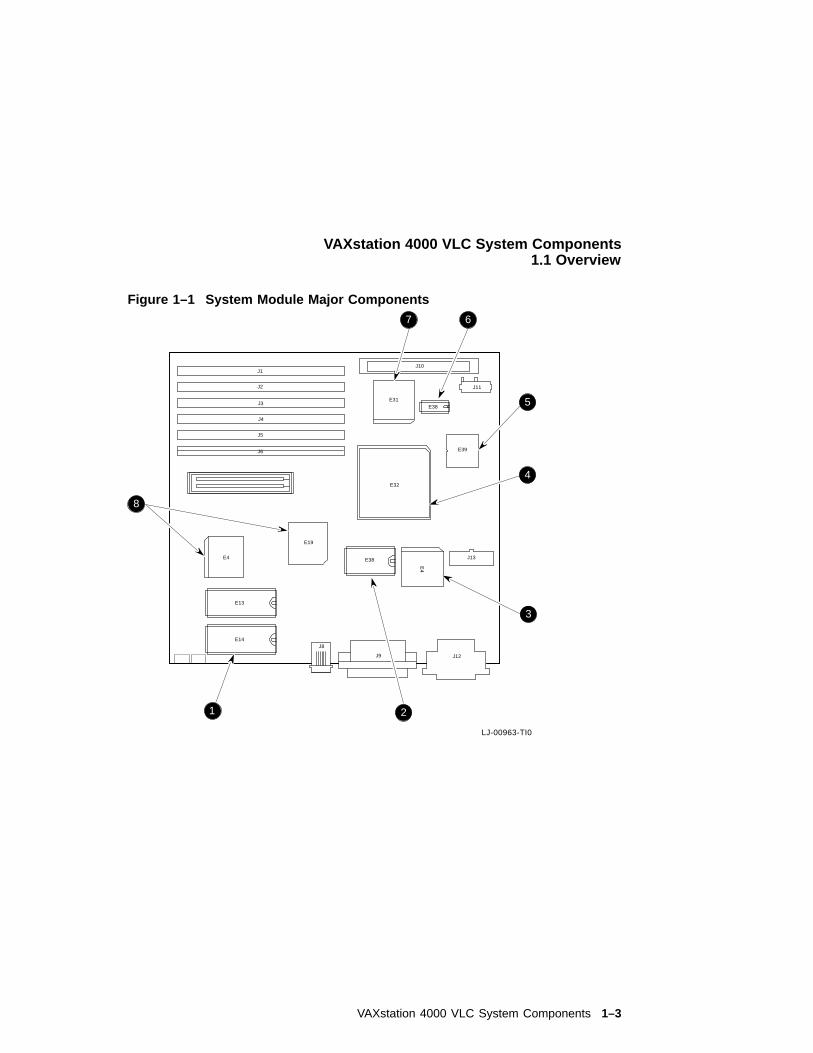
Figure 1–1 shows the major components of the system module.
! Base system ROMs
" TOY clock
# SCSI controller
$ S-chip
% SOC chip
& Ethernet address ROM
' Ethernet controller
( VAXstation 4000 VLC ASICs (Application Specific Intregated Circuits)
1–2 VAXstation 4000 VLC System Components
VAXstation 4000 VLC System Components1.1 Overview
Figure 1–1 System Module Major Components
LJ-00963-TI0
E39
J13
J12J9
J8
E13
E14
E38
E38
J11
J10
E31
E4
E19
J1
J2
J3
J4
J5
J6
E32
E4
7 6
5
4
3
21
8
VAXstation 4000 VLC System Components 1–3
VAXstation 4000 VLC System Components1.1 Overview
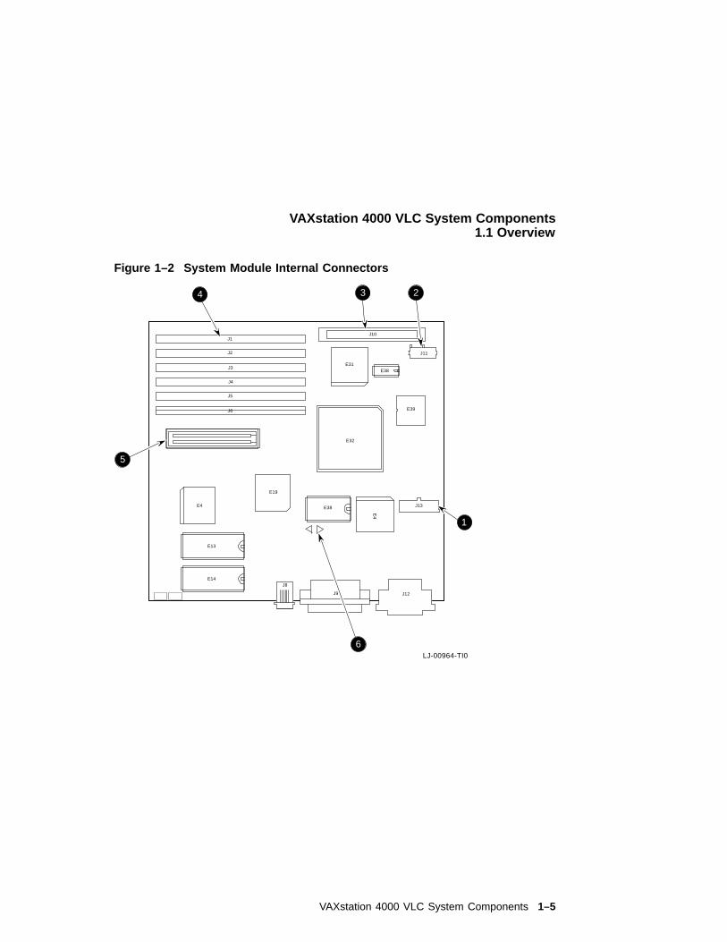
Figure 1–2 shows the internal connector locations of the system module. Section 2.1.3and Section 2.1.5 describe the system module external connectors.
! Power connector
" Mass storage connector
# SCSI connector
$ Memory module connectors
% Graphics module connector
& NVR reset pads
1–4 VAXstation 4000 VLC System Components
VAXstation 4000 VLC System Components1.1 Overview
Figure 1–2 System Module Internal Connectors
LJ-00964-TI0
E39
J13
J12J9
J8
E13
E14
E38
E38
J11
J10
E31
E4
E19
J1
J2
J3
J4
J5
J6
E32
E4
3 2
1
6
4
5
VAXstation 4000 VLC System Components 1–5
VAXstation 4000 VLC System Components1.2 Central Processor Unit
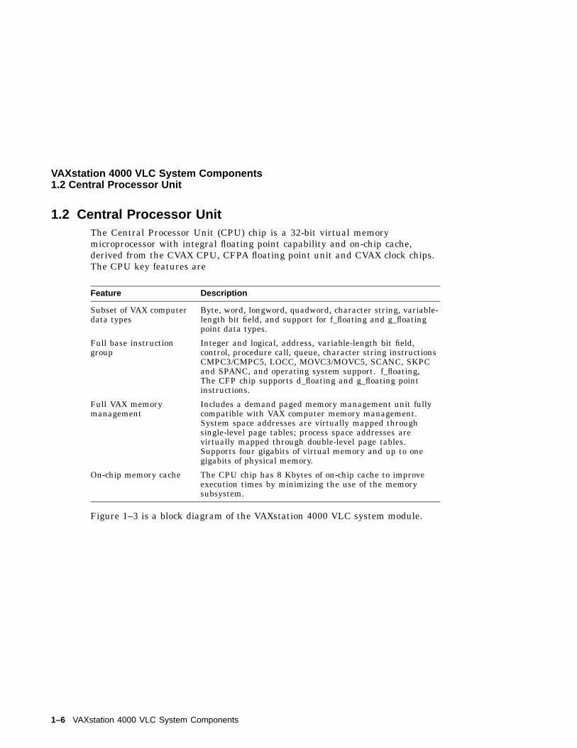
1.2 Central Processor UnitThe Central Processor Unit (CPU) chip is a 32-bit virtual memorymicroprocessor with integral floating point capability and on-chip cache,derived from the CVAX CPU, CFPA floating point unit and CVAX clock chips.The CPU key features are
Feature Description
Subset of VAX computerdata types
Byte, word, longword, quadword, character string, variable-length bit field, and support for f_floating and g_floatingpoint data types.
Full base instructiongroup
Integer and logical, address, variable-length bit field,control, procedure call, queue, character string instructionsCMPC3/CMPC5, LOCC, MOVC3/MOVC5, SCANC, SKPCand SPANC, and operating system support. f_floating,The CFP chip supports d_floating and g_floating pointinstructions.
Full VAX memorymanagement
Includes a demand paged memory management unit fullycompatible with VAX computer memory management.System space addresses are virtually mapped throughsingle-level page tables; process space addresses arevirtually mapped through double-level page tables.Supports four gigabits of virtual memory and up to onegigabits of physical memory.
On-chip memory cache The CPU chip has 8 Kbytes of on-chip cache to improveexecution times by minimizing the use of the memorysubsystem.
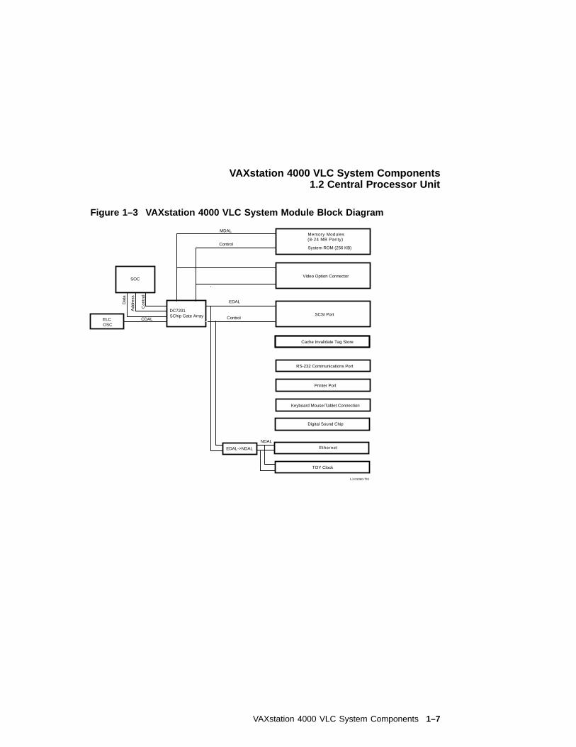
Figure 1–3 is a block diagram of the VAXstation 4000 VLC system module.
1–6 VAXstation 4000 VLC System Components
VAXstation 4000 VLC System Components1.2 Central Processor Unit
Figure 1–3 VAXstation 4000 VLC System Module Block Diagram
ELCOSC
CDAL
DC7201SChip Gate Array
MDAL
Control
EDAL
Control
EDAL->NDAL
NDAL
System ROM (256 KB)
Video Option Connector
SCSI Port
Cache Invalidate Tag Store
RS-232 Communications Port
Printer Port
Keyboard Mouse/Tablet Connection
Digital Sound Chip
TOY Clock
Dat
a
Con
trol
Add
ress
SOC
Memory Modules(8-24 MB Parity)
Ethernet
LJ-01060-TI0
VAXstation 4000 VLC System Components 1–7
VAXstation 4000 VLC System Components1.2 Central Processor Unit
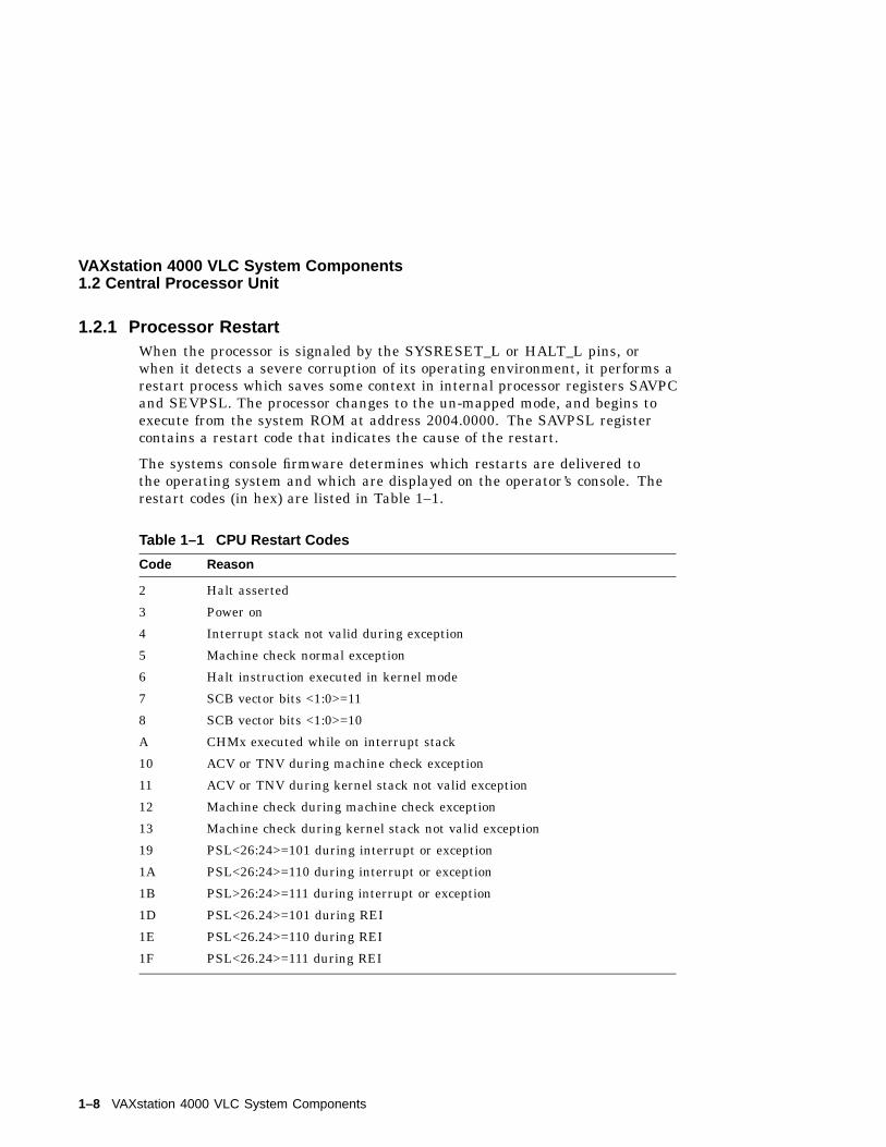
1.2.1 Processor RestartWhen the processor is signaled by the SYSRESET_L or HALT_L pins, orwhen it detects a severe corruption of its operating environment, it performs arestart process which saves some context in internal processor registers SAVPCand SEVPSL. The processor changes to the un-mapped mode, and begins toexecute from the system ROM at address 2004.0000. The SAVPSL registercontains a restart code that indicates the cause of the restart.
The systems console firmware determines which restarts are delivered tothe operating system and which are displayed on the operator’s console. Therestart codes (in hex) are listed in Table 1–1.
Table 1–1 CPU Restart Codes
Code Reason
2 Halt asserted
3 Power on
4 Interrupt stack not valid during exception
5 Machine check normal exception
6 Halt instruction executed in kernel mode
7 SCB vector bits <1:0>=11
8 SCB vector bits <1:0>=10
A CHMx executed while on interrupt stack
10 ACV or TNV during machine check exception
11 ACV or TNV during kernel stack not valid exception
12 Machine check during machine check exception
13 Machine check during kernel stack not valid exception
19 PSL<26:24>=101 during interrupt or exception
1A PSL<26:24>=110 during interrupt or exception
1B PSL>26:24>=111 during interrupt or exception
1D PSL<26.24>=101 during REI
1E PSL<26.24>=110 during REI
1F PSL<26.24>=111 during REI
1–8 VAXstation 4000 VLC System Components
VAXstation 4000 VLC System Components1.2 Central Processor Unit
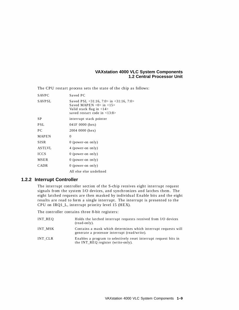
The CPU restart process sets the state of the chip as follows:
SAVPC Saved PC
SAVPSL Saved PSL <31:16, 7:0> in <31:16, 7:0>Saved MAPEN <0> in <15>Valid stack flag in <14>saved restart code in <13:8>
SP interrupt stack pointer
PSL 041F 0000 (hex)
PC 2004 0000 (hex)
MAPEN 0
SISR 0 (power-on only)
ASTLVL 4 (power-on only)
ICCS 0 (power-on only)
MSER 0 (power-on only)
CADR 0 (power-on only)
All else else undefined
1.2.2 Interrupt ControllerThe interrupt controller section of the S-chip receives eight interrupt requestsignals from the system I/O devices, and synchronizes and latches them. Theeight latched requests are then masked by individual Enable bits and the eightresults are read to form a single interrupt. The interrupt is presented to theCPU on IRQ1_L, interrupt priority level 15 (HEX).
The controller contains three 8-bit registers:
INT_REQ Holds the latched interrupt requests received from I/O devices(read-only).
INT_MSK Contains a mask which determines which interrupt requests willgenerate a processor interrupt (read/write).
INT_CLR Enables a program to selectively reset interrupt request bits inthe INT_REQ register (write-only).
VAXstation 4000 VLC System Components 1–9
VAXstation 4000 VLC System Components1.2 Central Processor Unit
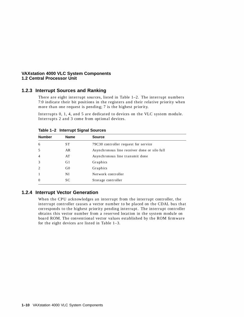
1.2.3 Interrupt Sources and RankingThere are eight interrupt sources, listed in Table 1–2. The interrupt numbers7:0 indicate their bit positions in the registers and their relative priority whenmore than one request is pending; 7 is the highest priority.
Interrupts 0, 1, 4, and 5 are dedicated to devices on the VLC system module.Interrupts 2 and 3 come from optional devices.
Table 1–2 Interrupt Signal Sources
Number Name Source
6 ST 79C30 controller request for service
5 AR Asynchronous line receiver done or silo full
4 AT Asynchronous line transmit done
3 G1 Graphics
2 G0 Graphics
1 NI Network controller
0 SC Storage controller
1.2.4 Interrupt Vector GenerationWhen the CPU acknowledges an interrupt from the interrupt controller, theinterrupt controller causes a vector number to be placed on the CDAL bus thatcorresponds to the highest priority pending interrupt. The interrupt controllerobtains this vector number from a reserved location in the system module onboard ROM. The conventional vector values established by the ROM firmwarefor the eight devices are listed in Table 1–3.
1–10 VAXstation 4000 VLC System Components
VAXstation 4000 VLC System Components1.2 Central Processor Unit
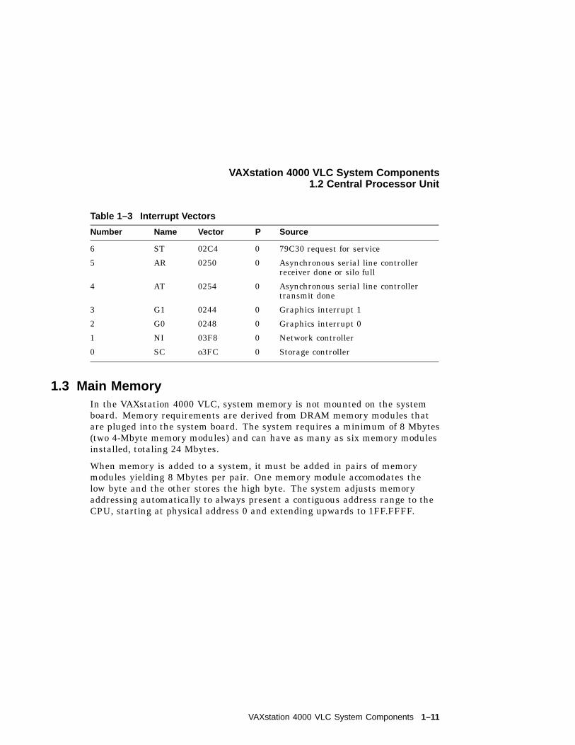
Table 1–3 Interrupt Vectors
Number Name Vector P Source
6 ST 02C4 0 79C30 request for service
5 AR 0250 0 Asynchronous serial line controllerreceiver done or silo full
4 AT 0254 0 Asynchronous serial line controllertransmit done
3 G1 0244 0 Graphics interrupt 1
2 G0 0248 0 Graphics interrupt 0
1 NI 03F8 0 Network controller
0 SC o3FC 0 Storage controller
1.3 Main MemoryIn the VAXstation 4000 VLC, system memory is not mounted on the systemboard. Memory requirements are derived from DRAM memory modules thatare pluged into the system board. The system requires a minimum of 8 Mbytes(two 4-Mbyte memory modules) and can have as many as six memory modulesinstalled, totaling 24 Mbytes.
When memory is added to a system, it must be added in pairs of memorymodules yielding 8 Mbytes per pair. One memory module accomodates thelow byte and the other stores the high byte. The system adjusts memoryaddressing automatically to always present a contiguous address range to theCPU, starting at physical address 0 and extending upwards to 1FF.FFFF.
VAXstation 4000 VLC System Components 1–11
VAXstation 4000 VLC System Components1.3 Main Memory
The S-chip arbitrates between, and services requests for, main memory cyclesfrom several sources: the Ethernet Controller (NI), Mass Storage Controller(SCSI), CPU, and Graphics Controller (GC) section of the S-chip. To minimizeinteraction between the requestors, the S-chip has three buses: the CDAL,which connects to the CPU; the EDAL, which connects to the Ethernetcontroller and the storage controller; and the MDAL, which connects to thememory system, including Video RAMs.
The S-chip is capable of performing several types of RAM cycles: longword,quadword, and octaword. Buffering between the requestors and the memoryallows these cycles to maximize the available memory bandwidth.
The Ethernet controller and SCSI controller are DMA devices. The graphicscontroller can generate addresses independently. All three of these devices mayattempt to write to memory locations that are currently cached. To maintaincache coherency, the CPU cache is checked and, if necessary, the entry isinvalidated for writes requested by any of these devices. This could imposea significant load on the CPU to check the potential invalidates. For thisreason the S-chip controls a separate invalidated filter that maintains a copyof the CPU cache tags. In this way only those writes that do require a cacheinvalidate can disturb the CPU.
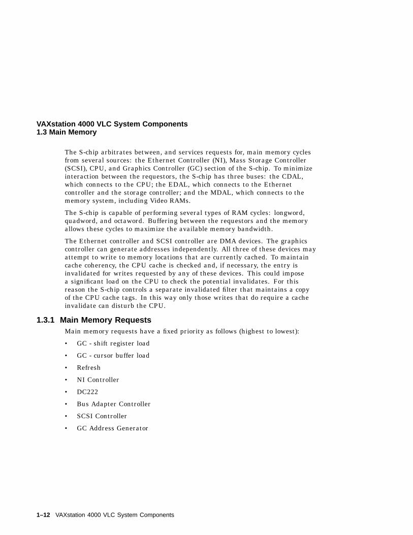
1.3.1 Main Memory RequestsMain memory requests have a fixed priority as follows (highest to lowest):
• GC - shift register load
• GC - cursor buffer load
• Refresh
• NI Controller
• DC222
• Bus Adapter Controller
• SCSI Controller
• GC Address Generator
1–12 VAXstation 4000 VLC System Components
VAXstation 4000 VLC System Components1.3 Main Memory
1.3.2 DMA MappingThe Ethernet and SCSI controllers access memory using a translation tablestored in main memory. A Map Base Address Register (MAP_BASE) withinthe S-chip points to this reserved section of memory. The 32,768 longwordsextending upwards from MAP_BASE provide translations for the page addresssupplied by either DMA device. Each DMA device has a two-entry cache ofcurrent translations kept in the S-chip. The operating system allocates entriesfor each DMA device in the translation table.
1.3.3 TranslationEach DMA controller has a 24-bit address counter for DMA transfers that hasa page field (15-bits) and an address-within-page field (9-bits). When a DMAcontroller presents an address to the S-chip to perform a DMA cycle to or frommain memory, the S-chip translates the address supplied using MAP_BASEand the translation table contained in main memory as follows.
The bits <23:09> of the page field (the DMA controller-supplied address) arecompared to the address value held in either the read or write translationcache for that DMA device. If the addresses match and if the entry is markedvalid, the associated page address held in a field of the cache entry is connectedwith the address-within-page field of the supplied address to form the actualaddress to be used and the DMA cycle proceeds.
If the address match failed, indicating that the DMA transfer is to an addresson a different page than the last DMA transfer the device initiated, bits<23:09> of the DMA address supplied are connected with bits <24:17> ofMAP_BASE to form a new 23-bit longword aligned map register address. Thisaddress is used to retrieve data from the translation table in main memory.Bits <15:00> of the data that returned from memory are connected withthe original address-within-page bits supplied by the controller to form a25-bit address that is the actual address to be accessed. Bits <15:00> thatwere retrieved from the translation table are stored as a new value in theappropriate translation cache associated with the DMA device and the valid bitset for the entry.
VAXstation 4000 VLC System Components 1–13
VAXstation 4000 VLC System Components1.4 ROM Memory
1.4 ROM MemoryThe VAXstation 4000 VLC ROM contains the processor restart, diagnostic,console code, and bootstrap programs.
1.4.1 System ROMThe system ROM data is stored in two EPROM chips that hold 256 Kbytes ofdata. The data is in physical addresses 2004.0000 through 2007.FFFF. TheROM data path is 32 bits wide. Some physical addresses in the ROM havefixed use.
2004.0000 Processor restart address. The processor begins execution at thisaddress in non-mapped mode when a processor restart occurs.
2004.0004 System type register SYS_TYPE. The contents of this longwordsupplement the internal processor SID register to identify theprocessor and system type.
2004.0020 Interrupt vector numbers. Eleven consecutive longwords startingat this address are automatically referenced by the hardware tosupply the interrupt vector numbers for the eleven interrupt sourcesconnected to the interrupt controller plus the three unused hardwareinterrupts of the CPU.
1.4.2 Network Address ROMA 32-byte ROM on the system module contains the network address for thesystem. Information from this ROM is read in the low-order bytes of 32consecutive longwords at physical addresses 2009.0000 through 2009.007C.The network address occupies the first six bytes (addresses 2009.0000 through2009.0014). The byte at 2009.0000 is the first byte to be transmitted orreceived in an address field of an Ethernet packet: its low-order bit istransmitted or received first in the serial bit stream.
1–14 VAXstation 4000 VLC System Components
VAXstation 4000 VLC System Components1.5 Graphics Controller
1.5 Graphics ControllerThe graphics controller is a part of the memory control section of the S-chip.The graphics controller competes with other devices for memory cycles.Graphics operations, however, have the lowest priority of all devices requestingmemory cycles.
The graphics controller supports both 8-plane and single-plane 2D graphicsand can execute the most commonly used primitives of DECwindows. Thecontroller draws by way of linear addressing. The types of operationssupported are
• Lines
• One, two, and three operand rasterops
• Text
Rasterops can be
• Solid colored
• Tiled
• Stippled
• Color expanded
• Plane compacted
All operations can be performed to the frame buffer and non-displayable mainsystem memory using virtual addressing with multiple clipping rectangles foroverlapping window hardware support.
The VAXstation 4000 VLC workstation has no video frame buffer; one ofseveral video option modules can be added to the system module to providethe frame buffer from which pixels are output to the monitor. The videooption modules carry video RAMS, pixel timing, and output digital-to-analogconversion/level sifters. The interface to the system module is at the "nibble"level, one quarter of the pixel rate.
VAXstation 4000 VLC System Components 1–15
VAXstation 4000 VLC System Components1.5 Graphics Controller
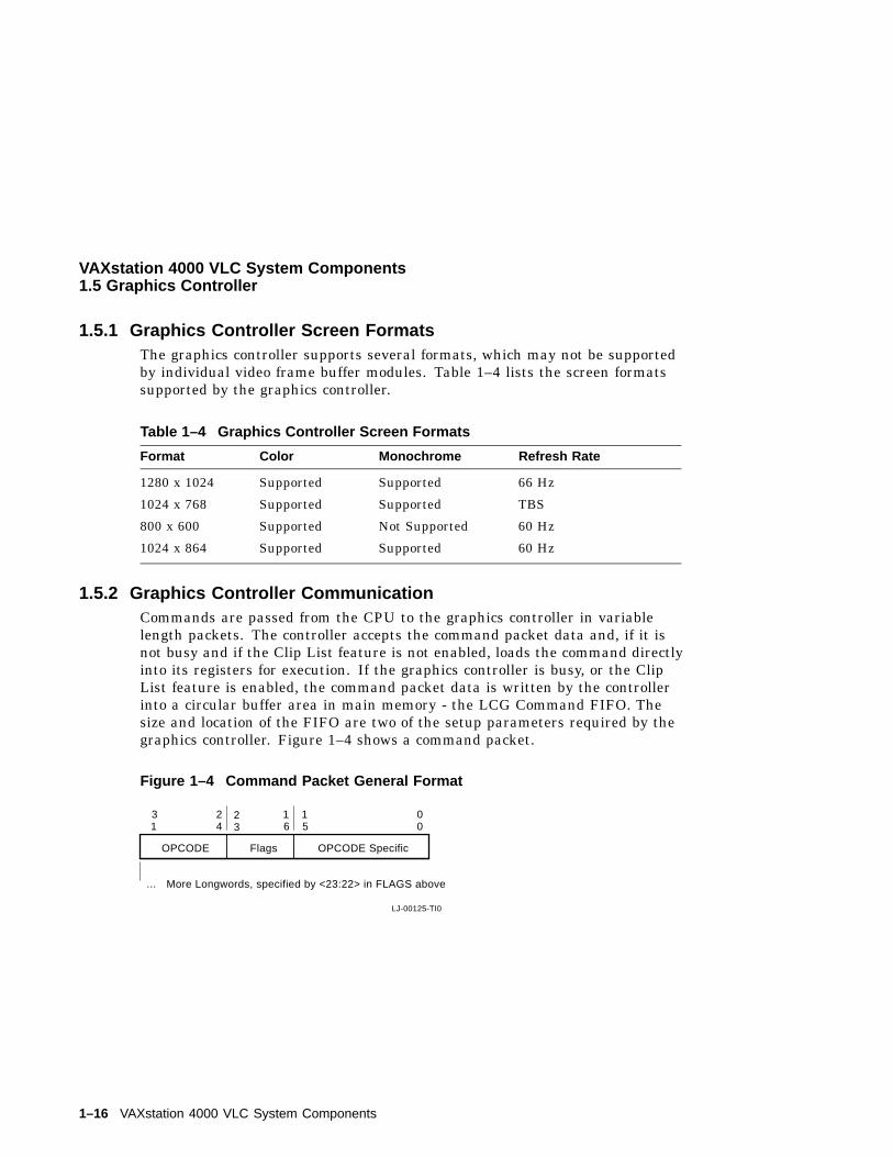
1.5.1 Graphics Controller Screen FormatsThe graphics controller supports several formats, which may not be supportedby individual video frame buffer modules. Table 1–4 lists the screen formatssupported by the graphics controller.
Table 1–4 Graphics Controller Screen Formats
Format Color Monochrome Refresh Rate
1280 x 1024 Supported Supported 66 Hz
1024 x 768 Supported Supported TBS
800 x 600 Supported Not Supported 60 Hz
1024 x 864 Supported Supported 60 Hz
1.5.2 Graphics Controller CommunicationCommands are passed from the CPU to the graphics controller in variablelength packets. The controller accepts the command packet data and, if it isnot busy and if the Clip List feature is not enabled, loads the command directlyinto its registers for execution. If the graphics controller is busy, or the ClipList feature is enabled, the command packet data is written by the controllerinto a circular buffer area in main memory - the LCG Command FIFO. Thesize and location of the FIFO are two of the setup parameters required by thegraphics controller. Figure 1–4 shows a command packet.
Figure 1–4 Command Packet General Format
OPCODE Specific
LJ-00125-TI0
FlagsOPCODE
More Longwords, specified by <23:22> in FLAGS above
31
24
23
16
15
00
...
1–16 VAXstation 4000 VLC System Components
VAXstation 4000 VLC System Components1.6 Serial Line Controller Feature
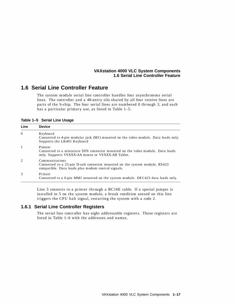
1.6 Serial Line Controller FeatureThe system module serial line controller handles four asynchronous seriallines. The controller and a 48-entry silo shared by all four receive lines areparts of the S-chip. The four serial lines are numbered 0 through 3, and eachhas a particular primary use, as listed in Table 1–5.
Table 1–5 Serial Line Usage
Line Device
0 KeyboardConnected to 4-pin modular jack (MJ) mounted on the video module. Data leads only.Supports the LK401 Keyboard
1 PointerConnected to a miniature DIN connector mounted on the video module. Data leadsonly. Supports VSXXX-AA mouse or VSXXX-AB Tablet.
2 CommunicationsConnected to a 25-pin D-sub connector mounted on the system module, RS423compatible. Data leads plus modem control signals.
3 PrinterConnected to a 6-pin MMJ mounted on the system module. DEC423 data leads only.
Line 3 connects to a printer through a BC16E cable. If a special jumper isinstalled in 5 on the system module, a break condition sensed on this linetriggers the CPU halt signal, restarting the system with a code 2.
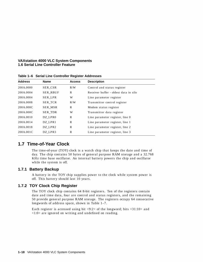
1.6.1 Serial Line Controller RegistersThe serial line controller has eight addressable registers. These registers arelisted in Table 1–6 with the addresses and names.
VAXstation 4000 VLC System Components 1–17
VAXstation 4000 VLC System Components1.6 Serial Line Controller Feature
Table 1–6 Serial Line Controller Register Addresses
Address Name Access Description
200A.0000 SER_CSR R/W Control and status register
200A.0004 SER_RBUF R Receiver buffer - oldest data in silo
200A.0004 SER_LPR W Line parameter register
200A.0008 SER_TCR R/W Transmitter control register
200A.000C SER_MSR R Modem status register
200A.000C SER_TDR W Transmitter data register
200A.0010 DZ_LPR0 R Line parameter register, line 0
200A.0014 DZ_LPR1 R Line parameter register, line 1
200A.0018 DZ_LPR2 R Line parameter register, line 2
200A.001C DZ_LPR3 R Line parameter register, line 3
1.7 Time-of-Year ClockThe time-of-year (TOY) clock is a watch chip that keeps the date and time ofday. The chip contains 50 bytes of general purpose RAM storage and a 32.768KHz time base oscillator. An internal battery powers the chip and oscillatorwhile the system is off.
1.7.1 Battery BackupA battery in the TOY chip supplies power to the clock while system power isoff. This battery should last 10 years.
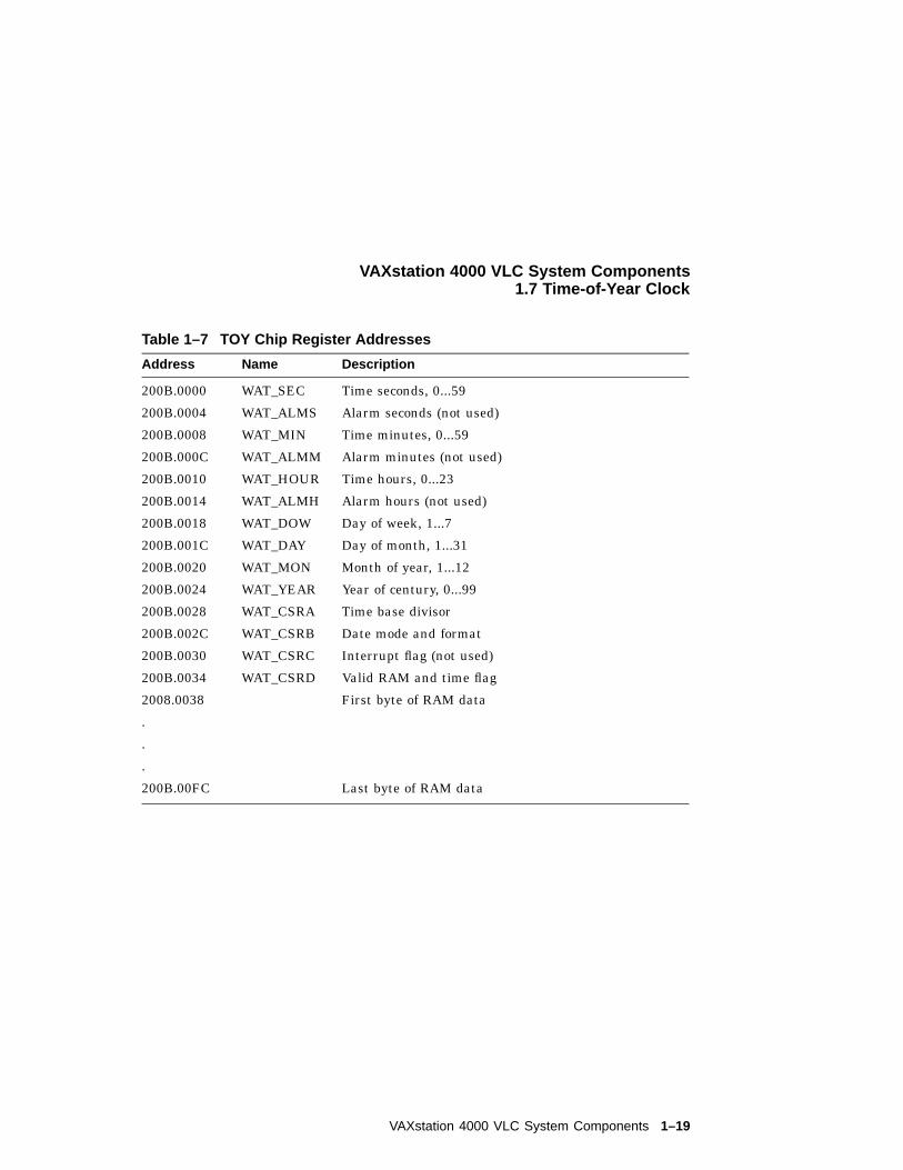
1.7.2 TOY Clock Chip RegisterThe TOY clock chip contains 64 8-bit registers. Ten of the registers containdate and time data, four are control and status registers, and the remaining50 provide general purpose RAM storage. The registers occupy 64 consecutivelongwords of address space, shown in Table 1–7.
Each register is accessed using bit <9:2> of the longword; bits <31:10> and<1:0> are ignored on writing and undefined on reading.
1–18 VAXstation 4000 VLC System Components
VAXstation 4000 VLC System Components1.7 Time-of-Year Clock
Table 1–7 TOY Chip Register Addresses
Address Name Description
200B.0000 WAT_SEC Time seconds, 0...59
200B.0004 WAT_ALMS Alarm seconds (not used)
200B.0008 WAT_MIN Time minutes, 0...59
200B.000C WAT_ALMM Alarm minutes (not used)
200B.0010 WAT_HOUR Time hours, 0...23
200B.0014 WAT_ALMH Alarm hours (not used)
200B.0018 WAT_DOW Day of week, 1...7
200B.001C WAT_DAY Day of month, 1...31
200B.0020 WAT_MON Month of year, 1...12
200B.0024 WAT_YEAR Year of century, 0...99
200B.0028 WAT_CSRA Time base divisor
200B.002C WAT_CSRB Date mode and format
200B.0030 WAT_CSRC Interrupt flag (not used)
200B.0034 WAT_CSRD Valid RAM and time flag
2008.0038 First byte of RAM data
.
.
.
200B.00FC Last byte of RAM data
VAXstation 4000 VLC System Components 1–19
VAXstation 4000 VLC System Components1.7 Time-of-Year Clock
Note
Because each register spans two bytes on the system bus, only wordor longword instructions can be used to manipulate these registers.Instructions for modifying bits such as BBSS, BBSC, BBCC and BBCScannot be used because they generate byte instructions for read-modify-write cycles which corrupt that portion of the register not beingaccessed.
1.8 Network Controller FeatureThe VAXtation 4000 VLC workstation can be connected to an Ethernetnetwork by connecting a transceiver cable to a standard Ethernet connector.The network controller is part of the system module and consists of a LanceEthernet controller chip, a serial interface adapter, an Ethernet transceiverchip, and a 15-pin D-sub connector for standard Ethernet transceiver cable.
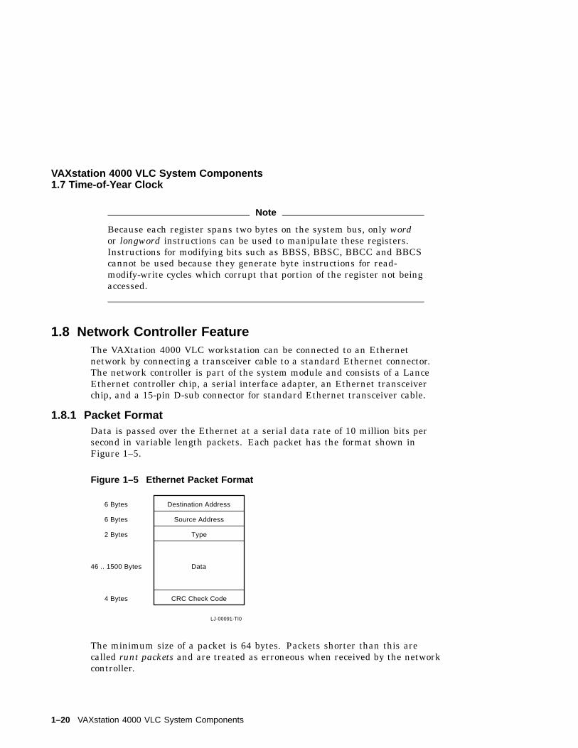
1.8.1 Packet FormatData is passed over the Ethernet at a serial data rate of 10 million bits persecond in variable length packets. Each packet has the format shown inFigure 1–5.
Figure 1–5 Ethernet Packet Format
Destination Address
Source Address
Type
Data
CRC Check Code
LJ-00091-TI0
6 Bytes
6 Bytes
2 Bytes
46 .. 1500 Bytes
4 Bytes
The minimum size of a packet is 64 bytes. Packets shorter than this arecalled runt packets and are treated as erroneous when received by the networkcontroller.
1–20 VAXstation 4000 VLC System Components
VAXstation 4000 VLC System Components1.8 Network Controller Feature
1.8.2 Network AddressesEthernet network addresses are 48 bits (6 bytes) long. There are two types ofnetwork addresses.
• Physical Address: The unique address associated with a particularworkstation on the Ethernet network. Should be different from thephysical address of any other workstation on that Ethernet network.
• Multicast Address: A multi-destination address associated with one ormore workstations on a given Ethernet network (also called a logicaladdress). There are two kinds of multicast addresses.
Multicast-Group Address: An address associated by higher-levelconvention with a group of logically related workstations.
Broadcast Address: A pre-defined multicast address which denotes theset of all workstations on the Ethernet network.
Bit 0 (the least significant bit of the first byte) of an address denotes the typeof address.
• 0 = Physical addresses
• 1 = Multicast addresses
For either type of address, the remaining 47 bits form the address value. Avalue of 48 ones is always treated as the broadcast address.
The physical address of each VAXstation 4000 VLC workstation is determinedbefore the system ships from the factory. The physical address is stored in theEthernet Address ROM on the system module.
1.9 SCSI Controller FeatureThe controller conforms to the ANSI Small Computer System Interface (SCSI)specification. It has a single port, connecting to devices within the systemenclosure and allowing for external expansion.
The SCSI controller interface is a single-ended, bi-directional, 8-bit wide bus.In addition to the system module, as many as seven devices can be attatchedto the controller. Devices can be either an initiator or target. An initiatororiginates an operation by sending a command to a specific target. A targetperforms an operation that was requested by an initiator. The VAXstation 4000VLC workstation is always the initiator and all other SCSI devices attached toit are targets.
VAXstation 4000 VLC System Components 1–21
VAXstation 4000 VLC System Components1.9 SCSI Controller Feature
Each device attached to the SCSI bus is identified by a unique device IDnumber in the range 0 to 7. The device IDs of the initiator and targets areboth placed on the data bus by asserting the data bits corresponding to thedevice ID number. This number is controlled by programs that drive the SCSIinterface and is not fixed in the VAXstation 4000 VLC workstation hardware.
The interface consists of 18 signal lines; some are driven by initiators and someby targets. The bus is permanently terminated at the SCSI controller end andmust always be terminated at each end. External termination can take placeeither at
• The expansion connector on the rear of the system enclosure
• The second expansion connector on the last storage expansion unit in theSCSI chain.
1.9.1 SCSI Bus SignalsThe following is a brief description of SCSI bus signals.
• DB7..0 and DBP
Comprise an 8-bit parallel data bus with an associated odd parity bit. Theuse of the parity bit is optional but strongly encouraged. These lines can bedriven by either an initiator or a terminator, depending upon the directionof data transfer.
• RST
Signals all devices on the SCSI bus to reset to their initial power-on states.Thereafter, it should be asserted only as a last resort during error recoverysince it indirectly affects all devices on the bus. An RST signal generatedby some other device on the bus causes an internal reset of he 53C94 chipused in this controller and sets the interrupt request bit (INT in registerSCS_STATUS).
• BSY and SEL
Are used by initiators and targets during the arbitration, selection, andre-selection bus phases to establish or resume a logical connection betweenan initiator and a target. Once the connection is established, the targetasserts BSY and the SEL signal is not driven by anything.
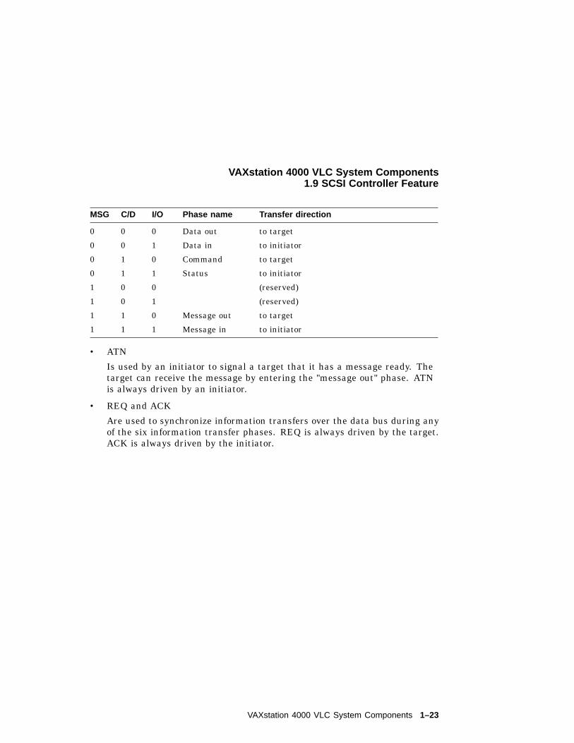
• C/D, I/O and MSG
Collectively indicate one of six possible information transfer phases,according to the following table. These signals are always driven by thetarget device.
1–22 VAXstation 4000 VLC System Components
VAXstation 4000 VLC System Components1.9 SCSI Controller Feature
MSG C/D I/O Phase name Transfer direction
0 0 0 Data out to target
0 0 1 Data in to initiator
0 1 0 Command to target
0 1 1 Status to initiator
1 0 0 (reserved)
1 0 1 (reserved)
1 1 0 Message out to target
1 1 1 Message in to initiator
• ATN
Is used by an initiator to signal a target that it has a message ready. Thetarget can receive the message by entering the "message out" phase. ATNis always driven by an initiator.
• REQ and ACK
Are used to synchronize information transfers over the data bus during anyof the six information transfer phases. REQ is always driven by the target.ACK is always driven by the initiator.
VAXstation 4000 VLC System Components 1–23
2VAXstation 4000 VLC System
Configuration
This chapter describes the system box used with the VAXstation 4000 VLCworkstation.
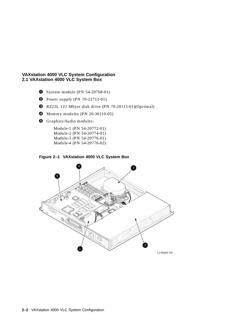
2.1 VAXstation 4000 VLC System BoxThe system box is used for desktop installation of the VAXstation 4000 VLCsystem. Figure 2–1 shows the system box and its components. Refer toAppendix D for a complete list of field replaceable units and part numbers.
VAXstation 4000 VLC System Configuration 2–1
VAXstation 4000 VLC System Configuration2.1 VAXstation 4000 VLC System Box
! System module (PN 54-20768-01)
" Power supply (PN 70-22712-01)
# RZ23L 121 Mbyte disk drive (PN 70-28115-01)(Optional)
$ Memory modules (PN 20-36110-05)
% Graphics/Audio modules:
Module-1 (PN 54-20772-01)Module-2 (PN 54-20774-01)Module-3 (PN 54-20776-01)Module-4 (PN 54-20776-02)
Figure 2–1 VAXstation 4000 VLC System Box
22%
38%
LJ-00960-TI0
J12
J2
J3J4
J5J6
3
12
4
5
2–2 VAXstation 4000 VLC System Configuration
VAXstation 4000 VLC System Configuration2.1 VAXstation 4000 VLC System Box
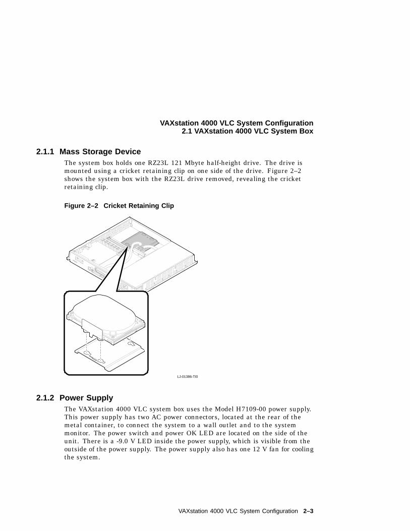
2.1.1 Mass Storage DeviceThe system box holds one RZ23L 121 Mbyte half-height drive. The drive ismounted using a cricket retaining clip on one side of the drive. Figure 2–2shows the system box with the RZ23L drive removed, revealing the cricketretaining clip.
Figure 2–2 Cricket Retaining Clip
C1C2
LJ-01386-TI0
2.1.2 Power SupplyThe VAXstation 4000 VLC system box uses the Model H7109-00 power supply.This power supply has two AC power connectors, located at the rear of themetal container, to connect the system to a wall outlet and to the systemmonitor. The power switch and power OK LED are located on the side of theunit. There is a -9.0 V LED inside the power supply, which is visible from theoutside of the power supply. The power supply also has one 12 V fan for coolingthe system.
VAXstation 4000 VLC System Configuration 2–3
VAXstation 4000 VLC System Configuration2.1 VAXstation 4000 VLC System Box
The power supply has an automatic voltage select (AVS ) circuit toautomatically select the AC input of either 100 to 120 Vac or 220 to 240Vac. The supply is a 106 watt (W) unit. It supplies the following voltages:
Volts dc Ampere
+5.1 10.0
+3.3 1.98
+12.1 3.5
-12.0 0.39
The H7109 supplies power to the following components:
• System module (Supplies power for option modules installed in the system.)
• Mass storage devices
• Cooling fan
• AC Power for system monitor
• LCG Controllor module
2.1.2.1 Power Supply SpecificationsThe following tables list the power supply specifications.
Parameter Specifications
Line voltage 120 V 240 V
Voltage tolerance 88 V to 132 V 176 V to 264 V
Frequency 60 Hz 50 Hz
Frequency tolerance 47 Hz to 63 Hz 47 Hz to 63 Hz
Input current 2.7 A (max.)4.0 (max)
1.2 A (max) PS only2.0 A (max) AUX only
Inrush current 45.0 A PS only(max.) cold
45.0 A PS only(max.) cold
Power consumption(max.)
163 W 163 W
2–4 VAXstation 4000 VLC System Configuration
VAXstation 4000 VLC System Configuration2.1 VAXstation 4000 VLC System Box
Power Supply Output Characteristics
Parameter Specifications
Minimum Typical Maximum
+5.1 V reg.Short term
4.90 V 5.05 V 5.20 V
+5.1 V reg.Long term
+4.85 V +5.10 V +5.25 V
+12.1 V reg.Short term
+11.70 V +12.10 V +12.50 V
+12.1 V reg.Long term
+11.50 V +12.10 V +12.70 V
-12.0 V reg.Long term
-11.40 V -12.00 V -12.60 V
+3.3 V Long term +3.13 V +3.3 V +3.46 V
Load range+3.3 V+5.1 V+12.1 V-12.0 V
o.80 A1.2 A0.18 A0.14 A
1.98 A10.0 A3.5 A0.39 A
Ripple and noise1Hz to 10Hz+3.3 V+5.1 V+12.1 V-12.0 V
20.0 mV30.0mV50.0 mV
30.0 mV50.0 mV70.0 mV120.0 mV
Ripple and noise(except +5.1 V and +3.3 V)10 MHz to 50 MHz
1.0% 2.0%
Ripple and noise10 MHz to 50 MHz+5.1 V+3.3 V
30 mV20 mV
50 mV30 mV
VAXstation 4000 VLC System Configuration 2–5
VAXstation 4000 VLC System Configuration2.1 VAXstation 4000 VLC System Box
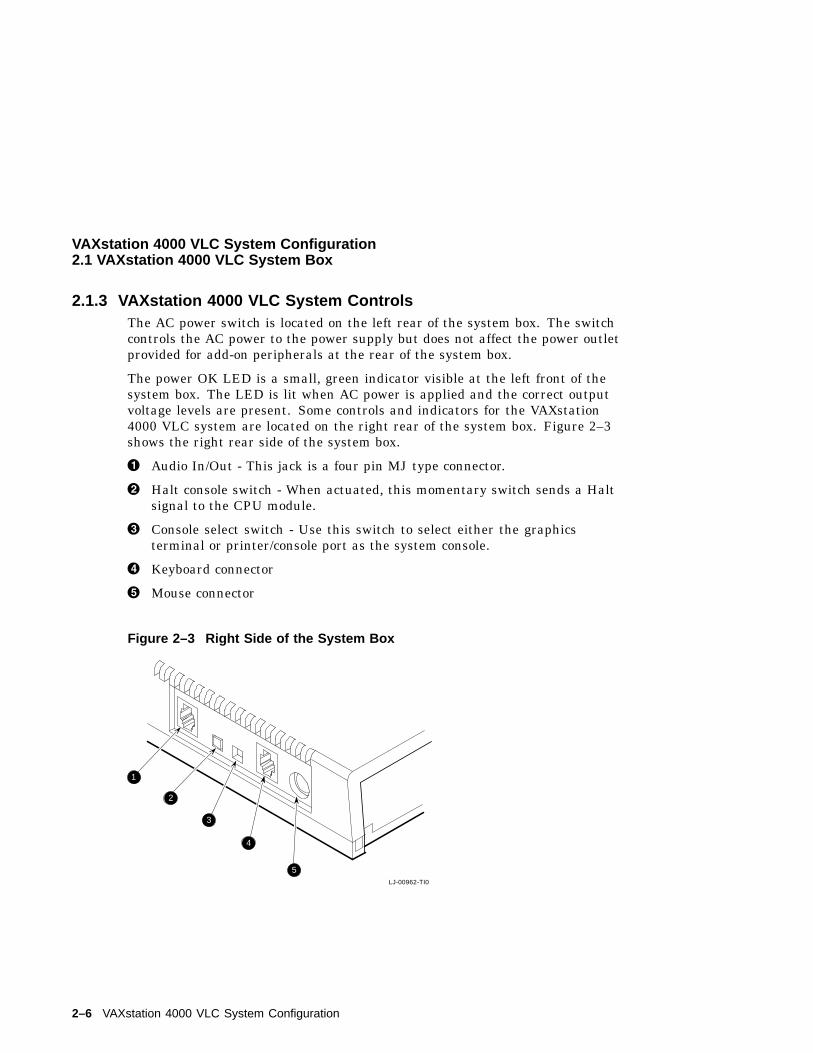
2.1.3 VAXstation 4000 VLC System ControlsThe AC power switch is located on the left rear of the system box. The switchcontrols the AC power to the power supply but does not affect the power outletprovided for add-on peripherals at the rear of the system box.
The power OK LED is a small, green indicator visible at the left front of thesystem box. The LED is lit when AC power is applied and the correct outputvoltage levels are present. Some controls and indicators for the VAXstation4000 VLC system are located on the right rear of the system box. Figure 2–3shows the right rear side of the system box.
! Audio In/Out - This jack is a four pin MJ type connector.
" Halt console switch - When actuated, this momentary switch sends a Haltsignal to the CPU module.
# Console select switch - Use this switch to select either the graphicsterminal or printer/console port as the system console.
$ Keyboard connector
% Mouse connector
Figure 2–3 Right Side of the System Box
LJ-00962-TI0
1
2
3
4
5
2–6 VAXstation 4000 VLC System Configuration
VAXstation 4000 VLC System Configuration2.1 VAXstation 4000 VLC System Box
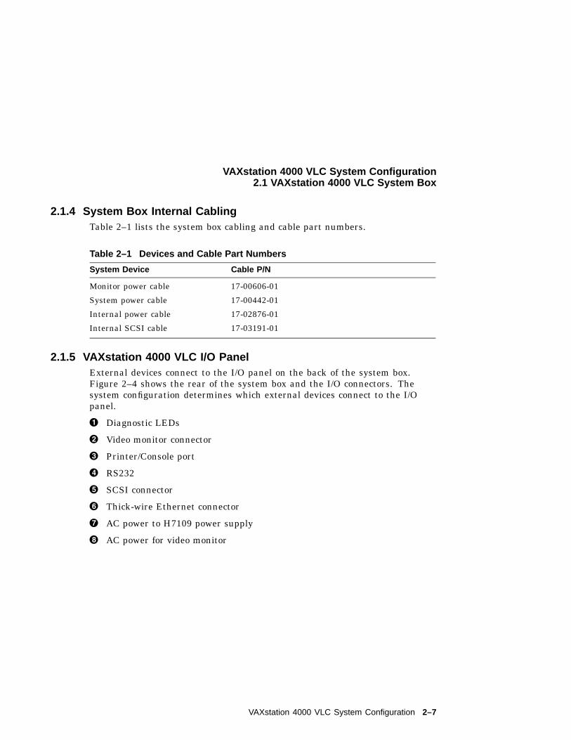
2.1.4 System Box Internal CablingTable 2–1 lists the system box cabling and cable part numbers.
Table 2–1 Devices and Cable Part Numbers
System Device Cable P/N
Monitor power cable 17-00606-01
System power cable 17-00442-01
Internal power cable 17-02876-01
Internal SCSI cable 17-03191-01
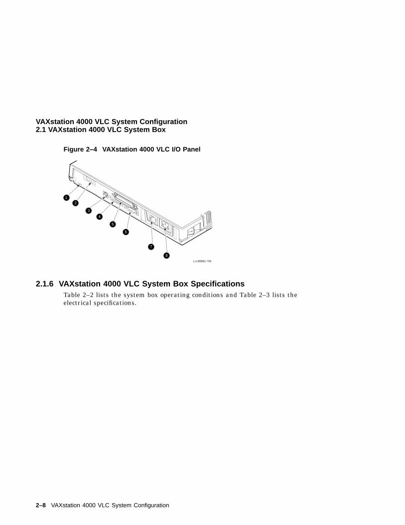
2.1.5 VAXstation 4000 VLC I/O PanelExternal devices connect to the I/O panel on the back of the system box.Figure 2–4 shows the rear of the system box and the I/O connectors. Thesystem configuration determines which external devices connect to the I/Opanel.
! Diagnostic LEDs
" Video monitor connector
# Printer/Console port
$ RS232
% SCSI connector
& Thick-wire Ethernet connector
' AC power to H7109 power supply
( AC power for video monitor
VAXstation 4000 VLC System Configuration 2–7
VAXstation 4000 VLC System Configuration2.1 VAXstation 4000 VLC System Box
Figure 2–4 VAXstation 4000 VLC I/O Panel
LJ-00961-TI0
12
3
4
5
6
7
8
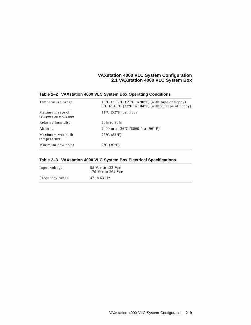
2.1.6 VAXstation 4000 VLC System Box SpecificationsTable 2–2 lists the system box operating conditions and Table 2–3 lists theelectrical specifications.
2–8 VAXstation 4000 VLC System Configuration
VAXstation 4000 VLC System Configuration2.1 VAXstation 4000 VLC System Box
Table 2–2 VAXstation 4000 VLC System Box Operating Conditions
Temperature range 15°C to 32°C (59°F to 90°F) (with tape or floppy)0°C to 40°C (32°F to 104°F) (without tape of floppy)
Maximum rate oftemperature change
11°C (52°F) per hour
Relative humidity 20% to 80%
Altitude 2400 m at 36°C (8000 ft at 96° F)
Maximum wet bulbtemperature
28°C (82°F)
Minimum dew point 2°C (36°F)
Table 2–3 VAXstation 4000 VLC System Box Electrical Specifications
Input voltage 88 Vac to 132 Vac176 Vac to 264 Vac
Frequency range 47 to 63 Hz
VAXstation 4000 VLC System Configuration 2–9
3VAXstation 4000 VLC Firmware
This chapter is an overview of the VAXstation 4000 VLC system firmware. Thefirmware is located in two EPROMs that hold a total of 256K bytes of data.The firmware has the following four areas of operation:
• Power-Up initialization code
• Console
• Extended self test code
• Utilities
VAXstation 4000 VLC Firmware 3–1
VAXstation 4000 VLC Firmware3.1 Power-Up Initialization Code
3.1 Power-Up Initialization CodeThe power-up initialization code executes when power to the system is turnedon. The power-up initialization code sequence is:
1. The system tests enough memory to allow it to bring up the console forbuilding console and device structures.
2. The system checks its configuration for optional devices.
3. The system tests the Time-of-Year (TOY) clock and the non-volatile RAM.If the test fails, the power-up test stops.
4. The system constructs the master configuration table (MCT), the deviceconfiguration Table (DCT), driver descriptor, shared console interface area,and a blank page frame map.
5. The system tests the serial lines. If the test fails, the console terminal isnot enabled.
Note
If the alternate console switch is set for alternate console, the terminalconnected to line three of the serial port is used as the console.
6. The system invokes the console device initialization routine.
The system type and ROM ID are displayed on the console device followedby its memory capacity and the Ethernet address.
7. The system test dispatcher tests the functional blocks of the system. Thedispatcher runs the tests in the following order:
a. Memory test
b. Clock test
c. Memory management unit (MMU) test
d. Floating point unit (FPU) test
e. Interval timer test
f. Miscellaneous system board test (checksums, interrupt controller test,Ethernet ID ROM)
g. Network controller test
h. SCSI Controller test
i. Sound chip test
3–2 VAXstation 4000 VLC Firmware
VAXstation 4000 VLC Firmware3.1 Power-Up Initialization Code
If any device fails during testing, the dispatcher continues to test theremaining devices until all tests are completed.
Note
If halts are enabled the console prompt (>>>) displays. If halts aredisabled, the system autoboots using the default device stored in NVRor the Ethernet,if no device is specified.
3.2 Console OverviewConsole mode allows operation of a console device. The console device can be
• A workstation video device and LK401 keyboard and mouse
• A terminal connected to line three of the serial port
• A remote system connected over the Ethernet
Console mode can be entered if
• The console HALT parameter is set to halt (3) at power-up.
• A HALT instruction is executed with the HALT parameter set to halt (3).
• A severe processor condition occurs (such as an invalid interrupt stack).
• An external HALT is detected (pressing the halt button at the front panel)
In console mode input and output (I/O) routines are used by the
• Power-Up self test
• Extended self test
• Utilities
• VMB
VAXstation 4000 VLC Firmware 3–3
VAXstation 4000 VLC Firmware3.3 Extended Self Test Overview
3.3 Extended Self Test OverviewYou start the extended self tests by entering the "TEST" command at theconsole prompt, followed by the number or numbers of the test you wish torun. The test dispatcher runs the self test you request until an error occurs oruntil all tests have completed.
The test dispatcher uses the main configuration table (MCT), deviceconfiguration table (DCT), and drive descriptor data structures when runningthje self test. The test dispatcher performs the following steps when runningthe self test:
1. Indexes the MCT using the device number
2. Gets a pointer to the DCT using the MCT
3. Locates the pointer to the device directory entries in the DCT
4. Scans the directories for the self test directory type (=1)
5. Reads the flags field of the DCT to determine if the self test needs to beloaded into RAM. If the diagnostic test needs to be loaded into RAM, thedispatcher allocates the memory space and copies the test from ROM toRAM.
6. Reads the flags field in the DCT to determine if the diagnostic test requiresa shared diagnostic driver. If the self test uses a shared diagnostic driver,the dispatcher determines the directory entry and the pointer of the driverdescriptor from reading the DCT. If the shared driver is not already inRAM, the dispatcher allocates space and copies the driver from ROM toRAM.
7. Calls the device self-test interface
3–4 VAXstation 4000 VLC Firmware
VAXstation 4000 VLC Firmware3.4 Utilities Overview
3.4 Utilities OverviewTo start a utility test, enter the following command at the console prompt.
TEST/UTIL dev_nbr util_nbr op1...opn
/UTIL Tells the test dispatcher to run a utility
dev_nbr Is the device number on which the utility operates
util_nbr Is the utility number
op1_opn Is one to n optional parameters
The console mode passes a list of parameters to the test dispatcher. Thetest then uses the main configuration table (MCT), device configuration table(DCT), and driver descriptor data structures when running the utility. Thedispatcher performs the following when running a utility:
• Indexes into the MCT useing the device number
• Gets a pointer to the device DCT from the MCT
• Finds a pointer to the device directory entries in the DCT
• Scans all the directories for the utility directory type (=3)
• Reads the flags field in the DCT to determine if the utility needs to beloaded into RAM. If the utility needs to be loaded into RAM, the dispatcherallocates memory for loading the utility and copies it from ROM to RAM.
• Reads the flags field in the DCT to determine if the utility uses a shareddiagnostic driver. If the utility uses a shared diagnostic driver, thedispatcher determines the directory entry and pointer to the driverdescriptor from the DCT. If the shared driver is not already in RAM, thedispatcher allocates RAM space and copies the driver from ROM to RAM.
• Calls the utility entry point
• Checks the parameters passed. If they are out of range or if too many arepassed, the dispatcher sends an illegal parameter message.
• Prompts the user if more parameters are needed
• Prompts the user if the utility being used will destroy any user data
• Starts the utility
VAXstation 4000 VLC Firmware 3–5
VAXstation 4000 VLC Firmware3.5 System ROM Overview
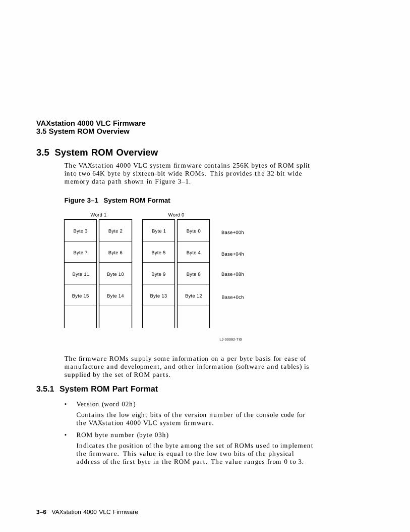
3.5 System ROM OverviewThe VAXstation 4000 VLC system firmware contains 256K bytes of ROM splitinto two 64K byte by sixteen-bit wide ROMs. This provides the 32-bit widememory data path shown in Figure 3–1.
Figure 3–1 System ROM Format
LJ-00092-TI0
Byte 3
Byte 7
Byte 11
Byte 15
Byte 2
Byte 6
Byte 10
Byte 14
Byte 1 Byte 0
Byte 5 Byte 4
Byte 9 Byte 8
Byte 13 Byte 12
Word 1 Word 0
Base+00h
Base+04h
Base+08h
Base+0ch
The firmware ROMs supply some information on a per byte basis for ease ofmanufacture and development, and other information (software and tables) issupplied by the set of ROM parts.
3.5.1 System ROM Part Format
• Version (word 02h)
Contains the low eight bits of the version number of the console code forthe VAXstation 4000 VLC system firmware.
• ROM byte number (byte 03h)
Indicates the position of the byte among the set of ROMs used to implementthe firmware. This value is equal to the low two bits of the physicaladdress of the first byte in the ROM part. The value ranges from 0 to 3.
3–6 VAXstation 4000 VLC Firmware
VAXstation 4000 VLC Firmware3.5 System ROM Overview
• Manufacturing check data (bytes 04h - 06h)
Used for a quick check of the ROM. The data are 55h, AAh, and 33h.
• ROM part length (byte 07h)
Indicates the length of the ROM part divided by the data path width inbytes.
• Checksum (last byte)
Each ROM byte contains a simple eight-bit add and rotate checksum. In a16-bit ROM the last two bytes contain a checksum: one checksum for eachbyte address in the device.
3.5.2 System ROM Set FormatThe physical addresses in the ROM set are fixed.
• 2004.000 processor restart address
The VAXstation 4000 VLC hardware begins execution at this address
At power-up
At the execution of a kernel mode halt instruction
When a break signal is received from the console device
When the HALT button is depressed
When the CPU detects a severe corruption of the operatingenvironment
• 2004.0004 SYS_TYPE
This longword is the System Type Register. The VAXstation 4000 VLCsystem type value is 0401.0102.
• 2004.0008 reserved for ROM part data
These 24 bytes are reserved for information contained in each ROM byte.
• 2004.0020 interrupt vector numbers
These eleven longwords are used by the VAXstation 4000 VLC hardware aspart of the interrupt process.
VAXstation 4000 VLC Firmware 3–7
VAXstation 4000 VLC Firmware3.5 System ROM Overview
• 2004.004C console I/O routines
There are eight I/O routines provided in the system ROM. Entry points forthese routines are located at longword intervals in this area.
• 2004.0070 reserved
Reserved so all ROM set data that follows is in the same relative position.
• 2004.0078 system console firmware revision number
This word contains the system console firmware revision number.
• 2004.007A system diagnostic firmware revision number
This word contains the system diagnostic firmware revision number.
• 2004.007C diagnostic descriptor
This longword contains the physical address of the beginning of the systemlevel diagnostic boot block. A value of zero indicates that there is nosystem level diagnostic present in the firmware ROM.
• 2004.0080 pointers to keyboard map
These two longwords point to the tables used in translating the LK401main array keycodes to character codes. The first longword contains thephysical address of the beginning of the keyboard tables. The secondlongword contains the physical address of the beginning of the keyboardmapping tables.
3–8 VAXstation 4000 VLC Firmware
VAXstation 4000 VLC Firmware3.6 Configuration Table Overview
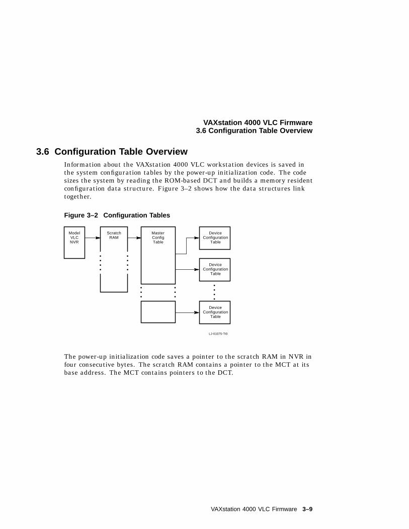
3.6 Configuration Table OverviewInformation about the VAXstation 4000 VLC workstation devices is saved inthe system configuration tables by the power-up initialization code. The codesizes the system by reading the ROM-based DCT and builds a memory residentconfiguration data structure. Figure 3–2 shows how the data structures linktogether.
Figure 3–2 Configuration Tables
LJ-01075-TI0
ModelVLCNVR
ScratchRAM
MasterConfigTable
DeviceConfiguration
Table
DeviceConfiguration
Table
DeviceConfiguration
Table
The power-up initialization code saves a pointer to the scratch RAM in NVR infour consecutive bytes. The scratch RAM contains a pointer to the MCT at itsbase address. The MCT contains pointers to the DCT.
VAXstation 4000 VLC Firmware 3–9
VAXstation 4000 VLC Firmware3.6 Configuration Table Overview
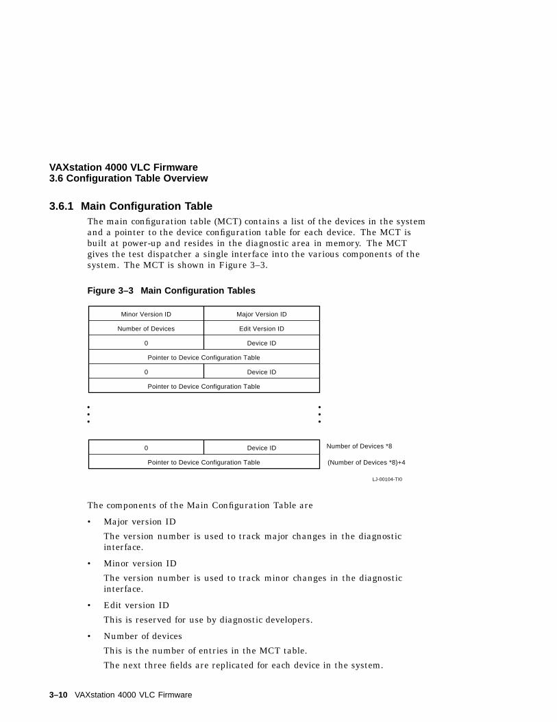
3.6.1 Main Configuration TableThe main configuration table (MCT) contains a list of the devices in the systemand a pointer to the device configuration table for each device. The MCT isbuilt at power-up and resides in the diagnostic area in memory. The MCTgives the test dispatcher a single interface into the various components of thesystem. The MCT is shown in Figure 3–3.
Figure 3–3 Main Configuration Tables
LJ-00104-TI0
Minor Version ID
Number of Devices
0
Number of Devices *8
(Number of Devices *8)+4
Major Version ID
Edit Version ID
Device ID
0 Device ID
Pointer to Device Configuration Table
Pointer to Device Configuration Table
Pointer to Device Configuration Table
0 Device ID
The components of the Main Configuration Table are
• Major version ID
The version number is used to track major changes in the diagnosticinterface.
• Minor version ID
The version number is used to track minor changes in the diagnosticinterface.
• Edit version ID
This is reserved for use by diagnostic developers.
• Number of devices
This is the number of entries in the MCT table.
The next three fields are replicated for each device in the system.
3–10 VAXstation 4000 VLC Firmware
VAXstation 4000 VLC Firmware3.6 Configuration Table Overview
• Device ID
This is the device ID number/
• Must be zero
This is reserved for future use.
• Pointer-to-Device configuration table
This points to the DCT for this particular device.
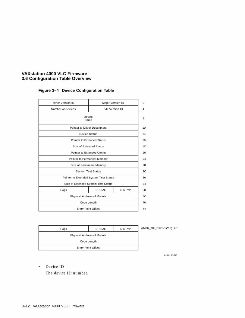
3.6.2 Device Configuration TableThere is a device configuration table (DCT) entry for each device in the system.The DCT contains extended information about the device, such as:
• Device name
• Diagnostic code location
• Header information
The test dispatcher and the system test monitor use this data to fetch theappropriate diagnostic code to execute from the ROM or to load into RAM. TheDCT is shown in Figure 3–4.
Note
In Figure 3–4 there is reference made to system test in elements 2C, 30and 34. These elements currently do not exist in the VAXstation 4000VLC, but may be added in future revisions.
The components of the Device Configuration Table are
• Major Version ID
The version number is used to track major changes in the device diagnosticroutines.
• Minor Version ID
The version number is used to track minor changes in the device diagnosticroutines.
VAXstation 4000 VLC Firmware 3–11
VAXstation 4000 VLC Firmware3.6 Configuration Table Overview
Figure 3–4 Device Configuration Table
LJ-00105-TI0
((NBR_OF_DIRS-1)*10)+2C
Entry Point Offset
Code Length
Physical Address of Module
Flags DPSIZE DIRTYP
Entry Point Offset
Code Length
Physical Address of Module
Flags DPSIZE DIRTYP
Size of Extended System Test Status
Pointer to Extended System Test Status
System Test Status
Size of Permanent Memory
Pointer to Permanent Memory
Pointer to Extended Config
Size of Extended Status
Minor Version ID
Number of Devices
Major Version ID
Edit Version ID
Pointer to Extended Status
Device Status
Pointer to Driver Descriptors
DeviceName
0
4
8
10
14
18
1C
20
24
28
2C
30
34
38
3C
40
44
• Device ID
The device ID number.
3–12 VAXstation 4000 VLC Firmware
VAXstation 4000 VLC Firmware3.6 Configuration Table Overview
• Number of directories
This is the number of directory entries for the device. A directory entrytells the user where to find a particular component of code for the device.
• Device Name
The device name is ASCII. This is used by the show configuration utilityand the system test to display information about the device.
• Pointer-to-Driver descriptors
The pointerss to the drive descriptor area associated with the device.
• Device status
This is saved from the last time that the self test was run on the device.The show configuration utility uses this field to display information aboutthe device. The device status is split into two words: the lower word is theerror field and the upper word is the FRU thought to be faulty.
• Size of extended device status
This is the length of the extended device status in bytes. The extendeddevice status can be up to 16 longwords of information. The extendedstatus displays when the user enters the SHOW ERRORS command at theconsole prompt.
• Pointer-to-Extended-Device status
This points to any extended information that is saved by the device selftest.
• Pointer-to-Extended-Configuration data
This points to extended configuration information about the device. Forexample, the SCSI self test code uses this field to save a pointer toinformation about the devices connected to the SCSI bus. The informationdisplays when the user enters the SHOW CONFIG command at the consoleprompt.
• Pointer to permanent memory allocated
This points to the permanent memory that has been allocated. The field isfilled in by the diagnostic the first time that it allocates memory.
VAXstation 4000 VLC Firmware 3–13
VAXstation 4000 VLC Firmware3.6 Configuration Table Overview
• Size of permanent memory allocated
This is the amount of permanent memory (in pages) that has beenallocated. This field is filled in by the diagnostic the first time that itallocates memory.
• System test status
Note that the VAXstation 4000 VLC system does not perform a system test.
• Pointer-to-Extended-System-Test status
Note that the VAXstation 4000 VLC does not perform a system test.
• Size of Extended System Test Status
Note that the VAXstation 4000 VLC does not perform a system test.
• Directory type
Contains the type of directory entry that the previous elements refer to.Table 3–1 lists the directory type.
Table 3–1 Directory Type Definitions
Definition Meaning
1 Self test directory entry
2
3 Utility directory entry
4 Console routine directory entry
5 Unjam routine directory entry
6 Diagnostic driver directory entry
• Data path size
This contains the data path size of the ROM in which the piece of coderesides. The path size is listed in Table 3–2.
Table 3–2 Data Path Size Definitions
Definition Meaning
1 ROM width is one byte wide
2 ROM width is two bytes wide
4 ROM width is four bytes wide
• Flags
3–14 VAXstation 4000 VLC Firmware
VAXstation 4000 VLC Firmware3.6 Configuration Table Overview
This contains flag data associated with the particular device routine.Table 3–3 lists the flag definitions.
Table 3–3 Flag Definitions
Definition Meaning
Bit 15=1 Code must be loaded into RAM at power-up and memory marked asunavailable to the operating system.
Bit 14=1 Code must be loaded into RAM to execute. The memory is releasedafter execution is complete.
Bit 13=1 Code has been loaded into RAM at power-up and memory marked asunavailable to the operating system.
Bit 0=1 Code uses shared diagnostic driver.
• Length of code
This contains the length of code in bytes.
• Physical address of the module
This contains the physical address for this particular component of thecode.
• Entry point offset
This contains the offset from the beginning of the code to where the entrypoint is.
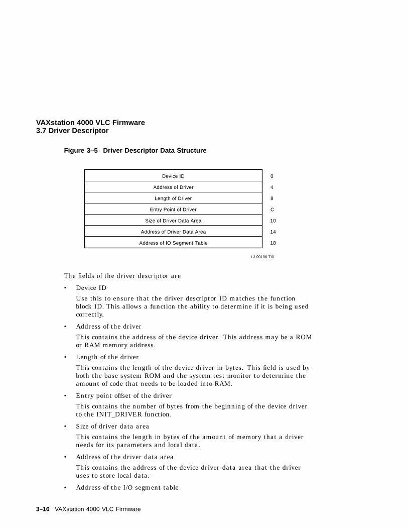
3.7 Driver DescriptorAny device that provides a shared port driver or shared class driver mustprovide a descriptor that tells the base system firmware, system test monitor,and any other piece of software specific information about the drive. A driverdescriptor has the format shown in Figure 3–5.
VAXstation 4000 VLC Firmware 3–15
VAXstation 4000 VLC Firmware3.7 Driver Descriptor
Figure 3–5 Driver Descriptor Data Structure
LJ-00106-TI0
Address of IO Segment Table
Address of Driver Data Area
Size of Driver Data Area
Entry Point of Driver
Length of Driver
Address of Driver
Device ID 0
4
8
C
10
14
18
The fields of the driver descriptor are
• Device ID
Use this to ensure that the driver descriptor ID matches the functionblock ID. This allows a function the ability to determine if it is being usedcorrectly.
• Address of the driver
This contains the address of the device driver. This address may be a ROMor RAM memory address.
• Length of the driver
This contains the length of the device driver in bytes. This field is used byboth the base system ROM and the system test monitor to determine theamount of code that needs to be loaded into RAM.
• Entry point offset of the driver
This contains the number of bytes from the beginning of the device driverto the INIT_DRIVER function.
• Size of driver data area
This contains the length in bytes of the amount of memory that a driverneeds for its parameters and local data.
• Address of the driver data area
This contains the address of the device driver data area that the driveruses to store local data.
• Address of the I/O segment table
3–16 VAXstation 4000 VLC Firmware
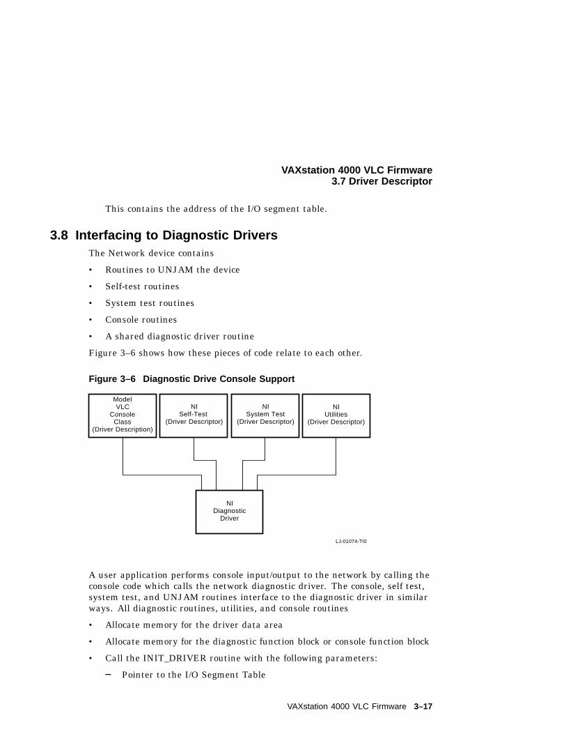
VAXstation 4000 VLC Firmware3.7 Driver Descriptor
This contains the address of the I/O segment table.
3.8 Interfacing to Diagnostic DriversThe Network device contains
• Routines to UNJAM the device
• Self-test routines
• System test routines
• Console routines
• A shared diagnostic driver routine
Figure 3–6 shows how these pieces of code relate to each other.
Figure 3–6 Diagnostic Drive Console Support
LJ-01074-TI0
ModelVLC
ConsoleClass
(Driver Description)
NISelf-Test
(Driver Descriptor)
NISystem Test
(Driver Descriptor)
NIDiagnostic
Driver
NIUtilities
(Driver Descriptor)
A user application performs console input/output to the network by calling theconsole code which calls the network diagnostic driver. The console, self test,system test, and UNJAM routines interface to the diagnostic driver in similarways. All diagnostic routines, utilities, and console routines
• Allocate memory for the driver data area
• Allocate memory for the diagnostic function block or console function block
• Call the INIT_DRIVER routine with the following parameters:
Pointer to the I/O Segment Table
VAXstation 4000 VLC Firmware 3–17
VAXstation 4000 VLC Firmware3.8 Interfacing to Diagnostic Drivers
Pointer to the Driver Data Area
Pointer to the Driver Function Block or Console Function Block
Pointer to the Shared Console Interface Area; or add zero if this is nota console driver
As many as two additional device specific parameters
3–18 VAXstation 4000 VLC Firmware
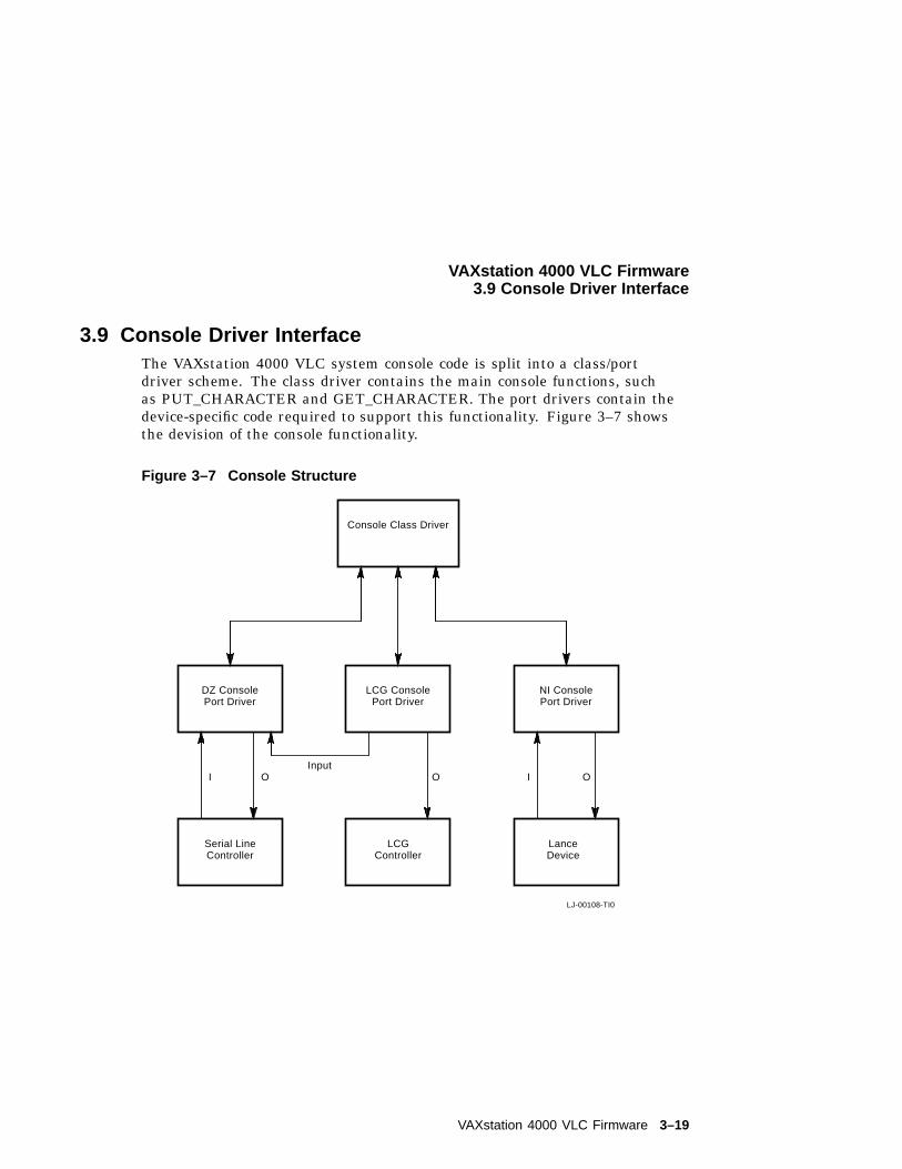
VAXstation 4000 VLC Firmware3.9 Console Driver Interface
3.9 Console Driver InterfaceThe VAXstation 4000 VLC system console code is split into a class/portdriver scheme. The class driver contains the main console functions, suchas PUT_CHARACTER and GET_CHARACTER. The port drivers contain thedevice-specific code required to support this functionality. Figure 3–7 showsthe devision of the console functionality.
Figure 3–7 Console Structure
LJ-00108-TI0
Console Class Driver
DZ ConsolePort Driver
LCG ConsolePort Driver
NI ConsolePort Driver
Serial LineController
LCGController
LanceDevice
InputI O O I O
VAXstation 4000 VLC Firmware 3–19
VAXstation 4000 VLC Firmware3.9 Console Driver Interface
The console device can require either one or two channels to perform I/O withthe console device. If the console device is a graphics terminal with an LK401keyboard, the console program interfaces with the serial line device driverfor ASCII input and with the graphics device driver for output. If the consoledevice is a terminal connected to a serial line, the console responds to the serialline driver for both input and output.
The console class driver contains the generic routines that interface tothe console and use applications to perform terminal input and outputtransactions. The console class driver interfaces with the port driver dependingon the current console device.
If the console port driver does not support PUT_CHARACTER or GET_CHARACTER functionality, it must interface with the appropriate port driverto perform the needed function.
3.9.1 Shared Console Interface AreaThe shared console interface area (SCIA) consists of a console class driverdescriptor and three port driver descriptors. The port driver descriptors canbe associated with a DZ port driver, a graphics output driver, and a networkdriver.
The SCIA provides an interface to the console terminal that isolates theimplementation specifics of accessing the console terminal. It is designed toallow the console drivers to run in both virtual and physical mode.
The SCIA is set up by the power-up initialization code. After it is set up, thesoftware can use this area to interface with the console class driver routine.The shared console performs the following:
• Raw character I/O to the console terminal
• Higher level of I/O functions that handle XON/XOFF flow, ASCII bellcharacter, and LK401 keyboard translation are handled by the DZ driver.
• Data structures that allow the system software to map all console code andI/O space references into virtual memory as needed
The SCIA data structure is shown in Figure 3–8.
3–20 VAXstation 4000 VLC Firmware
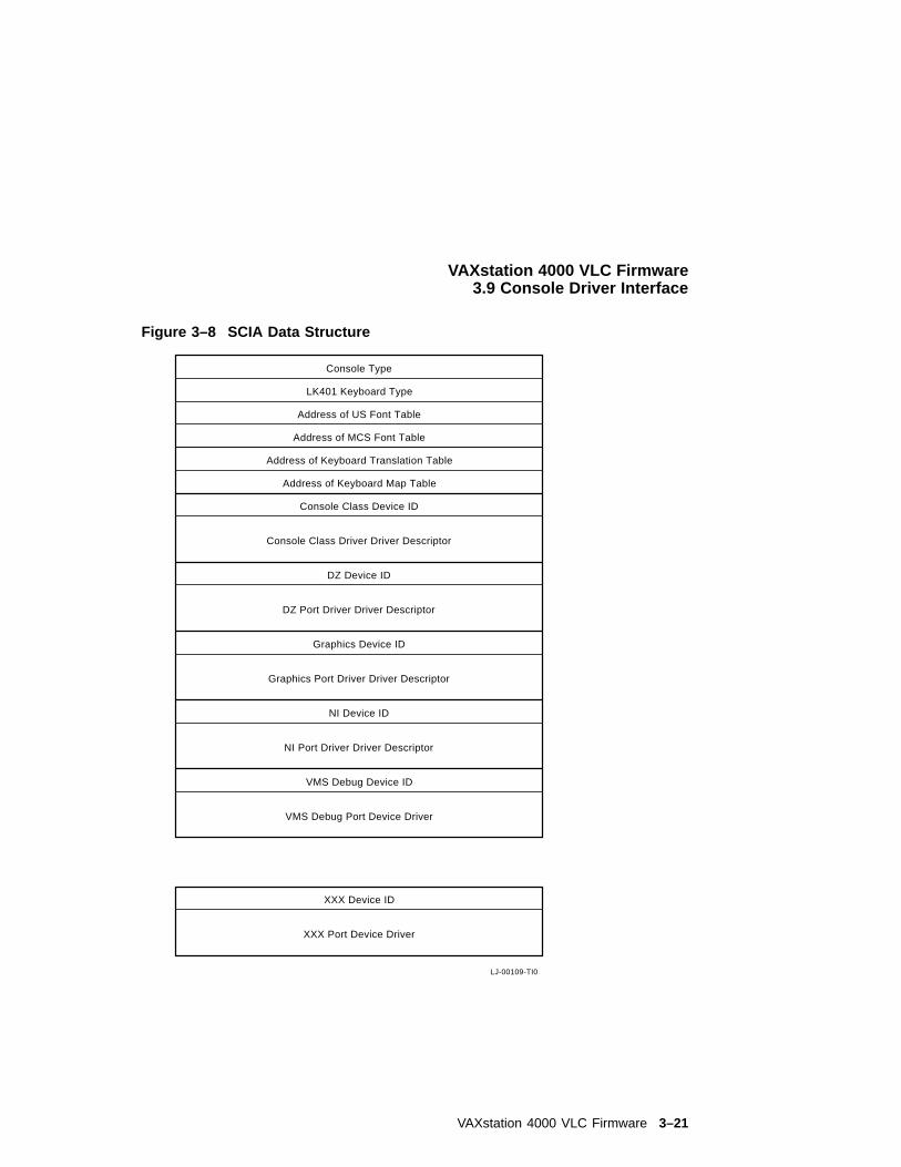
VAXstation 4000 VLC Firmware3.9 Console Driver Interface
Figure 3–8 SCIA Data Structure
LJ-00109-TI0
Console Type
LK401 Keyboard Type
Address of US Font Table
Address of MCS Font Table
Address of Keyboard Translation Table
Address of Keyboard Map Table
Console Class Device ID
Console Class Driver Driver Descriptor
DZ Device ID
DZ Port Driver Driver Descriptor
NI Device ID
NI Port Driver Driver Descriptor
VMS Debug Device ID
VMS Debug Port Device Driver
XXX Device ID
XXX Port Device Driver
Graphics Device ID
Graphics Port Driver Driver Descriptor
VAXstation 4000 VLC Firmware 3–21
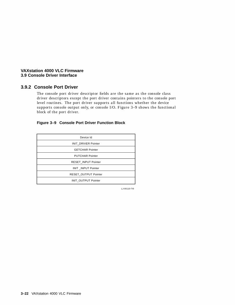
VAXstation 4000 VLC Firmware3.9 Console Driver Interface
3.9.2 Console Port DriverThe console port driver descriptor fields are the same as the console classdriver descriptors except the port driver contains pointers to the console portlevel routines. The port driver supports all functions whether the devicesupports console output only, or console I/O. Figure 3–9 shows the functionalblock of the port driver.
Figure 3–9 Console Port Driver Function Block
LJ-00110-TI0
Device Id
INIT_DRIVER Pointer
GETCHAR Pointer
PUTCHAR Pointer
RESET_INPUT Pointer
INIT _INPUT Pointer
RESET_OUTPUT Pointer
INIT_OUTPUT Pointer
3–22 VAXstation 4000 VLC Firmware
4Diagnostic Testing
This chapter describes the diagnostic testa, test commands, and error codesprovided with the VAXstation 4000 VLC system.
4.1 Diagnostic TestingSystem troubleshooting involves several types of tests:
• Power-Up Self Test
This test includes initialization and power-up testing of all devices.
• Extended Self Test
This test executes when a user runs a self-test diagnostic by entering aTEST command at the console prompt.
• Utilities Test
This test provides tools to test and align a video monitor and initialize diskdrives.
Diagnostic Testing 4–1
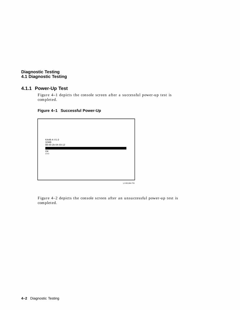
Diagnostic Testing4.1 Diagnostic Testing
4.1.1 Power-Up TestFigure 4–1 depicts the console screen after a successful power-up test iscompleted.
Figure 4–1 Successful Power-Up
KA48-A V1.032MB08-00-2b-04-03-12
LJ-001384-TI0
>>>OK
Figure 4–2 depicts the console screen after an unsuccessful power-up test iscompleted.
4–2 Diagnostic Testing
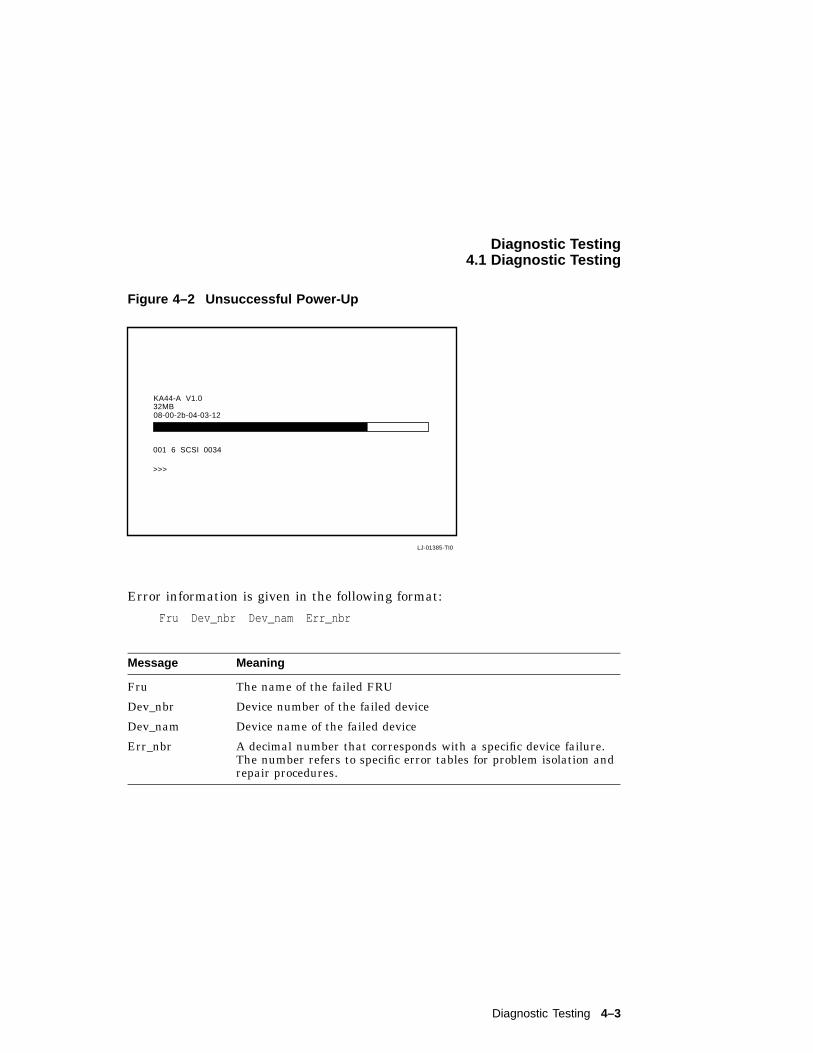
Diagnostic Testing4.1 Diagnostic Testing
Figure 4–2 Unsuccessful Power-Up
001 6 SCSI 0034
32MB08-00-2b-04-03-12
LJ-01385-TI0
>>>
KA44-A V1.0
Error information is given in the following format:
Fru Dev_nbr Dev_nam Err_nbr
Message Meaning
Fru The name of the failed FRU
Dev_nbr Device number of the failed device
Dev_nam Device name of the failed device
Err_nbr A decimal number that corresponds with a specific device failure.The number refers to specific error tables for problem isolation andrepair procedures.
Diagnostic Testing 4–3
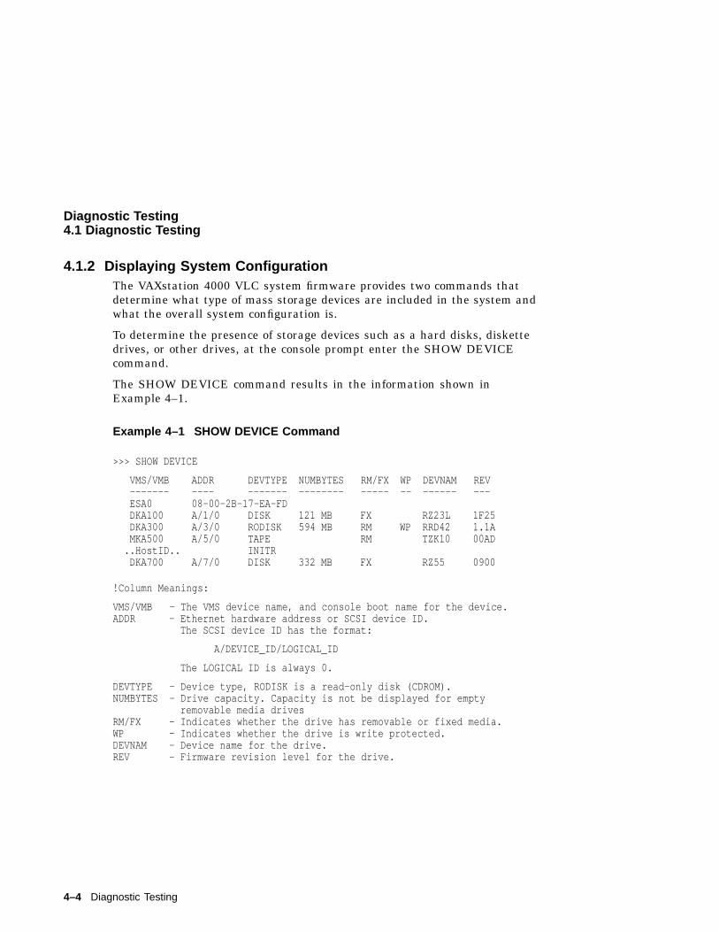
Diagnostic Testing4.1 Diagnostic Testing
4.1.2 Displaying System ConfigurationThe VAXstation 4000 VLC system firmware provides two commands thatdetermine what type of mass storage devices are included in the system andwhat the overall system configuration is.
To determine the presence of storage devices such as a hard disks, diskettedrives, or other drives, at the console prompt enter the SHOW DEVICEcommand.
The SHOW DEVICE command results in the information shown inExample 4–1.
Example 4–1 SHOW DEVICE Command
>>> SHOW DEVICE
VMS/VMB ADDR DEVTYPE NUMBYTES RM/FX WP DEVNAM REV------- ---- ------- -------- ----- -- ------ ---ESA0 08-00-2B-17-EA-FDDKA100 A/1/0 DISK 121 MB FX RZ23L 1F25DKA300 A/3/0 RODISK 594 MB RM WP RRD42 1.1AMKA500 A/5/0 TAPE RM TZK10 00AD
..HostID.. INITRDKA700 A/7/0 DISK 332 MB FX RZ55 0900
!Column Meanings:
VMS/VMB - The VMS device name, and console boot name for the device.ADDR - Ethernet hardware address or SCSI device ID.
The SCSI device ID has the format:
A/DEVICE_ID/LOGICAL_ID
The LOGICAL ID is always 0.
DEVTYPE - Device type, RODISK is a read-only disk (CDROM).NUMBYTES - Drive capacity. Capacity is not be displayed for empty
removable media drivesRM/FX - Indicates whether the drive has removable or fixed media.WP - Indicates whether the drive is write protected.DEVNAM - Device name for the drive.REV - Firmware revision level for the drive.
4–4 Diagnostic Testing
Diagnostic Testing4.1 Diagnostic Testing
To determine the presence of devices other than internal storage devices andto determine the quantity of memory in the system, enter the SHOW CONFIGcommand at the console prompt.
The system presents a configuration table similar to Example 4–2.
Example 4–2 Sample Show Config Display
Diagnostic Testing 4–5
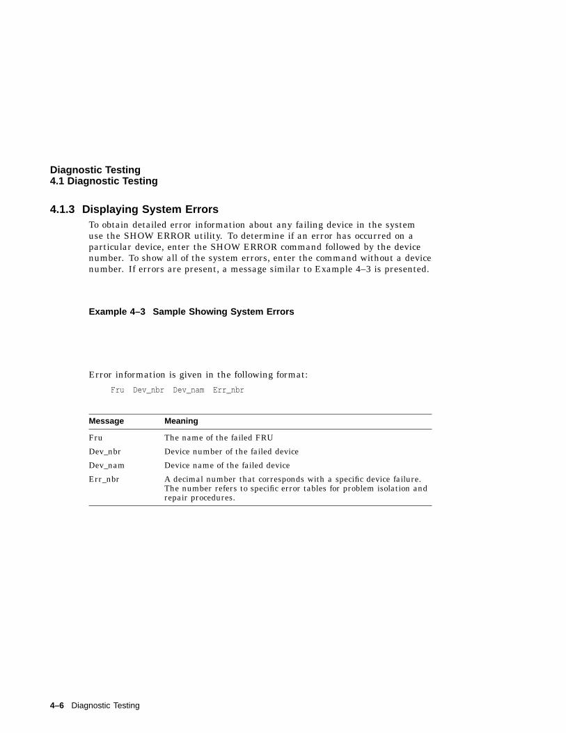
Diagnostic Testing4.1 Diagnostic Testing
4.1.3 Displaying System ErrorsTo obtain detailed error information about any failing device in the systemuse the SHOW ERROR utility. To determine if an error has occurred on aparticular device, enter the SHOW ERROR command followed by the devicenumber. To show all of the system errors, enter the command without a devicenumber. If errors are present, a message similar to Example 4–3 is presented.
Example 4–3 Sample Showing System Errors
Error information is given in the following format:
Fru Dev_nbr Dev_nam Err_nbr
Message Meaning
Fru The name of the failed FRU
Dev_nbr Device number of the failed device
Dev_nam Device name of the failed device
Err_nbr A decimal number that corresponds with a specific device failure.The number refers to specific error tables for problem isolation andrepair procedures.
4–6 Diagnostic Testing
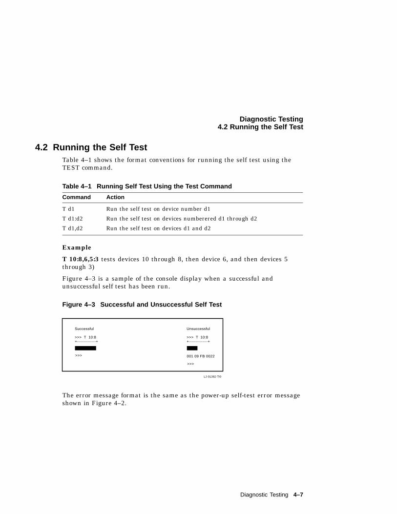
Diagnostic Testing4.2 Running the Self Test
4.2 Running the Self TestTable 4–1 shows the format conventions for running the self test using theTEST command.
Table 4–1 Running Self Test Using the Test Command
Command Action
T d1 Run the self test on device number d1
T d1:d2 Run the self test on devices numberered d1 through d2
T d1,d2 Run the self test on devices d1 and d2
Example
T 10:8,6,5:3 tests devices 10 through 8, then device 6, and then devices 5through 3)
Figure 4–3 is a sample of the console display when a successful andunsuccessful self test has been run.
Figure 4–3 Successful and Unsuccessful Self Test
LJ-01382-TI0
>>>
Successful Unsuccessful
001 09 FB 0022
>>> T 10:8+--------------+
>>> T 10:8+--------------+
>>>
The error message format is the same as the power-up self-test error messageshown in Figure 4–2.
Diagnostic Testing 4–7
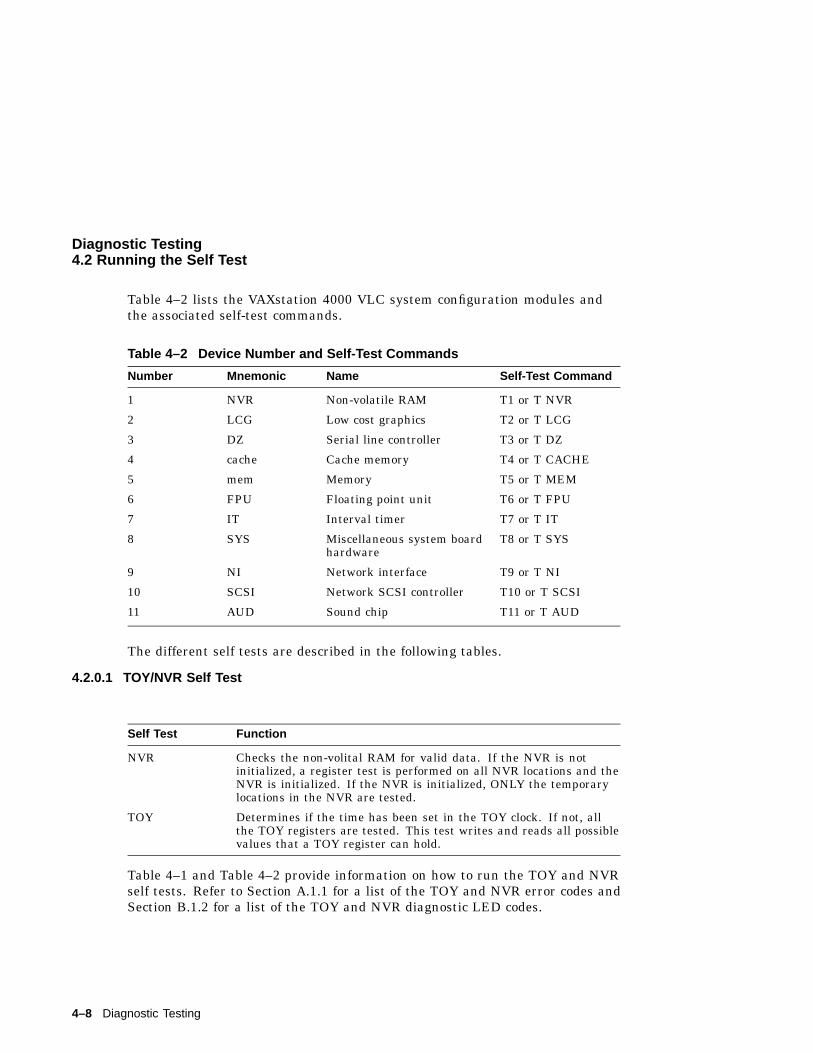
Diagnostic Testing4.2 Running the Self Test
Table 4–2 lists the VAXstation 4000 VLC system configuration modules andthe associated self-test commands.
Table 4–2 Device Number and Self-Test Commands
Number Mnemonic Name Self-Test Command
1 NVR Non-volatile RAM T1 or T NVR
2 LCG Low cost graphics T2 or T LCG
3 DZ Serial line controller T3 or T DZ
4 cache Cache memory T4 or T CACHE
5 mem Memory T5 or T MEM
6 FPU Floating point unit T6 or T FPU
7 IT Interval timer T7 or T IT
8 SYS Miscellaneous system boardhardware
T8 or T SYS
9 NI Network interface T9 or T NI
10 SCSI Network SCSI controller T10 or T SCSI
11 AUD Sound chip T11 or T AUD
The different self tests are described in the following tables.
4.2.0.1 TOY/NVR Self Test
Self Test Function
NVR Checks the non-volital RAM for valid data. If the NVR is notinitialized, a register test is performed on all NVR locations and theNVR is initialized. If the NVR is initialized, ONLY the temporarylocations in the NVR are tested.
TOY Determines if the time has been set in the TOY clock. If not, allthe TOY registers are tested. This test writes and reads all possiblevalues that a TOY register can hold.
Table 4–1 and Table 4–2 provide information on how to run the TOY and NVRself tests. Refer to Section A.1.1 for a list of the TOY and NVR error codes andSection B.1.2 for a list of the TOY and NVR diagnostic LED codes.
4–8 Diagnostic Testing
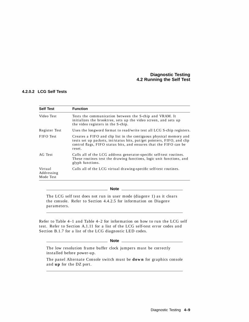
Diagnostic Testing4.2 Running the Self Test
4.2.0.2 LCG Self Tests
Self Test Function
Video Test Tests the communication between the S-chip and VRAM. Itinitializes the brooktree, sets up the video screen, and sets upthe video registers in the S-chip.
Register Test Uses the longword format to read/write test all LCG S-chip registers.
FIFO Test Creates a FIFO and clip list in the contiguous physical memory andtests set up packets, int/status bits, put/get pointers, FIFO, and clipcontrol flags, FIFO status bits, and ensures that the FIFO can bereset.
AG Test Calls all of the LCG address generator-specific self-test routines.These routines test the drawing functions, logic unit functions, andglyph functions.
VirtualAddressingMode Test
Calls all of the LCG virtual drawing-specific self-test routines.
Note
The LCG self test does not run in user mode (diagenv 1) as it clearsthe console. Refer to Section 4.4.2.5 for information on Diagenvparameters.
Refer to Table 4–1 and Table 4–2 for information on how to run the LCG selftest. Refer to Section A.1.11 for a list of the LCG self-test error codes andSection B.1.7 for a list of the LCG diagnostic LED codes.
Note
The low resolution frame buffer clock jumpers must be correctlyinstalled before power-up.
The panel Alternate Console switch must be down for graphics consoleand up for the DZ port.
Diagnostic Testing 4–9
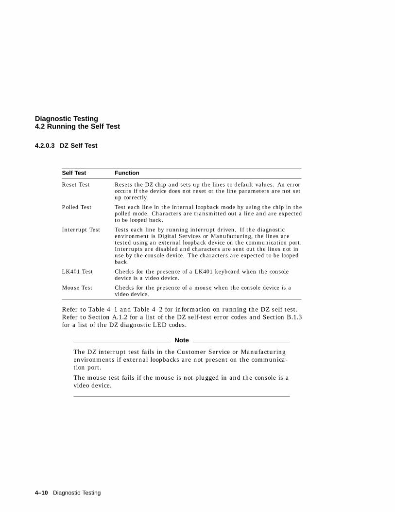
Diagnostic Testing4.2 Running the Self Test
4.2.0.3 DZ Self Test
Self Test Function
Reset Test Resets the DZ chip and sets up the lines to default values. An erroroccurs if the device does not reset or the line parameters are not setup correctly.
Polled Test Test each line in the internal loopback mode by using the chip in thepolled mode. Characters are transmitted out a line and are expectedto be looped back.
Interrupt Test Tests each line by running interrupt driven. If the diagnosticenvironment is Digital Services or Manufacturing, the lines aretested using an external loopback device on the communication port.Interrupts are disabled and characters are sent out the lines not inuse by the console device. The characters are expected to be loopedback.
LK401 Test Checks for the presence of a LK401 keyboard when the consoledevice is a video device.
Mouse Test Checks for the presence of a mouse when the console device is avideo device.
Refer to Table 4–1 and Table 4–2 for information on running the DZ self test.Refer to Section A.1.2 for a list of the DZ self-test error codes and Section B.1.3for a list of the DZ diagnostic LED codes.
Note
The DZ interrupt test fails in the Customer Service or Manufacturingenvironments if external loopbacks are not present on the communica-tion port.
The mouse test fails if the mouse is not plugged in and the console is avideo device.
4–10 Diagnostic Testing
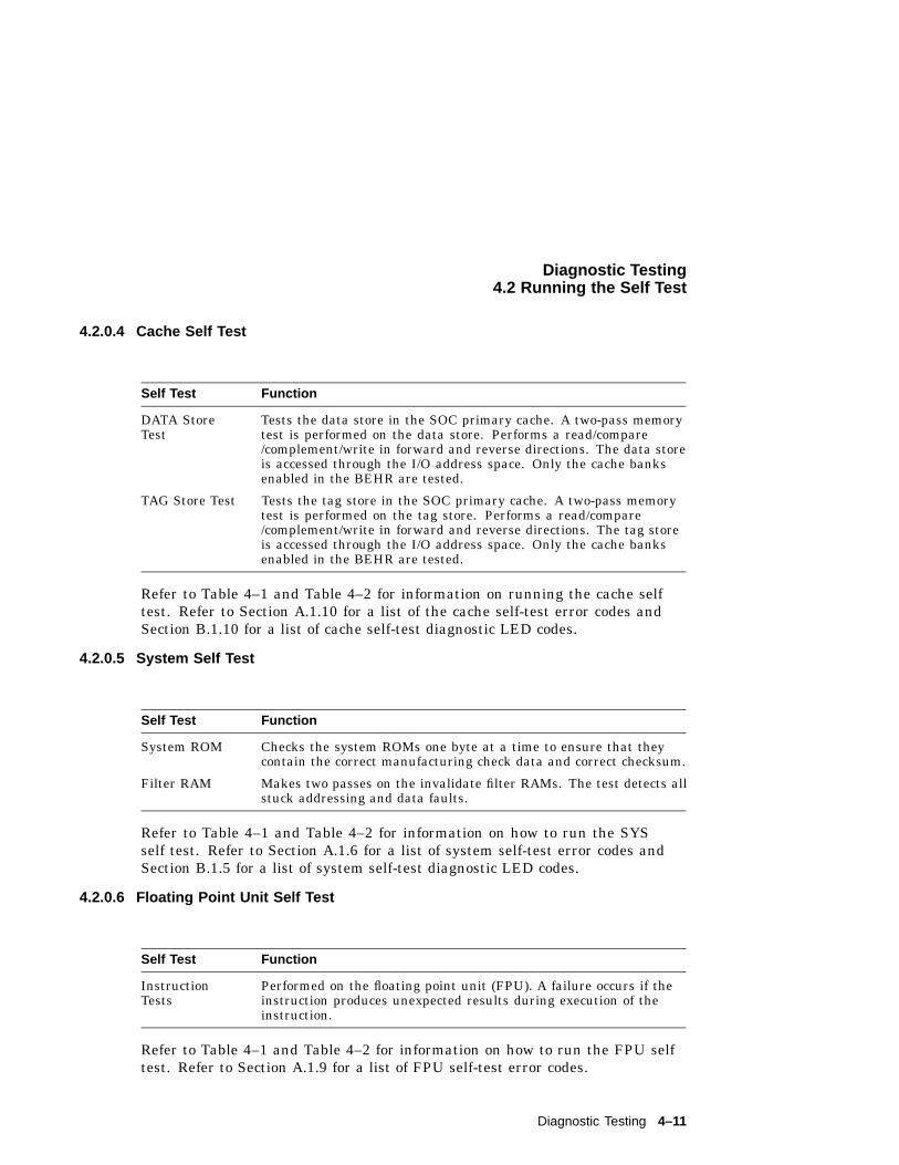
Diagnostic Testing4.2 Running the Self Test
4.2.0.4 Cache Self Test
Self Test Function
DATA StoreTest
Tests the data store in the SOC primary cache. A two-pass memorytest is performed on the data store. Performs a read/compare/complement/write in forward and reverse directions. The data storeis accessed through the I/O address space. Only the cache banksenabled in the BEHR are tested.
TAG Store Test Tests the tag store in the SOC primary cache. A two-pass memorytest is performed on the tag store. Performs a read/compare/complement/write in forward and reverse directions. The tag storeis accessed through the I/O address space. Only the cache banksenabled in the BEHR are tested.
Refer to Table 4–1 and Table 4–2 for information on running the cache selftest. Refer to Section A.1.10 for a list of the cache self-test error codes andSection B.1.10 for a list of cache self-test diagnostic LED codes.
4.2.0.5 System Self Test
Self Test Function
System ROM Checks the system ROMs one byte at a time to ensure that theycontain the correct manufacturing check data and correct checksum.
Filter RAM Makes two passes on the invalidate filter RAMs. The test detects allstuck addressing and data faults.
Refer to Table 4–1 and Table 4–2 for information on how to run the SYSself test. Refer to Section A.1.6 for a list of system self-test error codes andSection B.1.5 for a list of system self-test diagnostic LED codes.
4.2.0.6 Floating Point Unit Self Test
Self Test Function
InstructionTests
Performed on the floating point unit (FPU). A failure occurs if theinstruction produces unexpected results during execution of theinstruction.
Refer to Table 4–1 and Table 4–2 for information on how to run the FPU selftest. Refer to Section A.1.9 for a list of FPU self-test error codes.
Diagnostic Testing 4–11
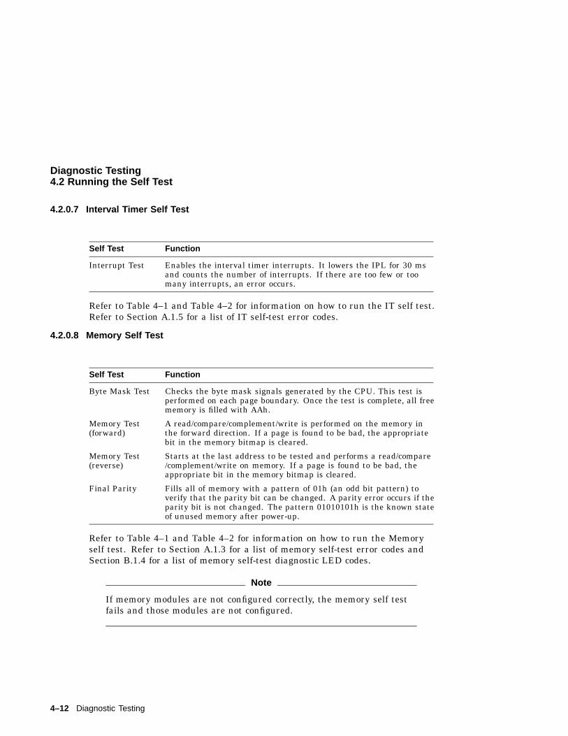
Diagnostic Testing4.2 Running the Self Test
4.2.0.7 Interval Timer Self Test
Self Test Function
Interrupt Test Enables the interval timer interrupts. It lowers the IPL for 30 msand counts the number of interrupts. If there are too few or toomany interrupts, an error occurs.
Refer to Table 4–1 and Table 4–2 for information on how to run the IT self test.Refer to Section A.1.5 for a list of IT self-test error codes.
4.2.0.8 Memory Self Test
Self Test Function
Byte Mask Test Checks the byte mask signals generated by the CPU. This test isperformed on each page boundary. Once the test is complete, all freememory is filled with AAh.
Memory Test(forward)
A read/compare/complement/write is performed on the memory inthe forward direction. If a page is found to be bad, the appropriatebit in the memory bitmap is cleared.
Memory Test(reverse)
Starts at the last address to be tested and performs a read/compare/complement/write on memory. If a page is found to be bad, theappropriate bit in the memory bitmap is cleared.
Final Parity Fills all of memory with a pattern of 01h (an odd bit pattern) toverify that the parity bit can be changed. A parity error occurs if theparity bit is not changed. The pattern 01010101h is the known stateof unused memory after power-up.
Refer to Table 4–1 and Table 4–2 for information on how to run the Memoryself test. Refer to Section A.1.3 for a list of memory self-test error codes andSection B.1.4 for a list of memory self-test diagnostic LED codes.
Note
If memory modules are not configured correctly, the memory self testfails and those modules are not configured.
4–12 Diagnostic Testing
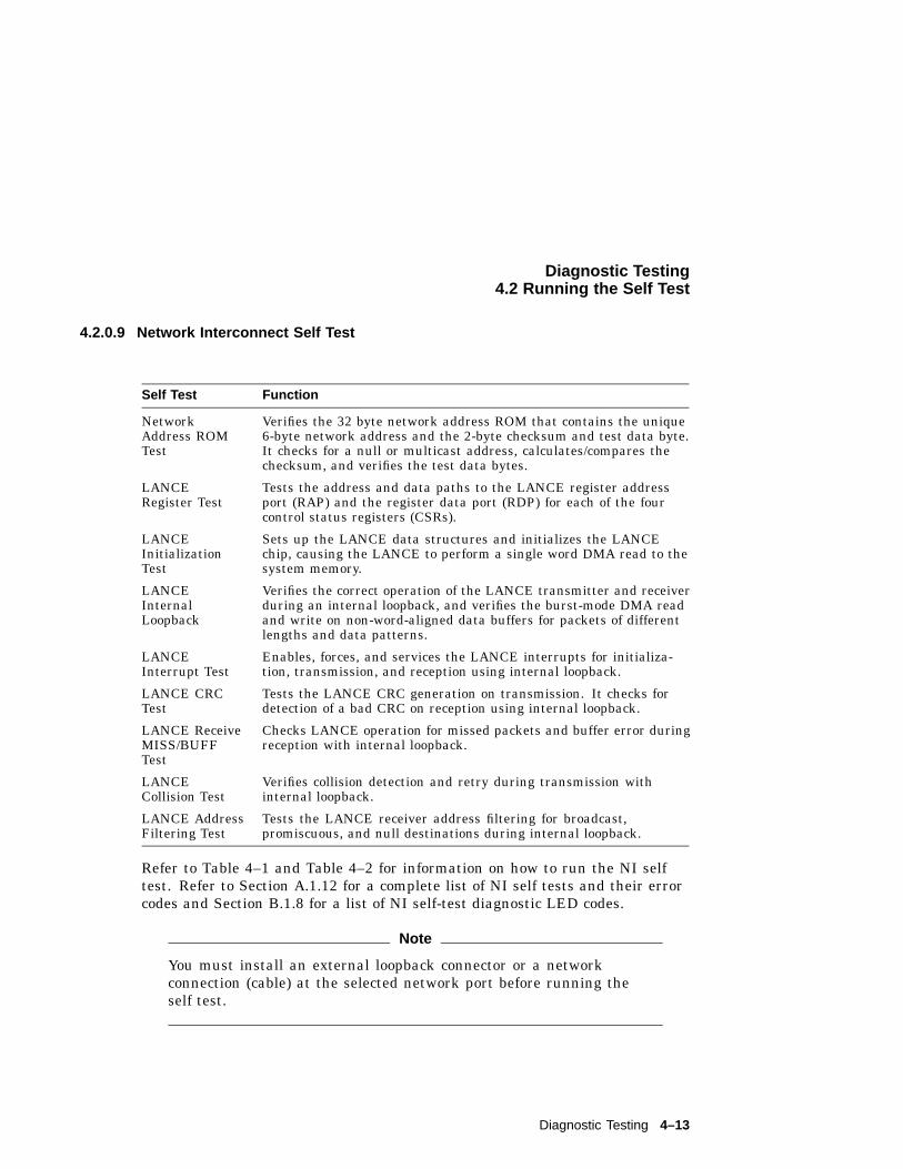
Diagnostic Testing4.2 Running the Self Test
4.2.0.9 Network Interconnect Self Test
Self Test Function
NetworkAddress ROMTest
Verifies the 32 byte network address ROM that contains the unique6-byte network address and the 2-byte checksum and test data byte.It checks for a null or multicast address, calculates/compares thechecksum, and verifies the test data bytes.
LANCERegister Test
Tests the address and data paths to the LANCE register addressport (RAP) and the register data port (RDP) for each of the fourcontrol status registers (CSRs).
LANCEInitializationTest
Sets up the LANCE data structures and initializes the LANCEchip, causing the LANCE to perform a single word DMA read to thesystem memory.
LANCEInternalLoopback
Verifies the correct operation of the LANCE transmitter and receiverduring an internal loopback, and verifies the burst-mode DMA readand write on non-word-aligned data buffers for packets of differentlengths and data patterns.
LANCEInterrupt Test
Enables, forces, and services the LANCE interrupts for initializa-tion, transmission, and reception using internal loopback.
LANCE CRCTest
Tests the LANCE CRC generation on transmission. It checks fordetection of a bad CRC on reception using internal loopback.
LANCE ReceiveMISS/BUFFTest
Checks LANCE operation for missed packets and buffer error duringreception with internal loopback.
LANCECollision Test
Verifies collision detection and retry during transmission withinternal loopback.
LANCE AddressFiltering Test
Tests the LANCE receiver address filtering for broadcast,promiscuous, and null destinations during internal loopback.
Refer to Table 4–1 and Table 4–2 for information on how to run the NI selftest. Refer to Section A.1.12 for a complete list of NI self tests and their errorcodes and Section B.1.8 for a list of NI self-test diagnostic LED codes.
Note
You must install an external loopback connector or a networkconnection (cable) at the selected network port before running theself test.
Diagnostic Testing 4–13
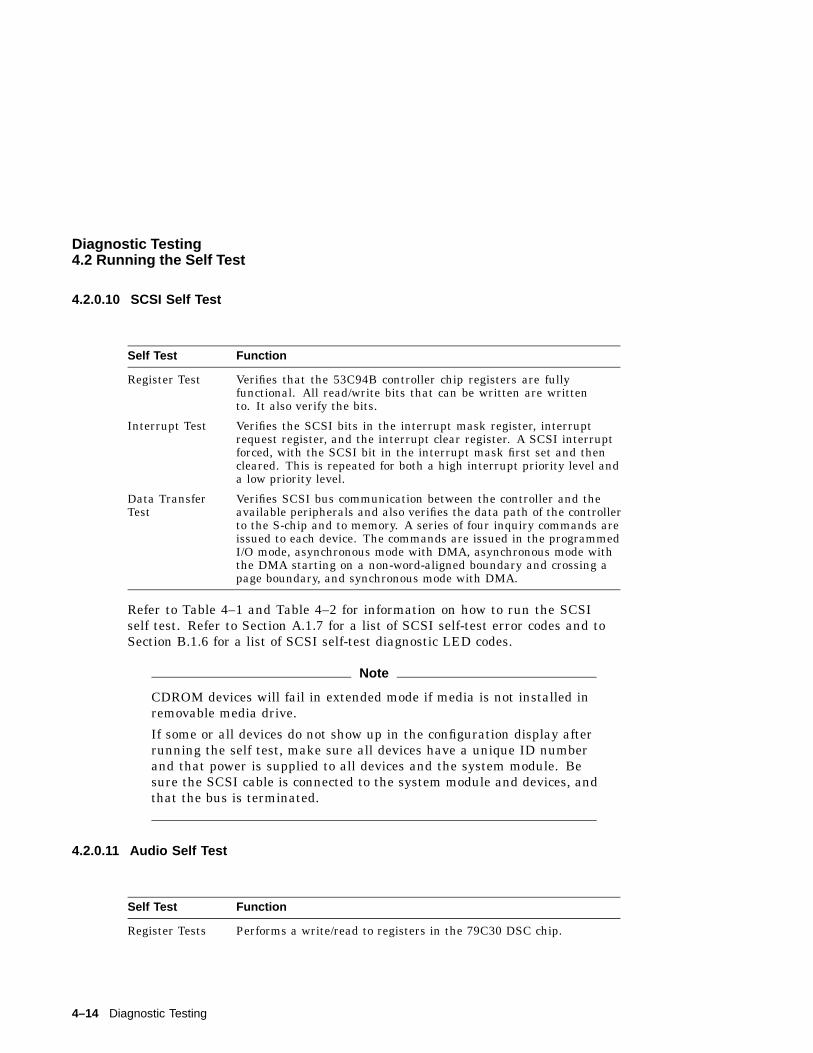
Diagnostic Testing4.2 Running the Self Test
4.2.0.10 SCSI Self Test
Self Test Function
Register Test Verifies that the 53C94B controller chip registers are fullyfunctional. All read/write bits that can be written are writtento. It also verify the bits.
Interrupt Test Verifies the SCSI bits in the interrupt mask register, interruptrequest register, and the interrupt clear register. A SCSI interruptforced, with the SCSI bit in the interrupt mask first set and thencleared. This is repeated for both a high interrupt priority level anda low priority level.
Data TransferTest
Verifies SCSI bus communication between the controller and theavailable peripherals and also verifies the data path of the controllerto the S-chip and to memory. A series of four inquiry commands areissued to each device. The commands are issued in the programmedI/O mode, asynchronous mode with DMA, asynchronous mode withthe DMA starting on a non-word-aligned boundary and crossing apage boundary, and synchronous mode with DMA.
Refer to Table 4–1 and Table 4–2 for information on how to run the SCSIself test. Refer to Section A.1.7 for a list of SCSI self-test error codes and toSection B.1.6 for a list of SCSI self-test diagnostic LED codes.
Note
CDROM devices will fail in extended mode if media is not installed inremovable media drive.
If some or all devices do not show up in the configuration display afterrunning the self test, make sure all devices have a unique ID numberand that power is supplied to all devices and the system module. Besure the SCSI cable is connected to the system module and devices, andthat the bus is terminated.
4.2.0.11 Audio Self Test
Self Test Function
Register Tests Performs a write/read to registers in the 79C30 DSC chip.
4–14 Diagnostic Testing
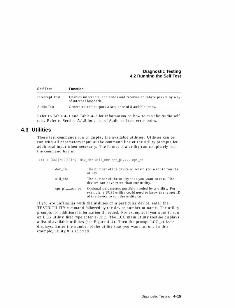
Diagnostic Testing4.2 Running the Self Test
Self Test Function
Interrupt Test Enables interrupts, and sends and receives an 8-byte packet by wayof internal loopback.
Audio Test Generates and outputs a sequence of 8 audible tones.
Refer to Table 4–1 and Table 4–2 for information on how to run the Audio selftest. Refer to Section A.1.8 for a list of Audio self-test error codes.
4.3 UtilitiesThese test commands run or display the available utilities. Utilities can berun with all parameters input at the command line or the utility prompts foradditional input when necessary. The format of a utility run completely fromthe command line is
>>> T [EST]/UT[ility] dev_nbr util_nbr opt_p1,...,opt_pn
dev_nbr The number of the device on which you want to run theutility
util_nbr The number of the utility that you want to run. Thedevices can have more than one utility.
opt_p1,...,opt_pn Optional parameters possibly needed by a utility. Forexample, a SCSI utility could need to know the target IDof the device to run the utility on.
If you are unfamiliar with the utilities on a particular device, enter theTEST/UTILITY command followed by the device number or name. The utilityprompts for additional information if needed. For example, if you want to runan LCG utility, first type enter T/UT 2 . The LCG main utility routine displaysa list of available utilities (see Figure 4–4). Then the prompt LCG_util>>>displays. Enter the number of the utility that you want to run. In thisexample, utility 8 is selected.
Diagnostic Testing 4–15
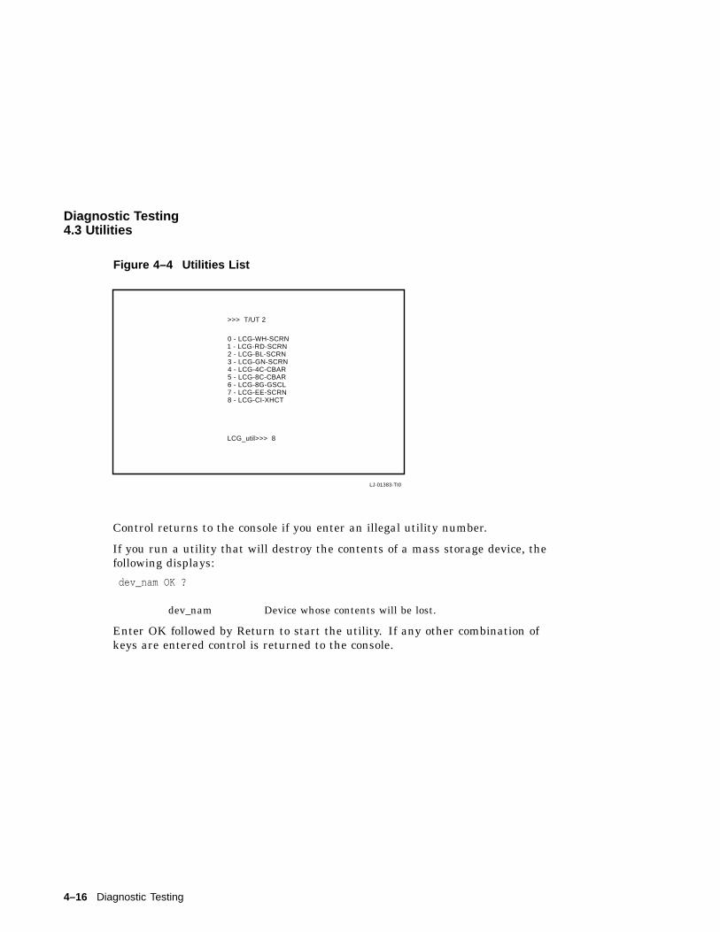
Diagnostic Testing4.3 Utilities
Figure 4–4 Utilities List
LJ-01383-TI0
>>> T/UT 2
0 - LCG-WH-SCRN1 - LCG-RD-SCRN2 - LCG-BL-SCRN3 - LCG-GN-SCRN4 - LCG-4C-CBAR5 - LCG-8C-CBAR6 - LCG-8G-GSCL7 - LCG-EE-SCRN8 - LCG-CI-XHCT
LCG_util>>> 8
Control returns to the console if you enter an illegal utility number.
If you run a utility that will destroy the contents of a mass storage device, thefollowing displays:
dev_nam OK ?
dev_nam Device whose contents will be lost.
Enter OK followed by Return to start the utility. If any other combination ofkeys are entered control is returned to the console.
4–16 Diagnostic Testing
Diagnostic Testing4.4 System Console
4.4 System ConsoleThis section describes the standard console commands for the VAXstation 4000VLC system. The console commands are divided into three functional groups.
• SET/SHOW Commands
Use these commands to set or examine system parameters andconfiguration.
• Memory Commands
These include the DEPOSIT, EXAMINE, FIND, MOVE, and SEARCHcommands.
• Processor Control Commands
These commands are BOOT, CONTINUE, HALT, INIT, START, andUNJAM.
• Miscellaneous Commands
HELP or ?, LOGIN, and REPEAT.
Diagnostic Testing 4–17
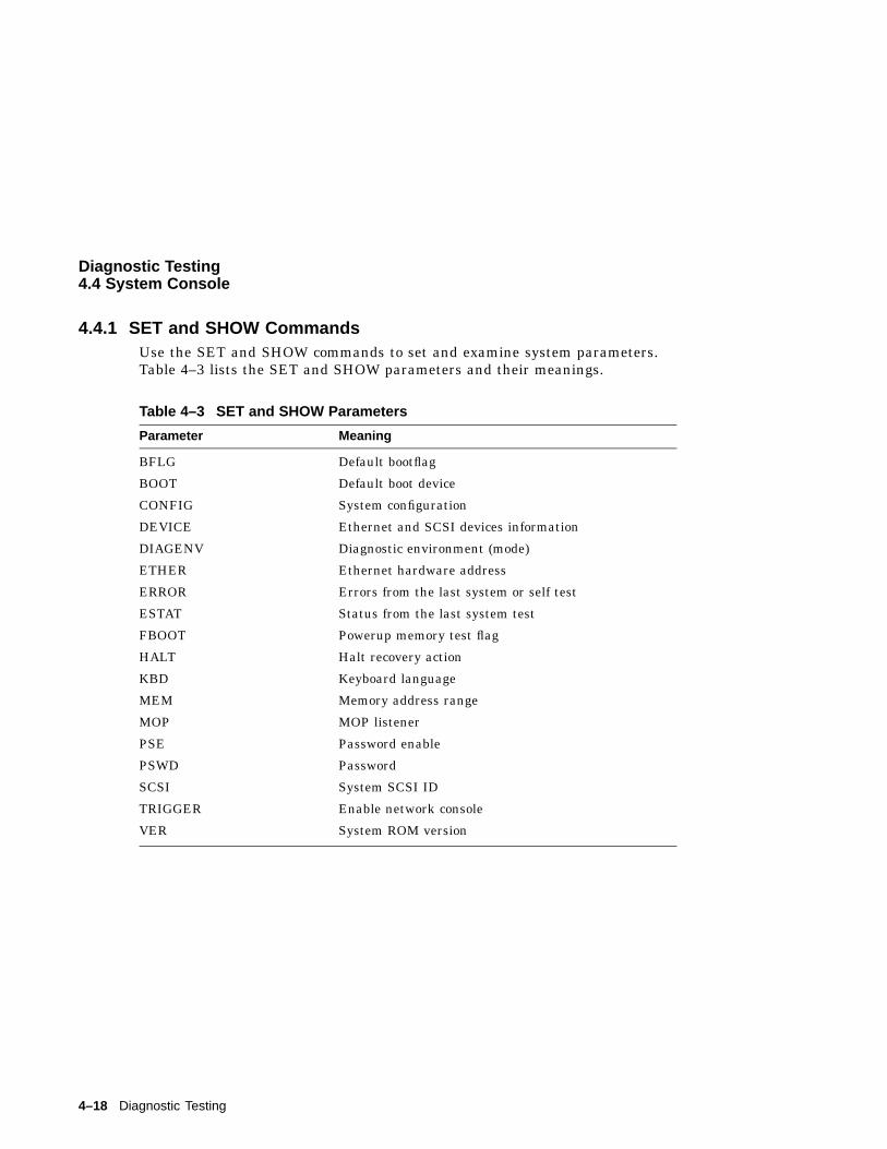
Diagnostic Testing4.4 System Console
4.4.1 SET and SHOW CommandsUse the SET and SHOW commands to set and examine system parameters.Table 4–3 lists the SET and SHOW parameters and their meanings.
Table 4–3 SET and SHOW Parameters
Parameter Meaning
BFLG Default bootflag
BOOT Default boot device
CONFIG System configuration
DEVICE Ethernet and SCSI devices information
DIAGENV Diagnostic environment (mode)
ETHER Ethernet hardware address
ERROR Errors from the last system or self test
ESTAT Status from the last system test
FBOOT Powerup memory test flag
HALT Halt recovery action
KBD Keyboard language
MEM Memory address range
MOP MOP listener
PSE Password enable
PSWD Password
SCSI System SCSI ID
TRIGGER Enable network console
VER System ROM version
4–18 Diagnostic Testing
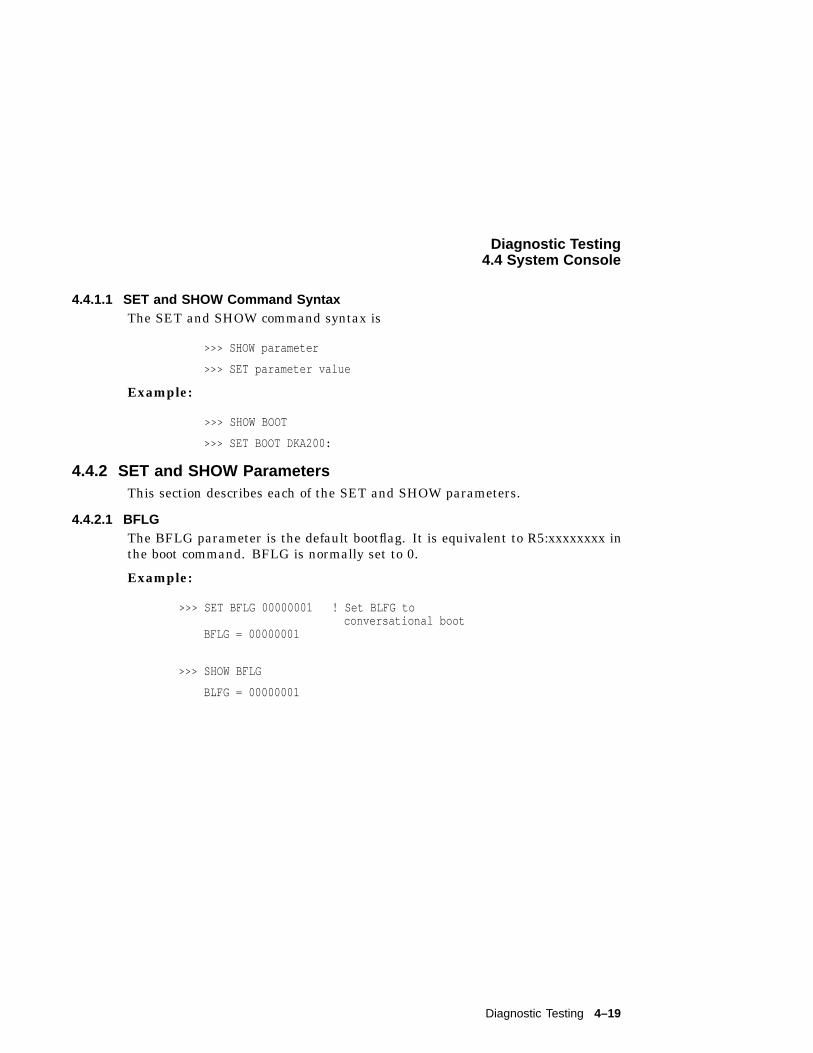
Diagnostic Testing4.4 System Console
4.4.1.1 SET and SHOW Command SyntaxThe SET and SHOW command syntax is
>>> SHOW parameter
>>> SET parameter value
Example:
>>> SHOW BOOT
>>> SET BOOT DKA200:
4.4.2 SET and SHOW ParametersThis section describes each of the SET and SHOW parameters.
4.4.2.1 BFLGThe BFLG parameter is the default bootflag. It is equivalent to R5:xxxxxxxx inthe boot command. BFLG is normally set to 0.
Example:
>>> SET BFLG 00000001 ! Set BLFG toconversational boot
BFLG = 00000001
>>> SHOW BFLG
BLFG = 00000001
Diagnostic Testing 4–19
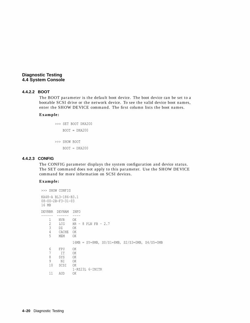
Diagnostic Testing4.4 System Console
4.4.2.2 BOOTThe BOOT parameter is the default boot device. The boot device can be set to abootable SCSI drive or the network device. To see the valid device boot names,enter the SHOW DEVICE command. The first column lists the boot names.
Example:
>>> SET BOOT DKA200
BOOT = DKA200
>>> SHOW BOOT
BOOT = DKA200
4.4.2.3 CONFIGThe CONFIG parameter displays the system configuration and device status.The SET command does not apply to this parameter. Use the SHOW DEVICEcommand for more information on SCSI devices.
Example:
>>> SHOW CONFIG
KA48-A BL3-186-B3.108-00-2B-F3-31-0316 MB
DEVNBR DEVNAM INFO------ ------ ----
1 NVR OK2 LCG HR - 8 PLN FB - 2.73 DZ OK4 CACHE OK5 MEM OK
16MB = SY=8MB, S0/S1=8MB, S2/S3=0MB, S4/S5=0MB
6 FPU OK7 IT OK8 SYS OK9 NI OK10 SCSI OK
1-RZ23L 6-INITR11 AUD OK
4–20 Diagnostic Testing
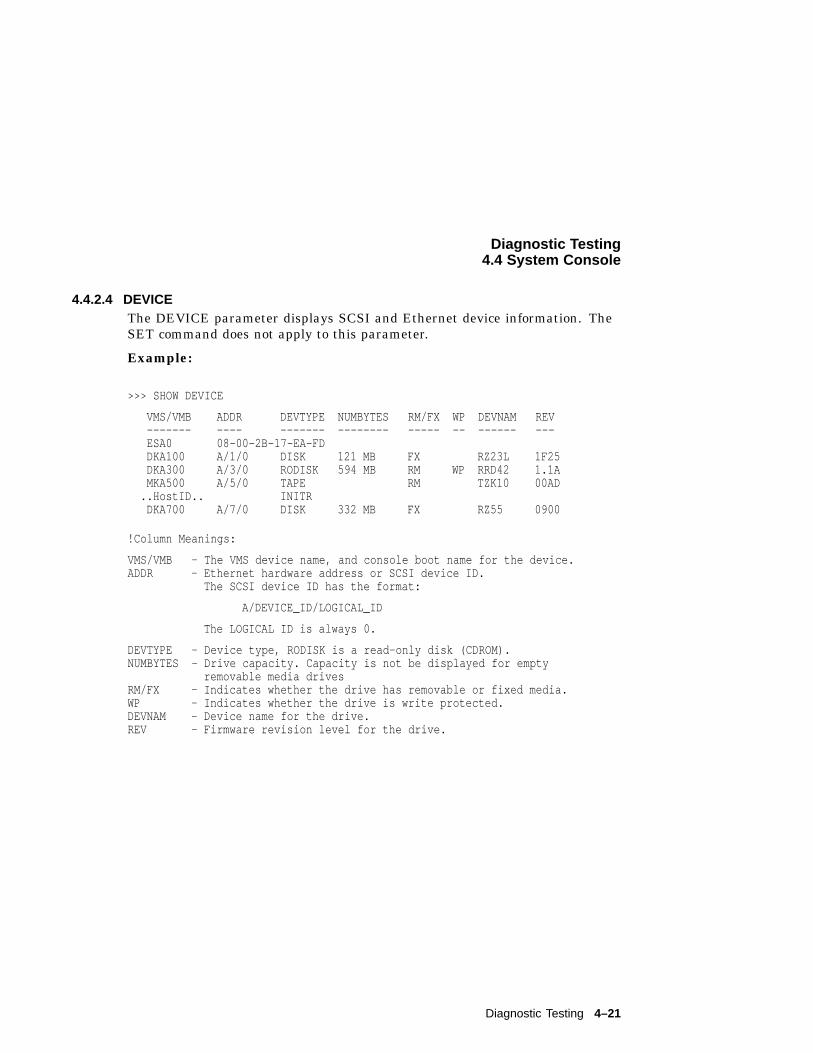
Diagnostic Testing4.4 System Console
4.4.2.4 DEVICEThe DEVICE parameter displays SCSI and Ethernet device information. TheSET command does not apply to this parameter.
Example:
>>> SHOW DEVICE
VMS/VMB ADDR DEVTYPE NUMBYTES RM/FX WP DEVNAM REV------- ---- ------- -------- ----- -- ------ ---ESA0 08-00-2B-17-EA-FDDKA100 A/1/0 DISK 121 MB FX RZ23L 1F25DKA300 A/3/0 RODISK 594 MB RM WP RRD42 1.1AMKA500 A/5/0 TAPE RM TZK10 00AD
..HostID.. INITRDKA700 A/7/0 DISK 332 MB FX RZ55 0900
!Column Meanings:
VMS/VMB - The VMS device name, and console boot name for the device.ADDR - Ethernet hardware address or SCSI device ID.
The SCSI device ID has the format:
A/DEVICE_ID/LOGICAL_ID
The LOGICAL ID is always 0.
DEVTYPE - Device type, RODISK is a read-only disk (CDROM).NUMBYTES - Drive capacity. Capacity is not be displayed for empty
removable media drivesRM/FX - Indicates whether the drive has removable or fixed media.WP - Indicates whether the drive is write protected.DEVNAM - Device name for the drive.REV - Firmware revision level for the drive.
Diagnostic Testing 4–21
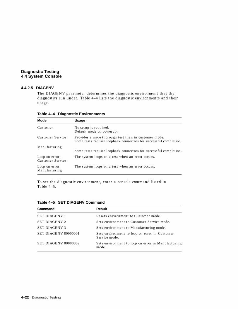
Diagnostic Testing4.4 System Console
4.4.2.5 DIAGENVThe DIAGENV parameter determines the diagnostic environment that thediagnostics run under. Table 4–4 lists the diagnostic environments and theirusage.
Table 4–4 Diagnostic Environments
Mode Usage
Customer No setup is required.Default mode on powerup.
Customer Service Provides a more thorough test than in customer mode.Some tests require loopback connectors for successful completion.
ManufacturingSome tests require loopback connectors for successful completion.
Loop on error;Customer Service
The system loops on a test when an error occurs.
Loop on error;Manufacturing
The system loops on a test when an error occurs.
To set the diagnostic environment, enter a console command listed inTable 4–5.
Table 4–5 SET DIAGENV Command
Command Result
SET DIAGENV 1 Resets environment to Customer mode.
SET DIAGENV 2 Sets environment to Customer Service mode.
SET DIAGENV 3 Sets environment to Manufacturing mode.
SET DIAGENV 80000001 Sets environment to loop on error in CustomerService mode.
SET DIAGENV 80000002 Sets environment to loop on error in Manufacturingmode.
4–22 Diagnostic Testing
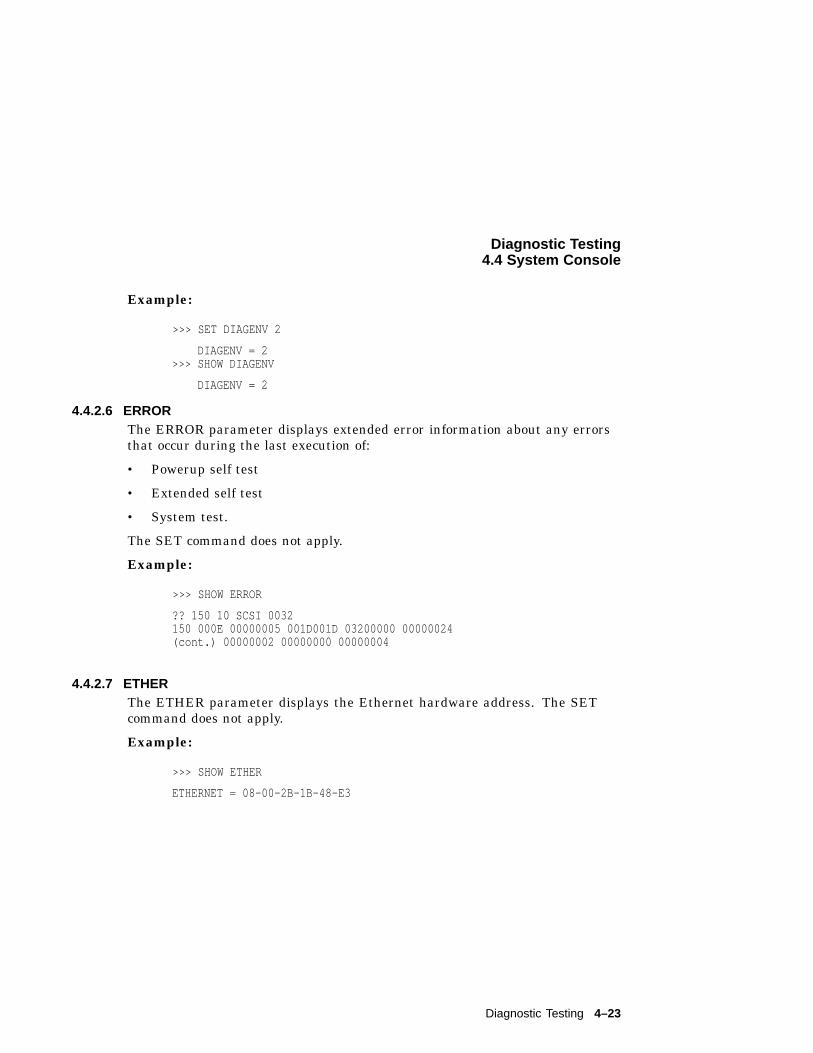
Diagnostic Testing4.4 System Console
Example:
>>> SET DIAGENV 2
DIAGENV = 2>>> SHOW DIAGENV
DIAGENV = 2
4.4.2.6 ERRORThe ERROR parameter displays extended error information about any errorsthat occur during the last execution of:
• Powerup self test
• Extended self test
• System test.
The SET command does not apply.
Example:
>>> SHOW ERROR
?? 150 10 SCSI 0032150 000E 00000005 001D001D 03200000 00000024(cont.) 00000002 00000000 00000004
4.4.2.7 ETHERThe ETHER parameter displays the Ethernet hardware address. The SETcommand does not apply.
Example:
>>> SHOW ETHER
ETHERNET = 08-00-2B-1B-48-E3
Diagnostic Testing 4–23
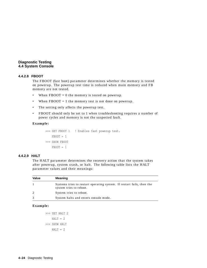
Diagnostic Testing4.4 System Console
4.4.2.8 FBOOTThe FBOOT (fast boot) parameter determines whether the memory is testedon powerup. The powerup test time is reduced when main memory and FBmemory are not tested.
• When FBOOT = 0 the memory is tested on powerup.
• When FBOOT = 1 the memory test is not done on powerup.
• The setting only affects the powerup test.
• FBOOT should only be set to 1 when troubleshooting requires a number ofpower cycles and memory is not the suspected fault.
Example:
>>> SET FBOOT 1 ! Enables fast powerup test.
FBOOT = 1
>>> SHOW FBOOT
FBOOT = 1
4.4.2.9 HALTThe HALT parameter determines the recovery action that the system takesafter powerup, system crash, or halt. The following table lists the HALTparameter values and their meanings:
Value Meaning
1 Systems tries to restart operating system. If restart fails, then thesystem tries to reboot.
2 System tries to reboot.
3 System halts and enters console mode.
Example:
>>> SET HALT 2
HALT = 2
>>> SHOW HALT
HALT = 2
4–24 Diagnostic Testing
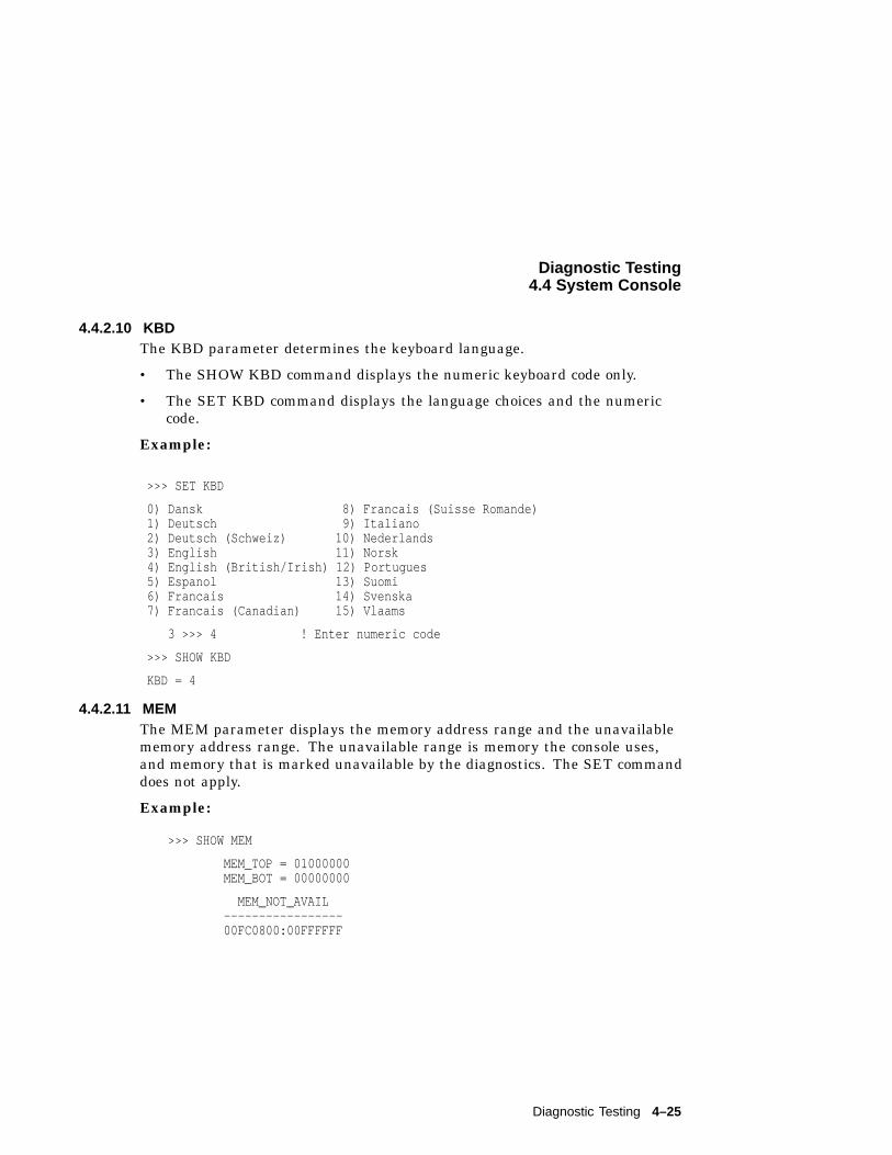
Diagnostic Testing4.4 System Console
4.4.2.10 KBDThe KBD parameter determines the keyboard language.
• The SHOW KBD command displays the numeric keyboard code only.
• The SET KBD command displays the language choices and the numericcode.
Example:
>>> SET KBD
0) Dansk 8) Francais (Suisse Romande)1) Deutsch 9) Italiano2) Deutsch (Schweiz) 10) Nederlands3) English 11) Norsk4) English (British/Irish) 12) Portugues5) Espanol 13) Suomi6) Francais 14) Svenska7) Francais (Canadian) 15) Vlaams
3 >>> 4 ! Enter numeric code
>>> SHOW KBD
KBD = 4
4.4.2.11 MEMThe MEM parameter displays the memory address range and the unavailablememory address range. The unavailable range is memory the console uses,and memory that is marked unavailable by the diagnostics. The SET commanddoes not apply.
Example:
>>> SHOW MEM
MEM_TOP = 01000000MEM_BOT = 00000000
MEM_NOT_AVAIL-----------------00FC0800:00FFFFFF
Diagnostic Testing 4–25
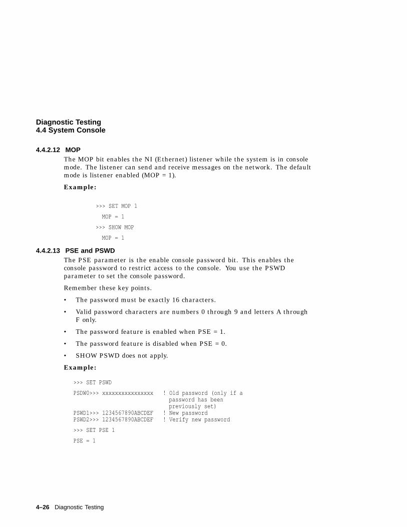
Diagnostic Testing4.4 System Console
4.4.2.12 MOPThe MOP bit enables the NI (Ethernet) listener while the system is in consolemode. The listener can send and receive messages on the network. The defaultmode is listener enabled (MOP = 1).
Example:
>>> SET MOP 1
MOP = 1
>>> SHOW MOP
MOP = 1
4.4.2.13 PSE and PSWDThe PSE parameter is the enable console password bit. This enables theconsole password to restrict access to the console. You use the PSWDparameter to set the console password.
Remember these key points.
• The password must be exactly 16 characters.
• Valid password characters are numbers 0 through 9 and letters A throughF only.
• The password feature is enabled when PSE = 1.
• The password feature is disabled when PSE = 0.
• SHOW PSWD does not apply.
Example:
>>> SET PSWD
PSDW0>>> xxxxxxxxxxxxxxxx ! Old password (only if apassword has beenpreviously set)
PSWD1>>> 1234567890ABCDEF ! New passwordPSWD2>>> 1234567890ABCDEF ! Verify new password
>>> SET PSE 1
PSE = 1
4–26 Diagnostic Testing
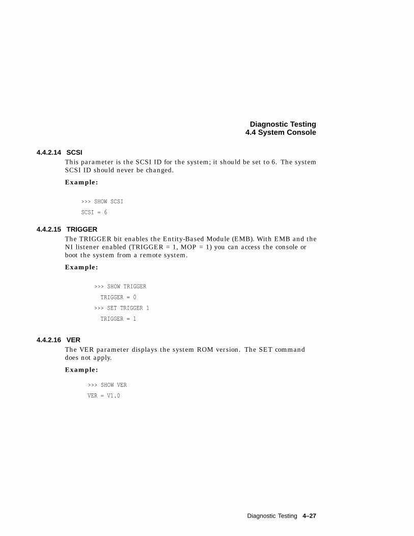
Diagnostic Testing4.4 System Console
4.4.2.14 SCSIThis parameter is the SCSI ID for the system; it should be set to 6. The systemSCSI ID should never be changed.
Example:
>>> SHOW SCSI
SCSI = 6
4.4.2.15 TRIGGERThe TRIGGER bit enables the Entity-Based Module (EMB). With EMB and theNI listener enabled (TRIGGER = 1, MOP = 1) you can access the console orboot the system from a remote system.
Example:
>>> SHOW TRIGGER
TRIGGER = 0
>>> SET TRIGGER 1
TRIGGER = 1
4.4.2.16 VERThe VER parameter displays the system ROM version. The SET commanddoes not apply.
Example:
>>> SHOW VER
VER = V1.0
Diagnostic Testing 4–27
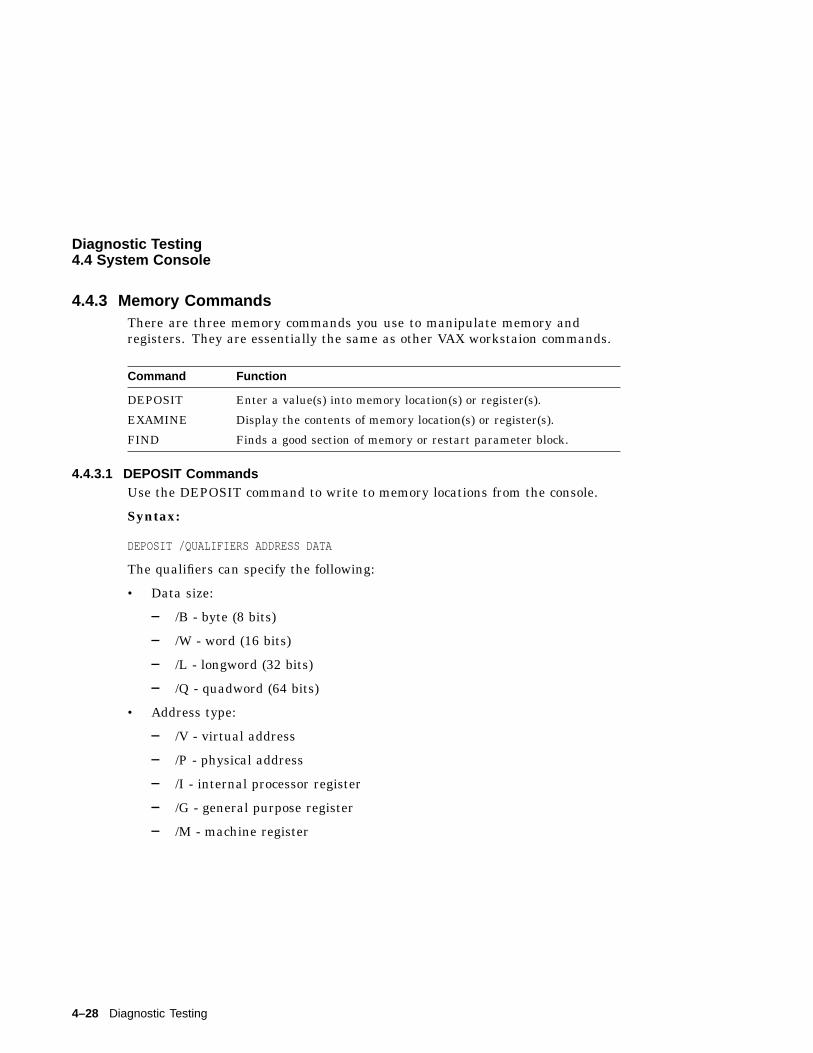
Diagnostic Testing4.4 System Console
4.4.3 Memory CommandsThere are three memory commands you use to manipulate memory andregisters. They are essentially the same as other VAX workstaion commands.
Command Function
DEPOSIT Enter a value(s) into memory location(s) or register(s).
EXAMINE Display the contents of memory location(s) or register(s).
FIND Finds a good section of memory or restart parameter block.
4.4.3.1 DEPOSIT CommandsUse the DEPOSIT command to write to memory locations from the console.
Syntax:
DEPOSIT /QUALIFIERS ADDRESS DATA
The qualifiers can specify the following:
• Data size:
/B - byte (8 bits)
/W - word (16 bits)
/L - longword (32 bits)
/Q - quadword (64 bits)
• Address type:
/V - virtual address
/P - physical address
/I - internal processor register
/G - general purpose register
/M - machine register
4–28 Diagnostic Testing
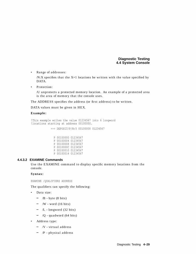
Diagnostic Testing4.4 System Console
• Range of addresses:
/N:X specifies that the X+1 locations be written with the value specified byDATA.
• Protection:
/U unprotects a protected memory location. An example of a protected areais the area of memory that the console uses.
The ADDRESS specifies the address (or first address) to be written.
DATA values must be given in HEX.
Example:
!This example writes the value 01234567 into 6 longword!locations starting at address 00100000.
>>> DEPOSIT/P/N:5 00100000 01234567
P 00100000 01234567P 00100004 01234567P 00100008 01234567P 0010000C 01234567P 00100010 01234567P 00100014 01234567
4.4.3.2 EXAMINE CommandsUse the EXAMINE command to display specific memory locations from theconsole.
Syntax:
EXAMINE /QUALIFIERS ADDRESS
The qualifiers can specify the following:
• Data size:
/B - byte (8 bits)
/W - word (16 bits)
/L - longword (32 bits)
/Q - quadword (64 bits)
• Address type:
/V - virtual address
/P - physical address
Diagnostic Testing 4–29
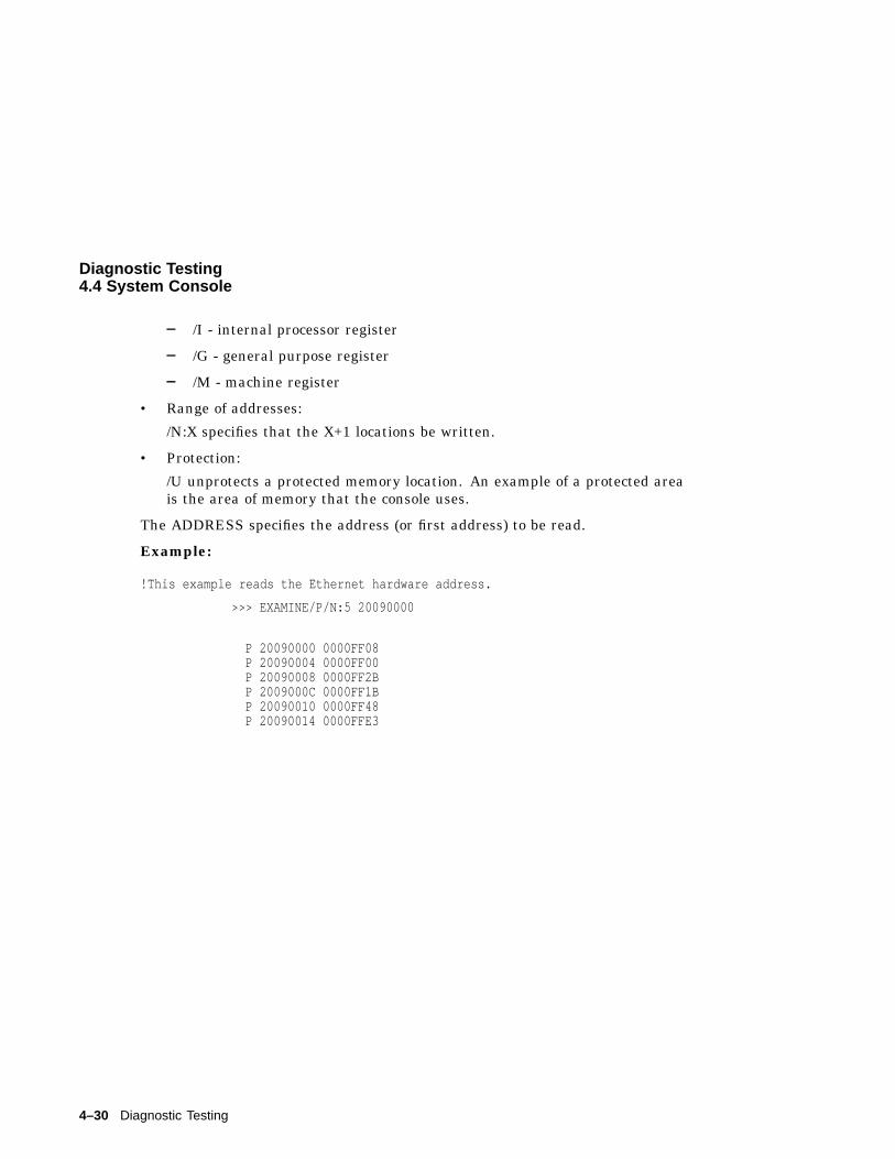
Diagnostic Testing4.4 System Console
/I - internal processor register
/G - general purpose register
/M - machine register
• Range of addresses:
/N:X specifies that the X+1 locations be written.
• Protection:
/U unprotects a protected memory location. An example of a protected areais the area of memory that the console uses.
The ADDRESS specifies the address (or first address) to be read.
Example:
!This example reads the Ethernet hardware address.
>>> EXAMINE/P/N:5 20090000
P 20090000 0000FF08P 20090004 0000FF00P 20090008 0000FF2BP 2009000C 0000FF1BP 20090010 0000FF48P 20090014 0000FFE3
4–30 Diagnostic Testing
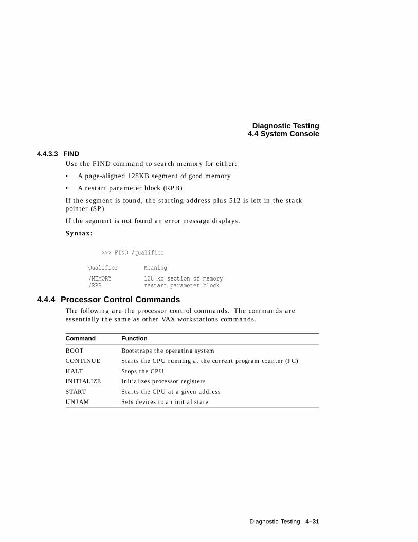
Diagnostic Testing4.4 System Console
4.4.3.3 FINDUse the FIND command to search memory for either:
• A page-aligned 128KB segment of good memory
• A restart parameter block (RPB)
If the segment is found, the starting address plus 512 is left in the stackpointer (SP)
If the segment is not found an error message displays.
Syntax:
>>> FIND /qualifier
Qualifier Meaning
/MEMORY 128 kb section of memory/RPB restart parameter block
4.4.4 Processor Control CommandsThe following are the processor control commands. The commands areessentially the same as other VAX workstations commands.
Command Function
BOOT Bootstraps the operating system
CONTINUE Starts the CPU running at the current program counter (PC)
HALT Stops the CPU
INITIALIZE Initializes processor registers
START Starts the CPU at a given address
UNJAM Sets devices to an initial state
Diagnostic Testing 4–31
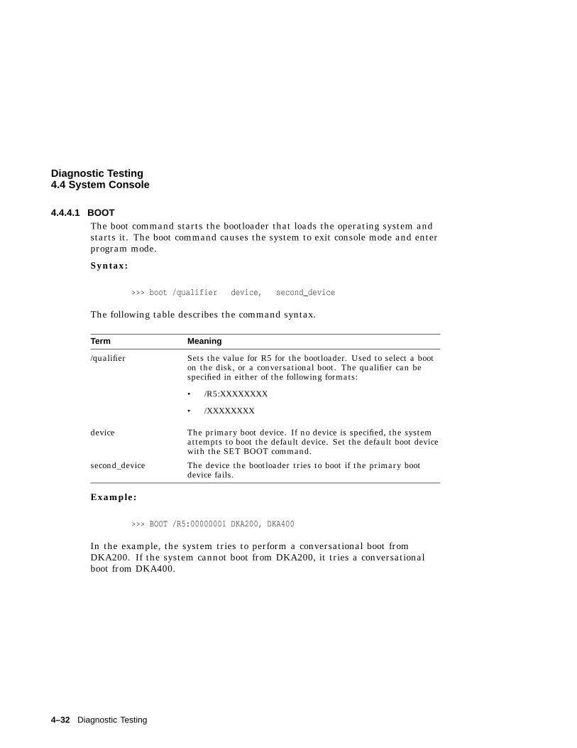
Diagnostic Testing4.4 System Console
4.4.4.1 BOOTThe boot command starts the bootloader that loads the operating system andstarts it. The boot command causes the system to exit console mode and enterprogram mode.
Syntax:
>>> boot /qualifier device, second_device
The following table describes the command syntax.
Term Meaning
/qualifier Sets the value for R5 for the bootloader. Used to select a booton the disk, or a conversational boot. The qualifier can bespecified in either of the following formats:
• /R5:XXXXXXXX
• /XXXXXXXX
device The primary boot device. If no device is specified, the systemattempts to boot the default device. Set the default boot devicewith the SET BOOT command.
second_device The device the bootloader tries to boot if the primary bootdevice fails.
Example:
>>> BOOT /R5:00000001 DKA200, DKA400
In the example, the system tries to perform a conversational boot fromDKA200. If the system cannot boot from DKA200, it tries a conversationalboot from DKA400.
4–32 Diagnostic Testing
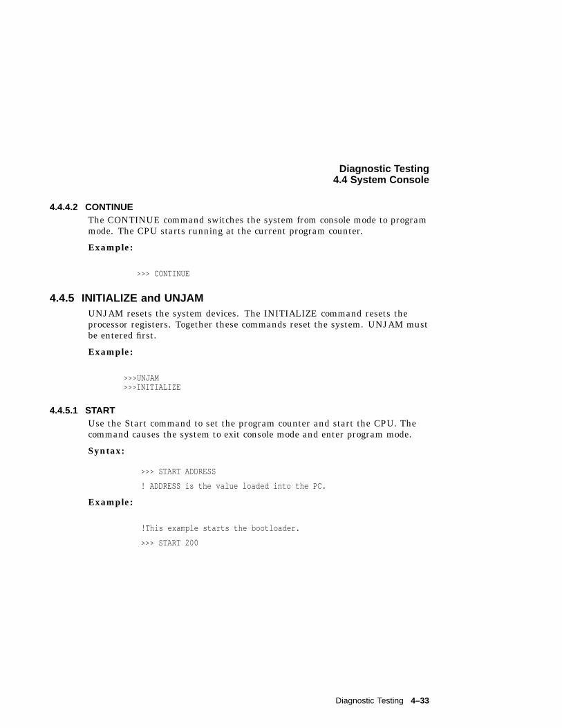
Diagnostic Testing4.4 System Console
4.4.4.2 CONTINUEThe CONTINUE command switches the system from console mode to programmode. The CPU starts running at the current program counter.
Example:
>>> CONTINUE
4.4.5 INITIALIZE and UNJAMUNJAM resets the system devices. The INITIALIZE command resets theprocessor registers. Together these commands reset the system. UNJAM mustbe entered first.
Example:
>>>UNJAM>>>INITIALIZE
4.4.5.1 STARTUse the Start command to set the program counter and start the CPU. Thecommand causes the system to exit console mode and enter program mode.
Syntax:
>>> START ADDRESS
! ADDRESS is the value loaded into the PC.
Example:
!This example starts the bootloader.
>>> START 200
Diagnostic Testing 4–33
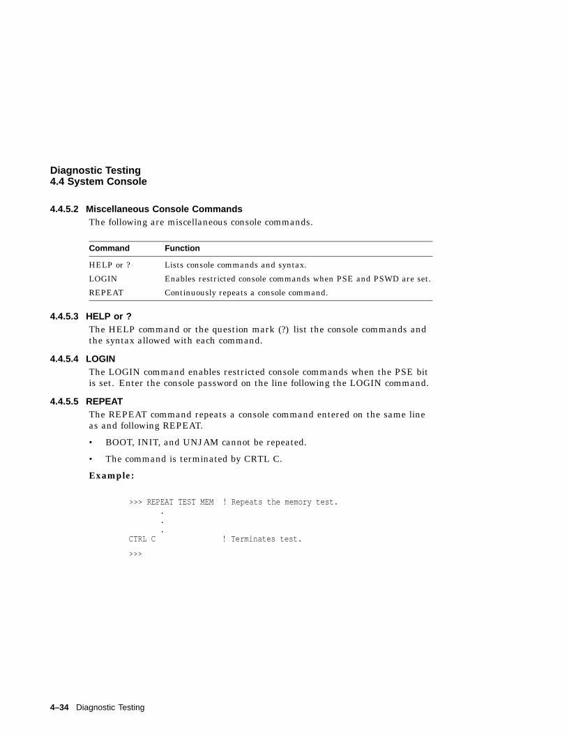
Diagnostic Testing4.4 System Console
4.4.5.2 Miscellaneous Console CommandsThe following are miscellaneous console commands.
Command Function
HELP or ? Lists console commands and syntax.
LOGIN Enables restricted console commands when PSE and PSWD are set.
REPEAT Continuously repeats a console command.
4.4.5.3 HELP or ?The HELP command or the question mark (?) list the console commands andthe syntax allowed with each command.
4.4.5.4 LOGINThe LOGIN command enables restricted console commands when the PSE bitis set. Enter the console password on the line following the LOGIN command.
4.4.5.5 REPEATThe REPEAT command repeats a console command entered on the same lineas and following REPEAT.
• BOOT, INIT, and UNJAM cannot be repeated.
• The command is terminated by CRTL C.
Example:
>>> REPEAT TEST MEM ! Repeats the memory test....
CTRL C ! Terminates test.
>>>
4–34 Diagnostic Testing
5Removing and Replacing FRUs
This chapter describes how to remove and replace the field replaceable units(FRUs) in the VAXstation 4000 VLC system box. Table D–1 lists the VLCFRUs and their part numbers.
Each section describes the removal procedure for the FRU. Unless otherwisespecified, you install a FRU by reversing the steps in the removal procedure.
5.1 Cautions and WarningsRemoving and replacing FRUs must be done by only Digital Services personnelor maintenance personnel trained specifically by Digital.
Note
It is the customer’s responsibility to back up all software before theDigital Services Representative arrives. This ensures that data isnot lost during the service process. The customer should also shutdown the workstation software. Before performing any maintenancework, Digital Services personnel must confirm that the customer hascompleted both of these tasks.
caution
Electrostatic discharge (ESD) can damage integrated circuits. Alwaysuse a grounded wrist strap (part number 29-11762-00) and work-surface-to-earth ground when removing and replacing any FRU.
warning
Turn power to the mointor off, then disconnect the power cord from thepower source before performing any of these procedures.
Removing and Replacing FRUs 5–1
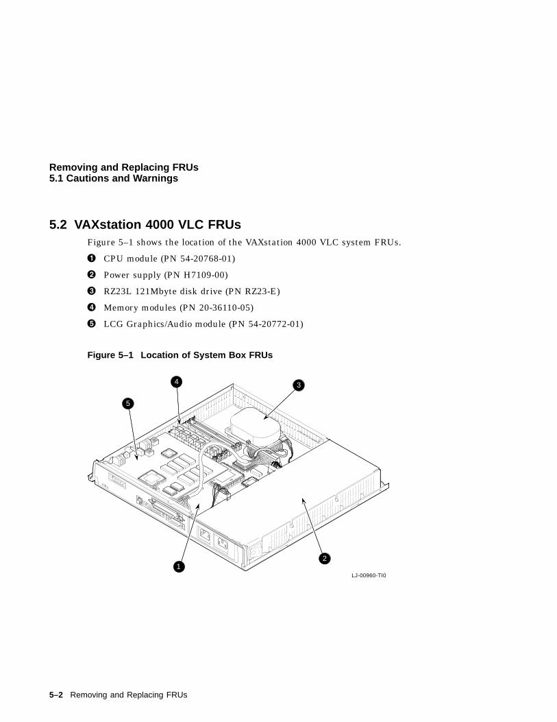
Removing and Replacing FRUs5.1 Cautions and Warnings
5.2 VAXstation 4000 VLC FRUsFigure 5–1 shows the location of the VAXstation 4000 VLC system FRUs.
! CPU module (PN 54-20768-01)
" Power supply (PN H7109-00)
# RZ23L 121Mbyte disk drive (PN RZ23-E)
$ Memory modules (PN 20-36110-05)
% LCG Graphics/Audio module (PN 54-20772-01)
Figure 5–1 Location of System Box FRUs
22%
38%
LJ-00960-TI0
J12
J2
J3J4
J5J6
3
12
4
5
5–2 Removing and Replacing FRUs
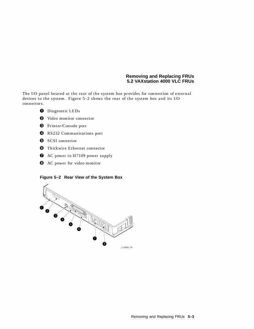
Removing and Replacing FRUs5.2 VAXstation 4000 VLC FRUs
The I/O panel located at the rear of the system box provides for connection of externaldevices to the system. Figure 5–2 shows the rear of the system box and its I/Oconnectors.
! Diagnostic LEDs
" Video monitor connector
# Printer/Console port
$ RS232 Communications port
% SCSI connector
& Thickwire Ethernet connector
' AC power to H7109 power supply
( AC power for video monitor
Figure 5–2 Rear View of the System Box
LJ-00961-TI0
12
3
4
5
6
7
8
Removing and Replacing FRUs 5–3
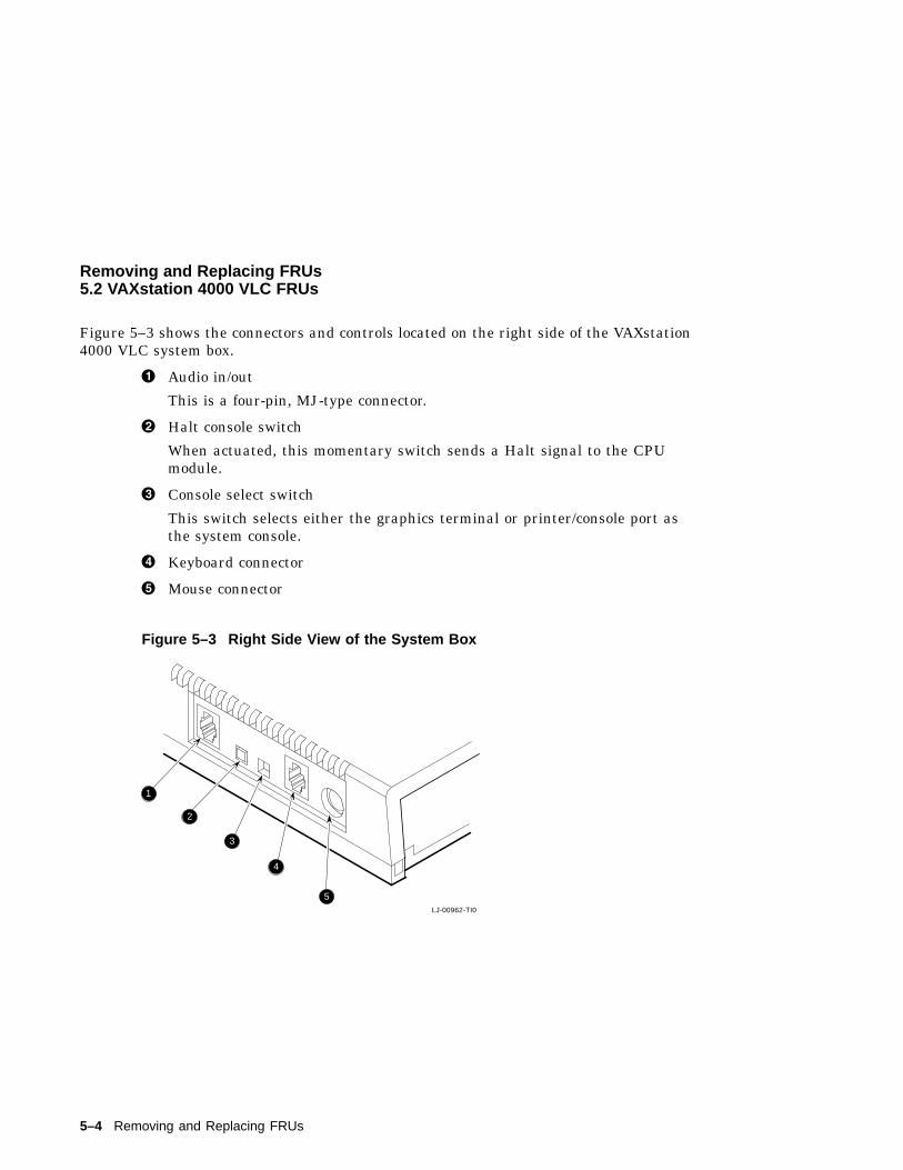
Removing and Replacing FRUs5.2 VAXstation 4000 VLC FRUs
Figure 5–3 shows the connectors and controls located on the right side of the VAXstation4000 VLC system box.
! Audio in/out
This is a four-pin, MJ-type connector.
" Halt console switch
When actuated, this momentary switch sends a Halt signal to the CPUmodule.
# Console select switch
This switch selects either the graphics terminal or printer/console port asthe system console.
$ Keyboard connector
% Mouse connector
Figure 5–3 Right Side View of the System Box
LJ-00962-TI0
1
2
3
4
5
5–4 Removing and Replacing FRUs
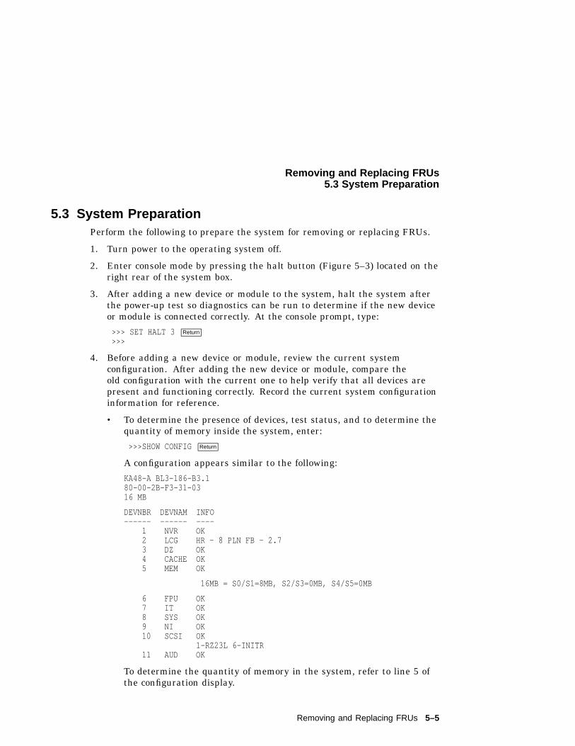
Removing and Replacing FRUs5.3 System Preparation
5.3 System PreparationPerform the following to prepare the system for removing or replacing FRUs.
1. Turn power to the operating system off.
2. Enter console mode by pressing the halt button (Figure 5–3) located on theright rear of the system box.
3. After adding a new device or module to the system, halt the system afterthe power-up test so diagnostics can be run to determine if the new deviceor module is connected correctly. At the console prompt, type:
>>> SET HALT 3 Return
>>>
4. Before adding a new device or module, review the current systemconfiguration. After adding the new device or module, compare theold configuration with the current one to help verify that all devices arepresent and functioning correctly. Record the current system configurationinformation for reference.
• To determine the presence of devices, test status, and to determine thequantity of memory inside the system, enter:
>>>SHOW CONFIGReturn
A configuration appears similar to the following:
KA48-A BL3-186-B3.180-00-2B-F3-31-0316 MB
DEVNBR DEVNAM INFO------ ------ ----
1 NVR OK2 LCG HR - 8 PLN FB - 2.73 DZ OK4 CACHE OK5 MEM OK
16MB = S0/S1=8MB, S2/S3=0MB, S4/S5=0MB
6 FPU OK7 IT OK8 SYS OK9 NI OK10 SCSI OK
1-RZ23L 6-INITR11 AUD OK
To determine the quantity of memory in the system, refer to line 5 ofthe configuration display.
Removing and Replacing FRUs 5–5
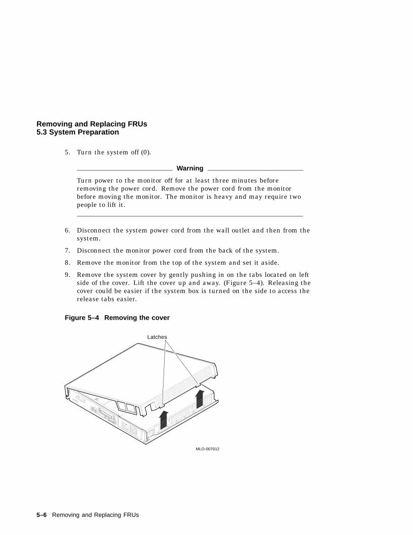
Removing and Replacing FRUs5.3 System Preparation
5. Turn the system off (0).
Warning
Turn power to the monitor off for at least three minutes beforeremoving the power cord. Remove the power cord from the monitorbefore moving the monitor. The monitor is heavy and may require twopeople to lift it.
6. Disconnect the system power cord from the wall outlet and then from thesystem.
7. Disconnect the monitor power cord from the back of the system.
8. Remove the monitor from the top of the system and set it aside.
9. Remove the system cover by gently pushing in on the tabs located on leftside of the cover. Lift the cover up and away. (Figure 5–4). Releasing thecover could be easier if the system box is turned on the side to access therelease tabs easier.
Figure 5–4 Removing the cover
C1C2
MLO-007012
Latches
5–6 Removing and Replacing FRUs
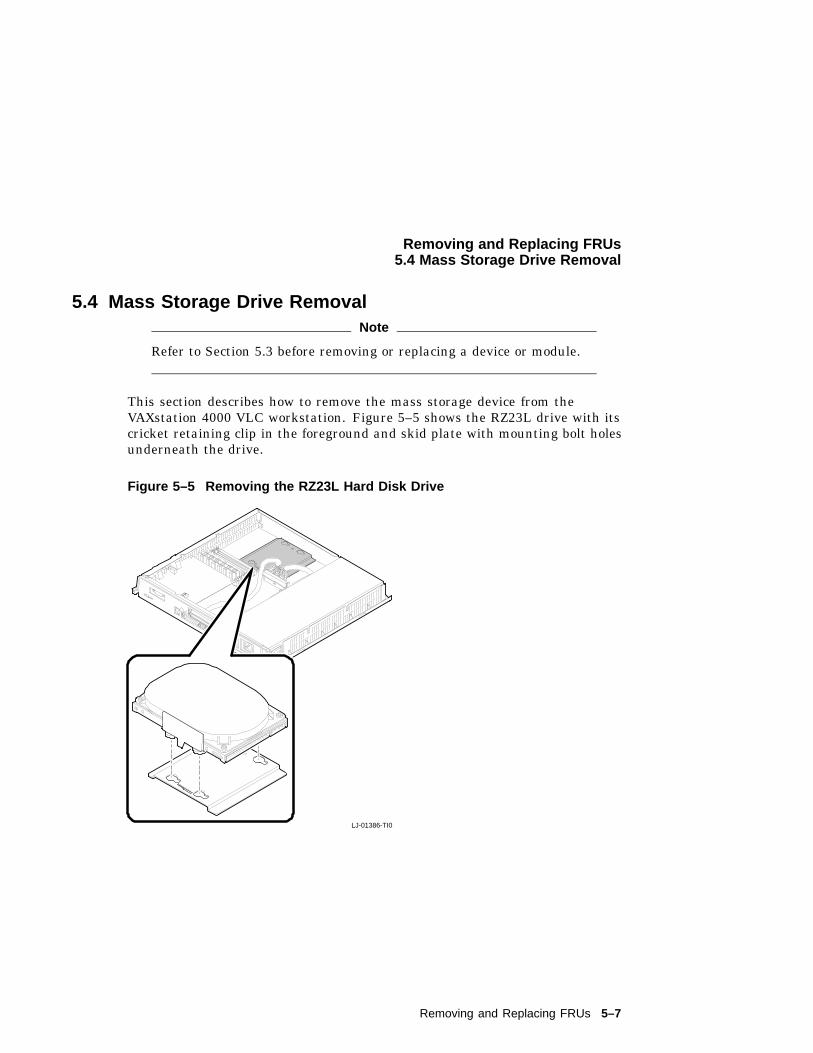
Removing and Replacing FRUs5.4 Mass Storage Drive Removal
5.4 Mass Storage Drive RemovalNote
Refer to Section 5.3 before removing or replacing a device or module.
This section describes how to remove the mass storage device from theVAXstation 4000 VLC workstation. Figure 5–5 shows the RZ23L drive with itscricket retaining clip in the foreground and skid plate with mounting bolt holesunderneath the drive.
Figure 5–5 Removing the RZ23L Hard Disk Drive
C1C2
LJ-01386-TI0
Removing and Replacing FRUs 5–7
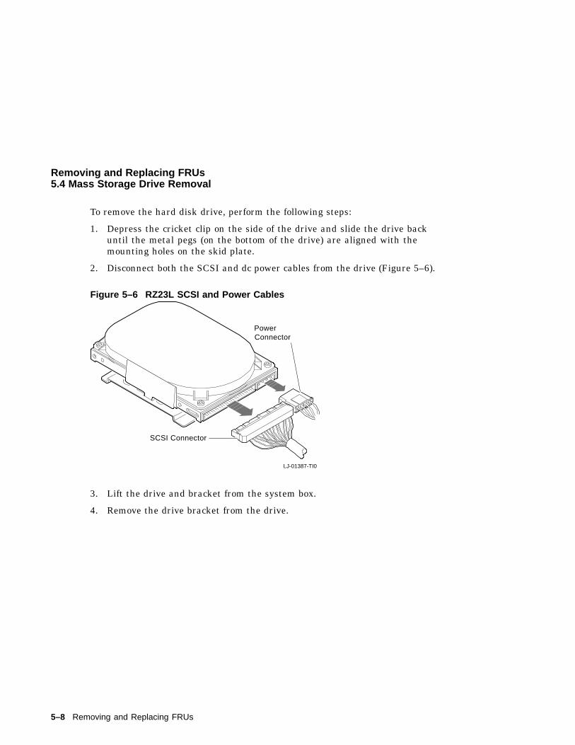
Removing and Replacing FRUs5.4 Mass Storage Drive Removal
To remove the hard disk drive, perform the following steps:
1. Depress the cricket clip on the side of the drive and slide the drive backuntil the metal pegs (on the bottom of the drive) are aligned with themounting holes on the skid plate.
2. Disconnect both the SCSI and dc power cables from the drive (Figure 5–6).
Figure 5–6 RZ23L SCSI and Power Cables
LJ-01387-TI0
SCSI Connector
PowerConnector
3. Lift the drive and bracket from the system box.
4. Remove the drive bracket from the drive.
5–8 Removing and Replacing FRUs
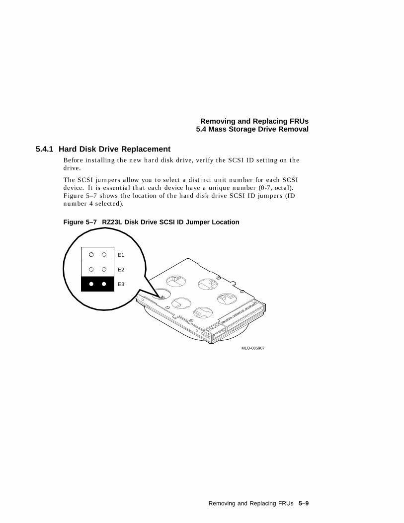
Removing and Replacing FRUs5.4 Mass Storage Drive Removal
5.4.1 Hard Disk Drive ReplacementBefore installing the new hard disk drive, verify the SCSI ID setting on thedrive.
The SCSI jumpers allow you to select a distinct unit number for each SCSIdevice. It is essential that each device have a unique number (0-7, octal).Figure 5–7 shows the location of the hard disk drive SCSI ID jumpers (IDnumber 4 selected).
Figure 5–7 RZ23L Disk Drive SCSI ID Jumper Location
E1E2E3
E1
E2
E3
MLO-005907
Removing and Replacing FRUs 5–9
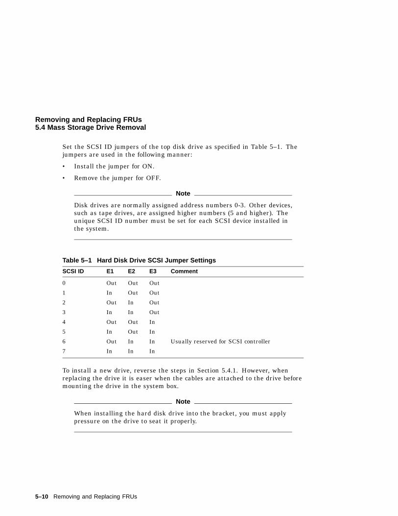
Removing and Replacing FRUs5.4 Mass Storage Drive Removal
Set the SCSI ID jumpers of the top disk drive as specified in Table 5–1. Thejumpers are used in the following manner:
• Install the jumper for ON.
• Remove the jumper for OFF.
Note
Disk drives are normally assigned address numbers 0-3. Other devices,such as tape drives, are assigned higher numbers (5 and higher). Theunique SCSI ID number must be set for each SCSI device installed inthe system.
Table 5–1 Hard Disk Drive SCSI Jumper Settings
SCSI ID E1 E2 E3 Comment
0 Out Out Out
1 In Out Out
2 Out In Out
3 In In Out
4 Out Out In
5 In Out In
6 Out In In Usually reserved for SCSI controller
7 In In In
To install a new drive, reverse the steps in Section 5.4.1. However, whenreplacing the drive it is easer when the cables are attached to the drive beforemounting the drive in the system box.
Note
When installing the hard disk drive into the bracket, you must applypressure on the drive to seat it properly.
5–10 Removing and Replacing FRUs
Removing and Replacing FRUs5.5 Power Supply Removal
5.5 Power Supply RemovalCAUTION
Wear an antistatic wrist strap and place an antistatic mat under thesystem when removing and replacing any modules.
This section describes how to remove the power supply from the VAXstation4000 VLC system box. Figure 5–1 shows the location of the power supply. Toremove the power supply perform the following steps:
1. Disconnect the monitor and power supply power cords from the acconnectors at the rear of the unit.
2. Remove the top cover (Section 5.3, Figure 5–4).
3. Disconnect the power supply power cable from the J13 connector of thesystem module (Figure 5–8).
4. Loosen the two torque screws holding the power supply against the leftside of the system box. Figure 5–8 shows the location of the torque screwsas seen from the rear of the system box.
5. Tilt the power supply up until the bottom clears the system box, then liftthe power supply up and out.
Removing and Replacing FRUs 5–11
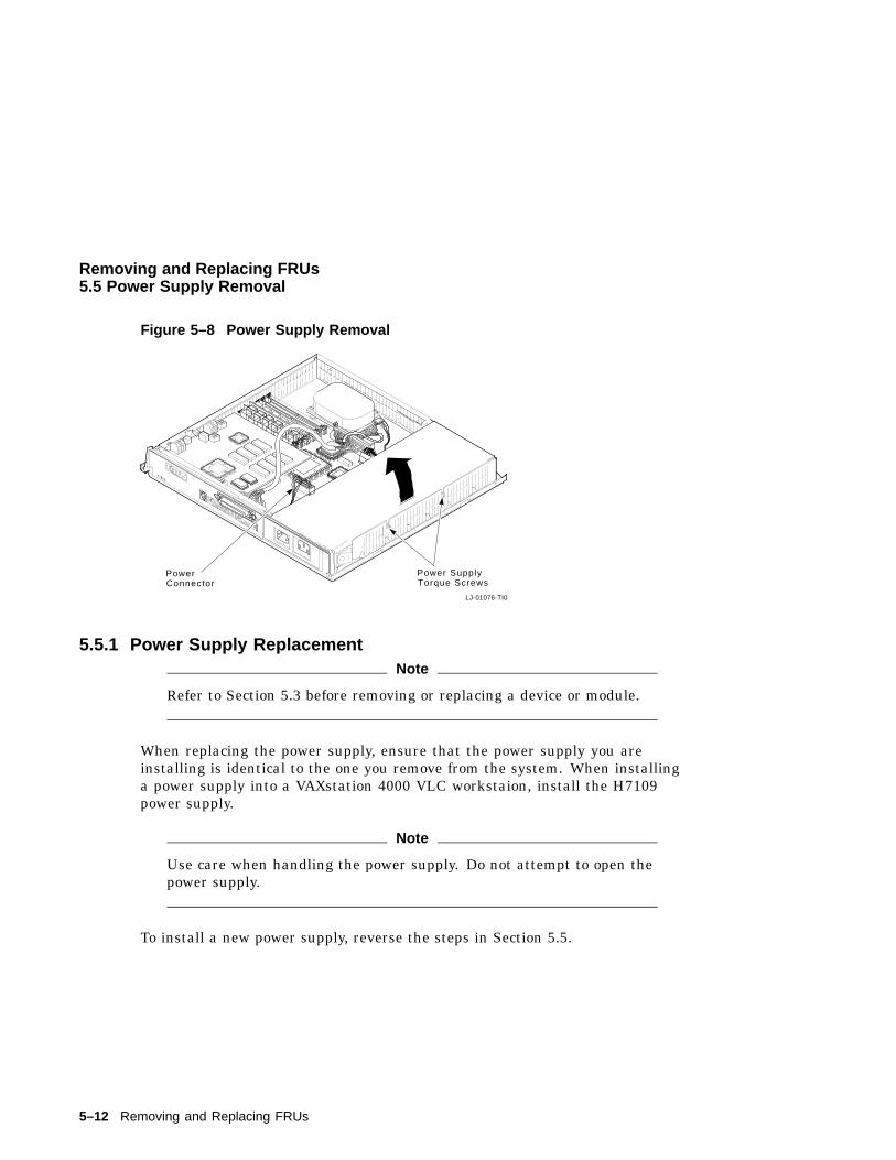
Removing and Replacing FRUs5.5 Power Supply Removal
Figure 5–8 Power Supply Removal
22%
38%
LJ-01076-TI0
J12
J2
J3J4
J5J6
Power SupplyTorque Screws
PowerConnector
5.5.1 Power Supply ReplacementNote
Refer to Section 5.3 before removing or replacing a device or module.
When replacing the power supply, ensure that the power supply you areinstalling is identical to the one you remove from the system. When installinga power supply into a VAXstation 4000 VLC workstaion, install the H7109power supply.
Note
Use care when handling the power supply. Do not attempt to open thepower supply.
To install a new power supply, reverse the steps in Section 5.5.
5–12 Removing and Replacing FRUs
Removing and Replacing FRUs5.6 Removing the LCG Module
5.6 Removing the LCG ModuleCAUTION
Wear an antistatic wrist strap and place an antistatic mat under thesystem when removing and replacing any modules.
To remove the LCG module perform the following steps:
1. Disconnect the power cords (monitor and power supply) from the two acconnectors at the rear of the unit.
2. Locate and remove the two mounting screws of the LCG module.
3. Lift the LCG module up and to the rear until the video jack has cleared theplastic system box enclosure.
To install a new LCG module, reverse the steps in Section 5.6.
5.7 Removing the System ModuleCAUTION
Wear an antistatic wrist strap and place an antistatic mat under thesystem when removing and replacing any modules.
To remove the system module (CPU), perform the following steps:
1. Remove the LCG graphics/audio module.
2. Disconnect the cables attached to the CPU module at the rear of thesystem.
3. Remove the MS40 memory modules.
4. Remove the five rivets and three screws from the front of the CPU module.
5. Remove the system module (CPU) by lifting it enough so that it clears thetwo guides at the right front and left of the module.
6. Using the large center connector, pull the module toward the front of thesystem box and lift it out.
Note
The Ethernet ROM must be removed and installed on the new systemmodule or the NVR settings will be lost.
Removing and Replacing FRUs 5–13
Removing and Replacing FRUs5.7 Removing the System Module
5.7.1 System Module (CPU) ReplacementBe sure to protect the system module from damage due to static charge whenreplacing or removing the system module.
To install a new system module (CPU), reverse the steps in Section 5.7.
5.8 MS40 Memory Module RemovalNote
There must always be at least two memory modules in a VAXstation4000 VLC workstation.
CAUTION 1
Memory module components are easily damaged by static electricity.An antistatic wriststrap should always be worn when installing orremoving memory components.
CAUTION 2
The memory modules are keyed and should be installed in only onedirection. Excessive force applied to a module when it is not properlyaligned with the connector can cause permanent damage to either thememory module or the connector.
CAUTION 3
Wear an antistatic wrist strap and place an antistatic mat under thesystem when removing and replacing any modules.
Note
Memory modules must always be removed starting from the frontof the system. For example, if you are going to replace the moduletowards the rear of the system board, you must remove any modulesstarting at the front and working toward the back. Memory modules
5–14 Removing and Replacing FRUs
Removing and Replacing FRUs5.8 MS40 Memory Module Removal
are numbered on the right edge of the memory connectors located onthe system board.
Removing and Replacing FRUs 5–15
Removing and Replacing FRUs5.8 MS40 Memory Module Removal
This section describes how to remove the MS40 memory module from thesystem. The memory modules are shown in Figure 5–1. To remove the MS40memory modules perform the following steps:
1. Release the two metal retainers at each end of the memory moduleconnector.
2. Rotate the module backward approximately 55 degress to the rear of theunit and lift it out of the slot.
Note
Failure to release the two module retainers will permanently damagethe module connector located on the system board.
5.8.0.1 MS40 Memory Module ReplacementNote
There is only one type of memory module available for the VAXstation4000 VLC workstation, the 4 Mbyte (MS40-AA). Be sure that you havethe correct module before installation. To identify the module locatethe etch on the left side of the memory module.
To install a new MS40 memory module perform the following steps:
1. Place the module in the connector with it tilted at approximately 55degrees backwards. Be sure the double notched lower corner of the moduleis away from the power supply.
2. Pivot the module upwards until the metal tabs connect with the moduleand latch it into place.
5–16 Removing and Replacing FRUs
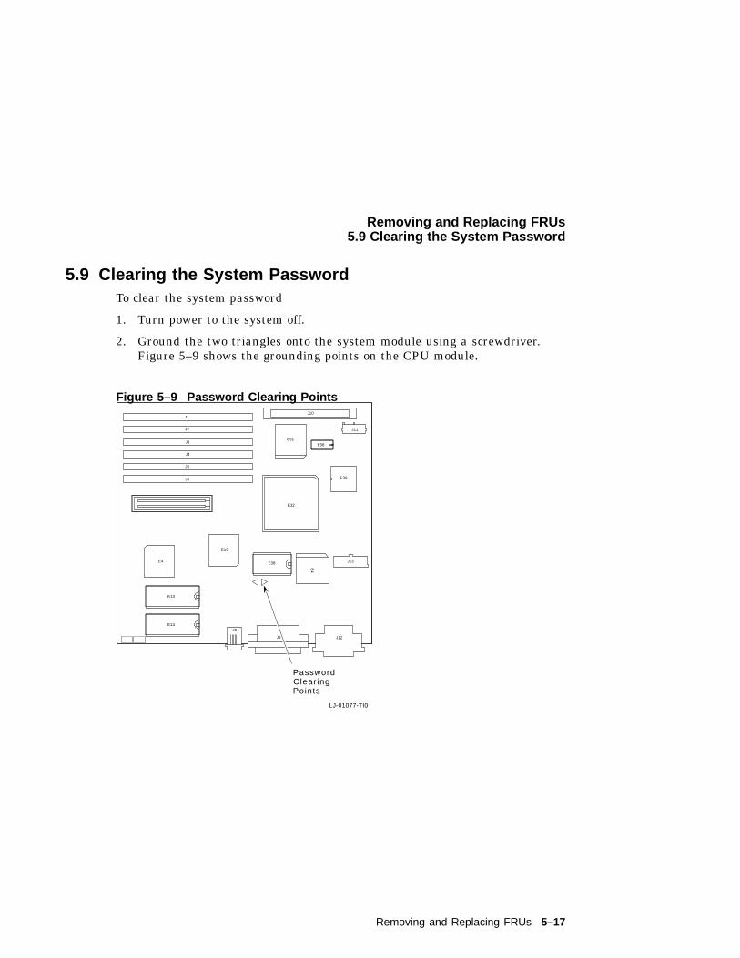
Removing and Replacing FRUs5.9 Clearing the System Password
5.9 Clearing the System PasswordTo clear the system password
1. Turn power to the system off.
2. Ground the two triangles onto the system module using a screwdriver.Figure 5–9 shows the grounding points on the CPU module.
Figure 5–9 Password Clearing Points
LJ-01077-TI0
E39
J13
J12J9
J8
E13
E14
E38
E38
J11
J10
E31
E4
E19
J1
J2
J3
J4
J5
J6
E32
E4
PasswordClear ingPoints
Removing and Replacing FRUs 5–17
Removing and Replacing FRUs5.10 Testing the VAXstation 4000 VLC System
5.10 Testing the VAXstation 4000 VLC SystemThis section describes how to test the system after removing or replacing anyFRUs.
5.10.1 Restore the SystemBefore you can test the system, you must restore the system to its previousoperating state. To restore the system, perform the following steps:
1. Replace the system cover. Align the teeth of the cover with the teeth on theside of the system enclosure and lower the cover until it clicks into place.
2. Reconnect any cables that you disconnected from the rear of the system.
3. Reconnect the monitor.
4. Plug the system power cord into the wall outlet.
5. Turn power to the system on.
5–18 Removing and Replacing FRUs
Removing and Replacing FRUs5.10 Testing the VAXstation 4000 VLC System
5.10.2 Test the SystemTest the system to confirm that all devices and modules are connected correctly.Do the following to test the system:
1. Note any power-up error or status messages on the monitor screen.
2. Display the system device configuration by using the SHOW CONFIGcommand. (See Section 5.3.) Compare the latest configuration display withthe configuration display you viewed during site preparation. You shouldsee the new device and the other devices present in the system. Verify thatno error messages appears on the monitor screen.
3. Verify that all devices are interacting properly by using the TEST 1:11command to run the expanded self test.
4. Verify that drives are set to the correct SCSI IDs using the SHOW DEVICEcommand.
5. If problems occur, check the following to ensure that
a. All cables inside and outside the system are connected.
b. All modules are fully seated in the connectors.
c. SCSI IDs are set correctly. Each drive should have a differenct SCSIId.
Removing and Replacing FRUs 5–19
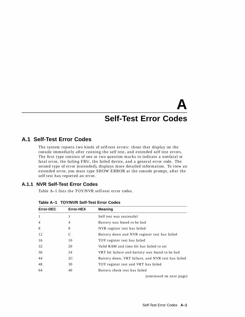
ASelf-Test Error Codes
A.1 Self-Test Error CodesThe system reports two kinds of self-test errors: those that display on theconsole immediatly after running the self test, and extended self test errors.The first type consists of one or two question marks to indicate a nonfatal orfatal error, the failing FRU, the failed device, and a general error code. Thesecond type of error (extended), displays more detailed information. To view anextended error, you must type SHOW ERROR at the console prompt, after theself test has reported an error.
A.1.1 NVR Self-Test Error CodesTable A–1 lists the TOY/NVR self-test error codes.
Table A–1 TOY/NVR Self-Test Error Codes
Error-DEC Error-HEX Meaning
1 1 Self test was successful
4 4 Battery was found to be bad
8 8 NVR register test has failed
12 C Battery down and NVR register test has failed
16 10 TOY register test has failed
32 20 Valid RAM and time bit has failed to set
36 24 VRT bit failure and battery was found to be bad
44 2C Battery down, VRT failure, and NVR test has failed
48 30 TOY register test and VRT has failed
64 40 Battery check test has failed
(continued on next page)
Self-Test Error Codes A–1
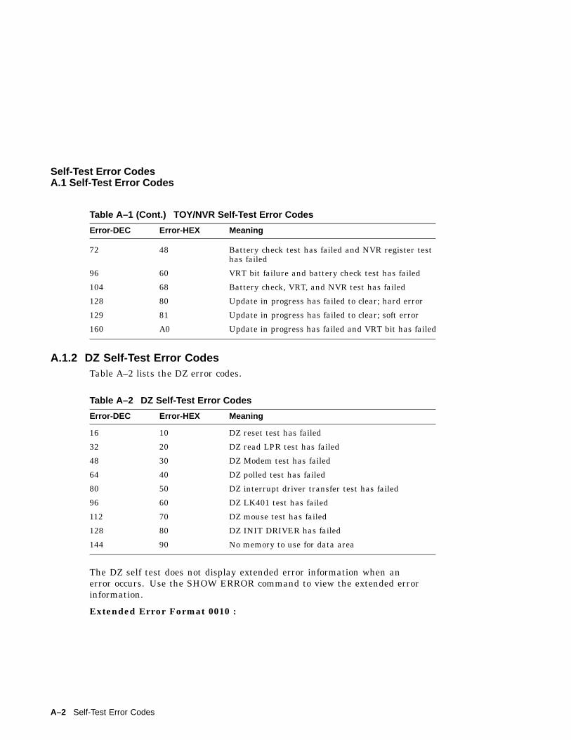
Self-Test Error CodesA.1 Self-Test Error Codes
Table A–1 (Cont.) TOY/NVR Self-Test Error Codes
Error-DEC Error-HEX Meaning
72 48 Battery check test has failed and NVR register testhas failed
96 60 VRT bit failure and battery check test has failed
104 68 Battery check, VRT, and NVR test has failed
128 80 Update in progress has failed to clear; hard error
129 81 Update in progress has failed to clear; soft error
160 A0 Update in progress has failed and VRT bit has failed
A.1.2 DZ Self-Test Error CodesTable A–2 lists the DZ error codes.
Table A–2 DZ Self-Test Error Codes
Error-DEC Error-HEX Meaning
16 10 DZ reset test has failed
32 20 DZ read LPR test has failed
48 30 DZ Modem test has failed
64 40 DZ polled test has failed
80 50 DZ interrupt driver transfer test has failed
96 60 DZ LK401 test has failed
112 70 DZ mouse test has failed
128 80 DZ INIT DRIVER has failed
144 90 No memory to use for data area
The DZ self test does not display extended error information when anerror occurs. Use the SHOW ERROR command to view the extended errorinformation.
Extended Error Format 0010 :
A–2 Self-Test Error Codes
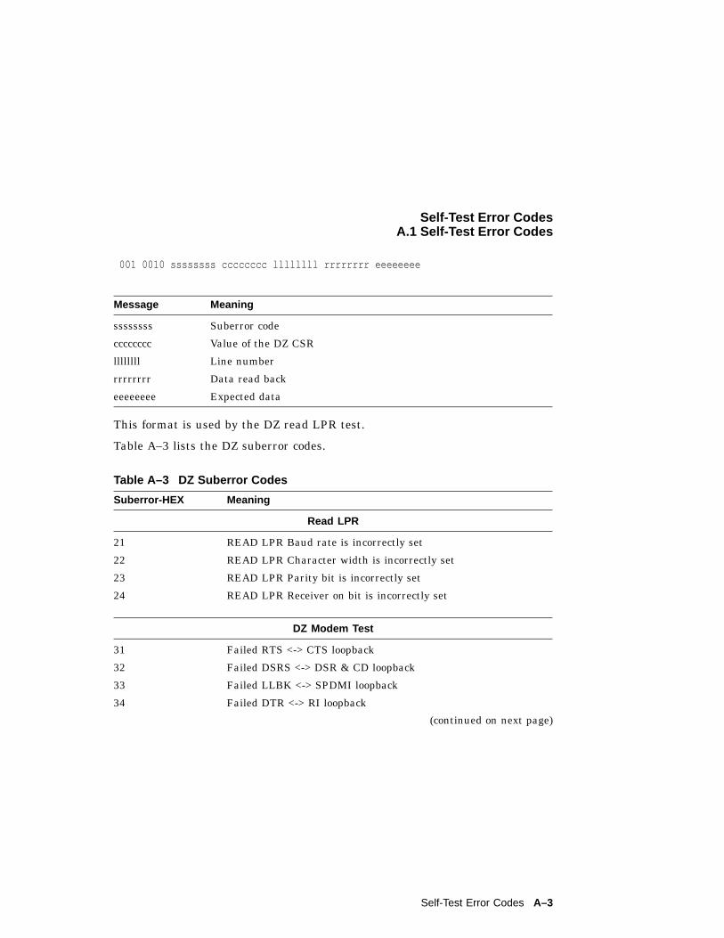
Self-Test Error CodesA.1 Self-Test Error Codes
001 0010 ssssssss cccccccc llllllll rrrrrrrr eeeeeeee
Message Meaning
ssssssss Suberror code
cccccccc Value of the DZ CSR
llllllll Line number
rrrrrrrr Data read back
eeeeeeee Expected data
This format is used by the DZ read LPR test.
Table A–3 lists the DZ suberror codes.
Table A–3 DZ Suberror Codes
Suberror-HEX Meaning
Read LPR
21 READ LPR Baud rate is incorrectly set
22 READ LPR Character width is incorrectly set
23 READ LPR Parity bit is incorrectly set
24 READ LPR Receiver on bit is incorrectly set
DZ Modem Test
31 Failed RTS <-> CTS loopback
32 Failed DSRS <-> DSR & CD loopback
33 Failed LLBK <-> SPDMI loopback
34 Failed DTR <-> RI loopback
(continued on next page)
Self-Test Error Codes A–3
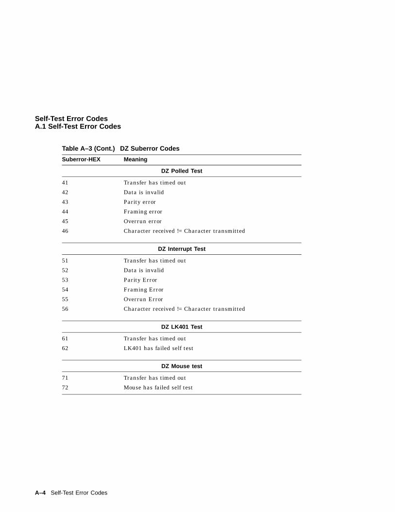
Self-Test Error CodesA.1 Self-Test Error Codes
Table A–3 (Cont.) DZ Suberror Codes
Suberror-HEX Meaning
DZ Polled Test
41 Transfer has timed out
42 Data is invalid
43 Parity error
44 Framing error
45 Overrun error
46 Character received != Character transmitted
DZ Interrupt Test
51 Transfer has timed out
52 Data is invalid
53 Parity Error
54 Framing Error
55 Overrun Error
56 Character received != Character transmitted
DZ LK401 Test
61 Transfer has timed out
62 LK401 has failed self test
DZ Mouse test
71 Transfer has timed out
72 Mouse has failed self test
A–4 Self-Test Error Codes
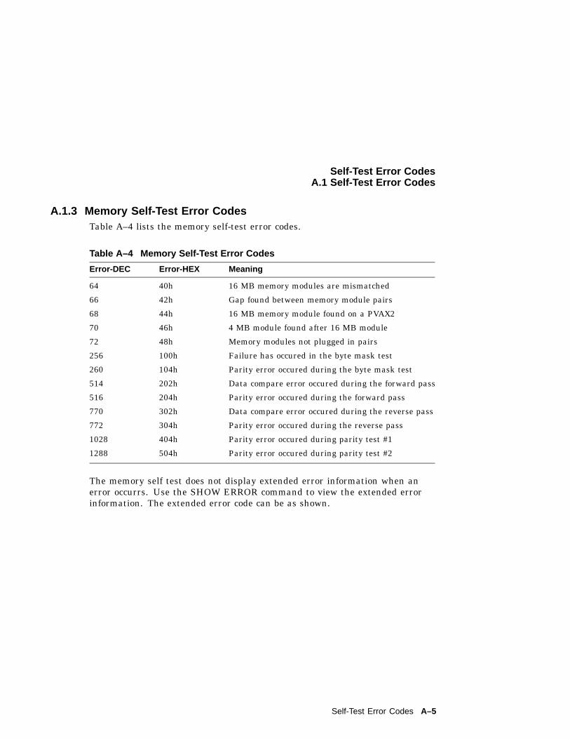
Self-Test Error CodesA.1 Self-Test Error Codes
A.1.3 Memory Self-Test Error CodesTable A–4 lists the memory self-test error codes.
Table A–4 Memory Self-Test Error Codes
Error-DEC Error-HEX Meaning
64 40h 16 MB memory modules are mismatched
66 42h Gap found between memory module pairs
68 44h 16 MB memory module found on a PVAX2
70 46h 4 MB module found after 16 MB module
72 48h Memory modules not plugged in pairs
256 100h Failure has occured in the byte mask test
260 104h Parity error occured during the byte mask test
514 202h Data compare error occured during the forward pass
516 204h Parity error occured during the forward pass
770 302h Data compare error occured during the reverse pass
772 304h Parity error occured during the reverse pass
1028 404h Parity error occured during parity test #1
1288 504h Parity error occured during parity test #2
The memory self test does not display extended error information when anerror occurrs. Use the SHOW ERROR command to view the extended errorinformation. The extended error code can be as shown.
Self-Test Error Codes A–5
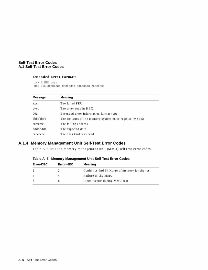
Self-Test Error CodesA.1 Self-Test Error Codes
Extended Error Format:
xxx 4 MEM yyyyxxx 00a bbbbbbbb cccccccc dddddddd eeeeeeee
Message Meaning
xxx The failed FRU
yyyy The error code in HEX
00a Extended error information format type
bbbbbbbb The contents of the memory system error register (MSER)
cccccccc The failing address
dddddddd The expected data
eeeeeeee The data that was read
A.1.4 Memory Management Unit Self-Test Error CodesTable A–5 lists the memory management unit (MMU) self-test error codes.
Table A–5 Memory Management Unit Self-Test Error Codes
Error-DEC Error-HEX Meaning
2 2 Could not find 64 Kbyte of memory for the test
4 4 Failure in the MMU
8 8 Illegal vector during MMU test
A–6 Self-Test Error Codes
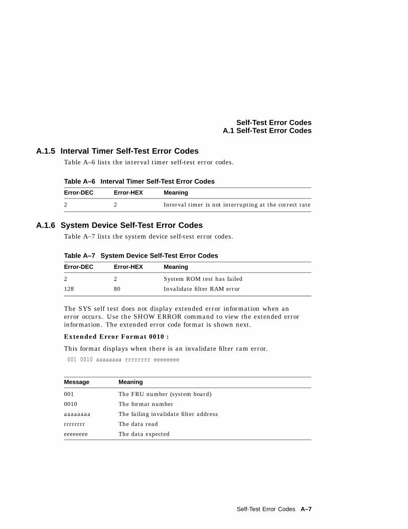
Self-Test Error CodesA.1 Self-Test Error Codes
A.1.5 Interval Timer Self-Test Error CodesTable A–6 lists the interval timer self-test error codes.
Table A–6 Interval Timer Self-Test Error Codes
Error-DEC Error-HEX Meaning
2 2 Interval timer is not interrupting at the correct rate
A.1.6 System Device Self-Test Error CodesTable A–7 lists the system device self-test error codes.
Table A–7 System Device Self-Test Error Codes
Error-DEC Error-HEX Meaning
2 2 System ROM test has failed
128 80 Invalidate filter RAM error
The SYS self test does not display extended error information when anerror occurs. Use the SHOW ERROR command to view the extended errorinformation. The extended error code format is shown next.
Extended Error Format 0010 :
This format displays when there is an invalidate filter ram error.
001 0010 aaaaaaaa rrrrrrrr eeeeeeee
Message Meaning
001 The FRU number (system board)
0010 The format number
aaaaaaaa The failing invalidate filter address
rrrrrrrr The data read
eeeeeeee The data expected
Self-Test Error Codes A–7
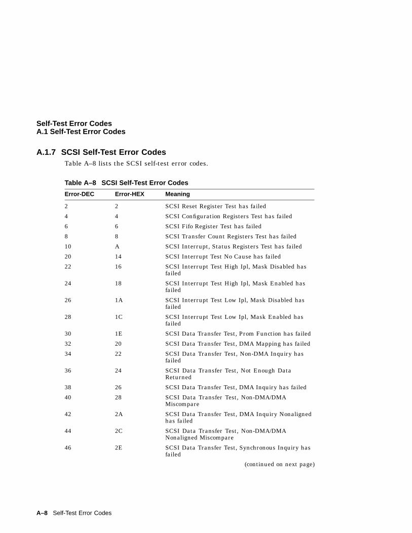
Self-Test Error CodesA.1 Self-Test Error Codes
A.1.7 SCSI Self-Test Error CodesTable A–8 lists the SCSI self-test error codes.
Table A–8 SCSI Self-Test Error Codes
Error-DEC Error-HEX Meaning
2 2 SCSI Reset Register Test has failed
4 4 SCSI Configuration Registers Test has failed
6 6 SCSI Fifo Register Test has failed
8 8 SCSI Transfer Count Registers Test has failed
10 A SCSI Interrupt, Status Registers Test has failed
20 14 SCSI Interrupt Test No Cause has failed
22 16 SCSI Interrupt Test High Ipl, Mask Disabled hasfailed
24 18 SCSI Interrupt Test High Ipl, Mask Enabled hasfailed
26 1A SCSI Interrupt Test Low Ipl, Mask Disabled hasfailed
28 1C SCSI Interrupt Test Low Ipl, Mask Enabled hasfailed
30 1E SCSI Data Transfer Test, Prom Function has failed
32 20 SCSI Data Transfer Test, DMA Mapping has failed
34 22 SCSI Data Transfer Test, Non-DMA Inquiry hasfailed
36 24 SCSI Data Transfer Test, Not Enough DataReturned
38 26 SCSI Data Transfer Test, DMA Inquiry has failed
40 28 SCSI Data Transfer Test, Non-DMA/DMAMiscompare
42 2A SCSI Data Transfer Test, DMA Inquiry Nonalignedhas failed
44 2C SCSI Data Transfer Test, Non-DMA/DMANonaligned Miscompare
46 2E SCSI Data Transfer Test, Synchronous Inquiry hasfailed
(continued on next page)
A–8 Self-Test Error Codes
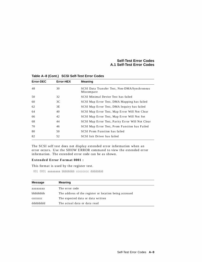
Self-Test Error CodesA.1 Self-Test Error Codes
Table A–8 (Cont.) SCSI Self-Test Error Codes
Error-DEC Error-HEX Meaning
48 30 SCSI Data Transfer Test, Non-DMA/SynchronousMiscompare
50 32 SCSI Minimal Device Test has failed
60 3C SCSI Map Error Test, DMA Mapping has failed
62 3E SCSI Map Error Test, DMA Inquiry has failed
64 40 SCSI Map Error Test, Map Error Will Not Clear
66 42 SCSI Map Error Test, Map Error Will Not Set
68 44 SCSI Map Error Test, Parity Error Will Not Clear
70 46 SCSI Map Error Test, Prom Function has Failed
80 50 SCSI Prom Function has failed
82 52 SCSI Init Driver has failed
The SCSI self test does not display extended error information when anerror occurs. Use the SHOW ERROR command to view the extended errorinformation. The extended error code can be as shown.
Extended Error Format 0001 :
This format is used by the register test.
001 0001 aaaaaaaa bbbbbbbb cccccccc dddddddd
Message Meaning
aaaaaaaa The error code
bbbbbbbb The address of the register or location being accessed
cccccccc The expected data or data written
dddddddd The actual data or data read
Self-Test Error Codes A–9
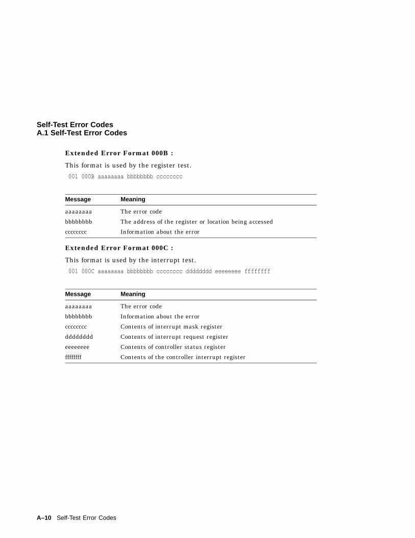
Self-Test Error CodesA.1 Self-Test Error Codes
Extended Error Format 000B :
This format is used by the register test.
001 000B aaaaaaaa bbbbbbbb cccccccc
Message Meaning
aaaaaaaa The error code
bbbbbbbb The address of the register or location being accessed
cccccccc Information about the error
Extended Error Format 000C :
This format is used by the interrupt test.
001 000C aaaaaaaa bbbbbbbb cccccccc dddddddd eeeeeeee ffffffff
Message Meaning
aaaaaaaa The error code
bbbbbbbb Information about the error
cccccccc Contents of interrupt mask register
dddddddd Contents of interrupt request register
eeeeeeee Contents of controller status register
ffffffff Contents of the controller interrupt register
A–10 Self-Test Error Codes
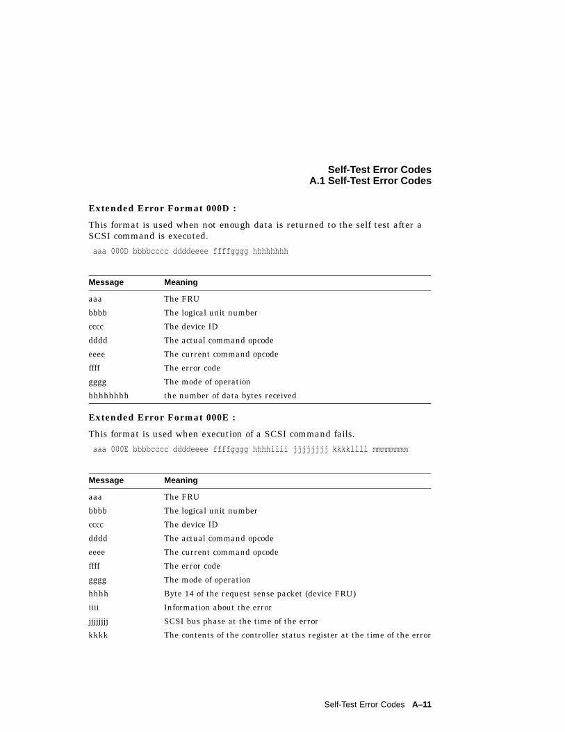
Self-Test Error CodesA.1 Self-Test Error Codes
Extended Error Format 000D :
This format is used when not enough data is returned to the self test after aSCSI command is executed.
aaa 000D bbbbcccc ddddeeee ffffgggg hhhhhhhh
Message Meaning
aaa The FRU
bbbb The logical unit number
cccc The device ID
dddd The actual command opcode
eeee The current command opcode
ffff The error code
gggg The mode of operation
hhhhhhhh the number of data bytes received
Extended Error Format 000E :
This format is used when execution of a SCSI command fails.
aaa 000E bbbbcccc ddddeeee ffffgggg hhhhiiii jjjjjjjj kkkkllll mmmmmmmm
Message Meaning
aaa The FRU
bbbb The logical unit number
cccc The device ID
dddd The actual command opcode
eeee The current command opcode
ffff The error code
gggg The mode of operation
hhhh Byte 14 of the request sense packet (device FRU)
iiii Information about the error
jjjjjjjj SCSI bus phase at the time of the error
kkkk The contents of the controller status register at the time of the error
Self-Test Error Codes A–11
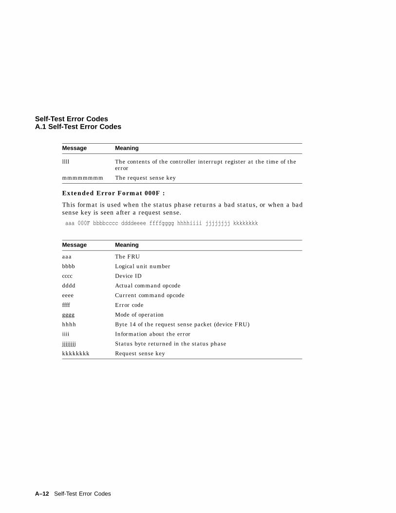
Self-Test Error CodesA.1 Self-Test Error Codes
Message Meaning
llll The contents of the controller interrupt register at the time of theerror
mmmmmmmm The request sense key
Extended Error Format 000F :
This format is used when the status phase returns a bad status, or when a badsense key is seen after a request sense.
aaa 000F bbbbcccc ddddeeee ffffgggg hhhhiiii jjjjjjjj kkkkkkkk
Message Meaning
aaa The FRU
bbbb Logical unit number
cccc Device ID
dddd Actual command opcode
eeee Current command opcode
ffff Error code
gggg Mode of operation
hhhh Byte 14 of the request sense packet (device FRU)
iiii Information about the error
jjjjjjjj Status byte returned in the status phase
kkkkkkkk Request sense key
A–12 Self-Test Error Codes
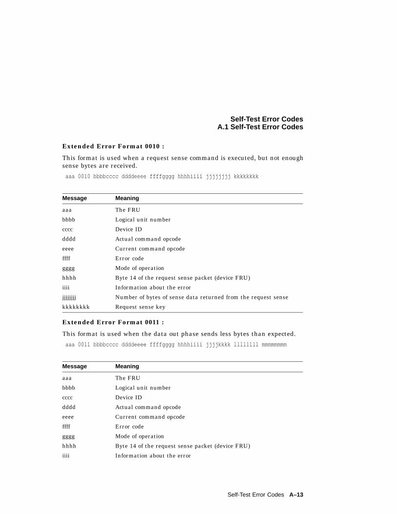
Self-Test Error CodesA.1 Self-Test Error Codes
Extended Error Format 0010 :
This format is used when a request sense command is executed, but not enoughsense bytes are received.
aaa 0010 bbbbcccc ddddeeee ffffgggg hhhhiiii jjjjjjjj kkkkkkkk
Message Meaning
aaa The FRU
bbbb Logical unit number
cccc Device ID
dddd Actual command opcode
eeee Current command opcode
ffff Error code
gggg Mode of operation
hhhh Byte 14 of the request sense packet (device FRU)
iiii Information about the error
jjjjjjjj Number of bytes of sense data returned from the request sense
kkkkkkkk Request sense key
Extended Error Format 0011 :
This format is used when the data out phase sends less bytes than expected.
aaa 0011 bbbbcccc ddddeeee ffffgggg hhhhiiii jjjjkkkk llllllll mmmmmmmm
Message Meaning
aaa The FRU
bbbb Logical unit number
cccc Device ID
dddd Actual command opcode
eeee Current command opcode
ffff Error code
gggg Mode of operation
hhhh Byte 14 of the request sense packet (device FRU)
iiii Information about the error
Self-Test Error Codes A–13
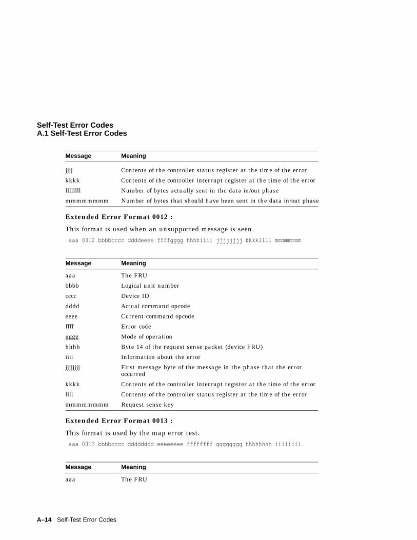
Self-Test Error CodesA.1 Self-Test Error Codes
Message Meaning
jjjj Contents of the controller status register at the time of the error
kkkk Contents of the controller interrupt register at the time of the error
llllllll Number of bytes actually sent in the data in/out phase
mmmmmmmm Number of bytes that should have been sent in the data in/out phase
Extended Error Format 0012 :
This format is used when an unsupported message is seen.
aaa 0012 bbbbcccc ddddeeee ffffgggg hhhhiiii jjjjjjjj kkkkllll mmmmmmmm
Message Meaning
aaa The FRU
bbbb Logical unit number
cccc Device ID
dddd Actual command opcode
eeee Current command opcode
ffff Error code
gggg Mode of operation
hhhh Byte 14 of the request sense packet (device FRU)
iiii Information about the error
jjjjjjjj First message byte of the message in the phase that the erroroccurred
kkkk Contents of the controller interrupt register at the time of the error
llll Contents of the controller status register at the time of the error
mmmmmmmm Request sense key
Extended Error Format 0013 :
This format is used by the map error test.
aaa 0013 bbbbcccc dddddddd eeeeeeee ffffffff gggggggg hhhhhhhh iiiiiiii
Message Meaning
aaa The FRU
A–14 Self-Test Error Codes
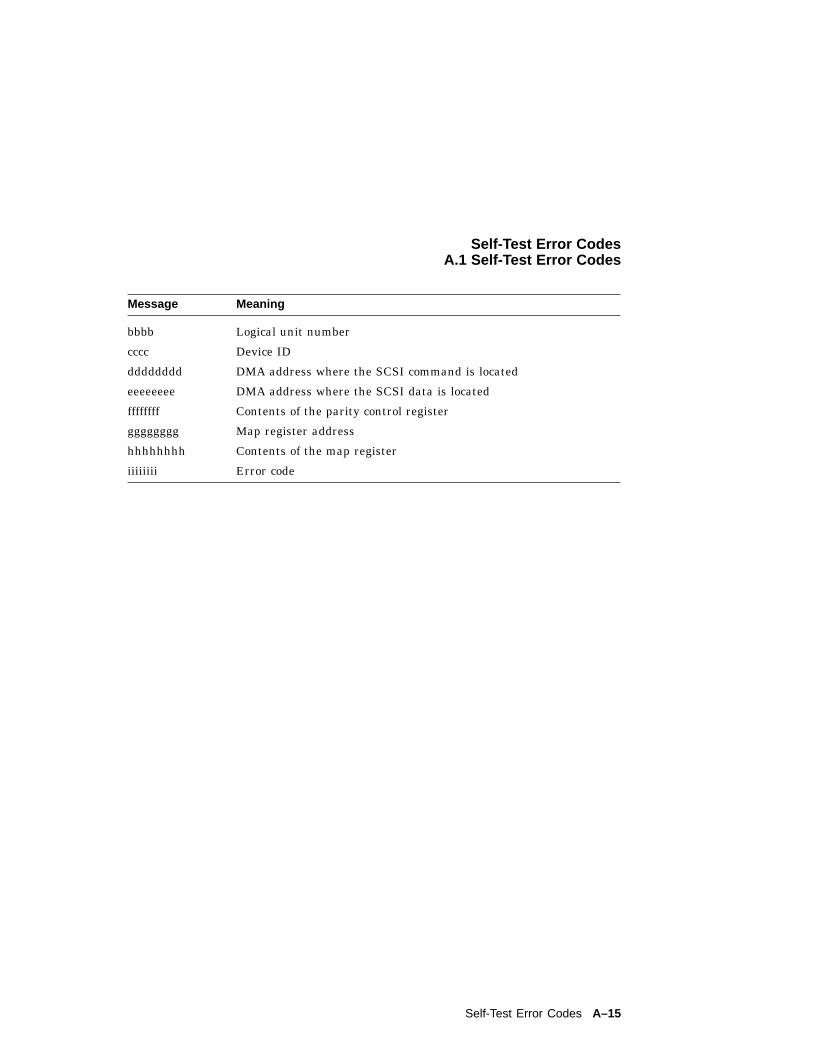
Self-Test Error CodesA.1 Self-Test Error Codes
Message Meaning
bbbb Logical unit number
cccc Device ID
dddddddd DMA address where the SCSI command is located
eeeeeeee DMA address where the SCSI data is located
ffffffff Contents of the parity control register
gggggggg Map register address
hhhhhhhh Contents of the map register
iiiiiiii Error code
Self-Test Error Codes A–15
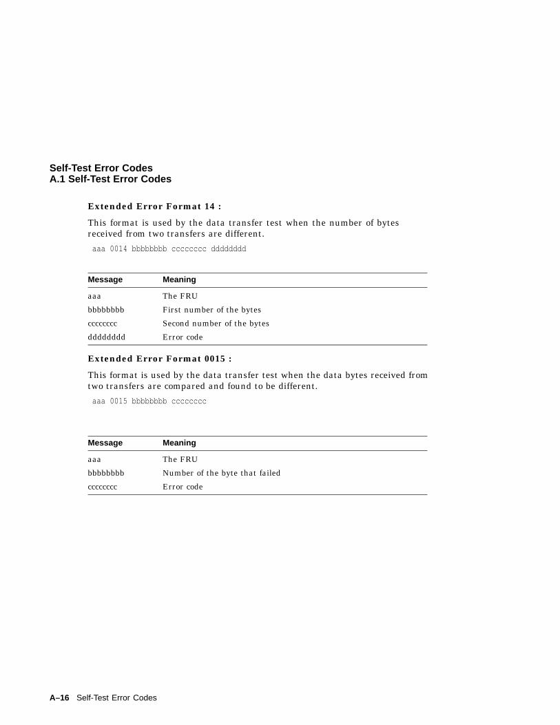
Self-Test Error CodesA.1 Self-Test Error Codes
Extended Error Format 14 :
This format is used by the data transfer test when the number of bytesreceived from two transfers are different.
aaa 0014 bbbbbbbb cccccccc dddddddd
Message Meaning
aaa The FRU
bbbbbbbb First number of the bytes
cccccccc Second number of the bytes
dddddddd Error code
Extended Error Format 0015 :
This format is used by the data transfer test when the data bytes received fromtwo transfers are compared and found to be different.
aaa 0015 bbbbbbbb cccccccc
Message Meaning
aaa The FRU
bbbbbbbb Number of the byte that failed
cccccccc Error code
A–16 Self-Test Error Codes
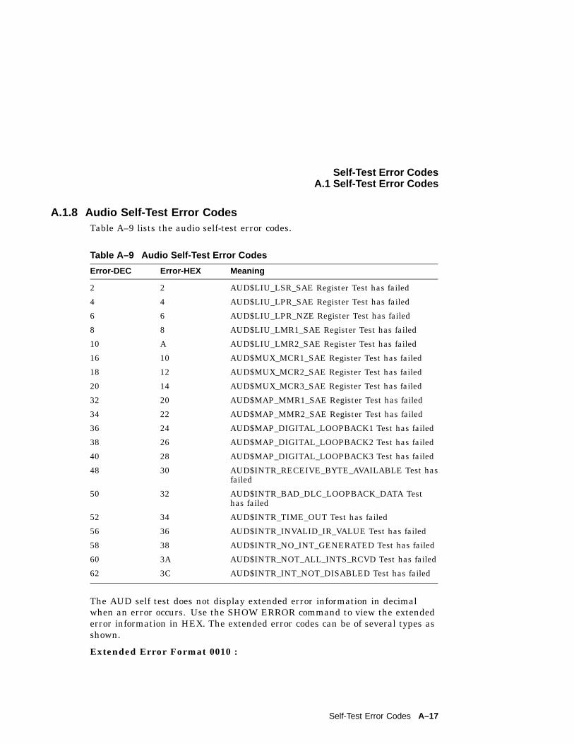
Self-Test Error CodesA.1 Self-Test Error Codes
A.1.8 Audio Self-Test Error CodesTable A–9 lists the audio self-test error codes.
Table A–9 Audio Self-Test Error Codes
Error-DEC Error-HEX Meaning
2 2 AUD$LIU_LSR_SAE Register Test has failed
4 4 AUD$LIU_LPR_SAE Register Test has failed
6 6 AUD$LIU_LPR_NZE Register Test has failed
8 8 AUD$LIU_LMR1_SAE Register Test has failed
10 A AUD$LIU_LMR2_SAE Register Test has failed
16 10 AUD$MUX_MCR1_SAE Register Test has failed
18 12 AUD$MUX_MCR2_SAE Register Test has failed
20 14 AUD$MUX_MCR3_SAE Register Test has failed
32 20 AUD$MAP_MMR1_SAE Register Test has failed
34 22 AUD$MAP_MMR2_SAE Register Test has failed
36 24 AUD$MAP_DIGITAL_LOOPBACK1 Test has failed
38 26 AUD$MAP_DIGITAL_LOOPBACK2 Test has failed
40 28 AUD$MAP_DIGITAL_LOOPBACK3 Test has failed
48 30 AUD$INTR_RECEIVE_BYTE_AVAILABLE Test hasfailed
50 32 AUD$INTR_BAD_DLC_LOOPBACK_DATA Testhas failed
52 34 AUD$INTR_TIME_OUT Test has failed
56 36 AUD$INTR_INVALID_IR_VALUE Test has failed
58 38 AUD$INTR_NO_INT_GENERATED Test has failed
60 3A AUD$INTR_NOT_ALL_INTS_RCVD Test has failed
62 3C AUD$INTR_INT_NOT_DISABLED Test has failed
The AUD self test does not display extended error information in decimalwhen an error occurs. Use the SHOW ERROR command to view the extendederror information in HEX. The extended error codes can be of several types asshown.
Extended Error Format 0010 :
Self-Test Error Codes A–17
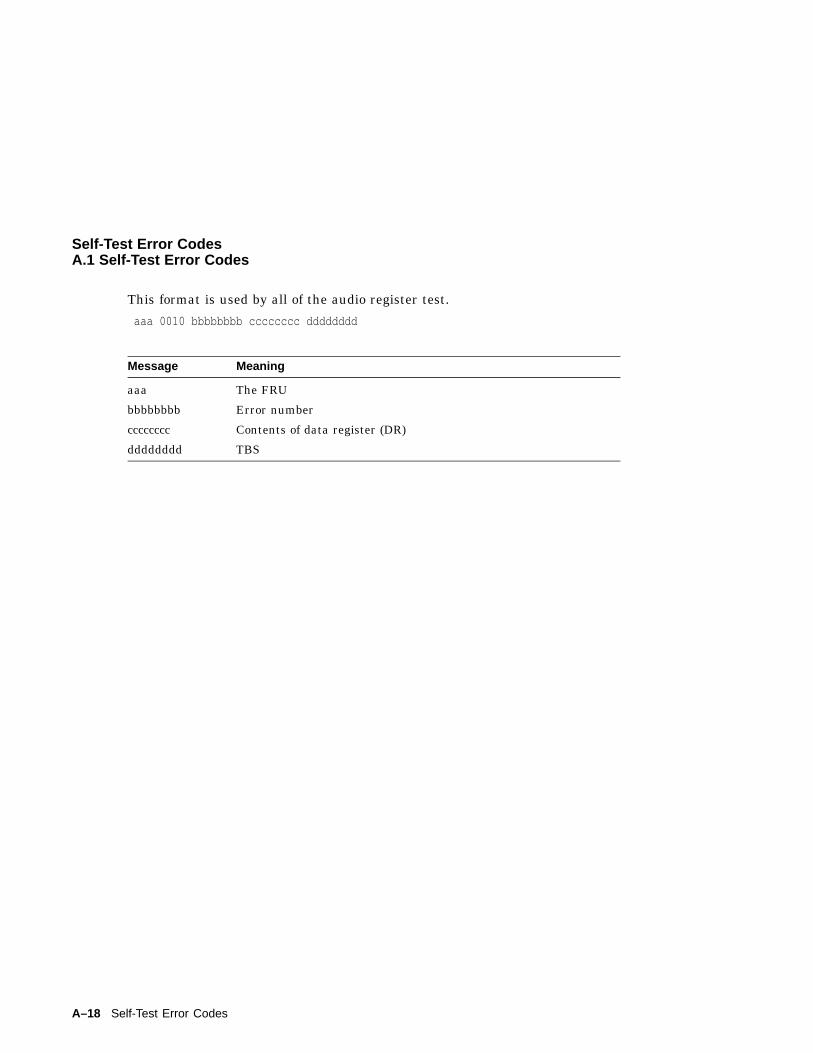
Self-Test Error CodesA.1 Self-Test Error Codes
This format is used by all of the audio register test.
aaa 0010 bbbbbbbb cccccccc dddddddd
Message Meaning
aaa The FRU
bbbbbbbb Error number
cccccccc Contents of data register (DR)
dddddddd TBS
A–18 Self-Test Error Codes
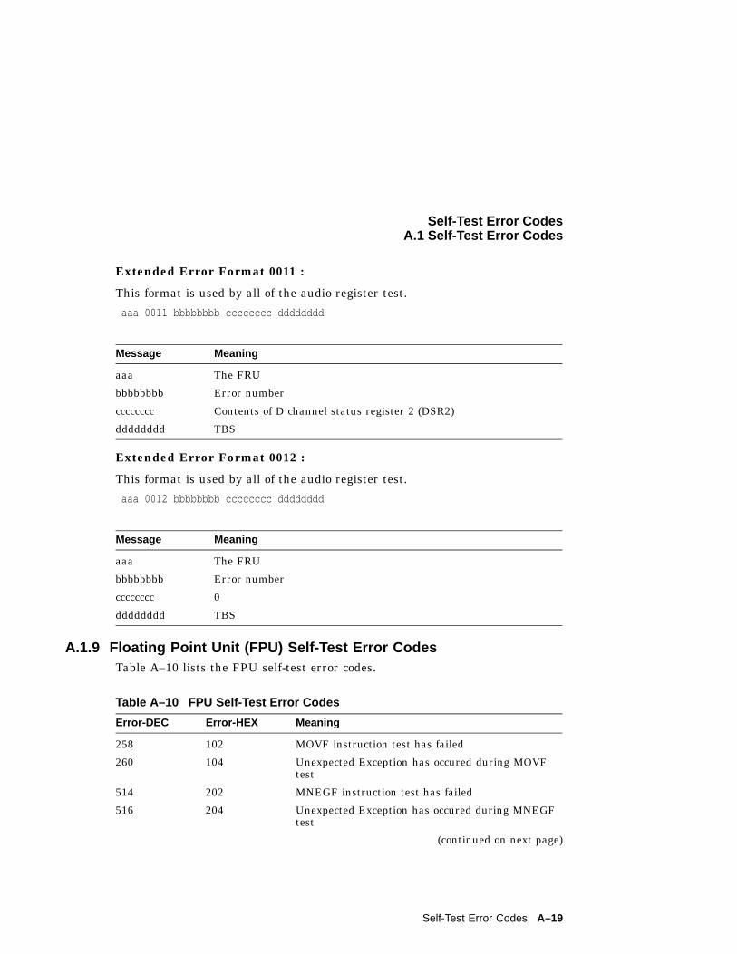
Self-Test Error CodesA.1 Self-Test Error Codes
Extended Error Format 0011 :
This format is used by all of the audio register test.
aaa 0011 bbbbbbbb cccccccc dddddddd
Message Meaning
aaa The FRU
bbbbbbbb Error number
cccccccc Contents of D channel status register 2 (DSR2)
dddddddd TBS
Extended Error Format 0012 :
This format is used by all of the audio register test.
aaa 0012 bbbbbbbb cccccccc dddddddd
Message Meaning
aaa The FRU
bbbbbbbb Error number
cccccccc 0
dddddddd TBS
A.1.9 Floating Point Unit (FPU) Self-Test Error CodesTable A–10 lists the FPU self-test error codes.
Table A–10 FPU Self-Test Error Codes
Error-DEC Error-HEX Meaning
258 102 MOVF instruction test has failed
260 104 Unexpected Exception has occured during MOVFtest
514 202 MNEGF instruction test has failed
516 204 Unexpected Exception has occured during MNEGFtest
(continued on next page)
Self-Test Error Codes A–19
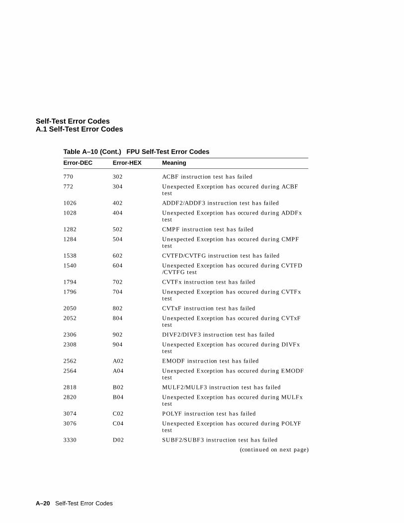
Self-Test Error CodesA.1 Self-Test Error Codes
Table A–10 (Cont.) FPU Self-Test Error Codes
Error-DEC Error-HEX Meaning
770 302 ACBF instruction test has failed
772 304 Unexpected Exception has occured during ACBFtest
1026 402 ADDF2/ADDF3 instruction test has failed
1028 404 Unexpected Exception has occured during ADDFxtest
1282 502 CMPF instruction test has failed
1284 504 Unexpected Exception has occured during CMPFtest
1538 602 CVTFD/CVTFG instruction test has failed
1540 604 Unexpected Exception has occured during CVTFD/CVTFG test
1794 702 CVTFx instruction test has failed
1796 704 Unexpected Exception has occured during CVTFxtest
2050 802 CVTxF instruction test has failed
2052 804 Unexpected Exception has occured during CVTxFtest
2306 902 DIVF2/DIVF3 instruction test has failed
2308 904 Unexpected Exception has occured during DIVFxtest
2562 A02 EMODF instruction test has failed
2564 A04 Unexpected Exception has occured during EMODFtest
2818 B02 MULF2/MULF3 instruction test has failed
2820 B04 Unexpected Exception has occured during MULFxtest
3074 C02 POLYF instruction test has failed
3076 C04 Unexpected Exception has occured during POLYFtest
3330 D02 SUBF2/SUBF3 instruction test has failed
(continued on next page)
A–20 Self-Test Error Codes
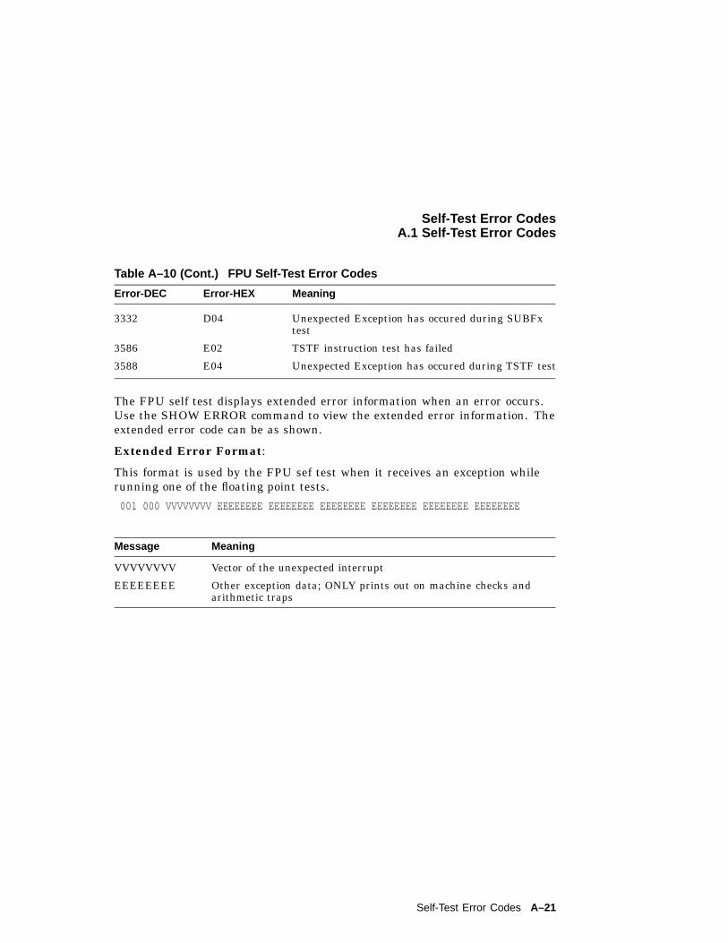
Self-Test Error CodesA.1 Self-Test Error Codes
Table A–10 (Cont.) FPU Self-Test Error Codes
Error-DEC Error-HEX Meaning
3332 D04 Unexpected Exception has occured during SUBFxtest
3586 E02 TSTF instruction test has failed
3588 E04 Unexpected Exception has occured during TSTF test
The FPU self test displays extended error information when an error occurs.Use the SHOW ERROR command to view the extended error information. Theextended error code can be as shown.
Extended Error Format:
This format is used by the FPU sef test when it receives an exception whilerunning one of the floating point tests.
001 000 VVVVVVVV EEEEEEEE EEEEEEEE EEEEEEEE EEEEEEEE EEEEEEEE EEEEEEEE
Message Meaning
VVVVVVVV Vector of the unexpected interrupt
EEEEEEEE Other exception data; ONLY prints out on machine checks andarithmetic traps
Self-Test Error Codes A–21
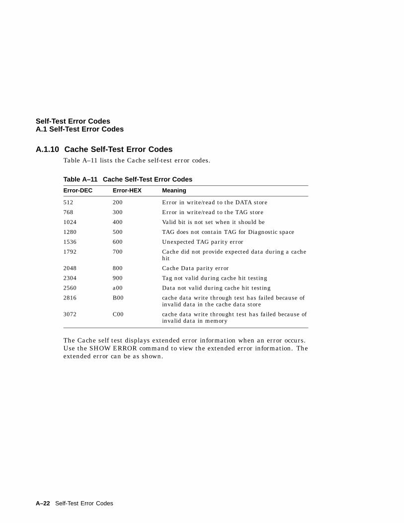
Self-Test Error CodesA.1 Self-Test Error Codes
A.1.10 Cache Self-Test Error CodesTable A–11 lists the Cache self-test error codes.
Table A–11 Cache Self-Test Error Codes
Error-DEC Error-HEX Meaning
512 200 Error in write/read to the DATA store
768 300 Error in write/read to the TAG store
1024 400 Valid bit is not set when it should be
1280 500 TAG does not contain TAG for Diagnostic space
1536 600 Unexpected TAG parity error
1792 700 Cache did not provide expected data during a cachehit
2048 800 Cache Data parity error
2304 900 Tag not valid during cache hit testing
2560 a00 Data not valid during cache hit testing
2816 B00 cache data write through test has failed because ofinvalid data in the cache data store
3072 C00 cache data write throught test has failed because ofinvalid data in memory
The Cache self test displays extended error information when an error occurs.Use the SHOW ERROR command to view the extended error information. Theextended error can be as shown.
A–22 Self-Test Error Codes
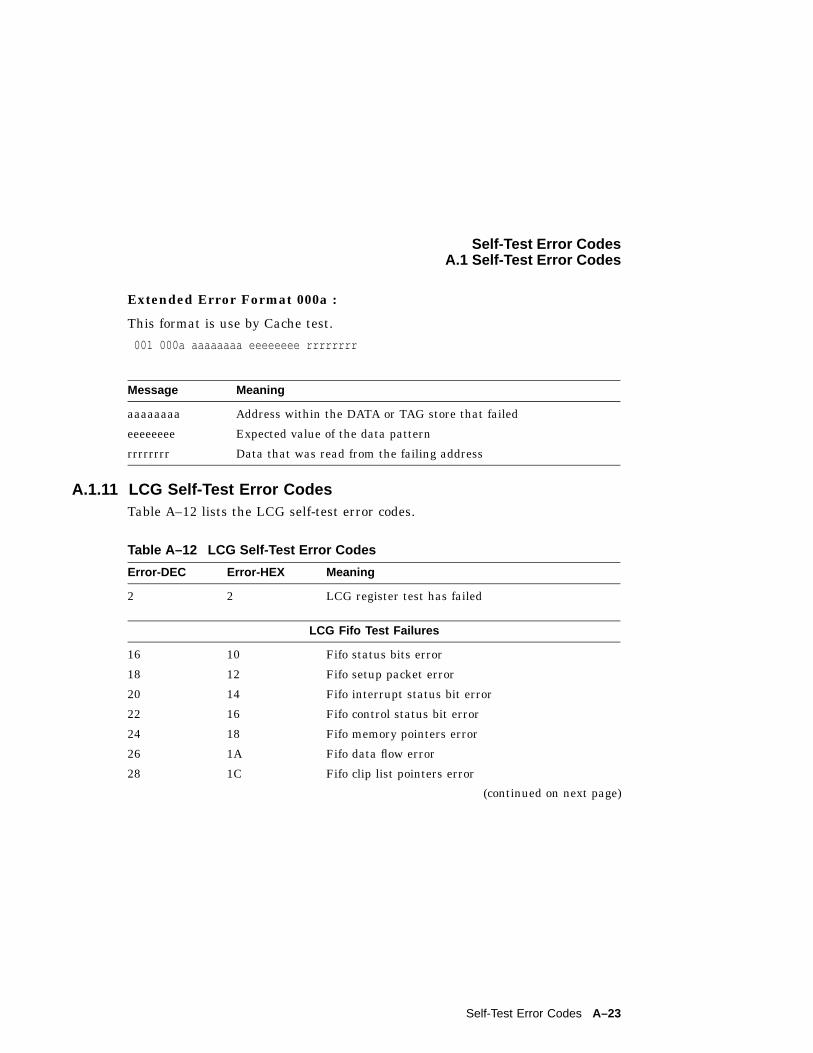
Self-Test Error CodesA.1 Self-Test Error Codes
Extended Error Format 000a :
This format is use by Cache test.
001 000a aaaaaaaa eeeeeeee rrrrrrrr
Message Meaning
aaaaaaaa Address within the DATA or TAG store that failed
eeeeeeee Expected value of the data pattern
rrrrrrrr Data that was read from the failing address
A.1.11 LCG Self-Test Error CodesTable A–12 lists the LCG self-test error codes.
Table A–12 LCG Self-Test Error Codes
Error-DEC Error-HEX Meaning
2 2 LCG register test has failed
LCG Fifo Test Failures
16 10 Fifo status bits error
18 12 Fifo setup packet error
20 14 Fifo interrupt status bit error
22 16 Fifo control status bit error
24 18 Fifo memory pointers error
26 1A Fifo data flow error
28 1C Fifo clip list pointers error
(continued on next page)
Self-Test Error Codes A–23
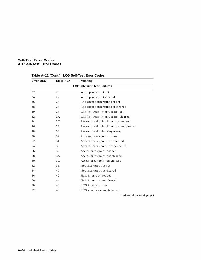
Self-Test Error CodesA.1 Self-Test Error Codes
Table A–12 (Cont.) LCG Self-Test Error Codes
Error-DEC Error-HEX Meaning
LCG Interrupt Test Failures
32 20 Write protect not set
34 22 Write protect not cleared
36 24 Bad opcode interrupt not set
38 26 Bad opcode interrupt not cleared
40 28 Clip list wrap interrupt not set
42 2A Clip list wrap interrupt not cleared
44 2C Packet breakpoint interrupt not set
46 2E Packet breakpoint interrupt not cleared
48 30 Packet breakpoint single step
50 32 Address breakpoint not set
52 34 Address breakpoint not cleared
54 36 Address breakpoint not cancelled
56 38 Access breakpoint not set
58 3A Access breakpoint not cleared
60 3C Access breakpoint single step
62 3E Nop interrupt not set
64 40 Nop interrupt not cleared
66 42 Halt interrupt not set
68 44 Halt interrupt not cleared
70 46 LCG interrupt line
72 48 LCG memory error interrupt
(continued on next page)
A–24 Self-Test Error Codes
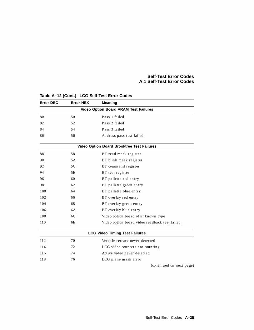
Self-Test Error CodesA.1 Self-Test Error Codes
Table A–12 (Cont.) LCG Self-Test Error Codes
Error-DEC Error-HEX Meaning
Video Option Board VRAM Test Failures
80 50 Pass 1 failed
82 52 Pass 2 failed
84 54 Pass 3 failed
86 56 Address pass test failed
Video Option Board Brooktree Test Failures
88 58 BT read mask register
90 5A BT blink mask register
92 5C BT command register
94 5E BT test register
96 60 BT pallette red entry
98 62 BT pallette green entry
100 64 BT pallette blue entry
102 66 BT overlay red entry
104 68 BT overlay green entry
106 6A BT overlay blue entry
108 6C Video option board of unknown type
110 6E Video option board video readback test failed
LCG Video Timing Test Failures
112 70 Verticle retrace never detected
114 72 LCG video counters not counting
116 74 Active video never detected
118 76 LCG plane mask error
(continued on next page)
Self-Test Error Codes A–25
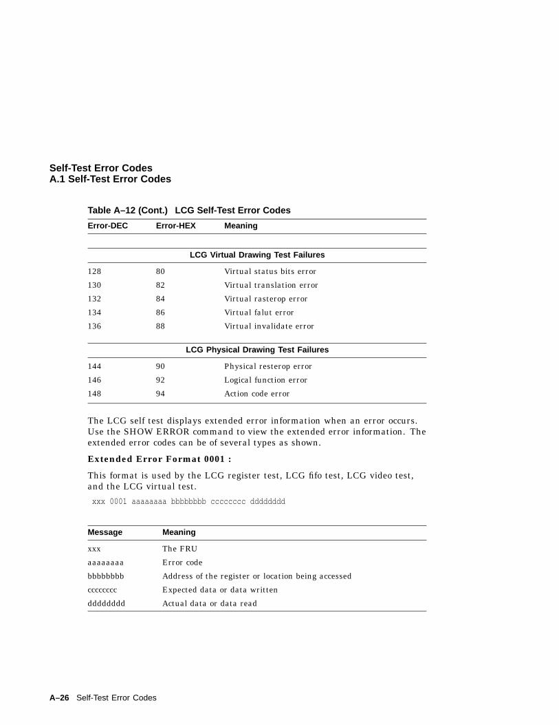
Self-Test Error CodesA.1 Self-Test Error Codes
Table A–12 (Cont.) LCG Self-Test Error Codes
Error-DEC Error-HEX Meaning
LCG Virtual Drawing Test Failures
128 80 Virtual status bits error
130 82 Virtual translation error
132 84 Virtual rasterop error
134 86 Virtual falut error
136 88 Virtual invalidate error
LCG Physical Drawing Test Failures
144 90 Physical resterop error
146 92 Logical function error
148 94 Action code error
The LCG self test displays extended error information when an error occurs.Use the SHOW ERROR command to view the extended error information. Theextended error codes can be of several types as shown.
Extended Error Format 0001 :
This format is used by the LCG register test, LCG fifo test, LCG video test,and the LCG virtual test.
xxx 0001 aaaaaaaa bbbbbbbb cccccccc dddddddd
Message Meaning
xxx The FRU
aaaaaaaa Error code
bbbbbbbb Address of the register or location being accessed
cccccccc Expected data or data written
dddddddd Actual data or data read
A–26 Self-Test Error Codes
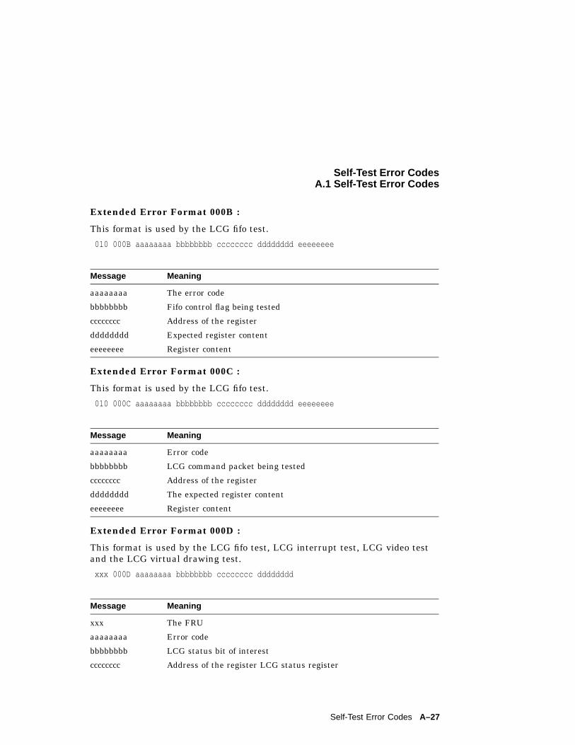
Self-Test Error CodesA.1 Self-Test Error Codes
Extended Error Format 000B :
This format is used by the LCG fifo test.
010 000B aaaaaaaa bbbbbbbb cccccccc dddddddd eeeeeeee
Message Meaning
aaaaaaaa The error code
bbbbbbbb Fifo control flag being tested
cccccccc Address of the register
dddddddd Expected register content
eeeeeeee Register content
Extended Error Format 000C :
This format is used by the LCG fifo test.
010 000C aaaaaaaa bbbbbbbb cccccccc dddddddd eeeeeeee
Message Meaning
aaaaaaaa Error code
bbbbbbbb LCG command packet being tested
cccccccc Address of the register
dddddddd The expected register content
eeeeeeee Register content
Extended Error Format 000D :
This format is used by the LCG fifo test, LCG interrupt test, LCG video testand the LCG virtual drawing test.
xxx 000D aaaaaaaa bbbbbbbb cccccccc dddddddd
Message Meaning
xxx The FRU
aaaaaaaa Error code
bbbbbbbb LCG status bit of interest
cccccccc Address of the register LCG status register
Self-Test Error Codes A–27
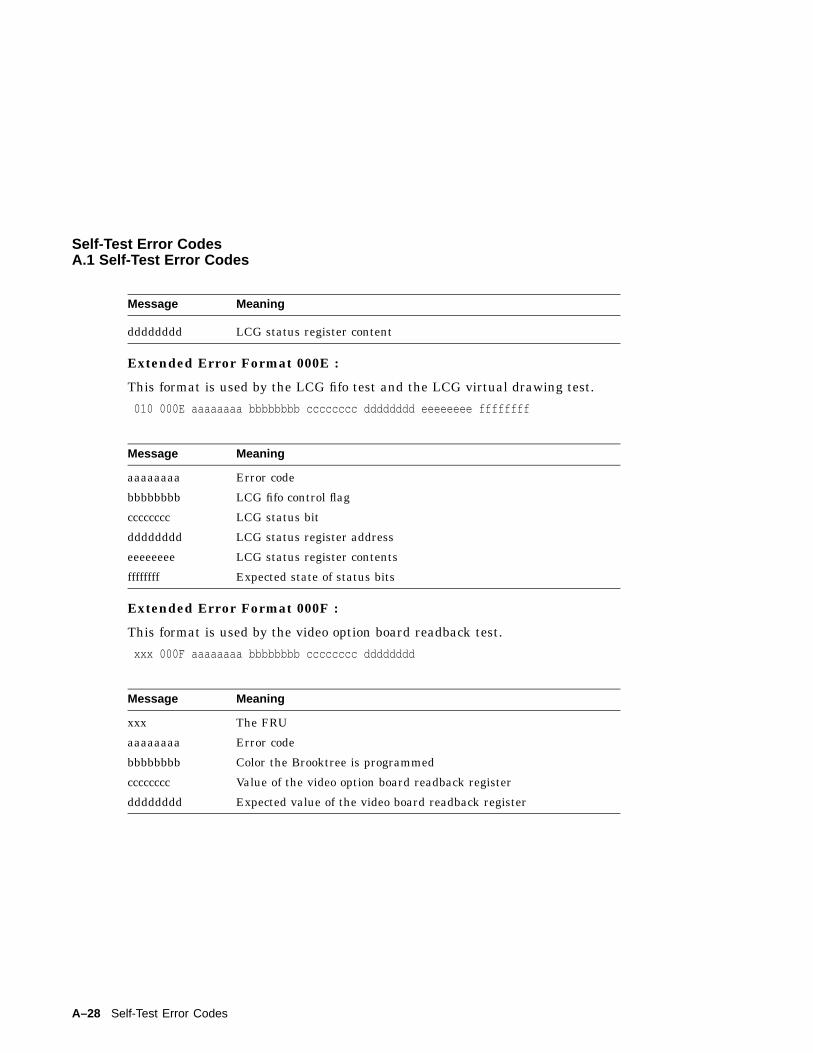
Self-Test Error CodesA.1 Self-Test Error Codes
Message Meaning
dddddddd LCG status register content
Extended Error Format 000E :
This format is used by the LCG fifo test and the LCG virtual drawing test.
010 000E aaaaaaaa bbbbbbbb cccccccc dddddddd eeeeeeee ffffffff
Message Meaning
aaaaaaaa Error code
bbbbbbbb LCG fifo control flag
cccccccc LCG status bit
dddddddd LCG status register address
eeeeeeee LCG status register contents
ffffffff Expected state of status bits
Extended Error Format 000F :
This format is used by the video option board readback test.
xxx 000F aaaaaaaa bbbbbbbb cccccccc dddddddd
Message Meaning
xxx The FRU
aaaaaaaa Error code
bbbbbbbb Color the Brooktree is programmed
cccccccc Value of the video option board readback register
dddddddd Expected value of the video board readback register
A–28 Self-Test Error Codes
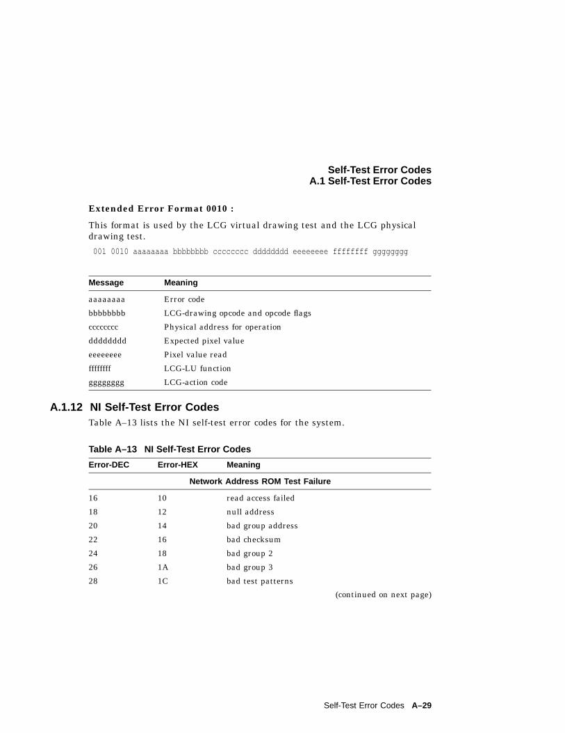
Self-Test Error CodesA.1 Self-Test Error Codes
Extended Error Format 0010 :
This format is used by the LCG virtual drawing test and the LCG physicaldrawing test.
001 0010 aaaaaaaa bbbbbbbb cccccccc dddddddd eeeeeeee ffffffff gggggggg
Message Meaning
aaaaaaaa Error code
bbbbbbbb LCG-drawing opcode and opcode flags
cccccccc Physical address for operation
dddddddd Expected pixel value
eeeeeeee Pixel value read
ffffffff LCG-LU function
gggggggg LCG-action code
A.1.12 NI Self-Test Error CodesTable A–13 lists the NI self-test error codes for the system.
Table A–13 NI Self-Test Error Codes
Error-DEC Error-HEX Meaning
Network Address ROM Test Failure
16 10 read access failed
18 12 null address
20 14 bad group address
22 16 bad checksum
24 18 bad group 2
26 1A bad group 3
28 1C bad test patterns
(continued on next page)
Self-Test Error Codes A–29
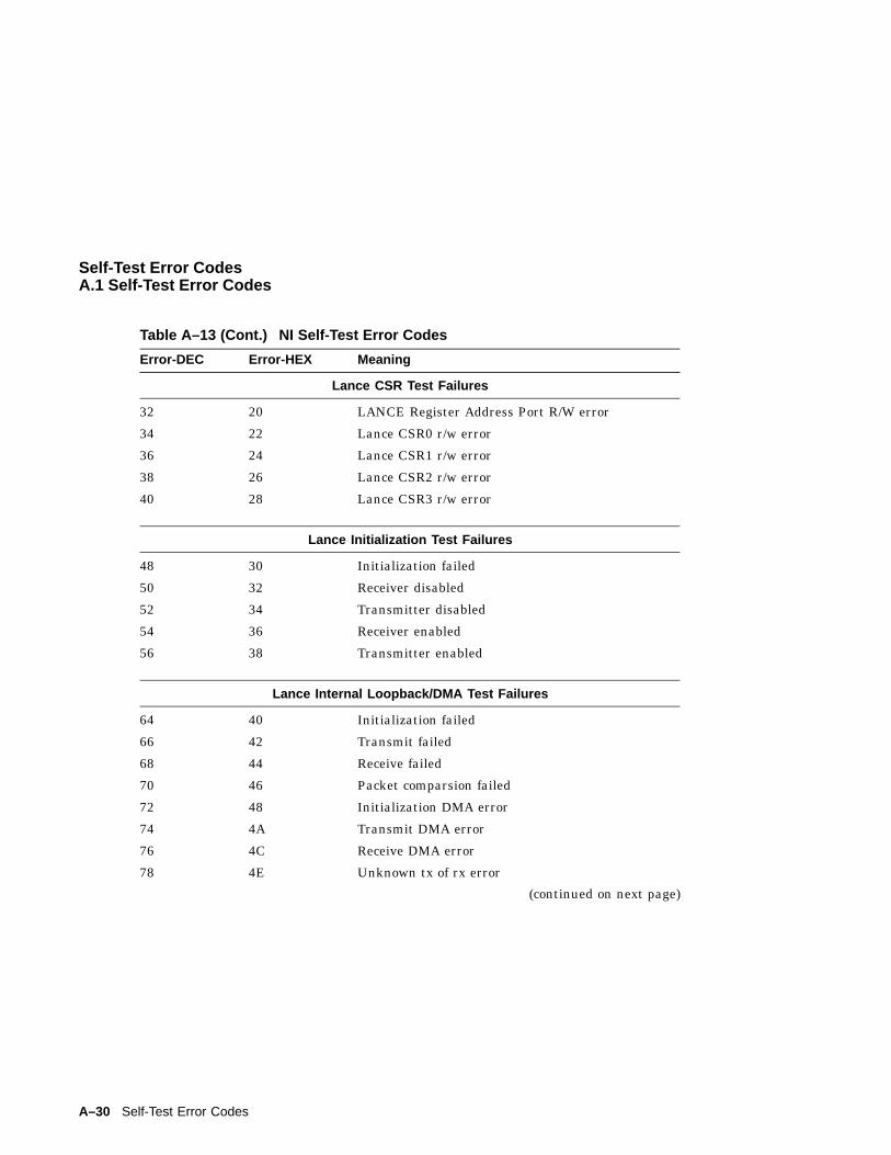
Self-Test Error CodesA.1 Self-Test Error Codes
Table A–13 (Cont.) NI Self-Test Error Codes
Error-DEC Error-HEX Meaning
Lance CSR Test Failures
32 20 LANCE Register Address Port R/W error
34 22 Lance CSR0 r/w error
36 24 Lance CSR1 r/w error
38 26 Lance CSR2 r/w error
40 28 Lance CSR3 r/w error
Lance Initialization Test Failures
48 30 Initialization failed
50 32 Receiver disabled
52 34 Transmitter disabled
54 36 Receiver enabled
56 38 Transmitter enabled
Lance Internal Loopback/DMA Test Failures
64 40 Initialization failed
66 42 Transmit failed
68 44 Receive failed
70 46 Packet comparsion failed
72 48 Initialization DMA error
74 4A Transmit DMA error
76 4C Receive DMA error
78 4E Unknown tx of rx error
(continued on next page)
A–30 Self-Test Error Codes
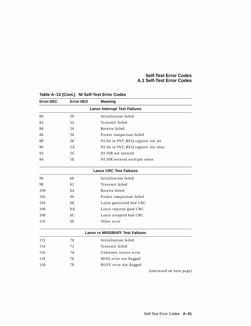
Self-Test Error CodesA.1 Self-Test Error Codes
Table A–13 (Cont.) NI Self-Test Error Codes
Error-DEC Error-HEX Meaning
Lance Interrupt Test Failures
80 50 Initialization failed
82 52 Transmit failed
84 54 Receive failed
86 56 Packet comparison failed
88 58 NI bit in INT_REQ register not set
90 5A NI bit in INT_REQ register not clear
92 5C NI ISR not entered
94 5E NI ISR entered multiple times
Lance CRC Test Failures
96 60 Initialization failed
98 62 Transmit failed
100 64 Receive failed
102 66 Packet comparison failed
104 68 Lance generated bad CRC
106 6A Lance rejected good CRC
108 6C Lance accepted bad CRC
110 6E Other error
Lance rx MISS/BUFF Test Failures
112 70 Initialization failed
114 72 Transmit failed
116 74 Unknown receive error
118 76 MISS error not flagged
120 78 BUFF error not flagged
(continued on next page)
Self-Test Error Codes A–31
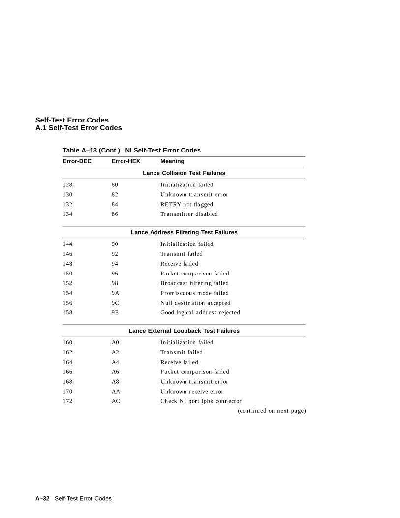
Self-Test Error CodesA.1 Self-Test Error Codes
Table A–13 (Cont.) NI Self-Test Error Codes
Error-DEC Error-HEX Meaning
Lance Collision Test Failures
128 80 Initialization failed
130 82 Unknown transmit error
132 84 RETRY not flagged
134 86 Transmitter disabled
Lance Address Filtering Test Failures
144 90 Initialization failed
146 92 Transmit failed
148 94 Receive failed
150 96 Packet comparison failed
152 98 Broadcast filtering failed
154 9A Promiscuous mode failed
156 9C Null destination accepted
158 9E Good logical address rejected
Lance External Loopback Test Failures
160 A0 Initialization failed
162 A2 Transmit failed
164 A4 Receive failed
166 A6 Packet comparison failed
168 A8 Unknown transmit error
170 AA Unknown receive error
172 AC Check NI port lpbk connector
(continued on next page)
A–32 Self-Test Error Codes
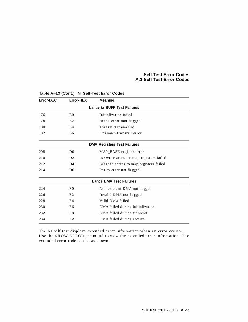
Self-Test Error CodesA.1 Self-Test Error Codes
Table A–13 (Cont.) NI Self-Test Error Codes
Error-DEC Error-HEX Meaning
Lance tx BUFF Test Failures
176 B0 Initialization failed
178 B2 BUFF error mot flagged
180 B4 Transmitter enabled
182 B6 Unknown transmit error
DMA Registers Test Failures
208 D0 MAP_BASE register error
210 D2 I/O write access to map registers failed
212 D4 I/O read access to map registers failed
214 D6 Parity error not flagged
Lance DMA Test Failures
224 E0 Non-existant DMA not flagged
226 E2 Invalid DMA not flagged
228 E4 Valid DMA failed
230 E6 DMA failed during initialization
232 E8 DMA failed during transmit
234 EA DMA failed during receive
The NI self test displays extended error information when an error occurs.Use the SHOW ERROR command to view the extended error information. Theextended error code can be as shown.
Self-Test Error Codes A–33
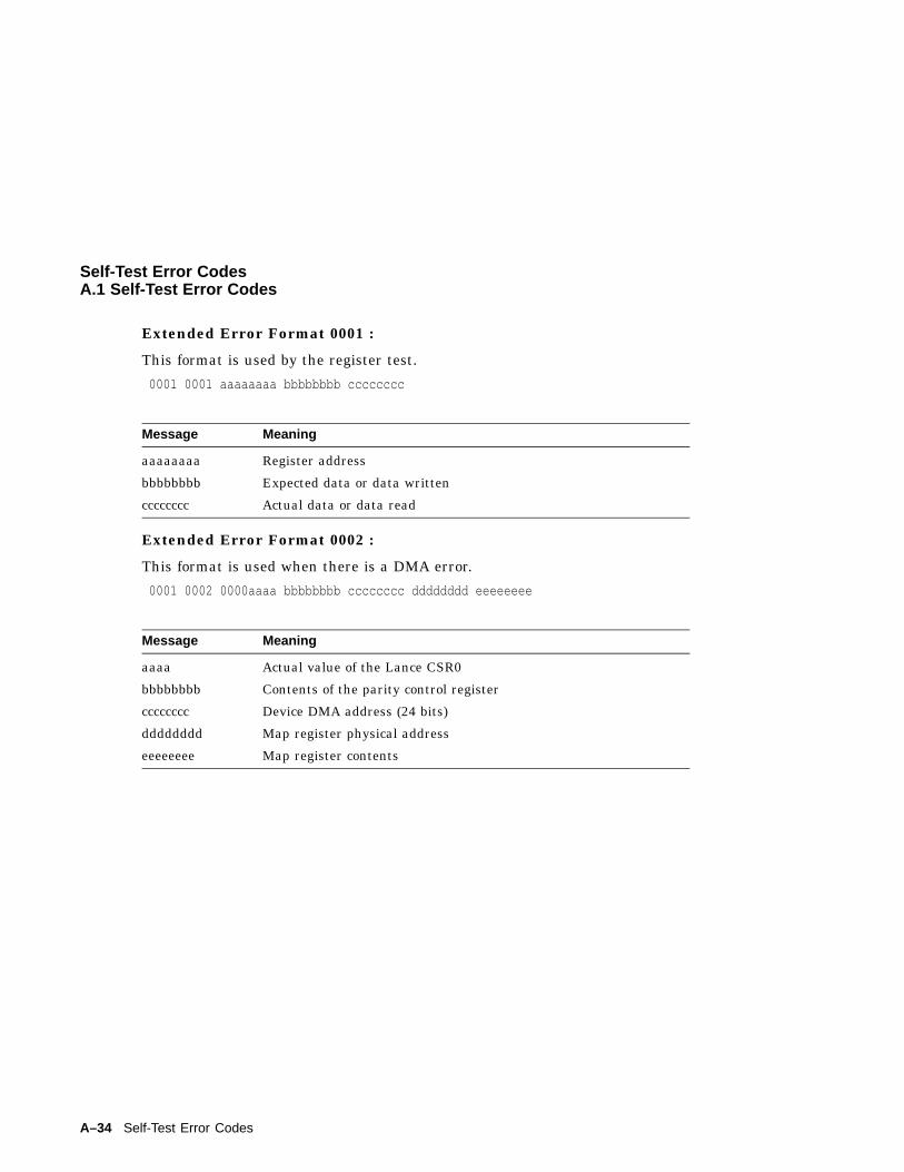
Self-Test Error CodesA.1 Self-Test Error Codes
Extended Error Format 0001 :
This format is used by the register test.
0001 0001 aaaaaaaa bbbbbbbb cccccccc
Message Meaning
aaaaaaaa Register address
bbbbbbbb Expected data or data written
cccccccc Actual data or data read
Extended Error Format 0002 :
This format is used when there is a DMA error.
0001 0002 0000aaaa bbbbbbbb cccccccc dddddddd eeeeeeee
Message Meaning
aaaa Actual value of the Lance CSR0
bbbbbbbb Contents of the parity control register
cccccccc Device DMA address (24 bits)
dddddddd Map register physical address
eeeeeeee Map register contents
A–34 Self-Test Error Codes
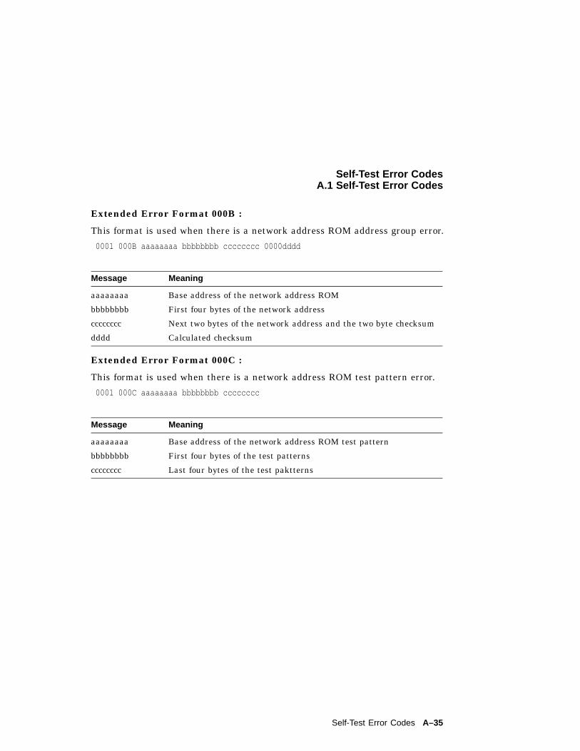
Self-Test Error CodesA.1 Self-Test Error Codes
Extended Error Format 000B :
This format is used when there is a network address ROM address group error.
0001 000B aaaaaaaa bbbbbbbb cccccccc 0000dddd
Message Meaning
aaaaaaaa Base address of the network address ROM
bbbbbbbb First four bytes of the network address
cccccccc Next two bytes of the network address and the two byte checksum
dddd Calculated checksum
Extended Error Format 000C :
This format is used when there is a network address ROM test pattern error.
0001 000C aaaaaaaa bbbbbbbb cccccccc
Message Meaning
aaaaaaaa Base address of the network address ROM test pattern
bbbbbbbb First four bytes of the test patterns
cccccccc Last four bytes of the test paktterns
Self-Test Error Codes A–35
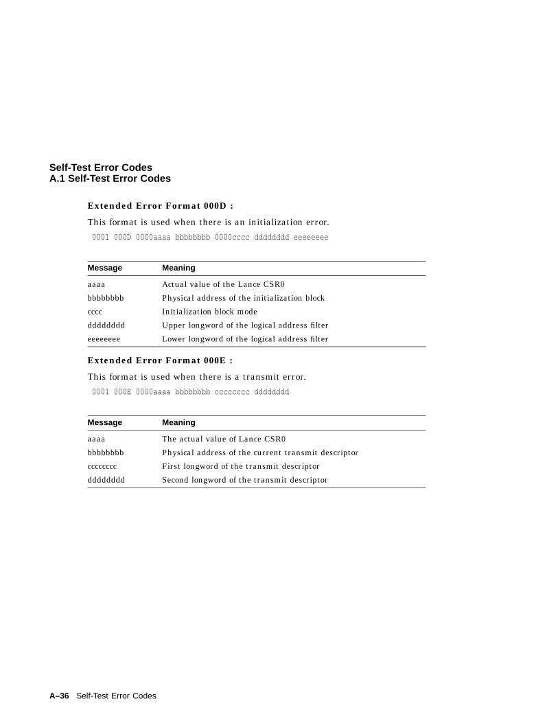
Self-Test Error CodesA.1 Self-Test Error Codes
Extended Error Format 000D :
This format is used when there is an initialization error.
0001 000D 0000aaaa bbbbbbbb 0000cccc dddddddd eeeeeeee
Message Meaning
aaaa Actual value of the Lance CSR0
bbbbbbbb Physical address of the initialization block
cccc Initialization block mode
dddddddd Upper longword of the logical address filter
eeeeeeee Lower longword of the logical address filter
Extended Error Format 000E :
This format is used when there is a transmit error.
0001 000E 0000aaaa bbbbbbbb cccccccc dddddddd
Message Meaning
aaaa The actual value of Lance CSR0
bbbbbbbb Physical address of the current transmit descriptor
cccccccc First longword of the transmit descriptor
dddddddd Second longword of the transmit descriptor
A–36 Self-Test Error Codes
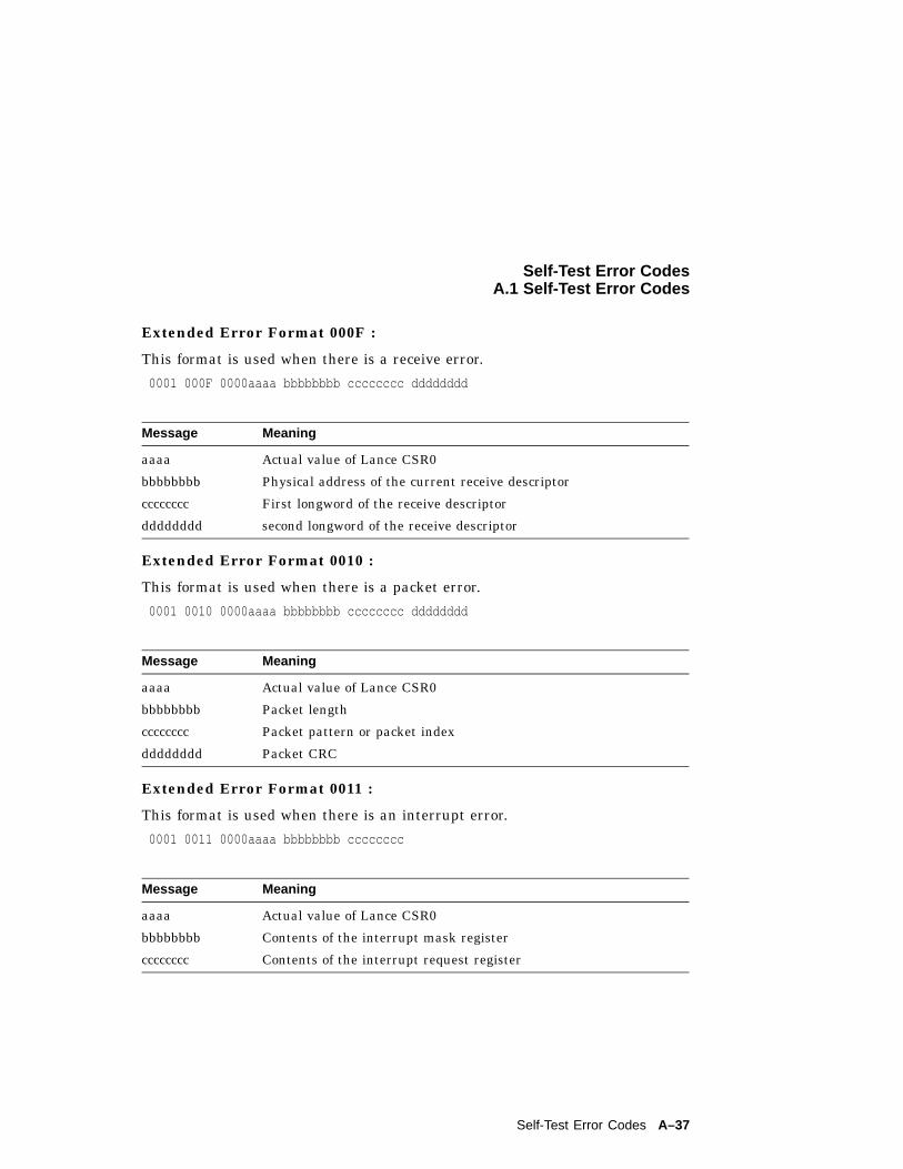
Self-Test Error CodesA.1 Self-Test Error Codes
Extended Error Format 000F :
This format is used when there is a receive error.
0001 000F 0000aaaa bbbbbbbb cccccccc dddddddd
Message Meaning
aaaa Actual value of Lance CSR0
bbbbbbbb Physical address of the current receive descriptor
cccccccc First longword of the receive descriptor
dddddddd second longword of the receive descriptor
Extended Error Format 0010 :
This format is used when there is a packet error.
0001 0010 0000aaaa bbbbbbbb cccccccc dddddddd
Message Meaning
aaaa Actual value of Lance CSR0
bbbbbbbb Packet length
cccccccc Packet pattern or packet index
dddddddd Packet CRC
Extended Error Format 0011 :
This format is used when there is an interrupt error.
0001 0011 0000aaaa bbbbbbbb cccccccc
Message Meaning
aaaa Actual value of Lance CSR0
bbbbbbbb Contents of the interrupt mask register
cccccccc Contents of the interrupt request register
Self-Test Error Codes A–37
BDiagnostic LED Error Codes
B.1 Reading Diagnostic LED CodesThe system uses the eight LEDs on the control panel to indicate the currentexecuting test. At power-up, all the LEDs turn on (LED code is FF(h)), andthen display different codes as the devices are tested.
The LED codes are broken into two fields. The left most four LEDs representthe function pointer to the LED error table that should be referenced wheninterepreting the second (right most) field of LEDs, which represents aparticular test category. LED codes E0h - FFh are reserved for the console.
Each LED error table is preceeded by a section header that includes the LEDcode pointing to that table. Each table header includes the column titled LEDDepiction. In the description, field X indicates that the LED is on, the letter Oindicates the LED is off, and Z is either.
Diagnostic LED Error Codes B–1
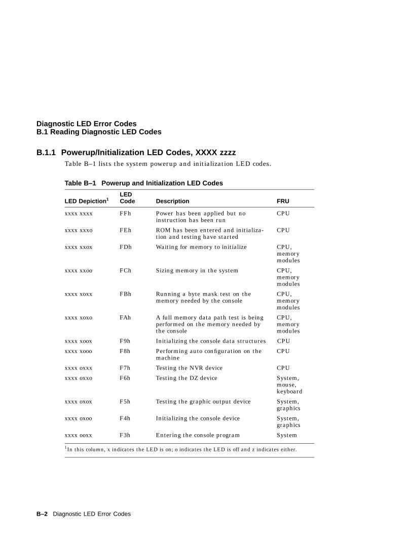
Diagnostic LED Error CodesB.1 Reading Diagnostic LED Codes
B.1.1 Powerup/Initialization LED Codes, XXXX zzzzTable B–1 lists the system powerup and initialization LED codes.
Table B–1 Powerup and Initialization LED Codes
LED Depiction 1LEDCode Description FRU
xxxx xxxx FFh Power has been applied but noinstruction has been run
CPU
xxxx xxxo FEh ROM has been entered and initializa-tion and testing have started
CPU
xxxx xxox FDh Waiting for memory to initialize CPU,memorymodules
xxxx xxoo FCh Sizing memory in the system CPU,memorymodules
xxxx xoxx FBh Running a byte mask test on thememory needed by the console
CPU,memorymodules
xxxx xoxo FAh A full memory data path test is beingperformed on the memory needed bythe console
CPU,memorymodules
xxxx xoox F9h Initializing the console data structures CPU
xxxx xooo F8h Performing auto configuration on themachine
CPU
xxxx oxxx F7h Testing the NVR device CPU
xxxx oxxo F6h Testing the DZ device System,mouse,keyboard
xxxx oxox F5h Testing the graphic output device System,graphics
xxxx oxoo F4h Initializing the console device System,graphics
xxxx ooxx F3h Entering the console program System
1In this column, x indicates the LED is on; o indicates the LED is off and z indicates either.
B–2 Diagnostic LED Error Codes
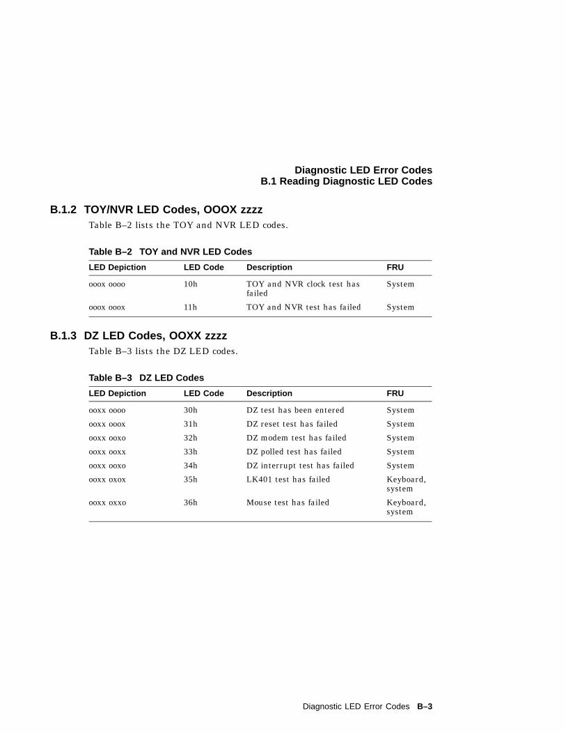
Diagnostic LED Error CodesB.1 Reading Diagnostic LED Codes
B.1.2 TOY/NVR LED Codes, OOOX zzzzTable B–2 lists the TOY and NVR LED codes.
Table B–2 TOY and NVR LED Codes
LED Depiction LED Code Description FRU
ooox oooo 10h TOY and NVR clock test hasfailed
System
ooox ooox 11h TOY and NVR test has failed System
B.1.3 DZ LED Codes, OOXX zzzzTable B–3 lists the DZ LED codes.
Table B–3 DZ LED Codes
LED Depiction LED Code Description FRU
ooxx oooo 30h DZ test has been entered System
ooxx ooox 31h DZ reset test has failed System
ooxx ooxo 32h DZ modem test has failed System
ooxx ooxx 33h DZ polled test has failed System
ooxx ooxo 34h DZ interrupt test has failed System
ooxx oxox 35h LK401 test has failed Keyboard,system
ooxx oxxo 36h Mouse test has failed Keyboard,system
Diagnostic LED Error Codes B–3
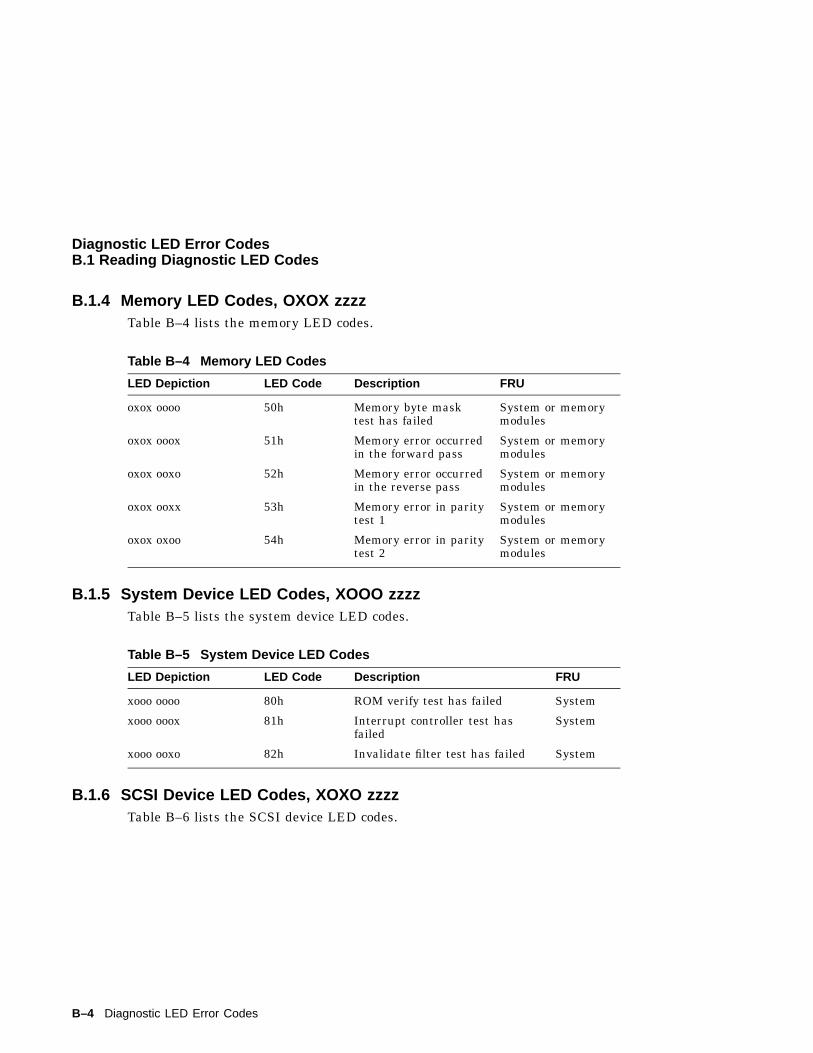
Diagnostic LED Error CodesB.1 Reading Diagnostic LED Codes
B.1.4 Memory LED Codes, OXOX zzzzTable B–4 lists the memory LED codes.
Table B–4 Memory LED Codes
LED Depiction LED Code Description FRU
oxox oooo 50h Memory byte masktest has failed
System or memorymodules
oxox ooox 51h Memory error occurredin the forward pass
System or memorymodules
oxox ooxo 52h Memory error occurredin the reverse pass
System or memorymodules
oxox ooxx 53h Memory error in paritytest 1
System or memorymodules
oxox oxoo 54h Memory error in paritytest 2
System or memorymodules
B.1.5 System Device LED Codes, XOOO zzzzTable B–5 lists the system device LED codes.
Table B–5 System Device LED Codes
LED Depiction LED Code Description FRU
xooo oooo 80h ROM verify test has failed System
xooo ooox 81h Interrupt controller test hasfailed
System
xooo ooxo 82h Invalidate filter test has failed System
B.1.6 SCSI Device LED Codes, XOXO zzzzTable B–6 lists the SCSI device LED codes.
B–4 Diagnostic LED Error Codes
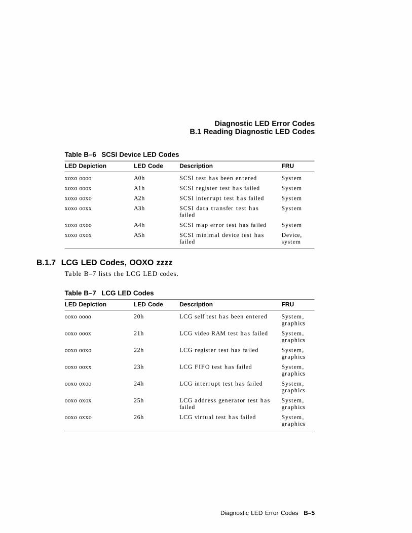
Diagnostic LED Error CodesB.1 Reading Diagnostic LED Codes
Table B–6 SCSI Device LED Codes
LED Depiction LED Code Description FRU
xoxo oooo A0h SCSI test has been entered System
xoxo ooox A1h SCSI register test has failed System
xoxo ooxo A2h SCSI interrupt test has failed System
xoxo ooxx A3h SCSI data transfer test hasfailed
System
xoxo oxoo A4h SCSI map error test has failed System
xoxo oxox A5h SCSI minimal device test hasfailed
Device,system
B.1.7 LCG LED Codes, OOXO zzzzTable B–7 lists the LCG LED codes.
Table B–7 LCG LED Codes
LED Depiction LED Code Description FRU
ooxo oooo 20h LCG self test has been entered System,graphics
ooxo ooox 21h LCG video RAM test has failed System,graphics
ooxo ooxo 22h LCG register test has failed System,graphics
ooxo ooxx 23h LCG FIFO test has failed System,graphics
ooxo oxoo 24h LCG interrupt test has failed System,graphics
ooxo oxox 25h LCG address generator test hasfailed
System,graphics
ooxo oxxo 26h LCG virtual test has failed System,graphics
Diagnostic LED Error Codes B–5
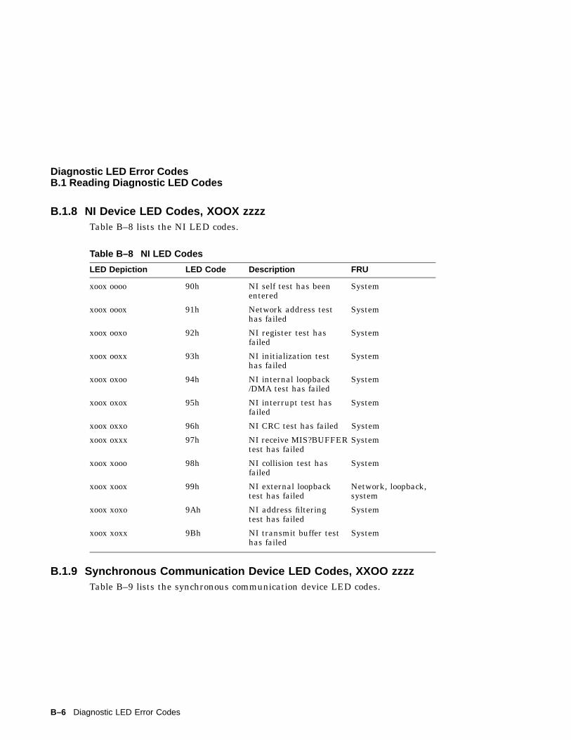
Diagnostic LED Error CodesB.1 Reading Diagnostic LED Codes
B.1.8 NI Device LED Codes, XOOX zzzzTable B–8 lists the NI LED codes.
Table B–8 NI LED Codes
LED Depiction LED Code Description FRU
xoox oooo 90h NI self test has beenentered
System
xoox ooox 91h Network address testhas failed
System
xoox ooxo 92h NI register test hasfailed
System
xoox ooxx 93h NI initialization testhas failed
System
xoox oxoo 94h NI internal loopback/DMA test has failed
System
xoox oxox 95h NI interrupt test hasfailed
System
xoox oxxo 96h NI CRC test has failed System
xoox oxxx 97h NI receive MIS?BUFFERtest has failed
System
xoox xooo 98h NI collision test hasfailed
System
xoox xoox 99h NI external loopbacktest has failed
Network, loopback,system
xoox xoxo 9Ah NI address filteringtest has failed
System
xoox xoxx 9Bh NI transmit buffer testhas failed
System
B.1.9 Synchronous Communication Device LED Codes, XXOO zzzzTable B–9 lists the synchronous communication device LED codes.
B–6 Diagnostic LED Error Codes
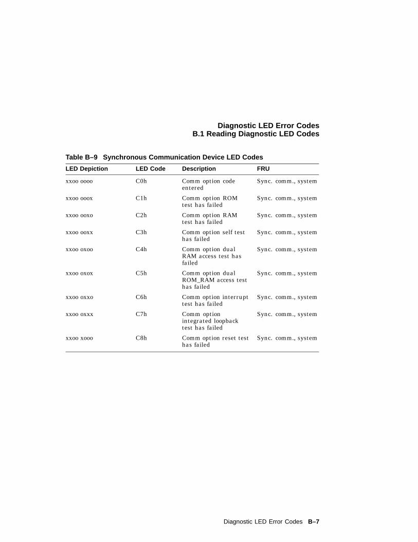
Diagnostic LED Error CodesB.1 Reading Diagnostic LED Codes
Table B–9 Synchronous Communication Device LED Codes
LED Depiction LED Code Description FRU
xxoo oooo C0h Comm option codeentered
Sync. comm., system
xxoo ooox C1h Comm option ROMtest has failed
Sync. comm., system
xxoo ooxo C2h Comm option RAMtest has failed
Sync. comm., system
xxoo ooxx C3h Comm option self testhas failed
Sync. comm., system
xxoo oxoo C4h Comm option dualRAM access test hasfailed
Sync. comm., system
xxoo oxox C5h Comm option dualROM_RAM access testhas failed
Sync. comm., system
xxoo oxxo C6h Comm option interrupttest has failed
Sync. comm., system
xxoo oxxx C7h Comm optionintegrated loopbacktest has failed
Sync. comm., system
xxoo xooo C8h Comm option reset testhas failed
Sync. comm., system
Diagnostic LED Error Codes B–7
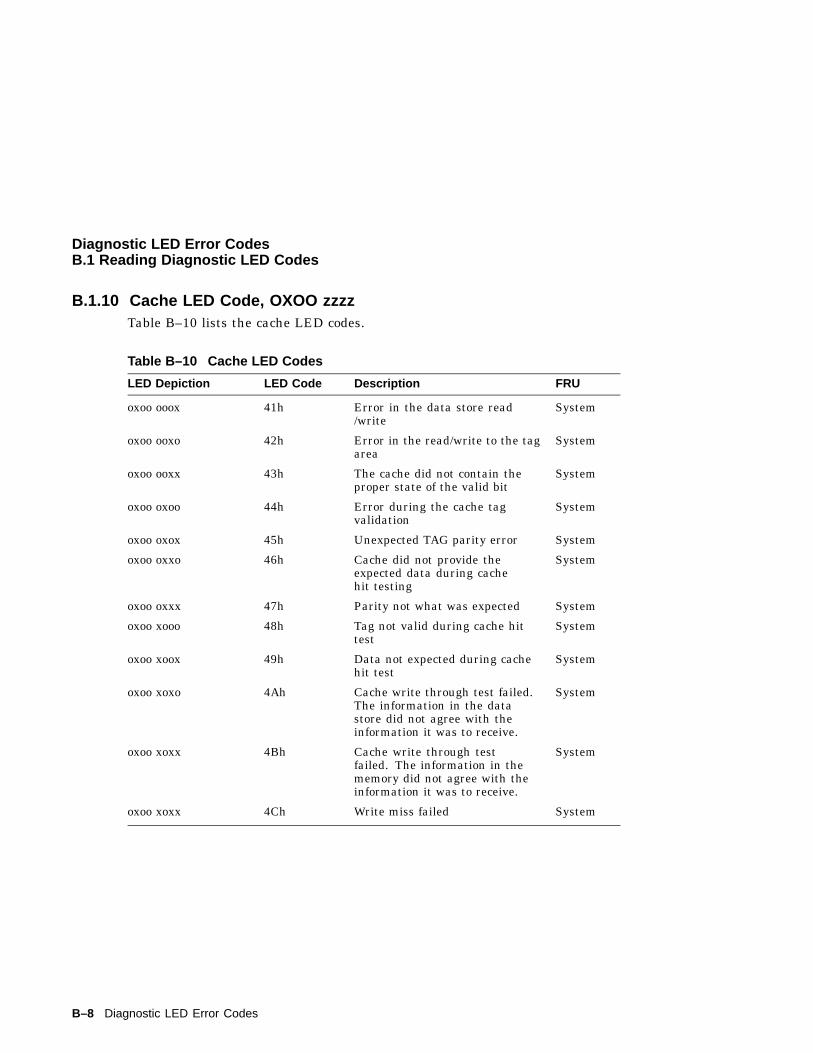
Diagnostic LED Error CodesB.1 Reading Diagnostic LED Codes
B.1.10 Cache LED Code, OXOO zzzzTable B–10 lists the cache LED codes.
Table B–10 Cache LED Codes
LED Depiction LED Code Description FRU
oxoo ooox 41h Error in the data store read/write
System
oxoo ooxo 42h Error in the read/write to the tagarea
System
oxoo ooxx 43h The cache did not contain theproper state of the valid bit
System
oxoo oxoo 44h Error during the cache tagvalidation
System
oxoo oxox 45h Unexpected TAG parity error System
oxoo oxxo 46h Cache did not provide theexpected data during cachehit testing
System
oxoo oxxx 47h Parity not what was expected System
oxoo xooo 48h Tag not valid during cache hittest
System
oxoo xoox 49h Data not expected during cachehit test
System
oxoo xoxo 4Ah Cache write through test failed.The information in the datastore did not agree with theinformation it was to receive.
System
oxoo xoxx 4Bh Cache write through testfailed. The information in thememory did not agree with theinformation it was to receive.
System
oxoo xoxx 4Ch Write miss failed System
B–8 Diagnostic LED Error Codes
CTroubleshooting
The troubleshooting techniques described in Appendix C do not identify allpossible problems that may occur nor do the actions suggested remedy allproblems. If the powerup tests complete, the error message displayed on theconsole can be used to identify a failed FRU, or you can run the self test,system test, or utility tests in Customer Service mode to help isolate failingFRUs. Information on interpreting self test error messages is in Appendix A.
Use the diagnostic LEDs on the front of the system to help diagnose problemswhere the system is unable to setup the console. Information on interpretingdiagnostic LED codes is in Appendix B.
Troubleshooting C–1
TroubleshootingC.1 Troubleshooting Symptoms and Corrective Actions
C.1 Troubleshooting Symptoms and Corrective ActionsThis section provides problem isolation and repair recommendations. TheVAXstation 4000 VLC system is broken down into the following operatingareas and troubleshooting tables for each area are provided.
• System problems
• Monitor problems
• Mouse/Tablet problems
• Keyboard problems
• Drive problems
• Network problems
• Audio Problems
• Expansion box problems
C–2 Troubleshooting
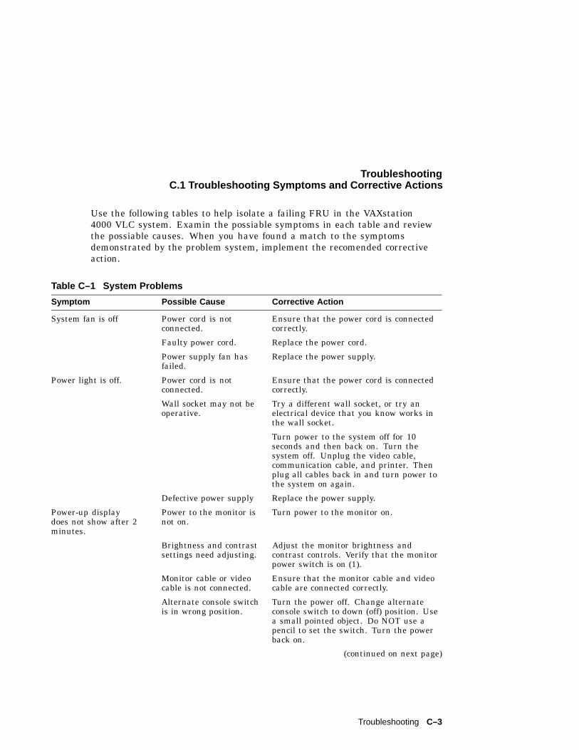
TroubleshootingC.1 Troubleshooting Symptoms and Corrective Actions
Use the following tables to help isolate a failing FRU in the VAXstation4000 VLC system. Examin the possiable symptoms in each table and reviewthe possiable causes. When you have found a match to the symptomsdemonstrated by the problem system, implement the recomended correctiveaction.
Table C–1 System Problems
Symptom Possible Cause Corrective Action
System fan is off Power cord is notconnected.
Ensure that the power cord is connectedcorrectly.
Faulty power cord. Replace the power cord.
Power supply fan hasfailed.
Replace the power supply.
Power light is off. Power cord is notconnected.
Ensure that the power cord is connectedcorrectly.
Wall socket may not beoperative.
Try a different wall socket, or try anelectrical device that you know works inthe wall socket.
Turn power to the system off for 10seconds and then back on. Turn thesystem off. Unplug the video cable,communication cable, and printer. Thenplug all cables back in and turn power tothe system on again.
Defective power supply Replace the power supply.
Power-up displaydoes not show after 2minutes.
Power to the monitor isnot on.
Turn power to the monitor on.
Brightness and contrastsettings need adjusting.
Adjust the monitor brightness andcontrast controls. Verify that the monitorpower switch is on (1).
Monitor cable or videocable is not connected.
Ensure that the monitor cable and videocable are connected correctly.
Alternate console switchis in wrong position.
Turn the power off. Change alternateconsole switch to down (off) position. Usea small pointed object. Do NOT use apencil to set the switch. Turn the powerback on.
(continued on next page)
Troubleshooting C–3
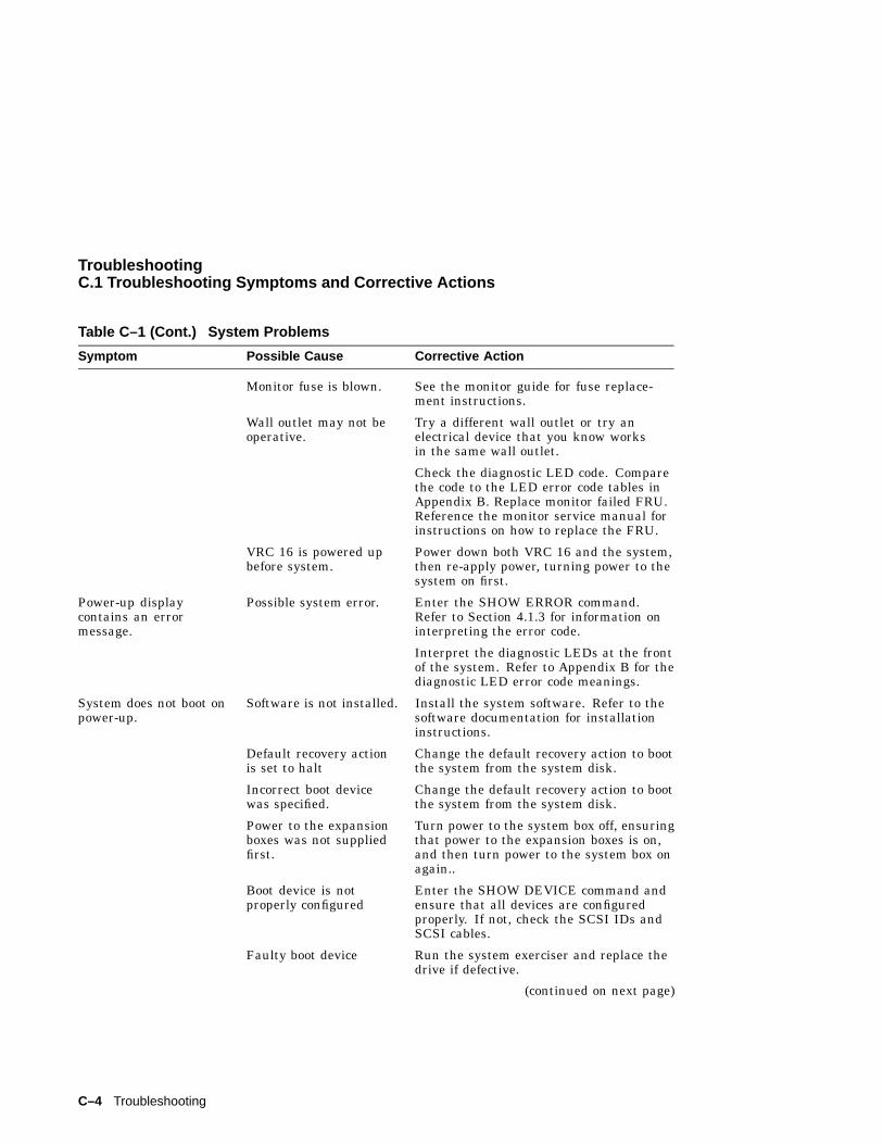
TroubleshootingC.1 Troubleshooting Symptoms and Corrective Actions
Table C–1 (Cont.) System Problems
Symptom Possible Cause Corrective Action
Monitor fuse is blown. See the monitor guide for fuse replace-ment instructions.
Wall outlet may not beoperative.
Try a different wall outlet or try anelectrical device that you know worksin the same wall outlet.
Check the diagnostic LED code. Comparethe code to the LED error code tables inAppendix B. Replace monitor failed FRU.Reference the monitor service manual forinstructions on how to replace the FRU.
VRC 16 is powered upbefore system.
Power down both VRC 16 and the system,then re-apply power, turning power to thesystem on first.
Power-up displaycontains an errormessage.
Possible system error. Enter the SHOW ERROR command.Refer to Section 4.1.3 for information oninterpreting the error code.
Interpret the diagnostic LEDs at the frontof the system. Refer to Appendix B for thediagnostic LED error code meanings.
System does not boot onpower-up.
Software is not installed. Install the system software. Refer to thesoftware documentation for installationinstructions.
Default recovery actionis set to halt
Change the default recovery action to bootthe system from the system disk.
Incorrect boot devicewas specified.
Change the default recovery action to bootthe system from the system disk.
Power to the expansionboxes was not suppliedfirst.
Turn power to the system box off, ensuringthat power to the expansion boxes is on,and then turn power to the system box onagain..
Boot device is notproperly configured
Enter the SHOW DEVICE command andensure that all devices are configuredproperly. If not, check the SCSI IDs andSCSI cables.
Faulty boot device Run the system exerciser and replace thedrive if defective.
(continued on next page)
C–4 Troubleshooting
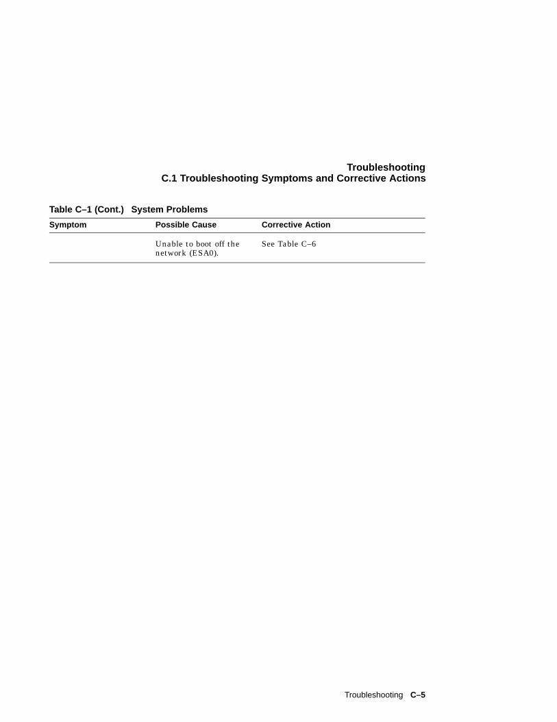
TroubleshootingC.1 Troubleshooting Symptoms and Corrective Actions
Table C–1 (Cont.) System Problems
Symptom Possible Cause Corrective Action
Unable to boot off thenetwork (ESA0).
See Table C–6
Troubleshooting C–5
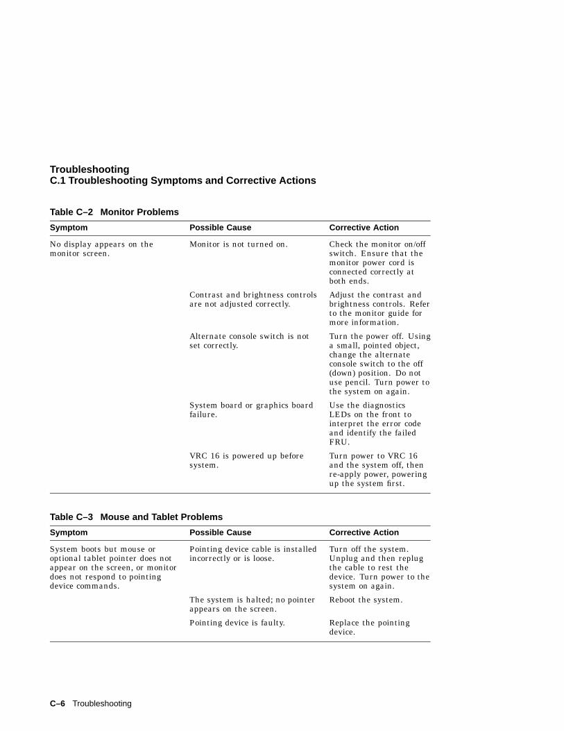
TroubleshootingC.1 Troubleshooting Symptoms and Corrective Actions
Table C–2 Monitor Problems
Symptom Possible Cause Corrective Action
No display appears on themonitor screen.
Monitor is not turned on. Check the monitor on/offswitch. Ensure that themonitor power cord isconnected correctly atboth ends.
Contrast and brightness controlsare not adjusted correctly.
Adjust the contrast andbrightness controls. Referto the monitor guide formore information.
Alternate console switch is notset correctly.
Turn the power off. Usinga small, pointed object,change the alternateconsole switch to the off(down) position. Do notuse pencil. Turn power tothe system on again.
System board or graphics boardfailure.
Use the diagnosticsLEDs on the front tointerpret the error codeand identify the failedFRU.
VRC 16 is powered up beforesystem.
Turn power to VRC 16and the system off, thenre-apply power, poweringup the system first.
Table C–3 Mouse and Tablet Problems
Symptom Possible Cause Corrective Action
System boots but mouse oroptional tablet pointer does notappear on the screen, or monitordoes not respond to pointingdevice commands.
Pointing device cable is installedincorrectly or is loose.
Turn off the system.Unplug and then replugthe cable to rest thedevice. Turn power to thesystem on again.
The system is halted; no pointerappears on the screen.
Reboot the system.
Pointing device is faulty. Replace the pointingdevice.
C–6 Troubleshooting
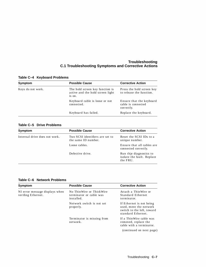
TroubleshootingC.1 Troubleshooting Symptoms and Corrective Actions
Table C–4 Keyboard Problems
Symptom Possible Cause Corrective Action
Keys do not work. The hold screen key function isactive and the hold screen lightis on.
Press the hold screen keyto release the function.
Keyboard cable is loose or notconnected.
Ensure that the keyboardcable is connectedcorrectly.
Keyboard has failed. Replace the keyboard.
Table C–5 Drive Problems
Symptom Possible Cause Corrective Action
Internal drive does not work. Two SCSI identifiers are set tothe same ID number.
Reset the SCSI IDs to aunique number.
Loose cables. Ensure that all cables areconnected correctly.
Defective drive. Run thje diagnostics toisolate the fault. Replacethe FRU.
Table C–6 Network Problems
Symptom Possible Cause Corrective Action
NI error message displays whenverifing Ethernet.
No ThinWire or ThickWireterminator or cable wasinstalled.
Attach a ThinWire orStandard Ethernetterminator.
Network switch is not setproperly.
If Ethernet is not beingused, move the networkswitch to the left, towardstandard Ethernet.
Terminator is missing fromnetwork.
If a ThinWire cable wasremoved, replace thecable with a terminator.
(continued on next page)
Troubleshooting C–7
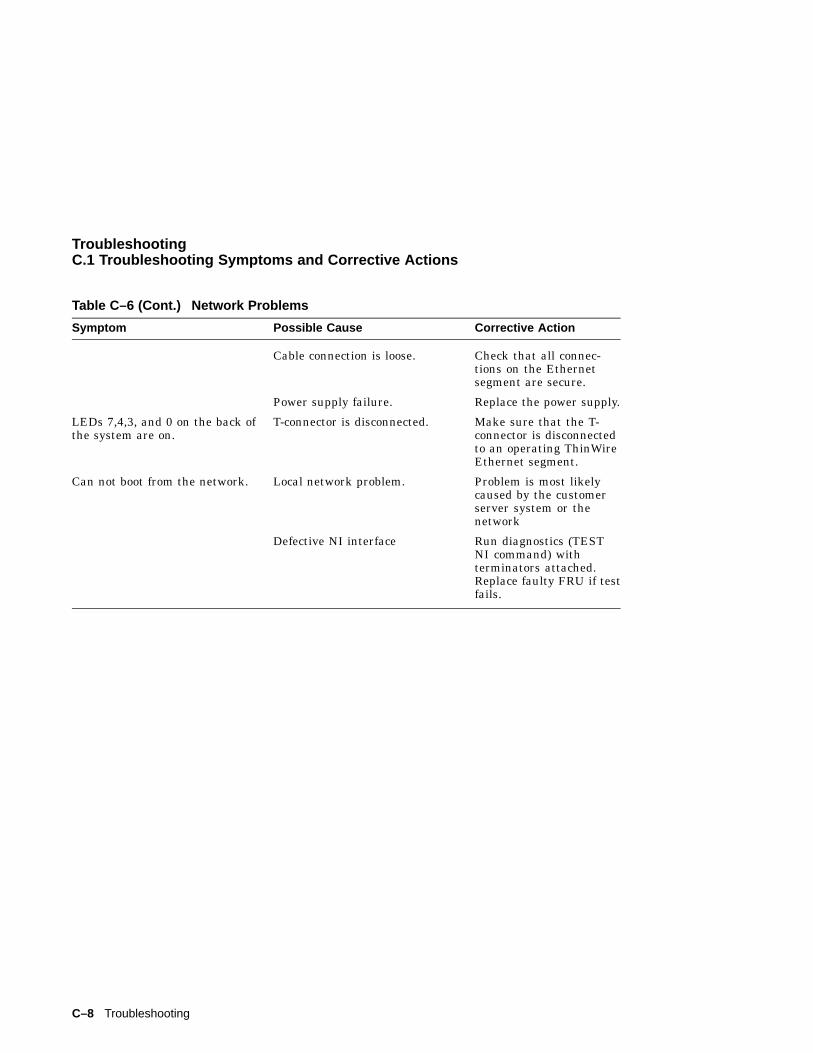
TroubleshootingC.1 Troubleshooting Symptoms and Corrective Actions
Table C–6 (Cont.) Network Problems
Symptom Possible Cause Corrective Action
Cable connection is loose. Check that all connec-tions on the Ethernetsegment are secure.
Power supply failure. Replace the power supply.
LEDs 7,4,3, and 0 on the back ofthe system are on.
T-connector is disconnected. Make sure that the T-connector is disconnectedto an operating ThinWireEthernet segment.
Can not boot from the network. Local network problem. Problem is most likelycaused by the customerserver system or thenetwork
Defective NI interface Run diagnostics (TESTNI command) withterminators attached.Replace faulty FRU if testfails.
C–8 Troubleshooting
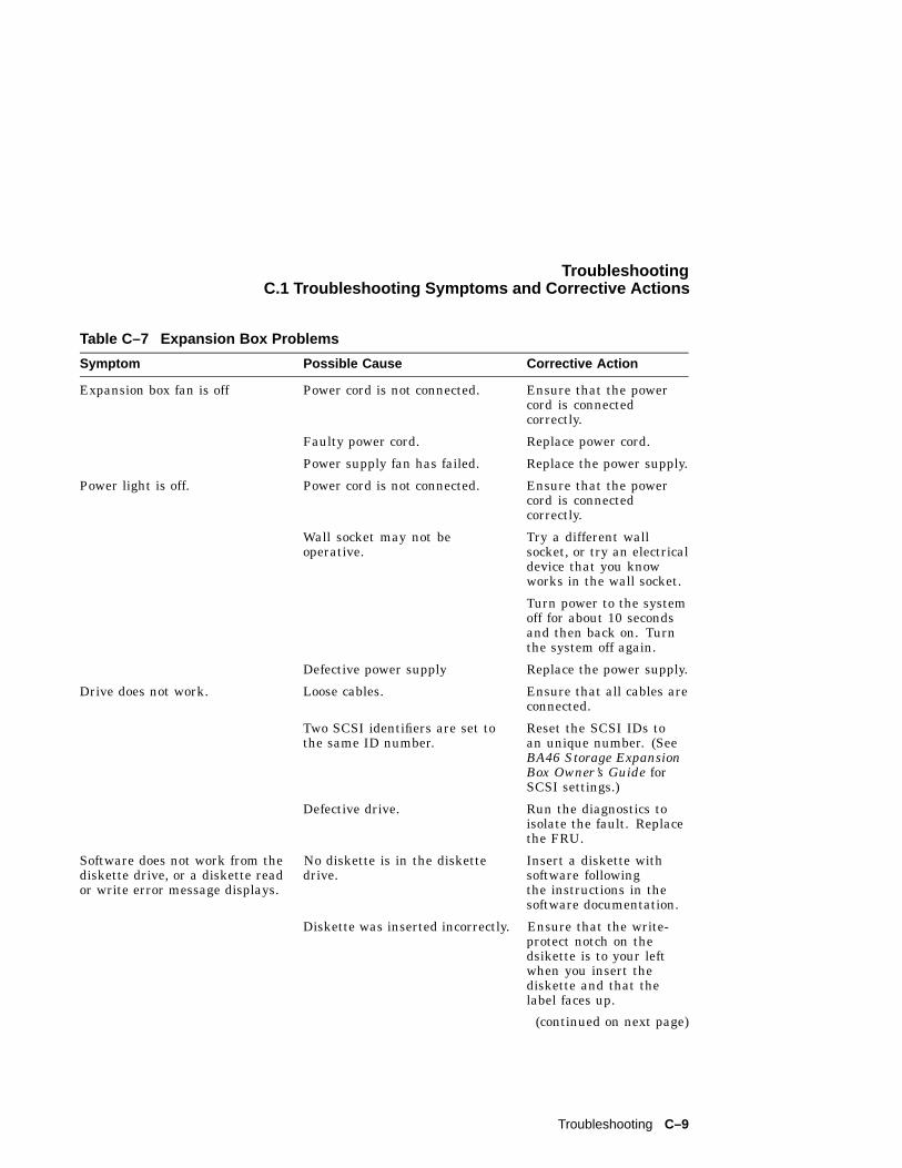
TroubleshootingC.1 Troubleshooting Symptoms and Corrective Actions
Table C–7 Expansion Box Problems
Symptom Possible Cause Corrective Action
Expansion box fan is off Power cord is not connected. Ensure that the powercord is connectedcorrectly.
Faulty power cord. Replace power cord.
Power supply fan has failed. Replace the power supply.
Power light is off. Power cord is not connected. Ensure that the powercord is connectedcorrectly.
Wall socket may not beoperative.
Try a different wallsocket, or try an electricaldevice that you knowworks in the wall socket.
Turn power to the systemoff for about 10 secondsand then back on. Turnthe system off again.
Defective power supply Replace the power supply.
Drive does not work. Loose cables. Ensure that all cables areconnected.
Two SCSI identifiers are set tothe same ID number.
Reset the SCSI IDs toan unique number. (SeeBA46 Storage ExpansionBox Owner’s Guide forSCSI settings.)
Defective drive. Run the diagnostics toisolate the fault. Replacethe FRU.
Software does not work from thediskette drive, or a diskette reador write error message displays.
No diskette is in the diskettedrive.
Insert a diskette withsoftware followingthe instructions in thesoftware documentation.
Diskette was inserted incorrectly. Ensure that the write-protect notch on thedsikette is to your leftwhen you insert thediskette and that thelabel faces up.
(continued on next page)
Troubleshooting C–9
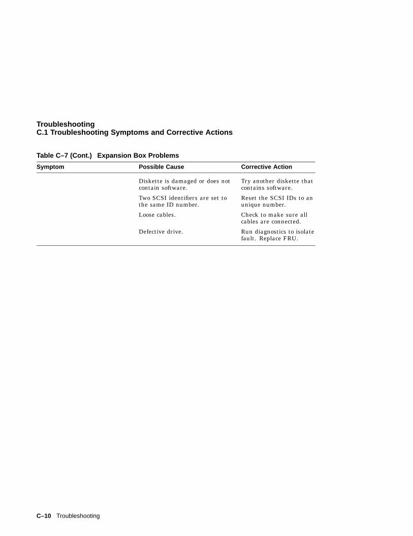
TroubleshootingC.1 Troubleshooting Symptoms and Corrective Actions
Table C–7 (Cont.) Expansion Box Problems
Symptom Possible Cause Corrective Action
Diskette is damaged or does notcontain software.
Try another diskette thatcontains software.
Two SCSI identifiers are set tothe same ID number.
Reset the SCSI IDs to anunique number.
Loose cables. Check to make sure allcables are connected.
Defective drive. Run diagnostics to isolatefault. Replace FRU.
C–10 Troubleshooting
DVAXstation 4000 VLC Part Numbers
D.1 Part NumbersTable D–1 contains the part numbers for the VAXstation 4000 VLC workstationfield replaceable units. These FRUs can be ordered through Digital Services.
VAXstation 4000 VLC Part Numbers D–1
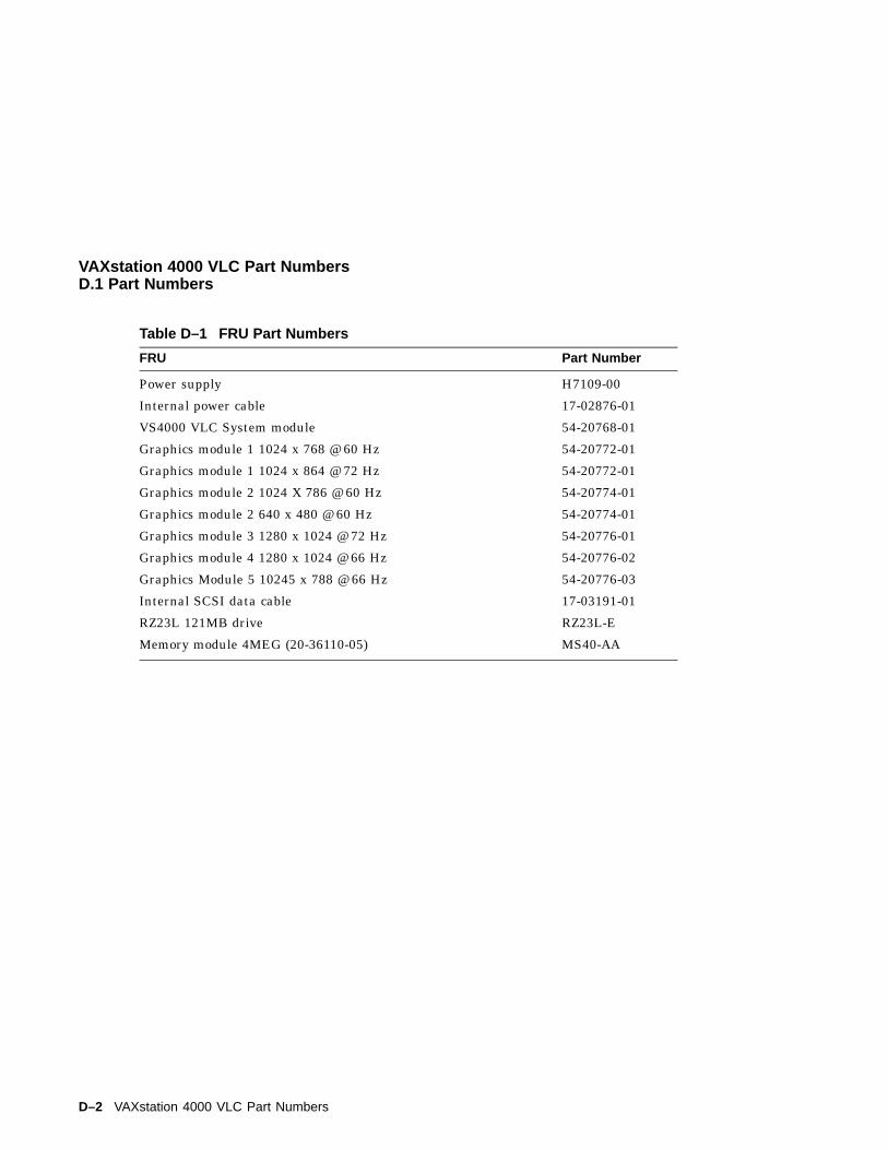
VAXstation 4000 VLC Part NumbersD.1 Part Numbers
Table D–1 FRU Part Numbers
FRU Part Number
Power supply H7109-00
Internal power cable 17-02876-01
VS4000 VLC System module 54-20768-01
Graphics module 1 1024 x 768 @ 60 Hz 54-20772-01
Graphics module 1 1024 x 864 @ 72 Hz 54-20772-01
Graphics module 2 1024 X 786 @ 60 Hz 54-20774-01
Graphics module 2 640 x 480 @ 60 Hz 54-20774-01
Graphics module 3 1280 x 1024 @ 72 Hz 54-20776-01
Graphics module 4 1280 x 1024 @ 66 Hz 54-20776-02
Graphics Module 5 10245 x 788 @ 66 Hz 54-20776-03
Internal SCSI data cable 17-03191-01
RZ23L 121MB drive RZ23L-E
Memory module 4MEG (20-36110-05) MS40-AA
D–2 VAXstation 4000 VLC Part Numbers
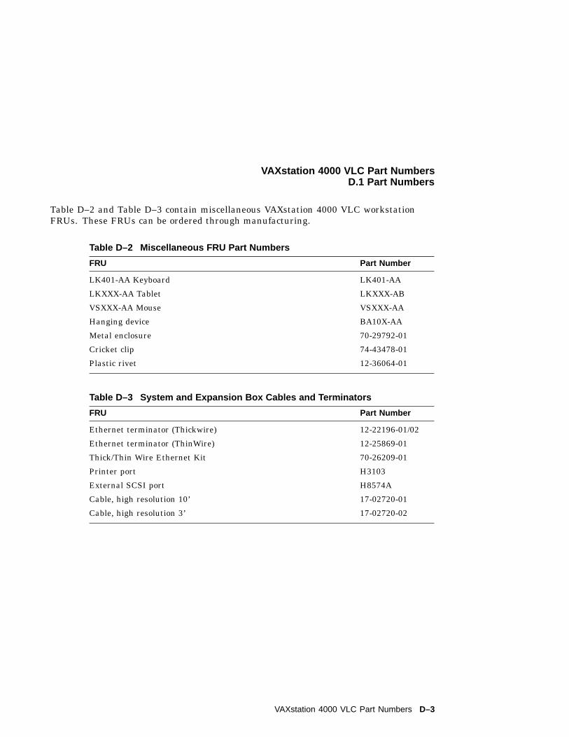
VAXstation 4000 VLC Part NumbersD.1 Part Numbers
Table D–2 and Table D–3 contain miscellaneous VAXstation 4000 VLC workstationFRUs. These FRUs can be ordered through manufacturing.
Table D–2 Miscellaneous FRU Part Numbers
FRU Part Number
LK401-AA Keyboard LK401-AA
LKXXX-AA Tablet LKXXX-AB
VSXXX-AA Mouse VSXXX-AA
Hanging device BA10X-AA
Metal enclosure 70-29792-01
Cricket clip 74-43478-01
Plastic rivet 12-36064-01
Table D–3 System and Expansion Box Cables and Terminators
FRU Part Number
Ethernet terminator (Thickwire) 12-22196-01/02
Ethernet terminator (ThinWire) 12-25869-01
Thick/Thin Wire Ethernet Kit 70-26209-01
Printer port H3103
External SCSI port H8574A
Cable, high resolution 10’ 17-02720-01
Cable, high resolution 3’ 17-02720-02
VAXstation 4000 VLC Part Numbers D–3
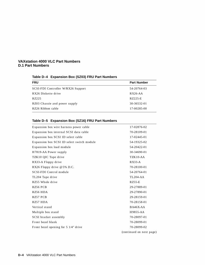
VAXstation 4000 VLC Part NumbersD.1 Part Numbers
Table D–4 Expansion Box (SZ03) FRU Part Numbers
FRU Part Number
SCSI-FDI Controller W/RX26 Support 54-20764-03
RX26 Diskette drive RX26-AA
RZ225 RZ225-E
RZ03 Chassie and power supply 30-36532-01
RZ26 Ribbon cable 17-00285-00
Table D–5 Expansion Box (SZ16) FRU Part Numbers
Expansion box wire harness power cable 17-02876-02
Expansion box internal SCSI data cable 70-28109-01
Expansion box SCSI ID select cable 17-02445-01
Expansion box SCSI ID select switch module 54-19325-02
Expansion box load module 54-20422-01
H7819-AA Power supply 30-34690-01
TZK10 QIC Tape drive TZK10-AA
RX33-A Floppy drive RX33-A
RX26 Floppy drive @ 5% D.C. 70-28100-01
SCSI-FDI Control module 54-20764-01
TL204 Tape drive TL204-AA
RZ55 Whole drive RZ55-E
RZ56 PCB 29-27889-01
RZ56 HDA 29-27890-01
RZ57 PCB 29-28159-01
RZ57 HDA 70-28158-01
Vertical stand BA46X-AA
Multiple box stand H9855-AA
SCSI bracket assembly 70-28097-01
Front bezel blank 70-28099-01
Front bezel opening for 5 1/4" drive 70-28099-02
(continued on next page)
D–4 VAXstation 4000 VLC Part Numbers
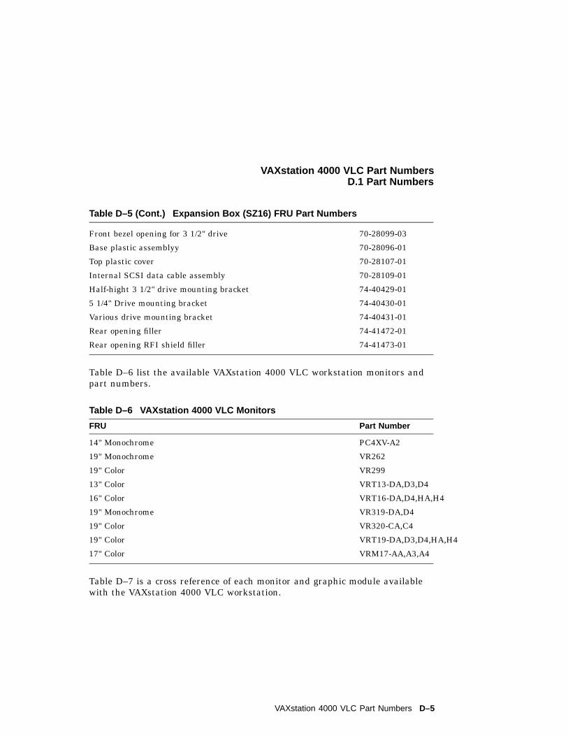
VAXstation 4000 VLC Part NumbersD.1 Part Numbers
Table D–5 (Cont.) Expansion Box (SZ16) FRU Part Numbers
Front bezel opening for 3 1/2" drive 70-28099-03
Base plastic assemblyy 70-28096-01
Top plastic cover 70-28107-01
Internal SCSI data cable assembly 70-28109-01
Half-hight 3 1/2" drive mounting bracket 74-40429-01
5 1/4" Drive mounting bracket 74-40430-01
Various drive mounting bracket 74-40431-01
Rear opening filler 74-41472-01
Rear opening RFI shield filler 74-41473-01
Table D–6 list the available VAXstation 4000 VLC workstation monitors andpart numbers.
Table D–6 VAXstation 4000 VLC Monitors
FRU Part Number
14" Monochrome PC4XV-A2
19" Monochrome VR262
19" Color VR299
13" Color VRT13-DA,D3,D4
16" Color VRT16-DA,D4,HA,H4
19" Monochrome VR319-DA,D4
19" Color VR320-CA,C4
19" Color VRT19-DA,D3,D4,HA,H4
17" Color VRM17-AA,A3,A4
Table D–7 is a cross reference of each monitor and graphic module availablewith the VAXstation 4000 VLC workstation.
VAXstation 4000 VLC Part Numbers D–5
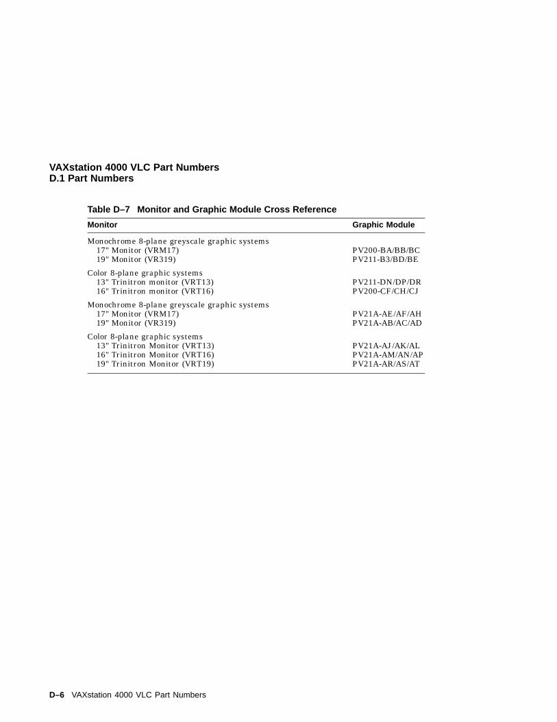
VAXstation 4000 VLC Part NumbersD.1 Part Numbers
Table D–7 Monitor and Graphic Module Cross Reference
Monitor Graphic Module
Monochrome 8-plane greyscale graphic systems17" Monitor (VRM17)19" Monitor (VR319)
PV200-BA/BB/BCPV211-B3/BD/BE
Color 8-plane graphic systems13" Trinitron monitor (VRT13)16" Trinitron monitor (VRT16)
PV211-DN/DP/DRPV200-CF/CH/CJ
Monochrome 8-plane greyscale graphic systems17" Monitor (VRM17)19" Monitor (VR319)
PV21A-AE/AF/AHPV21A-AB/AC/AD
Color 8-plane graphic systems13" Trinitron Monitor (VRT13)16" Trinitron Monitor (VRT16)19" Trinitron Monitor (VRT19)
PV21A-AJ/AK/ALPV21A-AM/AN/APPV21A-AR/AS/AT
D–6 VAXstation 4000 VLC Part Numbers
Index
AAudio Self Test, 4–14AUD Self Test
see audio self test, 4–14AVS
see voltage select, 2–4
BBattery Backup, 1–18Broadcast Address, 1–21
CCache Self Test, 4–11Configuration Table, 3–9
device, 3–11main, 3–10
Console Driver Interface, 3–19Console Mode, 3–3Console Overview, 3–3Console Port Driver, 3–22CPU, 1–6Cricket Clip, 2–3
DDiagnostic LED Codes, B–1
cache, B–8DZ, B–3LCG, B–5memory, B–4NI, B–6SCSI device, B–4
Diagnostic LED Codes (cont’d)sysnc comm device, B–6system device, B–4TOY and NVR, B–3
Diagnostic LEDs Codespowerup/initialization, B–2
Diagnostic Test, 4–1DMA Mapping, 1–13Driver Descriptor, 3–15Drive Removal, 5–7DZ Self Test, 4–10
EError Codes, A–1
audio, A–17audio extended codes, A–17cache, A–22cache extended codes, A–22DZ, A–2DZ suberror, A–3floating point unit (FPU), A–19FPU extended code, A–21interval timer, A–7LCG, A–23LCG extended codes, A–26memory, A–5memory extended code, A–5memory management unit (MMU), A–6NI, A–29NI extended code, A–33SCSI, A–8SCSI extended code, A–9SYS self-test extended code, A–7system device, A–7
Index–1
Error Codes (cont’d)TOY/NVR, A–1
Extended Self Test, 3–4, 4–1
FField Replaceable Units, 5–1firmware, 3–1Floating Point Unit Self Test, 4–11FPU Self Test
see floating point unit self test, 4–11FRUs
see field replaceable units, 5–1
GGraphics Controller, 1–15
HHalt, 3–3Hard Disk Drive Replacement, 5–9
II/O Panel, 2–7, 2–8Interfacing Diagnostic Drivers, 3–17Internal Cabling, 2–7Interrupt Sources, 1–10Interrupt Vector, 1–10Interval Timer Self Test, 4–12IT Self Test
see interval timer self test, 4–12
LLCG Removal, 5–13LCG Self Test, 4–9
MMain Memory, 1–11Main Memory Requests, 1–12Mass Storage, 2–3Memorr Module Identification, 5–16
Memory Self Test, 4–12Module Removal
MS44 memory module, 5–14Multicast Address, 1–21Multicast-group Address, 1–21
NNetwork Addresses, 1–21Network Controller, 1–20Network Interconnect Self Test, 4–13NI Self Test
see network interconnect self test, 4–13NVR Self Test, 4–8
PPacket Format, 1–20Physical Address, 1–21Power Supply, 2–3, 5–11
removal, 5–11Power Supply Specifications, 2–4Power-Up Initialization Code
power-up sequence, 3–2Power-Up Initialization Code Overview, 3–2Power-UP Self Test, 4–1
RRemoving and Replacing, 5–1
SScreen Formats
graphics controller, 1–16SCSI Bus Signals, 1–22SCSI Self Test, 4–14Serial Line Controller, 1–17Shared Console Interface Area, 3–20SYS Self Test
see system self test, 4–11System Box, 2–1, 2–2System Box right side, 2–6System Console Commands
Memory, 4–28DEPOSIT, 4–28
Index–2
System Console CommandsMemory (cont’d)
EXAMINE, 4–29FIND, 4–30MOVE, 4–31
Miscellaneous Commands, 4–33HELP or ?, 4–34LOGIN, 4–34REPEAT, 4–34
Processor Control, 4–31BOOT, 4–31CONTINUE, 4–32START, 4–33
SET/SHOW, 4–17, 4–19, 4–23BFLG, 4–19BOOT, 4–19CONFIG, 4–20DEVICE, 4–20DIAGENV, 4–21ERROR, 4–23ETHER, 4–23FBOOT, 4–24HALT, 4–24KBD, 4–25MEM, 4–25MOP, 4–26PSE and PWSD, 4–26SCSI, 4–27
TRIGGER, 4–27VER, 4–27
System Controls, 2–6System Cover
removal, 5–6System Devices, 2–7System Module Removal, 5–13System ROM
overview, 3–6part Format, 3–6set format, 3–7
System Self Test, 4–11
TTime-of-Year Clock, 1–18TOY Self Test, 4–8Troubleshooting
table, C–2
UUtilities Test, 4–1Utility Test, 3–5
VVoltage Select, 2–4
Index–3