Embed Size (px)
Citation preview
1
VariSpringVariSpring
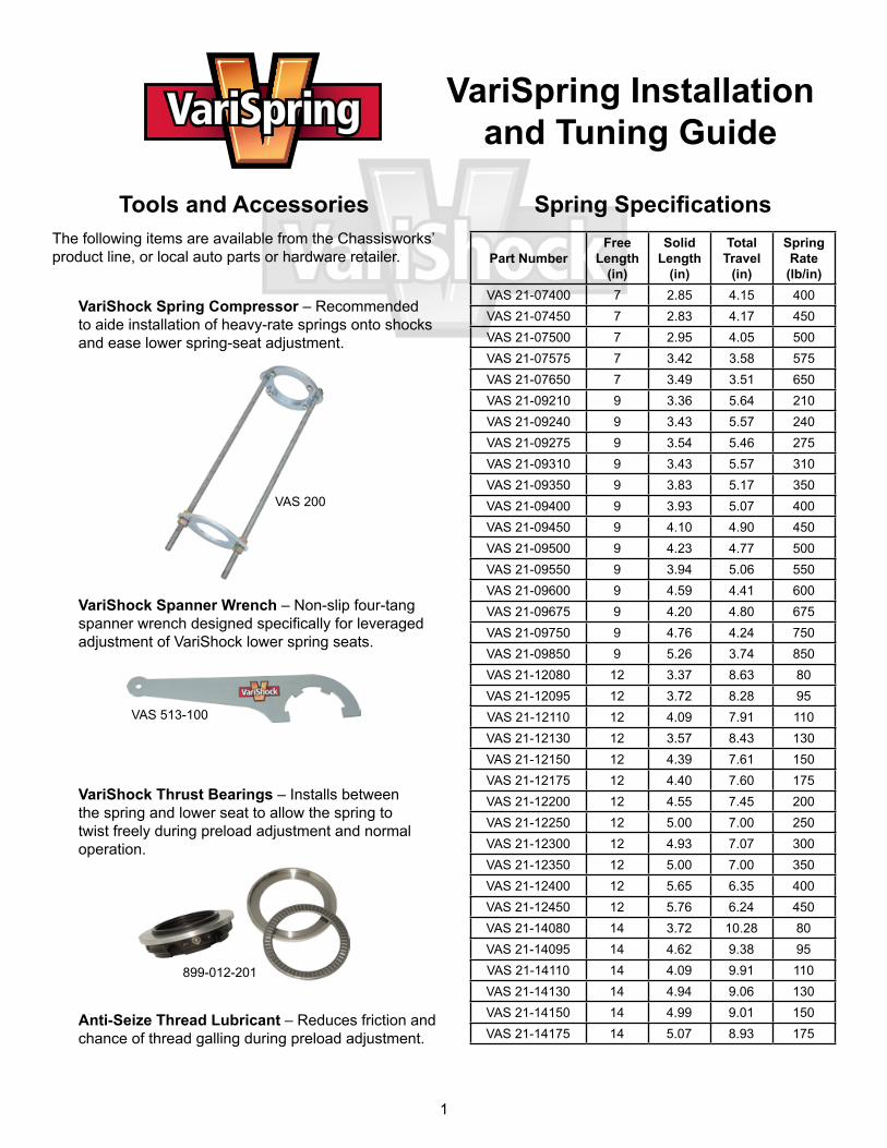
Spring Specifications
Part NumberFree
Length (in)
Solid Length
(in)
Total Travel
(in)
Spring Rate (lb/in)
VAS 21-07400 7 2.85 4.15 400VAS 21-07450 7 2.83 4.17 450VAS 21-07500 7 2.95 4.05 500VAS 21-07575 7 3.42 3.58 575VAS 21-07650 7 3.49 3.51 650VAS 21-09210 9 3.36 5.64 210VAS 21-09240 9 3.43 5.57 240VAS 21-09275 9 3.54 5.46 275VAS 21-09310 9 3.43 5.57 310VAS 21-09350 9 3.83 5.17 350VAS 21-09400 9 3.93 5.07 400VAS 21-09450 9 4.10 4.90 450VAS 21-09500 9 4.23 4.77 500VAS 21-09550 9 3.94 5.06 550VAS 21-09600 9 4.59 4.41 600VAS 21-09675 9 4.20 4.80 675VAS 21-09750 9 4.76 4.24 750VAS 21-09850 9 5.26 3.74 850VAS 21-12080 12 3.37 8.63 80VAS 21-12095 12 3.72 8.28 95VAS 21-12110 12 4.09 7.91 110VAS 21-12130 12 3.57 8.43 130VAS 21-12150 12 4.39 7.61 150VAS 21-12175 12 4.40 7.60 175VAS 21-12200 12 4.55 7.45 200VAS 21-12250 12 5.00 7.00 250VAS 21-12300 12 4.93 7.07 300VAS 21-12350 12 5.00 7.00 350VAS 21-12400 12 5.65 6.35 400VAS 21-12450 12 5.76 6.24 450VAS 21-14080 14 3.72 10.28 80VAS 21-14095 14 4.62 9.38 95VAS 21-14110 14 4.09 9.91 110VAS 21-14130 14 4.94 9.06 130VAS 21-14150 14 4.99 9.01 150VAS 21-14175 14 5.07 8.93 175
VariSpring Installation and Tuning Guide
Tools and AccessoriesThe following items are available from the Chassisworks’ product line, or local auto parts or hardware retailer.
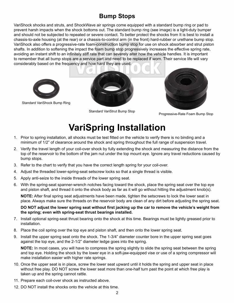
VariShock Spring Compressor – Recommended to aide installation of heavy-rate springs onto shocks and ease lower spring-seat adjustment.
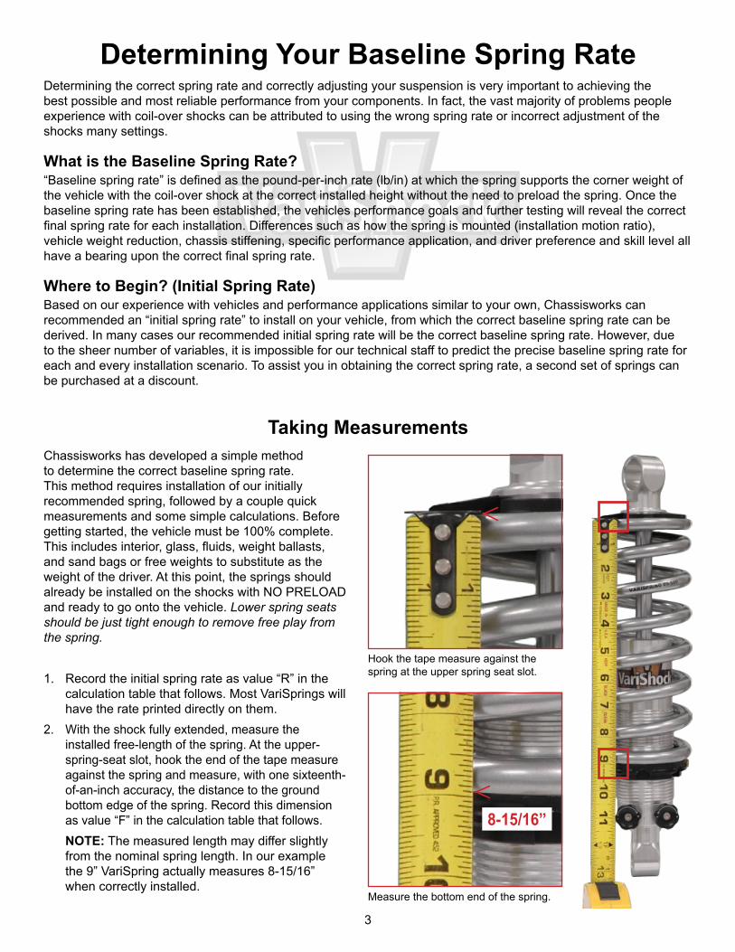
VariShock Spanner Wrench – Non-slip four-tang spanner wrench designed specifically for leveraged adjustment of VariShock lower spring seats.
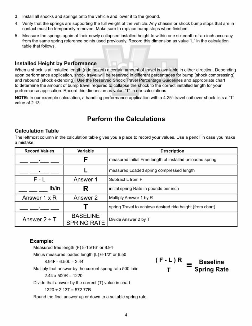
VariShock Thrust Bearings – Installs between the spring and lower seat to allow the spring to twist freely during preload adjustment and normal operation.
Anti-Seize Thread Lubricant – Reduces friction and chance of thread galling during preload adjustment.
VAS 200
VAS 513-100
899-012-201
2
Bump StopsVariShock shocks and struts, and ShockWave air springs come equipped with a standard bump ring or pad to prevent harsh impacts when the shock bottoms out. The standard bump ring (see image) is a light-duty bumper and should not be subjected to repeated or severe contact. To better protect the shocks from It is best to install a chassis-to-axle housing (at the rear) or a chassis-to-control arm (in the front) hard-rubber or urethane bump stop. VariShock also offers a progressive-rate foam-construction bump stop for use on shock absorber and strut piston shafts. In addition to softening the impact the foam bump stop progressively increases the effective spring rate, avoiding an instant shift to an infinitely stiff rate that can severely alter how the vehicle handles. It is important to remember that all bump stops are a service part and need to be replaced if worn. Their service life will vary considerably based on the frequency and how hard they are used.
VariSpring Installation1. Prior to spring installation, all shocks must be test fitted on the vehicle to verify there is no binding and a
minimum of 1/2” of clearance around the shock and spring throughout the full range of suspension travel.2. Verify the travel length of your coil-over shock by fully extending the shock and measuring the distance from the
top of the reservoir to the bottom of the jam nut under the top mount eye. Ignore any travel reductions caused by bump stops.
3. Refer to the chart to verify that you have the correct length spring for your coil-over.4. Adjust the threaded lower-spring-seat setscrew locks so that a single thread is visible.5. Apply anti-seize to the inside threads of the lower spring seat.6. With the spring-seat spanner-wrench notches facing toward the shock, place the spring seat over the top eye
and piston shaft, and thread it onto the shock body as far as it will go without hitting the adjustment knob(s).NOTE: After final spring seat adjustments have been made, tighten the setscrews to lock the lower seat in place. Always make sure the threads on the reservoir body are clean of any dirt before adjusting the spring seat. DO NOT adjust the lower spring seat without first jacking up the car to remove the vehicle’s weight from the spring; even with spring-seat thrust bearings installed.
7. Install optional spring-seat thrust bearing onto the shock at this time. Bearings must be lightly greased prior to installation.
8. Place the coil spring over the top eye and piston shaft, and then onto the lower spring seat.9. Install the upper spring seat onto the shock. The 1-3/4” diameter counter bore in the upper spring seat goes
against the top eye, and the 2-1/2” diameter ledge goes into the spring.NOTE: In most cases, you will have to compress the spring slightly to slide the spring seat between the spring and top eye. Holding the shock by the lower eye in a soft-jaw-equipped vise or use of a spring compressor will make installation easier with higher rate springs.
10. Once the upper seat is in place, screw the lower seat upward until it holds the spring and upper seat in place without free play. DO NOT screw the lower seat more than one-half turn past the point at which free play is taken up and the spring cannot rattle.
11. Prepare each coil-over shock as instructed above.12. DO NOT install the shocks onto the vehicle at this time.
Standard VariShock Bump Ring
Standard VariStrut Bump StopProgressive-Rate Foam Bump Stop
3
Measure the bottom end of the spring.
Hook the tape measure against the spring at the upper spring seat slot.
8-15/16”
Determining Your Baseline Spring RateDetermining the correct spring rate and correctly adjusting your suspension is very important to achieving the best possible and most reliable performance from your components. In fact, the vast majority of problems people experience with coil-over shocks can be attributed to using the wrong spring rate or incorrect adjustment of the shocks many settings.
What is the Baseline Spring Rate?“Baseline spring rate” is defined as the pound-per-inch rate (lb/in) at which the spring supports the corner weight of the vehicle with the coil-over shock at the correct installed height without the need to preload the spring. Once the baseline spring rate has been established, the vehicles performance goals and further testing will reveal the correct final spring rate for each installation. Differences such as how the spring is mounted (installation motion ratio), vehicle weight reduction, chassis stiffening, specific performance application, and driver preference and skill level all have a bearing upon the correct final spring rate.
Where to Begin? (Initial Spring Rate)Based on our experience with vehicles and performance applications similar to your own, Chassisworks can recommended an “initial spring rate” to install on your vehicle, from which the correct baseline spring rate can be derived. In many cases our recommended initial spring rate will be the correct baseline spring rate. However, due to the sheer number of variables, it is impossible for our technical staff to predict the precise baseline spring rate for each and every installation scenario. To assist you in obtaining the correct spring rate, a second set of springs can be purchased at a discount.
Taking MeasurementsChassisworks has developed a simple method to determine the correct baseline spring rate. This method requires installation of our initially recommended spring, followed by a couple quick measurements and some simple calculations. Before getting started, the vehicle must be 100% complete. This includes interior, glass, fluids, weight ballasts, and sand bags or free weights to substitute as the weight of the driver. At this point, the springs should already be installed on the shocks with NO PRELOAD and ready to go onto the vehicle. Lower spring seats should be just tight enough to remove free play from the spring.
1. Record the initial spring rate as value “R” in the calculation table that follows. Most VariSprings will have the rate printed directly on them.
2. With the shock fully extended, measure the installed free-length of the spring. At the upper-spring-seat slot, hook the end of the tape measure against the spring and measure, with one sixteenth-of-an-inch accuracy, the distance to the ground bottom edge of the spring. Record this dimension as value “F” in the calculation table that follows.NOTE: The measured length may differ slightly from the nominal spring length. In our example the 9” VariSpring actually measures 8-15/16” when correctly installed.
4
Example:Measured free length (F) 8-15/16” or 8.94Minus measured loaded length (L) 6-1/2” or 6.50 8.94F - 6.50L = 2.44Multiply that answer by the current spring rate 500 lb/in 2.44 x 500R = 1220Divide that answer by the correct (T) value in chart 1220 ÷ 2.13T = 572.77B Round the final answer up or down to a suitable spring rate.
3. Install all shocks and springs onto the vehicle and lower it to the ground.4. Verify that the springs are supporting the full weight of the vehicle. Any chassis or shock bump stops that are in
contact must be temporarily removed. Make sure to replace bump stops when finished.5. Measure the springs again at their newly collapsed installed height to within one sixteenth-of-an-inch accuracy
from the same spring reference points used previously. Record this dimension as value “L” in the calculation table that follows.
Installed Height by PerformanceWhen a shock is at installed length (ride height) a certain amount of travel is available in either direction. Depending upon performance application, shock travel will be reserved in different percentages for bump (shock compressing) and rebound (shock extending). Use the Reserved Shock Travel Percentage Guidelines and appropriate chart to determine the amount of bump travel required to collapse the shock to the correct installed length for your performance application. Record this dimension as value “T” in our calculations.NOTE: In our example calculation, a handling performance application with a 4.25”-travel coil-over shock lists a “T” value of 2.13.
Perform the Calculations
Calculation TableThe leftmost column in the calculation table gives you a place to record your values. Use a pencil in case you make a mistake.
Record Values Variable Description
__ __.__ __ F measured initial Free length of installed unloaded spring
__ __.__ __ L measured Loaded spring compressed length
F - L Answer 1 Subtract L from F
__ __ __ lb/in R initial spring Rate in pounds per inch
Answer 1 x R Answer 2 Multiply Answer 1 by R
__ __.__ __ T spring Travel to achieve desired ride height (from chart)
Answer 2 ÷ T BASELINE SPRING RATE
Divide Answer 2 by T
= ( F - L ) RT
Baseline Spring Rate
5
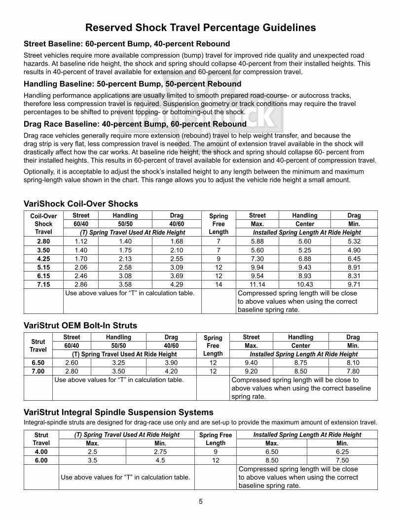
VariShock Coil-Over ShocksCoil-Over
Shock Travel
Street Handling Drag Spring Free
Length
Street Handling Drag60/40 50/50 40/60 Max. Center Min.
(T) Spring Travel Used At Ride Height Installed Spring Length At Ride Height2.80 1.12 1.40 1.68 7 5.88 5.60 5.323.50 1.40 1.75 2.10 7 5.60 5.25 4.904.25 1.70 2.13 2.55 9 7.30 6.88 6.455.15 2.06 2.58 3.09 12 9.94 9.43 8.916.15 2.46 3.08 3.69 12 9.54 8.93 8.317.15 2.86 3.58 4.29 14 11.14 10.43 9.71
Use above values for “T” in calculation table. Compressed spring length will be close to above values when using the correct baseline spring rate.
VariStrut OEM Bolt-In Struts
Strut Travel
Street Handling Drag Spring Free
Length
Street Handling Drag60/40 50/50 40/60 Max. Center Min.
(T) Spring Travel Used At Ride Height Installed Spring Length At Ride Height6.50 2.60 3.25 3.90 12 9.40 8.75 8.107.00 2.80 3.50 4.20 12 9.20 8.50 7.80
Use above values for “T” in calculation table. Compressed spring length will be close to above values when using the correct baseline spring rate.
VariStrut Integral Spindle Suspension SystemsIntegral-spindle struts are designed for drag-race use only and are set-up to provide the maximum amount of extension travel.
Strut Travel
(T) Spring Travel Used At Ride Height Spring Free Length
Installed Spring Length At Ride HeightMax. Min. Max. Min.
4.00 2.5 2.75 9 6.50 6.256.00 3.5 4.5 12 8.50 7.50
Use above values for “T” in calculation table.Compressed spring length will be close to above values when using the correct baseline spring rate.
Reserved Shock Travel Percentage GuidelinesStreet Baseline: 60-percent Bump, 40-percent ReboundStreet vehicles require more available compression (bump) travel for improved ride quality and unexpected road hazards. At baseline ride height, the shock and spring should collapse 40-percent from their installed heights. This results in 40-percent of travel available for extension and 60-percent for compression travel.
Handling Baseline: 50-percent Bump, 50-percent ReboundHandling performance applications are usually limited to smooth prepared road-course- or autocross tracks, therefore less compression travel is required. Suspension geometry or track conditions may require the travel percentages to be shifted to prevent topping- or bottoming-out the shock.
Drag Race Baseline: 40-percent Bump, 60-percent Rebound Drag race vehicles generally require more extension (rebound) travel to help weight transfer, and because the drag strip is very flat, less compression travel is needed. The amount of extension travel available in the shock will drastically affect how the car works. At baseline ride height, the shock and spring should collapse 60- percent from their installed heights. This results in 60-percent of travel available for extension and 40-percent of compression travel.Optionally, it is acceptable to adjust the shock’s installed height to any length between the minimum and maximum spring-length value shown in the chart. This range allows you to adjust the vehicle ride height a small amount.
6
VariSpring Adjustment and Tuning GuideOnce the baseline spring rate has been determined, you are better prepared to make decisions with regards to changing spring rates for the purpose of tuning the suspension. Suspension tuning involves multiple variables such as: spring rates, anti-roll-bar rates, vehicle weight distribution, tire sizes, tire pressures, suspension geometry, and track conditions. The information contained in this tuning guide covers basic tuning procedures and has been greatly simplified to get you started in the right direction. We strongly recommend researching suspension tuning and vehicle dynamics, or consulting an experienced professional for further understanding of the pros and cons of making each adjustment.
Tuning CategoriesVariSpring’s broad range of spring rates and lengths are suitable to the three categories of suspension tuning: Ride Quality, Handling Performance, and Drag Racing. All three tuning categories have the common goal of controlled weight transfer, but have greatly differing vehicle-dynamic requirements. Each will be discussed in the following text. Before proceeding verify that all suspension components, such as control arms, balljoints, and bushings are in acceptable condition and that tire pressures are correctly set.
Correcting Shock Installed LengthThreaded spring seats allow installation of spring rates that differ from the baseline spring rate for the purpose of performance tuning. With the spring free from the weight of the vehicle and the shock at full extension, spring seats can be threaded up or down to keep the shock at the correct collapsed install height. Raising the spring seat to compress the coil spring to any length shorter than it’s free height, with the shock fully extended, is referred to as preloading the spring. During the tuning process if you elect to use a coil spring that is lighter than the calculated baseline spring rate, it may be necessary to add preload to achieve the correct balance of travel and ride height. If preload has been added make sure there is adequate spring travel remaining to prevent coil bind before the shock is fully collapsed.
Raising or Lowering Ride HeightThe spring seats are not intended to alter the vehicle’s ground clearance beyond the allowed range of ride-height shock lengths. Altering ride height in this manner, risks damaging the shocks due to the lack of reserved travel in either direction. Other options for altering the vehicle’s ground clearance must be empolyed. Then include moving the upper or lower shock mount, changing to a different length shock, or changing tire diameter.
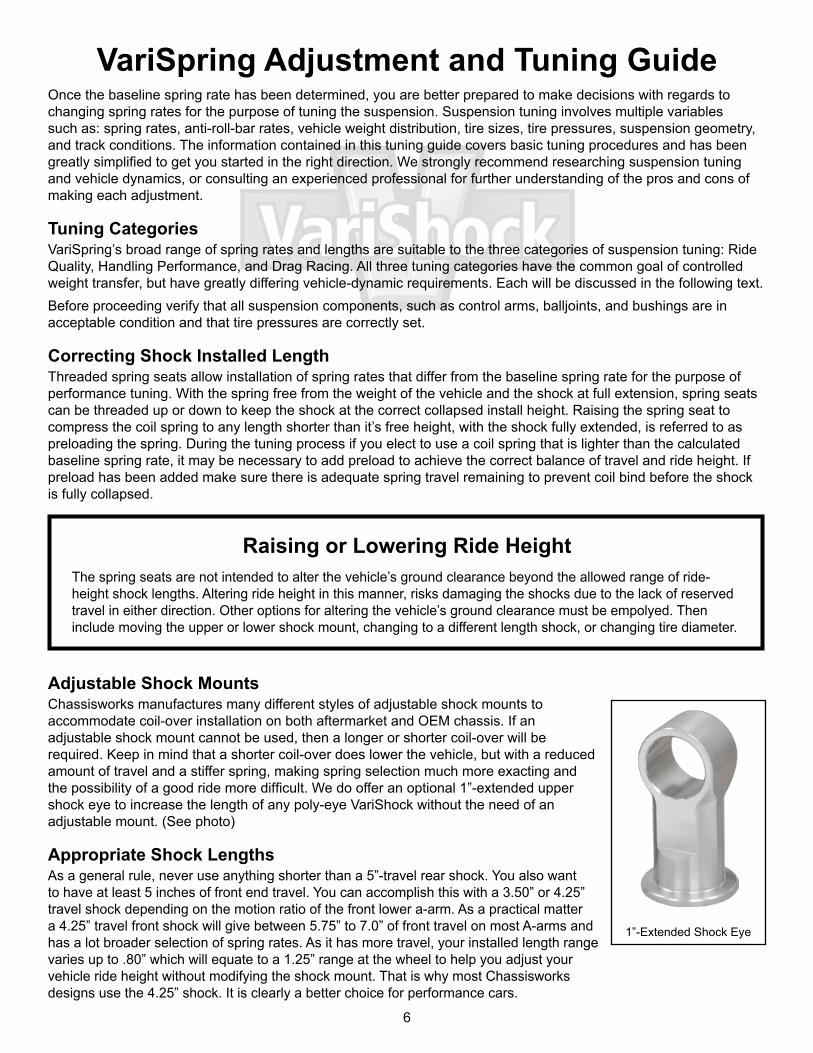
Adjustable Shock MountsChassisworks manufactures many different styles of adjustable shock mounts to accommodate coil-over installation on both aftermarket and OEM chassis. If an adjustable shock mount cannot be used, then a longer or shorter coil-over will be required. Keep in mind that a shorter coil-over does lower the vehicle, but with a reduced amount of travel and a stiffer spring, making spring selection much more exacting and the possibility of a good ride more difficult. We do offer an optional 1”-extended upper shock eye to increase the length of any poly-eye VariShock without the need of an adjustable mount. (See photo)
Appropriate Shock Lengths As a general rule, never use anything shorter than a 5”-travel rear shock. You also want to have at least 5 inches of front end travel. You can accomplish this with a 3.50” or 4.25” travel shock depending on the motion ratio of the front lower a-arm. As a practical matter a 4.25” travel front shock will give between 5.75” to 7.0” of front travel on most A-arms and has a lot broader selection of spring rates. As it has more travel, your installed length range varies up to .80” which will equate to a 1.25” range at the wheel to help you adjust your vehicle ride height without modifying the shock mount. That is why most Chassisworks designs use the 4.25” shock. It is clearly a better choice for performance cars.
1”-Extended Shock Eye
7
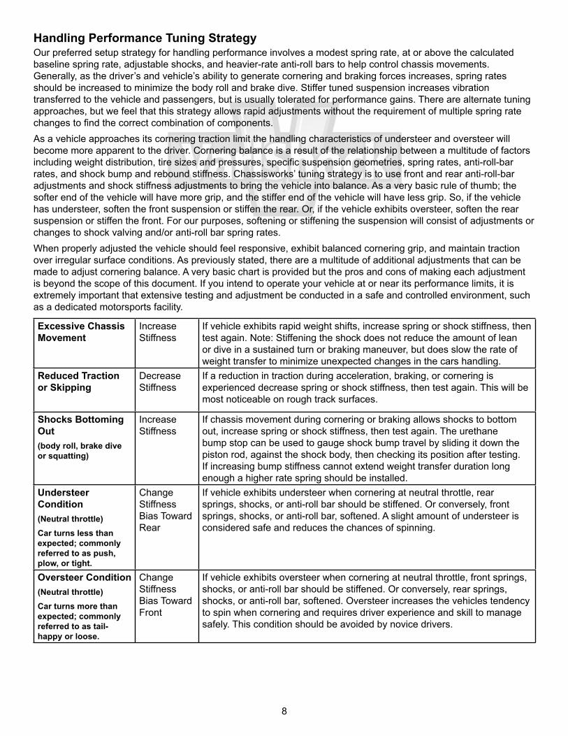
Tuning for Ride QualityTuning for ride quality generally involves spring rates that are at or slightly below the baseline spring rate, matched with softer shock settings to achieve a smooth and comfortable ride. Use of adjustable shocks allows softer settings for regular street use that can easily be changed to a stiffer setting for mild performance use. When properly adjusted for street use the vehicle should feel settled without continued bouncing (too soft), excessive harshness (too stiff), or fore/aft pitching. The vehicle’s cornering ability can be improved with the addition of a moderately-sized front anti-roll bar. A moderate-size anti-roll bar will reduce body roll during cornering without increasing ride harshness over uneven surfaces. We feel that this general approach yields a comfortable driving vehicle that can be easily moved toward more performance oriented driving when used with adjustable shocks. Testing and adjustment is required to attain desirable results.
Shocks Topping- or Bottoming-Out
Increase Stiffness
If the shocks are within their allowed installed-height range and repeatedly exceed the travel limits of the shock, increase spring rates or shock stiffness to reduce the amount of suspension travel.
Excessive Chassis Movement
Increase Stiffness
If vehicle exhibits rapid weight shifts or continues to oscillate more than one suspension cycle before settling, increase spring or shock stiffness, then test again. As stiffness is increased, road noise and vibration will also increase. Note: Stiffening the shock does not reduce the amount of lean or dive in a sustained turn or braking maneuver, but does slow the rate of weight transfer to minimize unexpected changes in the cars handling.
Harshness and Vibration
Decrease Stiffness
If excessive road noise, vibration, or harshness is experienced decrease spring or shock stiffness, then test again.
Fore/Aft Pitching(constant speed 50-70 mph)
Alter Front-to-Rear Stiffness Difference
If vehicle exhibits fore/aft pitching at highway speeds, the rear springs or shocks should be stiffened or conversely the front springs or shocks softened. Ideally the rear suspension should oscillate at a slightly quicker rate than the front to minimize pitching.
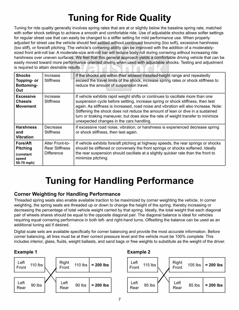
Tuning for Handling PerformanceCorner Weighting for Handling PerformanceThreaded spring seats also enable available traction to be maximized by corner weighting the vehicle. In corner weighting, the spring seats are threaded up or down to change the height of the spring, thereby increasing or decreasing the percentage of total vehicle weight carried by that spring. Ideally, the total weight that each diagonal pair of wheels shares should be equal to the opposite diagonal pair. The diagonal balance is ideal for vehicles requiring equal cornering performance in both left- and right-hand turns. Offsetting the balance can be used as an additional tuning aid if desired.Digital scale sets are available specifically for corner balancing and provide the most accurate information. Before corner balancing, all tires must be at their correct pressure level and the vehicle must be 100% complete. This includes interior, glass, fluids, weight ballasts, and sand bags or free weights to substitute as the weight of the driver.
Left Front 110 lbs Right
Front 110 lbs = 200 lbs
Left Rear 90 lbs Left
Rear 90 lbs = 200 lbs
Left Front 115 lbs Right
Front 105 lbs = 200 lbs
Left Rear 95 lbs Left
Rear 85 lbs = 200 lbs
Example 1 Example 2
8
Handling Performance Tuning StrategyOur preferred setup strategy for handling performance involves a modest spring rate, at or above the calculated baseline spring rate, adjustable shocks, and heavier-rate anti-roll bars to help control chassis movements. Generally, as the driver’s and vehicle’s ability to generate cornering and braking forces increases, spring rates should be increased to minimize the body roll and brake dive. Stiffer tuned suspension increases vibration transferred to the vehicle and passengers, but is usually tolerated for performance gains. There are alternate tuning approaches, but we feel that this strategy allows rapid adjustments without the requirement of multiple spring rate changes to find the correct combination of components.As a vehicle approaches its cornering traction limit the handling characteristics of understeer and oversteer will become more apparent to the driver. Cornering balance is a result of the relationship between a multitude of factors including weight distribution, tire sizes and pressures, specific suspension geometries, spring rates, anti-roll-bar rates, and shock bump and rebound stiffness. Chassisworks’ tuning strategy is to use front and rear anti-roll-bar adjustments and shock stiffness adjustments to bring the vehicle into balance. As a very basic rule of thumb; the softer end of the vehicle will have more grip, and the stiffer end of the vehicle will have less grip. So, if the vehicle has understeer, soften the front suspension or stiffen the rear. Or, if the vehicle exhibits oversteer, soften the rear suspension or stiffen the front. For our purposes, softening or stiffening the suspension will consist of adjustments or changes to shock valving and/or anti-roll bar spring rates. When properly adjusted the vehicle should feel responsive, exhibit balanced cornering grip, and maintain traction over irregular surface conditions. As previously stated, there are a multitude of additional adjustments that can be made to adjust cornering balance. A very basic chart is provided but the pros and cons of making each adjustment is beyond the scope of this document. If you intend to operate your vehicle at or near its performance limits, it is extremely important that extensive testing and adjustment be conducted in a safe and controlled environment, such as a dedicated motorsports facility.
Excessive Chassis Movement
Increase Stiffness
If vehicle exhibits rapid weight shifts, increase spring or shock stiffness, then test again. Note: Stiffening the shock does not reduce the amount of lean or dive in a sustained turn or braking maneuver, but does slow the rate of weight transfer to minimize unexpected changes in the cars handling.
Reduced Traction or Skipping
Decrease Stiffness
If a reduction in traction during acceleration, braking, or cornering is experienced decrease spring or shock stiffness, then test again. This will be most noticeable on rough track surfaces.
Shocks Bottoming Out(body roll, brake dive or squatting)
Increase Stiffness
If chassis movement during cornering or braking allows shocks to bottom out, increase spring or shock stiffness, then test again. The urethane bump stop can be used to gauge shock bump travel by sliding it down the piston rod, against the shock body, then checking its position after testing. If increasing bump stiffness cannot extend weight transfer duration long enough a higher rate spring should be installed.
Understeer Condition(Neutral throttle)Car turns less than expected; commonly referred to as push, plow, or tight.
Change Stiffness Bias Toward Rear
If vehicle exhibits understeer when cornering at neutral throttle, rear springs, shocks, or anti-roll bar should be stiffened. Or conversely, front springs, shocks, or anti-roll bar, softened. A slight amount of understeer is considered safe and reduces the chances of spinning.
Oversteer Condition(Neutral throttle)Car turns more than expected; commonly referred to as tail-happy or loose.
Change Stiffness Bias Toward Front
If vehicle exhibits oversteer when cornering at neutral throttle, front springs, shocks, or anti-roll bar should be stiffened. Or conversely, rear springs, shocks, or anti-roll bar, softened. Oversteer increases the vehicles tendency to spin when cornering and requires driver experience and skill to manage safely. This condition should be avoided by novice drivers.
9
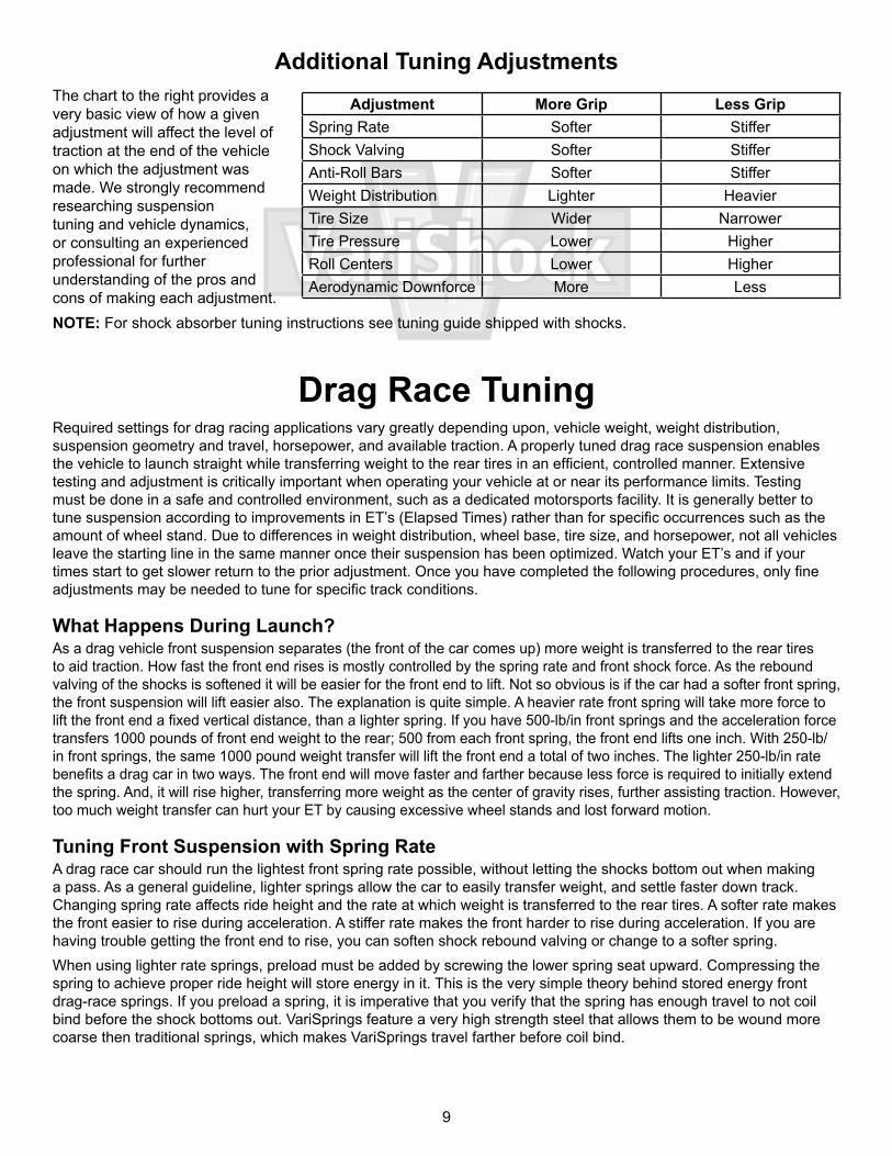
Additional Tuning AdjustmentsThe chart to the right provides a very basic view of how a given adjustment will affect the level of traction at the end of the vehicle on which the adjustment was made. We strongly recommend researching suspension tuning and vehicle dynamics, or consulting an experienced professional for further understanding of the pros and cons of making each adjustment.NOTE: For shock absorber tuning instructions see tuning guide shipped with shocks.
Drag Race TuningRequired settings for drag racing applications vary greatly depending upon, vehicle weight, weight distribution, suspension geometry and travel, horsepower, and available traction. A properly tuned drag race suspension enables the vehicle to launch straight while transferring weight to the rear tires in an efficient, controlled manner. Extensive testing and adjustment is critically important when operating your vehicle at or near its performance limits. Testing must be done in a safe and controlled environment, such as a dedicated motorsports facility. It is generally better to tune suspension according to improvements in ET’s (Elapsed Times) rather than for specific occurrences such as the amount of wheel stand. Due to differences in weight distribution, wheel base, tire size, and horsepower, not all vehicles leave the starting line in the same manner once their suspension has been optimized. Watch your ET’s and if your times start to get slower return to the prior adjustment. Once you have completed the following procedures, only fine adjustments may be needed to tune for specific track conditions.
What Happens During Launch?As a drag vehicle front suspension separates (the front of the car comes up) more weight is transferred to the rear tires to aid traction. How fast the front end rises is mostly controlled by the spring rate and front shock force. As the rebound valving of the shocks is softened it will be easier for the front end to lift. Not so obvious is if the car had a softer front spring, the front suspension will lift easier also. The explanation is quite simple. A heavier rate front spring will take more force to lift the front end a fixed vertical distance, than a lighter spring. If you have 500-lb/in front springs and the acceleration force transfers 1000 pounds of front end weight to the rear; 500 from each front spring, the front end lifts one inch. With 250-lb/in front springs, the same 1000 pound weight transfer will lift the front end a total of two inches. The lighter 250-lb/in rate benefits a drag car in two ways. The front end will move faster and farther because less force is required to initially extend the spring. And, it will rise higher, transferring more weight as the center of gravity rises, further assisting traction. However, too much weight transfer can hurt your ET by causing excessive wheel stands and lost forward motion.
Tuning Front Suspension with Spring RateA drag race car should run the lightest front spring rate possible, without letting the shocks bottom out when making a pass. As a general guideline, lighter springs allow the car to easily transfer weight, and settle faster down track. Changing spring rate affects ride height and the rate at which weight is transferred to the rear tires. A softer rate makes the front easier to rise during acceleration. A stiffer rate makes the front harder to rise during acceleration. If you are having trouble getting the front end to rise, you can soften shock rebound valving or change to a softer spring. When using lighter rate springs, preload must be added by screwing the lower spring seat upward. Compressing the spring to achieve proper ride height will store energy in it. This is the very simple theory behind stored energy front drag-race springs. If you preload a spring, it is imperative that you verify that the spring has enough travel to not coil bind before the shock bottoms out. VariSprings feature a very high strength steel that allows them to be wound more coarse then traditional springs, which makes VariSprings travel farther before coil bind.
Adjustment More Grip Less GripSpring Rate Softer StifferShock Valving Softer StifferAnti-Roll Bars Softer StifferWeight Distribution Lighter HeavierTire Size Wider NarrowerTire Pressure Lower HigherRoll Centers Lower HigherAerodynamic Downforce More Less
10
In general terms, the worse a car hooks, the more shock extension travel it will need. If you need more extension travel, preload can be removed to lower ride height. Using this method will cause the car to have less ground clearance and reduce the amount of compression travel. If you are going to operate the shock at a ride height shorter than recommended, the upper chassis mounts must be relocated to correct any major vehicle ride height issues. It may take some work with spring rates and upper mount relocation to get the correct combination of vehicle ride height and front suspension travel for your application.
Prior to TestingMake certain that wheelie bars are raised as high as possible while maintaining control and eliminating their influence as much as possible on suspension settings.
Initial TestingFirst verify that the vehicle tracks straight before aggressively launching from the line. Begin with light acceleration and low speeds. If the vehicle tracks and drives acceptably at this level, make incremental increases in acceleration and top speed until the vehicle is safe at higher speed. Vehicles not tracking straight at speed should verify all chassis settings including but not limited to alignment, bump steer, tire pressures, etc. Once the vehicle drives in a safe manner at speed, move on to test launching.Test launches should consist of only the initial launch with no subsequent gear changes. Begin with low rpm launches and gradually increase rpm and severity if the car launches acceptably. At this time we are only determining that the car launches in a controlled manner to avoid damaging components or the vehicle. The vehicle should leave in a straight line without extreme wheel standing or harsh bounces. Sudden, uncontrollable front end lift should be corrected by making suspension instant center adjustments, if possible. More gradual front end lift can be corrected by adjusting the shock valving, if possible. If the car gradually wheel stands or bounces violently, adjust front suspension first, then rear. If there is rear tire shake, wheel hop or excessive body separation, adjust rear suspension first, then front. After the car has been adjusted to launch straight, test launch and include the first gear change. Make any required adjustments and add the next gear change. Repeat until the car can be launched straight and driven at speed safely. The car is now ready for fine tuning to optimum results.
Front Shock AdjustmentPay close attention to what is happening to the front end during launch. Your goal is to eliminate all jerking or bouncing movements during launch and gear shifts. Ideally the front end should rise in a controlled manner, just enough to keep the rear tires loaded, then continue the pass with smooth transitions at all times. Front end rise without any appreciable traction gain is wasted energy that should be used to propel the vehicle forward instead of up. While testing, document your ET’s along with any changes made. If ET does not improve, return to previous settings.
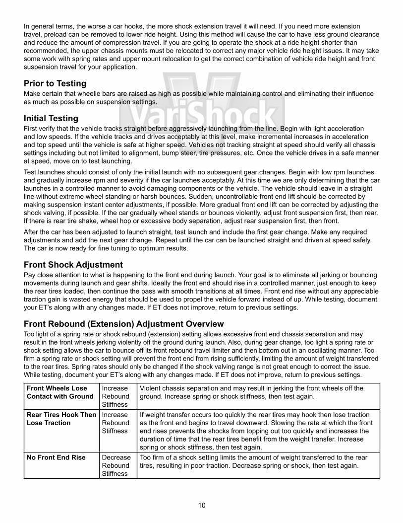
Front Rebound (Extension) Adjustment OverviewToo light of a spring rate or shock rebound (extension) setting allows excessive front end chassis separation and may result in the front wheels jerking violently off the ground during launch. Also, during gear change, too light a spring rate or shock setting allows the car to bounce off its front rebound travel limiter and then bottom out in an oscillating manner. Too firm a spring rate or shock setting will prevent the front end from rising sufficiently, limiting the amount of weight transferred to the rear tires. Spring rates should only be changed if the shock valving range is not great enough to correct the issue. While testing, document your ET’s along with any changes made. If ET does not improve, return to previous settings.
Front Wheels Lose Contact with Ground
Increase Rebound Stiffness
Violent chassis separation and may result in jerking the front wheels off the ground. Increase spring or shock stiffness, then test again.
Rear Tires Hook Then Lose Traction
Increase Rebound Stiffness
If weight transfer occurs too quickly the rear tires may hook then lose traction as the front end begins to travel downward. Slowing the rate at which the front end rises prevents the shocks from topping out too quickly and increases the duration of time that the rear tires benefit from the weight transfer. Increase spring or shock stiffness, then test again.
No Front End Rise Decrease Rebound Stiffness
Too firm of a shock setting limits the amount of weight transferred to the rear tires, resulting in poor traction. Decrease spring or shock, then test again.
11
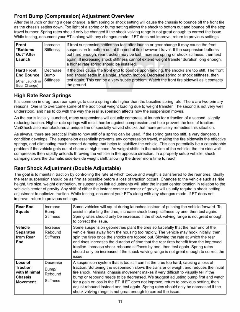
Front Bump (Compression) Adjustment OverviewAfter the launch or during a gear change, a firm spring or shock setting will cause the chassis to bounce off the front tire as the chassis settles down. Too light of a spring or bump setting allows the shock to bottom out and bounce off the stop travel bumper. Spring rates should only be changed if the shock valving range is not great enough to correct the issue. While testing, document your ET’s along with any changes made. If ET does not improve, return to previous settings.
Front “Bottoms Out“ After Launch
Increase Stiffness
If front suspension settles too fast after launch or gear change it may cause the front suspension to bottom out at the end of its downward travel. If the suspension bottoms out hard enough, rear traction may be lost. Increase spring or shock stiffness, then test again. If increasing shock stiffness cannot extend weight transfer duration long enough, a higher rate spring should be installed.
Hard Front End Bounce(After Launch or Gear Change)
Decrease Bump Stiffness
If the tires cause the front end to bounce upon landing, the shocks are too stiff. The front end should settle in a single, smooth motion. Decrease spring or shock stiffness, then test again. This can be a very subtle problem. Watch the front tire sidewall as it contacts the ground.
High Rate Rear SpringsIt is common in drag race rear springs to use a spring rate higher than the baseline spring rate. There are two primary reasons. One is to overcome some of the additional weight loading due to weight transfer. The second is not very well understood, and has to do with the way the rear suspension affects how the suspension moves. As the car is initially launched, many suspensions will actually compress at launch for a fraction of a second, slightly reducing traction. Higher rate springs will resist harder against compression and help prevent the loss of traction. VariShock also manufactures a unique line of specially valved shocks that more precisely remedies this situation. As always, there are practical limits to how stiff of a spring can be used. If the spring gets too stiff, a very dangerous condition develops. The suspension essentially prevents any compression travel, making the tire sidewalls the effective springs, and eliminating much needed damping that helps to stabilize the vehicle. This can potentially be a catastrophic problem if the vehicle gets out of shape at high speed. As weight shifts to the outside of the vehicle, the tire side wall compresses then rapidly unloads throwing the vehicle in the opposite direction. In a properly setup vehicle, shock damping slows the dramatic side-to-side weight shift, allowing the driver more time to react.
Rear Shock Adjustment (Double Adjustable)The goal is to maintain traction by controlling the rate at which torque and weight is transferred to the rear tires. Ideally the rear suspension should be as firm as possible before a loss of traction occurs. Changes to the vehicle such as ride height, tire size, weight distribution, or suspension link adjustments will alter the instant center location in relation to the vehicle’s center of gravity. Any shift of either the instant center or center of gravity will usually require a shock setting adjustment to optimize traction. While testing, document your ET’s along with any changes made. If ET does not improve, return to previous settings.
Rear End Squats
Increase Bump Stiffness
Some vehicles will squat during launches instead of pushing the vehicle forward. To assist in planting the tires, increase shock bump stiffness by one, then test again. Spring rates should only be increased if the shock valving range is not great enough to correct the issue.
Vehicle Separates from Rear End
Increase Rebound Stiffness
Some suspension geometries plant the tires so forcefully that the rear end of the vehicle rises away from the housing too rapidly. The vehicle may hook initially, then spin the tires once the shocks are topped out. Slowing the rate at which the rear end rises increases the duration of time that the rear tires benefit from the improved traction. Increase shock rebound stiffness by one, then test again. Spring rates should only be increased if the shock valving range is not great enough to correct the issue.
Loss of Traction with Minimal Chassis Movement
DecreaseBump/ReboundStiffness
A suspension system that is too stiff can hit the tires too hard, causing a loss of traction. Softening the suspension slows the transfer of weight and reduces the initial tire shock. Minimal chassis movement makes if very difficult to visually tell if the bump or rebound needs to be decreased. We suggest adjusting bump first and watch for a gain or loss in the ET. If ET does not improve, return to previous setting, then adjust rebound instead and test again. Spring rates should only be decreased if the shock valving range is not great enough to correct the issue.
12
Chris Alston’s Chassisworks8661 Younger Creek DriveSacramento, CA 95828Phone: 916-388-0288Technical Support: [email protected]
899-031-215 REV 06/22/09
WARRANTY NOTICE:There are NO WARRANTIES, either expressed or implied. Neither the seller nor manufacturer will be liable for any loss, damage or injury, direct or indirect, arising from the use or inability to determine the appropriate use of any products. Before any attempt at installation, all drawings and/or instruction sheets should be completely reviewed to determine the suitability of the product for its intended use. In this connection, the user assumes all responsibility and risk. We reserve the right to change specification without notice. Further, Chris Alston’s Chassisworks, Inc., makes NO GUARANTEE in reference to any specific class legality of any component. ALL PRODUCTS ARE INTENDED FOR RACING AND OFF-ROAD USE AND MAY NOT BE LEGALLY USED ON THE HIGHWAY. The products offered for sale are true race-car components and, in all cases, require some fabrication skill. NO PRODUCT OR SERVICE IS DESIGNED OR INTENDED TO PREVENT INJURY OR DEATH.
Completion of TestingWhen all adjustments have been completed, reset your wheelie bars as low as possible without affecting your ET.