Embed Size (px)
Citation preview

8/12/2019 various papers in our college
http://slidepdf.com/reader/full/various-papers-in-our-college 1/69
Proceedings of the Seventh NCVIT7th March 2014 GCT,Coimbatore
To Enhance the Lifetime of WSN
Network using PSO
K.SyedAliFathima, T.Sumitha,Assistant Professor, PG Student,M. Kumarasamy College of engineering, M.Kumarasamy College of engineering,Karur. Karur.
.Abstract — The major issues in wireless sensor networks is
to maximize the network lifetime of sensors.The best
energy efficient protocol is LEACH to reduce the energy
consumption and it can extend the lifetime of wireless
sensor network.Clustering techniques can be used to
communicate with cluster-head and base station. If thebase station is far away from the cluster-head ,energy
consumption will be increased and it can reduce the
lifetime of wireless sensor network.To overcome these,
Paticle swarm Optimization technique is implemented
with this protocol inorder to achieve maximum lifetime of
wireless sensor network.PSO is used to extend the scalable
and energy efficiency. It is easy to implement and the
mutation calculation speed is very fast.
Keywords —
Low Energy Adaptive ClusteringHierarchy (LEACH) , Wireless Sensor Networks (WSNs) ,
Partical Swarm Optimization(PSO) ,Energy efficiency
and Cluster methods .
I.INTRODUCTION
A wireless sensor network consists of a large numberof sensor nodes and it can be used as an effective tool for
collecting data from various situations. The major issue inwireless sensor networks is developing an energy-efficientrouting protocol which has a significant impact on the overalllifetime of the sensor network.
The wireless sensor networks consist of morenumber of nodes and that nodes are transfer the informationfrom source to sink or base station. The components of sensornetworks are sensor nodes, sink, base station and sensor field.
Fig 1: Wireless sensor networks
Network routing protocols are in charge of routing scheme aswell as maintaining the network structure in WSNs. There arethree types of network structure: flat routing, hierarchicalrouting and location-based routing [4]. In wireless sensornetwork, LEACH protocol is one of the best energy efficient
protocol. It helps to reduce the energy dissipation and it is a
first hierarchical based network routing protocol. Hierarchicalrouting is mainly considered as two layer architecture.Therefore, one layer is engaged in cluster head selection andthe other layer is responsible for routing.
LEACH uses a clustering method to reduce theenergy consumption and it arranges the nodes in network assmall clusters and it select one as cluster head (CH). It
provides the balancing of energy usage by random rotation ofcluster heads. LEACH protocol uses a data fusion algorithm
for reduce the data transmission. Cluster head are used tocompress and reduce the information where received from allnodes and sends it to the sink.
LEACH operations are divided into two phases:
1. Setup phase2. Steady phase

8/12/2019 various papers in our college
http://slidepdf.com/reader/full/various-papers-in-our-college 2/69
Proceedings of the Seventh NCVIT7th March 2014 GCT,Coimbatore
Fig 2: Clustering methods
In setup phase , each node is independent of othernode. Then it will form cluster and cluster head(CH) ischosen for each cluster. Setup phase are used to minimize theoverhead cost. During steady phase, the sensor nodes the non-cluster head nodes starts sensing data and sends it to theircluster-head according to the TDM schedule. The cluster-headnode, after receiving data from all the member nodes,aggregates it and then sends it to the base-station . SteadyPhase consists of Schedule Creation and Data Transmission.LEACH protocol periodically elects the cluster head nodesand re-establishes the clusters according to a round time,which ensures energy dissipation of each node in the network
is relatively evenly [3].
II.OVERVIEW
In this section, the LEACH protocol and PSOtechniques are explained.
LEACH PROTOCOL:
Wireless sensor networks is used for developing arouting protocol, has a significant impact on overall lifetimeof the sensor network which employs a new technique ofLEACH protocol called VLEACH.The central role is toreduce energy consumption in sensor network.LEACH
performs self-organizing and re-clustering functions for everyround [2][8]. Sensor nodes organize themselves into clustersin LEACH routing protocol. LEACH-E proposed to elect thecluster-heads according to the energy left in each node.[11] Inevery cluster one of the sensor node acts as cluster-head andremaining sensor nodes as member nodes of that cluster. OnlyCluster-head can directly communicate to sink and membernodes use cluster-head as intermediate router in case ofcommunication to sink.
The potential problem in current protocols is thatthey find the lowest energy route and use that for every
communication. We propose a new protocol that we callenergy aware routing. This is used to increase the survivabilityof networks. Additionally, these sensor nodes have limited
processing power, storage and energy, while the sink nodeshave powerful resources to perform any tasks or communicate
with the sensor nodes.. Then we propose a heuristic routingalgorithm to achieve our design goal. The algorithm works inthe following way. First, we compute the network throughput,which is the most important performance metric for data-intensive computations, according to the routing on all datacentre switches. The corresponding routing is called basicrouting. Second, we gradually remove switches from the basicrouting, until when the network throughput decreases to a
predefined performance threshold. Third, switches notinvolved in the final routing are powered off or put into sleepmode. However, to save energy, sensor nodes send theirmessages to their CHs, which then aggregate the messages,and send the aggregate to the BS. However, because it is acluster based protocol, relying fundamentally on the CHs fordata aggregation and routing, attacks involving CHs are themost damaging. If an intruder manages to become a CH, it canstage attacks such as sinkhole and selective forwarding, thusdisrupting the workings of the network. To overcome thedisadvantages of LEACH protocol, PSO technique isemployed.
PARTICLE SWARM OPTIMIZATION (PSO):
Particle swarm optimization (PSO) is a simple,effective and efficient optimization algorithm. PSO is used toexplore the search place. It is easy to implement and it can beapplied for both scientific research and engineering use.
In PSO, a global fitness function is used by all the particles in the swarm. In this, No overlapping and mutationcalculation speed is very fast. It evaluates the fitness of each
particle. It occupies the bigger optimization ability and itcomplete easily. Particles in traditional PSO represent thecandidate solutions to a single optimization problem. [5]. theenergy consumption and reliability are taken into an accounttopology control is the problem of LEACH protocol. The
binary particle swarm optimization (BPSO) approach to solvethe disjoint set covers (DSC) problem in the wireless sensornetworks (WSN). The DSC problem is to divide the sensornodes into different disjoint sets and schedule them to workone by one in order to save energy while at the same timemeets the surveillance requirement, e.g., the full coverageobjective of DSC is to maximal the number of disjoint. PSO
based algorithm is used to locate the optimal sink position tothe nodes to make the network is more energy efficient.
Some of the techniques are used to improve thenetwork lifetime of wireless sensor network:
Data fusion algorithm. Energy-efficient routing.
8/12/2019 various papers in our college
http://slidepdf.com/reader/full/various-papers-in-our-college 3/69
Proceedings of the Seventh NCVIT7th March 2014 GCT,Coimbatore
Locating optimal sink position.PSO is more robust and easy to reach the solution for realworld environmental monitoring and data aggregation
problems.
Fig: Particle swarm optimization.
III. ENERGY ANALYSIS
Energy analysis of routing protocol are as follows:Sensor sends the data directly to sink. If the sink is far away,large amount of transmit power from each note will quicklydrain nodes and it reduce system lifetime. By using routing
protocol each node is acts as routers for other node's data inaddition to sensing data. And this protocol is used to neglect
energy dissipation of receiver intermediate nodes. Whilecreating the infrastructure, the process of setting up the routesis greatly influenced by energy considerations. The multihoprouting will consume less energy. So multi-hop routingintroduces significant overhead for topology management andmedium access control. In sometime sensors are scatteredrandomly over an area and multi-hop routing becomesunavoidable [13] for large area energy consumptions,Improved FZ-LEACH has been introduced.
A.IMPROVED FZ-LEACH:
For large scale deployments, very small clusters does
not provide energy efficiently. So, it decreases the networklifetime of wireless sensor network. The new energy efficientclustering protocol is Improved FZ-LEACH. It can eliminatethe Far-Zone problem. Far-Zone is a group of sensor nodeswhich are placed at locations where their energies are lesser.The communication between the nodes and Sink is based onthe energy consumption . The communicating nodes are inactive mode and the remaining nodes will be in sleep mode,for this sleep scheduling algorithm has been used. LEACH-Ceach node sends their current location information andresidual energy level to the sink. The Improved FZ-LEACH
algorithm outperforms LEACH in terms of energyconsumption and network lifetime. [12]
Energy efficiency is essential in some applications ofwireless sensor network, especially when sensor nodes are
situated in non-accessible areas like battlefield [9]. For suchkind of applications solar-ware LEACH (sLEACH) has beenincluded to maximize the lifetime of wireless sensor networkthrough solar power. sLEACH some nodes are facilitated bysolar power and these nodes will act as cluster-heads mainlydepending upon their solar status. Both LEACH and LEACH-C are extended by sLEACH [6].
SOLAR-AWARECENTRALIZEDLEACH:
By using Central control algorithm, solar-awareCentralized LEACH cluster head are selected by Base station.Base station normally select solar powered nodes which havemaximum residual energy. In sLEACH nodes transmit theirsolar status to base station along with energy and nodes withhigher energy are selected as cluster-head. Performance ofsensor network is increased when number of solar-awarenodes is increased. Sensor network lifetime also depends uponthe sunDuration. If the sunDuration is smaller cluster-headhandover is also performed in sLEACH [9].
If node serving as cluster- head is running on batteryand a node in cluster send data with flag, it denoted as solar
power is increased, and this node will become cluster-headinstead of place first its serving as cluster-head.
IV. CLUSTERING IN HIERRACHIAL ROUTING
LEACH protocol is a s ingle-hop clusteringrouting protocol in wireless sensor network.Clusters in LEACH are formed dynamically and
per iodically, which changes interactions amo ng thenodes and requires that any node needs to be readyto join with any CH at any t ime[9].

8/12/2019 various papers in our college
http://slidepdf.com/reader/full/various-papers-in-our-college 4/69

8/12/2019 various papers in our college
http://slidepdf.com/reader/full/various-papers-in-our-college 5/69
Proceedings of the Seventh NCVIT7th March 2014 GCT,Coimbatore
2250-2459, ISO 9001:2008 Certified Journal, Volume 3,Issue 6, June 2013.
[11]Ms.V.MuthuLakshmi ―Advanced LEACH Protocolin Large scale Wireless Sensor Networks‖, International
Journal of Scientific & Engineering Research, Volume4, Issue 5, May-2013 .
[12]Kemal Akkaya and Mohamed Younis ―A Survey on
Routing Protocols for Wireless Sensor Networks‖.
[13] V. Loscrì, G. Morabito, S. Marano ―A Two -LevelsHierarchy for Low-Energy Adaptive ClusteringHierarchy (TL-LEACH)‖.

8/12/2019 various papers in our college
http://slidepdf.com/reader/full/various-papers-in-our-college 6/69
Proceedings of the Seventh NCVIT
7th March 2014 GCT,Coimbatore
Real time data monitoring in smart transmission grid using wireless sensors
K.Venkatasubramani, PG Scholar
Department of Electrical and Electronics EngineeringM.Kumarasamy college of EngineeringKarur-639113, Tamil Nadu, India
R.Karthikeyan, Professor
Department of Electrical and Electronics EngineeringM.Kumarasamy college of EngineeringKarur-639113, Tamil Nadu, India
Abstract — In this paper, the design of three stage hybrid
architecture for controlling and preventing certain
disturbances caused in transmission lines is studied. The
transmission lines of modern power systems are equipped
with Wireless Sensor Network (WSN). Since WSNs are
capable of cost efficient monitoring over a wide range of
geographical areas. Consequently monitoring of mechanical
parameters of transmission line in smart grid is achieved.
The hybrid architecture composed of three stages wired,
wireless and cellular technologies. The main intention of
this paper is to study the cost efficient monitoring of various
mechanical parameters which affecting the transmission
line in smart grid. We solved the placement problem for the
optimal placement of cellular towers to minimize the
installation and operational costs.
Keywords — Hybrid architecture; placement problem;
wireless sensor networks; transmission lines; operational
costs
I. INTRODUCTION
Power system operators need to operate the transmissionsystems under complex situations and atmosphere. So thecurrent monitoring, analysis and control strategy fortransmission networks may not be able to meet increasinglydiverse challenges. Most of the transmission lines currentlyused is highly vulnerable to many forms of natural andmanmade disaster, which can hardly affects the efficiency andstability of the grid. Hence by replacing the age oldtransmission lines with good communication network, thetransmission process can be improved. Wireless sensor basedcommunication networks solves the following concerns.Concerns like real time structural framework, accurate faultdiagnosis by identification and differentiation of electrical
faults from the mechanical faults, cost reduction, maintenance.The use of sensor network dealt with several other applicationslike mechanical state processing and dynamic transmission lineratings. By using wireless networks we can achieve fasterdelivery of enormous amount of highly reliable information.The proposed network is able to transport sensitive data such ascurrent state of the transmission line and its control to and fromsmart grid. Our main objective in this paper is to design acommunication framework to transport enormous data in lowcosts. By using Supervisory Control and Data AcquisitionSystem (SCADA) in substations, the enormous amount ofsensitive data can be communicated easily with faster response.In transmission lines, if any disturbance occurs it is difficult to
repair other than substations and distribution stations. Due to itslarge geographical coverage area the task of locating the faultedarea is very much difficult. The recent blackouts in U.S. and Northern India have shown that the failure to access andunderstand the condition of the power system. And delay intaking appropriate corrective actions after an outage can lead towidespread blackout of large areas of power system. Hencesmart grids are equipped with extra communication networks tosolve the above concerns. Thus the features of the smart gird
are discussed in order to provide better results. The smart gridrepresents the full suite of current and proposed responses to thechallenges of power supply. Because of the miscellaneousrange of factors there are numerous competing taxonomies andno accord on a universal description. The features of the smart power grid are listed below.
Reliability
Flexibility
Efficiency
Load adjustment
Peak curtailment
Sustainability
Bidirectional energy flow
We propose the use of wireless sensor networktechnology for detection of mechanical disturbances intransmission lines such as: conductor failure, tower collapses,hot spots, wind conditions, etc. The proposed design involvesthe installation of sensors for mechanical monitoring in predetermined towers of a transmission lines and communicatevia wireless networks. The main goal is to obtain a complete physical and electrical model of the power system in real time,diagnose permanent as well as temporary faults and to makesecurity for extreme mechanical conditions And also placementof cellular towers in the optimal location is done so as toenhance low extreme installation and operational costs.
II. RELATED WORK
Several works and proposals have been made toimprove the state of art in deployment of multiple wirelesssensors to monitor the various mechanical parameters. In thiswork the goal is to install the reliable wireless sensors in particular vulnerable location of the transmission lines. So thesensed data should be transmitted to the control centre via proper communication wireless networks [1]. Due to the vastgeographical expanse of transmission line infrastructure,wireless networking provides a feasible and cost effective for

8/12/2019 various papers in our college
http://slidepdf.com/reader/full/various-papers-in-our-college 7/69
Proceedings of the Seventh NCVIT
7th March 2014 GCT,Coimbatore monitoring of long distance transmission line. In the previous papers we study, authors develop a quadratic equation basedsolution for finding the optimal locations of cellulartransceivers the objective is to minimize the delay ininformation delivery [2]. We distinct this work on the following
grounds:
The framework formulated and presented by theauthors in reference paper relies strongly on proportion[3]. The core network infrastructure and the cellularinfrastructure are implicit to be symmetric andaccessible at all periods. As well, it is implicit that alltransmission towers are identical and transfer samequantity of data. However certain parameters bring inirregularity as enumerated below:
-Bare Cellular Coverage (due to unavailability ofcellular towers in the region) or cellular outage.-Variation in the content of data transmitted by the
towers in space of its location or environment.-Serrated terrain in certain regions of the transmissionline limits the usage of wireless devices and forcingthe use of cellular networks.
The evaluation done before uses minimizing delay as agoal. While cost concerns are mentioned, deploymentand protection costs are not used as factors restrainingthe number of cellular transceivers.
The method used already is quadratic equation foroptimal placement of cellular transceivers. Roots ofquadratic equations are rounded off to depict thenumber of cellular enabled towers. This leads to
erroneous outcome. Also factors such as latency and bandwidth affect the placement of cellulartransceivers.
In this paper, we propose an optimal solution whichminimizes installation and operational costs while satisfying allthe constraints such as latency and bandwidth. We provide ageneric presentation for enhancing challenges such asasymmetric flow bandwidth, irregular cellular coverage, etc.Further our proposed method also provides a cost optimaldeployment of cellular towers.
III. DESIGN OF WIRELESS NETWORK
For designing a robust wireless sensor networks manyfactors such as latency, resiliency, security and bandwidthconstraints are taken into account [4]. While low cost of thesewireless sensors gains large scale installation and lesssafeguarding cost. Transmission towers are deployed in a lineararrangement sharing hundreds of miles. In order to providesmart communication bandwidth is required to provide intendeddata to reach its destination in a given time. While performingliterature survey for our studies, we came to notice that the twolevel models are, given for supporting the overheadtransmission line monitoring applications [5]. But including thetopological factors of the transmission lines, the less bandwidth,less data wireless nodes would fail to transfer huge amount of
data in a multi hop manner. The hierarchical model suggestedoffers a very costly solution with the ideas of deploying cellulartransceivers on every tower. And this network can bringextremely low data transmission, the model is cost ineffectiveand it gets huge installation and subscription costs. The main
work is to suggest the problem of finding optimal allocation ofcellular transceivers. Fig. 1 shows the proposed framework ofwireless sensors. While studying we faces large consequencesin enumerating the array of challenges associated withmonitoring the wide area network like transmission grid. Necessary control and preventive measures have to be madewhile the sensors provide the faulted data and the physicalstructure has to be cleared immediately in short duration oftime. The linear system topology proves to be a majorchallenge for wireless network design with respect to latencyconstraints and bandwidth constraints. Performanceevaluation of the linear network model shows that successfuldelivery ratio of the packets from the nodes far away from
the substation is found to be much less than that of nodesnear the substation because packets from a farther node haveto travel a longer distance and the rate of collision is higher[6]. The effective monitoring of a large transmission linenetwork requires a hybrid communication infrastructure. Thishybrid communications can be a combination o f wired (coppercable) and wireless (cellular/IEEE802.15.4) standards toenhance the capability of the overall network to meet newerrequirements based on emerging smart grid applications [7].
In this paper, we formulate a hybrid hierarchicalnetwork design problem that can provide cost effective datatransmission while at the same time respecting the bandwidth,delay, and connectivity constraints. We formulate a
placement problem to optimize the number and location ofthe cellular enabled towers to significantly reduce theoperational and installation costs while respecting all theconstraints. The hybrid structure composed of three levels of
technologies. Thus the architecture is explained briefly in the
following sections for future classifications.
IV. THREE LEVEL HIERARCHICAL NETWORK
We propose a hierarchical three level wireless network model
for time critical applications. Each level is equipped with anarray of sensors and transceivers with varied capabilities suchthat together they achieve the necessary behavior. The plan
involves the setting up of a private WSN of low cost, lowdata rate links, utilization of the existing SCADA network,and a wide area network such as cellular network comprisedof expensive but high data rate links. The proposed networkmakes use of the existing SCADA links (Optical fiber) forcommunication between substations and control center andstrategically utilizes the existing cellular network for datatransmission from certain transmission towers directly to thecontrol center. A set of wireless sensors on each tower isinstalled as part of the private WSN. Fig.2 depicts a powertransmission corridor with large number of transmissiontowers, and two substations, one at each end of the
transmission line, and a control centre. Each level of the network

8/12/2019 various papers in our college
http://slidepdf.com/reader/full/various-papers-in-our-college 8/69
Proceedings of the Seventh NCVIT
7th March 2014 GCT,Coimbatore forms a cluster supporting many to one communication from allthe nodes in the cluster to the cluster head. The first level ofthe network is responsible for collecting informationregarding the tower. It is composed of sensor nodes installedin each transmission structure forming a sensor array in
tower (SAT). This SAT consists of an array of sensormodules such as tension sensors, accelerometers, temperaturesensors, tilt sensors, motion sensors, vision-based sensors, andinfrared sensors, etc.
Fig. 1 Block diagram of sensor network
Each tower is equipped with a more sophisticated relay node
with improved computation and communication capabilities.
Data from each sensor in the SAT is transmitted to the relay
node. The relay node is accountable for compressing the
data received from the SAT and transmitting it to the
advanced level. The second level of the network is
accountable for transmission of data from towers that are far
away from the substations. Consider a segment composed of a
few towers in the middle of the transmission line network.
Data from these towers cannot reach either of the substations
due to limited bandwidth of the intermediate wireless links.
In such cases, enabling one of these towers with Cellular
capability can provide a feasible solution as exposed in Fig.
2. It is to be renowned that it is not required to enable all
towers with cellular technology. The second level is thus
composed of segments of such towers transmitting their
aggregated information to the cellular enabled transmission
tower which acts as the head of their segment. The cellular
enabled tower is a transmission tower equipped with an
additional cellular transceiver along with the relay node. Thiscellular transceiver offers an alternative way to deliver the
tower ’s data directly to the control center through a high
bandwidth, low latency cellular network. The third level of
the hierarchical network is composed of a single cluster
consisting of two substations and the cellular towers. The
control center acts as the cluster head. Thus, level 1
operates at each tower; level 2 operates at the granularity of a
group of transmission towers. The dimension of the group will
be dictated by the wireless link bandwidth and the required
end to end latency. Level 3 operates at the level of the whole
network where substations and cellular towers transmit to the
control center. Table I summarizes the characteristics of
various communication standards used in this paper.
V. PLACEMENT PROBLEM FORMULATION
In order symbols for placement problem formulation to
provide cost optimized operation in delay constrained and
Fig. 2 Three level hybrid structure
Bandwidth constraints linear networks, the Strategic
placement of cellular transceivers becomes very crucial.
While the cellular transceivers provide low latency, high
bandwidth links, they are costly to install and the
subscription charges can direct the operational cost of the
system. On the other hand, the wireless Zigbee devices are
relatively inexpensive but provide very low data rates. Thus,
there is a tradeoff between cost and delay. In this section, we
first explain our network model and state the placement
problem. Next, we formulate a mathematical program to find

8/12/2019 various papers in our college
http://slidepdf.com/reader/full/various-papers-in-our-college 9/69
Proceedings of the Seventh NCVIT
7th March 2014 GCT,Coimbatore the optimal location of the cellular enabled towers. Placement
graph is shown in the figure 3. To make optimal placement of
cellular towers it is necessary to study the following concepts.
1. Network representation
2. Placement problem statement3. Placement problem formulation
1. Network representation: The transmission line isrepresented as a graph, G = (V, E). V gives the set of vertices
and E gives the set of edges in G. the total vertices in the graphis equal to N+3. The set of communication links which can bewired (SS, CC), cellular (k, CC) or wireless (k, l), where k, l ϵ
N . Each link is given by (cij, Bij). Where cij is the operationalcost and Bij is the total bandwidth of the network
representation.
TABLE I
TECHNOLOGIES USED AND CHARACTERISTICS
Properties Optical Fiber Cellular Wireless
Type of link in thenetwork
Substation to ControlCentre
Transmission towers to Cellular towers Between towers or Betweentower and substation
Bandwidth 10 Gbps Uplink 75 Mbps, Downlink 100 Mbps 250 kbpsDelay ≈ 1µsec ≈50 ms ≈16 ms
Transmission Range 0 since they arealready exist
100m- 10km+ 10m-1.5km
Installation Cost ≈1x ≈5x-20x ≈2x
Channel Contention No No Yes
Subscription fee No Yes No

8/12/2019 various papers in our college
http://slidepdf.com/reader/full/various-papers-in-our-college 10/69
Proceedings of the Seventh NCVIT7th March 2014 GCT,Coimbatore
2. Placement problem account: G= (V, E) and a set of N flowsfind a feasible path for each flow hence the sum of the cost ofall the paths is minimized. If the minimum path chosen by atower node is k ϵ N includes the edge of (k, CC), then the
cellular tower is placed on the kth tower.
TABLE II
SYMBOLS FOR PLACEMENT PROBLEMFORMULATION
Symbol Representation
Bij Bandwidth
D Deadline
lijk Latency kth flow on link (i,j)
bk Flow bandwidth for node k
cij Operational cost
IC Installation cost per cellular tower
Yi Binary variable. Is 1 if tower i is cellular
enabled.X i,j,k Binary variable. Is 1 if k selects (i,j).
Sij Binary variable. Is 1 if (i,j) used by any flow.
3. Placement problem declaration: The algorithms input is thetransmission line of N transmission towers and latency
constraints, D. Table II shows different symbols for problemformulation. The placement problem can thus formulated as
Minimize:
( , , ) f Si j Yi
( , )
,i j E
cijSi j
+1
. N
i
IC Yi
(1)
Subject to :
( , )
, , , ,i j E
li j kXi j k D
k N (2)
( , )
, , 1i j E
Xi j i
i N (3)
\
1 1
, , N V CC
k i
Xi CC k N
(4)
( , ) ( , )
, , , , 0 j i E i j E
Xj i k Xi j k
, ,k i N i k (5)
, , , , 0 Xi j k Xj CC k , j SS k N (6)
, , ,k N
bkXi j k Bi j
( , )i j E (7)
, , 0 Xi CC k Yi ,i k N (8)
, , , 0 Xi j k Si j ( , ) ,i j E k
(9)
, , , , , {0,1} Xi j k Yi Si j , ,i j k (10)
The main objective is to minimize the cost function given inthe equation (1). The model consists of two types: installationcost and operation cost. In (1) the cost is the sum of
operational cost at and onetime cost of installing cellular
towers. End to end latency is restricted in (2). And (3)-(6)gives the flow conservation constraints. In (7) the total flowon each link must not exceed the bandwidth. And (8) showsthe link of type (k, CC). (9) Gives cost of link (i, j).Equation (10) provides decision variables are binary variables.
Fig. 3 Placement graphVI. SIMULATION RESULTS
To simulate my studies, I use the network simulator 2. This isa discrete event simulator. The results and discussions aremade as follows.
A. Wired Scenario: In this section the one level of the hybridarchitecture is designed. The description of nodes in thesimulator is given as node 1-Control centre, 2-Substation 1, 3-
Substation 2, 0-Base station. The wired scenario explains theconcept of wired communication between the substations andcontrol centre. The communication is enhanced by means ofdata packets sending between the nodes. And disturbance inany node is explained by means of packet dropping in thenodes. These are clearly mentioned in the followingsimulation results. Fig. 4 shows the data transfer betweennodes 2, 0 and1. And also shows the acknowledgementcoming back to the node 2 from node 1. Fig. 5 shows thedropping of packets due to some disturbance in the nodes.
B. Wireless Scenario: In this section, the communication between the transmission towers and cellular towers areenhanced by means of creating the wireless nodes. Here the
placement of cellular towers enables the coverage of two ormore transmission towers. The description of nodes inwireless scenario 0&2-Cellular towers 1, 3, 4, 5, 6, 7, 8-Transmission towers. Fig. 6 shows the placement andcoverage area of transmission towers and cellular towers.Each cellular node will cover nearly three transmission nodes.
C. Wired cum Wireless Scenario: In this section, three levelhierarchical architecture is achieved. The wired and wirelessnodes are created and the data transmissions between thenodes are studied. Fig. 7 shows the wireless node coverage

8/12/2019 various papers in our college
http://slidepdf.com/reader/full/various-papers-in-our-college 11/69
Proceedings of the Seventh NCVIT7th March 2014 GCT,Coimbatore
area and the communication between wired nodes 1 and2.There is a flow of data between nodes 1 and 2.
Fig. 4 Data transfer between nodes 2, 0 and 1.
Fig. 5 Dropping of packets.
Fig. 6 Placement and coverage area of cellular andtransmission nodes.
Fig 7 Communication between wired and wireless nodes.
VII. CONCLUSION
The smart grid of the future is generally characterized bymore sensors, more communication, more computation, morecontrol, but a comprehensive conceptual architecture is seldom
presented. The assumption of a certain generic configuration of
more sensors, more communication, more computers, more
control, from which I try to lay out the total information picture.From that the objective of how the present applications can beenhanced and new applications be developed that will make theoperation of the grid more secure and reliable is viewed. Finally,the layout of a systematic plan of how we can transition from
the present grid to the smart grid is studied. In this work, thetransmission of time sensitive sensor data through thetransmission line network in the presence of delay and
bandwidth constraints are studied. The analysis shows that atransmission line monitoring framework using WSN is indeedfeasible using accessible technologies. The anticipatedformulation is broad and encompasses variation in severalfactors such as asymmetric data creation at towers, wirelessconnection reliabilities.
REFERENCES
[1] P. Zhang, F. Li, and N. Bhatt, ― Next-generation monitoring,analysis, and control for the future smart control center ,‖
IEEE Trans. Smart Grid , vol. 1, no. 2, pp. 186 – 192, Sep.2010.
[2] S. Malhara and V. Vittal, ―Mechanical state estimation foroverhead transmission lines using tilt sensors,‖ IEEE Trans.
Power Syst., vol. 25, no. 3, pp. 1282 – 1290, Aug. 2010. [3] V. C. Gungor , L. Bin, and G. P. Hancke, ― Opportunities and
challenges of wireless sensor networks in smart grid, ― IEEE
Trans. Ind. Electron., vol. 57, no. 10, pp. 3557-3564, Oct.2010.
[4] A. Bose, ―Smart transmission grid applications and theirsupporting infrastructure,‖ IEEE Trans. Smart Grid , vol. 1,
no. 1, pp. 11 – 19, Jun. 2010.[5] R. A. Leon, V. Vittal, and G. Manimaran, ―Application ofsensor network for secure electric energy infrastructur e,‖
IEEE Trans. Power Del., vol. 22, no. 2, pp. 1021 – 1028,Apr. 2007.
[6] Ye Yan, Yi Qian, Hamid Sharif, and David Tipper, ―A
survey on smart grid communication infrastructure:motivation, requirements and challenges,‖ IEEE
Communications, Surveys & tutorials, vol.15, no. 1, FirstQuarter 2013.
[7] P. Ramachandran, V. Vittal, and G. T. Heydt, ―Mechanicalstate estimation for overhead transmission lines with levelspans,‖ IEEE Trans. Power Syst., vol. 23, no. 3, pp. 908 –
915, Aug. 2008.

8/12/2019 various papers in our college
http://slidepdf.com/reader/full/various-papers-in-our-college 12/69
Proceedings of the Seventh NCVIT7th March 2014 GCT,Coimbatore
RELIABLE COMMUNICATIONS IN WSN AGAINST GLOBAL
EAVESDROPPER
DINESH KUMAR.V.S GOPINATHAN.BPg scholar, Dept of CSE Associate Professor, Dept of CSEHosur, Tamil Nadu, India. Hosur, Tamil Nadu, [email protected] [email protected]
Abstract — In device network several protocols square measure exploitation for privacyand preservation of knowledge against aggressor.Such connected data will be manipulate by associate
person to derive sensitive data like the locations ofobserve objects and knowledge receivers within the
field. Attacks on these parts will considerablyundermine any network application. The listener, isrealistic and may defeat these existing technique. It1st formalizes the placement privacy problems indevice networks beneath this sturdy person modeland computes a bound on the communicationoverhead required for achieving a given level oflocation privacy. It proposes 2 techniques to producelocation privacy to sender-location privacy — periodicassortment and sender simulation — and 2 techniquesto produce location privacy to Receiver-location
privacy — Receiver simulation and backboneflooding. These techniques give trade-offs between
privacy, communication price, and latency. Use ofthose propose techniques, it improves location
privacy for each sender and receiver locations.
Index Terms — Sensor networks, location privacy.
INTRODUCTIONA wireless device network (WSN) usually consists of a largenumber of tiny, multifunctional, and resource unnaturalsensors that square measure self-organized as a poster hocnetwork to watch the physical world [1]. device networkssquare measure typically employed in applications wherever
it's troublesome or impracticable to line up wired networks.Examples embrace life surround observance, security andmilitary police work, and target chase.For applications like military police work, adversaries havesturdy incentives to snoop on network traffic to get valuableintelligence. Abuse of such data will cause financial losses orendanger human lives. to guard such data, researchers indevice network security have targeted significant effort onfinding ways that to produce classic security services likeconfidentiality, authentication, integrity, and accessibility.although these square measure important security needs,
they're inadequate in several applications. The communication patterns of sensors will, by themselves, reveal an excellentdeal of discourse data, which may disclose the placement dataof important parts during a device network. for instance, in the
Panda-Hunter situation [15], a device network is deployed totrace vulnerable large pandas during a bamboo forest. every
panda has associate electronic tag that emits an indication thatmay be detected by the sensors within the network. A devicethat detects this signal, the sender device, then sends the
placement of pandas to an information receiver (destination)with facilitate of intermediate sensors. associate person (thehunter) might use the communication between sensors andtherefore the knowledge receivers to find then capture themonitored pandas. In general, any target-tracking devicenetwork is liable to such attacks. As another example, inmilitary applications, the enemy will observe thecommunications and find all knowledge receivers (e.g., base
stations) within the field. revealing the locations of thereceivers throughout their communication with sensors mightenable the enemy to exactly launch attacks against them andthereby disable the network.
Location privacy is, thus, vital, particularly in hostileenvironments. Failure to guard such data will fully subvert themeant functions of device network applications. Location
privacy measures, thus, ought to be developed to stop the person from crucial the physical locations of sender sensorsand receivers. owing to the restricted energy time period of
powered device nodes, these strategies got to be energyeconomical.Since communication in device networks is farcostlier than computation [23], It use communication price to
live the energy consumption of our protocols.Providing location privacy during a device network is
challenging. First, associate person will simply interceptnetwork traffic owing to the utilization of a broadcasting forrouting packets. He will use data like packet coordinateduniversal time and frequency to perform traffic analysis andinfer the locations of monitored objects and knowledgereceivers. Second, sensors typically have restricted processspeed and energy provides. it's terribly costly to use ancientanonymous communication techniques for concealing thecommunication between device nodes and receivers. It ought

8/12/2019 various papers in our college
http://slidepdf.com/reader/full/various-papers-in-our-college 13/69
Proceedings of the Seventh NCVIT7th March 2014 GCT,Coimbatore
to notice different means that to produce location privacy thataccounts for the resender limitations of device nodes.
Recently, variety of privacy-preserving routing techniquesare developed for device networks. However, most of themsquare measure designed to guard against associate person
solely capable of eavesdropping on a restricted portion of thenetwork at a time. A extremely impelled person will simplysnoop on the whole network and defeat these schemes. forinstance, the person might deploy his own set of device nodesto watch the communications within the target network [17].this can be very true during a military or industrial spyingcontext, wherever the person has sturdy, doubtless crucial ,incentives to realize the maximum amount data as potentialfrom observant the traffic within the target network. Given aworld read of the network traffic, the person will simply inferthe locations of monitored objects and receivers. for instance,an area within the network withhigh activity ought to be neara receiver, whereas an area wherever the packets originateought to be near a monitored object.Focus on privacy-preserving communication strategies withinthe presence of a world listener UN agency includes acomplete read of the network traffic. The contributions duringthis paper square measure twofold.
• It indicate that the idea of a world listener UN agencywill monitor the whole network traffic is usually realistic forextremely impelled adversaries. It then formalize the
placement privacy problems beneath such associateassumption associated apply an analysis supported Steinertrees to estimate the minimum communication price needed toattain a given level of privacy.• It give the primary formal study of the way toquantitatively live location privacy in device networks. It thenapply the results of this study to judge our planned techniquesfor location privacy in device networks. These embrace 2techniques that hide the locations of monitored objects —
periodic assortment and sender simulation — and 2 techniquesthat give location privacy to knowledge receivers — receiversimulation and backbone flooding. Our analysis andsimulation studies show that these approaches square measureeffective and economical.
EXISTING APPROACHESLocation privacy has been a lively space of analysis in recentyears. In location-based services, a user might want to retrievelocation-based knowledge while not revealing her location.Techniques like k-anonymity [2] and personal data retrieval[10] are developed for this purpose. In pervasive computing,users’ location privacy will be compromised by observant the
wireless signals from user devices [24], [27]. Random delayand dummy traffic are prompt to mitigate these issues.Location privacy in device networks conjointly falls beneaththe final framework of location privacy. The person monitorsthe wireless transmissions to infer locations of important
infrastructure. However, there square measure somechallenges distinctive to device networks. First, device nodessquare measure typically battery hopped-up, that limits theiruseful time period. Second, a device network is usuallyconsiderably larger than the network in good home or assisted
living applications.Sender-location privacy: Prior add protective the placement ofmonitored objects wanted to extend the safetyperiod, i.e., thequantity of messages sent by the sender before the item isfound by the aggressor [15]. The flooding technique [20] hasthe sender node send every packet through varied ways to areceiver, creating it troublesome for associate person to tracethe sender. pretend packet generation [15] creates pretendsendersWhenever a sender notifies the receiver that it's realknowledge to send. The pretend senders square measureremoved from the $64000 sender and just about at a similardistance from the receiver because the real sender. Phantomsingle-path routing [15] achieves location privacy by creatingeach packet walk on a random path before being delivered tothe receiver. Cyclic demurrer [19] creates process ways atnumerous places within the network to fool the person intofollowing these loops repeatedly and there by increase the
protection amount. However, of these techniques assume anarea listener UN agency is merely capable of eavesdroppingon a tiny low region. a world listener can simply defeat theseschemes by locating the primary node initiating thecommunication with the bottom station. Recently, manytechniques are planned to deal with world eavesdroppers.Receiver-location privacy: In [6], Deng et al. delineated amethod to guard the locations of receivers from an arealistener by hashing the ID field within the packet header. In[8], it had been shown that associate person will trackreceivers by closing time correlation and rate observanceattacks. To mitigate these 2 varieties of attacks, Deng et al.introduced a multiple-parent routing theme, a controlledstochastic process theme, a random pretend path theme, and ahot spots scheme[8]. In [13], redundant hops and faux packetssquare measure adscititious to produce privacy onceknowledge square measure sent to the receiver. However,these techniques all assume that the person may be a nativelistener. a world listener will simply defeat these schemes. forinstance, the world listener solely has to establish the regionexhibiting a high variety of transmissions to find the receiver.It, thus, specialize in privacy protective techniques designed todefend against a world listener.
NETWORKS AND PERSON MODELSensor networks square measure a comparatively recentinnovation. There square measure variety of various styles ofdevice nodes that are and still be developed [12]. These varyfrom terribly tiny, cheap, and resource-poor sensors likeSmartDust up to PDA-equivalent sensors with ample powerand process capabilities like Stargate. Applications for

8/12/2019 various papers in our college
http://slidepdf.com/reader/full/various-papers-in-our-college 14/69
Proceedings of the Seventh NCVIT7th March 2014 GCT,Coimbatore
networks of those devices embrace several types ofobservance, like environmental and structural observance ormilitary and security police work.It think about a homogenous network model. within the
homogenous network model, all sensors have roughly a
similar computing capabilities, power sources, and expectedlifetimes. this can be a typical specification for severalapplications nowadays and can seemingly still be widespreadmoving forward. it's well studied and provides comparativelyeasy analysis in analysis also as straightforward preparationand maintenance within the field.
Though analysis will be applied to a spread of device platforms, most sensors flee battery power, particularly withinthe varieties of doubtless hostile environments that squaremeasure learning. Given this, every device includes arestricted life and therefore the network should be designed to
preserve the sensors’ power reserves. it's been incontestable
that sensors use way more battery power transmittal andreceiving wireless communications than the other sort ofoperation [23]. Thus, focus our analysis on the quantity ofcommunication overhead incurred by our protocols.
For the varieties of device networks that envision, expectextremely impelled and well-funded attackers whose objectiveis to find out sensitive data like the locations of monitoredobjects and receivers.
The objects monitored by the network will be important.Such objects may be troopers, vehicles, or robots during acombat zone, security guards during a protected facility, orvulnerable animals within the wild. If the locations of thoseobjects were glorious to associate person, the vulnerableanimals may be captured for profit, security guards may beevaded to alter thieving of valuable property, and militarytargets may be captured or killed. Receivers are important
parts of device networks. In most applications, receivers act asgateways between the multihop network of device nodes andtherefore the wired network or a repository wherever the
perceived data is analyzed. not like the failure of a set of thesensors, the failure of a receiver will produce permanentinjury to device network applications. Compromise of areceiver can enable associate person to access and manipulateall the data gathered by the device network, as a result of inmost applications, knowledge don't seem to be encryptedwhen they reach a receiver. In some military applications,associate person might find receivers and build the devicenetwork nonfunctional by destroying them. Thus, it's typicallyimportant to the mission of the device network to guard the
placement data of monitored objects also as knowledgereceivers.It think about world eavesdroppers. For a impelled aggressor,
eavesdropping on the whole network may be a quick andeffective thanks to find monitored objects and receivers. Theresquare measure 2 realistic choices for the aggressor to attainthis. the primary possibility is to deploy his own snoopingdevice network to listen in on the target network. Note that, at
this value for a BlueRadios SMT Module at $25, the aggressorwants solely $25,000 to make a network of one,000 nodes [3].Thus, for even moderately valuable location data, this will bewell worth the price and bother. an alternative choice is todeploy some powerful nodes to listen in on the network.
However, owing to the short radio ranges of typical device platforms, the snooping nodes still ought to be deployeddensely enough to sense the radio signals from all devicenodes. Thus, in observe, it's going to not be able to cut backthe quantity of snooping nodes considerably by exploitation
powerful devices. Overall, It think about the primary possibility as additional sensible for the person.
it's definitely potential that associate person deploys sensorsto directly sense the objects of his interest, rather thancollection and analyzing the traffic within the originalnetwork. However, directly recognizing associate object may
be a terribly difficult drawback in observe owing to the issueof identifying the physical options of the objects from
background noises. for instance, recognizing a panda is fartougher than detection a packet and estimating some physicaloptions (e.g., RSSI) from this packet. In most eventualities,such sensing drawback is just avoided by putting in atiny lowdevice (e.g., a device node) on every object; these tiny devicesemit signals from time to time in order that it will sense themaccurately. Thus, locating objects by observance the trafficwithin the original network becomes far more engaging to the
person. It think about our defense successful if the person isforced to launch the direct sensing attack.though such associate eavesdropping device network would
face some system problems in having the ability to report the precise temporal arrangement and placement of every targetnetwork event, don't believe that these would keep theattackers from learning additional approximate knowledgevalues. this type of aggressor would be able to question hisown network to work out the locations of determinedcommunications. He might have acceptable sensors that sendsignals that might then be physically placed. He might equiphis sensors with GPS to urge locations or use localizationalgorithms to avoid the value of GPS [25], [18]. It don'tassume that the person has got to exactly find every nodewithin the target network. In most cases, a rough planconcerning wherever the important events occurred would besufficient for the person.
It should, thus, be possible to watch the communication patterns and locations of events during a device network viaworld eavesdropping. associate aggressor with this capability
poses a big threat to location privacy in these networks. It,therefore, focus our attention to the present sort of aggressor.
Sender-Location PrivacyPeriodic assortment
The analysis in Section five shows that the periodicassortment technique achieves best location privacy.additionally, the communication overhead within the network

8/12/2019 various papers in our college
http://slidepdf.com/reader/full/various-papers-in-our-college 15/69
Proceedings of the Seventh NCVIT7th March 2014 GCT,Coimbatore
remains constant and is freelance of each the quantity of pandas and their patterns of movement. Hence, the main targetof our simulation analysis is on the latency and therefore the
packet drop rate once there square measure multiple pandaswithin the field.It set the measure for periodic assortment.are
multiple pandas. It will see that because the variety of pandaswill increase, the latency will increase. this can be as a resultof the nodes near the bottom station receive multiple reports ata similar time, which needs them to buffer the packets. oncethe quantity of pandas grows overlarge, the buffered packets
begin being born owing to the restricted size of the queue, andtherefore the latency of the packets that do hit the bottomstation becomes stable when a definite purpose. once the letterof the alphabetueue size q decreases, packets traveling longdistances have a high likelihood of obtaining born, creatingthe latency of the packets that do hit the bottom stationsmaller. this will be seen by a come by the latency for smallervalues of letter of the alphabet within the figure.
It shows the share of the detected events received by the bottom station. It will see that the share of events receiveddecreases once there square measure additional pandas withinthe field. Increasing letter of the alphabet will definitelyincrease the share of the events forwarded to the bottomstation. However, when a definite purpose, increasing letter ofthe alphabet won't considerably raise the packet drop rate, asseen by the tiny distinction from once letter of the alphabet =5to letter of the alphabet = twenty. On the opposite hand, it tendto see from Fig. three that increasing letter of the alphabet canconsiderably increase the latency of packet delivery.Thus,fairly tiny values of letter of the alphabet can typically gift themost effective trade-off purpose between packet drops andlatency. Overall, the ends up in Figs. three and four provides aguideline for configuring the letter of the alphabetueue size qto satisfy numerous needs.
Sender SimulationAccording to the analysis, the placement privacy achieved bythe sender simulation approach is set by the quantity of virtualsenders simulated within the network. Thus, the main target ofour simulation analysis is on what proportion communication
price we've got to pay to attain a given level of location privacy. we tend to use these results parenthetically the potency of the planned technique. throughout the simulation,we tend to assume that there's only 1 panda within thenetwork. Multiple pretend pandas square measure created andsimulated within the field. The initial positions of the pretend
pandas square measure indiscriminately chosen. additionally,assume that the device network is deployed to handle periodapplications. In alternative words, whenever a device nodereceives a packet, it'll forward it to successive hop as shortlyas potential. Thus, whereas we tend to set the measure for
periodic assortment as, we tend to set it to ten for sendersimulation. In alternative words, in sender simulation, nodescan forward packets 10 times quicker than within the periodic
assortment technique. It implies that the person has a similarknowledgeabout the panda behavior because the defender andtherefore cannot distinguish between pretend pandas and real
pandasbased on the determined behavior. It shows thecommunication overhead concerned in sender simulation
technique to attain a given level of privacy. It will see that thecommunication overhead will increase because the location
privacy demand will increase. This figure conjointly includesthe performance of alternative approaches for any comparison.
Comparisoncurrently compare the planned source-location privacy
approaches during this paper with 2 alternative privacy- preserving techniques: phantom single-path routing [15] and proxy based mostly filtering [29]. It tend to specialize in the placement privacy achieved and therefore the communicationoverhead introduced within the following comparison. Theoverhead of the phantom single-path routing theme isdiagrammatic by a single purpose at the bottom-left corner ofthe figure, and overheads of the periodic assortment andtherefore the proxy based mostly filtering techniques squaremeasure diagrammatic by points on the proper a part of thefigure.
In terms of privacy, It've got already shown that none of the previous strategies (including phantom single-path routing)will give location privacy beneath the idea of a world listener.In distinction, each of our strategies give location privacyagainst a world listener. The periodic assortment technique
provides the very best level of privacy and is appropriate forapplications that collect knowledge at an occasional rate anddon't need period knowledge delivery, whereas the sendersimulation technique will support period applications withsensible trade-offs between privacy, communication overhead,and latency.
It shows the communication prices concerned indifferentstrategies. The simulation results square measure as It might
predict from intuition. The phantom single-path routingtechnique introduces comparatively very little communicationoverhead, whereas the amountic assortment techniqueinvolves vital hoItver constant communication price for agiven period of your time. The sender simulation technique
provides increasing levels of privacy at the value of additionalcommunication. It tend to notice that within the figure, the
periodic assortment technique needs less communicationoverhead to attain privacy of around b=12 bits in comparisonwith the sender simulation technique. the explanation is thatthe sender simulation technique is organized to support periodapplications with a measure tenth part the length of thatemployed in the periodic assortment technique.It notice that the value of the proxy-basedfiltering (PFS)technique [29] lies between the prices of the periodicassortment technique and therefore the (theoretical) Steinertree-based technique. However, each of our strategies evenhave blessings over PFS. First, throughout simulation of PFS

8/12/2019 various papers in our college
http://slidepdf.com/reader/full/various-papers-in-our-college 16/69
Proceedings of the Seventh NCVIT7th March 2014 GCT,Coimbatore
technique, it noticed that around seventy p.c of events werereceived by the bottom station. However, for the periodicassortment technique, the detection rate will be as high asninety nine p.c. . Second, the sender simulation theme willgive sensible tradeoffs between location privacy and
communication price. It will clearly see that the sendersimulation plan can do a more robust detection rate once the
privacy demand is b=6 or fewer bits.It also can see the performance of those techniques in
comparison to the approximate Steiner tree formula. Forachieving the most privacy, the periodic assortment techniqueconsumes additional energy than the approximate Steiner treeformula. the explanation is that, within the periodic assortmenttheme, every device emits a packet each seconds, whereaswithin the approximate Steiner tree formula, every deviceemits a packet once each seconds, as is that the case with atrue sender .
Receiver-Location PrivacyReceiver SimulationThe analysis within the location privacy achieved andtherefore the quantity of energy consumed by the receiversimulation theme rely upon the quantity of faux base stationssimulated within the network. The packets generated by thesenders are sent to all or any fake and real base stations.Hence, the main target of our simulation analysis is on thelatency and therefore the packet drop rate once there squaremeasure multiple base stations within the field. Fig. sevenshows the latency of packet delivery once thereare multiple
pretend base stations within the field. It will see that becausethe variety of faux base stations will increase, there by
providing additional location privacy, the latency willincrease. this can be as a result of having additional basestations causes additional traffic within the network andtherefore additional packets to be buffered. once the quantityof faux base stations grows overlarge, the buffered packets
begin being born owing to nodes’ restricted queue sizes,
whereas the latency of the packets that do hit the bottomstation becomes stable when a definite purpose. once the letterof the alphabetueue size q decreases, packets traveling longdistances have a high likelihood of obtaining born, creatingthe latency of the packets that do hit the $64000 base stationsmaller. this will be seen by a come by the latency for smallervalues of letter of the alphabet. It shows the share of detectedevents receivedby the $64000 base station. It see that the shareof events received decreases once there square measureadditional pretend base stations within the field. It offer
pointers for configuring the letter of the alphabetueue size qand therefore the variety of faux base stations to satisfynumerous needs.Backbone FloodingThe location privacy achieved by the backbone flooding
approach will increase with the quantity of backbonemembers. Packets generated by a sender square measure sent
to all or any backbone members. Hence, the main target of oursimulation analysis is on the delivery latency, the packet droprate, and therefore the energy needed for backbone creation.
It shows that increasing the backbone size can causeadditional energy to be consumed. It conjointly see that a rise
within the parameter m, the mincover, can result inmore backtracking within the backbone creation and thus consumeadditional energy.
It shows that the latency of packet delivery will increaseasthe dimensions of the backbone increases. this can be as aresult of a rise within the backbone size can cause a rise inthevariety of packets within the network, inflicting buffering ofadditional packets and a corresponding increase in latency.
It shows the share of the detected events received by the bottom station. It will see that the share of events receiveddecreases once there square measure additional backbonemembers within the field. It got to build trade-offs betweenthe latency and therefore the packet drop rate to satisfynumerous needs.
ComparisonIt value the planned receiver-location privacy approaches. It
specialize in the placement privacy achieved and therefore thecommunication overhead introduced by every technique. Thesimulation results areshown in Fig. 12.In terms of privacy, it have already shown that none of the
previous strategies will give location privacy beneath the ideaof a world listener. In distinction, each of strategies givereceiver-location privacy against a world listener.
It compare the communication overheads throughsimulation. Fig. twelve shows the communication pricesconcerned in several strategies. each techniques will givesensible trade-offs between privacy and communication price.It note that backbone flooding consumes less energy. theexplanation is that this technique doesn't incur a lot of price toget traffic toward the pretend base stations. one broadcast of
packets within the backbone effectively creates several pretend base stations. It note that each the approximate Steinertree and backbone flooding techniques square measuresupport curves as a result of one packet transmission will bereceived by all neighbors of the sender. All of the neighborsare thought of by the person to be equally seemingly to be atrue base station. Hence, the energy consumption can stay asimilar for privacy within the vary.
In see the result of multiple real base stations oncommunication price for the required level oflocation privacy.every sender sends each packet to each base stations. Itindiscriminately placed the 2 base stations within the network.The communication price of backbone flooding doubles oncethe quantity of base stations doubles. this can be as a result of,
by design, the sender communicates with every backboneseverally. However, the Steiner tree formula solely incursatiny low increase in communication price. It will see thatonce build the approximate Steiner within the case of multiple
base stations, the communication price remains constant till

8/12/2019 various papers in our college
http://slidepdf.com/reader/full/various-papers-in-our-college 17/69
Proceedings of the Seventh NCVIT7th March 2014 GCT,Coimbatore
the privacy demand grows on top of seven bits. this can be asa result of the packets from a sender can continuously bear asimilar ten hops and these ten hops cowl as several sensors asneeded for concerning seven bits of privacy.Discussion on exploitation the planned Techniques
The planned location privacy techniques during this paperhave blessings and downsides in comparison with oneanother. It concisely summarize our understanding of thatsolutions ought to be used for various applications. The
periodic assortment and sender simulation strategies will beused for providing sender-location privacy. The periodicassortment technique provides the very best location privacyand is thus helpful once observance extremely valuableobjects. in addition, the communication cost — though high —
does not increase with the quantity of monitored objects.Thus, it's appropriate for applications that collect knowledgeat an occasional rate from the network concerning severalobjects. The sender simulation technique provides a trade-off
between privacy and communication prices. it's appropriatefor eventualities wherever 1) the item movement pattern will
be properly shapely and 2) ought to collect period knowledgefrom the network concerning the objects.
The receiver simulation and backbone flooding strategieswill give location privacy for the receivers. The backboneflooding technique is clearly additional appropriate for thecases wherever a high level of location privacy is required, asIt will see from Fig. 12. However, once the specified level of
location privacy is below a definite threshold (e.g., 6.4 bits asshown in Fig. 12), the receiver simulation technique becomesadditional engaging, since it's additional sturdy to node failurewithin the network. within the backbone flooding plan, Itought to continuously keep the backbone connected and
construct the backbone from time to time to balance thecommunication costsbetween nodes.
CONCLUSIONS previous work on location privacy in device networksassumed an area listener. This assumption is impossible givena well-funded, extremely impelled aggressor. within thelocation privacy problems beneath a world listener andcalculable the minimum average communication overheadrequired to attain a given level of privacy. It conjointlyconferred techniques to produce location privacy to things andreceivers against a world listener. It used analysis andsimulation to point out however well these techniques performin managing a world listener. There square measure variety ofdirections that value learning within the future. It assume thatthe world listener doesn't compromise device nodes. However,in observe, the world listener is also able to compromise a setof the device nodes within the field and perform trafficanalysis with extra information from insiders. It presentsfascinating challenges to our strategies. Second, it takes timefor the observations created by the adversarial network tosucceed in the person for analysis and reaction.

8/12/2019 various papers in our college
http://slidepdf.com/reader/full/various-papers-in-our-college 18/69
Proceedings of the Seventh NCVIT7th March 2014 GCT,Coimbatore
Abstract — In past years, Patient observation is done
manually or by using wireless Body Sensor Network which
is sensibly observed by medical organization agents. Mesh
network is used for reading physiological framework and
clear description of the patient using wireless sensors.
Inventive Agents are proposed for alerting medicalorganization and data aggregation. Cloud is also proposed
for supporting healthcare community and remote or
mobile patient monitoring.
I ndex Terms — Sensor Networks, Patient Observing, Agent
Technology and Cloud Computing.
INTRODUCTION
In the past, Healthcare has been the focus ofmany research activities. The project is based on the use ofInformation and Computing Technology (ICT) to improve
efficiency in medical, technical and administrative processes.Patient monitoring is important to care in emergency rooms,operation room, critical care and intensive care unit And alsoinvaluable for recovery rooms, respiratory therapy, transportout-patient care, cath labs, radiology, ambulatory, homegastroenterology departments and sleep application. Many
problems occur within this and issues of patient observing.Patient monitoring is a critical function because patient undermedical observation can change in any time. In critical cases,ICT enables significant reduction of the possibility of humanerror. Patient observation is done manually by capture the
physiological conditions of the patient such as pulse rate,temperature and blood pressure etc. The patients readings are
recorded on the medical chart provided for patients and thetreatment plan is based on captured data.ICT not only makethe automation of the patient observing process possible andalso significantly improve the process. In this paper, we
propose a solution to this problem .From the generic nature ofthe solution that we understand it can be applied in manyother situations. This paper gives an overview of Integratingwireless sensor network with cloud computing, which is asfollows: Section 2 discusses about WSN and Cloudcomputing, section 3 discusses about proposed system,
section 4 and 5discusses about simulation scenarios andsimulation results , section 6 discusses concluding remarks.
II.WIRELESS SENSOR NETWORKS:
Wireless Sensor Networks have originatedas a vital new area in wireless technology. Initially Sensor
Networks were developed only for military applications suchas battlefield monitoring and have been successfully retreatedfor patient monitoring backbone network which creates.The sensor network model is a database model. The termcomputer network model defines the category in which acomputer network can be grouped into. This network modelsare possibly still the most important of the special structures inlinear programming. The network users hardware or softwarein the share way over the network and this sensor modelclearly defines the functions of communication software in ageneralized and structured manner which helps to carry out
the network product development activities. The approach presented here is simply derived from specializing the rules ofthe simple method to take advantage of the structure ofnetwork models. All WSNs are controlled by software whichimplements the different routing protocols used by thenetwork.
III. CLOUD COMPUTING:
Cloud computing is used to describe avariety of different types of computing and a large number ofcomputers is connected through Internet. It is based on ―Pay-Per-Use‖ services .In cloud there are three basic services
available they are Software as a Service , Platform as aService and Infrastructure as a Service. But health care serviceuses only a good Internet connection. This service enablessmall healthcare hospital to multi-specialty hospital to pay peruse service which is cloud service as like paying for Internetconnection service. Based on a cloud based hospitalmanagement, it uses application program interface whichconnects emergency ward workers with pre stored data andconnected to ambulances. Then Doctors are allowed to seeimportant data which is collected in ambulances through thehospital’s Emergency ward and fed it into patient’s Electronic
Wireless Body Sensor Network Integrating with Cloud computing
for Improving the Patient Observation
S. Janani Devi*1,Dr.G.M.Tamilselvan*2, M. Suresh*3 *1&*3
PG Scholar, Bannari Amman Institute of Technology*2
Associate Professor,[email protected],[email protected]
8/12/2019 various papers in our college
http://slidepdf.com/reader/full/various-papers-in-our-college 19/69
Proceedings of the Seventh NCVIT7th March 2014 GCT,Coimbatore
Health Record. In before projects the Emergency ward doctorshad to fax the patient data manually.
IV THE PROPOSED SYSTEM:
Integration of Wireless Body Sensor Network integrating with Cloud Computing are proposed formore efficient patient observing. Currently healthcare centersuse Wireless Body Sensor Networks (WBSNs) to observe the
patients and normally WBSNs formed in an ad-hocenvironment, which bring frequent network failures. WirelessBody Sensor network is proposed in this method.WBSN
provides different functionalities to improve the monitoring ofenvironment. It uses wireless sensors for reading
physiological parameters and patient identification. And alsowe are storing the result obtained in QualNet software in thecloud storage device. And also the main contribution of this
paper based on integrating the wireless sensor network whichis integrated with Cloud computing which would see the
patients chart and tshe agent can be programmed to performsome serving job on the sensed data, which lead to reductionin the network traffic so reducing network response time. Thesystem will support patient observing models which aredescribed by Bayesian classifiers and accept the training ofagents to make determination by intelligent over the variationsin required readings of observed parameters and the originalreadings. Therefore a Cloud technology is proposed which isused to represent a Community Cloud. The organization ofcloud is under the control of multiple organizations whichdeal some common interest as like health care facilities.
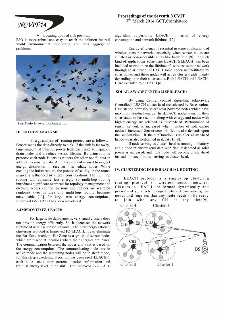
Fig 1 Proposed Architecture
In figure1, it shows the proposed system architecture and itsvarious components. The system architecture has four agentsthey are Aggregator Agent, Patient Agent, Doctor Agent and
Nurse Agent. A group of patients has been connected to thecluster head which act as Patient Agent. Different cluster headis used to send the information to the Access point which isused to access the patient information. The Patient agent issituated at the cluster head of the network and the information
has been transferred to the base station where AggregatorAgent presents. The Aggregator Agent is used to receive theinformation and checks for denotations of anomalous readingswhich is sent by the Patient Agent and start alerting to DoctorAgent and Nurse Agent. Then the Aggregator Agent transmitsthe patient’s parameters to the Cloud computing for
destination processing and storing in the database. TheDoctor Agent sand Nurse Agent are situated on the
mobile handheld device and send the information for the onduty Doctor and nurse and also to the patient’s assigned
doctor who may not be on duty. The Doctor Agent and NurseAgent offer alerts to the medical agents and allow thequerying of patient’s information which includes current and
past sensor readings .The proposed system will be extended tosupport mobile or remote patients and using Patient Agentswhich is situated on mobile handheld devices capable ofreceiving and transmitting readings for the sensors observingthe patient’s physiological information. By using cloud
computing, the information from the Patient information has been stored in the cloud storage device. The Proposed systemcan be considered as a Medical Internet of Things which is
possible to observe, track and uniquely identify all theseinformation which is connected to the system via the Internet.
V SIMULATION SCENARIOS:
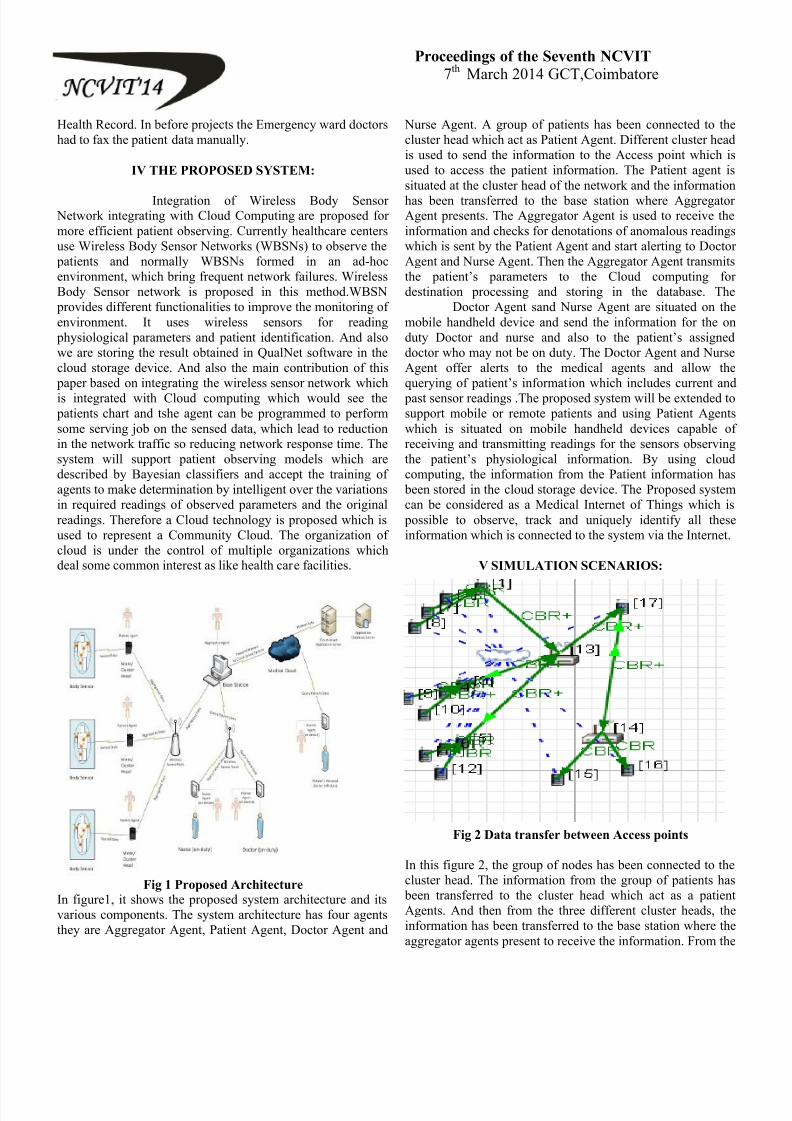
Fig 2 Data transfer between Access points
In this figure 2, the group of nodes has been connected to thecluster head. The information from the group of patients has
been transferred to the cluster head which act as a patientAgents. And then from the three different cluster heads, theinformation has been transferred to the base station where theaggregator agents present to receive the information. From the

8/12/2019 various papers in our college
http://slidepdf.com/reader/full/various-papers-in-our-college 20/69
Proceedings of the Seventh NCVIT7th March 2014 GCT,Coimbatore
Aggregator Agent, the information has been transferred to thedoctor agent and nurse agent through another Access Point.The information has been transferred from one access point tothe other access point and then it transfer to the particularagent which belongs to the information of the patient.
Fig 3 Data transfer between access point and cluster head
In this figure 3, Data transfer from one cluster head to other. Itmeans the group of patient’s information has been transferred
from one agent to other agent. Then the agent sends theinformation to the access point which is used to access theinformation of the patient and send to the base station. Fromthe base station, the data has been transferred to anotheraccess point which the information is then passed to the nurseagent and doctor agent.
VI. SIMULATION RESULTS
Fig 4: Average throughput
Throughput means sum of data rates that are delivered to allterminals in a network. Average rate of successful message
delivery. It passes through certain network node. Measured in bits/second. Graph shows the information which is received atthe receiver. Node 1, 3 and 5 are cluster heads which receivesinformation from the patients. And the information received isshown in above graph.
Fig 5: Average Delay
In this figure 6, the average delay shows the informationtransferring delay time in the simulation process. Delay varieson each and every node due to the variation of packet size.And it only occurs between 0 to 3.5. Nodes 1, 3 and 5 arecluster heads in which delay occurs. Delays occur in thecluster heads which is also called as a patient Agent. Metric
value of different nodes is used to determine the best possibleroute which has low metric value.
Fig 6: Received informationReceived information such as delay, throughput and jittervalue from the three different cluster heads is received. Thenode 1,3 and 5 are cluster heads which sends the informationto the access point of node 14.Metric value is to determine the
best possible route which has low metric value.CLOUD STORAGE SIMULATION
Fig 7: Simulation of Net beans software
In this Net beans software, the java coding is applied for thecloud storage. In the front end process, Java software is usedand in the back end, SQL server is used to store the data. The
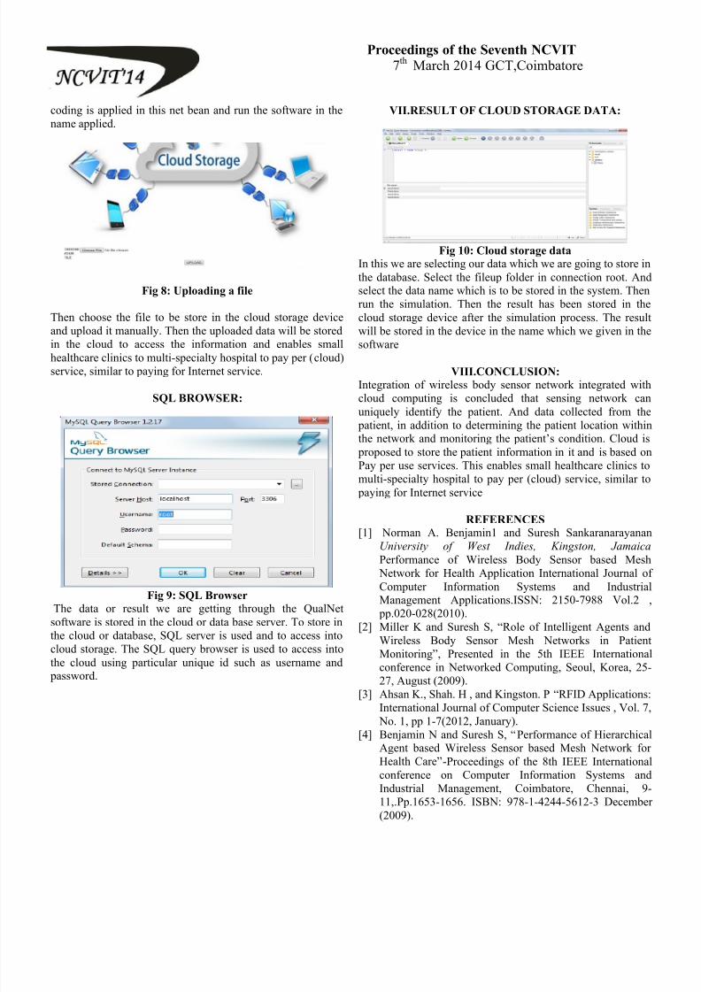
8/12/2019 various papers in our college
http://slidepdf.com/reader/full/various-papers-in-our-college 21/69
Proceedings of the Seventh NCVIT7th March 2014 GCT,Coimbatore
coding is applied in this net bean and run the software in thename applied.
Fig 8: Uploading a file
Then choose the file to be store in the cloud storage deviceand upload it manually. Then the uploaded data will be stored
in the cloud to access the information and enables smallhealthcare clinics to multi-specialty hospital to pay per (cloud)service, similar to paying for Internet service.
SQL BROWSER:
Fig 9: SQL Browser
The data or result we are getting through the QualNetsoftware is stored in the cloud or data base server. To store inthe cloud or database, SQL server is used and to access intocloud storage. The SQL query browser is used to access intothe cloud using particular unique id such as username and
password.
VII.RESULT OF CLOUD STORAGE DATA:
Fig 10: Cloud storage data
In this we are selecting our data which we are going to store inthe database. Select the fileup folder in connection root. Andselect the data name which is to be stored in the system. Thenrun the simulation. Then the result has been stored in thecloud storage device after the simulation process. The resultwill be stored in the device in the name which we given in the
software
VIII.CONCLUSION:
Integration of wireless body sensor network integrated withcloud computing is concluded that sensing network canuniquely identify the patient. And data collected from the
patient, in addition to determining the patient location withinthe network and monitoring the patient’s condition. Cloud is
proposed to store the patient information in it and is based onPay per use services. This enables small healthcare clinics tomulti-specialty hospital to pay per (cloud) service, similar to
paying for Internet service
REFERENCES[1] Norman A. Benjamin1 and Suresh Sankaranarayanan
University of West Indies, Kingston, Jamaica
Performance of Wireless Body Sensor based Mesh Network for Health Application International Journal ofComputer Information Systems and IndustrialManagement Applications.ISSN: 2150-7988 Vol.2 ,
pp.020-028(2010).[2] Miller K and Suresh S, ―Role of Intelligent Agents and
Wireless Body Sensor Mesh Networks in PatientMonitoring‖, Presented in the 5th IEEE Internationalconference in Networked Computing, Seoul, Korea, 25-27, August (2009).
[3] Ahsan K., Shah. H , and Kingston. P ―RFID Applications:International Journal of Computer Science Issues , Vol. 7,
No. 1, pp 1-7(2012, January).[4] Benjamin N and Suresh S, ―Performance of Hierarchical
Agent based Wireless Sensor based Mesh Network forHealth Care‖-Proceedings of the 8th IEEE Internationalconference on Computer Information Systems andIndustrial Management, Coimbatore, Chennai, 9-11,.Pp.1653-1656. ISBN: 978-1-4244-5612-3 December(2009).

8/12/2019 various papers in our college
http://slidepdf.com/reader/full/various-papers-in-our-college 22/69
Proceedings of the Seventh NCVIT7th March 2014 GCT,Coimbatore
[5] Benjamin, N. A., ―Performance of Wireless Body Sensor
based Mesh Network for Health Application‖,
International Journal of Computer Information Systemsand Industrial Management Applications, pp 21-28(2009).
[6] Barnes D et al, ―Performance analysis of Client/serverversus Agent based communication in Wireless Sensor
Networks for health applications‖, Proceedings of 2009
IEEE Electro Information Technology (EIT 09), Windsor,Canada, June 7-9, pp.271-276. ISBN: 978-1-4244-3355-1(2009).
[7] Bui. N., Castellani, P., Rossi, M.,., Zorzi, M. & Shelby M―Architecture and protocols for the internet of things: A
case study‖. Proceedings of IEEE International
Conference on Pervasive Computing andCommunications Workshops, pp. 678-683(2010).
[8] Sank aranarayanan & Edwards T. ―Applications of
Intelligent Agents in Hospital Search and AppointmentSystem‖. International Journal of E-Services and MobileApplications, Vol. 3, No. 4, pp 57-81.(2011).
[9] Shah M.A, Swaminathan R, and Baker M, ―Privacy
preserving audit and extraction of digital contents,‖
Cryptology ePrint ,Report 2008/9186, (2008).[10] Fifah, B S. ―NFC Enabled Patient appointment System‖,
Bachelor of Internet Computing Project, Department ofComputing and Information Systems,(2013)
[11] Korkmaz. I., Atay, C., and Kyparisis.G (2010). ―A
Mobile Patient Monitoring System Using RFID‖.
Latest Trends on Computers, Vol. 3, pp 726-732.[12] G. Ateniese, S. Kamara, and J. Katz, ―Proofs of
storage from homomorphic identification protocols,‖
in Asiacrypt ,pp. 319 – 333(2009).[13] Kailing .R, Rantzau. S, K. Beier and Grandison, T., ,
(2006). Discovery Services Enabling RFIDTraceability in EPC global Networks. Proceedings ofthe 13th International Conference on Management ofData 2006, Delhi, India. December 2006 .
[14] Mitrokotsa. A, and Douligeris, C ―Integrate RFID
and Sensor Networks: Architectures andApplications‖, pp 511-536. (2009).
[15] Lefebvr.E, Castro. L., and Lefebvre, L. A..―Assessing the prevailing implementation issues of
RFID in healthcare: A five-phase implementationmodel‖. International Journal of Computers and
Communications, Vol. 5, No. 2, pp 101-117(2011).[16] Morak, J., Schreier, G. ―MHealth based on NFC
Technology-Preliminary results from Medium ScaleProof of Concept Projects‖, Proceedings of Ehealth ,
Austria, (2012).
8/12/2019 various papers in our college
http://slidepdf.com/reader/full/various-papers-in-our-college 23/69
Proceedings of the Seventh NCVIT
7th March 2014 GCT,Coimbatore
INCREASE THE EFFICIENCY IN WIRELESS SENSOR
NETWORK USING MOBI-CLUSTER ALGORITHM
Sridhar.S. , Vidya.A.R.
Department of Computer science and Engineering Regional centre, Anna [email protected] , [email protected]
Abstract: A wireless sensor network consists of
spatially distributed autonomous sensors to
monitor physical or environmental conditions and
to cooperatively pass their data through the
network to a main location. Utilizing Mobi-
clustering algorithms to form a hierarchical
network topology is a common method of
implementing network management and data
aggregation in wireless sensor networks. Mobi-
clustering algorithm is used minimizing theoverall network overhead and energy. Power
consumption and maximizing the life time are the
important aspects of wireless sensor networks.
The proposed protocol aims at minimizing the
overall network overhead and energy Distribution
associated with the multi-hop data retrieval
process while also ensuring balanced energy
consumption among Sensor Nodes and extended
network lifetime. Arranging cluster sizes and
transmission ranges (ACT), reduces the size of
clusters near the base station and provides energy
consumption. But it does not concentrate on
coverage problem and maximizing the life time. In
this project is developed similar to, the Integer
Linear Programming (ILP) problem that
formulates the coverage problem and maximizes
life network time of the sensor nodes. It
implement the optimization problem, with the
objective function and several constraints of this
problem can be solved to optimality by using
CPLEX solver.
I ndex Terms: Cluster, Energy consumption,Energy-Balancing, Routing protocol, Wirelesssensor networks.
I. INTRODUCTION
A. Overview Of Wi reless Sensor Networks
Wireless Sensor Networks have emerged asresearch areas with an overwhelming effect on practical application development. They permit finegrain observation of the ambient environment at aneconomical cost much lower than currently possible.
In hostile environments where human participationmay be too dangerous in sensor network which may provide a robust service. Sensor networks aredesigned to transmit data from an array of sensornodes to a data repository on a server. WSN has
potential to design many new applications forhandling emergency, military and disaster reliefoperations that requires real time information forefficient coordination and planning. Sensors are
devices that produce a measurable response to achange in a physical condition like temperature,humidity, pressure etc.
WSNs may consist of many different types of sensorsuch as seismic, magnetic, thermal, visual, infrared,and acoustic and radar capable to monitor a widevariety of ambient conditions. Through eachindividual sensor may have severe resource constraintin terms of energy, memory, communication andcomputation capabilities; large number of them maycollectively monitor the physical world and processthe information on the fly environment. In a WSN,sensor nodes monitor the environment, detect events
of interest, produce data and collaborate inforwarding the data towards a sink, which could be agateway, base station, storage node, or querying user.A sensor network is often deployed in an unattendedand hostile environment to perform the monitoringand data collection tasks. When it is deployed in suchan environment, it lacks physical protection and issubject to node compromise. After compromising oneor multiple sensor nodes, an adversary may launchvarious attacks to disrupt the in-networkcommunication.
B. Wi reless Sensor Networks Characteri stics
A WSN is different from other popularwireless networks like cellular network, WLAN andBluetooth in many ways. Compared to other wirelessnetworks, a WSN has much more nodes in a network,distance between the neighboring nodes is muchshorter and application data rate is much lower also.

8/12/2019 various papers in our college
http://slidepdf.com/reader/full/various-papers-in-our-college 24/69
Proceedings of the Seventh NCVIT
7th March 2014 GCT,Coimbatore Due to these characteristics, power consumption in asensor network will be minimized. To keep the costof the entire sensor network down, cost of eachsensor needs to be reduced. It is also important to usetiny sensor nodes. A smaller size makes it easier for a
sensor to be embedded in the environment it is in.WSNs may also have a lot of redundant data sincemultiple sensors can sense similar information. Thesensed data therefore need to be aggregated todecrease the number of transmission in the network,reducing bandwidth usage and eliminatingunnecessary energy consumption in both transmissionand reception.
The main characteristics of a WSN include,
Power consumption using batteriesor energy harvesting
Ability to cope with node failure Mobility of nodes Heterogeneity of nodes Scalability to large scale deployment Ease of use
C. Benefi ts Of Wi reless Sensor Network
The two primary motivations for choosing awireless network over a wired approach are theflexibility and the cost-savings associated witheliminating cables and wires.
Flexibility Low cost Lifetime maximization
D. Overview Of Clusteri ngThe large-scale deployment of wireless
sensor networks (WSNs) and the need for dataaggregation necessitate efficient organization of thenetwork topology for the purpose of balancing theload and prolonging the network lifetime. Clusteringhas proven to be an effective approach for organizingthe network into a connected hierarchy. In this article,we highlight the challenges of clustering in a WSN,discuss the design rationale of the different clusteringapproaches, and classify the proposed approaches based on their objectives and design principles. Wefurther discuss several key issues that affect the practical deployment of clustering techniques insensor network applications. In order to support dataaggregation through efficient network organization,
nodes can be partitioned into a number
of small groups called clusters. Each cluster has acoordinator, referred to as a cluster head, and anumber of member nodes.
Clustering results in a two-tier hierarchy inwhich cluster heads (CHs) form the higher tier whilemember nodes form the lower tier. The membernodes report their data to the respective CHs.Research on clustering in WSNs has focused ondeveloping centralized and distributed algorithms tocompute connected dominating sets. The CHsaggregate the data and send them to the central basethrough other CHs. Because CHs often transmit dataover longer distances, they lose more energycompared to member nodes. The network may beclustered periodically in order to select energy-abundant nodes to serve as CHs, thus distributing the
load uniformly on all the nodes. Besides achievingenergy efficiency, clustering reduces channelcontention and packet collisions, resulting in betternetwork throughput under high load.
E. Cluster Network Characteri stics
A basic cluster has the followingcharacteristics:
Multiple computing nodes Low cost
A fully functioning computer with its
own memory, CPU, possibly storage Own instance of operating system
Computing nodes are connected byinterconnects
Typically low cost, high bandwidthand low latency
Permanent, high performance datastorage
A resource manager to distribute andschedule jobs
The middleware that allows thecomputers act as a distributed or parallel system
Parallel applications designed to runon it
F. Benefi ts Of ClustersBenefits and reasons for popularity of
clusters can be listed as follows: No expensive and long development

8/12/2019 various papers in our college
http://slidepdf.com/reader/full/various-papers-in-our-college 25/69
Proceedings of the Seventh NCVIT
7th March 2014 GCT,Coimbatore projects. Building clusters is easy, compared to building a dedicatedsupercomputer.
Price performance benefit: Highly available COTS products are used.
Flexibility of configuration: Number of nodes, nodes‟ performance, andinter-connection topology can beupgraded. System can be modifiedwithout loss of prior work. Two typesof scaling can be defined.
Scale up: Increasing the throughput of each computing node.
Scale out: Increase the number of computing nodes. Requires efficientI/O between nodes and cost effectivemanagement of large number ofnodes.
II. RELATED WORK
Wireless distributed micro sensor systemswill enable the reliable monitoring of a variety ofenvironments for both civil and military applications.In this paper, we look at communication protocols,which can have significant impact on the overallenergy dissipation of these networks [2]. Based onour findings that the conventional protocols of directtransmission, minimum-transmission-energy, multi-hop routing, and static clustering may not be optimalfor sensor networks, we propose LEACH (Low-Energy Adaptive Clustering Hierarchy), a clustering- based protocol that utilizes randomized rotation oflocal cluster base stations (cluster-heads) to evenlydistribute the energy load among the sensors in thenetwork. LEACH uses localized coordination toenable scalability and robustness for dynamicnetworks, and incorporates data fusion into therouting protocol to reduce the amount of informationthat must be transmitted to the base station.Simulations show that LEACH can achieve as muchas a factor of 8 reduction in energy dissipationcompared with conventional routing protocols. Inaddition, LEACH is able to distribute energydissipation evenly throughout the sensors, doublingthe useful system lifetime for the networks we
simulated.
Wireless sensor networks (WSNs) arecomposed of a large number of inexpensive power-constrained wireless sensor nodes, which detect andmonitor physical parameters around them throughself-organization. Utilizing clustering algorithms toform a hierarchical network topology is a commonmethod of implementing network management anddata aggregation in WSNs [3]. Assuming that the
residual energy of nodes follows the randomdistribution, we propose a load-balanced clusteringalgorithm for WSNs on the basis of their distanceand density distribution, making it essentiallydifferent from the previous clustering algorithms.
Simulated tests indicate that the new algorithm can build more balanceable clustering structure andenhance the network life cycle. A new method is proposed in this paper to improve Low EnergyAdaptive Clustering Hierarchy(LEACH) by electingcluster heads according to the residual energy of thenodes dynamically[4].
A sliding window is set up to adjust theelecting probability and keep stable the expectednumber of the cluster heads using two parameters inthis method, one is the initial energy information ofthe nodes and the other is the average energyinformation of those that have not already beencluster heads in the network. Meanwhile, the numberof cluster heads which is fixed in the entire networklifetime in LEACH is modified to be a variableaccording to the number of the living nodes.Simulations show that the improvement for First Node Dies (FND) and Half of the Nodes Alive(HNA) is 41% and 36%, respectively over LEACH,17% and 26% for Low Energy Adaptive ClusteringHierarchy with Deterministic Cluster-Head Selection(LEACH-DCHS), 22% and 21% for Advanced LowEnergy Adaptive Clustering Hierarchy (ALEACH).
Networking together hundreds or thousands
of cheap micro-sensor nodes allows users toaccurately monitor a remote environment byintelligently combining the data from the individualnodes. These networks require robust wirelesscommunication protocols that are energy efficientand provide low latency [5]. In this paper, theydeveloped and analyze low-energy adaptiveclustering hierarchy(LEACH), a protocol architecturefor micro-sensor networks that combines the ideas ofenergy-efficient cluster-based routing and mediaaccess together with application-specific dataaggregation to achieve good performance in terms ofsystem lifetime, latency, and application-perceived
quality. LEACH includes a new, distributed clusterformation technique that enables self-organization oflarge numbers of nodes, algorithms for adaptingclusters and rotating cluster head positions to evenlydistribute the energy load among all the nodes, andtechniques to enable distributed signal processing tosave communication resources. Our results show thatLEACH can improve system lifetime by an order ofmagnitude compared with general-purpose multi-hopapproaches.

8/12/2019 various papers in our college
http://slidepdf.com/reader/full/various-papers-in-our-college 26/69
Proceedings of the Seventh NCVIT
7th March 2014 GCT,Coimbatore
III. PROPOSED WORK
In a WSN, the sensor network is often
deployed in an unattended and hostile environment to perform data collection tasks. It lacks of physical protection and is subject to node compromise when itis deployed in such an environment. An importantobjective of any clustering technique is networkconnectivity. For intra-cluster communication, acluster member communicates with its CH eitherdirectly. Connectivity in this case is a result of thesuccess of cluster formation. Network density has to be sufficiently high in order to ensure that enoughgateways are present at the intersection areas betweenclusters. After compromising one or multiple sensornodes, an challenger may launch various attacks todisrupt the in-network communication. compromised
nodes drop or modify the packets that they aresupposed to forward.
Utilizing Mobi-clustering algorithms to forma hierarchical network topology is a common methodof implementing network management and dataaggregation in wireless sensor networks. Powerconsumption and maximizing the life time are theimportant aspects of wireless sensor networks. The proposed protocol aims at minimizing the overallnetwork overhead and energy Distribution associatedwith the multi-hop data retrieval process while alsoensuring balanced energy consumption among Sensor
Nodes and extended network lifetime. Arrangingcluster sizes and transmission ranges (ACT), reducesthe size of clusters near the base station and providesenergy consumption. But it does not concentrate oncoverage problem and maximizing the life time. ACTconsists of the cluster formation phase, dataforwarding phase and cluster maintenance phase. Thefollowing conditions are assumed
The positions of BS and sensor nodes arefixed.
The power of all sensor nodes is the same inthe beginning.
Each sensor node transmits one unit of datato the CH in each round.
A CH aggregates data and then forwardsthem to BS.
Sensor nodes are uniformly distributed in thesensor field with density dn.
Sensor nodes can adjust power levels. Themaximum power level can be used intransmitting data to BS directly.
The covered area is a W×L rectangle, where
W is the width and L is the length. Note thatthe area considered in LEACH and BCDCP
are also rectangular.
The proposed work consist of the list of moduleswhich describes the network life time and coverage
area in wsn.
Node Creation. Cluster head selection. Cluster building phase. Cluster maintenance phase.
A. Node Creation
In this module, wireless sensor nodes arecreated and information collected from the sensornodes. Various information from the sensor nodes
collected though multi hop communication. Calculatethe distance from base station to each sensor nodeand individual node to node distance also calculateusing the cluster radius .According to the radioenergy dissipation model [4], the energy consumed by sensor nodes for transmitting k bits of data at adistance d is:
(,) =− () +− (,), That is ,
(,) =××××2 (1)
is the energy used in a sensor node for a
transmitting one bit of message. is the energyconsumed by the transceiver during its transmission
of one bit data through amplifier.
Eq. (1) is simplified into eq. (2):
(,) =×(+)×2 (2)
Eq. (2 to calculate the radius of the each cluster.
Fig.1. Level structure

8/12/2019 various papers in our college
http://slidepdf.com/reader/full/various-papers-in-our-college 27/69
Proceedings of the Seventh NCVIT
7th March 2014 GCT,Coimbatore
B. Cluster H ead Selection
Cluster head is selected by comparing theremaining power of the nodes. This approach helps to prolong the lifetime of the nodes. If the power ofsensor node is higher than other sensor nodes in agroup that will be selected as a cluster head. DSBCAfollows a distributed approach to establishhierarchical structure in self-organizing mode withoutcentral control. DSBCA selects the random nodes totrigger clustering process first. Then the trigger nodecalculates its connected density and distance from the base station to determine cluster radius and becamethe temporary cluster head selection.
C. Cluster Bui lding Phase
DSBCA sets the threshold of cluster size.The number of cluster nodes cannot exceed thethreshold to avoid forming large clusters, which willcause extra overhead and thus reduce networklifetime. When the cluster head node receives Joinmessage sent by the ordinary node, it will comparethe size of cluster with threshold to accept newmember and update the count of cluster nodes if thesize is smaller than threshold, or reject the request. Ifthe rejected node has cluster head already, theclustering process cases. Otherwise, it finds anothersuitable cluster to join. Each member node of cluster
maintains a cluster information table, which saves theHID, HD, SID and other information.
If a node receives transmitting packet inwork, it will update its cluster information table inthat order. For example, the node checks HD in anewly received packet, if HD is smaller, then itupdates the value of HD in table, with SID updated.That is to say, it has found a shorter path to clusterhead and sets the new SID as its forwarding node.There is only a single HID entry in the ordinary node because it belongs to one cluster head, but theoverlapping cluster node has multiple HID
information entries for different clusters. DSBCAalgorithm avoids the fixed cluster headscheme(cluster head manages cluster and forwardsdata, so it consumes energy faster than other nodes),with periodic substitution to balance the node energyutilization.
Data forwarding :
The data forwarding phase consists of intra-
cluster data forwarding and inter-cluster dataforwarding.,
Intra-cluster data forwarding:
After cluster setup, CHs collect
data transmitted from cluster members and perform data aggregation. If a CH adoptssingle-hop for intra-cluster data forwarding,the sensor nodes farthest from the CHconsume much more energy in largerclusters. To avoid this, we employ theconcept of the MST to reduce the distance between the sensor nodes and CHs for datatransmission.
In a network with a high density ofsensor nodes, the transmitted informationmay go far before reaching the targeted CHsif the MST is applied. Therefore, we assign
a hop count H. At the time the datatransmission begins, the data forwardingfrom one sensor node to another causes thevalue of H to be decreased by one. Whenthe value H is equal to zero but the data failsto reach the targeted CH, the sensor nodethat holds the data at the moment passes thedata to the CH directly to avoid time-consuming routing.
Inter-cluster data forwarding:
The inter-cluster data forwardingrefers to transmissions of CHs‟ collecteddata from cluster members in the ith level to
the next CH in the (i-1)th level closest to theBS until the transmitted data reach the BS.
D. Cluster Maintenance Phase
The power of a CH may be exhausted aftergoing through cluster setup and several datatransmissions. At this time cluster maintenance, suchas picking out a new CH and merging clusters,should be performed to continue data transmissionsfrom sensor nodes to the BS. Cluster maintenance isalso required when a CH is away from its original
cluster due to the mobility of sensor nodes. In thetraditional cluster-based routing protocol, the clustermaintenance phase is very important because theloads imposed on the CHs are much larger than thoseimposed on the sensor nodes; as a result, the power ofCHs may be exhausted quickly. In case the power ofthe CH approaches depletion, a new CH is elected. InACT, the cluster maintenance phase consists of CHrotations within a cluster and cross-level datatransmission to the BS.

8/12/2019 various papers in our college
http://slidepdf.com/reader/full/various-papers-in-our-college 28/69
Proceedings of the Seventh NCVIT
7th March 2014 GCT,Coimbatore
CH rotations in a cluster:
Define the threshold of CH poweras T (15% of initial energy). When theremaining power of a CH is under T, a new
CH is selected from among the sensornodes, usually the one closest to the CHwithin its cluster group, while a change msgis broadcast to inform cluster members ofthe change of CH.
Cross-level data transmission to BS:
In ACT, clusters in the 1st level arethe smallest in size, and thus, fewer clustermembers are found in the 1st level. If thesensor nodes within a cluster take turnsserving as CHs, the process may finishquickly as there are not enough sensornodes. When the BS is aware that each
sensor node in the 1st level can no longerserve as a CH, it broadcasts a message toallow the CHs in the 2nd level to transmitdata to BS directly.
Let the network topology bedivided into K levels with the CHs in the 1stlevel transmitting data to BS. When the power of each sensor node in the 1 st level isexhausted after a while, the CHs in the 2ndlevel assume the process of datatransmission (the same for 3rd level, 4thlevel,…Kth level). In this way, the networklifetime can be extended.
Cluster head selection, cluster setup andintra-cluster communications are the fundamentalmethods of forming a cluster. Moreover, while ACTdoes consider ―cross-level data transmission to BS‖
and ―communication load balance for each cluster ‖LEACH, BCDCP and MRLEACH do not.
IV. SIMULATION RESULTS AND
PERFORMANCE ANALYSIS
We conduct simulations to study the performanceof the proposed ACT and the other three schemes,LEACH, BCDCP and MR-LEACH.
A. Simulati on setup
We use a combination of the NS-2 [6] and theMannasim [7] in simulations.We apply the first orderradio model [5] to evaluate the energy dissipation insensor nodes. We average the results based on 300runs for each scenario. In addition, we are interestedin the following performance metrics: (1) average
energy dissipation; (2) standard deviation of energyconsumption of CHs (utilizing standard deviation toobserve the scattering of values); (3) the number ofsensors alive; and (4) network lifetime (which isdefined as the number of rounds in which the first
sensor node uses up its energy).
B. Simu lation results
The average energy dissipation in sensornodes in four types of routing protocols, namelyLEACH, BCDCP, MRLEACH and ACT, within arange of 80 _ 120 m2. The energy dissipationfound in LEACH is greater than that in BCDCP,MRLEACH and ACT as a whole. This is becauseLEACH adopts single-hop communications withthe CH sending its data directly to the BS;BCDCP, MR-LEACH and ACT utilize multi-hopcommunications that require less energy
consumption from each sensor node.
Fig.2. Network lifetime of different nodedensities
The network lifetime for different nodedensities of 40, 60, 80, 100 and 120 nodes. Wedefine network lifetime as the number of rounds
before the first sensor node uses up its energy inthe network.
Table.1. The simulation parameters
PARAMETER VALUE
Network size 80× 120 2
Base station location (0,40)m

8/12/2019 various papers in our college
http://slidepdf.com/reader/full/various-papers-in-our-college 29/69
Proceedings of the Seventh NCVIT
7th March 2014 GCT,Coimbatore Number of sensor nodes 96 nodes
Density 1 node/ 100 2
Initial energy of each 0.5Jsensor node
Data packet size 500 bytes
50 nJ/bit
100 pJ/bit/ 2
K 3 for ACT ,4 for MR-LEACH
V. CONCLUSION
Mobi-clustering algorithm can form morestable and reasonable clusters, and also improve thenetwork life cycle. Wireless sensor network requiressensor node to work for a long period of time without
human intervention. Using Integer LinearProgramming(ILP) problem to avoids the coverage problem and increases the network lifetime, thatcannot be achieved in existing system. The clustersformed by DSBCA is based on the distance from basestation, distribution of nodes and residual energyaccord with actual network. Hence, it achieves a better performance even when the number of nodeschanges As a result, the energy consumptiondecreases effectively. The cluster structure changes ineach round in LEACH, but DSBCA maintainsrelatively stable clustering structure in whichswitching of cluster head often occurs in the same
cluster.
REFERENCES
[1]. Wei Kuang Lai, Chung Shuo Fan, Lin Yan Lin,sep 2011, ―Arranging cluster sizes and
transmission ranges for wireless sensornetworks‖, Elsevier, Taiwan, 183(2012) 117-131.
[2]. W.R. Heinzelman, A. Chandrakasan, H.Balakrishnan, January 2000,‖ Energy-efficientcommunication protocol for wireless microsensornetworks‖, Proceedings of Hawaii InternationalConference on System Sciences (HICSS), Hawii,
pp. 1 – 10.
[3]. Ying Liao, Huan Qi, and Weiqun Li, MAY2013,‖Load-Balanced Clustering Algorithm WithDistributed SelfOrganization for Wireless Sensor Networks‖,
IEEESensors Journal, VOL. 13, NO. 5.
[4]. Aimin Wang, Dailiang Yang, Dayang Sun ,Dec2011,‖Clustering Algorithm Based On EnergyInformation And Cluster Heads ExpectationFor Wireless Sensor Networks‖, Computers and Electrical
Engineering 38(2012) 662 – 671.
[5]. W.R. Heinzelman, A. Chandrakasan, H.Balakrishnan, Oct 2002, ― An application-specific protocol architecture forwireless microsensor networks‖, IEEE
Transactions onWireless Communications 1 (2002) 660 – 670.
[6]. Network simulator, NS-2.<http://www.isi.edu/nsnam/ns/>.
[7]. Mannasim.
<http://www.mannasim.dcc.ufmg.br/index.htm>.

8/12/2019 various papers in our college
http://slidepdf.com/reader/full/various-papers-in-our-college 30/69
Proceedings of the Seventh NCVIT
7th March 2014 GCT,Coimbatore
DESIGN OF A HYBRID WIRELESS NETWORK USING
ENHANCED QUALITY OF SERVICE ORIENTED
DISTRIBUTED ROUTING PROTOCOL
T.Murugeswari, M. Aswathy Department of Applied electronics, Hindustan college of engineering and technology, Coimbatore
Abstract
As wireless communications gains popularity,significant research has been devoted to supportingreal time transmission with stringent quality ofservice requirements for wireless applications. At thesame time, a wireless hybrid network that integrates amobile wireless adhoc network and a wirelessinfrastructure network has been proven to be a betteralternative for the next generation wireless network.
Quality of service Oriented Distributed routing protocol enhance the Quality of Service capability ofhybrid networks. In this paper improve the quality ofQuality of service Oriented Distributed routing protocol and develop a protocol Enhanced Quality ofservice Oriented Distributed routing protocol. TheEnhanced Quality Of service Oriented Distributedrouting protocol is mobility resilient than Quality ofservice Oriented Distributed routing protocol. TheEnhanced Quality of service Oriented Distributedrouting protocol improves the throughput anddecreased the overhead. Hence this model shows thatEnhanced Quality of service Oriented Distributed
routing protocol can provide high Quality of Service performance in terms of overhead, transmission delayand mobility resilient. This also increase the energyefficiency of Quality of service Oriented Distributedrouting protocol and avoid the energy harvesting problem by using Enhanced Quality of serviceOriented Distributed routing protocol. Hence it leadsto develop a high efficiency hybrid network usingEnhanced Quality of service Oriented Distributedrouting protocol.
Key Words: Infrastructure Wireless Network,
Adhoc Mode Network, Hybrid Wireless Network,
Quality of Service Distributed oriented Routing
Protocol.
I. INTRODUCTION
Nowadays, people wish to watch videos, playgames, watch TV and make long-distanceconferencing via wireless mobile devices. Theemergence and the envisioned future of real-time and
multimedia applications have stimulated the need ofhigh Quality of Service (QoS) support in wireless andmobile networking environments [1]. The QoS
support reduces end-to-end transmission delay andenhances throughput to guarantee the seamlesscommunication between mobile devices and wirelessinfrastructures. In concert hybrid wireless networks(i.e., multi-hop cellular networks) have been provento be a better network structure for the next
generation wireless networks [2 – 5], and can help todeal with the inflexible end-to-end QoS requirementsof different applications. Hybrid networkssynergistically combine infrastructure networks andMANETs to leverage each other. Specifically,infrastructure networks improve the scalability ofMANETs, while MANETs automatically establishself organizing networks, extending the coverage ofthe infrastructure networks. Hybrid wireless networkhave the characteristics of high mobility andfluctuating bandwidth. So guarantying the QoS stillremains an open question.
II. EXISTING SYSTEM
As wireless communication gains popularity,significant research has been devoted to supportingreal-time transmission with for wireless applications.At the same time, a wireless hybrid network thatintegrates a mobile wireless ad hoc network(MANET) and a wireless infrastructure network has been stringent Quality of Service (QoS) requirements proven to be a better alternative for the nextgeneration wireless networks. By directly adoptingresource reservation-based QoS routing forMANETs, hybrids networks inherit invalidreservation and race condition problems in MANETs.How to guarantee the QoS in hybrid networksremains an open problem. In this paper, we propose aQoS-Oriented Distributed routing protocol (QOD) toenhance the QoS support capability of hybridnetworks. Taking advantage of fewer transmissionhops and any cast transmission features of the hybridnetworks, QOD transforms the packet routing problem to a resource scheduling problem. QODincorporates five algorithms: (1) a QoS-guaranteed

8/12/2019 various papers in our college
http://slidepdf.com/reader/full/various-papers-in-our-college 31/69
Proceedings of the Seventh NCVIT
7th March 2014 GCT,Coimbatore neighbor selection algorithm to meet the transmissiondelay requirement, (2) a distributed packet schedulingalgorithm to further reduce transmission delay,(3) amobility-based segment resizing algorithm thatadaptively adjusts segment size according to node
mobility in order to reduce transmission time, (4) atraffic redundant elimination algorithm to increasethe transmission throughput, and (5) a dataredundancy elimination based transmission algorithmto eliminate the redundant data to further improve thetransmission QoS. Analytical and simulation results based on the random way-point model and the realhuman mobility model show that QOD can providehigh QoS performance in terms of overhead,transmission delay, mobility resilience andscalability.
III. PROPOSED SYSTEM
As wireless communications gains popularity,significant research has been devoted to supportingreal time transmission with stringent quality ofservice requirements for wireless applications. At thesame time, a wireless hybrid network that integrates amobile wireless adhoc network and a wirelessinfrastructure network has been proven to be a betteralternative for the next generation wireless network.Quality of service Oriented Distributed routing protocol enhance the Quality of Service capability ofhybrid networks. In this paper improve the quality ofQuality of service Oriented Distributed routing protocol and develop a protocol Enhanced Quality ofservice Oriented Distributed routing protocol. TheEnhanced Quality Of service Oriented Distributedrouting protocol is mobility resilient than Quality ofservice Oriented Distributed routing protocol. TheEnhanced Quality of service Oriented Distributedrouting protocol improves the throughput anddecreased the overhead. Hence this model shows thatEnhanced Quality of service Oriented Distributedrouting protocol can provide high Quality of Service performance in terms of overhead, transmission delayand mobility resilient. This also increase the energyefficiency of Quality of service Oriented Distributedrouting protocol and avoid the energy harvesting
problem by using Enhanced Quality of serviceOriented Distributed routing protocol. Hence it leadsto develop a high efficiency hybrid network usingEnhanced Quality of service Oriented Distributedrouting protocol.
3.1 Hybrid Wireless Network
A wireless hybrid network that integrates amobile wireless ad hoc network (MANET) and a
wireless infrastructure network. Multi-hop cellularnetworks (also called hybrid networks) appear to be a promising combination of the dynamics of mobile adhoc networks and the reliability of infrastructure
wireless networks. These hybrid networks off ers
several advantages for users as well as operators. Thenetwork topology can be dynamically adapted to therespective needs reducing installation costs for the provider, the overall coverage area can be extendedand nodes can reduce their energy consumption fortransmitting packets due to shorter distances.However, several weaknesses known from mobile adhoc networks persist. In the context of hybridnetworks new possibilities to deal with theseweaknesses become available. Besides the securityand routing issues the cooperation among nodes is ofgreat importance.
3.2 Introduction To Manet
Hybrid network is the integration of Manet andwireless infrastructure network. This is the bestalternative for next generation network. Ad-hocnetworks are mobile networks that operate in theabsence of any fixed infrastructure, employing peer-to-peer communication to establish networkconnectivity. These networks have a wide range ofapplications such as disaster relief and fieldoperations, war front activities, and communication between automobiles activities and it is a self startingdynamic network comprising of mobile nodes, whereeach and every participation node voluntarily
transmit the packets destined to some remote nodeusing wireless (radio signal) transmission. An ad hocnetwork doesn’t have any centralized arbitrator orserver. In MANET each and every mobile node isassumed to be moving with more or less relativespeed in arbitrary direction. Because of that there isno long term guaranteed path from any one node toother node. MANET have very enterprising use inemergency scenarios like military operations &disaster relief operation where there is need ofcommunication network immediately following somemajor event, or some temporary requirement likeconference & seminar at new place where there is no
earlier network infrastructure exist and needalternative solution.
Ad hoc network [5][8] is a network where thereis no existence of wireless infrastructure fornetworking, Instead each node communicates witheach other using their sole transmitter receiver only.In this kind of network each and every node does participate voluntarily in transit packet that flow toand from different nodes. Each node do follow same

8/12/2019 various papers in our college
http://slidepdf.com/reader/full/various-papers-in-our-college 32/69
Proceedings of the Seventh NCVIT
7th March 2014 GCT,Coimbatore routing algorithm to route different packets. Thus thiskind of network have limited homogenous feature.There are not many wireless products that follow this proposed technology.
.3.3wireless Infrastructure Network
Network with existing infrastructure is a networkwhere exists a wireless access point or earlierwireless hardware support for each node to connectto networks. Here nodes do not participate in anykind of transit services. They communicate to access points to send & receive packets from other nodes. Inthis kind of network different access point can followdifferent wireless protocol like 802.11 b or 802.11gand still can communicate with each other. Thereexist several wireless products based on this kind oftechnology .Most wireless networks are based on the
IEEE® 802.11 standards [4]. A basic wirelessnetwork consists of multiple stations communicatingwith radios that broadcast in either the 2.4GHz or5GHz band, though this varies according to the localeand is also changing to enable communication in the2.3GHz and 4.9GHz ranges.802.11 networks areorganized in two ways. In infrastructure mode, onestation acts as a master with all the other stationsassociating to it, the network is known as a BSS, andthe master station is termed an access point (AP). In aBSS, all communication passes through the AP; evenwhen one station wants to communicate with anotherwireless station, messages must go through the AP.In the second form of network, there is no master andstations communicate directly. This form of networkis termed an IBSS and is commonly known as an ad-hoc network.
3.4 Development Of EQOD From Conventional
Protocols
A differentiated quality of service oriented
multimedia multicast protocol
In Modern Multimedia communication, there aresome flows that have constraints different fromothers and the required QoS for each flow is not thesame. Furthermore, in MC communications, all the
users do not want or are not able to receive the sameQoS. These constraints imply that newcommunication mechanisms have to take intoaccount the user requirements in order to provide anad hoc service to each user and to avoid wasting thenetwork resources. This dissertation proposes a newdifferentiated QoS multicast architecture, based onclient/server proxies, called M-FPTP, which relaysmany MC LANs by single partially reliable links.This architecture provides a different QoS to each
LAN depending on the users requirements. For doingso, it is also provided a network model calledHierarchies Graph (HG) which represents at the sametime the network performances and the users QoSconstraints. Nevertheless, the application of standard
tree creation methods on an HG can lead to sourceoverloading problems. It is then proposed a newalgorithm called Degree-Bounded Shortest-Path-Tree(DgB-SPT) which solves this problem. However, thedeployment of such a service needs a new protocol inorder to collect users requirements and correctlydeploy the proxies. This protocol is called SimpleSession Protocol for QoS MC (SSP-QoM). The proposed solutions have been modeled, verified,validated and tested by using UML 2.0 and TAU G2CASE tool.
QoS oriented Opportunistic Routing protocol
for Wireless Sensor Networks
In this propose QOR, short for QoS orientedOpportunistic Routing protocol for data collection inWireless Sensor Networks. Unlike classic routingschemes, QOR takes advantage of opportunistic linksto provide faster and more reliable transmissions. Ourcontribution is threefold. First, propose a joint routingstructure and addressing scheme that allowsidentifying a limited set of nodes than can becomeopportunistic relayers between a source sensor andthe sink. Second, define an original cascadedacknowledgement mechanism that brings reliableacknowledgment and replication-free forwarding to
the opportunistic communication scheme. Finally, the performance evaluation assesses that QOR efficientlyuses opportunistic links to provide reliable andreplication-free data delivery.
Quality-of-service-oriented protocol for
supporting multimedia services over a
stratospheric platform communication
network
A quality-of-service-oriented medium access protocol "MAC" protocol is suggested for deliveringmultimedia services through a stratosphericaeronautical platform wireless communicationsystem. The invented protocol exploits the statisticalmultiplexing of asynchronous transfer mode "ATM"technology. Combing the reservation- andcontention-based access schemes in a single protocolallows the platform communication system at analtitude of 20 km to guarantee the service qualityrequirements for the diverse services. Exploiting theflexibility of the protocol as well as the lowencountered propagation delay of the wireless link permit constant bit rate "CBR", variable bit rate

8/12/2019 various papers in our college
http://slidepdf.com/reader/full/various-papers-in-our-college 33/69
Proceedings of the Seventh NCVIT
7th March 2014 GCT,Coimbatore "VBR" and available bit rate "ABR" services to beefficiently multiplexed without violating qualityconstraints. The effects of channel capacity and itsassociated limitations on the network performanceare discussed and pragmatic solutions are suggested.
Different service priority schemes are presented andnumerical results are discussed. The obtained resultsdictate the wireless ATM platform communication asa promising means for the next-generation wirelesscommunication system..
QoS-Oriented Asynchronous Clustering
Protocol in Wireless Sensor Networks
In this propose a QoS-oriented events-drivenasynchronous clustering protocol, called EEAC(Energy-Efficient Asynchronous Clustering), whichcan deliver traffic in a timely and reliable manner. InEEAC, clustering starts asynchronously according to
a probability, determined by cluster-heads’ datatransmission rate and residual energy. EEAC avoidstime synchronization and adopts composite formulato elect cluster heads. Simulation results show thatEEAC ensures the real-time transmission of sensitivedata, reduces the packet loss rate, and evenlydistributes nodal energy consumption, thus prolonging network lifetime.
Zone Routing Protocol
Zone Routing Protocol or ZRP is a hybridrouting protocol that uses both proactive and reactiverouting protocols when sending information over thenetwork. ZRP was designed to speed up delivery andreduce processing overhead. It does this by selectingthe most efficient type of protocol to use throughoutthe route.
Quality Of Service Oriented Distributed
Routing Protocol
The above protocols can’t provide the quality of
service in the manet.It cause the invalid reservationand race condition problem. So propose a QoS-Oriented Distributed routing protocol (QOD) toenhance the QoS support capability of hybridnetworks. Taking advantage of fewer transmission
hops and any cast transmission features of the hybridnetworks, QOD transforms the packet routing problem to a resource scheduling problem. QODincorporates five algorithms: (1)A QoS-guaranteedneighbour selection algorithm to meet thetransmission delay requirement.(2)A distributed packet scheduling algorithm to further reducetransmission delay.(3) A mobility-based segmentresizing algorithm that adaptively adjusts segment
size according to node mobility in order to reducetransmission time.(4) A traffic redundant eliminationalgorithm to increase the transmission throughput.(5)A data redundancy elimination based transmissionalgorithm to eliminate the redundant data to
further improve the transmission QoS.
Enhanced Qod
In this improve the quality of QOD and developa protocol EQOD.The EQOD is mobility resilientthan QOD.The EQOD improves the throughput anddecreased the overhead. Hence this model shows thatEQOD can provide high QOS performance in termsof overhead, transmission delay and mobilityresilient. In this also analyze the energy from theEQOD protocol and avoid the energy harvesting problem. In QOD the mobility is about 140km/hr, but
in EQOD the mobility is about 72km/hr.When themobility of the EQOD decreased, it decreases thechannel break down and improve the quality.
REFERENCES
[1] H. Wu and X. Jia. QoS multicast routing byusing multiple paths/trees in wireless ad hocnetworks. Ad hoc Networks, 2009.
[2] H. Luo, R. Ramjeey, P. Sinhaz, L. Liy, and S.Lu. UCAN: A unified cell and ad-hoc networkarchitecture. In Proc. of MOBICOM , 2003.
[3] P. K. Mckinley, H. Xu, A. Esfahanian, and L. M. Ni. Unicast-based multicast communication inwormhole-routed direct networks. IEEE TPDS , 1992.
[4] H. Wu, C. Qiao, S. De, and O. Tonguz.Integrated cell and ad hoc relaying systems: iCAR. J-
SAC , 2001.
[5] J. Zhou and Y. R. Yang. PAR CelS: Pervasivead-hoc relaying for cell systems. In Proc. of Med-
Hoc-Net , 2002.
[6] R. Braden, D. Clark, and S. Shenker. RFC1633:Integrated services in the internet architecture: anoverview. IETF , 1994.
[7] E. Crawley, R. Nair, B. rajagopalan, and H.Sandick. RFC2205: Resource reservation protocolRSVP. IETF , 1998.

8/12/2019 various papers in our college
http://slidepdf.com/reader/full/various-papers-in-our-college 34/69
Proceedings of the Seventh NCVIT
7th March 2014 GCT,Coimbatore [8] I. Jawhar and J. Wu. Quality of service routing inmobile ad hoc networks. Springer, Network Theory
and Appli., 2004.
[9] T. Reddy, I. Karthigeyan, B. Manoj, and C.
Murthy. Quality of service provisioning in ad hocwireless networks: a survey ofissues and solutions. Ad hoc Networks, 2006.[10] X. Du. QoS routing based on multi-class nodesfor mobile ad hoc networks. Ad hoc Networks, 2004.
[11] S. Jiang, Y. Liu, Y. Jiang, and Q. Yin.Provisioning of adaptability to variable topologies forrouting schemes in MANETs. IEEE JSAC ,2004.
[12] M. Conti, E. Gregori, and G. Maselli. Reliableand efficient forwarding in ad hoc networks. Ad hoc
Networks, 2004.
[13] G. Chakrabarti and S. Kulkarni. Load banlancing and resource reservation in mobile ad hocnetworks. Ad hoc Networks, 2006.
[14] A. Argyriou and V. Madisetti. Using a new protocol to enhance path reliability and realize load balancing in mobile ad hoc networks. Ad hoc
Networks, 2006.
[15] C. Shen and S. Rajagopalan. Protocol-independent multicast packet delivery improvementservice for mobile ad hoc networks. Ad Hoc
Networks, 2007.
[16] C. E. Perkin, E. M. Royer, and S. R. Quality ofservice in ad hoc on-demand distance vector routing. IETF , 2001.
[17] Z. Shen and J. P. Thomas. Security and QoSself-optimization in mobile ad hoc networks. IEEE
TMC , 2008.
8/12/2019 various papers in our college
http://slidepdf.com/reader/full/various-papers-in-our-college 35/69
Proceedings of the Seventh NCVIT7th March 2014 GCT,Coimbatore
Detecting Misbehavior Nodes in
Mobile Ad-Hoc Network Using Intrusion Detection System.
LAVANYA.K M.S.VINUPG Student, Dept. of CSE, Assistant Professor, Dept of CSE,Sri Eshwar College Of Engineering, Sri Eshwar College Of Engineering,Coimbatore. Coimbatore.
[email protected] [email protected]
Abstract:
On the contrary to traditional network
architecture, MANET does not require a fixed
network infrastructure; every single node works as
both a transmitter and a receiver. Nodes
communicate directly with each other when theyare both within the same communication range.
Otherwise, they rely on their neighbors to relay
messages. The self-configuring ability of nodes in
MANET made it popular among critical mission
applications like military use or emergency
recovery. However, the open medium and wide
distribution of nodes make MANET vulnerable to
malicious attackers. In this case, it is crucial to
develop efficient intrusion-detection mechanisms
to protect MANET from attacks. With the
improvements of the technology and cut in
hardware costs, we are witnessing a current trend
of expanding MANETs into industrialapplications. To adjust to such trend, we strongly
believe that it is vital to address its potential
security issues. In this paper, we propose and
implement a new intrusion-detection system
named Enhanced Adaptive ACKnowledgment
(EAACK) specially designed for MANETs.
Compared to contemporary approaches, EAACK
demonstrates higher malicious-behavior-detection
rates in certain circumstances while does not
greatly affect the network performances.
Keywords – ACK, S-ACK, IDS, Security issue,
MANET, EAACK.
I. INTRODUCTION:
Mobile Ad-hoc network is a self configuringinfrastructure which nodes act as a both sender andreceiver. In this there is no centralized server forcommunicating because this network is independentinfrastructure[1][2]. Nodes transmit the packets withinthe range, but it does not transmit the packets whenthe receiver beyond the limited range. This leads toloss of packets and both the node are reaches withinrange then it retransmits the packets to respectivereceiver or node. When the two nodes are sending the
packets to another node at the same time then it leadsto Packet collision[6]. Then the receiver cannot sendthe acknowledgement within the time. Then it sends
the false acknowledgement to sender and itretransmits the packets.
Here we introduce Intrusion DetectionSystem for detecting the vulnerabilities and maliciousattack. Intrusion is used to compromise the security,
confidentiality etc., within the nodes and leads to lossof packets and sends the false acknowledgement,negative acknowledgement and vulnerability. Themajor drawback in this independent infrastructure isthe absence of the centralized server forcommunication. If the nodes transmit the packets
bandwidth should be higher but in this network thereis only limited bandwidth. This Intrusion DetectionSystem used to detect the malicious attack and theselfish nodes in the MANET. The designing efficientIDS are used to improve the performance of thenetwork. Detecting the intrusion is very difficult inMANET; this can differentiate anomalous activities in
network. There different solutions for detecting themalicious attack.In MANET the packets are sent by the sender
and then acknowledgement is received by the sender.When the packets are send to receiver with theintermediate node and it sends the TWOacknowledgements. If the connections are lost thenthe receiver does not send the acknowledgement, thenit doesn’t knows what happen to the packets. For this,receiver sends the false acknowledgement then thesender retransmits the packets[8][10]. Anothersolution for reliability is Flooding-based routediscovery in MANETs. This is to set up the route with
reliability between sender and receiver. But thisapproach may cause a serious conflict in informationtransfer between adjacent nodes and a considerableamount of control packets. The transmitting ofinformation between nodes is made secured byIntrusion detection system (IDS)[16]. Not only the
packets and also have solution for other securityissues in MANET.
MANET is capable of creating a self-configuring and self-maintaining network without thehelp of a centralized infrastructure, which is ofteninfeasible in critical mission applications like militaryconflict or emergency recovery[5]. Minimal
configuration and quick deployment make MANETready to be used in emergency circumstances wherean infrastructure is unavailable or unfeasible to install

8/12/2019 various papers in our college
http://slidepdf.com/reader/full/various-papers-in-our-college 36/69
Proceedings of the Seventh NCVIT7th March 2014 GCT,Coimbatore
in scenarios like natural or human-induced disasters,military conflicts, and medical emergency situations.
II. SUSCEPTIBILITY IN MANET:In MANET the vulnerabilities are nature which
is harmful to nodes that are transmitting the packets.
There is no stable infrastructure leads to lack of boundary and the packets are lost[22]. There arevarious link attacks that can expose the mobile ad hocnetwork, which make harder for the nodes in thenetwork to oppose the attacks. These attacks includemessage relay, eavesdropping, loss of secret data,denial of service.
2.1 IDS Architecture:
Fig 2.2.1 IDS Architecture
In the IDS architecture there are manynumbers of independent nodes which is connected tothe Detection system for detecting the maliciousattack. Lack of reliability between the nodes leads toinconsistent communication of the nodes. This
lacking is due to limited resources for the wirelessnodes. Frequent changes in topology due to mobilityof nodes and independent infrastructure, this affect therouting information between the nodes[18]. Becauseof changing topology each node should be incorporatewith their neighbor node and to avert from the attackswhich may act as liability in the routing protocol. Thisarchitecture is used for IDS to detect the vulnerabilitywhich separate the anomalous activities in thenetwork.
MANET does not have the centralizedsystem, named server, which leads to somesusceptible attacks. In large network it is difficult to
identify the traffic and to monitor the system in thenetwork. These attacks are not easy to detect because
they often change their pattern within the short time.But this can be found out in system view becausethese attacks perform various misbehaviors whichmake system failure. But it can be overcome byconsidering the trusted nodes. These nodes should be
co-operating with network where security is notassumed to all nodes[3][9]. For transmitting the
packets to all nodes, cooperative algorithm is used forall nodes and infrastructure. The network isdecentralized that breaks the cooperative algorithmand perform the attacks and the vulnerability innetworks.
2.2 Limited Power Supply:
In wired network, no need to consider powersupply because the power is supplied by the wired oneor by their outlets. But in wireless network there islimited power supply to the nodes because of themobility of the nodes. The nodes are exhausted whenit transmit the extra packets which is meaningless one.This may leads to the loss of packets and the powersupply is limited which cannot be used for reliabletransmission[16][10]. The nodes are behave like aselfish manner to transmit the packets which it doesn’t
help the other nodes in network. This may because thenetwork vulnerable to the nodes which attacks affectsthe other nodes in the network. This also uses theclustering scheme to prevent the attacks and thevulnerable of the nodes. Then the monitoring node isassigned for the cluster scheme which is uses theintrusion detection technique which can be consideredas the trusted node and no trusted node. These nodesshould be trusted for the transmitting the packets andthis can prevent from the vulnerable malicious attack.
III. PRECAUTIONS FOR ISSUES
For the above vulnerabilities and the attacksthere are much more schemes introduced for the
prevention and detection of these attacks. Theseschemes are used to protect the nodes from thevulnerabilities and from the attacks[17]. Thisintroduces the Intrusion Detection System for thenodes to be prevented from the vulnerabilities.
3.1 IDS Techniques in M ANET:
Intrusion is the malicious attack that cannot be detected easily, this can detected by the IntrusionDetection technique. It detects the unwanted attacksnodes and the vulnerabilities. In this technique theIDS Agent is used for the cooperation of the nodeswhich compromises the security. This agent consistsof four modules. These modules ensure that detectionof vulnerabilities and the intrusion attacks. In thefigure, they represent the four modules whichallocating a responsibility to each module. In the firstmodule it checks the data gathered and audit will be
done by the different wealth. Next module is toscrutinize the local data and detect any vulnerabilities presence. Third module works with the agent to

8/12/2019 various papers in our college
http://slidepdf.com/reader/full/various-papers-in-our-college 37/69

8/12/2019 various papers in our college
http://slidepdf.com/reader/full/various-papers-in-our-college 38/69
Proceedings of the Seventh NCVIT7th March 2014 GCT,Coimbatore
Fig 4.2.1 TWOACK
In this TWOACK, there are 3 nodes which node Asends the packet to node C which is an intermediatenode B. When A sends the packet to B which in turnsends to node C and it responds with theacknowledgement from C to B then from B to A.when the acknowledgement is not received then thesender believes that packet is loss due to networkconnection and it retransmits the packet tointermediate node.
4.3 AACK
AACK(Adaptive ACKnowledgement) is anacknowledgment-based network layer scheme whichcan be considered as a combination of a schemecalled TACK (identical to TWOACK) and an end-to-end acknowledgment scheme called ACKnowledge
(ACK). Compared to TWOACK, AACK significantlyreduced network overhead while still capable ofmaintaining or even surpassing the same networkthroughput. The end-to-end acknowledgment schemein ACK is shown in Fig. 4.3.1 In the ACK schemeshown in Fig. 4.3.1, the source node S sends outPacket 1 without any overhead except 2 b of flagindicating the packet type. All the intermediate nodessimply forward this packet. When the destinationnode D receives Packet 1, it is required to send backan ACK acknowledgment packet to the source node Salong the reverse order of the same route. Within a
predefined time period, if the source node S receives
this ACK acknowledgment packet, then the packettransmission from node S to node D is successful.
Fig 4.3.1 AACK Scheme
Otherwise, the source node S will switch to TACKscheme by sending out a TACK packet. The concept
of adopting a hybrid scheme in AACK greatly reducesthe network overhead, but both TWOACK andAACK still suffer from the problem that they fail todetect malicious nodes with the presence of falsemisbehaviour report and forged acknowledgment
packets. In fact, many of the existing IDSs inMANETs adoptan acknowledgment-based scheme, includingTWOACK and AACK. The functions of suchdetection schemes all largely depend on theacknowledgment packets. Hence, it is crucial toguarantee that the acknowledgment packets are validand authentic.
V. CONCLUSION AND FUTURE
ENHANCEMENT
In this paper we discuss about the securityissues in MANET and it can be prevent using theIntrusion Detection System. Using IDS there aremany solution are given but there are drawbacks inreply with the acknowledgement that gives report. Butthis report never specifies the details of packetswhether it is losses the packet or collision, or due tomobility of the nodes. Our future enhancement is saidto overcome the report of the packets and say aboutthe packet and their details. These have their IDS
named EAACK used to detect the forgedacknowledgements using the Digital SignatureAlgorithm (DSA) and compare with the RSAalgorithm through Simulation.
REFERENCES
[1] Marco Conti, Body, Personal and Local Ad HocWireless Networks, in Book The Handbook of Ad Hoc
Wireless Networks (Chapter 1), CRC Press LLC,2003.[2] M. Weiser, the Computer for the Twenty-FirstCentury, Scientific American, September 1991.

8/12/2019 various papers in our college
http://slidepdf.com/reader/full/various-papers-in-our-college 39/69

8/12/2019 various papers in our college
http://slidepdf.com/reader/full/various-papers-in-our-college 40/69
Proceedings of the Seventh NCVIT7th March 2014 GCT,Coimbatore
ENERGY EFFICIENT TARGET TRACKING TO MAXIMIZE
THE COVERAGE FOR WSN USING SLEEP
SCHEDULING MECHANISM by
M.PARAMASIVAM
ABSTRACT
In the development of various large-scale sensor systems, a particularly challenging problem is how
to dynamically organize the sensors into a wireless communication network and route sensed information
from the field sensors to a target system. The prime motivation of our work is to balance the inherent trade-
off between the resource consumption and the accuracy of the target tracking in wireless sensor networks.
Toward this objective, the study goes through a new energy-efficient dynamic optimization-based sleep
scheduling and target prediction technique for large-scale sensor networks. We present a probability-based
prediction and optimization-based sleep scheduling protocol (PPOSS) to improve energy efficiency of
proactive wake up. A cluster-based scheme is exploited for optimization-based sleep scheduling. At every
sampling instant, only one cluster of sensors that located in the proximity of the target is activated, whereas
the other sensors are inactive. To activate the most appropriate cluster, we propose a non myopic rule, which
is based on not only the target state prediction but also its future tendency. Finally, the effectiveness of the
proposed approach is evaluated and compared with the state-of-the-art protocols in terms of tracking
accuracy inter node communication, and computation complexity.

8/12/2019 various papers in our college
http://slidepdf.com/reader/full/various-papers-in-our-college 41/69
Proceedings of the Seventh NCVIT7th March 2014 GCT,Coimbatore
A.R.Vidya#1
, R.Sridhar *2
Centre for Advanced Research, Computer Science and Engineering, Regional Centre
Anna University Coimbatore, Coimbatore Dt, Tamilnadu, [email protected]
Abstract — In the Wireless Sensor Networks(WSN) a sensor node contains number of sensors thatcooperatively monitors an environment. Each sensor
nodes consists of sensor, memory, battery andcommunicating device. The sensor senses theenvironment and the sensor node sends those data tothe base station or sink node. Wireless Sensor
Networks are used to maximize the lifetime of thenetwork. Clustering has proven to be an effectiveapproach for organizing the network into a connectedhierarchy. Packet dropping and modification arecommon attacks that can disrupt communication ofthe cluster in the Wireless Sensor Networks. In thisarticle, we highlight the challenges of clustering inWireless Sensor Networks, identifying adverse disruptand destroying the particular nodes. Nodecategorization and hybrid ranking methods areimplemented for the identification of bad nodes in thesink. The energy of the cluster head is maintained byselecting the cluster head simultaneously. The nodesare ranked based on the probability of being bad
based on the dropping ratio and are deleted. Anextensive analysis and simulations have beenconducted to verify the effectiveness and efficiency ofthe scheme.
Keywords — Cluster Head, Wireless Sensor Networks, Cluster Nodes, Distributed Cluster, Ad hocOn Demand.
I NTRODUCTION
Wireless Sensor Networks have emerged asresearch areas with an overwhelming effect on
practical application development. They permit finegrain observation of the ambient environment at aneconomical cost much lower than currently possible.In hostile environments where human participation
may be too dangerous in sensor network which may provide a robust service. Sensor networks are
designed to transmit data from an array of sensornodes to a data repository on a server. The advancesin the integration of MEMS, microprocessor and
wireless communication technology have beenenabled the deployment of large scale. WSN has
potential to design many new applications forhandling emergency, military and disaster reliefoperations that requires real time information forefficient coordination and planning.
Sensors are devices that produce ameasurable response to a change in a physicalcondition like temperature, humidity, pressure etc.WSNs may consist of many different types of sensorsuch as seismic, magnetic, thermal, visual, infrared,and acoustic and radar capable to monitor a widevariety of ambient conditions. Through eachindividual sensor may have severe resource constraintin terms of energy, memory, communication andcomputation capabilities; large number of them maycollectively monitor the physical world and processthe information on the fly environment.
A WSN is different from other popularwireless networks like cellular network, WLAN andBluetooth in many ways. Compared to other wirelessnetworks, a WSN has much more nodes in a network,distance between the neighbouring nodes is much
shorter and application data rate is much lower also.Due to these characteristics, power consumption in asensor network will be minimized. To keep the cost ofthe entire sensor network down, cost of each sensorneeds to be reduced. It is also important to use tinysensor nodes. A smaller size makes it easier for asensor to be embedded in the environment it is in.WSNs may also have a lot of redundant data sincemultiple sensors can sense similar information. Thesensed data therefore need to be aggregated todecrease the number of transmission in the network,reducing bandwidth usage and eliminatingunnecessary energy consumption in both transmission
and reception.
An Efficient Analysis of Intrusion Detection Using Clustering In
WSN

8/12/2019 various papers in our college
http://slidepdf.com/reader/full/various-papers-in-our-college 42/69
Proceedings of the Seventh NCVIT7th March 2014 GCT,Coimbatore
The main characteristics of a WSN include,
Power consumption using batteriesor energy harvesting
Ability to cope with node failure
Mobility of nodes
Heterogeneity of nodes
Scalability to large scale deployment
Ease of use
In a WSN, sensor nodes monitor theenvironment, detect events of interest, produce dataand collaborate in forwarding the data towards a sink,which could be a gateway, base station, storage node,or querying user. A sensor network is often deployed
in an unattended and hostile environment to performthe monitoring and data collection tasks. When it isdeployed in such an environment, it lacks physical
protection and is subject to node compromise. Aftercompromising one or multiple sensor nodes, anadversary may launch various attacks to disrupt thein-network communication. Among these attacks, twocommon ones are dropping packets and modifying
packets, i.e., compromised nodes drop or modify the packets that they are supposed to forward.
The large-scale deployment of wirelesssensor networks (WSNs) and the need for data
aggregation necessitate efficient organization of thenetwork topology for the purpose of balancing theload and prolonging the network lifetime. Clusteringhas proven to be an effective approach for organizingthe network into a connected hierarchy. In this article,we highlight the challenges in clustering a WSN,discuss the design rationale of the different clusteringapproaches, and classify the proposed approaches
based on their objectives and design principles. Wefurther discuss several key issues that affect the
practical deployment of clustering techniques insensor network applications.
In order to support data aggregation throughefficient network organization, nodes can be
partitioned into a number of small groups calledclusters. Each cluster has a coordinator, referred to asa cluster head, and a number of member nodes.Clustering results in a two-tier hierarchy in whichcluster heads (CHs) form the higher tier whilemember nodes form the lower tier. The member nodesreport their data to the respective CHs. Research onclustering in WSNs has focused on developingcentralized and distributed algorithms to computeconnected dominating sets. The CHs aggregate the
data and send them to the central base through otherCHs. Because CHs often transmit data over longer
distances, they lose more energy compared to membernodes. The network may be clustered periodically inorder to select energy-abundant nodes to serve asCHs, thus distributing the load uniformly on all thenodes. Besides achieving energy efficiency, clustering
reduces channel contention and packet collisions,resulting in better network throughput under highload.
H.Chan and A. Perrig., [1] has expect futuresensor networks to consist of hundreds or thousandsof sensor nodes. Each node represents a potential
point of attack, making it impractical to monitor and protect each individual sensor from either physical orlogical attack. The networks may be dispersed over alarge area, further exposing them to attackers whocapture and reprogram individual sensor nodes.
Attackers can also obtain their owncommodity sensor nodes and induce the network toaccept them as legitimate nodes, or they can claimmultiple identities for an altered node. Once in controlof a few nodes inside the network, the adversary canthen mount a variety of attacks — for example,falsification of sensor data, extraction of privatesensed information from sensor network readings, anddenial of service. Addressing the problem of sensornode compromise requires technological solutions.
V. Bhuse, A. Gupta, and L. Lilien, ―Dpdsn.,
[3] as Denial-of-service (DoS) attacks on wirelesssensor networks (WSNs) can deplete networkresources and energy without much effort on the partof an adversary. Packet-dropping attacks are onecategory of DoS attacks. Lightweight solutions todetect such attacks on WSNs are needed. Currenttechniques for detecting such attacks in ad hocnetworks need to monitor every node in the network.Once they detect malicious nodes that drop packets, anew path has to be found that does not include them.In this paper, we propose a lightweight solution calledDPDSN. It identifies paths that drop packets by usingalternate paths that WSN finds earlier during route
discovery. Responding to a packet-dropping attackincurs no additional cost because one of the alternate paths is utilized for the subsequent communication.DPDSN does not require monitoring individual nodes,making it feasible for WSNs. We formulate the
probability of success and failure of DPDSN in the presence of malicious nodes that drop packets. Wecompare our approach with existing techniques. Ouranalysis found that the overhead of DPDSN is at mostfor a two-dimensional grid network on nodes. Oursimulations show that the overhead of DPDSN for aWSN with 100 nodes is less than 3% of energyconsumed on route discovery when using DSR or
Directed Diffusion routing protocols.

8/12/2019 various papers in our college
http://slidepdf.com/reader/full/various-papers-in-our-college 43/69
Proceedings of the Seventh NCVIT7th March 2014 GCT,Coimbatore
R. Roman, J. Zhou, and J. Lopez., [5]Wireless sensor networks (WSNs) are vulnerable todifferent types of security threats that can degrade the
performance of the whole network; that might resultin fatal problems like denial of service (DoS) attacks,
routing attacks, Sybil attack etc. Key management protocols, authentication protocols and secure routingcannot provide security to WSNs for these types ofattacks. Intrusion detection system (IDS) is a solutionto this problem. It analyses the network by collectingsufficient amount of data and detects abnormal
behaviour of sensor node(s). IDS based securitymechanisms proposed for other network paradigmssuch as ad hoc networks, cannot directly be used inWSNs. Researchers have proposed various intrusiondetection systems for wireless sensor networks duringthe last few years. We classify these approaches intothree categories i.e. purely distributed, purelycentralized and distributed-centralized. In this paper,we present a survey of these mechanisms. Theseschemes are further differentiated in the way they
perform intrusion detection.
S. Banerjee and S. Khuller., [6] of clusteringscheme to create hierarchical control structure in themulti-hop wireless networks has many constraints. Acluster is defined as a subset of vertices, whoseinduced graph is connected. In addition, a cluster isrequired to obey certain constraints that are useful for
management and scalability of the hierarchy. All theseconstraints cannot be met simultaneously for generalgraphs, but we show how such a clustering can beobtained for wireless network topologies. Finally, we
present an efficient distributed implementation of ourclustering algorithm for a set of wireless nodes tocreate the set of desired clusters.
K.Ioannis, T.Dimitriou, and F.C.Freiling.,[12] is Denial-of-Message Attack (DoM), wheresensor nodes are deprived of broadcast messages.While nodes can fail to receive broadcasts due to
benign network failures, here we consider the possibility that these failures are maliciously induced by an attacker. A simple approach is for every broadcast recipient to send an authenticatedacknowledgment for each broadcast message.However, this approach results in a substantial loadon the network to carry acknowledgments and on the
base station to process them.
ORGANIZATION OF PAPER
In the WSN, it consists of a systeminitialization phase and several equal-duration rounds
of intruder identification phases. In the initialization phase, sensor nodes form a topology which is adirected acyclic graph (DAG). A routing tree isextracted from the DAG. In each round, data aretransferred through the routing tree to the sink. Each
packet sender/ forwarder adds a small number of extra bits to the packet and also encrypts the packet. Whenone round finishes, based on the extra bits carried inthe received packets, the sink runs a nodecategorization algorithm to identify nodes that must
be bad and nodes that are suspiciously bad.
According to the scheme, a dynamic routingtree rooted at the sink is first established. When sensordata is transmitted along the tree structure towards thesink, each packet sender or forwarder adds a smallnumber of extra bits, which is called packet marks, tothe packet. The format of the small packet marks isdeliberately designed such that the sink can obtainvery useful information from the marks. Specifically,
based on the packet marks, the sink can figure out thedropping rate associated with every sensor node, andthen run our proposed node categorization algorithm
to identify nodes that are droppers/ modifiers for sureor are suspicious droppers/modifiers. As the treestructure dynamically changes every certain timeinterval, behaviours of sensor nodes can be observedin a large variety of scenarios. As the information ofnode behaviours has been accumulated, and the sink
periodically run our proposed heuristic rankingalgorithms to identify most likely bad nodes fromsuspiciously bad nodes. This way, most of the badnodes can be gradually identified with small false
positive.
As a certain number of rounds have passed,the sink will have collected information about node
behaviours in different routing topologies. Theinformation includes which nodes are bad for sure,which nodes are suspiciously bad, and the nodes’topological relationship. To further identify bad nodes
from the potentially large number of suspiciously badnodes, the sink runs heuristic ranking algorithms.
SYSTEM DESIGN
In a WSN, sensor network is often deployedin an unattended and hostile environment to performthe monitoring and data collection tasks. When it isdeployed in such an environment, it lacks physical
protection and is subject to node compromise. Aftercompromising one or multiple sensor nodes, an
adversary may launch various attacks to disrupt thein-network communication. Among these attacks, two

8/12/2019 various papers in our college
http://slidepdf.com/reader/full/various-papers-in-our-college 44/69

8/12/2019 various papers in our college
http://slidepdf.com/reader/full/various-papers-in-our-college 45/69
Proceedings of the Seventh NCVIT7th March 2014 GCT,Coimbatore
decide to be CHs or join existing clusters. Nodes possessing the highest weights in their one-hopneighbourhoods are elected as CHs.
Cluster Node Formation
To support data aggregation through efficientnetwork organization, nodes can be partitioned into anumber of small groups called clusters. Each clusterhas a coordinator, referred to as a cluster head, and anumber of member nodes. Clustering results in a two-tier hierarchy in which cluster heads (CHs) form thehigher tier while member nodes form the lower tier.The member nodes report their data to the respectiveCHs. The CHs aggregate the data and send them tothe central base through other CHs. Because CHsoften transmit data over longer distances, they losemore energy compared to member nodes. Thenetwork may be reclustered periodically in order toselect energy-abundant nodes to serve as CHs, thusdistributing the load uniformly on all the nodes
Packet Sending and Forwarding
When a node wants to send out a packet, itattaches to the packet with a sequence number,encrypts the packet only with the key shared with thesink, and then forwards the packet to the cluster head.
When an innocent intermediate node receives a packet, it attaches a few bits to the packet to mark theforwarding path of the packet, encrypts the packet,and then forwards the packet to its parent.
After receiving a packet, the sink decrypts it,and thus finds out the original sender and the packetsequence number. The sink tracks the sequencenumbers of received packets for every node, and forevery certain time interval, which we call a round, itcalculates the packet dropping ratio for every node. `
Node Categorization
In this module, to identify nodes those aredroppers/modifiers for sure or are suspiciousdroppers/ modifiers. Behaviours of sensor nodes can
be observed in a large variety of scenarios. In everyround, for each sensor node, the sink keeps track ofthe number of packets sent from sensor node, thesequence numbers of these packets, and the number offlips in the sequence numbers of these packets. In theend of each round, the sink calculates the droppingratio for each sensor node. The dropping ratio in thisround is calculated based on the dropping ratio ofevery sensor node and the cluster based algorithm, the
sink identifies the nodes that are droppers for sure andthat are possibly droppers.
Hybrid Ranking Algorithm
The bad node modification is done by HRmethod to reduce packet droppers and modifiers. Thesuspiciously bad nodes are identified based on thesimultaneous selection of nodes for sending packet.For each of these scenarios, node categorizationalgorithm is applied to identify sensor nodes that are
bad for sure or suspiciously bad. After multiplerounds, sink further identifies bad nodes from thosethat are suspiciously bad by applying several
proposed heuristic methods. The tree used forforwarding data from sensor nodes to the sink isdynamically changed from round to round. In otherwords, each sensor node may have a different parentnode from round to round. We rank the suspiciously
bad nodes based on their probabilities of being bad,and identify part of them as most likely bad nodes.
CONCLUSIONS
Here, the simple yet effective scheme toidentify misbehaving forwarders that drop and modify
packets in the cluster network. The sink recoversource of the packet and figure out the dropping ratioassociated with each sensor node. Also the node iscategorized based on the packet received by thedestination. Our packet dropper/modifier
identification scheme is implemented in the ns-2simulator (version 2.3) to evaluate the effectivenessand efficiency of this clustering node. We measure the
performance of our scheme from two aspects: thedetection rate, defined as the ratio of successfullyidentified bad nodes, and the false positive
probability, defined as the ratio of adverse innocentnodes over all innocent nodes. Extensive analysis andsimulations have been conducted and verified theeffectiveness of the proposed scheme in variousscenarios. The implementation provides the effectivescheme to identify the misbehaving forwarders. Thesensor nodes deployment can be set from 5 to 50
numbers randomly. It takes more time for finding themisbehaving nodes, if there is increase in the numberof nodes. In each round the sensor node keeps track ofthe packets send. The dropping ratio is calculated
between the source node and the destination node.
R EFERENCES
[1] H.Chan and A. Perrig, ―Security and Privacy
in Sensor Networks,‖ IEEE
Computer,October 2003.

8/12/2019 various papers in our college
http://slidepdf.com/reader/full/various-papers-in-our-college 46/69

8/12/2019 various papers in our college
http://slidepdf.com/reader/full/various-papers-in-our-college 47/69
Proceedings of the Seventh NCVIT7th March 2014 GCT,Coimbatore
ANALYSING THE PERFORMANCE OF SCHEDULING
ALGORITHMS IN WIMAX NETWORK WITH CBR TRAFFICUSING QUALNET
by
SURESH.M
ABSTRACT: This Scheduling algorithm can be
implemented using a variety of applications such
as CBR, VBR, UBR and ABR but in this research
we have proposed scheduling algorithms using theapplication CBR and the performance of WIMAX
network is evaluated using the different
parameters like throughput, delay, jitter and
delivery ratio. By using this analysis we can find
out best scheduling algorithm in WIMAX with
CBR application.
KEYWORDS: CBR, VBR, ABR, UBR, throughput, jitter and delay.
I. INTRODUCTION:
The IEEE Standard 802.16-2001 defines theWireless MAN air interface specification for wirelessmetropolitan area networks (MANs). The completionof this standard signs the entry of broadband wirelessaccess as a major new tool in the effort to link endstations to core telecommunications networksworldwide. The IEEE 802.16 MAC protocol wasspecially designed for the point to multipoint
broadband connection for the wireless connection.The WIMAX MAC layer supports both thecontinuous and burst nature traffics. It can be used in
both point to point (P2P) and the typical WAN typeconfigurations. The WiMAX supports differentmultimedia applications as VoIP, voice conferenceand online gaming. The IEEE 802.16 technology(WiMAX) is an improved option to 3G or wirelessLAN networks for providing ease of access, low costand large coverage area. In the WIMAX networkthere are two technologies they are IEEE 802.16 thisfor broadband wireless connection and another one isIEEE 802.16e this standard is for mobile broadband.WiMAX scramblers can selectively scramble controlor management messages with the aim of affecting thenormal operation of the network. Slots of data traffic
belonging to the targeted SSs can be scrambledselectively, forcing them to retransmit. Noise
jamming and multi-carrier jamming are considered
here for simulation approach connection.WiMAX operates both in 10GHz-66GHz
(licensed frequency band) as well as 2 GHz-11 GHz(unlicensed frequency band) for Line of Sight (LOS)and Non-line of Sight (NLOS) operation respectively.The WiMAX Network technology is an evolutionary
one as it uses orthogonal frequency divisionmultiplexing (OFDM) which makes transmissionresist fading and minimizes multipath effect. Itsupported services in IEEE 802.16d fixed, nomadicand portable and for IEEE 802.16e mobile fixed,nomadic and portable. The coverage area for IEEE802.16d up to 50km maximum and for mobile
broadband 2-5 km approximately. The WIMAXimplementation broadband connection 256-OFDMscalable and for mobile broadband OFDMA as mobileWIMAX
WiMAX provides Quality of Service (QoS)
that supports five different categories of servicesnamely: Unsolicited grant services (UGS), Real-time polling services (rtPS), Non- real-time polling servicerate (nrtPS), extended real-time polling service(ertPS) and Best-Effort services (BE). WiMAX can
be used for wireless networking like the popular Wi-Fi. WiMAX, a second-generation protocol, allowshigher data rates over longer distances, efficient useof bandwidth, and avoids interference almost to aminimum. WiMAX can be termed partially asuccessor to the Wi-Fi protocol, which is measured infeet, and works, over shorter distances. Fixed wirelessis the base concept for the metropolitan areanetworking (MAN) given in the 802.16 standard. In
fixed wireless, a backbone of base stations isconnected to a public network.
II. PROTOCOL USED IN THIS PAPER:
DYNAMIC SOURCE ROUTING PROTOCOL:
DSR allows the network to be completelyself-organizing and self-configuring, without the needfor any existing network infrastructure oradministration. DSR has been implemented bynumerous groups, and deployed on several test beds.
Networks using the DSR protocol have beenconnected to the Internet. DSR can interoperate with

8/12/2019 various papers in our college
http://slidepdf.com/reader/full/various-papers-in-our-college 48/69
Proceedings of the Seventh NCVIT7th March 2014 GCT,Coimbatore
Mobile IP, and nodes using Mobile IP and DSR haveseamlessly migrated between WLANs, cellular dataservices, and DSR mobile ad hoc networks. The
protocol is composed of the two main mechanisms of"Route Discovery" and "Route Maintenance", which
work together to allow nodes to discover and maintainroutes to arbitrary destinations in the ad hoc network.All aspects of the protocol operate entirely on-demand, allowing the routing packet overhead of DSRto scale automatically to only that needed to react tochanges in the routes currently in use.
ROUTE DISCOVERY:
Route discovery is the mechanism that isused by a source node which wishes to send data
packets to a destination node which has no route to itin its route cache. Using this mechanism the source
node can obtain a source route to the destination. Forroute discovery, the source node starts by
broadcasting a route request packet that can bereceived by all neighbour nodes within its wirelesstransmission range. The route request contains theaddress of the destination host, referred to as thetarget of the route discovery , the source’s address, aroute record field and a unique identification numberIn this case no periodic routing updates are needed,
providing substantial savings in network bandwidthand battery power requirement for all involved. Ageneral solution to route discovery in Ad hoc
Networks is a technique for extending this to the case
in which source and target may not be within therange of each other.
ROUTE MAINTENANCE:
Route maintenance is themechanism that is used by a source node to detect alink breakage along its source route to a destinationnode. Using this mechanism the source node canknow if it can still use the route or not. When thesource node indicates the existence of a broken link inthe source route, it can use another route or trigger anew route discovery process. Route maintenance isused only with active routes. Conventional routing
protocols integrate route discovery with routemaintenance by continuously sending the normal
periodic routing updates. In many wireless networks,route maintenance can be provided with very littleoverhead. Since wireless networks are inherently lessreliable than the wired networks. While route is inuse, the route maintenance procedure monitors theoperation of the route and informs the sender of anyrouting errors. Many wireless networks utilize hop byhop acknowledgement at the data link level in order to
provide early detection and retransmission of lost orcorrupted packets.
III. SIMULATION ENVIRONMENT:
The simulation process of Wimax is implemented
using simulator Qualnet 5.0.2 as per the SimulationParameters shown in the Table 1. Performancemetrics used in this paper are End-to-End delay,Average jitter, Packet delivery ratio, Throughput.The obtained result is considered for IEEE standard
Wimax. CBR (Constant bit rate) application is usedfor in the scenarios. The nodes used in the scenariosare 25, 50, 75 and 100.
Fig.1- Simulation scenario for Wimax.
TABLE.1 Simulation parameters
Channel Wireless
Propagation Two way ground
model
MAC layer 802.16
Dimension 1000m x1000m
Antenna model Omni directional
Routing protocol DSR
Simulation time 300s
No of nodes 25, 50, 75, 100
IV. PERFORMANCE METRICS:
Throughput:
It is nothing but successful data packetsreceived at the destination node through thecommunication channel.. It is usually measuredthrough bits per second (b/s). It is nothing but totalnumber of packets received from source todestination.
Average jitter:
It is occurring due to the deviation amongthe packets it caused some interruption likecongestion, timing drift, etc. It is calculated using the

8/12/2019 various papers in our college
http://slidepdf.com/reader/full/various-papers-in-our-college 49/69

8/12/2019 various papers in our college
http://slidepdf.com/reader/full/various-papers-in-our-college 50/69
Proceedings of the Seventh NCVIT7th March 2014 GCT,Coimbatore
F. Ara Khil and Seungryoul Maeng. ―Schedulingof Multimedia Traffic for Continuous Media inPacket-Switched Networks‖. Multimedia Computingand Networking; Jan. 1997;3020: 29-40. http://dx.doi.org/10.1117/12.264305.
G. Matthew Andrews and Bell Laboratories.―Probabilistic End-to-End Delay Bounds for EarliestDeadline First Scheduling‖. Nineteenth Annual JointConference of the IEEE Computer andCommunications Societies; Mar. 2000; 2: 603-612. http://dx.doi.org/10.1109/INFCOM.2000.83 2234.
H. Qualnet 5.0.2 Advanced Wireless Model Library,Scalable Network Technologies, Los Angeles; 2010.
I. B.Skrikar. ―Packet Scheduling Algorithms toSu pport QoS in Networks‖. Master’s Paper, IndianInstitute of Technology; Oct. 1999; 1-71.J. Y. Cao and V. Li. ―Scheduling
Algorithms in Broadband Wireless Networks‖. Proceedings of The IEEE; Jan. 2001; 89:76-87. http://dx.doi.org/10.1109/5.904507.
[9] Application Layer Threats to WiMAXTechnology, [Online] [accessed March 2011].Available from URL www.freewimaxinfo.com/application-layer-threat.html.
[10] Bo Han, Weijia Jia, Lidong Lin, ―Performanceevaluation of scheduling in IEEE 802.16 basedwireless mesh networks‖. Computer Communications,Vol. 30, Issue 4. Pp 782-792, http://dx.doi.org/10.1016/j.comcom.2006.10. 001.
[11] Fen Hou, Lin X. Cai, James She, Pin-Han Ho,Xuemin (Sherman) Shen, and Junshan Zhang.―Cooperative Multicast Scheduling Scheme for IPTVService over IEEE 802.16 Networks‖. IEEEInternational Conference; May 2008; 2566 - 2570. http://dx.doi.org/10.1109/ICC.2008.486.
[12] Yi-Ting Mai, Chun-Chuan Yang, and Cheng-Jung Wen. ―A New Cut– Through Mechanism in IEEE802.16 Mesh Networks‖. Proceedings of WorldAcademy of Science, Engineering and Technology;June 2009; 41: 98-104.
[13] Konark kelaiya. ―Routing & SchedulingAlgorithm of IEEE 802.16 Mesh Backhaul Network
for Radio Recourse Management (RRM)‖. Mobileand Pervasive Computing; Oct. 2008; 175-179.

8/12/2019 various papers in our college
http://slidepdf.com/reader/full/various-papers-in-our-college 51/69
Proceedings of the Seventh NCVIT
7th March 2014 GCT,Coimbatore
A Novel Method to Reduce Rebroadcast Redundancy in MANETs
V.Hema M.Mohanapriya
PG Student
Department of Computer Science and Engineering
Sri Krishna College of Engineering and Technology
Coimbatore
Abstract - Routing is one of the challenging issues in
Mobile Ad hoc NETworks (MANETs). Broadcasting is thefundamental and efficient data dissemination mechanism
for route discovery in reactive routing protocols of Mobile
Ad hoc NETwork (MANET). This causes the problem
called the broadcast storm problem which results in
redundant retransmission and adds to routing overhead.
There are many approaches proposed to solve the
problem; but none of them addresses the problem
effectively. This paper proposes a new mechanism that has
probabilistic rebroadcast based on neighbor coverage for
the routing overhead reduction. This proposed mechanism
will reduces the packet retransmission and thus reduce the
routing overhead. This approach combines the advantagesof probabilistic mechanism and neighbor area coverage
based approach. This new mechanism can improve the
performance of broadcasting in various network scenarios.
This approach is simple and can be implemented in NS-2.
Keywords - Ad Hoc Network, broadcast storm, MANET, probabilistic rebroadcasting
I. INTRODUCTION
Mobile Ad Hoc Networks (MANETs) consist of nodes thatchange position frequently. Each node in a mobile ad hoc
network functions as both a host and a router, and the control
of the network is distributed among the nodes. The network
topology is dynamic, because the connectivity among the
nodes may vary with time due to node departures, new node
arrivals, and also due to movement of nodes. The re-active
routing protocols (or on-demand protocols) [13, 6] starts a
route discovery procedure when needed. When a route from a
source to a destination is needed, route searching procedure is
started. Due to increase in the movement of nodes in mobile
ad hoc networks (MANETs), frequent link breakages occurs
often which results in frequent path failures and needs route
Assistant Professor
Department of Computer Science and Engineering
Sri Krishna College of Engineering and Technology
Coimbatore
discoveries. The conventional reactive routing protocol [13, 6]
uses flooding to find the routes between source and
destination. It simply broadcast the route request packet when
the path is needed. The process continues until it finds the
route to the destination. This broadcasting induces the
redundant retransmission. This further causes overhead in
route discovery. Broadcasting is the basic and fundamental
data dissemination mechanism, in which a mobile node
rebroadcasts the route request packets until it has a route to
the required destination, and this causes the broadcast storm
problem [11]. This paper implements the new broadcasting
technique to reduce the overhead of routing packets. This
technique exploits the neighborhood knowledge using
rebroadcast delay and also obtains the coverage ratio of anode. The connectivity factor and the coverage ratio is used to
calculate the rebroadcast probability. The connectivity factor
is used to determine the number of nodes that need to receive
the Route Request packet. In order to reduce the overhead, the
periodical Hello packets are not used. Since a node sending
any broadcasting packets can inform its presence to its
neighbors, the broadcasting packets such as Route REQuest
(RREQ) and Route ERRor (RERR) can play a role of Hello
packets.
The new proposed mechanism for reducing the routing
overhead is given in the Section III. The algorithm used forreducing the routing overhead is given in the Section IV.
II. LITERATURE REVIEW
The routing overhead occurs because of the dissemination
of routing control packets such as RREQ packets can be large,
when the network topology changes frequently. The on-
demand routing protocols [13, 6] produce a large amount of
routing traffic by flooding the entire network with RREQ
packets in route discovery process. The issue of reducing the

8/12/2019 various papers in our college
http://slidepdf.com/reader/full/various-papers-in-our-college 52/69

8/12/2019 various papers in our college
http://slidepdf.com/reader/full/various-papers-in-our-college 53/69
Proceedings of the Seventh NCVIT7th March 2014 GCT,Coimbatore
U (u, x): Uncovered neighbors set of node u for RREQwhose id is x.
Timer (u, x): Timer of node u for RREQ packet whose idis x.
ALGORITHM
if ni receives new RREQs from s thenCompute initial uncovered neighbors set U (n i, Rs.id)
for RREQs:
Compute the rebroadcast delay Td (ni):
Set a Timer (ni, Rs: id) according to
Td (ni) end ifwhile (ni receive a duplicate RREQ j from n j before
Timer (ni, Rs.id) expires) doAdjust U (ni, Rs. id):
discard
(RREQ j)
end while
if Timer (ni, Rs. id) expires thenCompute the rebroadcast probability Pre (ni)
if Random (0, 1) Pre (ni) then
broadcast(RREQs) else
Discard(RREQs)
end if
K. PROTOCOL IMPLEMENTATION
To implement the proposed mechanism thesource code of AODV is enhanced in NS-2 [19, 20].
Figure 1 shows the data flow diagram for the proposed model.
Existing AODVmodel
Enhance AODVmodel
Set up simulation with Set up simulation with NS-2 NS-2
Comparison of the analysis
Figure 1 Data Flow Diagram
The proposed PRNK method needs Hello packets to get
the neighbor details and needs to carry the neighbor list
in RREQ packet. Therefore some methods are used to
reduce the overhead of Hello packets. In order to reduce
the overhead of Hello packets, the periodical Hello
mechanism is not used. Because when a node sends the
broadcasting packets, it can inform its existence to itsneighbors. The broadcasting packets like Route REQuest
(RREQ) and Route ERRor (RERR) play a role of Hello
packets. Each and every node monitors the neighbor table
and maintains the neighbor list in the received RREQ
packet in order to reduce the overhead of neighbor list in
RREQ packet. The neighbor table of any node ni has the
three cases to send or forward of RREQ packets:
1) The node ni sets the number of neighbors to a positiveinteger if the neighbor table of node n i adds one newneighbor
nj.
2) The node ni sets the number of neighbors to a negativeinteger if the neighbor table of node n i deletes any of itsneighbors.3) The node ni does not need to list its neighbors if the
neighbor table of node ni does not vary and set thenumber of neighbors to 0.The nodes when receives the RREQ packet from node ni
can take their actions according to the value of num
neighbors in the received RREQ packet:-
i. If the number of neighbors is a positive integerthen node substitutes its neighbor cache of noden
i according to the neighbor list in the received
RREQ packet.

8/12/2019 various papers in our college
http://slidepdf.com/reader/full/various-papers-in-our-college 54/69

8/12/2019 various papers in our college
http://slidepdf.com/reader/full/various-papers-in-our-college 55/69
Proceedings of the Seventh NCVIT7th March 2014 GCT,Coimbatore
Routing Overhead in Mobile Ad Hoc Networks
(MANETs). The neighbor coverage knowledge
comprises of coverage ratio and the connectivity factor.
This technique dynamically calculates the rebroadcast
delay, which finds the forwarding order and alsoeffectively find the neighbor coverage knowledge. The
result of the simulation shows that the new mechanism
produces less rebroadcast than the existing protocol. Due
to less redundant rebroadcast, the proposed mechanism
reduces the network collision and contention so that it
may also increases the packet delivery ratio and also
decreases the average end-to-end delay. The simulation
result shows that the new mechanism has better
performance when the network is in high density. The
future work is focused on calculating the result for
performance metrics like MAC collision rate.
REFERENCES [1] H. AlAamri, M. Abolhasan, and T. Wysocki, ―On
Optimising
Route Discovery in Absence of Previous RouteInformation in
MANETs,‖ Proc. IEEE Vehicular Technology Conf.(VTC), pp.-5, 2009.
[2] J.D. Abdulai, M. Ould-Khaoua, L.M. Mackenzie,and A.
Mohammed, ―Neighbour Coverage: A DynamicProbabilistic Route Discovery for Mobile Ad Hoc
Networks,‖ Proc. Int’l Symp.
Performance Evaluation of Computer and Telecomm.Systems
(SPECTS ’08), pp. 165-172, 2008.
[3] J.D. Abdulai, M. Ould-Khaoua, and L.M. Mackenzie,―Improving Probabilistic Route Discovery in Mobile AdHoc Networks,‖ Proc.
IEEE Conf. Local Computer Networks, pp. 739-746,2007.
[4] J. Chen, Y.Z. Lee, H. Zhou, M. Gerla, and Y. Shu,
―Robust Ad Hoc Routing for Lossy Wireless
Environment,‖ Proc. IEEE Conf. Military Comm.
(MILCOM ’06), pp. 1-7, 2006.
[5] Z. Haas, J.Y. Halpern, and L. Li, ―Gossip-Based AdHoc Routing,‖ Proc. IEEE INFOCOM, vol. 21, pp. 1707 -1716, 2002.
[6] D. Johnson, Y. Hu, and D. Maltz, The Dynamic
Source Routing Protocol for Mobile Ad Hoc Networks
(DSR) for IPv4, IETF RFC 4728, vol. 15, 2007.
[7] A. Keshavarz-Haddady, V. Ribeirox, and R. Riedi,―DRB and
DCCB: Efficient and Robust Dynamic Broadcast for Ad
Hoc and Sensor Networks,‖ Proc. IEEE Comm. Soc.
Conf. Sensor, Mesh, and Ad Hoc Comm. and Networks(SECON ’07), pp. 253-262, 2007.
[8] J. Kim, Q. Zhang, and D.P. Agrawal, ―Probabilistic
Broadcasting
Based on Coverage Area and Neighbor Confirmation inMobile Ad Hoc Networks,‖ Proc. IEEE GlobeCom,
2004.[9] A. Mohammed, M. Ould-Khaoua, L.M. Mackenzie,
C. Perkins, and J.D. Abdulai, ―Probabilistic Counter -
Based Route Discovery for Mobile Ad Hoc Networks,‖
Proc. Int’l Conf. Wireless Comm. and
Mobile Computing: Connecting the World Wirelessly(IWCMC ’09), pp. 1335-1339, 2009.
[10] Nelson, Shoji Yutaka, Takahashi.2010. Dynamic
Hello/Timeout timer adjustment in routing protocols for
reducing overhead in MANETs
[11] S.Y. Ni, Y.C. Tseng, Y.S. Chen, and J.P. Sheu, ―TheBroadcast Storm Problem in a Mobile Ad Hoc Network,‖
Proc. ACM/IEEEMobiCom, pp. 151-162, 1999.
[12] W. Peng and X. Lu, ―On the Reduction of
Broadcast Redundancy in Mobile Ad Hoc Networks,‖
Proc. ACM MobiHoc, pp. 129-130, 2000.
[13] C. Perkins, E. Belding-Royer, and S. Das, Ad HocOn-Demand Distance Vector (AODV) Routing, 2003.
[14] F. Stann, J. Heidemann, R. Shroff, and M.Z.
Murtaza, ―RBP: Robust Broadcast Propagation in
Wireless Networks,‖ Proc. Int’l Conf. Embedded
Networked Sensor Systems (SenSys ’06), pp. 85-98,
2006.
B. Williams and T. Camp, ―Comparison of
Broadcasting Techniques for Mobile Ad Hoc Networks,‖
Proc. ACM MobiHoc, pp. 194- 205, 2002.
X. Wu, H.R. Sadjadpour, and J.J. Garcia-Luna-Aceves,
―Routing Overhead as a Function of Node Mobility:
Modeling Framework and Implications on Proactive
Routing,‖ Proc. IEEE Int’l Conf. Mobile Ad Hoc and
Sensor Systems (MASS ’07), pp. 1- 9, 2007.
F. Xue and P.R. Kumar, ―The Number of Neighbors
Needed for Connectivity of Wireless Networks,‖
Wireless Networks, vol. 10, no. 2, pp. 169-181, 2004. An Improved Rebroadcast Probability Function foran Efficient Counter-Based Broadcast Scheme inMANETs
[19] The Network Simulator (NS2) website, http://www.isi.edu/nsnam/ns/ns-build.html
[20] The ―Network Simulator‖ manual,www.isi.edu/nsnam/ns/ns-documentation.html

8/12/2019 various papers in our college
http://slidepdf.com/reader/full/various-papers-in-our-college 56/69
Proceedings of the Seventh NCVIT
7th March 2014 GCT,Coimbatore
REDUCTION OF POWER DISSIPATION OVER THE MANET
THROUGH HELLO MESSAGING SGHEME WITH
ONDEMAND ROUTING PROTOCOLS
A.Anitha. K.Naveen Durai
Student, Department of Computer Science Assistant professor, Department of Computer Science
Sri Eshwar College Of Engineering Sri Eshwar College Of Engineering
Coimbatore, India Coimbatore, India
[email protected] [email protected]
Abstract -
A mobile adhoc network is a
collection of many mobile nodes that communicate
with one another without any fixed networkinginfrastructure. In this network the nodes are
mobile, the power management and energy
conversation become very critical in mobile adhoc
network. In mobile Adhoc network the
discovering the neighbor node is important
consideration for data transferring from source
node to designation node. The existent method of
hello messaging scheme is rapidly consume the
power in batteries while the mobile are not in use.
The paper proposes a scheme for suppresses the
unnecessary hello messages by fixing the constant
time interval for probability of finding the broken
links as event instead of constant time interval ofhello messages. This will lead to increase the life
time of battery in mobile nodes,
Keywords: Manet, Hello Messaging Scheme, Hellointerval. Event interval
I.INTRODUCTION
AD-HOC mobile phone networks have gainedattention as smart phones and various applicationssuch as ftp server [1] are deployed widely. In amobile ad-hoc network (MANET) using smart
phones, energy efficiency is a major concern(In.Fig.1). Pathak et al. show no-sleep energy bugscan entirely drain batteries while phones are not inuse [2].
Discovery of neighbor nodes can also be ahidden energy drain in ad-hoc mode. In MANETs,any node in a route can move away or be turned off,which negatively affects route maintenance andthroughput may cause delays in data dissemination,
and so on. It is vitally important for a node in aMANET to discover live neighbor nodes throughHello messaging or a link layer feedback mechanism.
For neighbor discovery, periodically exchanging.
Fig .1 Ad-hoc Networks
1.1 HELLO MESSAGES
Network connectivity may be determinedthrough the reception of broadcast control messages.
Any broadcast control message also serves as a hellomessage, indicating the presence of a neighbor. Whena node receives a hello message from its neighbor, itcreates or refreshes the routing table entry to theneighbor .To maintains connectivity, if a node hasnot sent any broadcast control message within aspecified interval, a hello message is locally broadcast. This results in at least one hello message
transmission during every time period. Failure to

8/12/2019 various papers in our college
http://slidepdf.com/reader/full/various-papers-in-our-college 57/69
Proceedings of the Seventh NCVIT
7th March 2014 GCT,Coimbatore receive any hello message from a neighbor forseveral time intervals indicates that neighbor is nolonger within transmission range, and connectivityhas been lost. Two variables control thedetermination of connectivity using hello messages:
HELLO INTERVAL and ALLOWED HELLOLOSS. HELLO INTERVAL specifies the maximumtime interval between the transmissions of hellomessages. ALLOWED HELLO LOSS specifies themaximum number of periods of HELLO INTERVALto wait without receiving a hello message beforedetecting a loss of connectivity to a neighbor. Therecommended value for HELLO INTERVAL is onesecond and for ALLOWED HELLO LOSS is two[11]. In other words, if a hello message is notreceived from a neighbor within two seconds of thelast message, a loss of connectivity to that neighbor isdetermined.
1.2 ROUTE DISCOVERY
Fig .2 Hello-Messages
When a source needs to send packets to adestination (In Fig.2), it first must determine a pathfor communication. The source node begins routediscovery by broadcasting a route request (RREQ)message containing the IP address of the destination.When an intermediate node receives the RREQ, itrecords the reverse route toward the source and
checks whether it has a route to the destination.
If a route to the destination is not known, theintermediate node rebroadcasts the RREQ.RREQ propagation is illustrated in Figure 1(b). When thedestination, or an intermediate node with recentinformation about a route to the destination, receivesthe RREQ, a route reply (RREP) is generated. TheRREP is unicast back to the source using the reverse
route created by the RREQ. For example, in Figure
1(c) two nodes have recent information about thedestination because hello messages are being used.These two nodes unicast a RREP to the source. Asthe RREP propagates toward the source, a forward
route to the destination is created at each
intermediate hop. When a RREP reaches the source,the source records the route to the destination and begins sending data packets to the destination alongthe discovered path, as illustrated in Figure 1(d). Ifmore than one RREP is received by the source, theroute with the lowest hop count to the destination isselected.
1.3 ROUTE MAINTENANCE
When a link breaks along an active path, thenode upstream of the break detects the breakmessage. The RERR message lists all destinations
that are now unreachable, due to the link break. Thenode then sends the RERR message toward thesource. Each intermediate hop deletes any brokenroutes and forwards the RERR packet toward the
source. When the source receives the RERR packet itdetermines whether it still needs the route to thedestination. If so, the source creates a RREQ and begins the route discovery process again.
The Dynamic MANET On-demand (DYMO)routing protocol enables reactive, multihop routing between participating nodes that wish tocommunicate. The basic operations of the DYMO
protocol are route discovery and management.During route discovery the originating node initiatesdissemination of a Route Request (RREQ)throughout the network to find the target node.During this dissemination process, each intermediatenode records a route to the originating node. Whenthe target node receives the RREQ, it responds with aRoute Reply (RREP) unicast toward the originatingnode. Each node that receives the RREP records aroute to the target node, and then the RREP is unicasttoward the originating node. When the originatingnode receives the RREP, routes have then beenestablished between the originating node and the
target node in both directions.
In order to react to changes in the networktopology nodes maintain their routes and monitortheir links. When a packet is received for a route thatis no longer available the source of the packet isnotified. A Route Error (RERR) is sent to the packetsource to indicate the current route is broken. Oncethe source receives the RERR, it re-initiates routediscovery if it still has packets to deliver. In order to

8/12/2019 various papers in our college
http://slidepdf.com/reader/full/various-papers-in-our-college 58/69
Proceedings of the Seventh NCVIT
7th March 2014 GCT,Coimbatore enable extension of the base specification, DYMOdefines a generic element structure and handling offuture extensions. By defining a fixed structure anddefault handling, future extensions are handled in a predetermined fashion. DYMO uses sequence
numbers as they have been proven to ensure loopfreedom
IP Destination Address (IP Destination Address)The destination of a packet, indicated by examiningthe IP header.IP Source Address (IPSourceAddress)The source of a packet, indicated by examining the IPheader. DYMO cast Packet transmission to allDYMO routers. DYMOcast packets should be sentwith an IP Destination Address of IPv4 TBD (IPv6TBD), the DYMO cast Address .Routing Element(RE)A DYMO message element that is used todistribute routing information. Route Invalidation
Disabling the use of route, causing it to beunavailable for forwarding data. Route Reply (RREP)upon receiving a RREQ, the target node generates aRoute Reply (RREP). A RREP is a RE with a unicast
IP Destination Address, indicating that this RE is to be unicast hop-by-hop toward the Target Address.Route Request (RREQ) A node generates a RouteRequest (RREQ) to discover a valid route to a particular destination (Target Address). A RREQ issimply a RE with the DYMO cast Address in the IPDestination Address field of the IP packet. Also, theA-bit is set to one (A=1) to indicate that the Target Node must respond with a RREP. Valid Route A
known route where the Route. Valid Timeout isgreater than the current time.
Hello messages are preferred over link layerfeedback because the former does not restrict usageand implementation to a specific link layertechnology such as ACK packets [3].
Many Hello messaging schemes focus onfiguring out dynamic network topology [4] ordiscovering live neighbors with an energy savingscheme [5], which requires all network nodes tocontinuously exchange Hello messages or beacons
while they are awake. In such traditional Hellomessaging schemes no start/end condition isdescribed [6]. This can cause unnecessary bandwidthusage and hidden energy consumption if an on-demand MANET routing protocol (e.g., Ad hoc On-Demand Distance Vector (AODV) [7], or DynamicMANET On-demand (DYMO) [8]) is used, where anew path is discovered through Route Request(RREQ) and Route Response (RREP) packetexchanges.
Giruka and Singhal proposed two approachesfor suppressing Hello messages when they are notrequired [9]:an on-demand mechanism (reactiveHello protocol), and a monitoring activity mechanism(event-based Hello protocol).Source-initiated on-demand protocols create routes only when theseroutes are needed. The need is initiated by the source,as the name suggests. When a node requires a routeto a destination, it initiates a route discovery processwithin the network. The reactive Hello protocolenables Hello messaging only when it is demandedusing a Hello request-reply mechanism, but increasesdelay due to additional packet exchange beforecommunication. The event-based Hello protocolenables only active nodes (i.e., those either sendingor receiving data packets) to broadcast Hello packets based on a threshold called an activity timer.However, a threshold that is set too high rarelyreduces the Hello messaging overhead, whereas a
low threshold results in local connectivityinformation loss.
Thus, there is an outstanding need to effectivelysuppress unnecessary Hello messaging whileminimizing the risk of losing local connectivityinformation. In this paper, we propose an adaptiveHello messaging scheme for neighbor discovery byeffectively suppressing un-necessary Hello messages.The proposed scheme dynamically adjusts Hellointervals, and does not increase the risk that a senderwill transmit a packet through a broken link that hasnot been detected by Hello messaging; we call thisthe probability of failure of detection of anunavailable link ( P F D). To estimate this risk, we
exploit an average event interval, that is, an averagetime gap between two consecutive events (i.e.,sending or receiving a data packet) on a node. Bymonitoring the event intervals, we can estimate howactively a node is involved in sending or forwarding.If a node is not involved in any communication for agiven period, it does not need to maintain the statusof the link; Hello packets broadcasted during this period are unnecessary. If a constant Hello interval isused, the risk of attempting to transmit a packetthrough a broken link decreases as the event intervalincreases. Instead of using a constant Hello interval,our proposed scheme uses a constant risk level.
As the event interval increases, the Hellointerval can also increase without increasing risk. Ifthe event interval is extremely large, the Hellomessaging interval is also correspondingly large; thatis Hello messaging is practically suppressed. When anode receives or sends a packet, the Hello messaginginterval is reset to a default value so that up-to-dateinformation is kept in a neighbor table for activecommunication. Simulation results show that our proposed scheme suppresses unnecessary Hellomessaging and reduces the energy consumption up to

8/12/2019 various papers in our college
http://slidepdf.com/reader/full/various-papers-in-our-college 59/69

8/12/2019 various papers in our college
http://slidepdf.com/reader/full/various-papers-in-our-college 60/69
Proceedings of the Seventh NCVIT
7th March 2014 GCT,Coimbatore portion of intervals are less than a given interval x.This means that if we use an exponential distributionto estimate the probability that an interval is largerthan a given interval, the estimation will give anupper bound. So the probability that an event occurs
after a given interval is negligible. We use thisanalysis to adjust Hello interval conservatively. Wecan interpret x as a link refresh period (T d ) and F ( x, β ) as the probability that an event occurs before thelink is refreshed, i.e., F ( x, β ) = P F D . Since aconventional Hello messaging scheme uses aconstant value for, P F D varies depending on β . Thiscauses even inactive nodes to broadcast Hello packets periodically. We fix (= P F D) and make a variable sothat the Hello interval is adaptive to the average eventinterval of a node, β . We can rewrite the CDF of theexponential distribution using the P F D as follows:
1-e-x/5= P
Note that x increases linearly as β increases.The neigh-boring node in the aforementioned twocases can use β for calculating the appropriate Hellointerval to maximize Td and minimize T w in Figure 1.Once T d is determined, the Hello messaging intervalof the neighboring node can be calculated withequation 1. With real traffic, the risk of sending a packet over a broken link will be less than P F D inequation 3 because P F D is the upper bound obtained by an exponential distribution.
III. EVALUATION
This section shows the effect of the proposedscheme on energy use, throughput, and Hello packetratio for a data packet with Ns-2 v.2.35 within
various simulation parameters including nodedensity, number of flows, mobility speed, and P F D
.We modified AODV and DYMO with the proposedscheme, which we called AODV with adaptive Hello(AODV-AH) and DYMO with adaptive Hello
(DYMO-AH), respectively. The average interval parameter β in equation 3 is obtained by monitoringthe time interval since the last packet was received.The default P F D is set to 20%. We used 100 different
network topologies. Each point in each figure
represents the average of 30 simulation runs. Unlessexplicitly stated otherwise, the simulation parameters
shown in Table I are used. For pareto flows, packetsize is 210 bytes, burst and idle time are 500ms, and
the shape parameter is 1.5.
3.1 ROUTE TABLE ENTRY
The route table entry is a conceptual datastructure. Implementations may use any internal
representation that conforms to the semantics of aroute as specified in this document.
Route. DestAddress Route. DeleteTimeout Route.HopCnt Route.IsGateway Route.NextHopAddress Route.NextHopInterface Route.Prefix Route.SeqNum Route.ValidTimeout
These fields are defined as follows:
Route Node Address (Route.DestAddress).The IP address of the node associatedwith the routing table entry. Route Delete Timeout(Route. DeleteTimeout) If the time current is after
Route. DeleteTimeout the corresponding routingtable entry MUST be deleted. Route Hop Count(Route.HopCnt) The number of intermediate nodehops before reaching the Route.DestAddress.Route IsGateway (Route.IsGateway)1-bit selector indicatingwhether the Route. DestAddress is a gateway. Route Next Hop Address (Route.NextHopAddress)The IPaddress of the next node on the path toward theRoute.DestAddress.Route Next Hop Interface(Route.NextHopInterface)The interface used to send packets toward the Route.DestAddress.Route Prefix(Route.Prefix)6-bit field that specifies the size of the
subnet reachable through the Route.DestAddress,Thedefinition of the Prefix field is different for gateways;entries with Route. Is Gateway set to one (1).RouteSequence Number(Route.SeqNum) The sequencenumber of theRoute.DestAddress.Route.ValidTimeout The time atwhich a route table entry is scheduled to beinvalidated. The routing table entry is no longerconsidered valid if the current time is afterRoute.ValidTimeout.
3.2 DYMO ROUTING TABLE OPERATIONS.
While processing a RE, as node checks its routingtable for an entry to the RBNodeAddress usinglongest-prefix matching. In the event that nomatching entry is found, an entry is created.
If a matching entry is found, the routing informationabout RBNodeAddress contained in this RBlock isconsidered stale if:

8/12/2019 various papers in our college
http://slidepdf.com/reader/full/various-papers-in-our-college 61/69
Proceedings of the Seventh NCVIT
7th March 2014 GCT,Coimbatore The result of subtracting the Route.SeqNum
from RBNodeSeqNum is less than zero (0)using signed 32-bit arithmetic, OR
The result of subtracting the Route.SeqNum
from RBNodeSeqNum is equal to zero (0)using signed 32-bit arithmetic AND theRBHopCnt is greater than Route.HopCnt.
If there exists a route AND the result of subtractingthe Route.SeqNum from RBNodeSeqNum is equal tozero (0) using signed 32-bit arithmetic AND theRBHopCnt is equal to the Route.HopCnt in thisRBlock the information is not stale, but the routinginformation SHOULD be disregarded and no routingupdate should occur.
If the information in this RBlock is stale ordisregarded and this RBlock is the first node in theRR this DYMO packet MUST be dropped. For otherRBlocks containing stale or disregarded routinginformation, the RBlock is simply removed from thisRE and the RELen adjusted. Removing stale anddisregarded RBlocks ensures that unused informationis not propagated further.
Fig.4 examines the distribution of the event intervalover ftp and pareto. In generally the periodic time isalways less than 1 sec ,so comparison between the ftpand pareto in distribution of event interval are showin the graph
.
Fig. 4. Distribution of event intervals (> 1sec).
TABLE ISIMULATION PARAMETERS
Parameter Value Parameter
Valu
eropagat on
ay e gfad- Mobility Max 5 m/s,
model ing speed0
sec paus
etime
Transm sson 16dBm Mobility
Ran omway
power model pointTopo ogy
size670 x 670
m Flows ftp, Pareto
Data rate 11Mbpsum erof 10
sendersum er
of 20 C.
11 (no
nodesRTS
)
Fig. 5. DYMO-AH extends the battery life time.
Fig.5 compares the energy consumption between DYMO and DYMO-AH by showing theaverage of remaining energy of all nodes over timewhen there are variable ftp flows. Each node initiallyhas 150 joules energy quickly due to periodicreception and transmission of Hello packets. Whenthere is only one flow, this hidden energyconsumption causes unnecessary battery drain inmost nodes that are not involved in any
communication. As the proposed scheme reduces thenumber of unnecessary Hello packets, energy issaved due to less transmission and less receptions.We investigated the throughput of ftp over tcp and pareto flows and energy consumption when thenumber of flows varies. The number of nodes is set to50, and a number of flows (5, 10, 15, 20) arerandomly selected. No throughput drop is observedwhich shows that the proposed scheme does notreduce the detectability of a broken link; that is, only

8/12/2019 various papers in our college
http://slidepdf.com/reader/full/various-papers-in-our-college 62/69
Proceedings of the Seventh NCVIT
7th March 2014 GCT,Coimbatore unnecessary Hello packets are suppressed. Figure 4depicts the consumed energy per received packetover various numbers of flows at t = 60 minutes. Theeffect of energy saving is high when the number offlows is less than 5 (which is typical in Wife [12]).
As the number of flows increases, the effect of theenergy saving decreases because more nodes will participate in forwarding.
3.4 CONFIGURATION PARAMETERS
Here are some default parameter values for
DYMO: Parameter Name Suggested Value
NET_DIAMETER 10
RATE_LIMIT 10
ROUTE_TIMEOUT 3000 milliseconds
ROUTE_DELETE_TIMEOUT
5*ROUTE_TIMEOUTRREQ_WAIT_TIME 1000 milliseconds
RREQ_TRIES 3
For large networks or networks with frequent
topology changes the default DYMO parameters
should be adjusted using either experimentally
determined values or dynamic adaptation. For
example, in networks with infrequent topology
changes ROUTE_TIMEOUT may be set to a much
larger value It is assumed that all nodes in the
network share the same parameter settings. Different
parameter values for ROUTE_TIMEOUT or
ROUTE_DELETE_TIMEOUT in addition toarbitrary packet delays may result in frequent route
breaks or routing loops. When a node processes a
RERR after generic element pre-processing, it
SHOULD set the Route.ValidTimeout to the current
time for each route to a UNodeAddress that meets all
of the following conditions:
1. The Route.NextHopAddress is the same as
the RERR IPSourceAddress.
2. The Route.NextHopInterface is the same as
the interface on which the RERR was
received.
3. The UNodeSeqNum is zero (0) OR the
result of subtracting Route.SeqNum fromUNodeSeqNum is less than or equal to zero
using signed 32-bit arithmetic.
Each UNodeAddress that did not result in a change to
Route.ValidTimeout SHOULD be removed from the
RERR.
Fig.6 Energy consumption for variable flows.
Fig.7 Hello packet overhead.
Fig.8 Throughput for various max speed and P FD.
The proposed scheme decreases the number of
Hello packets by as much as half. (Fig.7)The effect of
the proposed scheme increases as the number of
nodes increases. This is because the number of Hello packet broadcasters and the number of received Hello
packets by a node also increase as the number of
nodes does. Due to the shortest hop policy in routing
protocols, the number of intermediate nodes rarely
changes regardless of node density and (fig.6)
compares the number of various flows with
consumed energy this will clear the idea about how
the energy consumed for various flows. Thus, only a

8/12/2019 various papers in our college
http://slidepdf.com/reader/full/various-papers-in-our-college 63/69
Proceedings of the Seventh NCVIT
7th March 2014 GCT,Coimbatore small portion of neighboring nodes are involved in
communication, and the other nodes will
correspondingly increase their Hello intervals. To
enable this scheme, each Hello packet from a next
hop node must include 1 byte of Hello interval
information in order to inform its senders, which isnegligible compared with the reduced amount of the
Hello packets.
Before a route can be used for forwarding a
packet, it MUST be checked to make sure that the
route is still valid. If the Route.ValidTimeout is
earlier than the current time, the packet cannot be
forwarded, and a RERR message MUST be
generated. In this case, the Route. DeleteTimeout is
set to Route.ValidTimeout +
ROUTE_DELETE_TIMEOUT.
If the current time is after Route. DeleteTimeout,then the route SHOULD be deleted, though a route
MAY be deleted at any time.
Nodes MUST monitor links on active routes. This
may be accomplished by one or several mechanisms.
Including:
Link layer feedback
Hello messages
Neighbor discovery
Route timeout
Upon detecting a link break the detecting node
MUST set the Route.ValidTimeout to the current
time for all routes active routes utilizing the brokenlink.
A RERR MUST be issued if a data packet is received
and it cannot be delivered to the next hop. RERR. A
RERR SHOULD be issued after detecting a broken
link of an active route to quickly notify nodes that a
link break occurred and a route or routes are no
longer available.
To avoid route timeouts for active routes, anode MUST update the Route.ValidTimeout to theIPSourceAddress to be the current time +ROUTE_TIMEOUT upon receiving a data packet.
To avoid route timeouts for active routes, a nodeSHOULD update the Route.ValidTimeout to theIPDestinationAddress to be the current time +ROUTE_TIMEOUT upon successfully transmitting a packet to the next hop. A (DYMO-AH) packet mayconsist of multiple DYMO elements. Each element is processed individually and in sequence, from first tolast. (Fig.8) shows the impact of P F D on thethroughput and Hello ratio when the max speedvaries. A high P F D uses a longer Hello interval than a
low P F D . Surprisingly, a high P F D does not makesignificant difference in throughput from
Fig. 9. CDF of active nodes.
a low P F D. This is because the number of affectedlinks is small; a link will be affected by a high P F D
only when there is a forwarding event before the linkis refreshed and the neighboring node moves away.However, since most of event intervals are small,only a few mobile nodes (less than 1%) that happento be involved in forwarding will temporarilyexperience a very large Hello interval due to a high P F D . Moreover, although the first several packetsmay be lost in circumstances where P F D is high, theHello interval is reset to the default value at the first packets arrival, and the path recovery mechanismwill invocated immediately. Successive packets will be forwarded through a valid link. That is why a high P F D does not significantly decrease throughputsignificantly. The same explanation accounts for the
impact of the high loss of Hello packets due to poorlink quality. To show the impact of the link qualityon the proposed scheme, we vary transmission power. The overall throughput decreases due to poorlink quality, however, the proposed scheme stillshows no throughput drop compared with the existingscheme owing to the quick reset to a default value.
Fig.9 shows the number of nodes that will
increase their Hello intervals. The cumulative
probability of active nodes that send or receive
packets during recent x seconds (x=3, 5, and 10 sec)
are shown. The number of flows is represented on the
x-axis. When there are 10 ftp flows and x=3sec, 85%of nodes do not send or receive in the most recent 3
seconds – i.e., there is no need refresh within 3
seconds. This indicates that a large portion of nodes
use a longer Hello interval than the current default.
IV. CONCLUSION
In this paper, we proposed a new scheme for
reducing the power dissipation of power over the

8/12/2019 various papers in our college
http://slidepdf.com/reader/full/various-papers-in-our-college 64/69
Proceedings of the Seventh NCVIT
7th March 2014 GCT,Coimbatore Manet by the combined approaches of traditional
hello messaging scheme with reactive protocols like
AODV and DYMO, an adaptive Hello interval to
reduce battery drain through practical suppression of
unnecessary Hello messaging. Based on the event
interval of a node, the Hello interval can be enlargedwithout reduced detectability of a broken link, which
decreases network overhead and hidden energy
consumption.
REFERENCES
1. Mochasoft, ―Mocha FTP server.‖ Available:http://www.mochasoft.dk/ freeware/ftpd.htm.
2. A. Pathak, A. Jindal, Y. C. Hu, and S. P.Midkiff, ―What is keeping my phone awake?Characterizing and detecting no-sleep energy bugs in smartphone apps,‖ in Proc. 2012 International Conference on Mobile Systems, Applications, and Services, pp. 267 – 280.
3. C. Gomez, M. Catalan, X. Mantecon, J.Paradells, and A. Calveras, ―Evaluating performance of real ad-hoc networks usingAODV with hello message mechanism formaintaining local connectivity,‖ in Proc. 2005 IEEE International Symposium on Personal, Indoor and Mobile Radio Communications, vol.2, pp. 1327 – 1331.
4. R. Oliveira, M. Luis, L. Bernardo, R. Dinis, and
P. Pinto, ―The impact of node’s mobility on link -
detection based on routing hello messages,‖ in
Proc. 2010 IEEE Wireless Communications and
Networking Conference, pp1 – 6.5. C.-M. Chao, J.-P. Sheu, and I.-C. Chou, ―An
adaptive quorum-based energy conserving protocol for IEEE 802.11 ad hoc networks,‖ IEEE Trans. Mobile Computing , vol. 5, no. 5, pp. 560 – 570, May 2006.
6. T. Clausen, C. Dearlove, and J. Dean, ―Mobilead hoc network (MANET) neighborhooddiscovery protocol (NHDP),‖ 2010.
7. E. Belding-Royer and S. D. C. Perkins, ―Ad hocon-demand distance vector (AODV) routing,‖July 2003.
8. I. D. Chakeres and C. E. Perkins, ―DynamicMANET on-demand (AODVV2) routing,‖ Feb.2008.
9. V. C. Giruka and M. Singhal, ―Hello protocolsfor ad-hoc networks: overhead and accuracytradeoffs,‖ in Proc. Sixth IEEE International Symposium on a World of Wireless Mobile and Multimedia Networks,
a. 354 – 361.
10. G. Iannello, F. Palmieri, A. Pescape, and P. S.
Rossi, ―End-to-end packet-channel Bayesian
model applied to heterogeneous wireless
networks,‖ in Proc. 2005 IEEE Global
Telecommunications Conference, pp. 484 – 489.
11. J. Hui and M. Devetsikiotis, ―The use of
metamodeling for VoIP over WiFi capacity
evaluation,‖ IEEE Trans. Wireless Commun.,vol. 7, no. 1, pp1 – 5, Jan. 2008.

8/12/2019 various papers in our college
http://slidepdf.com/reader/full/various-papers-in-our-college 65/69
Proceedings of the Seventh NCVIT7th March 2014 GCT,Coimbatore
PREVENTING COLLABORATIVE ATTACKS USING COOPERATIVE
IMMUNE SYSTEM AND RBF NEURAL NETWORK IN MANET
M.RevathiAssistant Professor,
Paavai Engineering College, Namakkal
K.PrakashAssistant Professor,
Paavai Engineering College, Namakkal
Abstract - The majority of the present securitysystems do not provide enough level of protectionagainst collaborative attacks such as black holeattacks and wormhole attacks, in the mobile ad hocnetworks. The main reason for their failure is the useof point solutions to protect hosts and reactiveapproach against intrusions. Collaborative attacks inthe mobile ad hoc networks can cause more damagesthan individual attacks. Inspired by the humanimmune system, a tri-tier (i.e., Native, Parallel, andAdaptive) cooperative immune model is introducedand collaborative attacks in the mobile ad hocnetworks. In Adaptive immune tier, A Multi Agentsystem has been adopted in the immune learning to
perform detection in an efficient manner using RBFneural network. Based on the output, a counter attackis dispatched to surround the invaders and kill it. Oursolution overcomes the limitations of traditionalsecurity solutions and providing protection against thecollaborative attacks
Keywords – Immune system, Agent, RBF
Introduction
Security is a challenge issues in the mobile adhocnetworks. But, the protocols of these networks makethe vulnerabilities available to attackers. However, themobile adhoc network is not secure againstcollaborative attacks because the security approachesare suitable for only individual attacks. Collaborative
attacks are launched by some malicious adversaries toaccomplish disruption, deception, usurpation, ordisclosure against the targeted networks [1]. To dealwith the collaborative attacks, some cooperativeapproaches are designed and used for matching thefeatures of multiple attacks in collaborative ways.Unfortunately, these approaches are often ineffectiveto unknown attacks [3]. In fact, human immunenetwork is an advanced natural cooperative defendingsystem against collaborative attacks from viruses,
bacteria, and cancer. Bacteria with the viruses andcancer can cause the overload and damages of theimmune system.
In recent years, biological inspired techniques have been used successfully to solve many complex andcomputational problems. In this paper, how artificial
immune system coupled with the agent basedtechnology can realistically improve the security oflarge and complex networks. With many differenttypes of lymphocytes distributing all over the body,the biological immune system (BIS) [14] can identifyand kill the intrusion antigens. It is seen as adistributed system. The biological immune networkinspires us to design more advanced defence systemagainst the collaborative attacks. At first, the immunenetwork against the attacks determines whether thestrange objects are self’s and detect the attacks [10]. Ifthey are self’s, the objects are not relative with the
attacks; otherwise, the objects are the nonselfs thatcause the attacks. Detecting the self’s and the attacks
is the first mission of the native immune tier, andrecognizing and classifying the known attacks are theother responsibilities of the tier. To recognize theunknown attacks, immune learning and memory arerequired for the adaptive immune tier of immunenetwork [7]. Artificial immune system derives fromBIS was proposed and evaluated on the basis of thetri-tier immune model and has become an importantresearch direction in the realm of network security. Inthis paper, a cooperative immune model against thecollaborative attacks such as black hole attacks andwormhole attacks in the mobile ad hoc networks was
proposed and evaluated to detect the attacks andminimize the attacks.
In this paper, we propose a secure architecture inMANET based on the framework of the tri-tiercollaborative immune system. The architecture could
apperceive the attack action automatically, andidentify the type of the attack by matching theimmune memory database and immune strategydatabase.The tri-tier immune model consist the native immunetier, the adaptive immune tier and the parallel immunetier. The native immune tier is used to detect attacksin a cooperative way, and the self is the mostimportant factor in increasing the efficiency andeffectiveness of the attack detection process. Besides,the native immune tier is also responsible forrecognizing the known attacks. The adaptive immunetier is used to learn and recognize unknown attacks
cooperatively on the basis of multi agent using RBFneural networks. The parallel immune tier can be usedto detect the attacks by matching the features of the

8/12/2019 various papers in our college
http://slidepdf.com/reader/full/various-papers-in-our-college 66/69
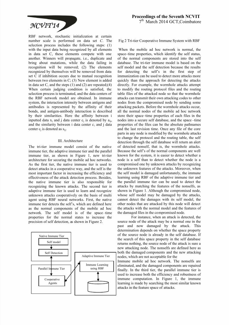
8/12/2019 various papers in our college
http://slidepdf.com/reader/full/various-papers-in-our-college 67/69
Proceedings of the Seventh NCVIT7th March 2014 GCT,Coimbatore
RBF network, stochastic initialization at certainnumber scale is performed on data set C . Theselection process includes the following steps: (1)with the input data being recognized by all elementsin data set C, these elements compete with one
another. Winners will propagate, i.e., duplicate and bring about mutations, while the data failing inrecognition will be removed; (2) The elementsrecognized by themselves will be removed from dataset C if inhibition occurs due to mutual recognition
between two elements in C; (3) New element is addedin data set C, and the steps (1) and (2) are repeated;(4)When certain judging condition is satisfied, theselection process is terminated, and the data centers ofthe RBF network model are obtained. In immunesystem, the interaction intensity between antigens andantibodies is represented by the affinity of their
bonds, and antigen-antibody interaction is described by their similarities. Here the affinity between iinputted data xi and j data center c j is denoted by aij,and the similarity between i data center c i and j datacenter c j is denoted as sij.
III. Architecture
The tri-tier immune model consist of the nativeimmune tier, the adaptive immune tier and the parallelimmune tier, as shown in Figure 1, new tri-tierarchitecture for securing the mobile ad hoc networks.As the first tier, the native immune tier is used todetect attacks in a cooperative way, and the self is themost important factor in increasing the efficiency andeffectiveness of the attack detection process. Besides,the native immune tier is also responsible forrecognizing the known attacks. The second tier isadaptive immune tier is used to learn and recognizeunknown attacks cooperatively on the basis of multiagent using RBF neural networks. First, the nativeimmune tier detects the self’s, which are defined here
as the normal components of the mobile ad hocnetwork. The self model is of the space – time
properties for the normal states to increase the precision of self detection, as shown in Figure 2.
Fig 2 Tri-tier Cooperative Immune System with RBF
When the mobile ad hoc network is normal, thespace – time properties, which identify the self status,
of the normal components are stored into the selfdatabase. The tri-tier immune model is based on theself model and the self detection because the resultsfor detecting the self’s in the first step of
immunization can be used to detect more attacks morequickly than the approach for detecting the attacksdirectly. For example, the wormhole attacks attemptto modify the routing protocol files and the routingtable files of the attacked node so that the wormholeattacks can transmit their own attacking codes to othernodes from the compromised node by sending someattacking packets. Before the wormhole attacks occur,all the normal nodes of the mobile ad hoc networkstore their space – time properties of each files in thenodes into a secure self database, and the space – time
properties of the files can be the absolute pathnamesand the last revision time. Once any file of the core
parts in any node is modified by the wormhole attacksto change the protocol and the routing table, the selfdetection through the self database will return an alertof detected nonself, that is, the wormhole attacks.Because the self’s of the normal components are well
known for the system, it is easier to detect whether anode is a self than to detect whether the node is acompromised one by unknown attacks by recognizingthe unknown features of the attacks. Moreover, whenthe self model is damaged unfortunately, the immunelearning using RBF of the adaptive immune tier andthe parallel immune tier can be used to detect theattacks by matching the features of the nonselfs, asshown in Figure 1. Although the compromised node,whose self model may be damaged by the attacks,cannot detect the damages with its self model, theother nodes that are attacked by this node will detectthe attacks with the normal model and the features ofthe damaged files in the compromised node.
For instance, when an attack is detected, thesource node of the attack may be a normal one in the
past and now damaged by the attack. Thisdetermination depends on whether the space propertyof the source node is already in the self database. Ifthe search of this space property in the self databasereturns nothing, the source node of the attack is sure anew attacking node. The nonselfs are defined here as
both the damaged components and the new attackingnodes, which are not acceptable for theImmune mobile ad hoc network. The nonselfs areeliminated, and the damaged components are repairedfinally. In the third tier, the parallel immune tier isused to increase both the efficiency and robustness ofimmune computation. In Figure 1, the immune
learning is made by searching the most similar knownattacks in the feature space of attacks.
Native Immune Tier
Self model
Self Detection
Parallel Immune Tier
Cooperative
Agents
Adaptive Immune Tier
Immune Learning using RBF

8/12/2019 various papers in our college
http://slidepdf.com/reader/full/various-papers-in-our-college 68/69
Proceedings of the Seventh NCVIT7th March 2014 GCT,Coimbatore
In adaptive immune tier, Detection agent is the core ofthe architecture, its immune memory to find thedegree of similarity. Successful matching indicatesthat there are invasion behaviors, while not matchingshows that there is no record in immune memory, and
then the upper function will work. Upper function isused to contrast the codes of specified neighbor whichacts with protocols in strategy library, to identify theinvasion not found in underlying immune memory.Once invasion is discovered by Detection Agent, itwill send out directions to all neighbor nodes aroundthe intruder to stop forwarding all intruder messagesto isolate it from the network. Detection Agents areequivalent to T cells. Their main function is toidentify invaders (antigens), and to organize othernodes to carry out the attacks against the invaders.Detection Agents in some nodes are distributed indifferent parts of the network. With the nodes areroaming, they can keep the entire network undersurveillance. Detection Agent should not stay in eachnode. It simply uniformly distributes in network. AdHoc network is divided into small zones, and in eachzone, there is one Detection Agent in, which isresponsible for monitoring all nodes in this zone.Detection Agent is being mapped with RBF neuralnetwork approach as follows in Fig 3
Detection agent terminology of RBF neuralnetwork contains three layer input layer, hidden layerand output layer input layer x1,x2,xn contains antigenis simply fan-out, in hidden layer computation workwill be done. Here, the antibodies are present theweights correspond to cluster centre and the outputfunction is usually a Gaussian type. The third isoutput layer here the weighted sum is calculated.
Fig 3: Detection agent terminology of RBF neuralnetwork.
IV.Characteristics of tri-tier architecture
Cooperative immune systems are applied tosecurity architecture in the use of Agent technology
for the detection of abnormal behavior and activeresponse. There are following characteristics in thisarchitecture:
A) Protection against Collaborative Attack
Collaborative attacks in the mobile ad hocnetworks can cause more damages than individualattacks. Inspired by the human immune system, a tri-cooperative immune model is protection againstcollaborative attacks in the mobile ad hoc networks.In Adaptive immune tier, A Multi Agent system has
been adopted in the immune learning to performdetection in an efficient manner using RBF neuralnetwork. Based on the output, a counter attack agentis dispatched to surround the invaders and kill it usingthe killer agents.
B) Reduce Overhead
Monitor Agent stays in each node to keep allits neighbor nodes under surveillance. That’s to say,
one node will be repeatedly monitored by all neighborMonitor Agents. Monitor Agent sends all messagecodes of its neighbor nodes’ behaviors to Decision
Agent, which will make network overload. OurArchitecture is designed to use one Detection Agentin one-hop scope to monitor and make decision,which will decrease greatly the network’s load and
node burden.
The performance of the proposed framework willyield efficient Packet Delivery Ratio, throughput, thetraffic overhead, and the responsiveness of thesystem. By experimental, the results will confirm theeffectiveness of the proposed cooperative immunemodel in detecting and mitigating these collaborativeattacks from disrupting the protected mobile ad hocnetworks.
V. Conclusion and Future Work
Cooperative immune System was proposedto defend the ad hoc network under such collaborativeattacks as the black hole attacks and the wormhole
attacks. New tri-tier cooperative immunization-basedframework was designed to detect and immune agentwith RBF neural network approach to identify thenew attack in MANET network. The immune systemand the Agent technology, improves the existingsecurity model. The system has the characteristics ofdistribution, self-adaption, self-learning, andexpandability, and so on.The performance of the
proposed framework will yield efficient PacketDelivery Ratio, throughput, the traffic overhead, andthe responsiveness of the system. By experimental,the results will confirm the effectiveness of the
proposed cooperative immune model in detecting and
mitigating these collaborative attacks from disruptingthe protected mobile ad hoc networks.

8/12/2019 various papers in our college
http://slidepdf.com/reader/full/various-papers-in-our-college 69/69
Proceedings of the Seventh NCVIT7th March 2014 GCT,Coimbatore
For future works, it is interesting toevaluations of the issues such as tests against othercollaborative attacks, real-time identification of theself’s, complexity, optimization, and consumption arealso left for future work.
References
[1] Tao Gong and Bharat Bhargava ―Immunizing
mobile ad hoc networks against collaborative attacksusing cooperative immune model ― Security and
Communication Networks 2012. 58-68
[2] Xia Ye, Junshan Li,‖ A Security ArchitectureBased on Immune Agents for MANET‖
Proceedings of IEEE ICWCSC CONFERENCE,IEEE, 2010.
[3] Bhargava B, Zhang Y, Idika N, et al.Collaborative attacks in WiMAX networks. Securityand Communication Networks 2009; 2(5): 373 – 391.
[4] Y. Zhang and W. Lee, ―Intrusion Detection in
Wireless Ad- Hoc Networks,‖ Proceedings of the 6th
Annual International Conference on MobileComputing and Networking, MobiCom’ 2000, pp.
275-283.
[5] Ping Yi, Yiping Zhong, Shiyong Zhang, ―An
immunity-based security architecture for mobile AdHoc networks,‖ Journal of Electronics (China),
Vol.23 No.3, May 2006.
[6] Wang Yinglong, Wang Jizhi, Wang Merqin, GaoZhenming, ―An analysis technology of security
routing protocol for MANET,‖ Computer Engineering
and Application (china). Vol.23 December 2005.
[7] S. Sathyanath, F. Sahin, "AISIMAM – An AIS based intelligent multi agent model and its applicationto mine detection problem," In: Proceedings of the 1stInternational Conference on Artificial Immune
Systems, Canterbury, UK, 2002, pp. 9 – 11.
[8] Ramaswamy S, Fu H, Nygard K. Effect ofcooperative blackhole attack on mobile ad hocnetworks. In ICWN. 2005.
[9] Sarafijanovic S, Le Boudec JY. An artificialimmune system approach with secondary response formisbehaviour detection in mobile ad hoc networks.IEEE Transactions on Neural Networks 2005; 16(5):
1076 – 1087.
[10] Yu-Sung W, Foo B, Mei Y, Bagchi S.Collaborative intrusion detection system (CIDS): aframework for accurate and efficient IDS. InProceedings of Computer Security ApplicationsConference. 2003; 234 – 244.
[11] Ying Zhou, De-ling Zheng, Zhi-Liang Qiu, Guo-ya dong, "The application of RBF networks based onartificial Immune algorithm in the performance
prediction of steel bars," Journal of University ofScience and Technology Beijing, 2005, pp.23-26.
[12] Li Changrong, Qu Zuyu, Yang Dejun,"Clustering analysis of corrosive factors of soil,"Journal of Chinese Society for Corrosion andProtection, 1994, pp. 138-143.
[13] A.K.Ghosh and A.Schwartzbard.‖A study inusing neural networks for anamoly and misusedetection‖, Proceedings of The 8
th USENIX securitysymposium, 1999.
[14] Ziv Y, Ron N, Butovsky O, et al. Immune cellscontribute to the main- tenance of neurogenesis andspatial learning abilities in adulthood. Nature
Neuroscience 2006; 9: 268 – 275.
[15] R. Heady, G. Luger, A. Maccabe, and M.Servilla‖The Architecture of a network level intrusion
detection system.‖ Technical report, Computer
Science Department, UniversityOf New Mexico, August 1990.
[16] L. Zhou and Z. J. Haas. ―Securing ad- hocnetworks.‖ EEE Network, 13(6):24{30, Nov/Dec
1999.
[17] Lakshmi Venkatraman. ―Secured routing
protocol for ad-hoc networks.‖ Master's thesis,
University of Cincinnati, OH,March 2000.


![[Various Papers on Egypt for the Fayoum project] · [Various Papers on Egypt for the Fayoum project] Cairo, Egypt, UNICEF 1991 - Contents: Low cost technologies for drinking water](https://img.pdfslide.us/doc/110x75/60601eceb72d2a35397f10d9/various-papers-on-egypt-for-the-fayoum-project-various-papers-on-egypt-for-the.jpg)