Embed Size (px)
Citation preview
8Screws
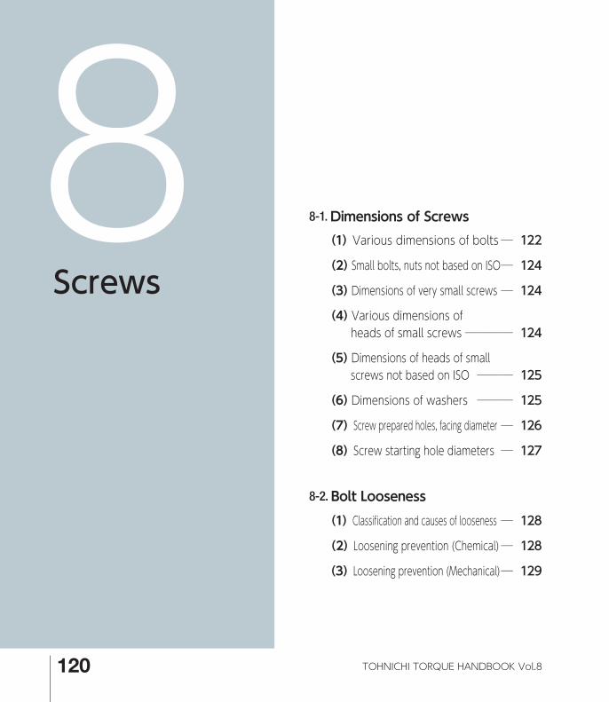
8-1. Dimensions of Screws (1) Various dimensions of bolts ─ 122
(2) Small bolts, nuts not based on ISO ─ 124
(3) Dimensions of very small screws ─ 124
(4) Various dimensions of heads of small screws ──── 124
(5) Dimensions of heads of small screws not based on ISO ─── 125
(6) Dimensions of washers ─── 125
(7) Screw prepared holes, facing diameter ─ 126
(8) Screw starting hole diameters ─ 127
8-2. Bolt Looseness (1) Classification and causes of looseness ─ 128
(2) Loosening prevention (Chemical) ─ 128
(3) Loosening prevention (Mechanical) ─ 129
120 TOHNICHI TORQUE HANDBOOK Vol.8
*08_P120-129_E.indd 120*08_P120-129_E.indd 120 14/06/09 10:3714/06/09 10:37

Names of Screws
Small screws with slits NutsCross-recessed pan screws Hexalobular screws
Hexagon set screwsHexagon socket head bolts Hexagon bolts
Cross-recessed countersunk screws
121Technical Data
Screws
TECHNICAL DATA
Chapter
8
*08_P120-129_E.indd 121*08_P120-129_E.indd 121 14/06/09 10:3714/06/09 10:37
Chapter Screws
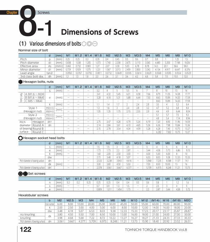
(1)Various dimensions of bolts
Dimensions of Screws8-1Nominal size of bolt
d [mm] M1 M1.2 M1.4 M1.6 M2 M2.5 M3 M3.5 M4 M5 M6 M8 M10Pitch p [mm] 0.25 0.25 0.3 0.35 0.4 0.45 0.5 0.6 0.7 0.8 1 1.25 1.5Pitch diameter d2 [mm] 0.838 1.038 1.205 1.373 1.740 2.208 2.675 3.110 3.545 4.480 5.350 7.188 9.026Eff ective area As [mm2] 0.460 0.732 0.983 1.27 2.07 3.39 5.03 6.78 8.78 14.2 20.1 36.6 58.0Minor diameter d1 [mm] 0.729 0.929 1.075 1.221 1.567 2.013 2.459 2.850 3.242 4.134 4.917 6.647 8.376Lead angle tanβ 0.0950 0.0767 0.0792 0.0811 0.0732 0.0649 0.0595 0.0614 0.0629 0.0568 0.0595 0.0554 0.05293rd class bolt dia. dh [mm] 1.3 1.5 1.8 2.0 2.6 3.1 3.6 4.2 4.8 5.8 7.0 10.0 12.0
Hexagon bolts, nuts
d [mm] M1 M1.2 M1.4 M1.6 M2 M2.5 M3 M3.5 M4 M5 M6 M8 M10s [mm] ─ ─ ─ 3.2 4 5 5.5 6 7 8 10 13 16Part class
A(M1.6 ~M24)e [mm]
─ ─ ─ 3.41 4.32 5.45 6.01 6.58 7.66 8.79 11.05 14.38 17.77B(M1.6 ~M64) ─ ─ ─ 3.28 4.18 5.31 5.88 6.44 7.50 8.63 10.89 14.20 17.59C(M5~M64) ─ ─ ─ ─ ─ ─ ─ ─ ─ 8.63 10.89 14.20 17.59
k [mm] ─ ─ ─ 1.1 1.4 1.7 2 2.4 2.8 3.5 4 5.3 6.4 Style 1
(Hexagon nut)m( ) [mm] ─ ─ ─ 1.3 1.6 2 2.4 2.8 3.2 4.7 5.2 6.8 8.4m( ) ─ ─ ─ 1.05 1.35 1.75 2.15 2.55 2.9 4.4 4.9 6.44 8.04
Style 2(Hexagon nut)
m( ) [mm] ─ ─ ─ ─ ─ ─ ─ ─ ─ 5.1 5.7 7.5 9.3m( ) ─ ─ ─ ─ ─ ─ ─ ─ ─ 4.8 5.4 7.14 8.94
Pitch diameter of bearing surface
Hexagon dn1 ─ ─ ─ 2.75 3.47 4.28 4.79 5.34 6.19 7.20 8.90 11.96 14.59Round A dn ─ ─ ─ 2.14 2.84 3.61 4.10 4.65 5.36 6.36 7.98 10.84 13.36Round B ─ ─ ─ 2.15 2.78 3.54 4.04 4.59 5.28 6.28 7.40 10.75 13.27Round C ─ ─ ─ ─ ─ ─ ─ ─ ─ 6.282 7.902 10.75 13.27
MAX
Min
Hexagon socket head bolts
d [mm] M1 M1.2 M1.4 M1.6 M2 M2.5 M3 M3.5 M4 M5 M6 M8 M10s [mm] ─ ─ ─ 1.5 1.5 2 2.5 ─ 3 4 5 6 8e [mm] ─ ─ ─ 1.73 1.73 2.3 2.87 ─ 3.44 4.58 5.72 6.86 9.15k [mm] ─ ─ ─ 1.60 2.00 2.50 3.00 ─ 4.00 5.00 6.00 8 10dw ─ ─ ─ 2.72 3.48 4.18 5.07 ─ 6.53 8.03 9.38 12.33 15.33
Pitch diameter of bearing surface dn ─ ─ ─ 2.533 3.238 3.843 4.616 ─ 5.968 7.235 8.588 11.57 14.1dk [mm] ─ ─ ─ 3.00 3.80 4.50 5.50 ─ 7.00 8.50 10.00 13 16
Pitch diameter of bearing surface dn' ─ ─ ─ 2.378 3.061 3.667 4.377 ─ 5.709 6.975 8.248 11.21 13.73
Hexalobular screws
b M2 M2.5 M3 M4 M5 M6 M8 M10 M12 (M14) M16 (M18) M20Hole number 6.00 8.00 10.00 20.00 25.00 30.00 45.00 50.00 55.00 60.00 70.00 80.00 90.00 k 2.00 2.50 3.00 4.00 5.00 6.00 8.00 10.00 12.00 14.00 16.00 18.00 20.00 dw 3.48 4.18 5.07 6.53 8.03 9.38 12.33 15.33 17.23 20.17 23.17 25.87 28.87
no knurling dk 3.80 4.50 5.50 7.00 8.50 10.00 13.00 16.00 18.00 21.00 24.00 27.00 30.00 knurling 3.98 4.68 5.68 7.22 8.72 10.22 13.27 16.27 18.27 21.33 24.33 27.33 30.33 Pitch diameter of bearing surface dn 3.061 3.667 4.377 5.709 6.975 8.248 11.21 13.73 15.90 18.40 20.92 23.52 26.51
Set screws
d [mm] M1 M1.2 M1.4 M1.6 M2 M2.5 M3 M3.5 M4 M5 M6 M8 M10n [mm] 0.2 0.2 0.25 0.25 0.25 0.4 0.4 0.5 0.6 0.8 1 1.2 1.6s [mm] ─ ─ ─ 0.7 0.9 1.3 1.5 ─ 2 2.5 3 4 5e [mm] ─ ─ ─ 0.809 1.011 1.454 1.73 ─ 2.3 2.87 3.44 4.58 5.72
MAX
Min
122 TOHNICHI TORQUE HANDBOOK Vol.8
*08_P120-129_E.indd 122*08_P120-129_E.indd 122 14/06/09 10:3714/06/09 10:37

M12 M14 M16 M18 M20 M22 M24 M27 M30 M33 M36 M39 M42 M45 M48 M52 M561.75 2 2 2.5 2.5 2.5 3 3 3.5 3.5 4 4 4.5 4.5 5 5 5.510.863 12.701 14.701 16.376 18.376 20.376 22.051 25.051 27.727 30.727 33.402 36.402 39.077 42.077 44.752 48.752 52.42884.3 115 157 192 245 303 353 459 561 694 817 976 1120 1310 1470 1760 203010.106 11.835 13.835 15.294 17.294 19.294 20.752 23.752 26.211 29.211 31.670 34.670 37.129 40.129 42.587 46.587 50.0460.0513 0.0501 0.0433 0.0486 0.0433 0.0391 0.0433 0.0381 0.0402 0.0363 0.0381 0.0350 0.0367 0.0340 0.0356 0.0326 0.033414.5 16.5 18.5 21.0 24.0 26.0 28.0 32.0 35.0 38.0 42.0 45.0 48.0 52.0 56.0 62.0 66.0
M12 M14 M16 M18 M20 M22 M24 M27 M30 M33 M36 M39 M42 M45 M48 M52 M5618 21 24 27 30 34 36 41 46 50 55 60 65 70 75 80 8520.03 23.36 26.75 30.14 33.53 37.72 39.98 ─ ─ ─ ─ ─ ─ ─ ─ ─ ─19.85 22.78 26.17 29.56 32.95 37.29 39.55 45.2 50.85 55.37 60.79 66.44 71.3 76.95 82.6 88.25 93.5619.85 22.78 26.17 29.56 32.95 37.29 39.55 45.2 50.85 55.37 60.79 66.44 71.3 76.95 82.6 88.25 93.567.5 8.8 10 11.5 12.5 14 15 17 18.7 21 22.5 25 26 28 30 33 3510.8 12.8 14.8 15.8 18 19.4 21.5 23.8 25.6 28.7 31 33.4 34 36 38 42 4510.37 12.1 14.1 15.1 16.9 18.1 20.2 22.5 24.3 27.4 29.4 31.8 32.4 34.4 36.4 40.4 43.412 14.1 16.4 17.6 20.3 21.8 23.9 26.7 28.6 32.5 34.7 ─ ─ ─ ─ ─ ─11.57 13.4 15.7 16.9 19 20.5 22.6 25.4 27.3 30.9 33.1 ─ ─ ─ ─ ─ ─16.86 19.48 22.10 24.95 28.03 31.22 33.27 37.94 42.16 45.81 50.48 54.70 58.92 63.59 68.26 73.83 78.5015.59 18.12 20.56 23.24 26.15 28.95 30.89 ─ ─ ─ ─ ─ ─ ─ ─ ─ ─15.51 17.86 20.30 22.98 25.89 28.76 30.70 35.09 39.00 42.42 46.70 50.62 54.20 58.58 62.97 68.28 72.5115.51 17.86 20.30 22.98 25.89 28.76 30.70 35.09 39.00 42.42 46.70 50.62 54.20 58.58 62.97 68.28 72.51
JIS B1180,B1181参照 円形座部外径DはJIS B1180参照M12 M14 M16 M18 M20 M22 M24 M27 M30 M33 M36 M39 M42 M45 M48 M52 M5610 12 14 ─ 17 ─ 19 ─ 22 ─ 27 ─ 32 ─ 36 ─ 4111.43 13.72 16 ─ 19.44 ─ 21.73 ─ 25.15 ─ 30.85 ─ 36.57 ─ 41.13 ─ 45.8312 14 16 ─ 20 ─ 24 ─ 30 ─ 36 ─ 42 ─ 48 ─ 5617.23 20.17 23.17 ─ 28.87 ─ 34.81 ─ 43.61 ─ 52.54 ─ 61.34 ─ 70.34 ─ 82.2616.31 18.84 21.37 ─ 27.11 ─ 32.17 ─ 40.21 ─ 48.25 ─ 55.84 ─ 64.33 ─ 75.3618 21 24 ─ 30 ─ 36 ─ 45 ─ 54 ─ 63 ─ 72 ─ 8415.90 18.40 20.92 ─ 26.51 ─ 31.53 ─ 39.46 ─ 47.47 ─ 54.94 ─ 63.44 ─ 74.43
M12 M14 M16 M18 M20 M22 M24 M27 M30 M33 M36 M39 M42 M45 M48 M52 M562 ─ ─ ─ ─ ─ ─ ─ ─ ─ ─ ─ ─ ─ ─ ─ ─6 ─ 8 ─ 10 ─ 12 ─ ─ ─ ─ ─ ─ ─ ─ ─ ─6.86 ─ 9.15 ─ 11.43 ─ 13.72 ─ ─ ─ ─ ─ ─ ─ ─ ─ ─
※d2:JIS B 0205、p:JIS B 0205、β:tanβ=p/πd2 See P.31 for more details
s k m
e
d n dn,dn1
Hexagon socket head bolts Set screws Hexalobular screws
e
s nk
dk dwdwdw
Hole number
Hexagon bolts, nuts
dn'
e
dk dw
s k
With chamfering and rounded edges
Various dimensions of bolts
123Technical Data
Screws
TECHNICAL DATA
Chapter
8
*08_P120-129_E.indd 123*08_P120-129_E.indd 123 14/06/09 10:3714/06/09 10:37

Chapter Screws
(2) Small bolts, nuts not based on ISO
d [mm] M8 M10 M12 (M14) M16 (M18) M20 (M22) M24 (M27) M30 (M33) M36 (M39)s [mm] 12 14 17 19 22 24 27 30 32 36 41 46 50 55
e [mm] 13.9 16.2 19.6 21.9 25.4 27.7 31.2 34.6 37 41.6 47.3 53.1 57.7 63.5k [mm] 5.5 7 8 9 10 12 13 14 15 17 19 21 23 25m [mm] 6.5 8 10 11 13 15 16 18 19 22 24 26 29 31m 5 6 7 8 10 11 12 13 14 16 18 20 21 23
Hexagon dn1 10.68 12.76 15.61 17.66 20.3 22.3 25.0 27.6 29.6 33.3 37.5 41.7 45.4 49.6 Round dn 10.03 12.06 14.82 16.55 19.07 21.1 23.6 26.1 28.1 31.1 35.2 39.2 42.7 46.8
Table 8-2. Small bolts, nuts
(3) Dimensions of very small screws
d M1 (M1.1) M1.2 (M1.4) M1.6 M1.8d2 0.838 0.938 1.038 1.205 1.373 1.573p 0.25 0.25 0.25 0.3 0.35 0.35
Small screws with slits tan β 0.0950 0.0848 0.0767 0.0792 0.0811 0.0708d1 0.729 0.829 0.929 1.075 1.221 1.421As 0.460 0.588 0.732 0.983 1.27 1.70a 0.32 ‒ 0.32 0.32 0.4 ‒
Set screws with slits a 0.2 ‒ 0.2 0.25 0.25 ‒Socket head bolts B ‒ ‒ ‒ (1.3) (1.5) ‒ Set screws B ‒ ‒ ‒ (0.7) (0.7) ‒
Table 8-3. Dimensions of very small screws
※ (See P.31 for more details of hexagon and round bearing surface)
Small screws with slits Set screws with slits
Hexagon socket head bolts Hexagon set screws ※ d1min: Root diameter, A1min: Area of section of root diameter Unit: [mm]
(4) Various dimensions of heads of small screws
M1.6 M2 M2.5 M3 (M3.5) M4 M5 M6 M8 M10 ⊕# ⊕ 0 0 1 1 2 2 2 3 4 4
⊖ Slit width ⊖= a 0.4 0.5 0.6 0.8 1 1.2 1.2 1.6 2 2.5
Pan screws D 3.2 4.0 5.0 5.6 7.00 8.00 9.50 12.00 16.00 20.00H 1.30 1.60 2.10 2.40 2.60 3.10 3.70 4.6 6.0 7.5
Countersunk screws D 3.0 3.8 4.7 5.5 7.30 8.40 9.30 11.30 15.80 18.30H 1 1.2 1.5 1.65 2.35 2.7 2.7 3.3 4.65 5
Table 8-4. Dimensions of heads of small screws
Pan screws Countersunk screws
Unit: [mm]
Small hexagon nuts, bolts
H
D
H
D
(二面幅)
B
(二面幅)
B
s k m
e
dn dn,dn1
a a
Widt
h acro
ss fl a
t
Widt
h acro
ss fl a
t
Dimensions of Screws8-1
124 TOHNICHI TORQUE HANDBOOK Vol.8
*08_P120-129_E.indd 124*08_P120-129_E.indd 124 14/06/09 10:3714/06/09 10:37

(5) Dimensions of heads of small screws not based on ISO
M2 (M2.2) M2.5 M3 (M3.5) M4 (M4.5) M5 M6 M8 ⊕# ⊕ 1(0) 1 1 2(1) 2 2 2 2 3 3
( ) Supports ISO ( ) Truss head ⊖ Slit width ⊖= a 0.6 0.6 0.8 0.8 1 1 1 1.2 1.2 1.6
Pan screws D 3.5 4 4.5 5.5 6 7 8 9 10.5 14H 1.3 1.5 1.7 2 2.3 2.6 2.9 3.3 3.9 5.2
Countersunk screws D 4 4.4 5 6 7 8 9 10 12 16(Spherical countersunk screws) H 1.2 1.3 1.45 1.75 2 2.3 2.55 2.8 3.4 4.4
Truss screws D 4.5 5 5.7 6.9 8.1 9.4 10.6 11.8 14 17.8H 1.2 1.3 1.5 1.9 2.2 2.5 2.8 3.1 3.7 4.8
Bind screws D 4.3 4.7 5.3 6.3 7.3 8.3 9.3 10.3 12.4 16.4H 1.2 1.3 1.5 1.9 2.2 2.5 2.8 3.1 3.7 4.8
Spherical screws D 3.5 4 4.5 5.5 6 7 8 9 10.5 14H 1.3 1.5 1.7 2 2.3 2.6 3 3.4 4 5.4
Table 8-5. Dimensions of heads of small screws
Pan screws
Unit: [mm]
(6) Dimensions of washersM2 (M2.2)M2.5 M3 (M3.5) M4 (M4.5) M5 M6 (M7) M8 M10 M12(M14)M16(M18)M20(M22)M24(M27)M30
d 2.2 2.4 2.7 3.2 3.7 4.3 4.8 5.3 6.4 ‒ 8.4 10.5 13 15 17 19 21 23 25 28 31Plain washers, D 4.5 4.5 5 6 7 8 9 9 11 ‒ 15 18 20 24 28 30 34 37 39 44 50small, round
t 0.3 0.5 0.5 0.5 0.5 0.5 0.8 1 1.6 ‒ 1.6 1.6 2 2.5 2.5 3 3 3 4 4 4d 2.2 2.4 2.7 3.2 3.7 4.3 4.8 5.3 6.4 ‒ 8.4 10.5 13 15 17 19 21 23 25 28 31
Plain washers, D 5 6 6 7 8 9 10 10 12 ‒ 16 20 24 28 30 34 37 39 44 50 56polished, round t 0.3 0.5 0.5 0.5 0.5 0.8 0.8 1 1.6 ‒ 1.6 2 2.5 2.5 3 3 3 3 4 4 4d 2.1 ‒ 2.6 3.1 3.6 4.1 4.6 5.1 6.1 7.1 8.2 10.2 12.2 14.2 16.2 18.2 20.2 22.5 24.5 27.5 30.5t 0.5 ‒ 0.6 0.7 0.8 1 1.2 1.3 1.5 1.6 2 2.5 3 3.5 4 4.6 5.1 5.6 5.9 6.8 7.5
Spring washers D 4.4 ‒ 5.2 5.9 6.6 7.6 8.3 9.2 12.2 13.4 15.4 18.4 21.5 24.5 28 31 33.8 37.7 40.3 45.3 49.9t ‒ ‒ ‒ ‒ ‒ ‒ ‒ ‒ 1.9 2.0 2.5 3.0 3.6 4.2 4.8 5.4 6.0 6.8 7.2 8.3 ‒D ‒ ‒ ‒ ‒ ‒ ‒ ‒ ‒ 12.2 13.4 15.6 18.8 21.9 24.7 28.2 31.4 34.4 38.3 41.3 46.7 ‒
※ d: Plain washer inner dia. Unit: [mm]
Table 8-6. Dimensions of washers
No.2
No.3
Plain washers, small, round Plain washers, polished, round Spring washers
Countersunk screws (Spherical countersunk screws) Truss screws Bind screws Spherical screws
t
d D
t
d D
d D
2t
H
D
H
D D
H
D
H
D
H
125Technical Data
Screws
TECHNICAL DATA
Chapter
8
*08_P120-129_E.indd 125*08_P120-129_E.indd 125 14/06/09 10:3714/06/09 10:37

Chapter Screws
Dimensions of Screws 8-1 (7) Screw prepared holes, facing diameters Nominal
size of screw
Bolt hole diameter d’ Chamfering
e Facing diameter D’
1st class
2nd class
3rd class
4th class (1)
M1 1.1 1.2 1.3 - 0.2 3M1.2 1.3 1.4 1.5 - 0.2 4M1.4 1.5 1.6 1.8 - 0.2 4M1.6 1.7 1.8 2 - 0.2 5
※M1.7 1.8 2 2.1 - 0.2 5M1.8 2.0 2.1 2.2 - 0.2 5M2 2.2 2.4 2.6 - 0.3 7M2.2 2.4 2.6 2.8 - 0.3 8
※M2.3 2.5 2.7 2.9 - 0.3 8M2.5 2.7 2.9 3.1 - 0.3 8
※M2.6 2.8 3 3.2 - 0.3 8M3 3.2 3.4 3.6 - 0.3 9M3.5 3.7 3.9 4.2 - 0.3 10M4 4.3 4.5 4.8 5.5 0.4 11M4.5 4.8 5 5.3 6 0.4 13M5 5.3 5.5 5.8 6.5 0.4 13M6 6.4 6.6 7 7.8 0.4 15M7 7.4 7.6 8 - 0.4 18M8 8.4 9 10 10 0.6 20M10 10.5 11 12 13 0.6 24M12 13 13.5 14.5 15 1.1 28M14 15 15.5 16.5 17 1.1 32M16 17 17.5 18.5 20 1.1 35M18 19 20 21 22 1.1 39M20 21 22 24 25 1.2 43M22 23 24 26 27 1.2 46M24 25 26 28 29 1.2 50M27 28 30 32 33 1.7 55M30 31 33 35 36 1.7 62M33 34 36 38 40 1.7 66M36 37 39 42 43 1.7 72M39 40 42 45 46 1.7 76M42 43 45 48 - 1.8 82M45 46 48 52 - 1.8 87M48 50 52 56 - 2.3 93M52 54 56 62 - 2.3 100M56 58 62 66 - 3.5 110M60 62 66 70 - 3.5 115M64 66 70 74 - 3.5 122M68 70 74 78 - 3.5 127
Note: 1. 4th class is appropriate mainly for cast extracting holes. 2. Figures in bold are not prescribed in ISO 273. 3. The nominal sizes of ※ screws are not included in ISO meter screws of ISO 261.
Table 8-7. Bolt hole diameters, facing diameters
Unit: [mm]
90°e
d′
90° e
d′
D′
126 TOHNICHI TORQUE HANDBOOK Vol.8
*08_P120-129_E.indd 126*08_P120-129_E.indd 126 14/06/09 10:3714/06/09 10:37

(8) Screw starting hole diameters Screw Facing hole diameter (2) Ref.: Female screw inner diameter (3)
Nominal size of screw
Outside diameter d
Pitch P
(1)Standard catching height H1
System Max. permissible dimension
90 85 80 75 70Minimum permissible dimension
4H (Below M1.4) 5H (Over M1.6) 1st class
5H (Below M1.4) 6H (Over M1.6) 2nd class
7H 3rd class
M1 1.0 0.25 0.135 0.76 0.77 0.78 0.80 0.81 0.729 0.774 0.785 -M1.1 1.1 0.25 0.135 0.86 0.87 0.88 0.90 0.91 0.829 0.874 0.885 -M1.2 1.2 0.25 0.135 0.96 0.97 0.98 1.00 1.01 0.929 0.974 0.985 -M1.4 1.4 0.3 0.162 1.11 1.12 1.14 1.16 1.17 1.075 1.128 1.142 -M1.6 1.6 0.35 0.189 1.26 1.28 1.30 1.32 1.33 1.221 1.301 1.321 -M1.8 1.8 0.35 0.189 1.46 1.48 1.50 1.52 1.53 1.421 1.501 1.521 -M2 2.0 0.4 0.217 1.61 1.63 1.65 1.68 1.70 1.567 1.657 1.679 -M2.2 2.2 0.45 0.244 1.76 1.79 1.81 1.83 1.86 1.713 1.813 1.838 -M2.5 2.5 0.45 0.244 2.06 2.09 2.11 2.13 2.16 2.013 2.113 2.138 -M3 3.0 0.5 0.271 2.51 2.54 2.57 2.59 2.62 2.459 2.571 2.599 2.639M3.5 3.5 0.6 0.325 2.92 2.95 2.98 3.01 3.05 2.850 2.975 3.010 3.050
M4 4.0 0.7 0.379 3.32 3.36 3.39 3.43 3.47 3.242 3.382 3.422 3.466M4.5 4.5 0.75 0.406 3.77 3.81 3.85 3.89 3.93 3.688 3.838 3.878 3.924M5 5.0 0.8 0.433 4.22 4.26 4.31 4.35 4.39 4.134 4.294 4.334 4.384M6 6.0 1 0.541 5.03 5.08 5.13 5.19 5.24 4.917 5.107 5.153 5.217M7 7.0 1 0.541 6.03 6.08 6.13 6.19 6.24 5.917 6.107 6.153 6.217M8 8.0 1.25 0.677 6.78 6.85 6.92 6.99 7.05 6.647 6.859 6.912 6.982M9 9.0 1.25 0.677 7.78 7.85 7.92 7.99 8.05 7.647 7.859 7.912 7.982
M10 10.0 1.5 0.812 8.54 8.62 8.70 8.78 8.86 8.376 8.612 8.676 8.751M11 11.0 1.5 0.812 9.54 9.62 9.70 9.78 9.86 9.376 9.612 9.676 9.751M12 12.0 1.75 0.947 10.3 10.4 10.5 10.6 10.7 10.106 10.371 10.441 10.531M14 14.0 2 1.083 12.1 12.2 12.3 12.4 12.5 11.835 12.135 12.210 12.310M16 16.0 2 1.083 14.1 14.2 14.3 14.4 14.5 13.835 14.135 14.210 14.310M18 18.0 2.5 1.353 15.6 15.7 15.8 16.0 16.1 15.294 15.649 15.774 15.854M20 20.0 2.5 1.353 17.6 17.7 17.8 18.0 18.1 17.294 17.649 17.744 17.854M22 22.0 2.5 1.353 19.6 19.7 19.8 20.0 20.1 19.294 19.649 19.744 19.854M24 24.0 3 1.624 21.1 21.2 21.4 21.6 21.7 20.752 21.152 21.252 21.382M27 27.0 3 1.624 24.1 24.2 24.4 24.6 24.7 23.752 24.152 24.252 24.382
M30 30.0 3.5 1.894 26.6 26.8 27.0 27.2 27.3 26.211 26.661 26.771 26.921M33 33.0 3.5 1.894 29.6 29.8 30.0 30.2 30.3 29.211 29.661 29.771 29.921M36 36.0 4 2.165 32.1 32.3 32.5 32.8 33.0 31.670 32.145 32.270 32.420M39 39.0 4 2.165 35.1 35.3 35.5 35.8 36.0 34.670 35.145 35.270 35.420M42 42.0 4.5 2.436 37.6 37.9 38.1 38.3 38.6 37.129 37.659 37.799 37.979M45 45.0 4.5 2.436 40.6 40.9 41.1 41.3 41.6 40.129 40.659 40.799 40.979M48 48.0 5 2.706 43.1 43.4 43.7 43.9 44.2 42.587 43.147 43.297 43.487
M52 52.0 5 2.706 47.1 47.4 47.7 47.9 48.2 46.587 47.147 47.297 47.487M56 56.0 5.5 2.977 50.6 50.9 51.2 51.5 51.8 50.046 50.646 50.796 50.996M60 60.0 5.5 2.977 54.6 54.9 55.2 55.5 55.8 54.046 54.646 54.796 54.996M64 64.0 6 3.248 58.2 58.5 58.8 59.1 59.5 57.505 58.135 58.305 58.505M68 68.0 6 3.248 62.2 62.5 62.8 63.1 63.5 61.505 62.135 62.305 62.505
Table 8-8. Screw starting hole diameters
Remarks: Figures in bold on the left side of the line, line, and line are prescribed in each JIS B 0209. 4H (below M1.4), 5H (above M1.6) or fi rst class, 5H (below M1.4), 6H (above M1.6) or second- class and 7H or third class show they are within the permissible dimension of the female inner diameter. Note: (1) H1=0.541266P (2) Screw prepared hole = d - 2 x H1 (Catching rate/100)
Unit: [mm]
127Technical Data
Screws
TECHNICAL DATA
Chapter
8
*08_P120-129_E.indd 127*08_P120-129_E.indd 127 14/06/09 10:3714/06/09 10:37
Chapter Screws
(1)Classifi cation and causes of looseness
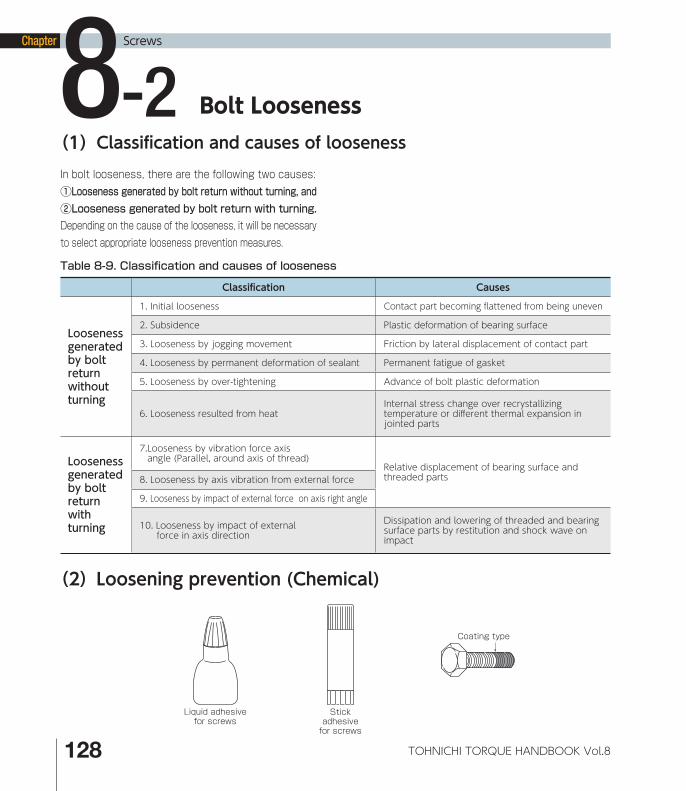
Bolt Looseness8-2In bolt looseness, there are the following two causes:①Looseness generated by bolt return without turning, and②Looseness generated by bolt return with turning.Depending on the cause of the looseness, it will be necessary to select appropriate looseness prevention measures.
Table 8-9. Classifi cation and causes of looseness
Classifi cation Causes
Looseness generated by bolt return without turning
1. Initial looseness Contact part becoming fl attened from being uneven
2. Subsidence Plastic deformation of bearing surface
3. Looseness by jogging movement Friction by lateral displacement of contact part
4. Looseness by permanent deformation of sealant Permanent fatigue of gasket
5. Looseness by over-tightening Advance of bolt plastic deformation
6. Looseness resulted from heatInternal stress change over recrystallizing temperature or diff erent thermal expansion in jointed parts
Looseness generated by bolt return with turning
7. Looseness by vibration force axis angle (Parallel, around axis of thread)
Relative displacement of bearing surface and threaded parts8. Looseness by axis vibration from external force
9. Looseness by impact of external force on axis right angle
10. Looseness by impact of external force in axis direction
Dissipation and lowering of threaded and bearing surface parts by restitution and shock wave on impact
(2)Loosening prevention (Chemical)
Stickadhesivefor screws
Liquid adhesivefor screws
Coating type
128 TOHNICHI TORQUE HANDBOOK Vol.8
*08_P120-129_E.indd 128*08_P120-129_E.indd 128 14/06/09 10:3714/06/09 10:37

Method of using check nut First tighten the lower nut to about 80% of the specified torque. Then, tighten the upper nut to 100% of the specified torque. This generates a reactive force between the two nuts and prevents them from becoming loose. If the load capacity of the nuts is likely to cause a problem, use the thicker one on top as shown in fi gure (b).
(3)Loosening prevention (Mechanical)Table 8-10. Preventing loose joints
Methods of using elastic washersBelleville spring washer Spring washer Claw spring washer Toothed washer
(a) (b)
Method of using small screw Method of using a claw or wire
Caulking
Methods to bend or calk part of the washer CalkingClaw washer Tongued washer
Bending Key channel CaulkingBending
Bending
Method to apply part of the material to the side of the nut Method of using split cotter
Method to use power applied to the bearing surface
Method of deforming
Method of fi lling nylon Method to use force-loosening check nut
Expansion channel(4-6 places)
NylonCaulkingNylon
129Technical Data
Screws
TECHNICAL DATA
Chapter
8
*08_P120-129_E.indd 129*08_P120-129_E.indd 129 14/06/09 10:3714/06/09 10:37


![ME 312 Mechanical Machine Design [Screws, Bolts, Nuts]](https://img.pdfslide.us/doc/110x75/58abead91a28ab504e8b545f/me-312-mechanical-machine-design-screws-bolts-nuts.jpg)