Embed Size (px)
Citation preview
1
VARIATION OF ROOT BENDING STRESS WITH HOB NOSE RADIUS AND
PROTUBERANCE BASED ON ISO AND FEM METHODS FOR SPUR
GEARS
V. Sridhar*, R. Malik and Prakher Sharma
Product Design Development, Eicher Tractors (A Unit of TAFE Motors and Tractors Limited)
*Corresponding Author, Tel-91-7480-407680, [email protected]
Abstract:-Tooth Bending Strength of Spur gears depends on the form factor YF and stress correction
factor YS in accordance with ISO 6336 for basic rack profiles with and without undercut. The chord
and radius at the critical section varies with the hob nose radius and affects the form factor YF and
stress correction factor YS. It is assumed that the root fillet is generated during the pre-treatment
itself and the flank is generated during the subsequent shaving process. Comparison between the
stresses calculated by the standard method and stresses calculated using FEM is depicted.
Keywords-: Theory of Gearing, Root Fillet, FEM, Fillet and Involute generation
INTRODUCTION
The tooth bending strength of spur gears is one of the basic criteria for the design of gears. ISO 6336
outlines the procedure for calculating the nominal and local tooth root stresses. The nominal tooth
root stress depends on YF (tooth form factor), YS (stress correction factor) and Y (Helix angle factor).
The basic relation of the nominal tooth root stress is given by equation (1) [5].
YYYmb
FSF
nf
tF 0 (1)
and the local tooth root stress is given by equation (2).
FFvAFF KKKK0 (2)
The geometry of the tooth root fillet determines YF and YS.
GEOMETRY OF TOOTH ROOT FILLET AND INVOLUTE
The geometry of the gear tooth root and the involute is based on the cutter path relative to the gear
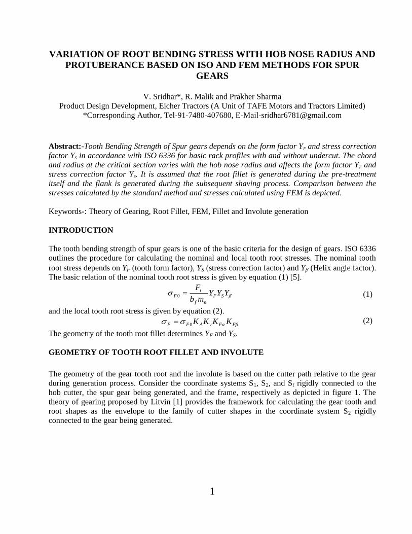
during generation process. Consider the coordinate systems S1, S2, and Sf rigidly connected to the
hob cutter, the spur gear being generated, and the frame, respectively as depicted in figure 1. The
theory of gearing proposed by Litvin [1] provides the framework for calculating the gear tooth and
root shapes as the envelope to the family of cutter shapes in the coordinate system S2 rigidly
connected to the gear being generated.

2
FIGURE 1: Gear Blank, hob and Fixed Coordinate System
The cutter surface 1 is represented in parametric form in S1 as [1], [2].
1
1111 ,,,,,, Cuzuyuxur (3)
011
r
u
r
2121 , uuu
Where 1C denotes that ,1 ur is a regular surface which has continuous derivatives to at least the
first order. The relative motion of 1 with respect to coordinate system S2 generates the family 2 of
generating surface 1 [1], [2].
The family of surfaces 2 in coordinate system S2 is represented by
,,, 1212 rMur (4)
Where
21M is the coordinate transformation from coordinate system S1 to S2.
In addition to the above set of equations, there exists an equation of meshing which should be
satisfied. The equation of meshing ensures that for any the generating surface 1 should not lose
its contact with the generated surface 2 because the contact of the two surfaces must be continuous
[1], [2]. The equation of meshing in coordinate system Sf is given by
0)12(
11 vN
where 1N is the normal to the cutter profile and )12(
1v is the relative sliding velocity between the cutter
and the gear blank, both in coordinate system S1.

3
FIGURE 2: Protuberance Hob Geometry
Figure 2 shows the normal profile of a hob. The hob can be divided into four segments, straight line
segment EF, straight line segment DE, arc BD and straight line segment AB. The involute profile is
generated by the straight line segment EF. The root circle of gear is generated by the line segment
AB. Any point of line segment EF can be represented in coordinate system S1 as
sin2
1 us
x , cos1 uy , 21 uuu (5)
where the range of u is
coscos
aPprPfP hu
hh
(6)
Therefore
1
cos
sin2
1
, 1
1
1
u
us
y
x
ur (7)
The transformation matrix from coordinate system S1 to S2 is given as
100
cossincossin
sincossincos
21
r
r
M (8)
Where
r is the pitch circle radius of the gear.
The equation for meshing in the coordinate system S1 can be represented as
01
11
1
11
yx N
yY
N
xX (9)
0, 11 YrX are the coordinates of the instantaneous center of rotation in coordinate system S1
and TN 0sincos1 is the normal vector to the cutter surface.

4
The following system of equations gives the pre-shaved involute
1
cos
sin2
100
cossincossin
sincossincos
,,2
u
us
r
r
ur (10)
0sinsin2
, rs
uuf (11)
The set of equation becomes
sincossincos2
2 rus
x (12)
cossincossin2
2 rus
y (13)
0sinsin2
rs
u (14)
sin
cossin
2
sin
cossin
2
r
hs
r
hhsaP
prPfP
(15)
ROOT FILLET GENRATION
The envelope to the arc BD in the coordinate system S2 gives the root fillet of the spur gear. The
center of the arc in coordinate system S1 is denoted by ),( baC where
cos
1sintantantan
2prPfP hh
sa (16)
fPhb (17)
FIGURE 3: Hob Nose Radius
As shown in figure 3 any point at angle on arc BD in coordinate system S1 is given by
1
cos
sin
1
1
1
1
b
a
y
x
r f
f
f (18)
Transforming from coordinate system S1 to S2 gives the tooth root profile in S2.
ff rMr 1212 (19)
5
The normal vector to the generating cutter arc BD is given by T0cossin
The equation of meshing in coordinate system S1 becomes
01
11
1
11
y
f
x
f
N
yY
N
xX (20)
The resulting system of equations, which give the tooth root profile in coordinate system S2, is
sincossinsincos2 rbax f (21)
cossincoscossin2 rbay f (22)
0tan bar (23)
r
ba
r
a
tan
(24)
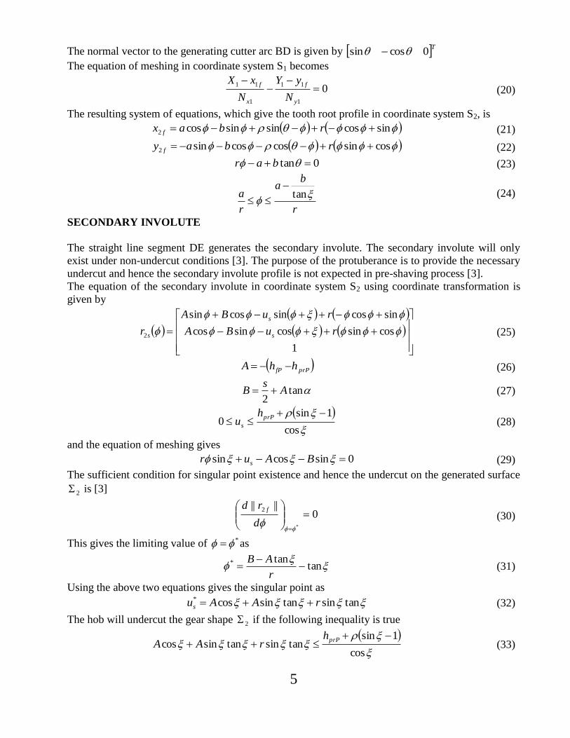
SECONDARY INVOLUTE
The straight line segment DE generates the secondary involute. The secondary involute will only
exist under non-undercut conditions [3]. The purpose of the protuberance is to provide the necessary
undercut and hence the secondary involute profile is not expected in pre-shaving process [3].
The equation of the secondary involute in coordinate system S2 using coordinate transformation is
given by
1
cossincossincos
sincossincossin
2
ruBA
ruBA
r s
s
s (25)
prPfP hhA (26)
tan2
As
B (27)
cos
1sin0
prP
s
hu (28)
and the equation of meshing gives
0sincossin BAur s (29)
The sufficient condition for singular point existence and hence the undercut on the generated surface
2 is [3]
0||||
*
2
d
rd f (30)
This gives the limiting value of * as
tantan*
r
AB (31)
Using the above two equations gives the singular point as
tansintansincos* rAAus (32)
The hob will undercut the gear shape 2 if the following inequality is true
cos
1sintansintansincos
prPhrAA (33)
6
At this value of the secondary profile angle, the root fillet is generated as the cutter „rolls
out‟ the root rather than as it „rolls into‟ the root [3].
r
hr fP
2
4sin
2
1
(34)
The relation, which governs the minimum value of secondary pressure angle
prP
prP
hh 1sinsin1 1 (35)
ROOT AND TIP DIAMETER
Line segment AB generates the root diameter. The generated root diameter is tangent to the root
fillet and theory of gearing gives the root profile. The hob used for the generation of the gear profile
is assumed to be a non-topping hob and hence the Tip diameter of the gear is determined by the gear
blank diameter. The determination of root and tip diameter profile also follows the same calculation
procedure as developed for the gear involute and the gear root profiles.
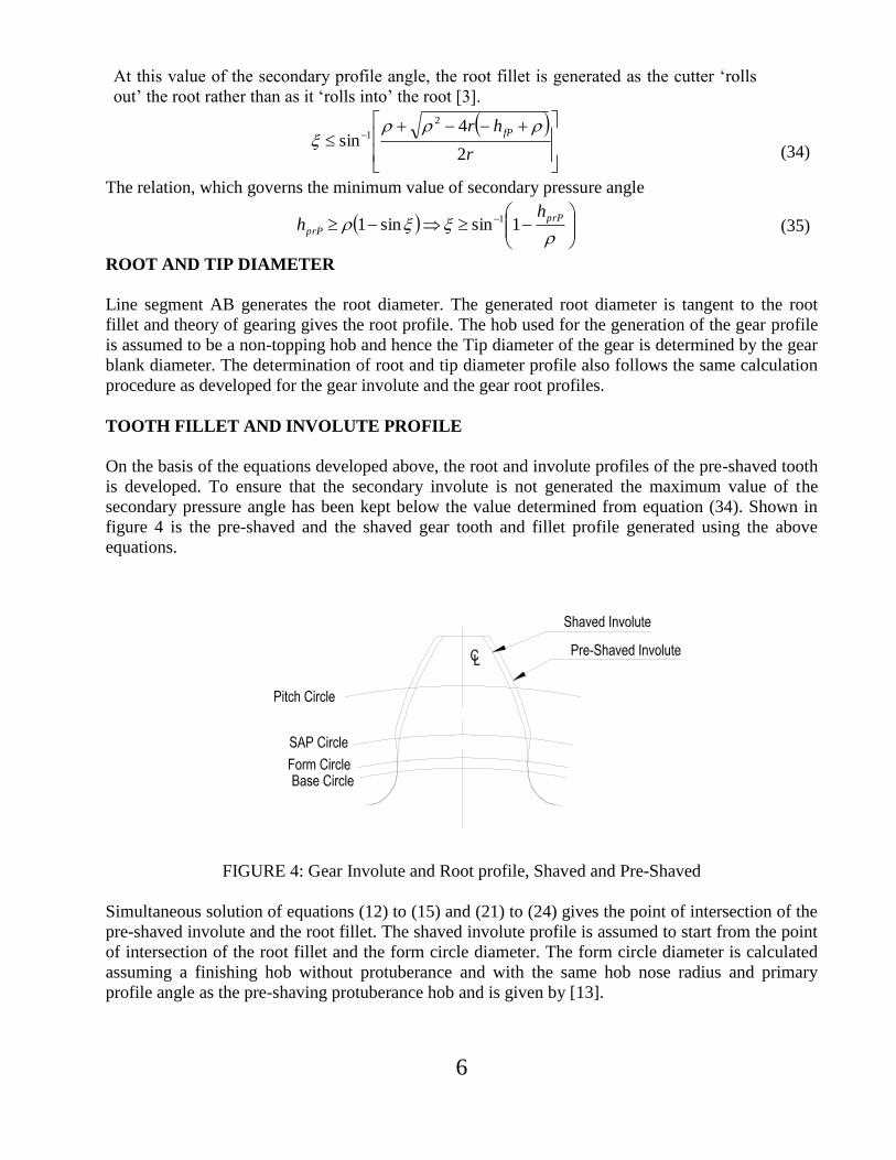
TOOTH FILLET AND INVOLUTE PROFILE
On the basis of the equations developed above, the root and involute profiles of the pre-shaved tooth
is developed. To ensure that the secondary involute is not generated the maximum value of the
secondary pressure angle has been kept below the value determined from equation (34). Shown in
figure 4 is the pre-shaved and the shaved gear tooth and fillet profile generated using the above
equations.
FIGURE 4: Gear Involute and Root profile, Shaved and Pre-Shaved
Simultaneous solution of equations (12) to (15) and (21) to (24) gives the point of intersection of the
pre-shaved involute and the root fillet. The shaved involute profile is assumed to start from the point
of intersection of the root fillet and the form circle diameter. The form circle diameter is calculated
assuming a finishing hob without protuberance and with the same hob nose radius and primary
profile angle as the pre-shaving protuberance hob and is given by [13].
7
2
2
2tan
222
c
fc
f
Nf hdh
dd
d
(36)
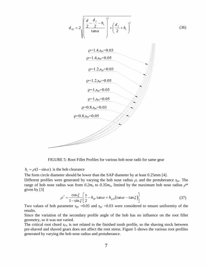
FIGURE 5: Root Fillet Profiles for various hob nose radii for same gear
)sin1( ch is the hob clearance
The form circle diameter should be lower than the SAP diameter by at least 0.25mm [4].
Different profiles were generated by varying the hob nose radius , and the protuberance spr. The
range of hob nose radius was from 0.2mn to 0.35mn, limited by the maximum hob nose radius *
given by [3]
tantantan
2sin1
cos*
prPfP hhs
(37)
Two values of hob parameter spr =0.05 and spr =0.03 were considered to ensure uniformity of the
results.
Since the variation of the secondary profile angle of the hob has no influence on the root fillet
geometry, so it was not varied.
The critical root chord sFn is not related to the finished tooth profile, so the shaving stock between
pre-shaved and shaved gears does not affect the root stress. Figure 5 shows the various root profiles
generated by varying the hob nose radius and protuberance.

8
ROOT STRESS ANALYSIS FOR VARIOUS HOB NOSE RADIUS AND PROTUBERANCE
Based on the analysis developed above, gears made with different hob nose radii and protuberances
were compared for the magnitude of the root stresses. Both analytical predictions based on ISO 6336
and FEA analysis of the nominal tooth root stress was carried out. The ISO standard determines the
root stress point, which is tangent to the root fillet and subtends an angle of 30° with the tooth
centerline as depicted in figure 8. The parameters sFn, hFe and Fare calculated at this point. The
form factor represents the state of stress in the gear root assuming the gear tooth as a short
cantilever.
The calculation of form factor YF and stress correction factor YS as per ISO 6336 is outlined below.
n
n
Fn
Fen
n
Fe
F
m
s
m
h
Y
cos
cos6
2
(38)
n
n
n
pr
nfP
sh
saE
cos)sin1(
costan
2 (39)
where
qprspr
0prs where the gears are not undercut.
s Hob width at the generating line
nm
bG (40)
32
2
nn m
E
zH (41)
Hz
G
n
tan2
(42)
The critical root chord is given by
n
n
n
Fn
m
Gz
m
s
cos3
3sin (43)
Gz
G
mm nnn
F
2coscos
22
2
(44)
n
n
n
enFenee
n
Fe
m
Gz
m
d
m
h
cos3costansincos
2
1 (45)
Feh Bending Moment Arm
end Diameter at Highest Point of Single tooth Contact (HPSTC)
2
222
21
coscos
222
bn
nnbnan
en
d
z
ddd
z
zd
(46)
9
en
bnen
d
d1cos
e = angle subtended by chordal tooth thickness at HPSTC.
Fen Pressure Angle at HPSTC
coscos2
b
n
zz
nz Virtual Number of teeth
The stress correction factor YS is given by
a
sS qLY 13.02.1 (47)
where
L
as
qh
sL
F
Fns
Fe
Fn
3.221.1
1,
2,
1Y (48)
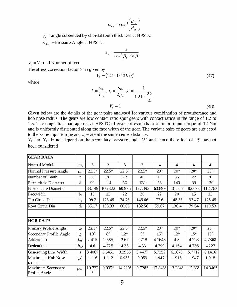
Given below are the details of the gear pairs analysed for various combination of protuberance and
hob nose radius. The gears are low contact ratio spur gears with contact ratios in the range of 1.2 to
1.5. The tangential load applied at HPSTC of gear corresponds to a pinion input torque of 12 Nm
and is uniformly distributed along the face width of the gear. The various pairs of gears are subjected
to the same input torque and operate at the same center distance.
YF and YS do not depend on the secondary pressure angle '' and hence the effect of '' has not
been considered
GEAR DATA Normal Module mn 3 3 3 3 4 4 4 4
Normal Pressure Angle n 22.5° 22.5° 22.5° 22.5° 20° 20° 20° 20°
Number of Teeth z 30 38 22 46 17 35 22 30
Pitch circle Diameter d 90 114 66 138 68 140 88 120
Base Circle Diameter 83.149 105.322 60.976 127.495 63.899 131.557 82.693 112.763
Facewidth bf 15 13 22 20 22 20 15 13
Tip Circle Dia da 99.2 123.45 74.76 146.66 77.6 148.33 97.47 128.45
Root Circle Dia df 85.17 108.83 60.66 132.56 59.67 130.4 79.54 110.53
HOB DATA Primary Profile Angle 22.5° 22.5° 22.5° 22.5° 20° 20° 20° 20°
Secondary Profile Angle 10° 8° 12° 9° 15° 12° 15° 12°
Addendum hfP 2.415 2.585 2.67 2.718 4.1648 4.8 4.228 4.7368
Dedendum haP 4.6 4.725 4.38 4.33 4.799 4.164 4.736 4.227
Generating Line Width s 3.4067 3.5451 3.3955 3.4477 5.7252 6.1876 5.7712 6.1416
Maximum Hob Nose
radius 1.116 1.112 0.955 0.959 1.947 1.918 1.947 1.918
Maximum Secondary
Profile Angle Max 10.732
°
9.995° 14.219° 9.728° 17.848° 13.334° 15.66° 14.346°
10
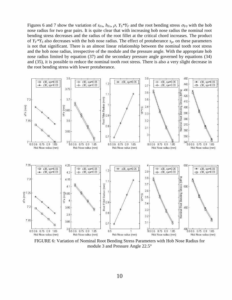
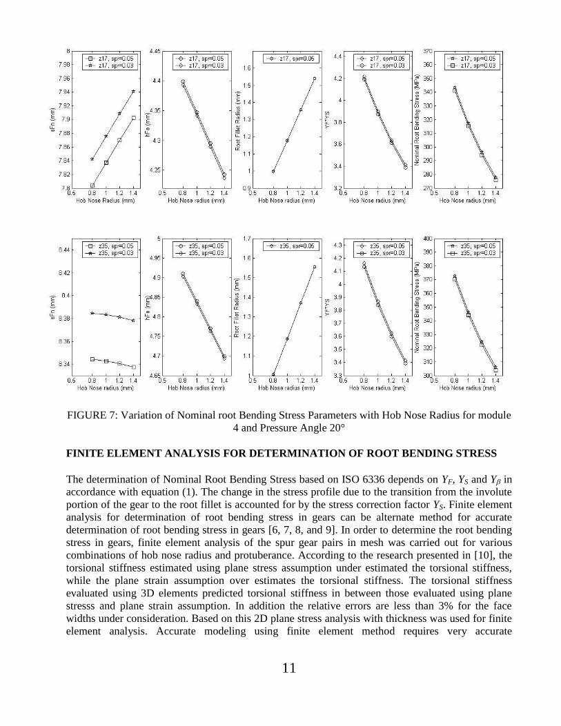
Figures 6 and 7 show the variation of sFn, hFe, , YS*YF and the root bending stress F0 with the hob
nose radius for two gear pairs. It is quite clear that with increasing hob nose radius the nominal root
bending stress decreases and the radius of the root fillet at the critical chord increases. The product
of YF*YS also decreases with the hob nose radius. The effect of protuberance spr on these parameters
is not that significant. There is an almost linear relationship between the nominal tooth root stress
and the hob nose radius, irrespective of the module and the pressure angle. With the appropriate hob
nose radius limited by equation (37) and the secondary pressure angle governed by equations (34)
and (35), it is possible to reduce the nominal tooth root stress. There is also a very slight decrease in
the root bending stress with lower protuberance.
FIGURE 6: Variation of Nominal Root Bending Stress Parameters with Hob Nose Radius for
module 3 and Pressure Angle 22.5°
11
FIGURE 7: Variation of Nominal root Bending Stress Parameters with Hob Nose Radius for module
4 and Pressure Angle 20°
FINITE ELEMENT ANALYSIS FOR DETERMINATION OF ROOT BENDING STRESS
The determination of Nominal Root Bending Stress based on ISO 6336 depends on YF, YS and Y in
accordance with equation (1). The change in the stress profile due to the transition from the involute
portion of the gear to the root fillet is accounted for by the stress correction factor YS. Finite element
analysis for determination of root bending stress in gears can be alternate method for accurate
determination of root bending stress in gears [6, 7, 8, and 9]. In order to determine the root bending
stress in gears, finite element analysis of the spur gear pairs in mesh was carried out for various
combinations of hob nose radius and protuberance. According to the research presented in [10], the
torsional stiffness estimated using plane stress assumption under estimated the torsional stiffness,
while the plane strain assumption over estimates the torsional stiffness. The torsional stiffness
evaluated using 3D elements predicted torsional stiffness in between those evaluated using plane
stresss and plane strain assumption. In addition the relative errors are less than 3% for the face
widths under consideration. Based on this 2D plane stress analysis with thickness was used for finite
element analysis. Accurate modeling using finite element method requires very accurate
12
determination of the involute and fillet profiles of the gears. To achieve this gear tooth and root
profile generated using the above developed equations were used for modeling.
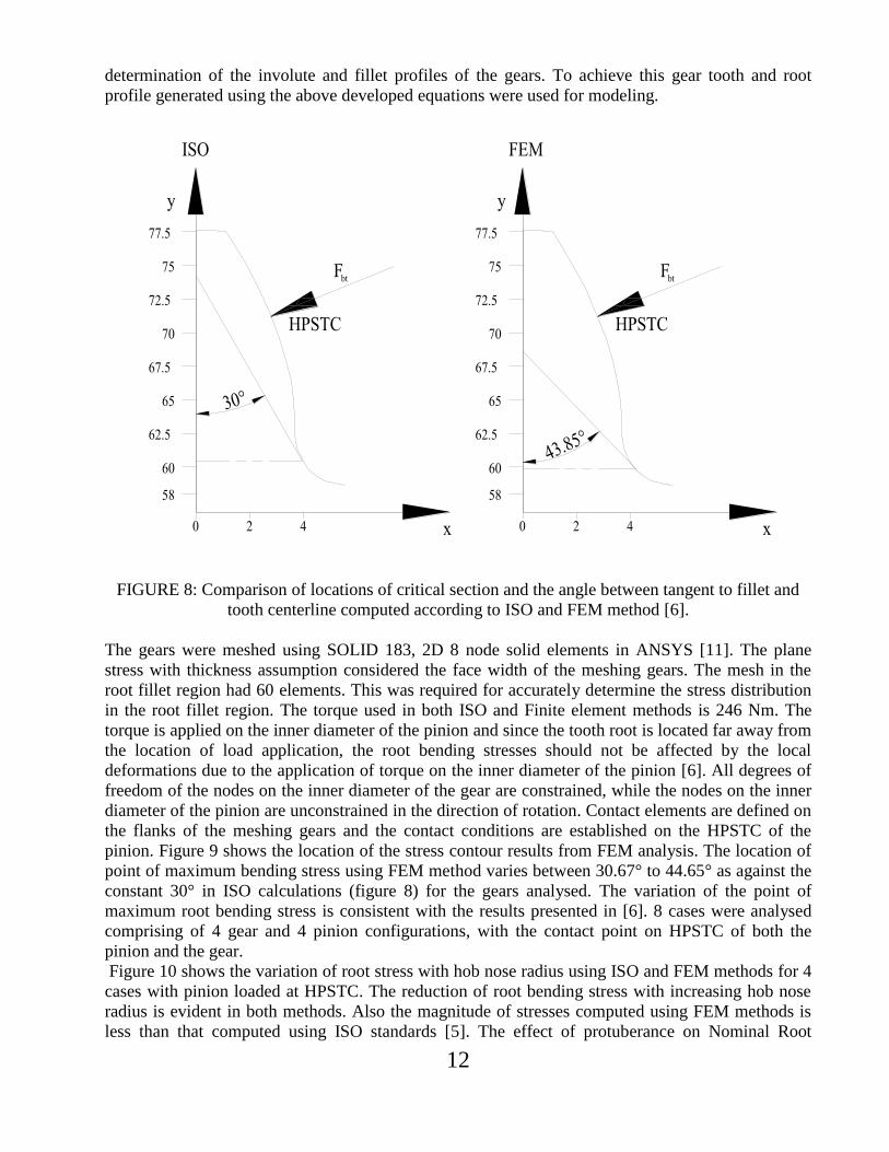
FIGURE 8: Comparison of locations of critical section and the angle between tangent to fillet and
tooth centerline computed according to ISO and FEM method [6].
The gears were meshed using SOLID 183, 2D 8 node solid elements in ANSYS [11]. The plane
stress with thickness assumption considered the face width of the meshing gears. The mesh in the
root fillet region had 60 elements. This was required for accurately determine the stress distribution
in the root fillet region. The torque used in both ISO and Finite element methods is 246 Nm. The
torque is applied on the inner diameter of the pinion and since the tooth root is located far away from
the location of load application, the root bending stresses should not be affected by the local
deformations due to the application of torque on the inner diameter of the pinion [6]. All degrees of
freedom of the nodes on the inner diameter of the gear are constrained, while the nodes on the inner
diameter of the pinion are unconstrained in the direction of rotation. Contact elements are defined on
the flanks of the meshing gears and the contact conditions are established on the HPSTC of the
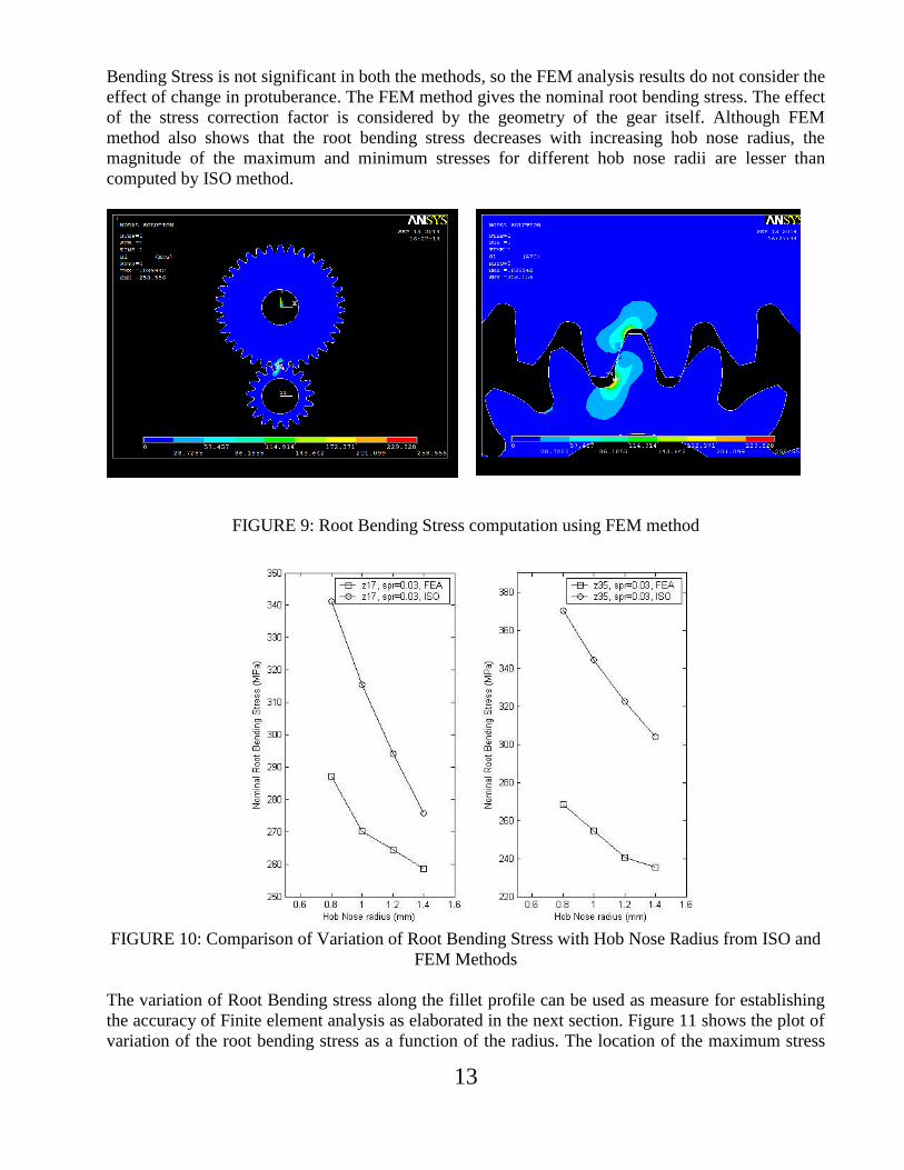
pinion. Figure 9 shows the location of the stress contour results from FEM analysis. The location of
point of maximum bending stress using FEM method varies between 30.67° to 44.65° as against the
constant 30° in ISO calculations (figure 8) for the gears analysed. The variation of the point of
maximum root bending stress is consistent with the results presented in [6]. 8 cases were analysed
comprising of 4 gear and 4 pinion configurations, with the contact point on HPSTC of both the
pinion and the gear.
Figure 10 shows the variation of root stress with hob nose radius using ISO and FEM methods for 4
cases with pinion loaded at HPSTC. The reduction of root bending stress with increasing hob nose
radius is evident in both methods. Also the magnitude of stresses computed using FEM methods is
less than that computed using ISO standards [5]. The effect of protuberance on Nominal Root
13
Bending Stress is not significant in both the methods, so the FEM analysis results do not consider the
effect of change in protuberance. The FEM method gives the nominal root bending stress. The effect
of the stress correction factor is considered by the geometry of the gear itself. Although FEM
method also shows that the root bending stress decreases with increasing hob nose radius, the
magnitude of the maximum and minimum stresses for different hob nose radii are lesser than
computed by ISO method.
FIGURE 9: Root Bending Stress computation using FEM method
FIGURE 10: Comparison of Variation of Root Bending Stress with Hob Nose Radius from ISO and
FEM Methods
The variation of Root Bending stress along the fillet profile can be used as measure for establishing
the accuracy of Finite element analysis as elaborated in the next section. Figure 11 shows the plot of
variation of the root bending stress as a function of the radius. The location of the maximum stress

14
progressively moves towards the root circle as the hob nose radius decreases, leading to an increase
in the angle from 30° as outlined in ISO-6336.
FIGURE 11: Variation of Root Bending Stress with Radius a) Pinion with 17 teeth b) Gear with 35
teeth
VERIFICATION OF FINITE ELEMENT ANALYSIS RESULTS
The experimental verification of stresses predicted using finite element method was not carried out.
Instead in order to establish the accuracy of the finite element method, Finite element analysis of
SAE symmetric test gear with 34 teeth and full rounded fillet were compared to the theoretical
results derived using LDP (Load Distribution Program from The Ohio State University) and
experimental results given in [12]. Finite element analysis using 2D plane stress with thickness, for
the base line geometry given in [12], was carried out. Figure 12 shows the load and boundary
condition of the test gear used in [12]. The gear is rotationally free. The load anvil was positioned
such that the load radius was 75.15mm.
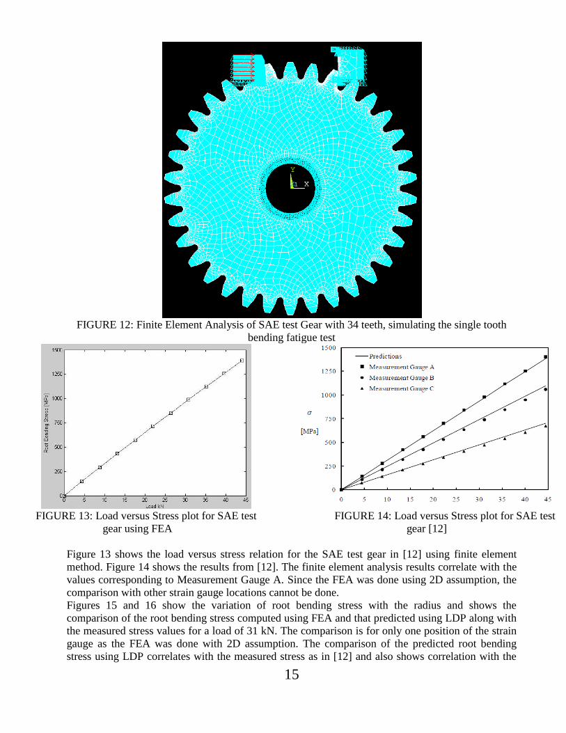
15
FIGURE 12: Finite Element Analysis of SAE test Gear with 34 teeth, simulating the single tooth
bending fatigue test
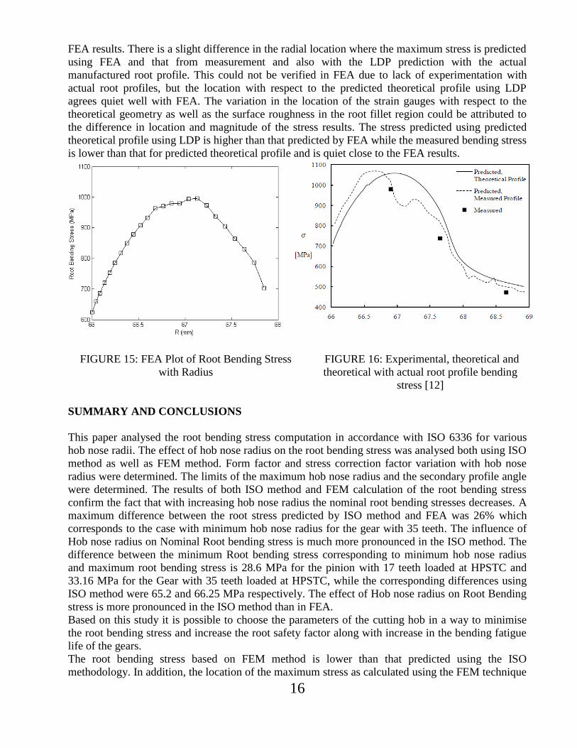
FIGURE 13: Load versus Stress plot for SAE test
gear using FEA
FIGURE 14: Load versus Stress plot for SAE test
gear [12]
Figure 13 shows the load versus stress relation for the SAE test gear in [12] using finite element
method. Figure 14 shows the results from [12]. The finite element analysis results correlate with the
values corresponding to Measurement Gauge A. Since the FEA was done using 2D assumption, the
comparison with other strain gauge locations cannot be done.
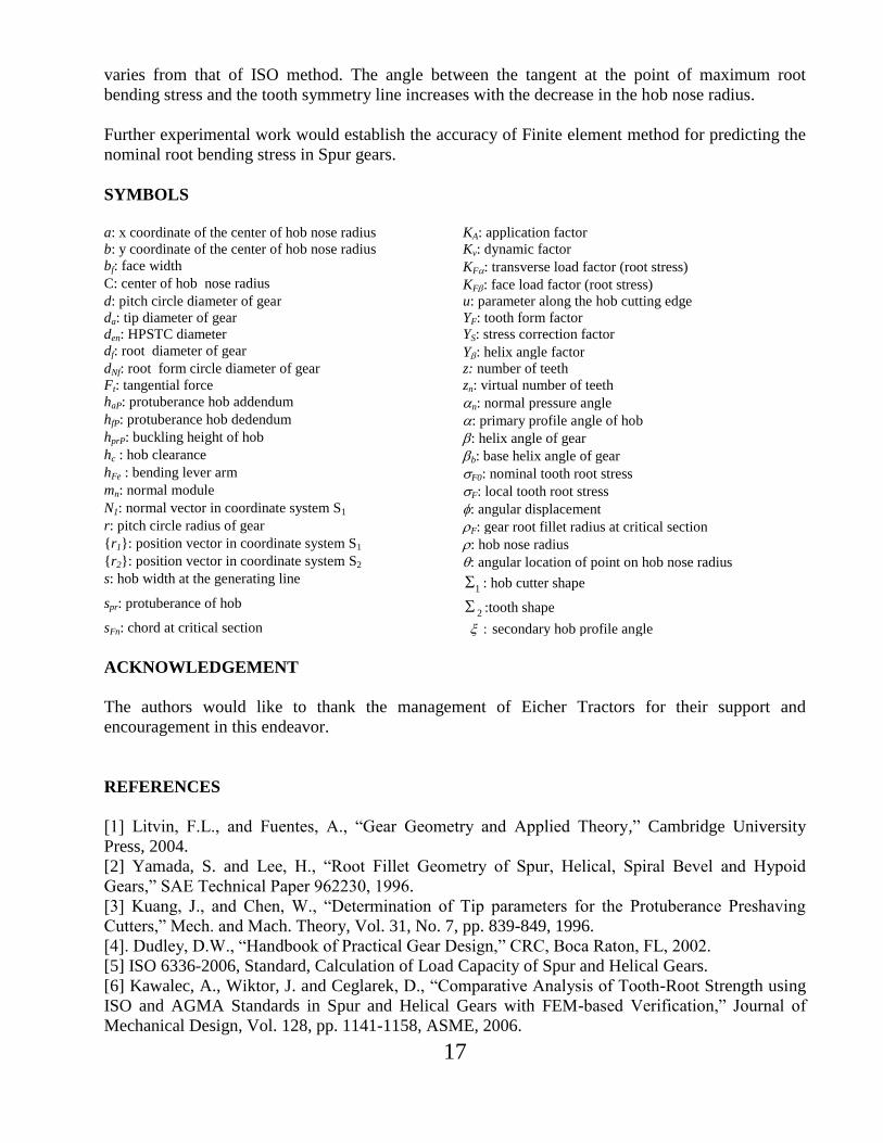
Figures 15 and 16 show the variation of root bending stress with the radius and shows the
comparison of the root bending stress computed using FEA and that predicted using LDP along with
the measured stress values for a load of 31 kN. The comparison is for only one position of the strain
gauge as the FEA was done with 2D assumption. The comparison of the predicted root bending
stress using LDP correlates with the measured stress as in [12] and also shows correlation with the
16
FEA results. There is a slight difference in the radial location where the maximum stress is predicted
using FEA and that from measurement and also with the LDP prediction with the actual
manufactured root profile. This could not be verified in FEA due to lack of experimentation with
actual root profiles, but the location with respect to the predicted theoretical profile using LDP
agrees quiet well with FEA. The variation in the location of the strain gauges with respect to the
theoretical geometry as well as the surface roughness in the root fillet region could be attributed to
the difference in location and magnitude of the stress results. The stress predicted using predicted
theoretical profile using LDP is higher than that predicted by FEA while the measured bending stress
is lower than that for predicted theoretical profile and is quiet close to the FEA results.
FIGURE 15: FEA Plot of Root Bending Stress
with Radius
FIGURE 16: Experimental, theoretical and
theoretical with actual root profile bending
stress [12]
SUMMARY AND CONCLUSIONS
This paper analysed the root bending stress computation in accordance with ISO 6336 for various
hob nose radii. The effect of hob nose radius on the root bending stress was analysed both using ISO
method as well as FEM method. Form factor and stress correction factor variation with hob nose
radius were determined. The limits of the maximum hob nose radius and the secondary profile angle
were determined. The results of both ISO method and FEM calculation of the root bending stress
confirm the fact that with increasing hob nose radius the nominal root bending stresses decreases. A
maximum difference between the root stress predicted by ISO method and FEA was 26% which
corresponds to the case with minimum hob nose radius for the gear with 35 teeth. The influence of
Hob nose radius on Nominal Root bending stress is much more pronounced in the ISO method. The
difference between the minimum Root bending stress corresponding to minimum hob nose radius
and maximum root bending stress is 28.6 MPa for the pinion with 17 teeth loaded at HPSTC and
33.16 MPa for the Gear with 35 teeth loaded at HPSTC, while the corresponding differences using
ISO method were 65.2 and 66.25 MPa respectively. The effect of Hob nose radius on Root Bending
stress is more pronounced in the ISO method than in FEA.
Based on this study it is possible to choose the parameters of the cutting hob in a way to minimise
the root bending stress and increase the root safety factor along with increase in the bending fatigue
life of the gears.
The root bending stress based on FEM method is lower than that predicted using the ISO
methodology. In addition, the location of the maximum stress as calculated using the FEM technique
17
varies from that of ISO method. The angle between the tangent at the point of maximum root
bending stress and the tooth symmetry line increases with the decrease in the hob nose radius.
Further experimental work would establish the accuracy of Finite element method for predicting the
nominal root bending stress in Spur gears.
SYMBOLS
a: x coordinate of the center of hob nose radius KA: application factor
b: y coordinate of the center of hob nose radius Kv: dynamic factor
bf: face width KF: transverse load factor (root stress)
C: center of hob nose radius KF: face load factor (root stress)
d: pitch circle diameter of gear u: parameter along the hob cutting edge
da: tip diameter of gear YF: tooth form factor
den: HPSTC diameter YS: stress correction factor
df: root diameter of gear Y: helix angle factor
dNf: root form circle diameter of gear z: number of teeth
Ft: tangential force zn: virtual number of teeth
haP: protuberance hob addendum n: normal pressure angle
hfP: protuberance hob dedendum : primary profile angle of hob
hprP: buckling height of hob : helix angle of gear
hc : hob clearance b: base helix angle of gear
hFe : bending lever arm F0: nominal tooth root stress
mn: normal module F: local tooth root stress
N1: normal vector in coordinate system S1 : angular displacement
r: pitch circle radius of gear F: gear root fillet radius at critical section
{r1}: position vector in coordinate system S1 : hob nose radius
{r2}: position vector in coordinate system S2 : angular location of point on hob nose radius
s: hob width at the generating line 1 : hob cutter shape
spr: protuberance of hob 2 :tooth shape
sFn: chord at critical section secondary hob profile angle
ACKNOWLEDGEMENT
The authors would like to thank the management of Eicher Tractors for their support and
encouragement in this endeavor.
REFERENCES
[1] Litvin, F.L., and Fuentes, A., “Gear Geometry and Applied Theory,” Cambridge University
Press, 2004.
[2] Yamada, S. and Lee, H., “Root Fillet Geometry of Spur, Helical, Spiral Bevel and Hypoid
Gears,” SAE Technical Paper 962230, 1996.
[3] Kuang, J., and Chen, W., “Determination of Tip parameters for the Protuberance Preshaving
Cutters,” Mech. and Mach. Theory, Vol. 31, No. 7, pp. 839-849, 1996.
[4]. Dudley, D.W., “Handbook of Practical Gear Design,” CRC, Boca Raton, FL, 2002.
[5] ISO 6336-2006, Standard, Calculation of Load Capacity of Spur and Helical Gears.
[6] Kawalec, A., Wiktor, J. and Ceglarek, D., “Comparative Analysis of Tooth-Root Strength using
ISO and AGMA Standards in Spur and Helical Gears with FEM-based Verification,” Journal of
Mechanical Design, Vol. 128, pp. 1141-1158, ASME, 2006.
18
[7] Andrews, J.D., “A Finite Element Analysis of Bending Stresses induced in External and Internal
Involute Spur Gears,” Journal of Strain Analysis Volume 26 No. 3, 1991.
[8] Rameshkumar, M., Venkatesan, G. and Sivakumar, P., “Finite Element Analysis of High Contact
Ratio Gear,” 10FTM06, AGMA Technical paper.
[9] Wang, J. and Howard, I., “Finite Element Analysis of High Contact Ratio Spur Gears in Mesh,”
Journal of Tribology, Vol 127, pp.469-482, ASME, 2005.
[10] Wang, J. and Howard, I., “Error Analysis on Finite Element Modeling of Involute Spur Gears,”
Journal of Mechanical Design, Vol. 128, ASME, 2006.
[11] ANSYS Users Guide. ANSYS Inc.
[12] Sanders, A.A., “An Experimental Investigation of the influence of Elliptical Root Shapes and
Asymmetric Teeth on Root Stresses and Bending fatigue Lives,” M.S. Thesis, The Ohio State
University, 2010.
[13] Buckingham, E., “Manual of Gear Design, Section Two,” Industrial Press Inc., 1973.