Embed Size (px)
DESCRIPTION
A survey of the methodologies for variable structure control (VSC).
Citation preview

2 IEEE TRANSACTIONS ON INDUSTRIAL ELECTRONICS, VOL. 40, NO. 1, FEBRUARY 1993
Variable Structure Control: A Survey John Y. Hung, Member, IEEE, Weibing Gao, SeniorMember, IEEE, and James C. Hung, Fellow, IEEE
Abstract-A tutorial account of variable structure control with sliding mode is presented in this paper. The purpose is to introduce in a concise manner the fundamental theory, main results, and practical applications of this powerful control sys- tem design approach. This approach is particularly attractive for the control of nonlinear systems. Prominent characteristics such as invariance, robustness, order reduction, and control chattering are discussed in detail. Methods for coping with chattering are presented. Both linear and nonlinear systems are considered. Future research areas are suggested and an exten- sive list of references is included.
CONVENTIONS FOR SYMBOLS
Capital, italic letters represent matrices, e.g., A and K. Boldface, roman lower-case letters represent vectors,
brief discussions about its historical development are pre- sented.
A. The Basic Notion of VSC
second-order system [431, [ 1541 similar to the following The basic idea of VSC was originally illustrated by a
X = y y = 2 y -x + U
U = -*x ( l a )
where
(1b) * = 4 when s ( x , y ) > 0
= -4 when s ( x , y ) < 0 e.g., a and k. and
k .
respectively.
s ( x , y ) = X U , u = 0 . 5 x + y . (IC) Lower-case, italic letters represent scalars, e.g., a and
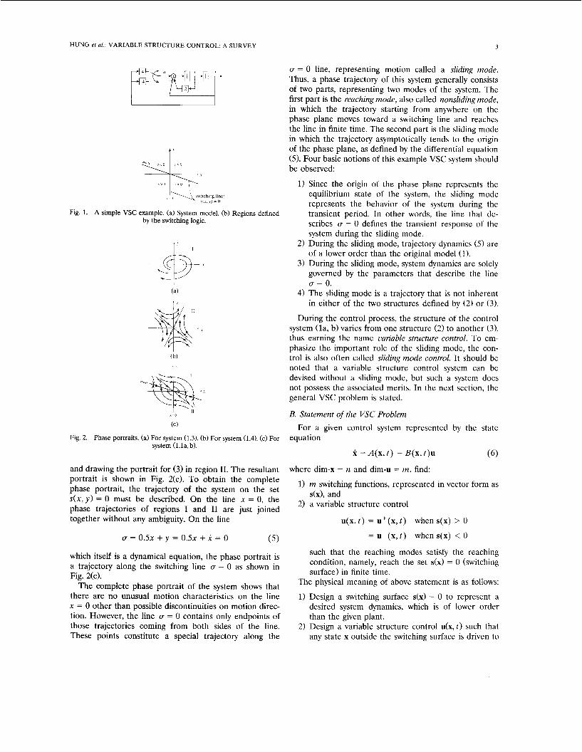
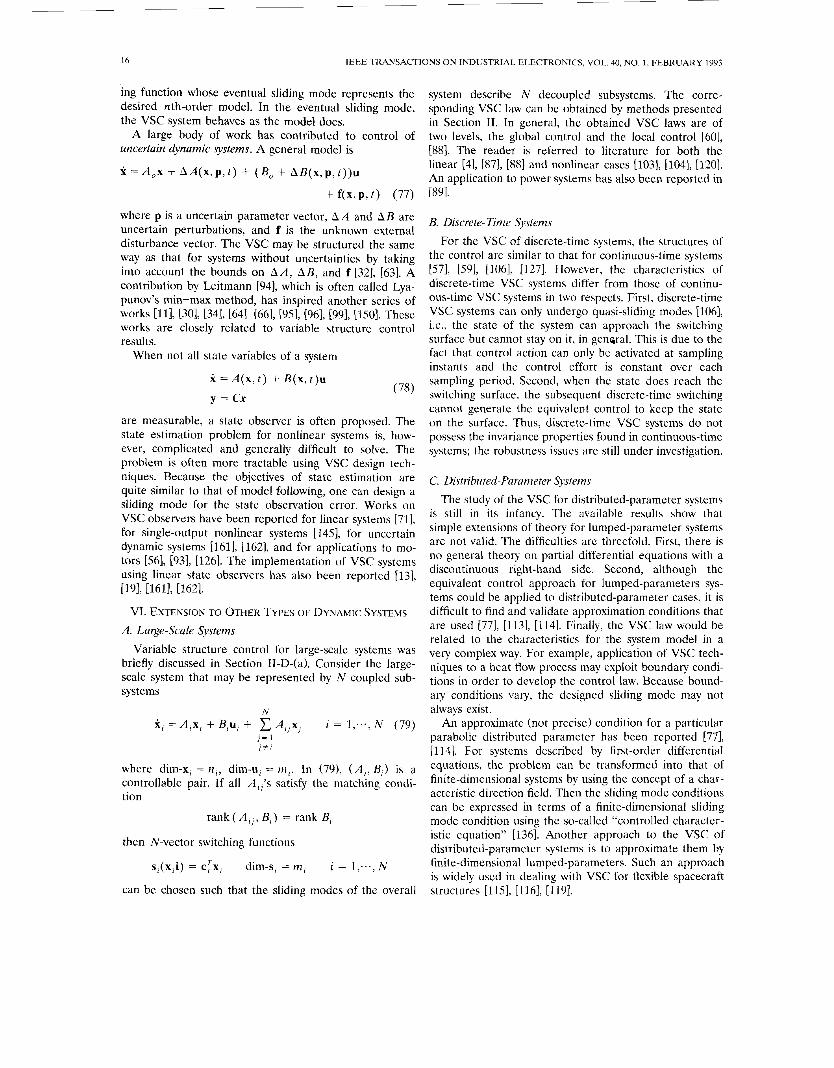
dim-x and d i m 4 stand for dimensions of x and B, A block diagram of the system is shown in Fig. l(a). The variable s(x, y) in (1.14 is the product of two functions
I. INTRODUCTION x = 0 and U = 0 . 5 ~ + y = 0.
ARIABLE structure control (VSC) with sliding mode V control was first proposed and elaborated in the early 1950’s in the Soviet Union by Emelyanov and several coresearchers [43], [79], [ 1541. In their pioneer works, the plant considered was a linear second-order system mod- eled in phase variable form. Since then, VSC has devel- oped into a general design method being examined for a wide spectrum of system types including nonlinear sys- tems, multi-input/multi-output systems, discrete-time models, large-scale and infinite-dimensional systems, and stochastic systems. In addition, the objectives of VSC has been greatly extended from stabilization to other control functions. The most distinguished feature of VSC is its ability to result in very robust control systems; in many cases invariant control systems result. Loosely speaking, the term “invariant” means that the system is completely insensitive to parametric uncertainty and external distur- bances. Today, research and development continue to apply VSC to a wide variety of engineering systems. In this introductory section, the basic notion of VSC and
The functions describe lines dividing the phase plane (xy plane) into regions where s ( x , y ) has different sign as shown in Fig. l(b). As such, the lines (2) are often called switching lines and s(x, y ) is called a switching function. The lines also define the set of points in the phase plane where s ( x , y ) = 0. This set of points is known as the switching su$uce, despite the fact that the set composed of two lines is not a surface in the strict sense. All of these terms are more carefully defined and used later.
The feedback gain q9 is switched according to (lb), i.e., the sign of s ( x , y). Therefore, the system (la, b) is analyti- cally defined in two regions of the phase plane by two different mathematical models: In region I where s(x, y) = x u > 0, model is
x = y y = 2 y - x - (3)
4x = 2 y - 5 x
In region I1 where s ( x , y ) = x u < 0, model is
(4) x = y 3 = 2 y - x + 4x = 2y + 3x.
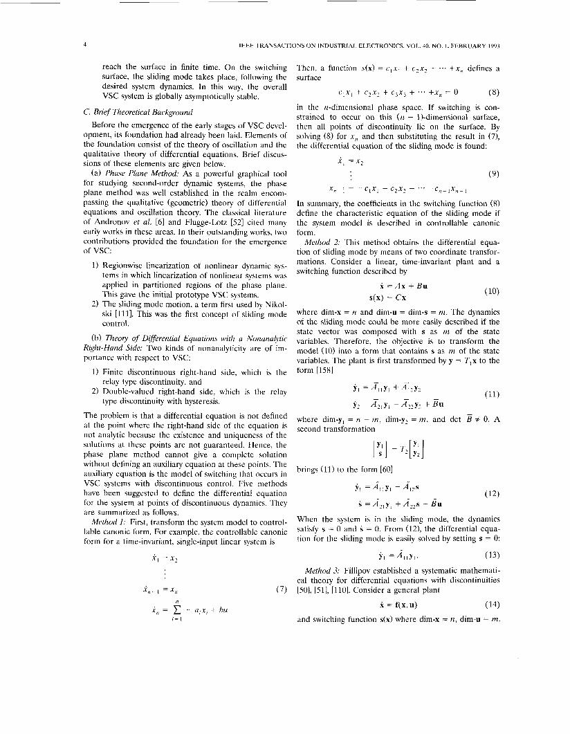
Manuscript received Nov. 26, 1991; revised December 28, 1991, April 30. 1992. and Julv 17. 1992. The phase plane trajectories for (3) and (4) are shown as
J. Y. Hung is’with the Electrical Engineering Department, Auburn port&ts in-Fig. 2(a)”and (b). The equilibrium point of (3) University, Auburn, AL 36849.
Aeronautics and Astronautics, Beijing 100083, China. J. C. Hung is with the Electrical and Computer Engineering Depart-
ment, The University of Tennessee, Knoxville, TN 37996, and is the author to whom correspondence should be addressed.
W. Gao is with The Seventh Research Division, Beijing University of is an unstable focus at the origin. The equilibrium point of (4) is a saddle at the origin; the saddle point is also unstable.
The phase portrait for the system (la, b) is formed by drawing the portrait for (2) in region I of the phase plane IEEE Log Number 9204072.
0278-0046/93$03.00 0 1993 IEEE
HUNG et al.: VARIABLE STRUCTURE CONTROL: A SURVEY 3
I’
Fig. 1. A simple VSC example. (a) System model. (b) Regions defined by the switching logic.
(C)
system (Lla, b). Fig. 2. Phase portraits. (a) For system (1.3). (b) For system (1.4). (c) For
and drawing the portrait for (3) in region 11. The resultant portrait is shown in Fig. 2(c). To obtain the complete phase portrait, the trajectory of the system on the set s ( x , y ) = 0 must be described. On the line x = 0, the phase trajectories of regions I and I1 are just joined together without any ambiguity. On the line
u = O S ~ + y = O S x + i = 0 ( 5 )
which itself is a dynamical equation, the phase portrait is a trajectory along the switching line U = 0 as shown in Fig. 2(c).
The complete phase portrait of the system shows that there are no unusual motion characteristics on the line x = 0 other than possible discontinuities on motion direc- tion. However, the line U = 0 contains only endpoints of those trajectories coming from both sides of the line. These points constitute a special trajectory along the
U = 0 line, representing motion called a sliding mode. Thus, a phase trajectory of this system generally consists of two parts, representing two modes of the system. The first part is the reaching mode, also called nonsliding mode, in which the trajectory starting from anywhere on the phase plane moves toward a switching line and reaches the line in finite time. The second part is the sliding mode in which the trajectory asymptotically tends to the origin of the phase plane, as defined by the differential equation (5). Four basic notions of this example VSC system should be observed:
1) Since the origin of the phase plane represents the equilibrium state of the system, the sliding mode represents the behavior of the system during the transient period. In other words, the line that de- scribes U = 0 defines the transient response of the system during the sliding mode.
2) During the sliding mode, trajectory dynamics ( 5 ) are of a lower order than the original model (1).
3) During the sliding mode, system dynamics are solely governed by the parameters that describe the line U = 0.
4) The sliding mode is a trajectory that is not inherent in either of the two structures defined by (2) or (3).
During the control process, the structure of the control system (la, b) varies from one structure (2) to another (31, thus earning the name variable structure control. To em- phasize the important role of the sliding mode, the con- trol is also often called sliding mode control. It should be noted that a variable structure control system can be devised without a sliding mode, but such a system does not possess the associated merits. In the next section, the general VSC problem is stated.
B. Statement of the VSC Problem
equation For a given control system represented by the state
x = A(x, t ) + B ( x , t ) u (6)
where dim-x = n and dim-u = m , find:
m switching functions, represented in vector form as s(x), and a variable structure control
u(x, t ) = u+(x , t ) when s(x) > 0
= U-(x , t ) when s(x) < 0
such that the reaching modes satisfy the reaching condition, namely, reach the set s(x) = 0 (switching surface) in finite time.
The physical meaning of above statement is as follows:
1) Design a switching surface s(x) = 0 to represent a desired system dynamics, which is of lower order than the given plant.
2) Design a variable structure control u(x, t ) such that any state x outside the switching surface is driven to
4 IEEE TRANSACTIONS O N INDUSTRIAL ELECTRONICS, VOL. 40, NO. I , FEBRUARY 1993
reach the surface in finite time. On the switching surface, the sliding mode takes place, following the desired system dynamics. In this way, the overall VSC system is globally asymptotically stable.
Then, a function s(x) = c l x l + c2x2 + ... +x, defines a surface
(8) C , X l + c2x2 + c3x3 + ... +x, = 0
C. Brief Theoretical Background Before the emergence of the early stages of VSC devel-
opment, its foundation had already been laid. Elements of the foundation consist of the theory of oscillation and the qualitative theory of differential equations. Brief discus- sions of these elements are given below.
(a) Phase Plane Method: As a powerful graphical tool for studying second-order dynamic systems, the phase plane method was well established in the realm encom- passing the qualitative (geometric) theory of differential equations and oscillation theory. The classical literature of Andronov et al. 161 and Flugge-Lotz [52] cited many early works in these areas. In their outstanding works, two contributions provided the foundation for the emergence of vsc:
1) Regionwise linearization of nonlinear dynamic sys- tems in which linearization of nonlinear systems was applied in partitioned regions of the phase plane. This gave the initial prototype VSC systems.
2) The sliding mode motion, a term first used by Nikol- ski [ l l l l . This was the first concept of sliding mode control.
(b) Theory of DiSferential Equations with a Nonanalytic Right-Hand Side: Two kinds of nonanalyticity are of im- portance with respect to VSC:
1) Finite discontinuous right-hand side, which is the
2) Double-valued right-hand side, which is the relay
The problem is that a differential equation is not defined at the point where the right-hand side of the equation is not analytic because the existence and uniqueness of the solutions at these points are not guaranteed. Hence, the phase plane method cannot give a complete solution without defining an auxiliary equation at these points. The auxiliary equation is the model of switching that occurs in VSC systems with discontinuous control. Five methods have been suggested to define the differential equation for the system at points of discontinuous dynamics. They are summarized as follows.
Method 1: First, transform the system model to control- lable canonic form. For example, the controllable canonic form for a time-invariant, single-input linear system is
relay type discontinuity, and
type discontinuity with hysteresis.
x, = x 2
x,-1 =x, , (7)
in the n-dimensional phase space. If switching is con- strained to occur on this ( n - 1)-dimensional surface, then all points of discontinuity lie on the surface. By solving (8) for x , and then substituting the result in (71, the differential equation of the sliding mode is found:
x1 = x 2
(9)
X n p i = - c l x l - c2x2 - *- . - Cnp I X , 1
In summary, the coefficients in the switching function (8) define the characteristic equation of the sliding mode if the system model is described in controllable canonic form.
Method 2: This method obtains the differential equa- tion of sliding mode by means of two coordinate transfor- mations. Consider a linear, time-invariant plant and a switching function described by
X = A x + B u s(x) = c x
where dim-x = n and dim-u = dim-s = m. The dynamics of the sliding mode could be more easily described if the state vector was composed with s as m of the state variables. Therefore, the objective is to transform the model (10) into a form that contains s as m of the state variables. The plant is first transformed by y = Tlx to the form [1581
Y , =A,lYl + & Y 2 -
Y 2 =Az,y , +&y2 + B u
where dim-y, = n - m, dim-y2 = m, and det second transformation
# 0. A
[ ;] = 7$:]
brings (11) to the form I601
Y, = & y , + & S
s = & y l + A22s + B u
When the system is in the sliding mode, the dynamics satisfy s = 0 and S = 0. From (121, the differential equa- tion for the sliding mode is easily solved by setting s = 0:
Y l = A l l y , . (13)
Method 3: Fillipov established a systematic mathemati- cal theory for differential equations with discontinuities [%I, [51], [110]. Consider a general plant
x = f(x,u) (14)
and switching function s(x) where dim-x = n, dim-u = m.

HUNG et al.: VARIABLE STRUCTURE CONTROL: A SURVEY
Given that the system is of variable structure, the system dynamics can be described by two structures
f(x) = f + ( x , u ) when s(x) > 0
= f - ( x , u ) when s(x) < 0. (15)
The system dynamics are not directly defined on s(x) = 0 by (1.15). Instead, Fillipov describes the dynamics on s(x) = 0 as a type of “average” of the two structures in (15)
X f,(x) = pf i+( l - p ) f , , 0 I p I 1 (16)
where
5
f:= l imf+(x,u) and f , = limf-(x,u) s - 0 s - 0
are functions of x. The term p is also a function of x and can be specified in such a way that the “average” dynamic f,(x) is tangent to the surface s(x) = 0. The geometric concept is illustrated in Fig. 3.
Method 4: A fourth method for describing the dynamics of the sliding mode is called the equivalent control ap- proach [153]. Consider the system
x = A(x) + B(x)u (17) with a switching function 4x1. The first step of the equiva- lent control approach is to find the input u,(x) such that the state trajectory stays on the switching surface s(x) = 0. Once the equivalent control input is known, the sliding mode dynamics can be described by substituting u,(x> in (17).
The equivalent control is found by recognizing that S(x> = 0 is a necessary condition for the state trajectory to stay on the switching surface s(x) = 0. Differentiating 4x1 with respect to time along the trajectory of (17) gives
dS d S
d X d X S(x) = --A(x) + --B(x)u = 0. (18)
Solving (18) for U yields the equivalent control
where the existence of the matrix inverse is a necessary condition.
Method 5: The theory of general dynamical system con- cerns a differential equation with its right-hand side being a set-mapping function; the theory is naturally applicable for describing the dynamics of a VSC system on its switching surface [121]. It has been applied to min-max control, which can be considered a special case of VSC 1641, 1661.
In all five methods just described, the objective is to find the differential equation of the sliding mode, which is defined only on the switching surface. Methods 1 and 2 are often more simple to use than the latter three, even though their results do not describe the sliding motion in the original state space because some state transforma- tion is used. Methods 3 and 4 establish the sliding mode
Fig. 3. Fillipov’s construction of the equivalent control.
differential equations in the original state space, but they are seldom used in practice. Method 5 is devoted to establishing a more general theoretical foundation.
D. Brief History of VSC The history of VSC development is marked by three
stages of development-the early stage of VSC, the stage of VSC for multi-input linear systems, and the stage of complete VSC development. Each of them is briefly de- scribed below.
(a) The Early Stage of VSC (1957-1970): VSC systems studied during this period possessed three characteristics. The first characteristic is that each system was modeled by either a high-order, linear differential equation with a single input:
x ( “ ) ( t ) + a , x ( ” - ’ ) ( t ) + .-. +a, . i ( t ) + a, = bu( t ) (20)
or by its equivalent state space model in controllable canonic form (7). The second characteristic is that the switching surface was defined in a special quadratic form:
s(x) = x , ( c l x I + c2x2 + * . * +c,x,). (21)
The third characteristic is that the structure of the control was described by
U = $x, where +!I = a when s(x) > 0
= p when s(x) < 0.
Equations (20)-(22) describe a single-input, linear system with switched feedback gain. Numerous VSC papers were published in this area and their results were well docu- mented [61, [43], [79], [154]. The issues studied in detail included:
(22)
1) Existence of the sliding mode 2) Stability of the sliding mode 3) Systems with time-varying coefficients 4) Effects of system parameter perturbations and out-
5 ) Systems having unmeasurable state variables
The type of systems with the aforementioned three characteristics is quite restrictive. The quadratic nature of the switching function (21) and the structure of the con- trol (22) are sufficient to guarantee a sliding mode re- sponse, but other structures exist that are easier to imple- ment and are more flexible in design. In addition, the controllable canonic representation cannot always reveal the general nature the VSC systems.
(b) The Stage of VSC for Multi-Input Linear Systems (2970-1980): During this period, the theory of VSC for
side disturbances

6 IEEE TRANSACTIONS ON INDUSTRIAL El.ECTRONICS, VOL. 40, NO. I , FEBRUARY 1993
general linear systems was more firmly established; the general system is of the form
x = A x + Bu
where dim-x = n and dim-u = m. an m-dimensional lin- ear vector switching function 4x1 was postulated for the VSC. The control structure for each of the m inputs was described as
(23 1
u,(x) = @,+(x) when s,(x) > 0 (24)
= @,-(x) when s,(x) < 0 i = 1,2;..,m
and every scalar switching function s,(x) was linear in the state variables rather than quadratic. However, the estab- lished VSC theory did not attract much attention for many practical applications. The reason seems to be twofold. First, VSC theory was overshadowed by the popu- lar linear control system design techniques. Second, the important robustness properties of the VSC system were not yet fully recognized or appreciated.
(b) The Present Stage of Adilancing Der>elopment (1980-Present): Since 1980, two developments have greatly enhanced the attention given to VSC systems. The first is the existence of a genral VSC design method for complex systems. The second is a full recognition of the property of perfect robustness of a VSC system with respect to system perturbation and disturbances. As a result, re- search and development of VSC methods have been greatly accelerated, both in theory and in applications. The R & D work may be classified into five categories:
1) Development for different system models. This in- cludes the development of VSC theory for nonlinear systems, discrete-time systems, systems with time delay, stochastic systems, large-scale systems and infinite-dimensional systems.
2) Extension of the objectives of control. The functions of VSC have been extended beyond system stabiliza- tion to include motion following or tracking, model following, model reaching, adaptive and optimal con- trol, and state observation.
3 ) Exploration of additional properties of VSC. Such properties include invariance of the sliding mode to system perturbations, robustness of the reaching or nonsliding mode, and the elimination or reduction of control chatter.
4) Establishment of VSC laws that possess certain characteristics.
5 ) Applications in various engineering problems.
The purpose of this tutorial paper is to present the fundamental theory and main results for the design of VSC systems. The basic notions and a brief history of VSC development have already been presented. More precise definitions and deeper concepts are presented next by considering VSC for linear plants. Concepts dis- cussed are the design of switching surfaces, characteriza- tion of the sliding mode and the reaching or nonsliding mode, control law design, and basic properties of a vari-
able structure system response. The extensions of these concepts to nonlinear systems are then presented. Further extensions of variable structure concepts to other control objectives besides stabilization and regulation are briefly described. Known studies of variable structure control for some special systems are noted. Since application of VSC has been widespread in recent years, some notable contri- butions are listed. Finally, a very extensive list of refer- ences is included. Other survey papers by Utkin [1551- 11571, DeCarlo er al. [35], and a monograph by Gao [601 are also recommended.
11. VSC FOR LINEAR SYSTEMS The discussion in this section concerns the general
linear time-invariant system represented by the state equation
X = A x + B u ( 2 5 ) The state vector x is n-dimensional and the input U is m-dimensional. The m column vectors of the B matrix are designated as b,, for i = 1 to m.
A. Basic Definitions Basic terminology of variable structure systems with
sliding mode are more carefully defined in this section. Definition 1: The structure in a VSC system is governed
by the sign of a vector-valued function s(x), which is defined to be the switching function. A switching function is generally assumed to be m dimensional and linear, i.e.,
s(x) = c x (26) where
S(X) = [s,(x) s?(x) ... S,,,(X)]'' (27)
and
c = [.; .; ... 4 I 7- (28)
Thus
s,(x) = c7'x. (29)
Each scalar switching function s,(x) describes a linear surface s,(x) = 0, which is defined to be ii switching sur- face. The term switching manifold is often used. In addi- tion, the surface can be called a switching hyperplane because the switching function is linear. Notice in the introductory exampled, however, that the set s(x , y) = 0 consisted of two intersecting lines. Such a set is not a manifold in the mathematical sense. Hence, the terms manifold and hyperplane are avoided in the remainder of this paper.
Let x,) be the initial state of the system at the initial time to, x(t) be the state at any time t, and S be a switching surface that includes the origin x = 0.
Definition 2: If, for any xo in S, we have x(t) in S for all t > to, then x(t) is a sliding motion or sliding mode of the system.
Definition 3: If every point in S is an end point, that is, for every point in S there are trajectories reaching it from

HUNG et al.: VARIABLE STRUCTURE CONTROL: A SURVEY
both sides of S, then switching surface S is called a sliding suflace.
Definition 4: The condition under which the state will move toward and reach a sliding surface is called a reaching condition.
From the definitions above, it is shown next that an nth-order system with m inputs will have 2" - 1 switch- ing surfaces.
Let c: be the ith row vector of the matrix C. Then CTX = 0 defines a surface Si of dimension ( n - 1). There are m such surfaces:
Si = {xls,(x) = cTx = 0) i = 1 ,2 ; - . ,m . (30)
Consider the intersection of two surfaces S, and S,, i Z j . Their intersection is an ( n - 2)-dimensional switching surface. The total number of such intersec- tions equals the number of combinations of m sur- faces Si taken two at a time
m ! m ( m - 1)
These switching surfaces are mathematically de- scribed by
S,, = {xls,(x) = cTx = 0 and s,(x) = cTx = 0}
= S , n S , i , j = 1 , 2 ; . . , m , i < j . (31)
A geometric interpretation is shown in Fig. 4. The intersection of the two planes, S, and S,, is the switching surface S,,, which is a line. Further intersections involving multiple surfaces S, can be described in the same manner as in (31). For example, the intersection of three surfaces S,, S,, and s k is a switching surface Sflk of dimension ( n - 3). There are Finally, there is a single switching surface S E of dimension ( n - m), which is the intersection of all surfaces S,, i = 1,2;.., m taken together. SE may be called the eventual switching surface to which all trajectories must eventually reach. The surface is given by
SE = {x~s(x) = CX = 0} = SI n S, n ... n S,. (32)
such surfaces. (: 1
The total number of switching described by 30-32 is 2" - 1. On each of the switching surfaces, there may be a sliding mode that is described by a differential equation of the same dimension as the switching surface. There- fore, it is possible to have a total of 2" - 1 different sliding modes. The sliding mode associated with SE may be called the eventual sliding mode. This way of defining sliding modes was implied in the hierarchical control scheme of Utkin [154]. However, many authors consider only the motion on SE as the sliding motion. Different definitions described here are all useful because there are actually many ways in which a sliding motion can begin.
Fig. 4. Geometric interpretation of various switching surfaces.
These are called switching schemes and are described in more detail in the next section.
B. Switching Schemes As discussed earlier, a system having m inputs can have
m switching functions and up to 2" - 1 sliding surfaces. Although some authors consider dynamics constrained to the eventual sliding surface SE to be the sliding mode, the sliding mode can actually begin in a number of different ways, hereafter referred to as a switching scheme. The number of switching schemes that exist depends on the order of entering different sliding modes.
(a) Fixed-Order Switching Scheme: In this scheme, slid- ing modes take place in a preassigned order as the system state traverses the state space. For example, the state can first move from the initial state xo onto the switching surface S,, which has dimension n - 1. The sliding mode can then move to the surface SI, = (S , n S,), which has dimension n - 2. Sliding moves to progressively lower dimensional sliding surfaces and eventually reaches the surface S E , which has dimension n - m: X, -+ SI - (SI n S,) + (SI n S2 n S,) -+ + S E .
This early scheme has been called the hierarchical VSC scheme [154]. The scheme has several weaknesses, i.e., giving slow and poor transient response in general, result- ing in large magnitude for control effort, and great diffi- culty in its solution.
(b) Free-Order Switching Scheme: Here, the order of sliding modes is not preassigned but follows the natural trajectory on a first-reach-first-switch scheme. The switch- ing takes place depending on the location of the initial state in the state space. This scheme [31], [61] is more plausible than the fixed-order scheme for three reasons. First, using this the solution of VSC is easy to determine. Second, the reaching mode possesses better dynamic char- acteristics. Finally, the resulting control effort is smaller in magnitude so saturation is less likely to occur.
(c) Eventual Sliding Mode Switching Scheme: In this scheme the state is driven from any initial state to the eventual sliding surface S E on which the sliding mode control takes place. There may or may not be sliding modes on other switching surfaces. This scheme is simple in implementation and its control is easy to be made smooth 13.51, [155]. However, the scheme does not guaran- tee good transient characteristics.
(d) Decentralized Switching Scheme: The system is treated as m single-input subsystems, each having a scalar

8 IEEE TRANSACTIONS ON INDUSTRIAL ELECTRONICS, VOL. 40, NO. 1, FEBRUARY 1993
switching function and its associated sliding mode. The subsystems are coupled in general. The combined vector switching function has the form
'('1 = [ s ~ ( x I ) , * * * , sm(xm)l
s , (x , ) = cTx,, i = 1 to m
where x, and c , are n,-dimensional vectors with m
C n, = n.
The scheme is intended for large-scale systems and gives good results [88], [143].
In general, the free-order switching scheme is the best among all schemes. But, for large scale systems, the decentralized switching scheme is prefered.
C. Reaching Conditions and the Reaching Mode The condition under which the state will move toward
and reach a sliding surface is called a reaching condition. The system trajectory under the reaching condition is called the reaching mode or reaching phase. Three ap- proaches for specifying the reaching condition have been proposed.
(a) The Direct Switching Function Approach: The earli- est reaching condition proposed [431, [1541 was
r = l
4, > 0, when s, < 0 S < 0, when s, > 0 i = l;.. , m
or, equivalently,
s,S, < 0 i = l;.., m. (33) This reaching condition is global but does not guarantee a finite reaching time. A similar sufficient condition that is local in nature was proposed by Utkin [155]
lim S, < 0 and lim S, > 0. (34)
It will be shown in Section 11-D-(a) that (33) is very difficult to use for the multiple-input VSC. Even with a simplifying assumption, such as adopting fixed-order switching, the approach remains difficult.
(b) The Lyapunou Function Approach: By choosing the Lyapunov function candidate
s,-0+ s, - 0 ~
V ( x , t ) = sTs (35)
V ( x , t ) < 0 when s # 0. (36)
a global reaching condition is given by [79]
Finite reaching time is guaranteed by modifying (36) to
when s f 0, where E is positive. V ( x , t ) < - E
(37)
Clearly, this approach leads to the eventual sliding mode switch scheme.
(c) The Reaching Law Approach: The crux of the reach- ing law approach is a new method called the reaching law
method. It directly specifies the dynamics of the switching function. Let the dynamics of the switching function be specified by the differential equation
S = -Q sgn(s) - Kf(s) (38)
where gains Q and K are diagonal matrices with positive elements, and
sgn(s) = [sgn (s , ) ... sgn ( s m > l T
'('1 = [ f l ( ~ , ) ... fm(sm>lT.
The scalar functions f, satisfy the condition
s , f , ( s , ) > 0 when s, # 0 , i = 1 to m.
Equation (38) is called the reaching law. Various choices of Q and K specify different rates for s and yield differ- ent structures in the reaching law. Three examples are
1) The constant rate reaching law
S = - Q sgn(s) (39)
2) The constant plus proportional rate reaching law
S = -Qsgn(s) - K s (40)
3) The power rate reaching law
Si = -k,ls,IU sgn (si) o < a < 1 i = 1 to m. (41)
The reaching law approach not only establishes the reach- ing condition but also specifies the dynamic characteristics of the system during the reaching phase [61]. Additional merits of this approach include simplification of the solu- tion for VSC and providing a measure for the reduction of chattering [63]. This approach results in the free-order switching scheme.
D. The Control Law Design of the VSC control law is affected by two
factors: 1) the choice of a sliding mode entering scheme, and 2) whether or not the structure of the control law has been prespecified. In this section, various design ap- proaches are presented. The influence of the sliding mode entering scheme is discussed first. Consider the model represented by (25)-(29) for the following discussion.
(a) Effect of the Switching Scheme: Solutions for the VSC law are straightforward in general, except for the fixed-order sliding mode scheme.
(i) Fixed-order switching scheme: For the fixed-order scheme, the determination of the control U involves the solution of m pairs of inequalities [154, 1741.
> 0, < 0,
when s, < 0 when s, > 0
d S
d X Si = - ( A x + Bu) =
for i = l ; - . ,m. (42)
Let b; be the ith column vector of the B matrix. Develop-

HUNG et al.: VARIABLE STRUCTURE CONTROL: A SURVEY
ing (2.18) and using the notations of (2.1) to (2.5), gives
(43)
Thus (42) consists of 2 m conditional inequalities for 2 m unknowns. The 2 m unknowns are control signals ui(x), i = 1 to m, and each has two values for two different conditions. Solving (42) for them is a very difficult task. The fixed-order switching is helpful in concept but diffi- cult in realization. In addition, its solution tends to result in a very conservative VSC, meaning that the magnitudes of ui(x) are often unnecessarily large. As a result, the scheme is seldom used.
(ii) Free-order switching scheme: For the free-order switching scheme, the control is solved directly from the reaching law specification described by (38)
dS
dX s = - ( A x + Bu) = -Qsgn(s) - K f ( s ) . (44)
The VSC is easily solved from (44) as
U(.) = - ( $ B ) [ $Ax + Qsgn(s) + k f ( s ) ] (45)
(iii) Eventual sliding mode switching scheme: For the eventual sliding mode switching scheme, the control is designed to satisfy a Lyapunov stability criteria
. d dS V = - ( s ~ s ) = 2sTS = 2sT-(Ax + Bu) > 0.
dt dX (46)
The solution for VSC is more involved than that for the free-order switching scheme but is probably easier than that for the fixed-order switching.
(iv) Decentralized switching scheme: For the decen- tralized switching scheme, the VSC controls of all the subsystems are separately designed, Each subsystem con- trol can be obtained independently using any one of the above three approaches. Consider an n th-order large-scale system with m single-input subsystems
m
x, = A , x , + B,u, + ~ , ~ x ~ i = I;.., m. (47) I = 1 /+I
Here dim-x, = n,, and n1 + n2 + ... +n, = n. For the ith subsystem, A, represents dynamics internal to the subsystem, B, is the input vector, and A,, represents coupling to other subsystems. Let there be m switching functions (one associated with each subsystem)
$,(XI) = CTX,.
9
-
- - The overall system sliding mode consists of m indepen- reaching condition s,s, < 0, i = 1 to m, by giving U a
dent sliding modes, each moving on its own sliding surface s,(x,) = 0 such that x, - 0. This scheme is intended for large-scale systems, for which the result is generally good.
(b) Properties of VSC Structures: The design of VSC can proceed with the structure of the control u(x) free or preassigned at the outset. In either case, the objective is to satisfy a reaching condition. In the free structure approach, generally, the control u(x) can be solved by constraining the switching function to any one of the following conditions.
(i) s,S, < o (Direct switching approach)
d (ii) li = - ( s T s ) < o
dt (Lyapunov function approach)
(iii) S, = -q ,sgn(s , ) - k , f , ( s , ) (Reaching law approach).
Additional forms of constraint exist, including
(iv) V = -q - kV V = sTs
(vi) S = -F(s) [49]
The latter forms are seldom used in practice. In some cases, it is convenient to preassign the struc-
ture of the VSC and then determine the values of the controller gains such that the desired reaching law is satisfied. Three popular types of preassigned structures are given here.
1) Relay control: Here, the VSC for each element of the control vector U takes the form of a relay. The relay gain may be either fixed or state dependent
The values of k: and k ; are chosen to satisfy the desired reaching condition.
2) Linear feedback with switched gains: The preassigned structure is
4.1 = @(x)x (49)
where @ = [@,J(x)] is an m x n matrix of state-dependent gains. A popular structure for the gains is
Parameters CY,] and p,, are chosen to satisfy the desired reaching condition. The details of (50) can be varied to suit the problem at hand. For example, in the VSC of model following systems, it is easier to guarantee the
10 IEEE TRANSACTIONS ON INDUSTRIAL ELECTRONICS, VOL. 40, NO. 1, FEBRUARY 1993
preassigned structure such as B = TO B*IT, where B* is an invertible m X m matrix.
u = * x + @ e + O (51) where e = x - xd is the tracking error, xd is the reference state vector, and 0 is a vector. In fact, this approach can be included in the more general technique of the reaching law method and be handled in a much simpler way.
3 ) Augmenting the equivalent control (351: Here, the VSC control takes the form
(52) U = U, + AU
The reduced form of the system model takes the form
x, =A,(x) dim-x, = n - m (56a) x, =A2(x) + B*(x)u dim-x2 = dim-u = m (56b)
Necessary and sufficient conditions for the existence of the reduced form have been established in [lo].
2 ) Controllability Form: Given m inputs, the system model is partitioned into m subsystems, each of which is represented in controllable canonic form [78]. More ex- plicitly, the state vector is in the form
where U, is the equivalent sliding mode control (1.271,
commonly used form for Au is a relay control (48). whereas Au is added to satisfy the reaching condition. A m
x = [x:], dim-x, = n , and E n , = n . (57a) r = l
111. vsc FOR NONLINEAR SYSTEMS
The most general state equation for nonlinear systems Dynamics Of each subsystem are represented in is lable canonic form
i = f(x, U, t ) (53)
where dim-x = n and dim-u = m. The most commonly used special form of (53) describes systems that are linear in the input U. That is,
where
x, = A,x, + a,(x) + p,(x)u i = l,..., m. (57b)
dim-A, = n, X n,
x = A(x, t ) + B(x, t )u . (54) 0
Note that some systems that are not linear in the input U
can still be put in the form of (54) by using an invertible
tem is represented by appending an m-dimensional out- put function
a,(x) = [ 0 1 dim-a, = n,
p,(x) = [ 1 dim-@, = n, X m.
Finally, the overall system dynamics are given by
input transformation. An input-output model of the sys- a,o(x)
0
y = c(x ,u , t ) (55)
to (54). The nonlinear systems considered in this paper PI"(X> will have the same numbers of outputs and inputs. Time- invariant systems are modeled by omitting the variable t in (541455).
Three points are stressed at the outset for nonlinear
systems: A = diag[A,, A2, . . . ,Am]
x = A x + a ( x ) + P(X)U where
1) Basic concepts and the fundamental theory of VSC are similar to those for linear systems.
and staightfonvard. 2) The derivation of a control u(x) is similarly simple a(.) =
=
3) But the analysis of the sliding mode and the search for the corresponding switching function become a more difficult problem.
To study the stability of sliding modes occurring in nonlin- ear systems, various state transformations are used to put the differential equations of the system in one of several possible canonical forms. Reaching laws are generally tailored to take advantage of canonical form characteris- tics.
A. Canonical Forms 1) Reduced Form: The state vector x is partitioned into
x1 and x2, where dim-x, = dim-u = m and dim-x, = n - m. In addition, the input matrix takes the special form
Note that there can be coupling between the m subsys- tems (57b).
3 ) The Input-Output Decoupled Form: Consider a single input/single output (SISO) nonlinear system with out put y = c(x, U ) . Let y'') denote the rth differentiation of y with respect to time. The number of differentiations of the output function y = c(x, U ) required for the input U
to appear explicitly is called the relative degree r of the system. Note that the relative degree of a system cannot be greater than the system order n. This concept of relative degree for a SISO nonlinear system is compatible with the definition of relative degree for linear systems, i.e., the excess of poles over zeros.
Relative degree in a MIMO system is defined in a
HUNG et al.: VARIABLE STRUCTURE CONTROL: A SURVEY 11
similar fashion. For a given output y,, define the relative degree r, to be the smallest integer such that at least one of the inputs appears explicitly in a differentiation. Since there are m outputs in the system, there are m such integers r, . The relative degree is denoted by the set ( r , ; . . , rnl) and the total relatilie degree is defined by r = r1 + ... +r,.
If the total relative degree r equals the system order n, then there are conditions such that the system
X = A ( x ) + B(x)u
Y = c(x) (59)
can be represented as a set of m decoupled higher-order differential equations of the form
mensional switching surface equation
s(x) = S(XI,X2) = 0 (62)
Theoretically, this equation can be solved for x2 in terms of x , in the form of x2 = d x , ) . This is equivalent to expressing the switching function as
s(x) = x2 - w(xl) . (63)
Thus the problem of determining the switch function 4x1 is to find d x , ) such that the sliding mode is asymptoti- cally stable. That is, the system (56a), with x2 = d w , ) is asymptotically stable. In general, it is difficult to find a desired w(x,> unless matrix A , in (56) is of a certain special structure. At any rate, the dimension of x, is n - m, less than that of the original system. Once d x , ) is found, so is s(x). Then the VSC u(x) may be designed using the reaching law method in a way similar to that for linear systems.
)... y‘,‘l-”. . . . ; y n l )...) y $ , - ’ ) ) u ,
i = 1 , ... , m. (60) Using the reaching law (38) in the system (56) yields the
Necessary and sufficient conditions for this transforma- tion have been established in [541, [781. When the total relative degree r < n, then the system can be represented in the normal form, which is presented next.
4) Normal Form: Under certain mild restrictions, a system model (54) that has total relative degree r < n can be transformed into the normal form using differential geometry methods [24], [78]. The state transformation is divided into two groups of scalar functions. The first group of functions z f , , are simply the m output functions y, = c,(x,u) and their derivatives up through order J = r, - 1, where r, is the relative degree of the ith output. The total number of state transformation functions in this first group equals r = r1 + ... +r,,,. The new state vector is completed by finding n - r additional state transforma- tions rlk, k = l;.., n - r , which are independent of each other and the functions zl , , . Since the variables z, , , are associated with the outputs, they can be considered the “external” dynamic variable. The functions rll, are inter- preted as being “internal” variables. The system dynamics are represented in terms of z f , , and 77 = 7,-,IT as follows.
VSC signal
U(.) = - -B*(x) Q sgn(s) + kf(s) ( d Y 2 ] - I (
d S dS +---A,(x) + -A*(x)
d x , dx2
2) VSC for the Controllability Form: In this form, the entire system is decomposed into m subsystems, so it is convenient to use a decentralized sliding mode scheme with decoupled switching functions, such as
s, = cTx, i = l ; . . , m . (65)
The stability of the sliding mode of each subsystem is guaranteed if c; is appropriately chosen. From (57), one sees that x, is a substate vector in the phase variable form and the equations of the subsystem are
i l l = X I 2
Xf2 = x,3
ifn, = a,(x) + plu l i = l; . . ,m.
m
i i , r , = ~i(z, 77) + E ~ i , k ( ~ , V ) U , i =z 1,” . , m k = l
6 = y ( z , q ) dim q = n - r . (61)
In (61), a, and P I , , are scalar-valued functions, and y is a vector-valued nonlinear function. The reduced form, con- trollability canonic form, and the input-output decoupled form are all special cases of the normal form.
B. VSC for Canonical Forms 1) VSC for the Reduced Form: Let the state vector be
partitioned according to (56). Consider a general m-di-
Therefore the switch plane C ~ X , = 0 becomes
+ ~ , ( n z - l p l + C f , , X , = 0. (67) x p ) + x ( r l , - I ) + ... I 1 r l
The VSC can be obtained from (57) and (65) using the reaching law method.
Since each subsystem is in controllable canonic form, the dynamics of the sliding modes are easily determined. Recall that dim-x, On the sliding surface, the n,th component of the state vector x, can be represented in terms of the remaining components by solving (63), s, = 0. Substituting the result in (57b) give the dynamics of the sliding mode s,. The model is in controllable canonic form

12 IEEE TRANSACTIONS ON INDUSTRIAL ELECTRONICS, VOL. 40, NO. 1 , FEBRUARY 1YY3
with order n , - 1, and the characteristic polynomial is specified by the coefficients of the vector c , . Therefore, stability of each sliding mode is guaranteed by choosing the elements of c , to match a desired characteristic equa- tion.
3) VSC for the Input-Output Decoupled Form: This case is very similar to the controllability form case, with the only difference in the meaning of the transformed state variables. Variable structure control issues remain un- changed. The case was studied in [143], [148], where the switching function used took a special form
It should be pointed out that it is very advisable to apply the centralized VSC where a set of subsystem switching function is given by
s , (xI ) = C ~ X , i = 1 to m.
4) VSC for the Normal Form: The known results for variable structure control of a system in normal form (61) assume stability of the zero dynamics. Zero dynamics are dynamics of the system under the condition that outputs and their derivatives equal zero. Therefore, the zero dy- namics are described by the internal dynamic variables with z = 0:
i = Y ( 0 > 7 7 ) . Then, the switching function for a system in the normal form can be chosen as
s, = cTzl i = I;.., m.
Among the literature treating the normal form can be found the case of r = n (total relative degree = system order) 1491, the single-input case [138], and the multiple- input case 1551, [901, [98]. The main issue in this approach is how to guarantee the stability of the zero dynamics ;7 = 7(0,77) and how to relate to the formulation of the output vector function y = c(x).
5 ) VSC for More General Models: As stated earlier, the most general nonlinear model takes the form x = ffx, U, t) . Works in this area exist [131, [141, [135] and deal with some basic concepts, such as the definition of the sliding mode and the possibility of certain approximations in VSC systems. However, many issues remain unexplored.
In summary, the design of a VSC system requires the determination of appropriate switching functions and en- suring stability of the sliding modes. Up to now, these steps are reasonable only when the system is in one of the canonical forms discussed above. This often means that only special cases have been treated. Many problems still remain open and several important issues will be raised in the following discussion about the basic properties of variable structure control.
I v . PROPERTIES OF vsc The complete response of a VSC system consists of
three phases of different modes: 1) the reaching mode, 2)
the sliding mode, and 3) the steady-state mode. The “steady state” of a system is here defined to be the final periodic state of the system, which includes the constant state as a special case. Different forms of steady state include zero-error state, constant offset state, and limit- cycle state.
Since finite delays are inherent in all physical actuators, the sliding and steady-state modes are always accompa- nied by objectionable chattering. The performance of a VSC system is therefore measured by its response charac- teristics, robustness, and severity of chattering.
A. Characteristics of the Reaching Mode To better understand the reaching mode dynamics in a
VSC system, a reaching space representation has been proposed [611. Consider an nth-order system with m in- puts and a switching function s, where dim-s = m. Define an m-dimensional reaching space R , whose coordinates are the m scalar functions s,. Thus, a reaching law dif- ferential equation such as
S = -Qsgn(s) - Kf(s) (68)
represents the dynamics of the reaching mode in the reaching space rather than in the original state space coordinates. Given ffs), (68) can be integrated to yield a solution s(t>, which describes a unique trajectory in R. This trajectory is completely determined by the reaching law’s design and it yields certain important information about the reaching mode. For example, the reaching time T from the initial state s ~ , to the sliding surface s = 0, is more easily determined in reaching space coordinates. Further discussion on reaching space can be found in Gao and Hung in this issue [63].
B. characteristics of the Sliding Mode The behavior of the sliding mode for linear plants has
been discussed in Section 11. One of the main results is that a desired sliding mode dynamics can be achieved by an appropriate design of the switching function. In this section, another characteristic of the sliding mode is con- sidered, namely, robustness or insensitivity to certain modeling errors and disturbances.
Robustness is one of the most distinguishing properties of VSC systems. For a plant represented by either a linear or nonlinear high-order differential equation, the differ- ential equation of the sliding mode can be entirely inde- pendent of effects due to modeling error and external disturbances. Thus, the sliding mode is said to be inruriant (better than just robust) to modeling error and distur- bances. The invariance property requires that certain matching conditions be satisfied; these are examined in more detail next.
Consider a general linear system of the form
x = ( A + AA)x + Bu + f(t) (69)
where A A and f f t ) represent the modeling error- and external disturbance, respectively. If there exist A A and

HUNG ef al.: VARIABLE STRUCTURE CONTROL: A SURVEY 13
6 t ) such that matching conditions [281, [391, [421
A A = B A A and f ( t ) = B A i (70)
are satisfied, then the sliding mode is invariant. The physical meaning of (70) is that all modeling uncertainties and disturbances enter the system through the control channel.
The same result has been extended to nonlinear sys- tems [133]
x = A ( x ) + A A ( x ) + B ( x ) u + f ( x , t ) . (71a)
In fact, for the more general case where B(x) is also perturbed
x = A ( x , t ) + A A ( x , p , t ) + B ( x ) , u
+ A B ( x , P , t)u + f ( x , P , t ) (71b)
where p is an uncertain parameter vector, it has been shown [63] that invariance hold true if the following matching conditions are satisfied
A A ( & P, t ) = B ( x , t ) A A ( x , P , t )
AB(% P , t ) = B ( x , t )A&x, P , f )
f ( x , P , t ) = B ( x , t ) A @ , p , t )
(72)
for certain A A , A B , and i. C. Chattering in Sliding and Steady-State Modes
One of the underlying assumptions in the design and analysis of VSC systems is that the control can be switched from one value to another at will, infinitely fast. In practi- cal systems, however, it is impossible to achieve the high switching control that is necessary to most VSC designs. There are several reasons for this. One cause is the presence of finite time delays for control computation. The second cause is the limitations of physical actuators. An example can be found in dc servomotor control design, where it is often assumed that the plant input is current. Because of winding inductance, it is impossible to switch current at an infinitely fast rate. Since it is impossible to switch the control at infinite rate, chattering always occurs in the sliding and steady-state modes of a VSC system. In the steady state, chattering appears as a high-frequency oscillation about the desired equilibrium point and may also serve as a source to excite the unmodeled high- frequency dynamics of the system [61, [521, [911, 11471. Since chattering is almost always objectionable, significant research effort has been directed at eliminating or reduc- ing its effects. Several methods are described below.
1) The Continuation Approach: In many VSC designs, the control contains terms that are relaylike in nature, as shown in Fig. 6(a). The ideal relay characteristic is practi- cally impossible to implement, so one approach to reduc- ing the chatter is to replace relay control by a saturating, continuous approximation as shown in Fig. 603) [1431, [148]. In state space, a boundary layer around the switch- ing surface is introduced. Within this boundary layer, the control is chosen to be a continuous approximation of the
switching function. An interpretation is that a high-gain control is used near the surface. A consequence of the continuation method is that invariance is lost. The system possesses robustness that is a function of the boundary layer width. Another continuation method [3], [22] re- places a min-max type control
C T X cTx
I C T X l lCTXI + 6 by U = - U = -
where the positive constant 6 makes the control U contin-
The general effects of continuation and the effects of delays in actual implementation of a variable structure control are now described for the four common types of switching characteristics shown in Fig. 5. The reader may find it helpful to consider a simple second-order system and switching surface such as
uous.
(73) .i + a i + px = - k u ( s )
s = x + c x In the phase plane, the sliding surface equation describes a straight line passing through the origin with slope - c .
The ideal relay control (Fig. 5(a)): Here the control takes the form
u(s )=sgn(s ) = +1 when s > 0 = -1 whens < 0
The control is ideal in the sense that it switches instantly at the value s = 0. For this case it is easy to get the exact analytical solution and to sketch the entire phase portrait as shown in Fig. 6(a), from which the following conclu- sions can be illustrated:
An ideal sliding mode exists on the line s = 0, mean- ing there is no chattering. This is because the control can switch infinitely close of the line s = 0. There is no steady-state error. The invariance property holds because the control
The ideal saturation control (Fig. 5(b): The most simple can keep the system on the line s = 0.
saturating control is described by
u ( s ) = s a t ( s ) = +1 when s > L
when Is1 5 L S
= - L
= -1 when s < -L where L > 0 and fL defines the thresholds for entering the boundary layer. Outside the boundary layer, the con- trol is identical to the ideal relay characteristic. Within the boundary layer, however, the control is a high-gain, linear control. As a result, the system will be driven to the boundary layer, but the trajectory cannot not be forced to follow the line s = 0. In the present case, the exact phase portrait of the system can still be obtained as shown in Fig. 6(b), illustrating the following conclusions:
The sliding mode does not exist because the trajec- tory is not forced to stay on the s = 0 surface.

14 IEEE TRANSACTIONS O N INDUSTRIAL ELECTRONICS, VOL. 40, NO. 1, FEBRUARY 1993
+* ‘ I
(C) (4 Fig. 5. Switching functions.
No chattering can occur, since a continuous control is
In the absence of disturbances, there is no steady-state
Invariance property does not exist.
Another type of boundary layer modification that has been proposed [ 1431, [147] involves adaptively adjusting the boundary layer width to match the degree of uncer- tainty in the dynamics of the system.
The Practical relay control (Fig. 5c): A practical relay always exhibits hysteresis, modeled by
used within the boundary layer.
error.
u (s )=hys(s ) = +1 when s > A, or
when S < 0 and Is1 < A
= -1 w h e n s < A , or
when S > 0 and Is1 < A
where 2A > 0 is the amount of the hysteresis in s. The hysteresis characteristic makes it impossible to switch the control on the surface s = 0. Instead, switching occurs on the lines s = f A. The exact solution of the system can be determined with some effort and the phase portrait of the response, Fig. 6(c), illustrates the following general char- acteristics:
A nonideal sliding mode exists, meaning there always
The system has limit cycle behavior in “steady state.”
The origin is not an equilibrium point.
The practical saturation control (Fig. 5(d)): A practical saturation element also exhibits hysteresis. Analysis of a system with such a control is complicated, especially in the case of a nonlinear system. Describing function tech- niques can be useful. Fig. 6(d) shows the phase portrait of the VSC system. Generally speaking:
is chattering in the sliding mode.
It is impossible to eliminate the chatter.
The sliding mode does not exist at all. The VSC system is asymptotically stable in the large,
but has two equilibrium points (points P and P’ in Fig. 6(d)). There is steady-state error. There is no chattering phenomenon. When the slope of the linear part of the saturation function is not sufficiently large, the system ceases to possess any VSC system properties. The invariance characteristics do not exist.
In conclusion, continuation approaches eliminate the high-frequency chattering at the price of losing invari- ance. A high degree of robustness can still be maintained with a small boundary layer width, but significant delays in the control actuator may dictate the need for a “thicker” boundary layer. In the extreme case, large amplitude low-frequency oscillation may result and the system may cease to possess any variable structure behavior. The invariance and robustness properties of the system no longer exist in the latter case. It is interesting to note, in Fig. 6, that in all four cases the VSC systems are stable and their state trajectories are bounded in a strip in the state space. If the width of the strip is sufficiently narrow, the dynamics within the strip may be called the “quasi- sliding mode.” Thus one can consider that the systems shown in b, c, and d of Fig. 7 have quasi-sliding modes.
2) Tuning the Reaching Law Approach: Chattering can be reduced by tuning parameters q, and k , in the reach- ing law
Near the switching surface, s, =: 0, so IS,I = q,. By choos- ing the gain q, small, the momentum of the motion will be reduced as the system trajectory approaches the switching surface. As a result, the amplitude of the chatter will be reduced. However, q, cannot be chosen equal to zero because the reaching time would become infinite; the system fails to be a sliding mode control system. A large value for k , increases the reaching rate when the state is not near the switching surface. Finite reaching time with a zero reaching rate at the switching surface can be achieved using the power rate reaching law (41). By this method, the chattering can practically be suppressed altogether. Simulation results for such control can be found in [631. Other works devoted to the elimination or reduction of chattering exist and can be found in the literature [12], [291, [471, [1021, [1811.
In summary, chattering is a hindrance to the widespread use of VSC in many practical control systems. Elimination or reduction of chattering remains an important and challenging problem.
S, = -4, sgn (s,) - k,s , i = l;.. , m.
v . EXTENSION TO OTHER CONTROL OBJECTIVES
Variable structure control concepts, and more specifi- cally the sliding mode approach, were initially applied to system stabilization or regulator-type problems. The tech- niques have since been extended to many other control issues. The following discussion considers a general sys- tem
where dim-x = n and dim-u = m. X = A(x, t ) + B(x , t ) u (74)

HUNG et al.: VARIABLE STRUCTURE CONTROL: A SURVEY
C Y l y 15
Fig. 6 . Sliding modes and quasi-sliding modes.
The extension of VSC concepts to tracking problems can be found in several references [251, [60], [1601. Here, the objective is to cause the motion x(t) of the system (74) to follow a desired motion xJt) asymptotically.
A related, but different interpretation of the tracking problem is that of model following. That is, the desired motion is that of a reference model (nth order, p inputs):
x, = A , x m + B,r x,(O) = x, (75)
where r is the command or reference input and x, is the initial condition of the system (74). Results in this area can be found in [151, [281, [331, [361, [671, [1301, [1731,[1751. There are also many papers investigating model following systems where some parameters or part of the model is not exactly known. Variable structure control has been used with a variety of other measures to produce adaptive model following systems [31, [51, [91, [lo], [681, [751, [loo], [1451.
In addition to meeting the requirements of following a model output, one may desire the system (74) to behave like the model after finite time. This is called model reaching control. In fact, the most basic VSC can be considered a model reaching control, where the model reached in finite time is the dynamic equation of the sliding mode. This model has dimension p = n - m.
Variable structure control with dynamic feedback com- pensation has recently been proposed [62]. An mth-order state equation that represents the compensator is ap- pended to the original system (74) to give an ( n + m)th- order system
x = A(x, t ) + B(x, t )u (76)
z = Q(x, t ) + W(X, t ) ~ .
One chooses s = s(x, z, t ) to be an m-dimensional switch-
16 IEEE TRANSACTIONS O N INDUSTRIAL ELECTRONICS, VOL. 40, NO. 1, FEBRUARY 1993
ing function whose eventual sliding mode represents the desired nth-order model. In the eventual sliding mode, the VSC system behaves as the model does.
A large body of work has contributed to control of uncertain dynamic systems. A general model is
x = Aox + A A ( x , p , t ) + ( B o + AB(x, p, t ) ) u
+ f ( X , P , t ) (77)
where p is a uncertain parameter vector, AA and A B are uncertain perturbations, and f is the unknown external disturbance vector. The VSC may be structured the same way as that for systems without uncertainties by taking into account the bounds on A A , A B , and f [32], [63]. A contribution by Leitmann [94], which is often called Lya- punov’s min-max method, has inspired another series of works [ l l l , [301, [341, [641-[661, [9Sl, [961, [991, [1501. These works are closely related to variable structure control results.
When not all state variables of a system
X = A(x, t ) + B(x, t)u
y = cx are measurable, a state observer is often proposed. The state estimation problem for nonlinear systems is, how- ever, complicated and generally difficult to solve. The problem is often more tractable using VSC design tech- niques. Because the objectives of state estimation are quite similar to that of model following, one can design a sliding mode for the state observation error. Works on VSC observers have been reported for linear systems [71], for single-output nonlinear systems [ 1451, for uncertain dynamic systems 11611, 11621, and for applications to mo- tors [S61, [931, [1261. The implementation of VSC systems using linear state observers has also been reported [13], [19l, [1611, [1621.
VI. EXTENSION TO OTHER TYPES OF DYNAMIC SYSTEMS
A. Large-scale Systems Variable structure control for large-scale systems was
briefly discussed in Section II-D-(a). Consider the large- scale system that may be represented by N coupled sub- systems
N x, = A,x, + B,u, + A,,x, i = l,..., N (79)
]=1 I + (
where dim-x, = n,, dim-u, = m,. In (79), ( A , , B,) is a controllable pair. If all A,,’s satisfy the matching condi- tion
rank ( A , , , B , ) = rank B,
then N-vector switching functions
s,(x,i) = C T X , dim-s, = m, i = l;.. , N
can be chosen such that the sliding modes of the overall
system describe N decoupled subsystems. The corre- sponding VSC law can be obtained by methods presented in Section 11. In general, the obtained VSC laws are of two levels, the global control and the local control [601, [88]. The reader is referred to literature for both the linear [4], [87], [88] and nonlinear cases [103], [104], [120]. A n application to power systems has also been reported in [891.
B. Discrete- Time Systems For the VSC of discrete-time systems, the structures of
the control are similar to that for continuous-time systems [571, 1591, [1061, [127]. However, the characteristics of discrete-time VSC systems differ from those of continu- ous-time VSC systems in two respects. First, discrete-time VSC systems can only undergo quasi-sliding modes [106], i.e., the state of the system can approach the switching surface but cannot stay on it, in general. This is due to the fact that control action can only be activated at sampling instants and the control effort is constant over each sampling period. Second, when the state does reach the switching surface, the subsequent discrete-time switching cannot generate the equivalent control to keep the state on the surface. Thus, discrete-time VSC systems do not possess the invariance properties found in continuous-time systems; the robustness issues are still under investigation.
C. Distnbuted-Parameter Systems The study of the VSC for distributed-parameter systems
is still in its infancy. The available results show that simple extensions of theory for lumped-parameter systems are not valid. The difficulties are threefold. First, there is no general theory on partial differential equations with a discontinuous right-hand side. Second, although the equivalent control approach for lumped-parameters sys- tems could be applied to distributed-parameter cases, it is difficult to find and validate approximation conditions that are used [77], [1131, [1141. Finally, the VSC law would be related to the characteri5tics for the system model in a very complex way. For example, application of VSC tech- niques to a heat flow process may exploit boundary condi- tions in order to develop the control law. Because bound- ary conditions vary, the designed sliding mode may not always exist.
A n approximate (not precise) condition for a particular parabolic distributed parameter has been reported [771, [114]. For systems described by first-order differential equations, the problem can be transformed into that of finite-dimensional systems by using the concept of a char- acteristic direction field. Then the sliding mode conditions can be expressed in terms of a finite-dimensional sliding mode condition using the so-called “controlled character- istic equation” 11361. Another approach to the VSC of distributed-parameter systems is to approximate them by finite-dimensional lumped-parameters. Such an approach is widely used in dealing with VSC for flexible spacecraft structures L11.51, [I 161, 11191.
HUNG et al.: VARIABLE STRUCTURE CONTROL: A SURVEY 17
D. Time-Delay Systems Other design methods for variable structure control of - To illustrate several features of VSC for systems with manipulators can be found in [11, [7], [26], [38], [70], [74],
[971, [1171, [1631, 11641, [1701, [1711, [1771. time delay, consider
N
k ( t ) = A x ( t ) + A i x ( t - t , ) + B u ( t ) i = 1 (80)
s ( t ) = C x ( t )
where 0 < t , < t , < ... < t,. Note that the trajectory of x from an initial time to can be determined only if the history of x ( t ) for to - t , < t < to is known. So the state space for (80) becomes an n-dimensional functional space whose elements are functions defined on [- t , ,O]. The sliding modes should also be established in the functional space instead of the usual state space. Therefore, two important problems arise. First, one must find a good method to describe the sliding motion, i.e., define the equation of the sliding mode. The second challenge is the design of the matrix C in (80) to yield a stable sliding motion. To the authors' knowledge, these two problems have not been fully solved, but several studies have been reported [761, 1771, 1831.
B. Motor Control Control of electrical motors has been a popular applica-
tion of VSC. The technique has been applied to the control of dc motors, synchronous motors, and induction motors. The following are just a few of many references in the literature [81, [HI, [481, [561, [%I, [681, [721, [821, [861, [931, [123]-[125]. Design of a sliding mode observer for an induction motor has also been done [126].
C. Aircraft Control Variable structure control has been applied to the a
variety of flight problems, including (1) control of lateral motion of an aircraft [166], (2) realization of asymptoti- cally decoupled control of roll angle, angle of attack, and sideslip in the presence of rapid maneuvering [1311, and ( 3 ) flight control 1731, [1081, 11821.
D. Spacecraft Control The VSC of multiaxial spacecraft for large-angle rota-
tional maneuvering has been studied [40], [411, [1591. Ap- plication to spacecraft rotation damping [140] and orienta- tion control [132] has also been reported.
E. Flexible space Structure Control
E. Other Systems It is well k"n that in stochastic control the con-
trollers are usually complex and hard to implement in real time, and the robustness of the control is not clear. Notable exceptions are linear quadratic Guassian (LQG) systems and self-tuning regulators. Therefore, it is tempt-
result in this area have been reported in [181]. Other control systems in which VSC has been studied include learning control [l], neuromorphic networks [ 1491, and
that some VSC results have incorporated state estimators
Studies have been made on the use of VSC for stabi-
space structures [115], [116], [130]. One interesting aspect is that the design of the control laws for the rigid mode control and for the elastic mode stabilization can be
tures are distributed parameter systems, known ap-
ing to the merits Of vsc to stochastic Some lization, regulation, and maneuvering of large flexible
[381, [1491. It has been Pointed Out treated independently [130]. Because large flexible struc-
in the terns using Only Output feedback [''I. It is
A problem is to design vsc 'YS- that many
proaches to study the control involve the use of fi- nite-dimensional truncated models. Hence, many state
interesting problems remain to be studied. variables are not measurable; a state observer has been VII. APPLICATIONS
A. Robot Control The dynamics of an n-link manipulator are usually
modeled by n coupled second-order nonlinear differential equations. Present-day control methods are often based on nonlinear compensations, which require an accurate manipulator model and, hence, load forecasting. Gener- ally these methods are complex and costly in implementa- tion. Fortunately, the dynamic equations can easily be transformed into a nonlinear canonical form and the matching conditions are always satisfied, so a VSC ap- proach to manipulator control appears to be very promis- ing. Studies using ' two-link manipulators have been re- ported in [173], [174], where a hierarchical VSC law was used. The simulation results showed the existence of chattering, a problem that has been studied in greater detail [107], [ 1481, [169]. Applications to parameter identi- fication of robotic systems have been reported 1691, [1451.
used to implement the VSC law [119].
F. Other Applications
variable structure control. Listed as follows are some other known applications of
1) Load frequency control of power systems [171, [271,
2) Servomechanisms [801, [921, [1091, [1761, [1791 3) Pulse-width modulation control [1371, [1391 4) Guidance [22] 5) Process control [841, 1851, [1721 6) Phase-locked loop control [1281 7) Power converters [134] 8) Digital implmentation [2] 9) Remote vehicle control [llSl
Undoubtedly, quite a few other published works of
1891, [1411, [I421
great interest have been missed.
18 IEEE TRANSACTIONS ON INDUSTRIAL ELECTRONICS, VOL. 40, NO. 1, FEBRUARY 1993
VIII. CONCLUSION Having traveled a long history of research and develop-
ment, VSC is well established as a general control method. Its feasibility is increasingly recognized by control profes- sionals, although there are still problems to be investi- gated. VSC is naturally attractive to control engineers because its basic concepts are rather easy to understand and has given satisfactory performance in many practical areas of industrial electronics. More importantly, VSC is applicable to many control systems where there are no other design methods are well-developed. Although con- tributions in the theoretical analysis and design of VSC
[15] -, “The V.S.S. approach to the model reference control of nonminimum phase linear plants,” IEEE Trans Automat. Contr., vol. AC-33, no. 9, pp. 859-863, 1988. -, 1988b, “Asymptotic linearization of uncertain systems by variable structure control,” Syst. Contr. Lett., vol. 10, pp. 111-117, 1988.
[17] N. N. Bengiamin and W. C. Chan, 1982, “Variable structure control of electric power generation,” IEEE Trans. PowerAppara- ius Syst., vol. PAS-101, no. 2, pp. 376-380, 1982. D. Borojevic, H. Naitoh, and F. C. Lee, 1986, “Soft variable-struc- ture based adaptive PI control for dc motor position control,” in Proc. IEEE Industry Applications Society Annual Meeting, pp.
[19] A. G. Bondarev, S. A. Bondarev, N. E. Kostyleva, and V. I. Utkin, “Sliding modes in systems with asymptotic state observers,” Au- tomat. Remote Contr., pp. 679-684, 1985.
[16]
[18]
283-288.
systems will continue to improve, it is of major sign& cance to also conduct experimental research for all kinds Of
undoubtly enhance the confidence of practicing engineers
[20] F. Boudjema, and J. L.-Abatut, 1990, “Sliding mode-A new way to control series resonant converters,” in Proc. I990 IEEE Ind. Electron. Conf., 1990, pp. 938-943. A. M. Breger, A. G. Butkovski, V. A. Kubyshkin, and V. I. Utkin, “Sliding mode control of distribute-parameter entities subjected
problems. The Of such studies [21] I -
to a mobile multi-cycle signal,” Automat. Remote Contr., vol. 41, no. 3, pp. 346-355, 1980. S. D. Brierley and R. Longchamp, “Application of sliding-mode control to air-air interceution uroblem,” IEEE Trans. Aerosp.
considering the use of VSC. This attempts to introduce the [22]
theory, main results, and practical applications of VSC to instrumentation and control professionals of all engineer- ing disciplines. It is hoped that this account will be of help to those who are interested in understanding the powerful
Syst., vol. 26, no. 2, pp. 306-325,’1990. [231 J. A. Burton, and A. S. I. Zinober, “Continuous approximation of
variable structure control,” Int. J . Syst. Sci., vol. 17, no. 6, pp. 875-885, 1986.
capability of VSC and in learning how to design VSC systems. The reference list is intended to contain all
[24] C. I. Byrnes and A. Isidori, “Local stabilization of minimum phase nonlinear systems,” Syst. Contr. Lett., vol. 11, pp. 9-17, 1988.
structure controller. IEEE Int. Conf. Decision & Contr.. ’88. 1988. significant papers published to date’ The authors apolo- [25] S, p, Chan, “Energy saving robust motion control with variable gize for any papers missed.
REFERENCES M. Aicardi, G. Bartolini, and G. Casalino, “Dynamic control of legged locomotion via combined use of learning and variable structure techniques,” in 1990 IEEE Int. Workshop on Intelligent Motion Control, 1990, pp. 703-708. G. M. A y and W. G. Ai, “Digital design of variable structure control systems,” Int. J . Syst. Sci., vol. 21, no. 8, pp. 170*1720. G. Ambrosino, G. Celentano, and E. Garofalo, “Variable struc- ture model reference adaptive control systems,” Int. J . Contr., vol. 39, no. 6, pp. 1339-1349. -, “Decentralized PD controller for tracking control of uncer- tain multivariable systems,” in Proc. IFAC Identification and System Parameter Estimation, 1985, York, UK, 1985, pp.
-, “Adaptive model following control of plants with nonlinear- ities of known form,” IEE Proc., p i . D , vol. 132, no. 1, pp. 11-13, 1985. A. A. Adronov, A. A. Vitt, S. E. Khaikin, Theory of’ Oscillation. Moscow: Fizmatgiz. (in Russian), 1959. E. Bailey and A. Arapostathis, “Simple sliding mode control scheme applied to robot manipulators.” Int. J . Contr., vol. 45, no.
A. Balestrino and A. Landi, “Intelligent variable structure control in electrical drive,” in 1990 IEEE Int. Workshop on Intelligent Motion Control, 1990, pp. 719-722. A. Balestrino, G. De Maria, and L. Sciavicco, “Hyperstable adaptive model following control of nonlinear plants,” Syst. Contr. Lett., vol. 1, no. 4, 232-236, 1982. A. Balestrino,G. De Maria, and A. S. I. Zinober, “Nonlinear adaptive model following control,” Autvmatica, vol. 20, no. 5, pp.
B. R. Barmish, M. Corless, and G. Leitmann, “A new class of stabilizing controllers for uncertain dynamical systems,” S U M J . Contr. Optim., vol. 21, pp. 246-255, 1983. G. Bartolini, “Chattering phenomena in discontinuous control systems,” Int. J . Syst. Sci., vol. 20, no. 12, pp. 2471-2481, 1989. G. Bartolini, and T. Zolezzi, “Control of nonlinear variable structure systems,” J . Mathemat. Anal. Applications, vol. 118, pp. 42-62, 1986. -, “Dynamic output feedback for observable variable-struc- ture control systems,” Syst. Contr. Lett., vol. 7, no. 3, pp. 189-193,
1907-1911.
4, pp. 1197-1209, 1987.
559-568, 1984.
. . pp. 557-581. S. P. Chan and W. B. Gao, “Variable structure model-reaching control strategy for robot manipulators, IEEE Int. Conf. Robotics Automat., Phoenix, AZ, 1989, pp. 1505-1508. W. C. Chan and Y. Y. Hsu, “Automatic generation control of interconnected power systems using variable-structure con- trollers,” Proc. IEE, Pt. D , vol. 128, no. 5, pp. 269-279, 1981. Y. T. Chan, “Perfect model following with a real mode,” JACC, pp. 287-293, 1973. F. J. Chang, S. H. Twu, and S. Chang, “Adaptive chattering alleviation of variable structure systems control,” IEE Proc., Pt. D , vol. 137, no. 1, pp. 31-39, 1990. Y. H. Chan, “On the deterministic performance of uncertain dynamical systems,” Int. J . Contr., vol. 43, no. 5, pp. 1557-1579, 1986. M. Cheng and W. B. Gao, “On the hierarchical switching mode of variable structure systems,” Acta Aeronautica et Astronautica Sinica, Series A , vol. 10, no. 3, pp. 126-133 (in Chinese), 1989. E. Cheres, “Design of min-ma controller with predescribed sliding motion, Int. J . Syst. Sci., vol. 20, no. 12, pp. 2483-2493, 1989. M. Corless, D. P. Goodall, G. Leitmann, and E. P. Ryan, “Model-following controls for a class of uncertain dynamical systems,” in Proc. IFAC Identification and System Parameter Esti- mation, 1985, York, UK, pp. 1895-1899. M. Corless and G. Leitmann, “Continuous state feedback guaran- teeing uniform ultimate boundedness for uncertain dynamic sys- tem,” IEEE Trans. Auto. Contr., vol. AC-26, no. 5, pp. 1139-1144, 1981. R. A. DeCarlo, S. H. Zak, and G. P. Matthews, 1988, “Variable structure control of nonlinear multivariable systems: A tutorial,” Proc. IEEE, vol. 76, no. 3, pp. 212-232, 1988. C. M. Dorling and A. S. 1. Zinober, “Hyperplane design in model-following variable structure control systems,” in Proc. IFAC Symp. Identification and System Parameter Estimation, York, UK, 1985, pp. 1901-1905. -, “Two approaches to hyperplane design in multivariable variable structure control systems,” In f . J . Contr., vol. 44, no. 1, pp. 65-82, 1986. Y. Dote, “Variable structure grasping force controller for manip- ulator hand using fuzzv set theorv,” in Proc. IIth IFAC World .. Y ,
1986. Congress., vol. 8, 1990, pp. 9-13.

HUNG et al .: VARIABLE STRUCTURE CONTROL: A SURVEY 19
[421
[481
B. Drazenovic, “The invariance conditions in variable structure systems,” Automatica, vol. 5 , pp. 287-295, 1969. T. A. W. Dwyer, 111, and H. Sira-Ramirez, “Variable-structure control of spacecraft attitude maneuvers,” 1. Guidance, vol. 1 I, no. 3, pp. 262-270, 1988. T. A. W. Dwyer, 111, H. Sira-Ramirez, S. Monaco, and S. Stornelli, “Variable structure control of globally feedback-decoupled de- formable vehicle maneuvers,” in Proc. 26th Conf. on Decision and Control, 1987, 1281-1287. 0. M. E. El-Ghezawi, A. S. I. Zinober, and S. A. Billings, “Analysis and design of variable structure systems using a geo- metric approach,” Int. J . Contr., vol. 38, no. 3, pp. 657-671, 1983. S. V. Emelyanov, Variable Structure Control Systems. Moscow: Nauka (in Russian), 1967. -, Ed., Theory of Variable Structure Systems. Moscow: Nauka (in Russian), 1970. J. Erschler, F. Robellat, and J. P. Vernhes, “Automation of a hydroelectric power station using variable structure control sys- tems,” Automatica, vol. 10, pp. 31-36, 1974. H. Erzberger, “Analysis and design of model following control systems by state space techniques,” JACC, pp. 572-581, 1968. M. D. Espana, R. S. Ortega, and J. J . Espino, “Variable structure systems with chattering reduction: A microprocessor based de- sign, Automatica, vol. 20, no. l . pp. 133-134, 1984. Feller, P. and U. Benz, “Sliding mode position control of a dc motor, ” in Proc. 10th IFAC World Congress. vol. 3, pp. 333-338, 1987.
[491 R. B. Fernandez, and J. K. Hedrick, “Control of multivariable nonlinear systems by the sliding mode method,” Int. J . Contr., vol. 46, no. 3, pp. 1019-1040, 1987.
[501 A. F. Filippov, “Differential equations with discontinuous right- hand side, Matematicheskii Sbomik, vol. 51, no. 1, pp. 99-128 (in Russian), 1960. -, “Application of theory of differential equations with dis- continuous righthand side to nonlinear control problems,” in Proc. 1st IFAC Congress, Izd. ANSSSR, 1960.
1521 I. Flugge-Lotz, Discontinuous Automatic Control. Princeton, NJ: Princeton University Press, N.I.
[531 D. Franke, “Robust variable structure control of uncertain dis- tributed parameter systems,” in Proc. IFAC Control of Distributed Parameter Systems, Los Angeles, CA, 1986, pp. 263-268.
[54] E. Freund, “The structure of decoupled nonlinear systems,’’ Int. J . Contr., vol. 21, no. 3, pp. 000-000, 1975.
[551 L. C. Fu and T. L. Liao, “Globally stable robust tracking of nonlinear systems using V. S. C. and with an application to a robotic manipulator, IEEE Trans. Automat. Contr., vol. 35, no.
[56] T. Furuhashi, S. Sangwongwanich, and S. Okuma. “A position and velocity sensorless control of brushless dc motors using an adaptive sliding observer,” in Proc. IEEE Ind. Electron. Conf. ’90,
[571 K. Furuta, “Sliding mode control of a discrete system,” Syst. Contr. Lett., vol. 14, pp. 145-152, 1990.
[581 K. Furuta, K. Kosuge, and H. Kobayashi. “Selftuning, sliding mode and adaptive control for direct drive motor, in Proc. IEEE Ind. Electron. Conf., 1988, pp. 459-465.
1591 K. Furuta and M. Morisada, “Tmplementation of sliding mode control by a digital computer,” in Proc. IEEE Ind. Electron. Conf., 1988, pp. 453-458.
[601 W. B. Gao, Fundamentals of Variable Structure Control Theory. Beijing: Press of Science and Technology in China (in Chinese), 1990.
[61] W. B. Gao and M. Cheng, “On the quality control of variable structure systems,” Contr. Decision, vol. 4, no. 4, pp. 1-6, 1989 (in Chinese).
[62] W. B. Gao, M. Cheng, and D. B. Sen, “Variable structure model -reaching control of nonlinear systems,” Contr. Theory and Applications, vol. 7, no. 3, pp. 38-46, (in Chinese).
[63] W. B. Gao and J. C. Hung, “Variable structiire control of nonlinear systems: A new approach,” IEEE Trarrc. Ind. Electron., vol. 40, no. 1, pp. 000-000, Feb. 1993. S. Gutman, “Uncertain dynamical systems-A Lyapunov min- max approach,” IEEE Trans. Automat. Contr., vol. AC-24, no. 3,
S. Gutman and G. Leitmann, “Stabilizing feedback control for dynamical systems with bounded uncertainty,” IEEE Conf. Deci- sion and Control, New York, 1976.
[511
12, pp. 1345-1350, 1990.
pp. 1188-1192.
[64]
pp. 437-443, 1979. [65]
[841
S. Gutman and Z. Palmor, “Properties of min-max controllers in uncertain dynamical systems,” SIAM J . Contr. Optimization, vol. 20, no. 6, pp. 850-861, 1982. L. Guzzella and H. P. Geering, “Model following variable struc- ture control for a class of uncertain mechanical systems, IEEE Conf. Decision and Control, Athens, Greece, pp. 312-316, 1986. F. Harashima, H. Hashimoto, and S. Kondo, “MOSFET con- verter-fed position servo system with sliding mode control,” IEEE Trans. Ind. Electron., vol. IE-32, no. 3, pp. 238-244, 1985. F. Harashima and J. X. Xu, “Parameter identification of two-lin- kage robot manipulator using VSS,” in Preprints of SICE’X6, July 23-26, 1986, Tokyo, Japan, pp. 983-986. H. Hashimoto and F. Harashima, “Variable structure strategy in motion control,” in Proc. 10th IFAC World Congress, vol. 3, 1987,
H. Hashimoto, V. I. Utkin, J. X. Xu, H. Suzuki, and F. Ha- rashima, “VSS observer for linear time varying system, in Proc. IEEE Ind. Electron. Conf. ’90, 1990, pp. 34-39. H. Hashimoto, H. Yamamoto, S. Yanagisawa, and F. Harashima, “Brushless servo motor control using variable structure approach,” IEEE Trans. Industry Applications, vol. 24, no. 1, pp. 160-170, 1988. J. K. Hedrick and S. Gopalswamy, “Nonlinear flight control design via sliding methods,” J . Guid. Contr. Dynamics, vol. 13, no. 5, pp. 850-858, 1990. M. Hiroi, M. Hajo, Y. Hashimoto, Y. Abc, and Y. Dote, “Micro- processor-based decoupled control of manipulators using modi- fied model-following method with sliding mode,” IEEE Trans. Ind. Electron., vol. IE-33, no. 2, pp. 110-113, 1986. L. Hsu and R. R. Costa, “Variable structure model reference adaptive control using only input and output measurements (Part 11,’’ Int. J . Contr., vol. 49, no. 2, pp. 399-416, 1989. Y. M. Hu and Q. J. Zhou, “Variable structure control of control systems with delay,” Acta Automatica Sinica, vol. 17, no. 5 , pp. 587-591, 1991 (in Chinese). -, “Variable structure control of parabolic distributed param- eter systems,” Contr. Theory and Applications, vol. 8, no. 1, pp. 38-42, 1991 (in Chinese). A. Isidori, Nonlinear Control Systems: A n introduction, 1st and 2nd eds., New York: Springer-Verlag, 1985, 1989. Y. Itkis, Control Systems of Variable Structure. New York: Wiley, 1976. -, “Dynamic switching of type I type I1 structure in tracking servosystems,” IEEE Trans. Automat. Contr., vol. AC-28, no. 4, pp. 531-534, 1983. A. Iyer and S. N. Singh, “Sliding mode of control of flexible spacecraft under disturbance torque,” Int. J . Syst. Sri., vol. 21, no. 9, pp. 1755-1771, 1990. D. B. Izosimov and V. I. Utkin, “Sliding mode control of electric motors,” in Proc. IFAC Control Science and Technologv (Xth Triennial World Congr.), Kyoto, Japan, 1981, pp. 2059-2066. E. M. Jafarov, “Analysis and synthesis of multidimensional VSS with delays in sliding modes,” in Proc. 11th IFAC World Congr., vol. 6, 1990, pp. 46-49. J. C. Kantor, “Nonlinear sliding-mode controller and objective function for surge tanks,” h t . J . Contr., vol. 50, no. 5 , pp.
S. Kawata, A. Yamamoto, M. Masubuchi, N. Okabe, and K. Sakata, “Modeling and sliding mode temperature control of a semi-batch polymerization rector implemented at the mixer,” in Proc. 11th IFAC World Congr., vol. 6, 1990, pp. 112-117. M. Kaynak, F. Harashima, and H. Hashimoto, “Variable struc- ture systems theory applied to sub-time optimal position control with an invariant trajectory,” Trans. IEE Japan, vol. 104, no. 3/4,
H. Khurana, S. I. Ahson, and S. S. Lamba, “Variable structure control design for large-scale systems, IEEE Trans. Syst. Man Cybem., vol. SMC-16, no. 4, pp. 573-576, 1986. -, “On stabilization of large-scale control systems using vari- able structure systems theory,” IEEE Trans. Automat. Contr., vol. AC-31, no. 2, pp. 176-178, 1986. A. Kumar, 0. P. Malik, and G. S. Hope, “Discrete variable structure controller for load frequency control of multiarea inter- connected power systems,” in IEE Proc., Pt. C , vol. 134, no. 2, pp.
H. G. Kwatny and H. Kim, “Variable structure regulation of
pp. 57-62.
2025-2047, 1989.
pp. 47-52, 1984.
116-122, 1087.
IEEE TRANSACTIONS ON INDUSTRIAL ELECTRONICS, VOL. 40, NO. 1, FEBRUARY 1993
partially linearizable dynamics,” Syst. Contr. Lett., vol. 15, no. 1,
H. G. Kwatny and T. L. Siu, “Chattering in variable structure feedback systems,” in Proc. IFAC 10th World Corzgr., vol. 8, pp.
H. G. Kwatny and K.-K. D. Young, “The variable structure servomechanism,” Syst. Contr. Lett., vol. 1, no. 3, pp. 184-191, 1981. M. La Cava, P. Muraca, and C. Picardi, “Estimation of the rotor flux components of an induction motor with a sliding mode observer,” IEEE Int. Workshop on Intelligent Motion Control, 1990,
G. Leitmann, “Stabilization of dynamical systems under bounded input disturbances and parameter uncertainty,” in Proc. 2nd Kingston Conf. on Differential Games and Control Theory, New York, 1976. -, “Guaranteed asymptotic stability for some linear systems with bounded uncertainties,” ASME J . Qynamic Systems, Mea- surement and Control, vol. 101, no. 3, pp. 212-216, 1979. -, “On the efficacy of nonlinear control in unccrtain linear systems,” ASME J. Llynamic Systems, Measurement and Control, vol. 103, no. 2, pp. 95-102, 1981. T. P. Leung, Q. J. Zhou, and C. Y. Su, 1991, “An adaptive variable structure model following control design for robot ma- nipulators,” IEEE Trans. Automat. Contr., vol. 36, no. 3. pp.
J. S. Liu and K. Yuan, “On tracking control for affine nonlinear systems by sliding mode,” Syst. Contr. Lett., vol. 13, pp. 439-443, 1989. Y. Liu and W. B. Gao, “A new control method and its robustness for a class of nonlinear systems, J . Optimization Theory and Applications, vol. 58, pp. 117-133, 1988. Y. E. Liu, and V. A. Skormin, “Variable structure adaptive control,” in Proc. IEEE Ind. Electron. Conf. ’88, 1988, pp. 281-286. A. G. Luk‘yanov and V. I. Utkin, “Methods of reducing equations for dynamic systems to a regular form,” Automation and Remote Contr., vol. 43, no. 7, pp. 872-879, 1981. N. S. Luo and C. B. Feng, “A new method for suppressing high-frequency chattering in variable structure control systems,” IFAC Symp. on Nonlinear Control Systems Design, Capri, Italy, 1989. G. P. Matthews and R. A. DeCarlo, “Decentralized variable structure control for a class of nonlinear multi-input multi-output nonlinear systems,” in Proc. 1985 IEEE Conf. on Decision and Control, 1985. -, “Decentralized tracking for a class of interconnected non- linear systems using variable structure control,” Automatica, vol. 24, no. 2, pp. 187-193, 1988. G . P. Matthews, R. A. DeCarlo, P. Hawley and S. Lcfebyrc, “Toward a feasible variable structure control design for a syn- chronous machine connected to an infinite bus,” IEEE Trans. Automat. Contr., vol. AC-31, no. 12, pp. 1159-1163, 1986. D. Milosavljevic, “General conditions for the existence of a quasisliding mode on the switching hyperplane in discrete vari- able structure systems,” Automat. Remote Contr., vol. 46, pp.
R. G. Morgan, and U. Ozguner, “A decentralized variable struc- ture control algorithm for robotic manipulators,” IEEE J. Robotics andAutomation, vol. 1, no. 1, pp. 57-65. 1985. S. K. Mudge and R. J. Patton, “Variable structure control laws for aircraft maneuvers,” IEEE Int. Conf. Control ‘88. 1988. pp.
C. Namuduri and P. C. Sen, “A servo-control system using a self-controlled synchronous motor (SCSM) with sliding mode controller,” Trans. on Industry Applications, vol. IA-23. no. 2. pp. 283-295, 1987. Yu. I. Neymark, “Note of A. F. Filippov’s paper.” in Proc. 1st IFAC Cong., Izd. ANSSSR, 1961 (in Russian). G. N. Nikolski, “On automatic stability of ship on given course,” in Proc. Central Communication Lab.. no. I , pp. 34-75. 1934 (in Russian). Yu. V. Orloov, “Application of Lyapunov method in distributed systems,” Automat. Remote Contr., vol. 44, no. 4, pp. 430-526, 1983. Yu. V. Orlov and V. I. Utkin, “Use of sliding mode in distributed system control problem,” Automat. Remote Contr., vol. 43, no. 9, pp. 1127-1135, 1982.
pp. 67-80, 1990.
307-314, 1987.
pp. 729-735.
347-353, 1991.
307-314, 1985.
564-568.
1231
I241
1251
I261
I271
I281
~ 2 9 1
[ 1301
[1311
[I331
[134]
[I351
[I361
[I381
[1391
-, “Sliding mode control in infinite-dimensional systems,” Automatica, vol. 23, no. 6, pp. 753-757, 1987. H. Oz and 0. Mostofa, “Variable structure control system (VSCS) maneuvering of flexible spacecraft,” in Proc. A M Guidance, Naiigation and Control Conf., Williamsburg, VA, 1986, p. 635. H. Oz and U. Ozguner, “Variable structure system control of flexible spacecraft,” A M / A A S Astrodynamics Conf., Washing- ton, DC. 1984. B. E. Paden and S. S. Sastry, “A calculus for computing Filippov’s differential inclusion with application to the variable structure control of robot manipulators,” IEEE Trans. Circuits Syst., vol. CAS-34, no. I , pp. 73-82, 1987. B. E. Platin, “An application of variable structure systems with sliding mode to a remotely operated vehicle,” in Proc. 11th IFAC World Cong., vol. 8, 1990, pp. 105-111. Z. Q. Qu and W. B. Gao, “State observation and variable structure control of rotational maneuvers of a flexible spacecraft,” Acta Astronautica, vol. 19, no. 8, pp. 657-667, 1989. S. Richter, S. Lefebvre, and R. A. DeCarlo, “Control of a class of nonlinear systems by decentralized control,” IEEE Trans. Au- tomat. Contr., vol. AC-27, no. 2, pp. 492-494, 1982. E. Roxin, “On generalized dynamical systems defined by conti- gent equations,” J . Differential Equations, vol. 1, pp. 188-205, 1965. E. P. Ryan, “A variable structure approach to feedback regula- tion of uncertain dynamical systems,” Int. J . Contr., vol. 38, no. 6,
A. Sabanovic. F. Bilalovic, 0. Music, and F. Mehmedovic, “Squir- rel cage induction motor control system in the sliding mode,” in Proc. IFAC Control Science and Technology 8th Triennial World Congr., Kyoto, Japan, 1981, pp. 2047-2052. A. Sabanovic and D. G. Izosimov, “Application of sliding modes to induction motor control,” IEEE Trans. Industry Applications, vol. IA-17, no. 1, pp. 41-49, 1981. A. Savanovic, D. B. Izosimov, F. Bilalovic, and 0. Music, “Sliding modes in controlled motor drives,” in Proc. IFAC Conf. on Control in Power Electronics and Electrical Driiies, Lausanne, Switzerland, 1983, pp. 133-138. S. Sangwongwanich, S. Doki, T. Yonemoto, and S. Okuma, “Adaptive sliding observers for direct field-oriented control of induction motor,” in Proc. IEEE Ind. Electron. Conf. ’90, 1990, pp. 915-920. S. Z. Sarpturk, Y. Istefanopulos, and 0. Kaynak, “On the stability of discrete-time sliding mode control systems,” IEEE Trans. Au- tomat. Contr., vol. AC-32, no. 10, pp. 930-932, 1987. P. M. Silson and B. A. White, “Application of variable structure control techniques to a digital delay lock loop,” Proc. 25th IEEE Conf. Decision and Control, Athens, Greece, 1986, pp. 1508-1513. -, “On invariance conditions in variable structure controllers,” IEEE In/. Conf. Control ’88, 1988, pp. 725-729. S. K. Singh, “Decentralized variable structure control for tracking in nonlinear systems,” Int. J. Contr., vol. 52, no. 4, pp. 811-831, 1990. S. N. Singh, “Asymptotically decoupled discontinuous control of systems and nonlinear aircraft maneuver,” IEEE Trans. Aerosp. Electron. Syst., vol. AES-25, no. 3, pp. 380-391, 1989. S. N. Singh, and A. Iyer, “Nonlinear Decoupling sliding mode control and attitude control of spacecraft,” IEEE Trans. Aeron. Electron. Syst., vol. AES-25, no. 5, pp. 621-633, 1989. H. Sira-Ramierz, “Differential geometric methods in variable- structure control,” Int. J . Contr., vol. 48, no. 4, pp. 1359-1390, 1988. -, “Sliding-mode control on slow manifolds of dc-to-dc power converters.” In/. J . Contr., vol. 47, no. 5 , pp. 1323-1340, 1988. -, “Sliding regimes in general nonlinear systems-a relative degree approach,” In/. 1. Contr., vol. 50, no. 4, pp. 1487-1506, 1989. -, “Distributed sliding mode control in systems described by quasilinear partial differential equations,” Syst. Contr. Lett., vol. 13, pp. 177-181, 1989. -, “A geometric approach to pulse-width modulated control in nonlinear dynamical systems,” IEEE Trans. Automat. Contr., vol. AC-34, no. 2, pp. 184-187, 1989. ___ , “Structure at infinity, zero dynamics and normal forms of systems undergoing sliding motions,” Int. J . Syst. Sci., vol. 21, no.
H. Sira-Ramirez and P. L. Arenas, “Dynamical discontinuous
pp. 1121-1134, 1983.
4, pp. 665-674, 1990.
HUNG et al.: VARIABLE STRUCTURE CONTROL: A SURVEY 21
feedback control of nonlinear systems,” IEEE Trans. Automat. Contr., vol. AC-35, no. 12, pp. 1373-1378, 1990.
[1401 H. Sira-Ramirez and T. A. W. Dwyer 111, “Variable structure controller design for spacecraft rotation damping,” IEEE Trans. Automat. Contr., vol. AC-32, no. 5, pp. 435-438, 1987.
[1411 A. V. Sivaramakrishnan, M. V. Hariharan, and M. C . Srisailan, “Design of variable structure load-frequency controller using pole assignment technique,” Int. J . Contr., vol. 40, no. 3, pp. 487-498, 1984. -, “Switched control of frequency of interconnected power systems using variable structure,” Int. J . Syst. Sei., vol. 16, no. 11,
[I431 J.-J. E. Slotine, “Sliding Controller design for nonlinear systems,” Int. J . Contr., vol. 40, no. 2, pp. 421-434, 1984.
[1441 -, “The robust control of robot manipulators,” Int. J . Robotics Res., vol. 4, no. 2, pp. 49-64, 1985.
[145] J.-J. E. Slotine and J . A. Coetsee, “Adaptive sliding controller synthesis for nonlinear systems,” Int. J . Contr., vol. 43, no. 6, pp. 1631-1651, 1986.
[1461 J.-J. E. Slotine, J . K. Hedrick, and E. A. Misawa, “On sliding observers for nonlinear systems,” in Proc. American Control Conf., 1986, pp. 1794-1800.
[147] J.-J. E. Slotine and W. Li, Applied Nonlinear Control. Englewood Cliffs, NJ: Prentice-Hall.
11481 J.-J. E. Slotine and S. S. Sastry, “Tracking control of nonlinear systems using sliding surfaces with application to robot manipula- tors, Int. J . Contr., vol. 38, no. 2, pp. 465-492, 1983. R. Swinniarski, “Neuromorphic fuzzy variable structure con- troller,” in Proc. IEEE Ind. Electron. Conf. ’90, 1990, pp.
[150] J. S. Thorp and B. R. Barmish, “On guaranteed stability of uncertain linear systems via nonlinear control,” J . Optimization Theory and Applications, vol. 35, no. 4, pp. 559-579, 1981. S. K. Tso and H. Y. Shum, “Combining model reference adaptive control and variable structure control for improved stabilization of uncertain plants,” in IEEE Int. Workshop on Intelligent Motion Control, pp. 713-718, 1990. V. A. Utkin, “Autonomy in multivariable systems with discontinu- ous control functions,” Aifomatika i Telemekhanika, no. 10, pp. 93-100, 1983 (in Russian). -, “Equations of sliding mode in discontinuous systems, vols. 1, 2,” Automation and Remote Contr., no. 12, pp. 1897-1907, 1971, no. 2, pp. 211-219, 1972. -, Sliding Modes and Their Application in Variable Structure Systems. Moscow: Nauka (in Russian) (also Moscow: Mir, 1978, in English).
[155] -, “Variable btructure systems with sliding mode,” IEEE Trans. Automat. Contr., vol. AC-22, no. 2, pp. 212-222, 1977.
[156] -, “Variable structure systems: Present and future,” Automa- tion and Remote Contr., vol. 44, no. 9, pp. 1105-1120, 1984.
[157] -, “Discontinuous control systems: State of the art in theory and applications,” in Proc. 10th IFAC World Congr. on Automatic Contr., vol. 1, pp. 25-44, 1987.
[I581 V. I. Utkin and K.-K. D. Young, “Methods for constructing discontinuity planes in multidimensional variable structure sys- tems,” Automation and Remote Contr., vol. 39, no. 10, pp. 1466-1470, 1978. S. R. Vadali, “Variable structure control of spacecraft large-angle maneuvers,” J . Guidance Contr. Dynamics, vol. 9, no. 2, pp. 235-239, 1986. G. Verghesc. R. B. Fernandez, and J. K. Hedrick, “Stable, robust tracking by sliding mode control,” Syst. Contr. Lett., vol. 10, pp.
B. Walcott and S. H. Zak, “Laboratory investigation in micropro- cessor-based variable structure control,” IEEE Trans. Educ., vol. E-30, no. 4, pp. 237-243, 1987. -, “Combined observer-controller synthesis for uncertain dy- namical systems with applications,” IEEE Trans. Syst. Man Cy- hem., vol. SMC-18, no. 1, pp. 88-104, 1988. D. Wang and C. T. Leondes, “Robust tracking control of nonlin- ear systems with uncertain dynamics (part I),’’ Int. J . Syst. Sei., vol. 20, no. 12, pp. 2619-2641, 1989. -, “Robust tracking control of nonlinear systems with uncer- tain dynamics (part 2),” Int. J . Syst. Sei., vol. 20, no. 12. pp. 2643-2661, 1989. B. A. White. “Range-space dynamics of scalar-variable structure control systems,’‘ IEE Proc. Pt. D , vol. 133, no. 1, pp. 35-41,
[1421
pp. 1409-1424, 1985.
[1491
1221- 1226.
[151]
[I521
[153]
[154]
[159]
[160]
27-34, 1988. [161]
[162]
[ 1631
[164]
[165]
1986. [166] B. A. White, R. J. Patton, S. Mudge, and P. P. A s h , “Reduced
order variable structure control of the lateral motion of an aircraft,” in Proc. 25th Conf. Decision and Contr., Athens, Greece,
B. A. White and P. M. G. Silson, “Reachability in variable structure control systems,” IEE Proc., Pt. D , vol. 131, no. 3, pp.
[168] X.-H. Xu, Y.-H. Wu, and W.-H. Huang, “Variable structure control approach of decentralized model-reference adaptive sys- tems,” IEE Proc., Pt. D, vol. 137, no. 5, pp. 302-306, 1990.
[169] K. S. Yeung and Y. P. Chen, “A new controller design for manipulators using the theory of variable structure systems,” IEEE Trans. Auto. Contr., vol. AC-33, no. 2, pp. 200-206, 1988. -, “Regulation of a one-link flexible robot arm using sliding mode technique,” Int. J . Contr., vol. 49, no. 6, pp. 1965-1978, 1989. -, “Sliding-mode controller design of a single-link flexible manipulator under gravity,” Int. J . Contr., vol. 52, no. 1, pp.
[172] G. E. Young and S. Rao, “Robust sliding-mode control of a nonlinear process with uncertainty and delay,” J. Dynamic Syst., Measur. Contr., vol. 109, pp. 203-208, 1987. K.-K. D. Young, “Asymptotic stability of model reference systems with variable structure control,” IEEE Trans. Automat. Contr., vol. AC-22, no. 4, pp. 279-281, 1977. -, “Controller design for a manipulator using theory of vari- able structure systems,” IEEE Trans. Syst. Man Cybem., vol. SMC-8, no. 2, pp. 101-109, 1978. -, “Design of variable structure model-following control sys- tems,” IEEE Trans. Automat. Contr., vol. AC-23, no. 6, pp. 1079-1085, 1978. -, “A compensator-based approach to variable structure ser- vomechanism design,” in Proc. IEEE Conf: Decision Contr., San Antonio, TX, 1983, pp. 1121-1124. -, “A variable structure model following control design for robotics applications,” in Proc. IEEE Int. Conf. on Robotics and Automation, San Francisco, CA, 1986, pp. 540-545. K.-K. D. Young, P. V. Kokotovic, and V. L. Utkin, “A singular perturbation analysis of high-gain feedback systems,” IEEE Trans. Automat. Contr., vol. AC-22, no. 6, pp. 931-938, 1977.
[179] K.-K. D. Young and H. G . Kwatny, “Variable structure ser- vomechanism design and its application to overspeed protection control,” Automatica, vol. 18, no. 4, pp. 385-400, 1982. S. H. Zak, J . D. Brehove, and M. J . Corless, “Control of uncertain systems with unmodeled actuator and sensor dynamics and in- complete state information,” IEEE Trans. Syst. Man Cybem., vol. SMC-19, no. 2, pp. 241-257, 1989.
[181] A. S. I. Zinober, 0. M. E. El-Ghezawi, and S. A. Billings, “Multivariable variable-structure adaptive model following con- trol systems,” IEE Proc., Pi. D , vol. 129, no. 1, pp. 6-12, 1982.
[182] A. S. I. Zinober, M. K. Yew, and R. J . Patton, “Variable structure model-following control of flight dynamics,” IEEE Int. Conf. Control ’88, 1988, pp. 702-712.
1986, pp. 322-327. [167]
85-91, 1984.
[170]
[171]
101-117, 1990.
[173]
[174]
[I 751
[176]
[177]
[178]
[180]
John Y. Hung (S’79-M’SO) received the B.S. degree from the University of Tennessee, Knoxville, the M.S.E. degree from Princeton University, and the Ph.D. from the University of Illinois, Urbana, all in electrical engineering, in 1979, 1981, and 1989, respectively.
From 1981 to 1985 he was a design engineer for Johnson Controls Inc., Milwaukee, WI, where he designed microprocessor-based hardware and software used in the control of commercial heat- ing, ventilation, and air conditioning systems.
Since 1989, he has been an Assistant Professor in the Department of Electrical Engineering at Auburn University, Alabama. His current research interests are in nonlinear control, communications, and signal processing. Application interests include the control of robots and motor
22 IEEE TRANSACTIONS ON INDUSTRIAL ELECTRONICS, VOL. 40, NO. 1, FEBRUARY 1993
drives, electromagnetic systems, and the analysis of power electronic circuits.
Dr. Hung is a member of Eta Kappa Nu and Tau Beta Pi.
Weibing Gao (SM’90) received the B.S. in Aero- nautics degree from the Northwest Institute of Technology, People’s Republic of China, in 1948.
He has been a faculty member in Northwest Institute of Technology and Qinghua University. Currently, he is associated with the Beijing Uni- versity of Aeronautics and Astronautics where he is a Professor in the System and Control Division, and a Vice-Dean of the Graduate School of the University. He is a specialist in control systems with his main interests in non-
linear control systems, robot control, variable structure control, large- scale systems, dynamics and control of flexible structure, intelligent motion control, and robust control. He has authored three books-Intro- duction to Nonlinear Control Systems, Fundamentals of Variable Structure Control Systems, and Stability of Motions (all in Chinese). He has also authored or coauthored well over 200 technical papers.
Professor Gao is a member of the Chinese Academy of Science. He is an Associate Editor of the IEEE TRANSACTIONS ON INDUSTRIAL ELEC- TRONICS, Editor in Chief of the Chinese Joumal of Control and Decision,
and a member of the editorial committee of the Chinese Joumal of Automation. He also holds several other leadership positions in academic organizations concerning systems and control in China.
James C. Hung (S’55-M’60-SM’62-F‘84) re- ceive the B.S. degree in electrical engineering from the National Taiwan University, Taiwan. China, in 1953, and the M.E.E. and Sc.D. de- grees from New York University in 1956 and 1961, respectively.
From 1954 to 1961 he was associated with the Department of Electrical Engineering at New York University. He joined the University of Tennessee, Knoxville, as an Assistant Professor in 1961. and became Associate Professor and
Professor in 1962 and 1965, respectively. He was named Distinguished Professor of the University of Tennessee, Knoxville, in 1984, in the Department of Electrical and Computer Engineering. He is a specialist in system analysis, system design, and data processing, with applications to navigation, guidance, and control.
Dr. Hung is a member of Sigma Xi, Tau Beta Pi, Eta Kappa Nu, and Phi Kappa Phi. He is a Registered Professional Engineer in the State of Tennessee.

![Survey Paper Variable Structure Systems with Sliding Modeseusai/BOSIO/[1] - Utkin-Survey-TAC-1977.pdf · where his activities have ranged from missile guidance error analysis,](https://img.pdfslide.us/doc/110x75/5aa69f567f8b9ae7438ef846/survey-paper-variable-structure-systems-with-sliding-eusaibosio1-utkin-survey-tac-1977pdfwhere.jpg)