Embed Size (px)
Citation preview

loo
ks
good, performs bette
r
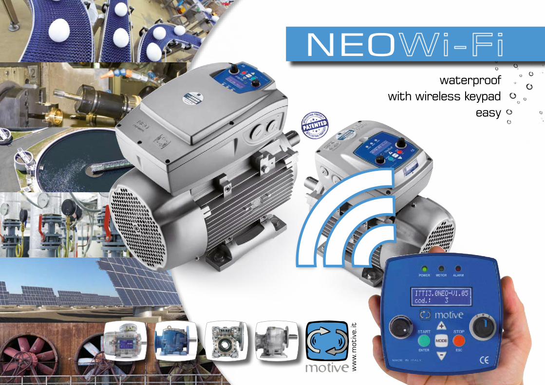
VArIAble speed drIVe Neo-WIfI
neo
ww
w.m
otiv
e.it
waterproof with wireless keypad
easy
index
Technical specifications pag. 2-3
Examples pag. 4Working conditons pag. 5
Working conditons pag. 6-7electrical assemblyConnection of the external devices pag. 14 pag. 15
Motors that can be connected pag. 8Mechanical assembly pag. 9Dimensions
electrical assemblyConnection of the external devices pag. 16Programming pag. 17Keypad-inverter communication
Mechanical assembly Dimensions pag. 10Motor assembly pag. 11
Mechanical assemblyKeypad assembly pag. 12BLOCK pag. 13
Programming Advanced functions menu pag. 20-21
Programming alarms pag. 22Declaration of conformity pag. 23Event analysis
Programming Keypad buttons and led pag. 18Functions menu pag. 19
Terms of sale and guarantee pag. 24
TEChniCAL spECiFiCATiOns
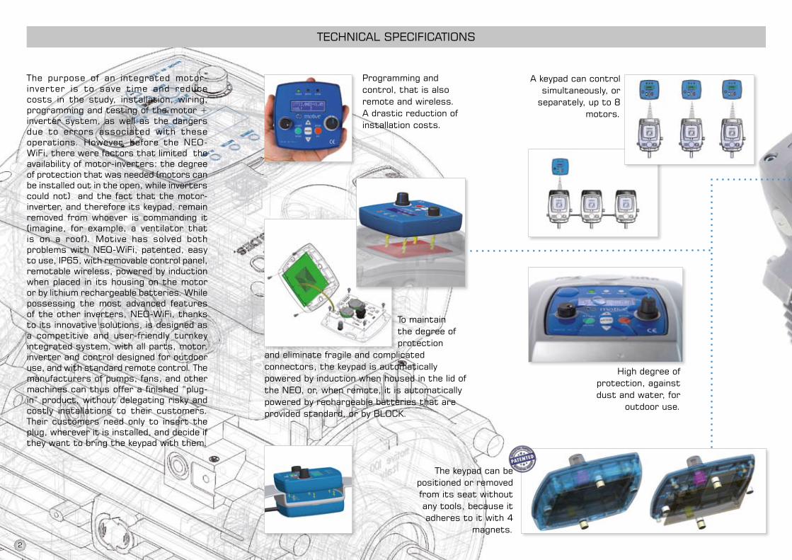
The purpose of an integrated motor-inverter is to save time and reduce costs in the study, installation, wiring, programming and testing of the motor + inverter system, as well as the dangers due to errors associated with these operations. however, before the nEO-WiFi, there were factors that limited the availability of motor-inverters: the degree of protection that was needed (motors can be installed out in the open, while inverters could not) and the fact that the motor-inverter, and therefore its keypad, remain removed from whoever is commanding it (imagine, for example, a ventilator that is on a roof). Motive has solved both problems with nEO-WiFi, patented, easy to use, ip65, with removable control panel, remotable wireless, powered by induction when placed in its housing on the motor or by lithium rechargeable batteries. While possessing the most advanced features of the other inverters, nEO-WiFi, thanks to its innovative solutions, is designed as a competitive and user-friendly turnkey integrated system, with all parts, motor, inverter and control designed for outdoor use, and with standard remote control. The manufacturers of pumps, fans, and other machines can thus offer a finished “plug-in” product, without delegating risky and costly installations to their customers. Their customers need only to insert the plug, wherever it is installed, and decide if they want to bring the keypad with them.
programming and control, that is also remote and wireless. A drastic reduction of installation costs.
high degree of protection, against dust and water, for
outdoor use.
To maintain the degree of protection
and eliminate fragile and complicatedconnectors, the keypad is automaticallypowered by induction when housed in the lid of the nEO, or, when remote, it is automatically powered by rechargeable batteries that are provided standard, or by BLOCK.
A keypad can control simultaneously, or
separately, up to 8 motors.
The keypad can be positioned or removed from its seat without any tools, because it adheres to it with 4
magnets.
2

Rotatable keypad.
The keypad is availa-ble in two versions:
with or without ana-logue controls.
The keypad can be fixed to a metal wall with its magnets or to a concrete wall using inserts.
Any nEO can be fixed to a wide range of motors of different power and size.
Equipped with pC interface sW for
event analysis.
incorporated filters of nEO-Wifi-11 make it suitable for industrial environment
EMC. nEO-WiFi-3 EMC is compatible not just with industrial environment, but also light industrial, commercial and residential environments.
3

examples
Adjusting the flow/pressure/force of a pump, a hydraulic power unit, an oil-hydraulic actuator, a compressor, an extraction fan, a ventilator, etc is normally done through shutters or valves. if we have a choke device of this kind, it means we have chosen not to use a variable speed drive (inverter). in this case, the disadvantages are numerous: inability to program ramping up or stopping; nor to synchronize multiple devices; fewer opportunities for interaction with other machines and controls (such as a pressure transducer), less access to controls, more noise, greater peak currents; shorter life of the motor and of the mechanical parts of the system; and above all the absence of energy savings. it is like controlling the speed of a car just by using the brake. An inverter also simplifies the installation because a system with direct or star-delta type starting often involves the use of suitably oversized power contactors to counter the high electric arcing caused by the overcurrent normally associated with these starting systems. in addition, protection systems for the motor via circuit breakers should always be provided. so: shutter/valve + cabinet + knife switch + motor control relay + motor overload protection automatic switch could be saved with a variable speed drive. Let’s add that in certain applications, just the cost of the choke (think for example of the proportional valve of a hydraulic power unit) exceeds that of an inverter. so why not just use inverters? Essentially for the ease of assembly (assumed) with respect to an electronic device to be wired up and programmed, the reduced size, the degree of protection from dust and liquids and the ease of use, the difficulty of integrating in
the system the inverter with its cabinet, the accessibility of the controls. sometimes also the cost of the inverter can be considerable, especially when it is added to that of a cabinet and cables.With nEO-WiFi these reasons are no longer valid. There remain only the advantages of the inverter. in fact:• NEO-WiFiisamotor-inverterandassuch
cancels the need for cables and cabinets, the study, the installation, the wiring, and the testing of the motor+inverter system, as well as the risks associated with possible errors.
• Notrequiringcablesandcabinets,andbeingan integral part of the motor, it does not take up space
• Programming is easier thanusing the TVremote control
• ThekeypadoftheNEO-WiFi isremovable,can operate remotely over wireless and can be placed up to 20 meters away. no wiring, no cables. it does not need wiring because it is supplied by induction when placed in its housing on the motor or in the "BLOCK" device, or fed by rechargeable lithium batteries. imagine for instance the advantage of installing a ceiling fan with this drive and controlling it from wherever you want without any installation cost
• Evenachildknowshowtouseadevicewitha red button, a green one, a left-zero-right switch and a control knob
• NEO-WiFiisIP65.ItskeypadisIP67
4
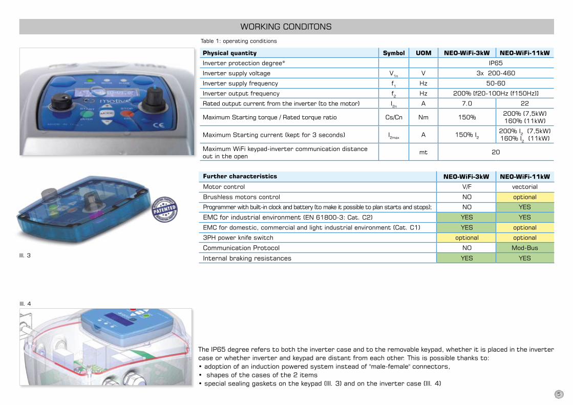
neO-WiFi-3kW neO-WiFi-11kW
ip65
V1n V 3x 200-460
f1 hz 50-60
f2 hz 200% [f20-100hz (f150hz)]
i2n A 7.0 22
nm 150% 200% (7,5kW)160% (11kW)
i2max A 150% i2200% i2 (7,5kW) 160% i2 (11kW)
mt 20
neO-WiFi-3kW neO-WiFi-11kW
WORKinG COnDiTOns
Physical quantity Symbol UOM
inverter protection degree*
inverter supply voltage
inverter supply frequency
inverter output frequency
Rated output current from the inverter (to the motor)
Maximum starting torque / Rated torque ratio Cs/Cn
Maximum starting current (kept for 3 seconds)
Maximum WiFi keypad-inverter communication distance out in the open
The ip65 degree refers to both the inverter case and to the removable keypad, whether it is placed in the inverter case or whether inverter and keypad are distant from each other. This is possible thanks to:•adoptionofaninductionpoweredsysteminsteadof"male-female"connectors,•shapesofthecasesofthe2items•specialsealinggasketsonthekeypad(Ill.3)andontheinvertercase(Ill.4)
Table 1: operating conditions
ill. 3
ill. 4
Further characteristics
Motor control V/F vectorial
Brushless motors control nO optional
programmer with built-in clock and battery (to make it possible to plan starts and stops); nO YEs
EMC for industrial environment (En 61800-3: Cat. C2) YEs YEs
EMC for domestic, commercial and light industrial environment (Cat. C1) YEs optional
3ph power knife switch optional optional
Communication protocol nO Mod-Bus
internal braking resistances YEs YEs
5

have you ever had a sporadic and inexplicable malfunction of electrical/ electronic devices? For example, an automatic gate, a computer, a pLC, a circuit breaker ... if you didn't find the fault, it was probably due to the electromagnetic compatibility of the device (not sufficiently immune to e lectr ica l /e lectromagnet ic interference received from the power line or radiated in the air) or to that of other equipment that showed no malfunction but was disturbing your device. Electromagnetic compatibility is a requirement prescribed by law and by the need to guarantee the
operation of all electrical/electronic equipment, on the basis of which it must in practice:• limit below precise thresholds emissions of electrical and
electromagnetic interference which can affect the operation of other devices, whether the interference is radiated through the air or conducted in the power line or in the earth return circuits;
• beimmunetoaseriesofconductedandradiatedinterferencethat may be present in the environment in which it is intended to operate.
so the regulations define these two environments:
DOMEsTiC, COMMERCiAL ANDLIGHTINDUSTRIALENVIRONMENT
(ref. En 50081-1, para 5)
INDUSTRIALENVIRONMENT
(ref. En 50081-2, para 5)
This concerns residential, commercial and light industrial locations, both internal and external. Locations with a power supply from 50 to 1000Vprovided direct from the public network are considered residential, commercial or light industrial locations.
industrial environments are characterized by the existence of one or more of the following conditions: • presenceofindustrial,scientificormedical
equipment• inductiveandcapacitiveloadsarefrequently
switched • currentsandassociatedmagneticfieldsare
high
it is important therefore not only to protect the operation of the inverter (variable speed drive), but also to protect all the other devices from it. Electromagnetic compatibility is therefore the result of coexistence without reciprocal interference of devices in the same environment.
in an industrial environment, the immunity level must be higher compared to the others, but on the other hand, in a residential, commercial or light industrial environment, it is necessary to limit potential interference emissions more than in the industrial environment.
WORKinG COnDiTOns
neO-WiFi eMC = Secure operation
6
WORKinG COnDiTOns
neO-WiFi eMC = Secure operation
2. the installation of additional anti-interference filters To make a compatible inverter, the manufacturer will have to allow for additional
costs, such as the insertion of components, shielding and filters. To offer a price apparently more attractive, a frequent trick is to not incorporate in the inverter everything you need and to resolve the problem by requiring you in the instruction manual to buy anti-interference filters separately and install them. A careless buyer may then fool themselves that they have saved, only to find out later, on reading the manual, that if he/she wants to comply with applicable laws and avoid problems operating the inverter or other devices in the same environment, he/she will have to incur additional costs for materials and instal-lation.
Another recurrent story is installing inverters suitable only for industrial en-vironments, even if the company has power supplied directly from the mains, putting at risk the operation of other devices. This leaves the problem to the end user to understand why an automatic gate, a computer, a pLC, a protective circuit breaker or other electronic devices in the same environment will begin to have problems of malfunction which will not be confirmed and resolved by the suppliers of the inverter.
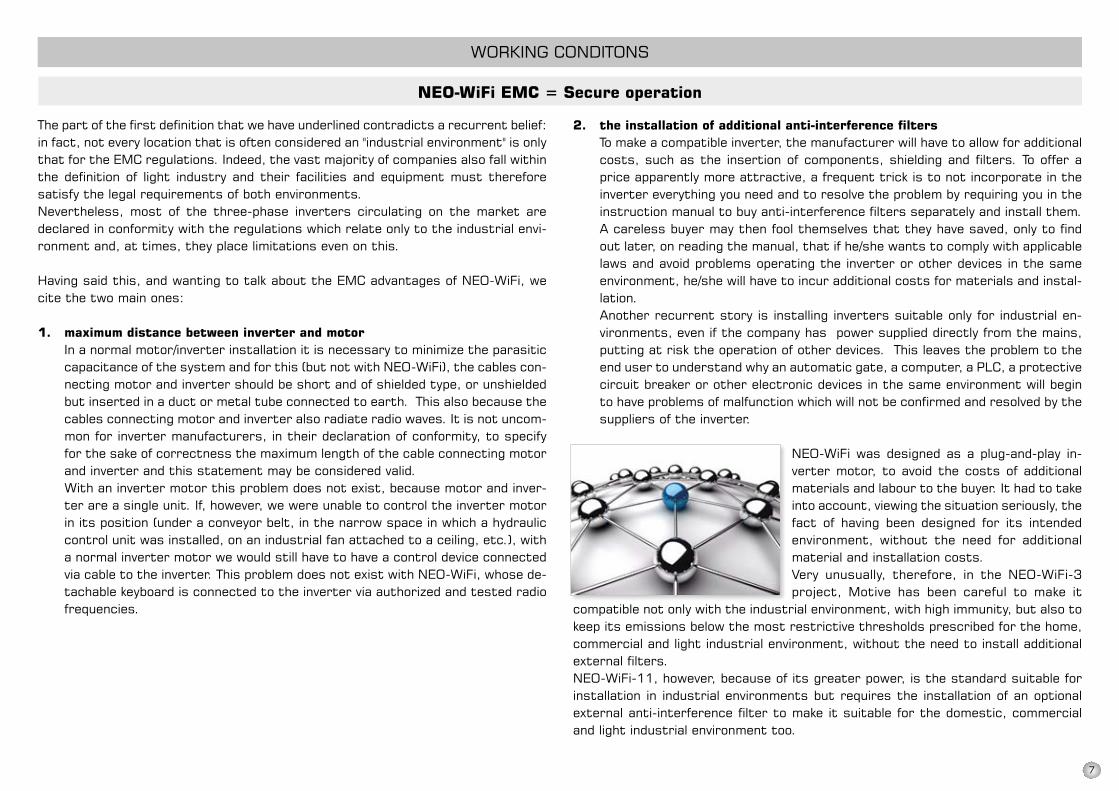
nEO-WiFi was designed as a plug-and-play in-verter motor, to avoid the costs of additional materials and labour to the buyer. it had to take into account, viewing the situation seriously, the fact of having been designed for its intended environment, without the need for additional material and installation costs.Very unusually, therefore, in the NEO-WiFi-3project, Motive has been careful to make it
compatible not only with the industrial environment, with high immunity, but also to keep its emissions below the most restrictive thresholds prescribed for the home, commercial and light industrial environment, without the need to install additional external filters. nEO-WiFi-11, however, because of its greater power, is the standard suitable for installation in industrial environments but requires the installation of an optional external anti-interference filter to make it suitable for the domestic, commercial and light industrial environment too.
The part of the first definition that we have underlined contradicts a recurrent belief: in fact, not every location that is often considered an "industrial environment" is only that for the EMC regulations. indeed, the vast majority of companies also fall within the definition of light industry and their facilities and equipment must therefore satisfy the legal requirements of both environments.nevertheless, most of the three-phase inverters circulating on the market are declared in conformity with the regulations which relate only to the industrial envi-ronment and, at times, they place limitations even on this.
having said this, and wanting to talk about the EMC advantages of nEO-WiFi, we cite the two main ones:
1. maximum distance between inverter and motor in a normal motor/inverter installation it is necessary to minimize the parasitic
capacitance of the system and for this (but not with nEO-WiFi), the cables con-necting motor and inverter should be short and of shielded type, or unshielded but inserted in a duct or metal tube connected to earth. This also because the cables connecting motor and inverter also radiate radio waves. it is not uncom-mon for inverter manufacturers, in their declaration of conformity, to specify for the sake of correctness the maximum length of the cable connecting motor and inverter and this statement may be considered valid.
With an inverter motor this problem does not exist, because motor and inver-ter are a single unit. if, however, we were unable to control the inverter motor in its position (under a conveyor belt, in the narrow space in which a hydraulic control unit was installed, on an industrial fan attached to a ceiling, etc.), with a normal inverter motor we would still have to have a control device connected via cable to the inverter. This problem does not exist with nEO-WiFi, whose de-tachable keyboard is connected to the inverter via authorized and tested radio frequencies.
7
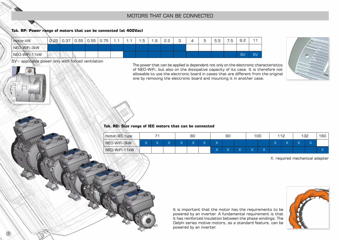
9,2 11
nEO-WiFi-3kW
nEO-WiFi-11kW SV SV
nEO-WiFi-3kW
nEO-WiFi-11kW
MOTORs ThAT CAn BE COnnECTED
motor-kW 0.25 0.37 0.55 0.55 0.75 1.1 1.1 1.5 1.9 2.2 3 4 5 5.5 7.5
Tab. RP: Power range of motors that can be connected (at 400Vac)
Tab. Rd: Size range of ieC motors that can be connected
X. required mechanical adapter
it is important that the motor has the requirements to be powered by an inverter. A fundamental requirement is that it has reinforced insulation between the phase windings. The Delphi series motive motors, as a standard feature, can be powered by an inverter.
The power that can be applied is dependent not only on the electronic characteristics of nEO-WiFi, but also on the dissipative capacity of its case. it is therefore not allowable to use the electronic board in cases that are different from the original one by removing the electronic board and mounting it in another case.
motor-iEC type 71 80 90 100 112 132 160
X X X X X X X X X X X
X X X X X X
SV=applicablepoweronlywithforcedventilation
8

187
223 126140
3911
0
110
motor-iEC type 71 80 90 100 112 132 160
X X X X X X X X X X X
X X X X X X
MEChAniCAL AssEMBLY
dimensions of neO-WiFi-3kW and keypad
9
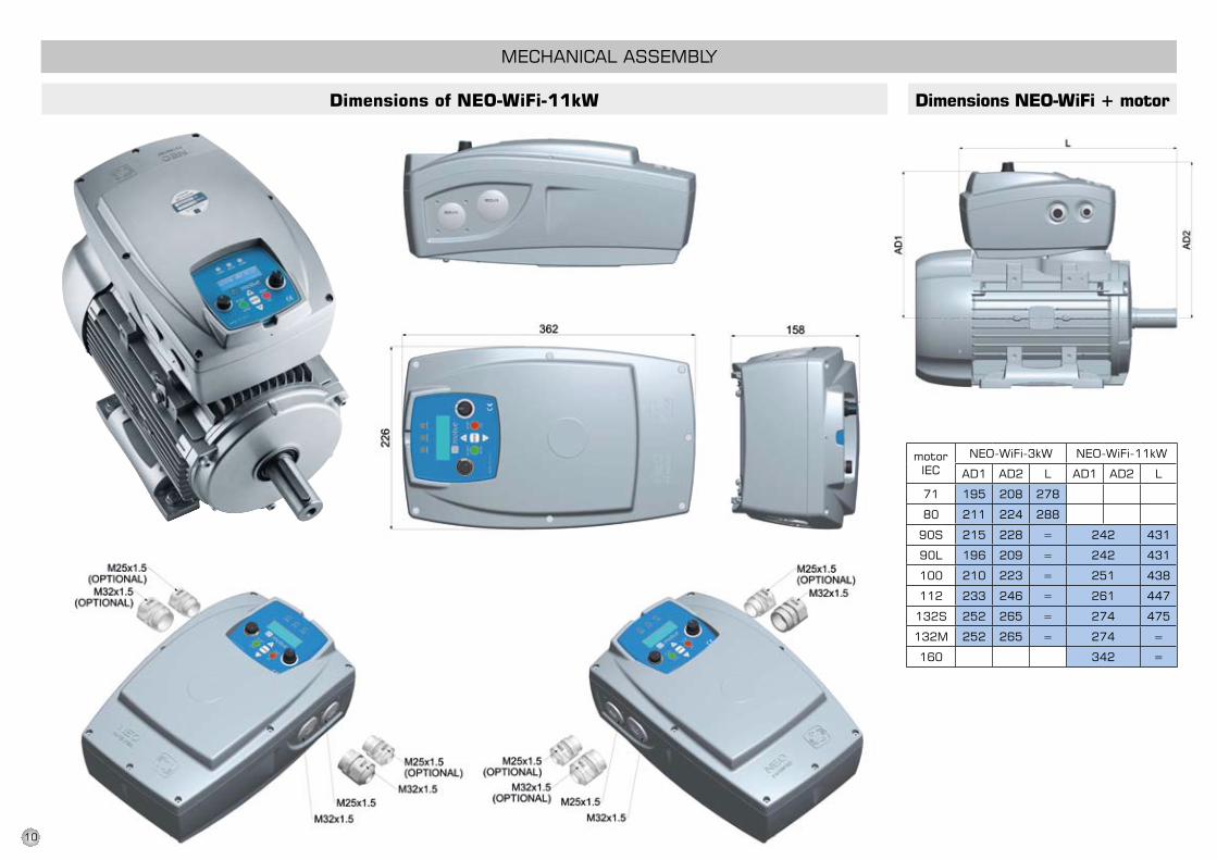
nEO-WiFi-3kW nEO-WiFi-11kW
AD1 AD2 L AD1 AD2 L
71 195 208 278
80 211 224 288
90s 215 228 = 242 431
90L 196 209 = 242 431
100 210 223 = 251 438
112 233 246 = 261 447
132s 252 265 = 274 475
132M 252 265 = 274 =
160 342 =
MEChAniCAL AssEMBLY
dimensions of neO-WiFi-11kW dimensions neO-WiFi + motor
motor iEC
10

112-132
160M 100L 90S / 90L
neO WiFi-3
neO WiFi-11
71-80-90S
MEChAniCAL AssEMBLY
Motor assembly
if the inverter is used at frequencies lower than 50hz, it becomes necessary to use motors with forced ven-tilation:
The mechanical fastening with slots (ill. 5) allows the nEO-WiFi case to be fixed onto a wide range of Delphi series motive motors from size 71 to size 160 (Table. RD)
ill. 5
For the connection between nEO-WiFi and the motors marked with X in the “Tab. RD”, specific mechanical adap-ters are needed. see the following images.
11
MEChAniCAL AssEMBLY
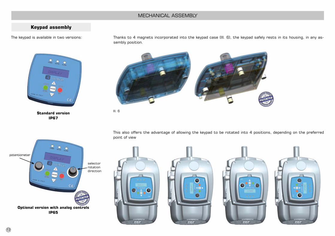
Keypad assembly
The keypad is available in two versions:
Standard versioniP67
Optional version with analog controlsiP65
Thanks to 4 magnets incorporated into the keypad case (ill. 6), the keypad safely rests in its housing, in any as-sembly position.
This also offers the advantage of allowing the keypad to be rotated into 4 positions, depending on the preferred point of view
ill. 6
potentiometer
selector rotation direction
12

MEChAniCAL AssEMBLY
if the keypad is removed from the nEO-WiFi case, it can be fixed to the wall in 2 ways.
Each keypad comes equipped with two rechargeable batteries.The rechargeable batteries, if they are regularly charged, can last for several years.
• Alternatively, it can be fixed onto 2inserts by using the designated slots on the back of the case (ill. 8)
ill. 7 ill. 8
•Ifthewallismadeofmetal,byusingthemagnetism of 4 magnets in the keypad (ill. 7).
BLOCK – keypad external induction recharger
The keypad is attracted and hold in BLOCK seat by magnets
The keypad can be positioned in any position.
The keypad is powered by induction.
BLOCKisIP65,200-260Vac1PH50/60hz
if the wall is made of metal, BLOCK is fixed by the magnetism of its 4 magnets.Alternatively, it can be fixed onto 2 inserts by using the designated slots on the back of BLOCK
13

1
J1523415V
J3
EnD1D2E1E2sETVELA
J2B
+15
J8An1An20V
J6L1L2L3U
J7VW
BR-BR+
UsB
sW1
sW2
15Vac
neO-WiFi-3
ELECTRiCAL AssEMBLY
Connection of the external devices
illustration 13 - Diagram nEO-WiFi-3kW power board
terminal function
normally open contact that closes when the motor starts
normally open contact that closes when the iGBT bridge tempera-ture exceeds 55°C
15Vdcoutput(max100mA)enables/disables the inverter operationdirection 1 (rotation sense 1 of motor)direction 2 (rotation sense 2 of motor)encoder or proximity sensor input (Channel A)encoder or proximity sensor input (Channel B)communicationchannelselection(closingthiscontactwith15V)analogueoutput1(-10V…+10V)
Rs485 (for Master-slave connection)
15Vdcoutput(max100mA)analogue input 1analogue input 20Vdc
groundinggroundingphase 1 for inverter power supply from netphase 2 for inverter power supply from netphase 3 for inverter power supply from netU phase motor connectionVphasemotorconnectionW phase motor connection
internal braking resistances connection (opt. External), or motor dc brake connection
pC connection
in On position there's a 4-20mA configuration, in OFF position there'sa0-10Vconfiguration
15Vacoutputforinductionrecharger
14
AO2J15
0VAO1
J140V15V
J165VA+
J11
A-B+B-Z+Z-0V0VA
J10BA
J9B15V
J8
An1An2D2D1sETEn0V
UsB
0VIND J4AC inD0VDCFAN J112VDCFAN
Ext FAnJ3Ext FAn
ALARM
J2ALARMMOT OnMOT On
BR+ J10BR-GnD
J9UVWL3
J5L2L1
GnD
neO-WiFi-3
ELECTRiCAL AssEMBLY
terminal function
normally open contact that closes when the motor starts
normally open contact that closes when the iGBT bridge tempera-ture exceeds 55°C
15Vdcoutput(max100mA)enables/disables the inverter operationdirection 1 (rotation sense 1 of motor)direction 2 (rotation sense 2 of motor)encoder or proximity sensor input (Channel A)encoder or proximity sensor input (Channel B)communicationchannelselection(closingthiscontactwith15V)analogueoutput1(-10V…+10V)
Rs485 (for Master-slave connection)
15Vdcoutput(max100mA)analogue input 1analogue input 20Vdc
groundinggroundingphase 1 for inverter power supply from netphase 2 for inverter power supply from netphase 3 for inverter power supply from netU phase motor connectionVphasemotorconnectionW phase motor connection
internal braking resistances connection (opt. External), or motor dc brake connection
pC connection
in On position there's a 4-20mA configuration, in OFF position there'sa0-10Vconfiguration
15Vacoutputforinductionrecharger
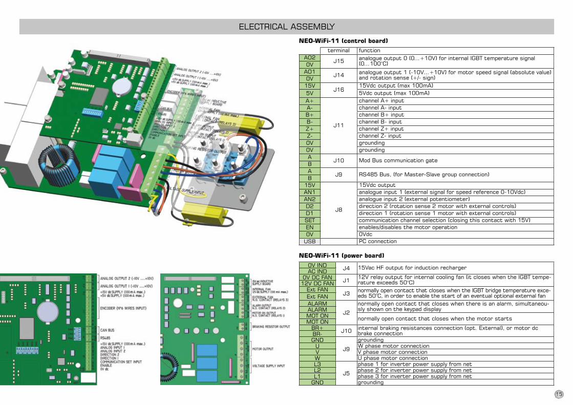
neO-WiFi-11 (control board)
neO-WiFi-11 (power board)
terminal functionanalogueoutput0(0…+10V)forinternalIGBTtemperaturesignal(0…100°C)
analogueoutput1(-10V…+10V)formotorspeedsignal(absolutevalue)and rotation sense (+/- sign)15Vdcoutput(max100mA)5Vdcoutput(max100mA)channel A+ inputchannel A- inputchannel B+ inputchannel B- inputchannel Z+ inputchannel Z- inputgroundinggrounding
Mod Bus communication gate
Rs485 Bus, (for Master-slave group connection)
15Vdcoutputanalogueinput1(externalsignalforspeedreference0-10Vdc)analogue input 2 (external potentiometer)direction 2 (rotation sense 2 motor with external controls)direction 1 (rotation sense 1 motor with external controls)communicationchannelselection(closingthiscontactwith15V)enables/disables the motor operation0VdcpC connection
15VacHFoutputforinductionrecharger
12Vrelayoutputforinternalcoolingfan(itcloseswhentheIGBTtempe-rature exceeds 50°C)normally open contact that closes when the iGBT bridge temperature exce-eds 50°C, in order to enable the start of an eventual optional external fannormally open contact that closes when there is an alarm, simultaneou-sly shown on the keypad display
normally open contact that closes when the motor starts
internal braking resistances connection (opt. External), or motor dc brake connectiongroundingW phase motor connectionVphasemotorconnectionU phase motor connectionphase 1 for inverter power supply from netphase 2 for inverter power supply from netphase 3 for inverter power supply from netgrounding
15
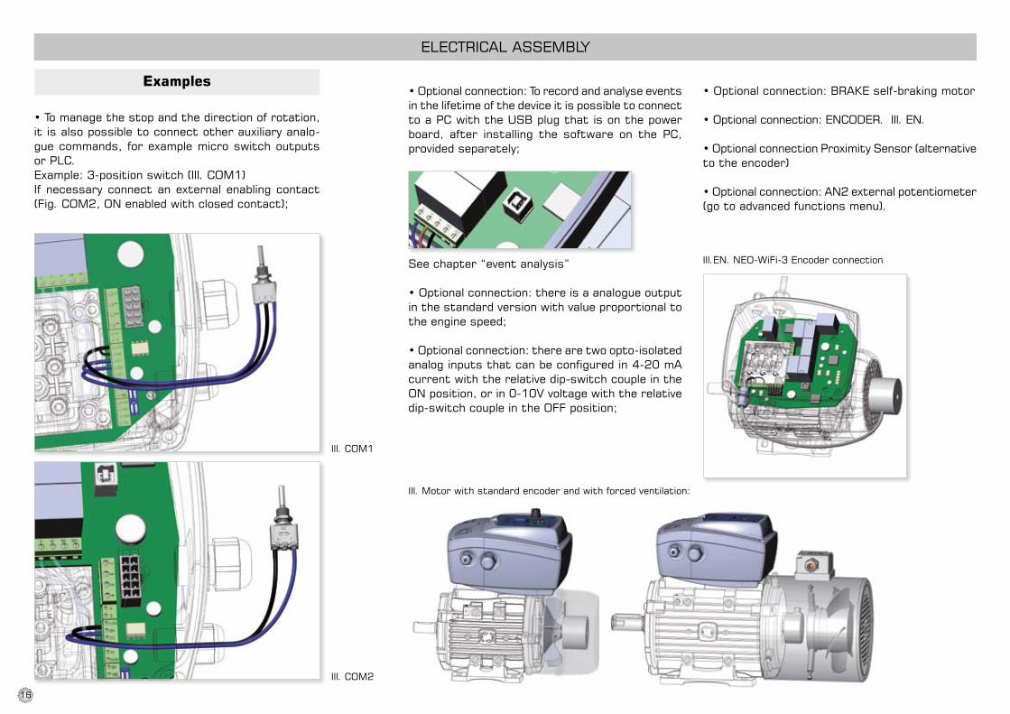
ELECTRiCAL AssEMBLY
ill. COM2
ill. COM1
•Tomanagethestopandthedirectionofrotation,it is also possible to connect other auxiliary analo-gue commands, for example micro switch outputs or pLC.Example: 3-position switch (ill. COM1)if necessary connect an external enabling contact (Fig. COM2, On enabled with closed contact);
ill.En. nEO-WiFi-3 Encoder connection
ill. Motor with standard encoder and with forced ventilation:
•Optionalconnection:Torecordandanalyseeventsin the lifetime of the device it is possible to connect to a pC with the UsB plug that is on the power board, after installing the software on the pC, provided separately;
see chapter “event analysis”
•Optionalconnection:thereisaanalogueoutputin the standard version with value proportional to the engine speed;
•Optionalconnection:therearetwoopto-isolatedanalog inputs that can be configured in 4-20 mA current with the relative dip-switch couple in the ONposition,orin0-10Vvoltagewiththerelativedip-switch couple in the OFF position;
•Optionalconnection:BRAKEself-brakingmotor
•Optionalconnection:ENCODER.Ill.EN.
•OptionalconnectionProximitySensor(alternativeto the encoder)
•Optionalconnection:AN2externalpotentiometer(go to advanced functions menu).
examples
16

pROGRAMMinG
Keypad-inverter communication
separate control of multiple motors with multiple keypads with separate channels from 1 to 127
it is instead possible to obtain a synchronous behaviour of 2-8 nEO-WiFi with one keypad, connected them in master-slave mode. slaves can function also without keypad, once they have been configured in the Rs485 connection
The keypad during the functioning of the motor shows, alternating them, the following two sets of data
power factor Motor [cos.Fi]
hertz motor power
inverter temperature
Voltmotorpower
Rev/min of the motor
Keypad-inverter communica-tion channel
Watts absorbed by the motor
Amps drawn by the motor
SincekeypadversionV1.12(youcanseeitfor2secondswhen you switch the keypad on) it is possible to see the battery charge.
For that, keep MODE pressed for a while (16 squares =fullycharged).
17
sTART
EnTER
sTOp
EsC
power On
Motor On
Alarm
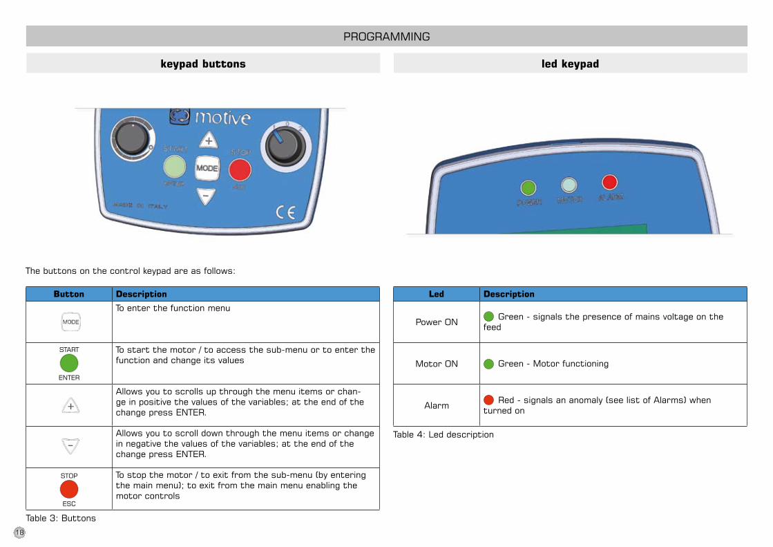
pROGRAMMinG
keypad buttons led keypad
The buttons on the control keypad are as follows:
Button description
To enter the function menu
To start the motor / to access the sub-menu or to enter the function and change its values
Allows you to scrolls up through the menu items or chan-ge in positive the values of the variables; at the end of the change press EnTER.
Allows you to scroll down through the menu items or change in negative the values of the variables; at the end of the change press EnTER.
To stop the motor / to exit from the sub-menu (by entering the main menu); to exit from the main menu enabling the motor controls
Led description
Green - signals the presence of mains voltage on the feed
Green - Motor functioning
Red - signals an anomaly (see list of Alarms) when turned on
Table 3: Buttons
Table 4: Led description
18
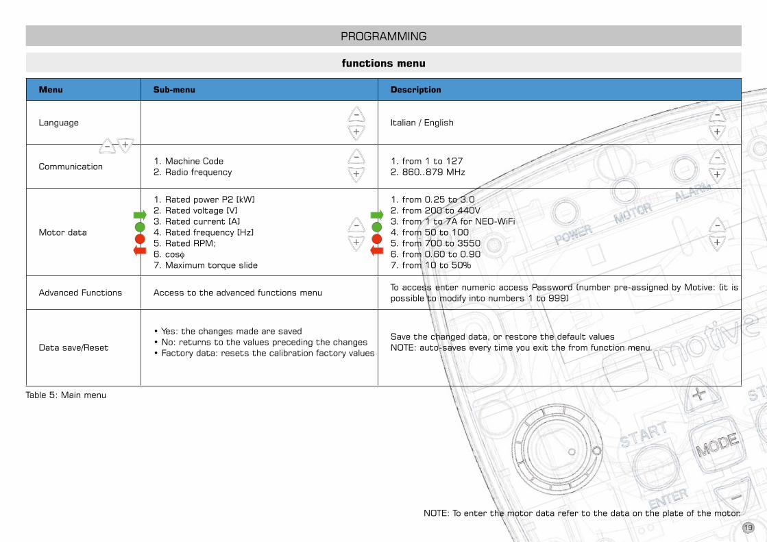
Menu Sub-menu description
Language italian / English
Communication1. Machine Code2. Radio frequency
1. from 1 to 1272. 860..879 Mhz
Motor data
1. Rated power p2 [kW]2.Ratedvoltage[V]3. Rated current [A]4. Rated frequency [hz]5. Rated RpM;6. cosφ7. Maximum torque slide
1. from 0.25 to 3.02.from200to440V3. from 1 to 7A for nEO-WiFi4. from 50 to 1005. from 700 to 35506. from 0.60 to 0.907. from 10 to 50%
Advanced Functions Access to the advanced functions menuTo access enter numeric access password (number pre-assigned by Motive: (it is possible to modify into numbers 1 to 999)
Data save/Reset
•Yes:thechangesmadearesaved•No:returnstothevaluesprecedingthechanges•Factorydata:resetsthecalibrationfactoryvalues
save the changed data, or restore the default values nOTE: auto-saves every time you exit the from function menu.
nOTE: To enter the motor data refer to the data on the plate of the motor.
pROGRAMMinG
functions menu
Table 5: Main menu
19
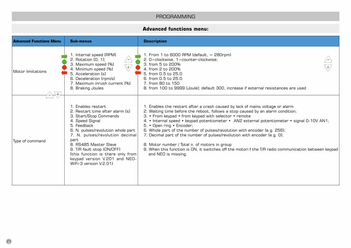
pROGRAMMinG
Advanced functions menu:
Advanced Functions Menu Sub-menus description
Motor limitations
1. internal speed [RpM]2. Rotation [0, 1];3. Maximum speed [%]4. Minimum speed [%]5. Acceleration [s]6. Deceleration [rpm/s]7. Maximum inrush current [%]8. Braking Joules
1.From1to6000RPM(default,≈280rpm)2.0=clockwise,1=counter-clockwise;3. from 5 to 200%4. from 2 to 200%5. from 0.5 to 25.06. from 0.5 to 25.07. from 80 to 1508. from 100 to 9999 [Joule]; default 300, increase if external resistances are used
Type of command
1. Enables restart2. Restart time after alarm [s] 3. start/stop Commands4. speed signal5. Feedback6. n. pulses/revolution whole part7. n. pulses/revolution decimal part8. Rs485 Master slave 9. T/R fault stop (On/OFF)(this function is there only from keypad version V.201 and NEO-WiFi-3versionV.2.01)
1. Enables the restart after a crash caused by lack of mains voltage or alarm 2. Waiting time before the reboot, follows a stop caused by an alarm condition; 3.•Fromkeypad•fromkeypadwithselector•remote4.•Internalspeed•keypadpotentiometer•AN2externalpotentiometer•signal0-10VAN1;5.•Openring•Encoder;6. Whole part of the number of pulses/revolution with encoder (e.g. 256);7. Decimal part of the number of pulses/revolution with encoder (e.g. 0);
8. Motor number / Total n. of motors in group 9. When this function is On, it switches off the motori f the T/R radio communication between keypad
and nEO is missing.
20
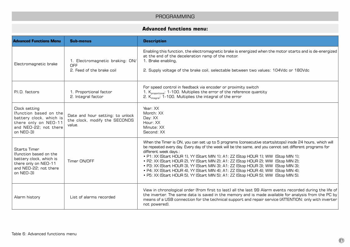
pROGRAMMinG
Advanced functions menu:
Table 6: Advanced functions menu
Advanced Functions Menu Sub-menus description
Electromagnetic brake1. Electromagnetic braking: On/OFF2. Feed of the brake coil
Enabling this function, the electromagnetic brake is energized when the motor starts and is de-energized at the end of the deceleration ramp of the motor.1. Brake enabling,
2.Supplyvoltageofthebrakecoil,selectablebetweentwovalues:104Vdcor180Vdc
p.i.D. factors 1. proportional factor2. integral factor
For speed control in feedback via encoder or proximity switch1. Kproportional: 1-100. Multiplies the error of the reference quantity2. Kintegral: 1-100. Multiplies the integral of the error
Clock setting(function based on the battery clock, which is there only on nEO-11 and nEO-22; not there on nEO-3)
Date and hour setting: to unlock the clock, modify the sECOnDs value.
Year: XXMonth: XXDay: XXhour: XXMinute: XXsecond: XX
starts Timer(function based on the battery clock, which is there only on nEO-11 and nEO-22; not there on nEO-3)
Timer On/OFF
When the Timer is On, you can set up to 5 programs (consecutive starts/stops) insde 24 hours, which will be repeated every day. Every day of the week will be the same, and you cannot set different programs for different week days.:•P1:XX(StartHOUR1),YY(StartMIN1);A1:ZZ(StopHOUR1);WW(StopMIN1);•P2:XX(StartHOUR2),YY(StartMIN2);A1:ZZ(StopHOUR2);WW(StopMIN2);•P3:XX(StartHOUR3),YY(StartMIN3);A1:ZZ(StopHOUR3);WW(StopMIN3);•P4:XX(StartHOUR4),YY(StartMIN4);A1:ZZ(StopHOUR4);WW(StopMIN4);•P5:XX(StartHOUR5),YY(StartMIN5);A1:ZZ(StopHOUR5);WW(StopMIN5).
Alarm history List of alarms recorded
Viewinchronologicalorder(fromfirsttolast)allthelast99Alarmeventsrecordedduringthelifeofthe inverter. The same data is saved in the memory and is made available for analysis from the pC by means of a UsB connection for the technical support and repair service (ATTEnTiOn: only with inverter not powered).
21

1 Current peak immediate intervention for short circuit
2 Overvoltage Overvoltage due to the generator functioning during deceleration or undervoltage
3 inverter temperature Exceeding the temperature limit on the electronic board (86°C)
4 Motor heating Motor thermal protection (it works on the same principle of thermal magnetic circuit breakers: the current)
5 Encoder problem Alarm due to a problem with the encoder with speed control in feed-back
6 Enable Off Enable contact between En and C open
7 Overcurrent/Locked rotor Working only with speed control feedback via encoder, if locked for more than 10 seconds
8 in-OUT inversion possible inversion error of the input and output cables of motor and line
9 Undervoltage Voltagevalueinsufficienttokeeptheenginerunningatagivenloadcondition
10 Communication error Radio communication error between keypad and inverter – possible interference on the transmitted signal or incompatibility of keypad and inverter software versions.
pROGRAMMinG
alarms (from V1.10):
22
EVENTANALYSISDECLARATiOn OF COnFORMiTY
This software is a tool dedica-ted exclusively to authorized Motive service centers. it is meant for the verification of possible anomalies or failu-res. in fact: •itactsasablackboxforthediagnosis and analysis of pro-blems of specific applications with the inverter. Ability to store over 8000 events that occurred over time.
• displays all the elec-trical quantities during the alarm events that occurred while the pro-duct is functioning.
• Counts the workinghours with inverter tur-ned on and the motor running
• Shows time graphsof electrical quantities, voltages and currents
•Displaysthehistogramofeventsthatoccurred over time, being able to assess the greater or lesser recurrence of some of these events.
The screens shown above are purely indicative. For details on this sW, see the specific manual.
72/74
NEO-WiFi– manual - ENG REV04-JUN13
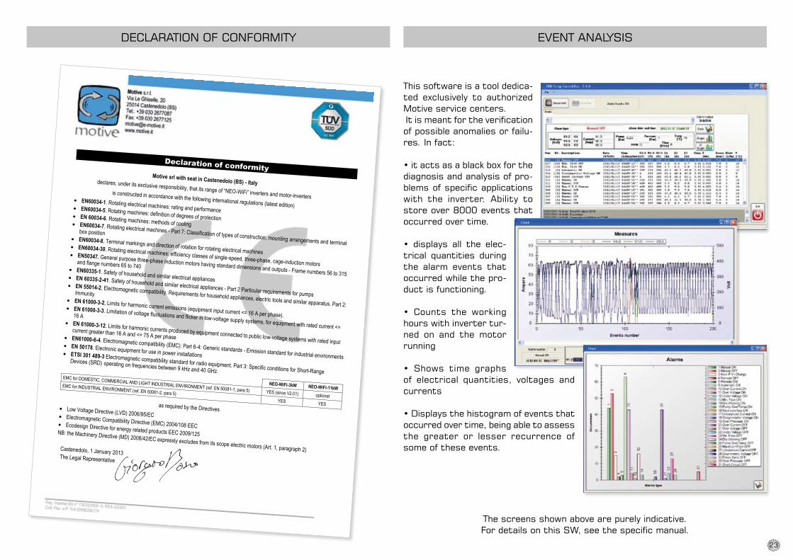
Declaration of conformity
Motive srl with seat in Castenedolo (BS) - Italy declares, under its exclusive responsibility, that its range of “NEO-WiFi” inverters and motor-inverters is constructed in accordance with the following international regulations (latest edition)
• EN60034-1. Rotating electrical machines: rating and performance • EN60034-5. Rotating machines: definition of degrees of protection • EN 60034-6. Rotating machines: methods of cooling • EN60034-7. Rotating electrical machines - Part 7: Classification of types of construction, mounting arrangements and terminal
box position • EN60034-8. Terminal markings and direction of rotation for rotating electrical machines • EN60034-30. Rotating electrical machines: efficiency classes of single-speed, three-phase, cage-induction motors
• EN50347. General purpose three-phase induction motors having standard dimensions and outputs - Frame numbers 56 to 315
and flange numbers 65 to 740 • EN60335-1. Safety of household and similar electrical appliances • EN 60335-2-41. Safety of household and similar electrical appliances - Part 2 Particular requirements for pumps
• EN 55014-2, Electromagnetic compatibility. Requirements for household appliances, electric tools and similar apparatus. Part 2:
Immunity • EN 61000-3-2, Limits for harmonic current emissions (equipment input current <= 16 A per phase). • EN 61000-3-3. Limitation of voltage fluctuations and flicker in low-voltage supply systems, for equipment with rated current <=
16 A • EN 61000-3-12. Limits for harmonic currents produced by equipment connected to public low-voltage systems with rated input
current greater than 16 A and <= 75 A per phase • EN61000-6-4. Electromagnetic compatibility (EMC): Part 6-4: Generic standards - Emission standard for industrial environments
• EN 50178. Electronic equipment for use in power installations • ETSI 301 489-3 Electromagnetic compatibility standard for radio equipment. Part 3: Specific conditions for Short-Range
Devices (SRD) operating on frequencies between 9 kHz and 40 GHz.
NEO-WiFi-3kW NEO-WiFi-11kW
EMC for DOMESTIC, COMMERCIAL AND LIGHT INDUSTRIAL ENVIRONMENT (ref. EN 50081-1, para 5) YES (since V2.01) optional
EMC for INDUSTRIAL ENVIRONMENT (ref. EN 50081-2, para 5)
YES YES
as required by the Directives • Low Voltage Directive (LVD) 2006/95/EC • Electromagnetic Compatibility Directive (EMC) 2004/108 EEC • Ecodesign Directive for energy related products EEC 2009/125 NB: the Machinery Directive (MD) 2006/42/EC expressly excludes from its scope electric motors (Art. 1, paragraph 2)
Castenedolo, 1 January 2013 The Legal Representative
23

24
dOWnLOAd The TeChniCAL MAnUAL FROM
WWW.MOTiVe.iT
ARTiCLE 1GUARAnTee
1.1 Barring written agreements, entered into between the parties hereto each time, Motive hereby guarantees compliance with spe-cific agreements.The guarantee for defects shall be restricted to product defects following design, materials or ma-nufacturing defects leading back to Motive.The guarantee shall not include: * Faults or damages ensuing from
transport. Faults or damages ensuing from installation de-fects; incompetent use of the product, or any other unsuitable use.
* Tampering or damages ensuing from use by non-authorised staff and/or use of non-original parts and/or spare parts;
* Defects and/or damages ensuing from chemical agents and/or atmospheric phenomena (e.g. burnt out material, etc.); rou-tine maintenance and required action or checks;
* products lacking a plate or ha-ving a tempered plate.
1.2 Returns to credit or replace will be accepted only in exceptional cases; however returns of goods already used to credit or replace won’t be accepted in any case.The guarantee shall be effective for all Motive products, with a term of validity of 12 months, starting from the date of shipment.The guarantee shall be subject to specific written request for Motive to take action, according to statements, as described at
TERMs OF sALE AnD GUARAnTEE
the paragraphs herein below. By virtue of aforesaid approval, and as regards the claim, Motive shall be bound at its discretion, and within a reasonable time-limit, to alternatively take the following actions:a) To supply the Buyer with products of the same type and quality as those having proven defective and not complying with agreements, free ex-works; in aforesaid case, Motive shall have the right to request, at Buyer’s charge, early return of defective goods, which shall become Moti-ve’s property;b) To repair, at its charge , the defective product or to modify the product which does not comply with agreements, by performing aforesaid action at its facilities; in aforesaid cases, all costs re-garding product transport shall be sustained by the Buyer.c) To send spare parts free of charge: all costs regarding pro-duct transport shall be sustained by the Buyer.
1.3. The guarantee herein shall assimilate and replace legal gua-rantees for defects and discre-pancies, and shall exclude any other eventual Motive liability, however caused by supplied pro-ducts; in particular, the Buyer shall have no right to submit any further claims.Motive shall not be liable for the enforcement of any further claims, as of the date the guarantee’s term of validity expires.
ALLDATAHAVEBEENWRITTENANDChECKED WiTh ThE
GREATEsT CARE.WE DO nOT TAKE AnY REspOnsi-BiLiTY FOR pOssiBLE ERRORs OR
OMissiOns.MOTIVECANCHANGETHE
ChARACTERisTiC OF ThE sOLD iTEMs On his FiRM OpiniOn AnD
INEVERYMOMENT.
ARTiCLE 2CLAiMS
2.1. Claims, regarding quantity, weight, gross weight and colour, or claims regarding faults and de-fects in quality or compliance, and which the Buyer may discover on goods delivery, shall be submitted by a max.7 days of aforesaid disco-very, under penalty of nullity.
ARTiCLE 3deLiVeRY
3.1. Any liability for damages ensuing from total or partial de-layed or failed delivery, shall be excluded.
3.2. Unless differently commu-nicated by written to the Client, the transport terms have to be intended ex-works.
ARTiCLE 4PAYMenT
4.1. Any delayed or irregular pay-ments shall entitle Motive to can-cel ongoing agreement, including agreements which do not regard the payments at issue, as well as entitling Motive to claim damages, if any. Motive shall, however, have the right, as of payment’s due date and without placing in arre-ars, to claim interest for arrears, to the extent of the discount rate in force in italy, increased by 12 points. Motive shall also have the right to withhold material under repair for replacement. in the case of failed payment, Motive shall have the right to cancel all gua-rantees of materials, as regards the insolvent Client.
4.2. The Buyer shall be bound to complete payment, including ca-ses whereby claims or disputes are underway.
24

visit and know motive thanks to the movie on www.motive.it
Motive s.r.l.
Via Le Ghiselle, 20
25014 Castenedolo (BS) - Italy
Tel.: +39.030.2677087 - Fax: +39.030.2677125
web site: www.motive.it
e-mail: [email protected]
Loo
kS
Good, perFormS BeTTe
r
neo
-wiF
i TeC
hn
ICa
L CaT
aLo
GU
e e
nG
aG
o 1
3 r
eV.
02
area dISTrIBUTor
ask our further catalogues:
Motive s.r.l.
Via Artigianale, 110/112 - 25010 MONTIRONE (BS) - Italy
Tel. +39.030.2677087 - Fax +39.030.2677125
web site: www.motive.it - e-mail: [email protected]
delphi series asynchronous
three-phase electric motors
ROBUS in-line helical geaRBOxBOX SERIES WORMGEAR UNITS
loo
ks
good, performs bette
r
g e n e r a l c a t a l o g u e


![Careless Whisper Difficulty = George Michael - Moselele · Careless Whisper Difficulty = a George Michael CHORDS USED IN THIS SONG Dm Gm7 Bb Am [Dm] [Gm7] [Bb] [Am] [Dm] [Gm7] [Bb]](https://img.pdfslide.us/doc/110x75/5adac5377f8b9ae1768d9b6d/careless-whisper-difficulty-george-michael-moselele-whisper-difficulty-a-george.jpg)