Embed Size (px)
Citation preview

Variable Speed Drive FDU 2.0
Instruction Manual - English

Variable speed drive FDU 2.0
INSTRUCTION MANUAL - ENGLISH
Software version 4.0x
Document number: 01-3694-01Edition: r1aDate of release: 25-08-2006© Copyright Emotron AB 2005 - 2006Emotron retains the right to change specifications and illustrations in the text, without prior notification. The contents of this document may not be copied without the explicit permission of Emotron AB.

Emotron AB 01-3694-01r1a 1
Safety Instructions
Instruction manualRead the instruction manual first!
Handling the variable speed driveInstallation, commissioning, demounting, taking measure-ments, etc, of or on the variable speed drive may only be car-ried out by personnel technically qualified for the task. The installation must be carried out in accordance with local standards.
Opening the variable speed drive
WARNING: Always switch off the mains voltage before opening the variable speed drive and wait at least 5 minutes to allow the buffer capacitors to discharge.
Always take adequate precautions before opening the varia-ble speed drive. Although the connections for the control signals and the switches are isolated from the main voltage, do not touch the control board when the variable speed drive is switched on.
Precautions to be taken with a connected motorIf work must be carried out on a connected motor or on the driven machine, the mains voltage must always be discon-nected from the variable speed drive first. Wait at least 5 minutes before starting work.
EarthingThe variable speed drive must always be earthed via the mains safety earth connection, indicated by “PE”.
Earth leakage currentThis VSD has an earth leakage current which does exceeding 3.5 mA a.c. or 10 mA d.c. Therefore the minimum size of the protective earth conductor must comply with the local safety regulations for high leakage current equipment.
Residual current device (RCD) compatibilityThis product cause a d.c. current in the protective conduc-tor. Where a residual current device (RCD) is used for pro-tection in case of direct or indirect contact, only a Type B RCD is allowed on the supply side of this product. Use RCD of 300 mA minimum.
EMC RegulationsIn order to comply with the EMC Directive, it is absolutely necessary to follow the installation instructions. All installa-tion descriptions in this manual follow the EMC Directive.
Mains voltage selectionThe variable speed drive is suitable for use with the mains voltage listed below. Adjustment of the mains voltage is not necessary!
380-415 V380-480 V440-525 V500-690 V
Voltage tests (Megger)Do not carry out voltage tests (Megger) on the motor, before all the motor cables have been disconnected from the varia-ble speed drive.
CondensationIf the variable speed drive is moved from a cold (storage) room to a room where it will be installed, condensation can occur. This can result in sensitive components becoming damp. Do not connect the mains voltage until all visible dampness has evaporated.
Incorrect connectionThe variable speed drive is not protected against incorrect connection of the mains voltage, and in particular against connection of the mains voltage to the motor outlets U, V and W. The variable speed drive can be damaged in this way.
Power factor capacitors for improving cosϕRemove all capacitors from the motor and the motor outlet.
Precautions during AutoresetWhen the automatic reset is active, the motor will restart automatically provided that the cause of the trip has been removed. If necessary take the appropriate precautions.
TransportTo avoid damage, keep the variable speed drive in its original packaging during transport. This packaging is specially designed to absorb shocks during transport.

2 Emotron AB 01-3694-01r1a
IT Mains supplyThe variable speed drives can easily be connected to a IT mains supply, (non-earthed neutral), please contact your supplier for details.

Emotron AB 01-3694-01r1a 3
Contents
1. Introduction..................................................... 5
1.1 Delivery and unpacking ............................................ 51.2 Using of the instruction manual ............................... 51.3 Type number.............................................................. 51.4 Standards .................................................................. 61.4.1 Product standard for EMC ........................................ 61.5 Dismantling and scrapping....................................... 71.5.1 Disposal of old electrical and electronic equipment ..
71.6 Glossary ..................................................................... 71.6.1 Abbreviations............................................................. 71.6.2 Definitions.................................................................. 7
2. Mounting ......................................................... 9
2.1 Lifting instructions..................................................... 92.2 Stand-alone units ...................................................... 92.2.1 Cooling ..................................................................... 102.2.2 Mounting schemes.................................................. 102.3 Cabinet mounting.................................................... 122.3.1 Cooling ..................................................................... 122.4 Mounting the control panel in a cabinet ............... 12
3. Installation ................................................... 13
3.1 Before installation................................................... 133.2 Cable connections................................................... 133.2.1 Motor cables............................................................ 133.2.2 Mains cables ........................................................... 153.3 Cable specifications................................................ 153.4 Stripping lengths ..................................................... 153.4.1 Dimension of cables and fuses.............................. 163.4.2 Tightening torque for mains and motor cables..... 163.5 Connect motor and mains cables .......................... 163.6 Thermal protection on the motor ........................... 173.7 Motors in parallel .................................................... 17
4. Control Connections.................................... 19
4.1 Control board........................................................... 194.2 Terminal connections ............................................. 204.3 Connection example ............................................... 214.4 Inputs configuration
with the switches..................................................... 224.5 Connecting the Control Signals.............................. 224.5.1 Cables ...................................................................... 224.5.2 Types of control signals .......................................... 234.5.3 Screening................................................................. 234.5.4 Single-ended or double-ended connection? ......... 234.5.5 Current signals ((0)4-20 mA).................................. 234.5.6 Twisted cables......................................................... 244.6 Connecting options ................................................. 24
5. Getting Started............................................. 25
5.1 Connect the mains and motor cables ................... 255.1.1 Mains cables ........................................................... 255.1.2 Motor cables............................................................ 255.2 Connect control cables ........................................... 255.3 Using the function keys .......................................... 265.4 Remote control........................................................ 265.4.1 Switch on the mains ............................................... 265.4.2 Set the Motor Data.................................................. 265.4.3 Run the VSD ............................................................ 265.5 Local control ............................................................ 275.5.1 Switch on the mains ............................................... 275.5.2 Select manual control............................................. 275.5.3 Set the Motor Data.................................................. 275.5.4 Enter a Reference Value......................................... 275.5.5 Run the VSD ............................................................ 27
6. Applications.................................................. 29
6.1 Application overview ............................................... 296.1.1 Pumps...................................................................... 296.1.2 Fans ......................................................................... 296.1.3 Compressors ........................................................... 306.1.4 Blowers .................................................................... 30
7. Main Features .............................................. 31
7.1 Parameter sets........................................................ 317.1.1 One motor and one parameter set ........................ 327.1.2 One motor and two parameter sets....................... 327.1.3 Two motors and two parameter sets ..................... 327.1.4 Autoreset at trip ...................................................... 327.1.5 Reference priority.................................................... 327.1.6 Preset references.................................................... 337.2 Remote control functions ....................................... 337.3 Performing an Identification Run........................... 357.4 Using the Control Panel Memory............................ 367.5 Load Monitor and Process Protection [400] ......... 367.5.1 Load Monitor [410]................................................. 367.6 Pump function ......................................................... 387.6.1 Introduction ............................................................. 387.6.2 Fixed MASTER ......................................................... 397.6.3 Alternating MASTER ................................................ 397.6.4 Feedback 'Status' input .......................................... 397.6.5 Fail safe operation .................................................. 407.6.6 PID control ............................................................... 417.6.7 Wiring Alternating Master ....................................... 427.6.8 Checklist And Tips................................................... 437.6.9 Functional Examples of Start/Stop Transitions .... 44
8. EMC and Machine Directive........................ 47
8.1 EMC standards........................................................ 478.2 Stop categories and emergency stop .................... 47

4 Emotron AB 01-3694-01r1a
9. Operation via the Control Panel ................. 49
9.1 General .................................................................... 499.2 The control panel .................................................... 499.2.1 The display............................................................... 499.2.2 Indications on the display....................................... 509.2.3 LED indicators ......................................................... 509.2.4 Control keys............................................................. 509.2.5 The Toggle and Loc/Rem Key ................................ 509.2.6 Function keys .......................................................... 519.3 The menu structure................................................. 529.3.1 The main menu ....................................................... 529.4 Programming during operation .............................. 529.5 Editing values in a menu ........................................ 529.6 Programming example............................................ 53
10. Serial communication ................................. 55
10.1 Description of the EInt formats .............................. 55
11. Functional Description................................ 59
11.1 Resolution of settings ............................................. 5911.2 Preferred View [100]............................................... 5911.2.1 1st Line [110].......................................................... 5911.2.2 2nd Line [120] ........................................................ 5911.3 Main Setup [200] .................................................... 6011.3.1 Operation [210]....................................................... 6011.3.2 Start Signal Level/Edge [21A]................................ 6311.3.3 Motor Data [220] .................................................... 6311.3.4 Motor Protection [230] ........................................... 6711.3.5 Parameter Set Handling [240] ............................... 6911.3.6 Trip Autoreset/Trip Conditions [250]..................... 7111.3.7 Serial Communication [260] .................................. 7711.4 Process & Application Parameters [300] .............. 7911.4.1 Set/View Reference Value [310] ........................... 7911.4.2 Process Settings [320] ........................................... 7911.4.3 Start/Stop settings [330] ....................................... 8311.4.4 Speeds [340]........................................................... 8811.4.5 Torques [350].......................................................... 9011.4.6 Preset References [360] ........................................ 9211.4.7 PID Process Control [380] ...................................... 9311.4.8 Pump/Fan Control [390] ........................................ 9411.5 Load Monitor and Process Protection [400] ....... 10111.5.1 Load Monitor [410] ............................................... 10111.5.2 Process Protection [420]...................................... 10511.6 I/Os and Virtual Connections [500]..................... 10611.6.1 Analogue Inputs [510] .......................................... 10611.6.2 Digital Inputs [520] ............................................... 11211.6.3 Analogue Outputs [530] ....................................... 11411.6.4 Digital Outputs [540] ............................................ 11711.6.5 Relays [550] .......................................................... 11911.6.6 Virtual Connections [560]..................................... 12011.7 Logical Functions and Timers [600] .................... 12111.7.1 Comparators [610] ............................................... 12111.7.2 Logic Output Y [620] ............................................. 12511.7.3 Logic Output Z [630] ............................................. 12711.7.4 Timer1 [640] ......................................................... 12811.7.5 Timer2 [650] ......................................................... 129
11.8 View Operation/Status [700] ............................... 13011.8.1 Operation [710]..................................................... 13011.8.2 Status [720] .......................................................... 13211.8.3 Stored values [730] .............................................. 13511.9 View Trip Log [800] ............................................... 13611.9.1 Trip Message log [810]......................................... 13611.9.2 Trip Messages [820] - [890] ................................ 13711.9.3 Reset Trip Log [8A0] ............................................. 13811.10 System Data [900]................................................ 13811.10.1 VSD Data [920] ..................................................... 138
12. Troubleshooting, Diagnoses andMaintenance .............................................. 141
12.1 Trips, warnings and limits..................................... 14112.2 Trip conditions, causes and remedial action ...... 14212.2.1 Technically qualified personnel............................ 14212.2.2 Opening the variable speed drive ........................ 14212.2.3 Precautions to take with a connected motor ...... 14212.2.4 Autoreset Trip ........................................................ 14212.3 Maintenance ......................................................... 145
13. Options........................................................ 147
13.1 Protection class IP54............................................ 14713.2 Options for the control panel................................ 14713.3 EmoSoftCom.......................................................... 14813.4 Brake chopper....................................................... 14813.5 I/O Board ............................................................... 14913.6 Output coils ........................................................... 14913.7 Serial communication and fieldbus ..................... 14913.8 Standby supply option .......................................... 14913.9 Safe Stop option.................................................... 14913.10 Crane option board ............................................... 15113.11 PTC, PT100, Encoder ............................................ 151
14. Technical Data ........................................... 153
14.1 Electrical specifications related to model ........... 15314.2 General electrical specifications.......................... 15514.3 Operation at higher temperatures ....................... 15614.4 Operation at higher switching frequency............. 15614.5 Dimensions and Weights...................................... 15714.6 Environmental conditions..................................... 15714.7 Fuses, cable cross-sections and glands.............. 15814.8 Control signals....................................................... 159
15. Menu List .................................................... 161
Index 167
Emotron AB 01-3694-01r1a Introduction 5
1. Introduction
Emotron FDU is especially designed for applications with quadratic load characteristics. FDU is used most commonly to control and protect pump and fan applications that put high demands on flow control, process uptime and low maintenance costs. It can also be used for e.g. compressors and blowers. Several options are available, listed in chapter 13. page 147, that enable you to customize the variable speed drive for your specific needs.
The following symbols can appear in this manual. Always read these first before continuing:
UsersThis instruction manual is intended for:
• installation engineers
• maintenance engineers
• operators
• service engineers
MotorsThe variable speed drive is suitable for use with standard 3-phase asynchronous motors. Under certain conditions it is possible to use other types of motors. Contact your supplier for details.
1.1 Delivery and unpackingCheck for any visible signs of damage. Inform your supplier immediately of any damage found. Do not install the varia-ble speed drive if damage is found.
The variable speed drives are delivered with a template for positioning the fixing holes on a flat surface. Check that all items are present and that the type number is correct.
1.2 Using of the instruction manual
Within this instruction manual the abbreviation “VSD” is used to indicate the complete variable speed drive as a single unit.
Check that the software version number on the first page of this manual matches the software version in the variable speed drive.
With help of the index and the contents it is easy to track individual functions and to find out how to use and set them.
The Quick Setup Card can be put in a cabinet door, so that it is always easy to access in case of an emergency.
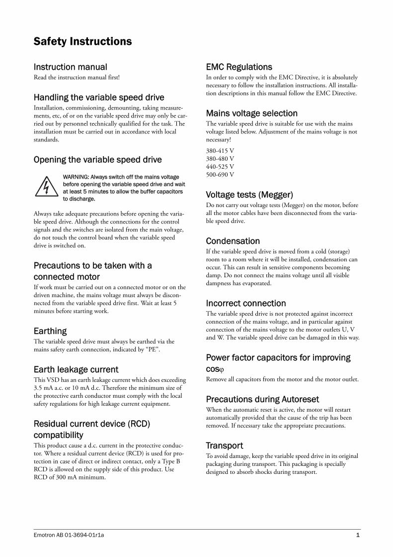
1.3 Type numberFig. 1 gives an example of the type code numbering used on all variable speed drives. With this code number the exact type of the drive can be determined. This identification will be required for type specific information when mounting and installing. The code number is located on the product label, on the front of the unit.
Fig. 1 Type number
NOTE: Read this instruction manual carefully before starting installation, connection or working with the variable speed drive.
NOTE: Additional information as an aid to avoid problems.
CAUTION: Failure to follow these instructionscan result in malfunction or damage to thevariable speed drive.
WARNING: Failure to follow these instructionscan result in serious injury to the user in addition to serious damage to the variable speed drive.
!
“20”=IP20Ingress protection
“50” = 440-525V
“40” = 380-415VSupply voltage
EMC kit“E”= EMC kit fitted
Brake chopper“B”= Brake chopper fitted
“C”= Control Panel FittedControl Panel
Rated current (A) continuous
FDU 40 146- 20 C E B
(06-F91)
Example:
VSD FDU“69” = 500-690V
“54”=IP54
“48” = 380-480 V

6 Introduction Emotron AB 01-3694-01r1a
1.4 StandardsThe variable speed drives described in this instruction man-ual comply with the standards listed in Table 1. For the dec-larations of conformity and manufacturer’s certificate, contact your supplier for more information or visit www.emotron.com.
1.4.1Product standard for EMCThe product standard EN 61800-3 defines the
First Environment as environment that includes domestic premises. It also includes establishments directly connected without intermediate transformers to a low voltage power supply network that supplies buildings used for domestic purposes.
Second Environment includes all other establishments. The variable speed drive complies with the product standard EN 61800-3, including amendment A11 (Any kind of metal screened cable may be used). The standard variable speed drive is designed to meet the requirements for the Sec-ond Environment.
WARNING: This is a product belongint to the restricted sales distribution class according to EN 61800-3. In a domestic environment this product may cause radio interference, in which case the user may be required to take adequate measures.
CAUTION: In order to comply fully with the standards stated in the Manufacturer’s Declaration ANNEX IIB, the installation instructions detailed in this instruction manual must be followed to the letter.
!
Table 1 Standards
Market Standard Description
European
Machine Directive 98/37/EEC
EMC Directive 89/336/EEC (Amendments 91/263/EEC, 92/31/EEC, 93/68/EEC)
Low Voltage Directive 73/23/EEC (Amendment 93/68/EEC)
WEEE Directive 2002/96/EC
All
EN 60204-1
Safety of machinery - Electrical equipment of machinesPart 1: General requirements.Machine Directive: Manufacturer’s certificate
acc. to Appendix IIB
EN 61800-3A11 2nd Environment
Adjustable speed electrical power drive systemsPart 3: EMC product standard including specific test methods.EMC Directive: Declaration of Conformity and
CE marking
EN50178(<90 A)
Electronic equipment for use in power installations.Low Voltage Directive: Declaration of Conformity and
CE marking
EN 61800-5-1(≥90 A)
Adjustable speed electrical power drive systems Part 5-1. Safety requirements - Electrical, thermal and energy.
Low Voltage Directive: Declaration of Conformity andCE marking
IEC 60721-3-3
Classification of environmental conditions. Air quality chemical vapours, unit in operation. Chemical gases 3C1, Solid particles 3S2.Optional with coated boardsUnit in operation. Chemical gases Class 3C2, Solid particles 3S2.

Emotron AB 01-3694-01r1a Introduction 7
1.5 Dismantling and scrappingThe enclosures of the drives are made from recyclable mate-rial as aluminium, iron and plastic. Each drive contains a number of components demanding special treatment, for example electrolytic capacitors. The circuit boards contain small amounts of tin and lead. Any local or national regula-tions in force for the disposal and recycling of these materials must be complied with.
1.5.1Disposal of old electrical and electronic equipment
This information is applicable in the European Union and other European countries with separate collection systems.
This symbol on the product or on its packaging indicates that this product shall be treated according to the WEEE Directive. It must be taken to the applicable collection point for the recycling of electrical and electronic equipment. By ensuring this product is disposed of correctly, you will help prevent potentially negative consequences for the environ-ment and human health, which could otherwise be caused by inappropriate waste handling of this product. The recy-cling of materials will help to conserve natural resources. For more detailed information about recycling this product, please contact the local distributor of the product or visit our home page www.emotron.com.
1.6 Glossary
1.6.1AbbreviationsIn this manual the following abbreviations are used:
1.6.2 DefinitionsIn this manual the following definitions for current, torque and frequency are used:
Table 2 Abbreviations
Abbreviation Description
DSP Digital signals processor
VSD Variable speed drive
CPControl panel, the programming and pres-entation unit on the VSD
EInt Communication format
UInt Communication format
Int Communication format
Long Communication format
Table 3 Definitions
Name Description Quantity
IIN Nominal input current of VSD A, RMS
INOM Nominal output current of VSD A, RMS
IMOT Nominal motor current A, RMS
PNOM Nominal power of VSD kW
PMOT Motor power kW
TNOM Nominal torque of motor Nm
TMOT Motor torque Nm
fOUT Output frequency of VSD Hz
fMOT Nominal frequency of motor Hz
nMOT Nominal speed of motor rpm
ICL Maximum output current for 60s A, RMS
Speed Actual motor speed rpm
Torque Actual motor torque Nm
Sync speed
Synchronous speed of the motor rpm

8 Introduction Emotron AB 01-3694-01r1a

Emotron AB 01-3694-01r1a Mounting 9
2. Mounting
This chapter describes how to mount the VSD.
Before mounting it is recommended that the installation is planned out first.
• Be sure that the VSD suits the mounting location.
• The mounting site must support the weight of the VSD.
• Will the VSD continuously withstand vibrations and/orshocks?
• Consider using a vibration damper.
• Check ambient conditions, ratings, required cooling airflow, compatibility of the motor, etc.
• Know how the VSD will be lifted and transported.
2.1 Lifting instructions
Recommended
Fig. 2 Recommended
Allowed
Fig. 3 Allowed
2.2 Stand-alone unitsThe VSD must be mounted in a vertical position against a flat surface. Use the template (delivered together with the VSD) to mark out the position of the fixing holes.
Fig. 4 Variable speed drive mounting models 003 to 250
Note: To prevent personal risks and any damage to the unit during lifting, it is advised that the lifting methods described blow are used.
VSD
VSD
<100°

10 Mounting Emotron AB 01-3694-01r1a
2.2.1 CoolingFig. 4 shows the minimum free space required around the VSD for the models 003 to 250 in order to guarantee ade-quate cooling. Because the fans blow the air from the bot-tom to the top it is advisable not to position an air inlet immediately above an air outlet.
The following minimum separation between two variable speed drives, a VSD and a non-dissipating wall must be maintained:
2.2.2 Mounting schemes
Fig. 5 VSD models 003 - 013 (X1)
Fig. 6 Cable interface for mains, motor and communication, VSD models 003 - 013(X1)
Fig. 7 VSD models 018 - 037 (S2)
Table 4 Mounting and cooling
003-013
018-037
046-037
090-250
FDU-FDU(mm)
a 200 200 200 200b 200 200 200 200c 30 0 30 0d 30 0 30 0
FDU-wall(mm)
a 100 100 100 100b 100 100 100 100c 30 0 30 0d 30 0 30 0
154,5
20 180
7,538
5
400
220
Ø 7 (4x)
Ø 13 (2x)
ExternalInterface
GlandsM20
273
23,75 128,5
1051
0
176
Ø7 (4x)
530
Ø13 (2x)
Emotron AB 01-3694-01r1a Mounting 11
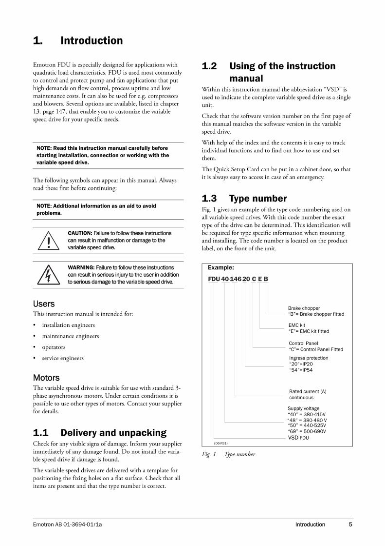
Fig. 8 Cable interface for mains, motor and communication, VSD models 018 - 037 (S2).
Fig. 9 VSD models 046 - 073 (X2)
Fig. 10 Cable interface for mains, motor and communication, VSD models 046 - 073 (X2).
Fig. 11 VSD models 090 - 175 including cable interface for mains, motor and communication (E)
ExternalInterface
GlandsM20
GlandsM25 M32M32
1057
0
220
30 160Ø
13 (2x)
Ø7 (4x)
590
ExternalInterface
GlandsM20
GlandsM40
284,50
275
3092
2,50
120240
Ø9 (6
x)
Ø16 (3
x)
1092
5
22,5095
2,50
314
GlandsM63

12 Mounting Emotron AB 01-3694-01r1a
Fig. 12 VSD models 210 - 250 including cable interface for mains, motor and communication (F)
2.3 Cabinet mounting
2.3.1 CoolingIf the variable speed drive is installed in a cabinet, the rate of airflow supplied by the cooling fans must be taken into con-sideration.
2.4 Mounting the control panel in a cabinet
In stand-alone units the control panel is mounted in the front door of the VSD. If the VSD is mounted in a cabinet, it may be appropriate tp place the control panel in the cabi-net door.
Mounting hole for the mounting frameIt is possible to retro mount a control panel in a cabinet door.
1. Mount the mounting cassette according to the drawing delivered with the mounting cassette.
2. Loosen the panel from the mounting cassette in the VSD.
3. Connect a straight RS232 cable (1-1, 2-2, .., 9-9) from the female D-Sub contact behind the control panel on the VSD.
4. Connect the other end of the cable to the male D-Sub contact on the mounting cassette in the cabinet door.
5. Snap a blank panel into the cassette on the VSD.
6. Snap the control panel into the mounting cassette in the cabinet door.
Fig. 13 A VSD with a control panel mounted in the cabinet door
Table 5 Flow rates cooling fans
FDU Model Flow rate [m3/hour]
003 – 013 40
018 – 037 150
046 – 073 165
090 – 175 510
210 – 250 800
335344,5
3092
2,50
30022.50
1092
5
952,5
0150
Ø16 (
3x)
Ø9 (6
x)
314
Cable dimensions 27-66 mm
NOTE: The RS232 cable is a standard cable.
PREV NEXT ESC
ENTER
RESET

Emotron AB 01-3694-01r1a Installation 13
3. Installation
The description of installation in this chapter complies with the EMC standards and the Machine Directive.
Select cable type and screening according to the EMC requirements valid for the environment where the VSD is installed.
3.1 Before installationRead the following checklist and think through your appli-cation before installation.
• External or internal control.
• Long motor cables (>100m).
• Motors in parallel.
• Functions.
• Suitable VSD size in proportion to the motor/applica-tion.
• Mount separately supplied option boards according tothe instructions in the appropriate option manual.
If the VSD is temporarily stored before being connected, please check the technical data for environmental condi-tions. If the VSD is moved from a cold storage room to the room where it is to be installed, condensation can form on it. Allow the VSD to become fully acclimatised and wait until any visible condensation has evaporated before con-necting the mains voltage.
3.2 Cable connections
3.2.1 Motor cablesTo comply with the EMC emission standards the variable speed drive is provided with a RFI mains filter. The motor cables must also be screened and connected on both sides. In this way a so-called “Faraday cage” is created around the VSD, motor cables and motor. The RFI currents are now fed back to their source (the IGBTs) so the system stays within the emission levels.
Requirements for selecting motor cables• Use screened cables according to specification in table 7.
• Use heat-resistant cables, +60°C or higher.
• Dimension the cables and fuses in accordance with thenominal output current of the motor. See table 42, page158.
• Maximum length of the motor cable.
• The screening must be connected 360° and always atboth ends, to the motor housing and the VSD housing.When painted mounting plates are used, do not beafraid to scrape away the paint to obtain as large caontact surface as possible at all mounting points foritems such as saddles and the bare cable screening. Rely-ing just on the connection made by the screw thread isnot sufficient.
• The litz connection is only necessary if the mountingplate is painted. All the variable speed drives have anunpainted back side and are therefore suitable formounting on an unpainted mounting plate.
Connect the motor cables according to U - U, V - V and W - W.
Fig. 14
Switches between the motor and the VSDIf the motor cables are to be interrupted by maintenance switches, output coils, etc., it is necessary that the screening is continued by using metal housing, metal mounting plates, etc. as shown in the Fig. 16.
Fig. 17 shows an example when there is no metal mounting plate used (e.g. if IP54 variable speed drives are used). It is important to keep the “circuit” closed, by using metal hous-ing and cable glands.
NOTE: It is important that the motor housing has the same earth potential as the other parts of the machine.
L2 L3 PEL1 U V WRDC+
DC-
OPTION
14 Installation Emotron AB 01-3694-01r1a
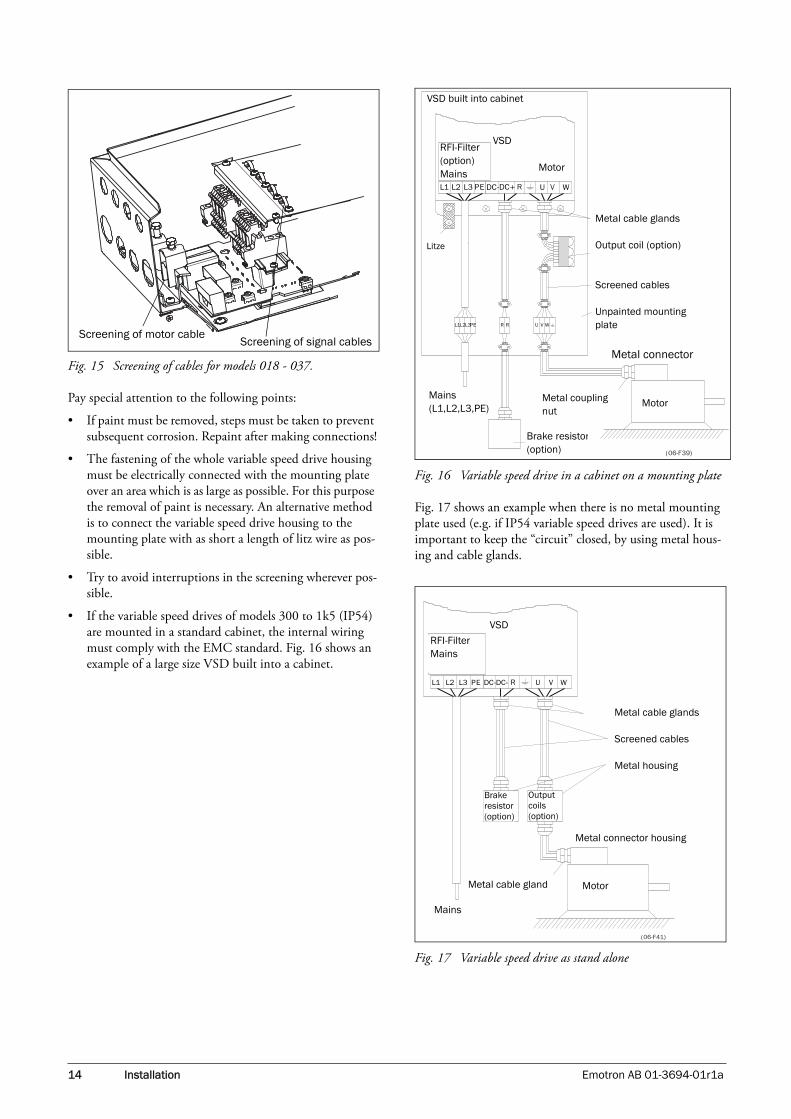
Fig. 15 Screening of cables for models 018 - 037.
Pay special attention to the following points:
• If paint must be removed, steps must be taken to prevent subsequent corrosion. Repaint after making connections!
• The fastening of the whole variable speed drive housing must be electrically connected with the mounting plate over an area which is as large as possible. For this purpose the removal of paint is necessary. An alternative method is to connect the variable speed drive housing to the mounting plate with as short a length of litz wire as pos-sible.
• Try to avoid interruptions in the screening wherever pos-sible.
• If the variable speed drives of models 300 to 1k5 (IP54) are mounted in a standard cabinet, the internal wiring must comply with the EMC standard. Fig. 16 shows an example of a large size VSD built into a cabinet.
Fig. 16 Variable speed drive in a cabinet on a mounting plate
Fig. 17 shows an example when there is no metal mounting plate used (e.g. if IP54 variable speed drives are used). It is important to keep the “circuit” closed, by using metal hous-ing and cable glands.
Fig. 17 Variable speed drive as stand alone
Screening of motor cableScreening of signal cables
VSD built into cabinet
VSDRFI-Filter (option)Mains
Metal cable glands
Output coil (option)
Screened cables
Unpainted mounting plate
Metal connector
MotorMetal coupling nut
Brake resistor(option)
Mains(L1,L2,L3,PE)
Litze
Motor
VSD
RFI-Filter Mains
Metal cable glands
Screened cables
Metal housing
Brake resistor (option)
Output coils (option)
Metal connector housing
MotorMetal cable gland
Mains

Emotron AB 01-3694-01r1a Installation 15
Placing of motor cablesKeep the motor cables as far away from other cables as possi-ble, especially from control signals. The minimum distance between motor cables and control cables is 30 cm.
Avoid placing the motor cables in parallel with other cables.
The power cables should cross other cables at an angle of 90°.
Long motor cablesIf the connection to the motor is longer than 100 m (40 m for models 003-013), it is possible that capacitive current peaks will cause tripping at overcurrent. Using output coils can prevent this. Contact the supplier for appropriate coils.
Switching in motor cablesSwitching in the motor connections is not advisable. In the event that it cannot be avoided (e.g. emergency or mainte-nance switches) only switch if the current is zero. If this is not done, the VSD can trip as a result of current peaks.
3.2.2 Mains cablesDimension the mains and motor cables according to local regulations. The cable must be able to carry the VSD load current.
Requirements for selecting mains cables• The mains cables do not need to be screened.
• Use heat-resistant cables, +60°C or higher.
• Dimension the cables and fuses in accordance with thenominal output current of the motor. See table 42, page158.
• The litz connection is only necessary if the mountingplate is painted. All the variable speed drives have anunpainted back side and are therefore suitable formounting on an unpainted mounting plate.
Connect the mains cables according to Fig. 18 The VSD has a RFI mains filter that complies with the 2nd environment standard.
Fig. 18 Mains and motor connections
3.3 Cable specifications
3.4 Stripping lengthsFig. 19 indicates the recommended stripping lengths for motor and mains cables.
L2 L3 PEL1 U V WRDC+
DC-
OPTION
Table 6 Mains and motor connection
L1,L2,L3PE
Mains supply, 3 -phaseSafety earth (protected earth)
U, V, WMotor earthMotor output, 3-phase
(DC-),DC+,RBrake resistor, DC-link connections (optional)
NOTE: The Brake and DC-link Terminals are only fitted if the Brake Chopper Option is built-in.
WARNING: The Brake Resistor must be connected between terminals DC+ and R.
WARNING: In order to work safely, the mains earth must be connected to PE and the motor earth to .
Table 7 Cable specifications
Cable Cable specification
MainsPower cable suitable for fixed installation for the voltage used.
MotorPower cable with concentric protection wire or with compact low-impedance shield for the voltage used.
ControlControl cable with low-impedance shield, screened.
Table 8 Stripping lengths for mains and motor cables
Model
Mains cable Motor cable
a (mm)
b (mm)
a (mm)
b (mm)
c (mm)
003–013 60 8 60 8 31
018–037 115 12 115 12 32
046–073 130 11 130 11 34
090-175 160 16 160 16 41
210–250 170 24 170 24 46
16 Installation Emotron AB 01-3694-01r1a
Fig. 19 Stripping lengths for cables
3.4.1 Dimension of cables and fusesPlease refer to the chapter Technical data, section 14.7, page 158
3.4.2 Tightening torque for mains and motor cables
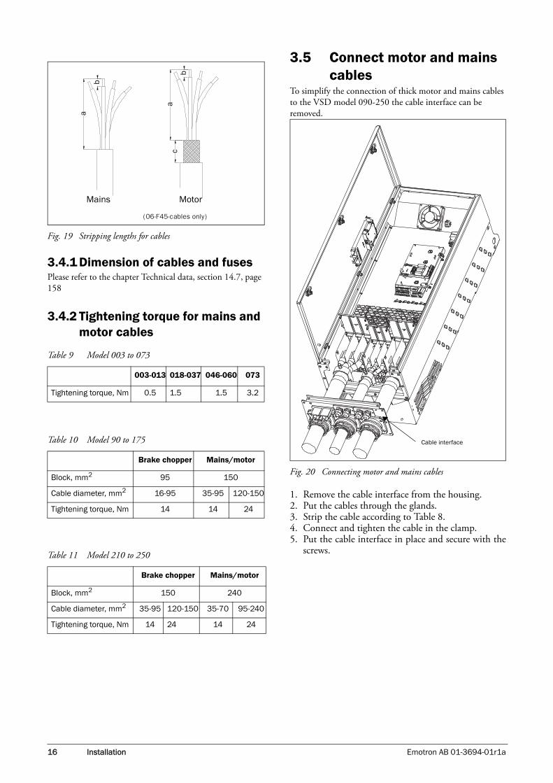
3.5 Connect motor and mains cables
To simplify the connection of thick motor and mains cables to the VSD model 090-250 the cable interface can be removed.
Fig. 20 Connecting motor and mains cables
1. Remove the cable interface from the housing.2. Put the cables through the glands.3. Strip the cable according to Table 8.4. Connect and tighten the cable in the clamp.5. Put the cable interface in place and secure with the
screws.
Table 9 Model 003 to 073
003-013 018-037 046-060 073
Tightening torque, Nm 0.5 1.5 1.5 3.2
Table 10 Model 90 to 175
Brake chopper Mains/motor
Block, mm2 95 150
Cable diameter, mm2 16-95 35-95 120-150
Tightening torque, Nm 14 14 24
Table 11 Model 210 to 250
Brake chopper Mains/motor
Block, mm2 150 240
Cable diameter, mm2 35-95 120-150 35-70 95-240
Tightening torque, Nm 14 24 14 24
(06-F45-cables only)
MotorMains
Cable interface

Emotron AB 01-3694-01r1a Installation 17
3.6 Thermal protection on the motor
Standard motors are normally fitted with an internal fan. The cooling capacity of this built-in fan is dependent on the frequency of the motor. At low frequency, the cooling capac-ity will be insufficient for nominal loads. Please contact the motor supplier for the cooling characteristics of the motor at lower frequency.
Motor thermistors offer better thermal protection for the motor. Depending on the type of motor thermistor fitted, the optional PTC input may be used. The motor thermistor gives a thermal protection independent of the speed of the motor, thus of the speed of the motor fan. See the functions, Motor I2t type [231] and Motor I2t current [232].
3.7 Motors in parallelIt is possible to have motors in parallel as long as the total current does not exceed the nominal value of the VSD. The following has to be taken into account when setting the motor data:
WARNING: Depending on the cooling characteristics of the motor, the application, the speed and the load, it may be necessary to use forced cooling on the motor.
Menu [221] Motor Voltage:
The motors in parallel must have the same motor voltage.
Menu [222] Motor Frequency:
The motors in parallel must have the same motor frequency.
Menu [223] Motor Power:
Add the motor power values for the motors in parallel.
Menu [224] Motor Current:
Add the current for the motors in parallel.
Menu [225] Motor Speed:
Set the average speed for the motors in parallel.
Menu [227] Motor Cos PHI:
Set the average Cos PHI value for the motors in parallel.

18 Installation Emotron AB 01-3694-01r1a

Emotron AB 01-3694-01r1a Control Connections 19
4. Control Connections
4.1 Control boardFig. 21 shows the layout of the control board which is where the parts most important to the user are located. Although the control board is galvanically isolated from the mains, for safety reasons do not make changes while the mains supply is on!
Fig. 21 Control board layout
WARNING: Always switch off the mains voltage and wait at least 5 minutes to allow the buffer capacitors to discharge before connecting the control signals or changing position of the switches.
X8
X2
X3
X1
S2S1
PE
S3 S4
X5
X4
X6 X7
UI I UUI I U
1
12 22
11
41 42 43
31 32 33 51 52
Relay outputs
Control signals
Switches
Option
Control Panel
Communication

20 Control Connections Emotron AB 01-3694-01r1a
4.2 Terminal connectionsThe terminal strip for connecting the control signals is accessible after opening the front panel.
The table describes the default functions for the signals. The inputs and outputs are programmable for other functions as described in chapter 11. page 59. For signal specifications refer to chapter 14. page 153.
NOTE: The maximum total combined current for outputs 11, 20 and 21 is 100mA.
Table 12 Control signals
Terminal Name Function (Default)
Outputs
1 +10 V +10 VDC supply voltage
6 -10 V -10 VDC supply voltage
7 Common Signal ground
11 +24 V +24 VDC supply voltage
12 Common Signal ground
15 Common Signal ground
Digital inputs
8 DigIn 1 RunL
9 DigIn 2 RunR
10 DigIn 3 Off
16 DigIn 4 Off
17 DigIn 5 Off
18 DigIn 6 Off
19 DigIn 7 Off
22 DigIn 8 RESET
Digital outputs
20 DigOut 1 Ready
21 DigOut 2 Brake
Analogue inputs
2 AnIn 1 Process Ref
3 AnIn 2 Off
4 AnIn 3 Off
5 AnIn 4 Off
Analogue outputs
13 Speed Min speed to max speed
14 Torque 0 to max torque
Relay outputs
31 N/C 1Relay 1 outputTrip, active when the VSD is in a TRIP condition.
32 COM 1
33 N/O 1
41 N/C 2Relay 2 outputRun, active when the VSD is started.
42 COM 2
43 N/O 2
51 COM 3 Relay 3 output Off52 N/O 3
NOTE: N/C is opened when the relay is active and N/O is closed when the relay is active.
Table 12 Control signals
Terminal Name Function (Default)

Emotron AB 01-3694-01r1a Control Connections 21
4.3 Connection exampleFig. 22 gives an overall view of a VSD connection example.
Fig. 22 Connection example
NG_06-F27
L1
L3
L1L2
PE
123
UVW
DC+
R
313233
41
13211420
12
21
6789
10
18
11151617
22
19
5152
4243
54
PREV NEXT ESC
ENTER
RESET
LOC/REM
RFI-filter
+10 VDC
AnIn 1
AnIn 2
AnIn 3
AnIn 4
-10 VDC
Common
DigIn 1:RunL
DigIn 2:RunR
DigIn3
+24 VDC
Common
DigIn 4
DigIn 5
DigIn 6
DigIn 7
DigIn 8
Common
AnOut 1
AnOut 2
DigOut 1
DigOut 2
Motor
Fieldbus Optionor PC Option Board
PC/FBO Options
0 - 10 V4 - 20 mA

22 Control Connections Emotron AB 01-3694-01r1a
4.4 Inputs configurationwith the switches
The switches S1 to S4 are used to set the input configuration for the 4 analogue inputs AnIn1, AnIn2, AnIn3 and AnIn4 as described in table 13. See Fig. 21 for the location of the switches.
4.5 Connecting the Control Signals
4.5.1 CablesThe standard control signal connections are suitable for stranded flexible wire up to 1.5 mm2 and for solid wire up to 2.5 mm2.
Fig. 23 Connecting the control signals
Table 13 Switch settings
Input Type Switch
AnIn10-10 V (default) S1
0-20 mA S1
AnIn20 -10 V (default) S2
0-20 mA S2
AnIn30 -10 V (default) S3
0-20 mA S3
AnIn40 -10 V (default) S4
0-20 mA S4
NOTE: the 2 analogue outputs AnOut 1 and AnOut 2 can be configured via the software. See menu [530] section 11.6.3, page 114
UI
UI
UI
UI
UI
UI
UI
UI
NOTE: The screening of control signal cables is necessary to comply with the immunity levels given in the EMC Directive (it reduces the noise level).
NOTE: Control cables must be separated from motor and mains cables.
Make sure that the control cables do not make contact with electrical components in the device.
Control signals

Emotron AB 01-3694-01r1a Control Connections 23
4.5.2 Types of control signalsAlways make a distinction between the different types of sig-nals. Because the different types of signals can adversely affect each other, use a separate cable for each type. This is often more practical because, for example, the cable from a pressure sensor may be connected directly to the variable speed drive.
We can distinguish between the following types of control signals:
Analogue inputsVoltage or current signals, (0-10 V, 0/4-20 mA) normally used as control signals for speed, torque and PID feedback signals.
Analogue outputsVoltage or current signals, (0-10 V, 0/4-20 mA) which change slowly or only occasionally in value. In general, these are control or measurement signals.
DigitalVoltage or current signals (0-10 V, 0-24 V, 0/4-20 mA) which can have only two values (high or low) and only occa-sionally change in value.
DataUsually voltage signals (0-5 V, 0-10 V) which change rapidly and at a high frequency, generally data signals such as RS232, RS485, Profibus, etc.
RelayRelay contacts (0-250 VAC) can switch highly inductive loads (auxiliary relay, lamp, valve, brake, etc.).
Example: The relay output from a variable speed drive which controls an auxiliary relay can, at the moment of switching, form a source of interference (emission) for a measurement signal from, for example, a pressure sensor. Therefore it is advised to separate wiring and screening to reduce disturbances.
4.5.3 ScreeningFor all signal cables the best results are obtained if the screening is connected to both ends: the VSD side and the at the source (e.g. PLC, or computer). See Fig. 24.
It is strongly recommended that the signal cables be allowed to cross mains and motor cables at a 90° angle. Do not let the signal cable go in parallel with the mains and motor cable.
4.5.4 Single-ended or double-ended connection?
In principle, the same measures applied to power supply cables must be applied to all control signal cables, in accord-ance with the EMC-Directives.
For all signal cables as mentioned in section 4.5.2 the best results are obtained if the screening is connected to both ends. See Fig. 24.
Fig. 24 Electro Magnetic (EM) screening of control signal cables.
4.5.5 Current signals ((0)4-20 mA)A current signal like (0)4-20 mA is less sensitive to distur-bances than a 0-10 V signal, because it is connected to an input which has a lower impedance (250 Ω) than a voltage signal (20 kΩ). It is therefore strongly advised to use current control signals if the cables are longer than a few metres.
Signal type
Maximum wire sizeTightening
torqueCable type
Analogue Rigid cable: 0.14-2.5 mm2
Flexible cable: 0.14-1.5 mm2
Cable with ferrule: 0.25-1.5 mm2
0.5 Nm
Screened
Digital Screened
Data Screened
Relay Not screened
NOTE: Each installation must be examined carefully before applying the proper EMC measurements.
NOTE: Each installation must be examined carefully before applying the proper EMC measurements.
Control board
Pressure sensor(example)
External control (e.g. in metal housing)
Control consol

24 Control Connections Emotron AB 01-3694-01r1a
4.5.6 Twisted cablesAnalogue and digital signals are less sensitive to interference if the cables carrying them are “twisted”. This is certainly to be recommended if screening cannot be used. By twisting the wires the exposed areas are minimised. This means that in the current circuit for any possible High Frequency (HF) interference fields, no voltage can be induced. For a PLC it is therefore important that the return wire remains in prox-imity to the signal wire. It is important that the pair of wires is fully twisted over 360°.
4.6 Connecting optionsThe option cards are connected by the optional connectors X4 or X5 on the control board see Fig. 21, page 19 and mounted above or beside the control board depending on the version and size of the VSD. The inputs and outputs of the option cards are connected in the same way as other con-trol signals.

Emotron AB 01-3694-01r1a Getting Started 25
5. Getting Started
This chapter is a step by step guide that will show you the quickest way to get the motor shaft turning. We will show you two examples, remote control and manual control.
We assume that the VSD is mounted on a wall or in a cabi-net as in the chapter 2. page 9.
First there is general information of how to connect mains, motor and control cables. The next section describes how to use the function keys on the control panel. The subsequent examples covering remote control and manual control describe how to program/set the motor data and run the VSD and motor.
5.1 Connect the mains and motor cables
Dimension the mains and motor cables according to local regulations. The cablse must be able to carry the VSD load current.
5.1.1 Mains cables1. Connect the mains cables as in Fig. 25. The VSD has a
RFI mains filter that complies with the 2nd environment standard.
5.1.2 Motor cables2. Connect the motor cables as in Fig. 25. To comply with
the EMC Directive you have to use screened cables and the motor cable screen has to be connected on both sides: to the housing of the motor and the housing of the VSD.
Fig. 25 Connection of mains and motor cables
WARNING: In order to work safely the mains earth must be connected to PE and the motor earth to .
5.2 Connect control cablesHere you will make up the minimum wiring for starting. In this example the motor/VSD will run with right rotation.
To comply with the EMC standard, use screened control cables with plaited flexible wire up to 1.5 mm2 or solid wire up to 2.5 mm2.
3. Connect a reference value between terminals 7 (Com-mon) and 2 (AnIn 1) as in Fig. 26.
4. Connect an external start button between terminal 11 (+24 VDC) and 8 (DigIn1, RUN) as inFig. 26.
Fig. 26 Wiring
Table 14 Mains and motor connection
L1,L2,L3PE
Mains supply, 3 -phaseSafety earth
U, V, WMotor earthMotor output, 3-phase
L2 L3 PEL1 U V WRDC+
DC-
X2
X3
X1
PE
112
2211
41
42
43
31
32
33
51
52
2
3
4
5
6
7
8
9
10
13
14
15
16
17
18
19
20
21
Start
Reference0-10 V

26 Getting Started Emotron AB 01-3694-01r1a
5.3 Using the function keys
Fig. 27 Example of menu navigation when entering motor voltage
5.4 Remote controlIn this exampel external signals are used to control the VSD/motor.
A standard 4-pole motor for 400 V, an external start button and a reference value will also be used.
5.4.1 Switch on the mainsClose the door to the VSD. Once the mains is switched on, the internal fan in the VSD will run for 5 seconds.
5.4.2 Set the Motor DataEnter correct motor data for the connected motor. The motor data is used in the calculation of complete operational data in the VSD.
Change settings using the keys on the control panel. For fur-ther information about the control panel and menu struc-ture, see the chapter 9. page 49.
Menu [100], Preferred View is displayed when started.
1. Press to display menu [200], Main Setup.
2. Press and then to display menu [220], Motor Data.
3. Press to display menu [221] and set motor voltage.
4. Change the value using the and keys. Confirm with .
5. Set motor frequency [222].
6. Set motor power [223].
7. Set motor current [224].
8. Set motor speed [225].
9. Set power factor (cos ϕ) [227].
10. [229] Motor ID run: Choose Short, confirm with ENTER and give start command .
The VSD will now measure some motor parameters. The motor makes some beeping sounds but does not rotate. When the ID run is finished after about one minute ("Test Run OK!" is displayed), press to con-tinue.
11. Use AnIn1 as input for the reference value. The default range is 0-10 V. If you need a 4-20mA reference value, change switch (S1) on control board and set [512] Anln 1 Set-up to 2-10V/4-20mA.
12. Switch off power supply.13. Connect digital and analogue inputs/outputs as in Fig.
26. 14. Ready! 15. Switch on power supply.
5.4.3 Run the VSDNow the installation is finished, and you can press the start button to start the motor.
This example will show that the main connections are OK and that the motor will run with the load.
step to lower menu level or confirm changed setting
step to higher menu level or ignore changed setting
step to next menu on the same level
step to previous menu on the same level
increase value or change selection
decrease value or change selection
100 200 300
220
221
210
PREV
ENTERENTER
NEXT
ESCESCENTERENTER
ENTERENTER
NEXT
ENTER
ESC
NEXTNEXT
PREVPREV
NEXT
ENTERENTER NEXT
ENTERENTER
ENTERENTER
RESET

Emotron AB 01-3694-01r1a Getting Started 27
5.5 Local controlManual control via the control panel can be used to carry out a test run.
Use a 400 V motor and the control panel.
5.5.1 Switch on the mainsClose the door to the VSD. Once the mains is switched on, the VSD is started and the internal fan will run for 5 sec-onds.
5.5.2 Select manual controlMenu [100], Preferred View is displayed when started.
1. Press to display menu [200], Main Setup.
2. Press to display menu [210], Operation.
3. Press to display menu [214], Reference Control.
4. Select Keyboard using the key and press to con-firm.
5. Press to get to menu [215], Run/Stop Control.
6. Select Keyboard using the key and press to con-firm.
7. Press to get to previous menu level and then to display menu [220], Motor Data.
5.5.3 Set the Motor DataEnter correct motor data for the connected motor.
8. Press to display menu [221].
9. Change the value using the and keys. Confirm with .
10. Press to display menu [222].
11. Repeat step 9 and 10 until all motor data is entered.
12. Press twice and then to display menu [100], Pre-ferred View.
5.5.4 Enter a Reference ValueEnter a reference value.
13. Press until menu [310], Set/View reference value is displayed.
14. Use the + and - keys to enter 10 Hz. We select a low value to check the rotation direction without damaging the motor.
5.5.5 Run the VSDPress the RUN L or RUN R keys on the control panel to run the motor.
This example will show that the main connections are OK and that the motor will run with the load.
NEXT
ENTERENTER
NEXT
ENTERENTER
NEXT
ENTERENTER
ESCESC NEXT
ENTERENTER
ENTERENTER
NEXT
ESCESC PREV
NEXT

28 Getting Started Emotron AB 01-3694-01r1a

Emotron AB 01-3694-01r1a Applications 29
6. Applications
This chapter contains tables giving an overview of many dif-ferent applications/duties in which it is suitable to use varia-ble speed drives from Emotron. Further on you will find
application examples of the most common applications and solutions.
6.1 Application overview
6.1.1Pumps
6.1.2Fans
Challenge Emotron FDU solution Menu
High start currents require larger fuses and cables. Cause stress on equipment and higher energy cost.
Torque control reduces start current. Same fuses can be used as those required for the motor.
331–336, 351
Dry-running, cavitation and overheating damage the pump and cause downtime.
Pump Curve Protection detects deviation. Sends warning or activates safety stop.
411–419, 41C– 1C9
Sludge sticks to impeller when pump has been run-ning at low speed or been stationary for a while. Reduces the pump’s efficiency.
Automatic pump rinsing function: pump is set to run at full speed at certain intervals, then return to normal speed.
362–368, 560, 640
Motor runs at same speed despite varying demands in pressure/flow. Energy is lost and equipment stressed.
PID continuously adapts pressure/flow to the level required. Sleep function activated when none is needed.
320, 380, 342, 354
Process inefficiency due to e.g. a blocked pipe, a valve not fully opened or a worn impeller.
Pump Curve Protection detects deviation. Warn-ing is sent or safety stop activated.
411–419, 41C–41C9
Water hammer damages the pump when stopped. Mechanical stress on pipes, valves, gaskets, seals.
Smooth linear stops protect the equipment. Elimi-nates need for costly motorized valves.
331–336
Challenge Emotron FDU solution Menu
High start currents require larger fuses and cables. Causs stress on equipment and higher energy cost.
Torque control reduces start current. Same fuses can be used as those required for the motor.
331–336, 351
Starting a fan rotating in the wrong direction can be critical, e.g. a tunnel fan in event of a fire.
Fan is started at low speed to ensure correct direction and proper function.
219, 341
Draft causes turned off fan to rotate the wrong way. Starting causes high current peaks and mechanical stress.
Motor is gradually slowed to complete stop before starting. Avoids blown fuses and breakdown.
219, 33A, 335
Regulating pressure/flow with dampers causes high energy consumption and equipment wear.
Automatic regulation of pressure/flow with motor speed gives more exact control.
321, 354
Motor runs at same speed despite varying demands in pressure/flow. Energy is lost and equipment stressed.
PID continuously adapts to the level required. Sleep function is activated when none is needed.
320, 380, 342, 354
Process inefficiency due to e.g. a blocked filter, a damper not fully opened or a worn belt.
Load Curve Protection detects deviation. Warning is sent or safety stop activated.
411–419, 41C–41C9
30 Applications Emotron AB 01-3694-01r1a
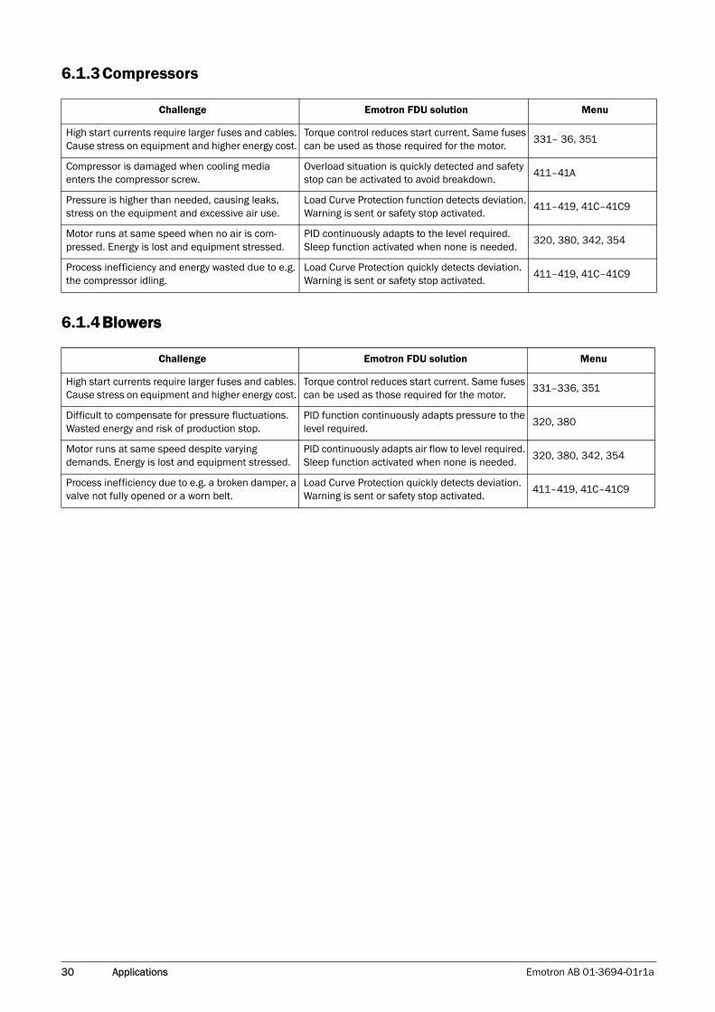
6.1.3Compressors
6.1.4Blowers
Challenge Emotron FDU solution Menu
High start currents require larger fuses and cables. Cause stress on equipment and higher energy cost.
Torque control reduces start current. Same fuses can be used as those required for the motor.
331– 36, 351
Compressor is damaged when cooling media enters the compressor screw.
Overload situation is quickly detected and safety stop can be activated to avoid breakdown.
411–41A
Pressure is higher than needed, causing leaks, stress on the equipment and excessive air use.
Load Curve Protection function detects deviation. Warning is sent or safety stop activated.
411–419, 41C–41C9
Motor runs at same speed when no air is com-pressed. Energy is lost and equipment stressed.
PID continuously adapts to the level required. Sleep function activated when none is needed.
320, 380, 342, 354
Process inefficiency and energy wasted due to e.g. the compressor idling.
Load Curve Protection quickly detects deviation. Warning is sent or safety stop activated.
411–419, 41C–41C9
Challenge Emotron FDU solution Menu
High start currents require larger fuses and cables. Cause stress on equipment and higher energy cost.
Torque control reduces start current. Same fuses can be used as those required for the motor.
331–336, 351
Difficult to compensate for pressure fluctuations. Wasted energy and risk of production stop.
PID function continuously adapts pressure to the level required.
320, 380
Motor runs at same speed despite varying demands. Energy is lost and equipment stressed.
PID continuously adapts air flow to level required. Sleep function activated when none is needed.
320, 380, 342, 354
Process inefficiency due to e.g. a broken damper, a valve not fully opened or a worn belt.
Load Curve Protection quickly detects deviation. Warning is sent or safety stop activated.
411–419, 41C–41C9
Emotron AB 01-3694-01r1a Main Features 31
7. Main Features
This chapter contains descriptions of the main features of the VSD.
7.1 Parameter setsParameter sets are used if an application requires different settings for different modes. For example, a machine can be used for producing different products and thus requires two or more maximum speeds and acceleration/deceleration times. With the four parameter sets different control options can be configured with respect to quickly changing the behaviour of the VSD. It is possible to adapt the VSD online to altered machine behaviour. This is based on the fact that at any desired moment any one of the four parame-ter sets can be activated during Run or Stop, via the digital inputs or the control panel and menu [241].
Each parameter set can be selected externally via a digital input. Parameter sets can be changed during operation and stored in the control panel.
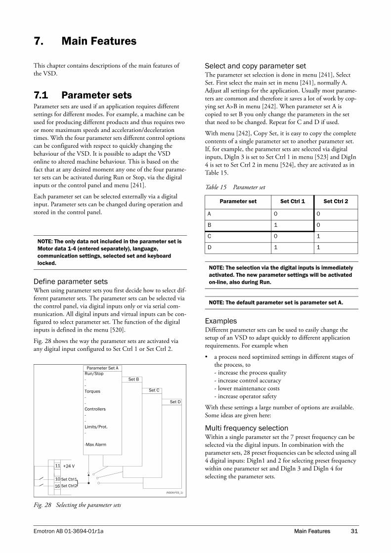
Define parameter setsWhen using parameter sets you first decide how to select dif-ferent parameter sets. The parameter sets can be selected via the control panel, via digital inputs only or via serial com-munication. All digital inputs and virtual inputs can be con-figured to select parameter set. The function of the digital inputs is defined in the menu [520].
Fig. 28 shows the way the parameter sets are activated via any digital input configured to Set Ctrl 1 or Set Ctrl 2.
Fig. 28 Selecting the parameter sets
Select and copy parameter setThe parameter set selection is done in menu [241], Select Set. First select the main set in menu [241], normally A. Adjust all settings for the application. Usually most parame-ters are common and therefore it saves a lot of work by cop-ying set A>B in menu [242]. When parameter set A is copied to set B you only change the parameters in the set that need to be changed. Repeat for C and D if used.
With menu [242], Copy Set, it is easy to copy the complete contents of a single parameter set to another parameter set. If, for example, the parameter sets are selected via digital inputs, DigIn 3 is set to Set Ctrl 1 in menu [523] and DigIn 4 is set to Set Ctrl 2 in menu [524], they are activated as in Table 15.
ExamplesDifferent parameter sets can be used to easily change the setup of an VSD to adapt quickly to different application requirements. For example when
• a process need soptimized settings in different stages of the process, to- increase the process quality- increase control accuracy- lower maintenance costs- increase operator safety
With these settings a large number of options are available. Some ideas are given here:
Multi frequency selectionWithin a single parameter set the 7 preset frequency can be selected via the digital inputs. In combination with the parameter sets, 28 preset frequencies can be selected using all 4 digital inputs: DigIn1 and 2 for selecting preset frequency within one parameter set and DigIn 3 and DigIn 4 for selecting the parameter sets.
NOTE: The only data not included in the parameter set is Motor data 1-4 (entered separately), language, communication settings, selected set and keyboard locked.
{(NG06-F03_1)
Run/Stop--Torques--Controllers--Limits/Prot.-
-Max Alarm
Parameter Set A
Set B
Set C
Set D
11
10
16
Set Ctrl1
Set Ctrl2
+24 V
Table 15 Parameter set
Parameter set Set Ctrl 1 Set Ctrl 2
A 0 0
B 1 0
C 0 1
D 1 1
NOTE: The selection via the digital inputs is immediately activated. The new parameter settings will be activated on-line, also during Run.
NOTE: The default parameter set is parameter set A.

32 Main Features Emotron AB 01-3694-01r1a
Bottling machine with 3 different productsUse 3 parameter sets for 3 different Jog frequencies when the machine needs to be set up. The 4th parameter set can be used for “normal” remote control when the machine is run-ning at full production.
Manual - automatic controlIf in an application something is filled up manually and then the level is automatically controlled using PID regulation, this is solved using one parameter set for the manual control and one for the automatic control
7.1.1 One motor and one parameter set
This is the most common application for pumps and fans.
Once default motor M1 and parameter set A have been selected:
1. Enter the settings for motor data.
2. Enter the settings for other parameters e.g. inputs and outputs
7.1.2 One motor and two parameter sets
This application is useful if you for example have a machine running at two different speeds for different products.
Once default motor M1 is selected:
1. Select parameter set A in menu [241].
2. Enter motor data in menu [220].
3. Enter the settings for other parameters e.g. inputs and outputs.
4. If there are only minor differences between the settings in the parameter sets, you can copy parameter set A to parameter set B, menu [242].
5. Enter the settings for parameters e.g. inputs and outputs.
7.1.3 Two motors and two parameter sets
This is useful if you have a machine with two motors that can not run at the same time, such as a cable winding machine that lifts up the reel with one motor and then turns the wheel with the other motor.
One motor must stop before changing to an other motor.
1. Select parameter set A in menu [241].
2. Select motor M1 in menu [212].
3. Enter motor data and settings for other parameters e.g. inputs and outputs.
4. Select parameter set B in menu [241].
5. Select M2 in menu [212].
6. Enter motor data and settings for other parameters e.g. inputs and outputs.
7.1.4 Autoreset at tripFor several non-critical application-related failure condi-tions, it is possible to automatically generate a reset com-mand to overcome the fault condition. The selection can be made in menu [250]. In this menu the maximum number of automatically generated restarts allowed can be set, see menu [251], after this the VSD will stay in fault condition because external assistance is required.
ExampleThe motor is protected by an internal protection for thermal overload. When this protection is activated, the VSD should wait until the motor is cooled down enough before resuming normal operation. When this problem occurs three times in a short period of time, external assistance is required.
The following settings should be applied:
• Insert maximum number of restarts; set menu [251] to 3.
• Activate Motor I2t to be automatically reset; set menu [25A] to 300 s.
• Set relay 1, menu [551] to AutoRst Trip; a signal will be available when the maximum number of restarts is reached and the VSD stays in fault condition.
7.1.5 Reference priorityThe active speed reference signal can be programmed from several sources and functions. The table below shows the priority of the different functions with regards to the speed reference.
Note: Do not change motor data.
Table 16 Reference priority
Jog Mode
Preset Reference
Motor Pot Ref. Signal
On/Off On/Off On/Off Option cards
On On/Off On/Off Jog Ref
Off On On/Off Preset Ref
Off Off On Motor pot commands

Emotron AB 01-3694-01r1a Main Features 33
7.1.6 Preset referencesThe VSD is able to select fixed speeds via the control of dig-ital inputs. This can be used for situations where the required motor speed needs to be adapted to fixed values, according to certain process conditions. Up to 7 preset refer-ences can be set for each parameter set, which can be selected via all digital inputs that are set to Preset Ctrl1, Pre-set Ctrl2 or Preset Ctrl3. The amount digital inputs used that are set to Preset Ctrl determines the number of Preset References available; using 1 input gives 2 speeds, using 2 inputs gives 4 speeds and using 3 inputs gives 8 speeds.
ExampleThe use of four fixed speeds, at 50 / 100 / 300 / 800 rpm, requires the following settings:
• Set DigIn 5 as first selection input; set [525] to Preset Ctrl1.
• Set DigIn 6 as second selection input; set [526] to Preset Ctrl2.
• Set menu [341], Min Speed to 50 rpm.
• Set menu [362], Preset Ref 1 to 100 rpm.
• Set menu [363], Preset Ref 2 to 300 rpm.
• Set menu [364], Preset Ref 3 to 800 rpm.
With these settings, the VSD switched on and a RUN com-mand given, the speed will be:
• 50 rpm, when both DigIn 5 and DigIn 6 are low.
• 100 rpm, when DigIn 5 is high and DigIn 6 is low.
• 300 rpm, when DigIn 5 is low and DigIn 6 is high.
• 800 rpm, when both DigIn 5 and DigIn 6 are high.
7.2 Remote control functionsOperation of the Run/Stop/Enable/Reset functions
As default, all the run/stop/reset related commands are pro-grammed for remote operation via the inputs on the termi-nal strip (terminals 1-22) on the control board. With the function Run/Stp Ctrl [215] and Reset Control [216], this can be selected for keyboard or serial communication con-trol.
Default settings of the Run/Stop/Enable/Reset functionsThe default settings are shown in Fig. 29. In this example the VSD is started and stopped with DigIn 1 and a reset after trip can be given with DigIn 4.
Fig. 29 Default setting Run/Reset commands
The inputs are default set for level-control. The rotation is determined by the rotation set according to the active parameter set.
NOTE: The examples in this paragraph do not cover all possibilities. Only the most relevant combinations are given. The starting point is always the default setting (factory) of the VSD.
XX1
PE
112
2211
2
3
4
5
6
7
8
9
10
13
14
15
16
17
18
19
20
21
Run
Reset+24 V

34 Main Features Emotron AB 01-3694-01r1a
Enable and Stop functionsBoth functions can be used separately or simultaneously. The choice of which function is to be used depends on the application and the control mode of the inputs (Level/Edge [21A]).
EnableInput must be active (HI) to allow any Run signal. If the input is made LOW, the output of the VSD is immediately disabled and the motor will coast.
StopIf the input is low then the VSD will stop according to the selected stop mode set in menu [33B] Stop Mode. Fig. 30 shows the function of the Enable and the Stop input and the Stop Mode=Decel [33B].
To run the input must be HI.
Fig. 30 Functionality of the Stop and Enable input
Reset and Autoreset operationIf the VSD is in Stop Mode due to a trip condition, the VSD can be remotely reset by a pulse (“low” to “high” tran-sition) on the Reset input, default on DigIn 4. Depending on the selected control method, a restart takes place as fol-lows:
Level-controlIf the Run inputs remain in their position the VSD will start immediately after the Reset command is given.
Edge-controlAfter the Reset command is given a new Run command must be applied to start the VSD again.
Autoreset is enabled if the Reset input is continuously active. The Autoreset functions are programmed in menu Autoreset [250].
Run Inputs Level-controlled.The inputs are set as default for level-control. This means that an input is activated by making the input continuously “High”. This method is commonly used if, for example, PLCs are used to operate the VSD.
The examples given in this and the following paragraphs fol-low the input selection shown in Fig. 31.
Fig. 31 Example of wiring for Run/Stop/Enable/Reset inputs
The Enable input must be continuously active in order to accept any run-right or run-left command. If both RunR and RunL inputs are active, then the VSD stops according to the selected Stop Mode. Fig. 32 gives an example of a pos-sible sequence.
NOTE: In the Edge mode, at least one digital input must be programmed to “stop”, because the Run commands are then only able to start the VSD.
CAUTION: If the Enable function is not programmed to a digital input, it is considered to be active internally.
NOTE: The Stop Mode=Coast [33B] will give the same behaviour as the Enable input.
!
(06-F104_NG)
t
t
STOP(STOP=DECEL)
OUTPUTSPEED
ENABLE
OUTPUTSPEED
(or if Spinstart is selected)
NOTE: If the control commands are programmed for Keyboard control, Autoreset is not possible.
CAUTION: Level-controlled inputs DO NOT comply with the Machine Directive, if the inputs are directly used to start and stop the machine.!
XX1
PE
112
2211
2
3
4
5
6
7
8
9
10
13
14
15
16
17
18
19
20
21
Stop
Reset+24 V
RunR
RunLEnable

Emotron AB 01-3694-01r1a Main Features 35
Fig. 32 Input and output status for level-control
Run Inputs Edge-controlledMenu [21A] Start signal Level/Edge must be set to Edge to activate edge control. This means that an input is activated by a “low” to “high” transition or vice versa.
See Fig. 31. The Enable and Stop input must be active con-tinuously in order to accept any run-right or run-left com-mand. The last edge (RunR or RunL) is valid. Fig. 33 gives an example of a possible sequence.
Fig. 33 Input and output status for edge-control
7.3 Performing an Identification Run
To get the optimum performance out of your VSD/motor combination, the VSD must measure the electrical parame-ters (resistance of stator winding, etc.) of the connected motor.
It is recommended that the extended ID run be used before the motor is installed in the application.
If this is not possible, the short ID run should be used.
NOTE: Edge-controlled inputs comply with the Machine Directive (see chapter EMC and Machine Directive), if the inputs are directly used for starting and stopping the machine.
(06-F103new_1)
INPUTS
OUTPUTSTATUS
ENABLE
STOP
RUN R
RUN L
Right rotation
Left rotation
Standstill
WARNING: During the extended ID RUN, the motor will rotate. Take safety measures to avoid unforeseen dangerous situations.
(06-F94new_1)
INPUTS
ENABLE
STOP
RUN R
RUN L
OUTPUTSTATUS
Right rotation
Left rotation
Standstill

36 Main Features Emotron AB 01-3694-01r1a
7.4 Using the Control Panel Memory
Data can be copied from the VSD to the memory in the control panel and vice versa. To copy all data from the VSD to the control panel, select Copy to CP[244], Copy to CP.
To copy data from the control panel to the VSD, enter the menu [245], Load from CP and select what you want to copy.
The memory in the control panel is useful in applications with VSDs without a control panel and in applications where several variable speed drives have the same setup. It can also be used for temporary storage of settings. Use a con-trol panel to upload the settings from one VSD and then move the control panel to another VSD and download the settings.
Fig. 34 Copy and load parameters between VSD and control panel
7.5 Load Monitor and Process Protection [400]
7.5.1 Load Monitor [410]The monitor functions enable the VSD to be used as a load monitor. Load monitors are used to protect machines and processes against mechanical overload and underload, such as a conveyer belt or screw conveyer jamming, belt failure on a fan or a pump dry running . The load is measured in the VSD by the calculated motor shaft torque. There is an over-load alarm (Max Alarm and Max Pre-Alarm) and an under-load alarm (Min Alarm and Min Pre-Alarm).
The Basic Monitor type uses fixed levels for overload and underload (pre-)alarms over the whole speed range. This function can be used in constant load applications where the torque is not dependent on the speed, e.g. conveyor belt, displacement pump, screw pump, etc.
For applications with a torque that is dependent on the speed, the Load Curve monitor type is preferred. By measur-ing the actual load curve of the process, characteristically over the range of minimum speed to maximum speed, an accurate protection at any speed can be established.
The max and min alarm can be set for a trip condition. The pre-alarms act as a warning condition. All the alarms can be monitored on the digital or relay outputs.
The autoset function automatically determines the 4 alarm levels whilst running: maximum alarm, maximum pre-alarm, minimum alarm and minimum pre-alarm.
Fig. 35 gives an example of the monitor functions for con-stant torque applications.
VSD

Emotron AB 01-3694-01r1a Main Features 37
Fig. 35
Ram
p-do
wn
phas
eSt
atio
nary
pha
seSt
atio
nary
pha
seR
amp-
up p
hase
[413
] Ram
p Al
arm
=O
n
[411
] Ala
rm S
elec
t=M
ax o
r M
ax0
Min
[413
] Ram
p Al
arm
=O
n or
Off
[411
] Ala
rm S
elec
t=M
ax o
r Max
0M
in[4
11] A
larm
Sel
ect=
Max
or
Max
0M
in[4
11] A
larm
Sel
ect=
Max
or
Max
0M
in
[413
] Ram
p Al
arm
=O
n or
Off
[41
3] R
amp
Alar
m=
On
Mus
t be
<t (
or t´
) oth
erw
ise
no (p
re)a
larm
[418
2] R
espo
nse
Del
ay (0
.1s)
[42
82
] Res
pons
e D
elay
(0.1
s)
[42
62
] Res
pons
e D
elay
(0.1
s)[4
26
2] R
espo
nse
Del
ay (0
.1s)
[414
] Sta
rt D
elay
(0.2
s)
Mus
t be
<t (
or t´
) oth
erw
ise
no (p
re)a
larm
[416
] Max
Ala
rm (1
15%
)
[417
] Max
Pre
Alar
m (1
10%
) 100
%D
efau
lt: T
NO
M o
rAu
tose
t: T M
OM
ENTA
RY
[419
] Min
Ala
rm (8
5%
)
[418
] Min
Pre
Alar
m (9
0%
)
Mus
t be
elap
sed
befo
re fi
rst (
pre)
alar
m
Max
Ala
rm
Max
Pre
Ala
rm
Min
Ala
rm
Min
Pre
Ala
rm

38 Main Features Emotron AB 01-3694-01r1a
7.6 Pump function
7.6.1 IntroductionA maximum of 4 pumps can be controlled with the standard FDU variable speed drive.
If I/O Board options are installed, a maximum of 7 pumps can be controlled. The I/O Board can also be used as a gen-eral extended I/O.
The Pump Control function is used to control a number of drives (pumps, fans, etc., with a maximum of 3 additional drives per I/O-board connected) of which one is always driven by the FDU. Other names for this kind of controllers are 'Cascade controller' or 'Hydrophore controller'.
Depending on the flow, pressure or temperature, additional pumps can be activated via the appropriate signals by the output relays of the FDU and/or the I/O Board. The system is developed in such a way that one FDU will be the master of the system.
Select relay on the control board or on an option board. The relays are set to functions for controlling pumps. In the pic-tures in this section, the relays are named R:Function, e.g. R:SlavePump1, which means a relay on the control board or on a option board set to function SlavePump1.
Fig. 36 Flow control with pump control option
All additional pumps can be activated via an VSD, soft starter, Y/ or D.O.L. switches.
Fig. 37 Pressure control with pump control option
Pumps in parallel will operate as a flow controller, See Fig. 36.
Pumps in series will operate as a pressure controller see Fig. 37. The basic control principle is shown in Fig. 38.
Fig. 38 Basic Control principle
R:SlavePump3
R:SlavePump1
R:SlavePump2
R:SlavePump4
FDUMASTER
P1 P2 P3 P4 P5 P6
AnIn
AnInSet FLOW
FeedbackFLOW
PM
PID
R:SlavePump5
R:SlavePump6
Pressure
FlowPower
321 4(50-PC-1_1)
NOTE: Read this instruction manual carefully before commencing installation, connecting or working with the variable speed drive with Pump Control option.
Δ
R:SlavePump3
R:SlavePump1
R:SlavePump2
R:SlavePump4
FDUMASTER
AnIn
AnIn
SetPRESSURE
FeedbackPRESSURE
PID
R:SlavePump5
R:SlavePump6
P1 P2 P3 P4 P5 P6PM
Pressure
Flow
3
2
1
4
Power(50-PC-2_1)
FLOW /PRESSURE
Add pump
FREQUENCY (master pump P)
Stop pump
P1=on P2=on P3=on P4=on P5=on P6=onP=on
TIM E
FLOW /PRESSURE
(50-PC-3_1)

Emotron AB 01-3694-01r1a Main Features 39
7.6.2 Fixed MASTERThis is the default setting of the Pump Control. The FDU controls the Master pump which is always running. The relay outputs start and stop the other pumps P1 to P6, depending on flow/pressure. In this configuration a maxi-mum of 7 pumps can be controlled, see Fig. 39. To equalize the lifetime of the additional pumps it is possible to select the pumps depending on the run time history of each pump.
Fig. 39 Fixed MASTER control
7.6.3 Alternating MASTERWith this function the Master pump is not fixed to the FDU all the time. After the VSD is powered up or started again after a stop or sleep mode the Master pump is selected via the relay set to function Master Pump X. section 7.6.7 on page 42 shows a detailed wiring diagram with 3 pumps. The purpose of this function is that all pumps are used equally, so the lifetime of all pumps, including the Master pump, will be equalized. Maximum 6 pumps can be controlled with this function.
Fig. 40 Alternating MASTER Control
7.6.4 Feedback 'Status' inputIn this example the additional pumps are controlled by an other kind of drive (e.g. soft starter, frequency inverter, etc.). The digital inputs on the I/O Board can be programmed as a "Error" input for each pump. If a drive fails the digital input will monitor this and the PUMP CONTROL option will not use that particular drive anymore and automatically switch to another drive. This means that the control contin-ues without using this (faulty) drive. This function can also be used to manually stop a particular pump for maintenance purposes, without shutting down the whole pump system. Of course the maximum flow/pressure is then limited to the maximum pump power of the remaining pumps.
NOTE: The pumps MAY have different powers, however the MASTER pump MUST always be the largest.
P1 P2 P3 P4 P5 P6PM
FDUMASTER
R:SlavePump6R:SlavePump5R:SlavePump4R:SlavePump3R:SlavePump2R:SlavePump1
(NG_50-PC-4_1)
See menu:[393] Select Drive[39H] to [39N] Run Time 1 - 6, Pump[554] to [55C] Relays
NOTE: The pumps MUST have all the same power.
P1 P2 P3 P4 P5 P6
FDUMASTER
R: SlavePump6R: SlavePump5R: SlavePump4R: SlavePump3R: SlavePump2R: SlavePump1
(NG_50-PC-5_1)
R: MasterPump1R: MasterPump2R: MasterPump3R: MasterPump4R: MasterPump5R: MasterPump6
See menu:[393] to [396][553] to [55C]

40 Main Features Emotron AB 01-3694-01r1a
Fig. 41 Feedback "Status" input
7.6.5 Fail safe operationSome pump systems must always have a minimum flow or pressure level, even if the frequency inverter is tripped or damaged. So at least 1 or 2 (or maybe all) additional pumps must keep running after the inverter is powered down or tripped. This kind of "safe" pump operation can be
obtained by using the NC contacts of the pump control relays. These can be programmed for each individual addi-tional pump. In this example pumps P5 and P6 will run at maximum power if the inverter fails or is powered down.
Fig. 42 Example of "Fail safe" operation
P1 P2 P3PM
FDUMASTER
R:SlavePump3
R:SlavePump2
R:SlavePump1
DI:Pump1FeedbDI:Pump2FeedbDI:Pump3Feedb
otherdrive other
drive otherdrive
feedbackinputs
(NG_50-PC-6_1)
See menu:[529] to [52H] Digital Input[554] to [55C] Relay
P1 P2 P3 P4 P5 P6PM
FDUMASTER
R:SlavePump6R:SlavePump5R:SlavePump4R:SlavePump3R:SlavePump2R:SlavePump1
(50-PC-7_1)
See menu:[554] to [55C] Relays[55D4] to [55DC] Mode
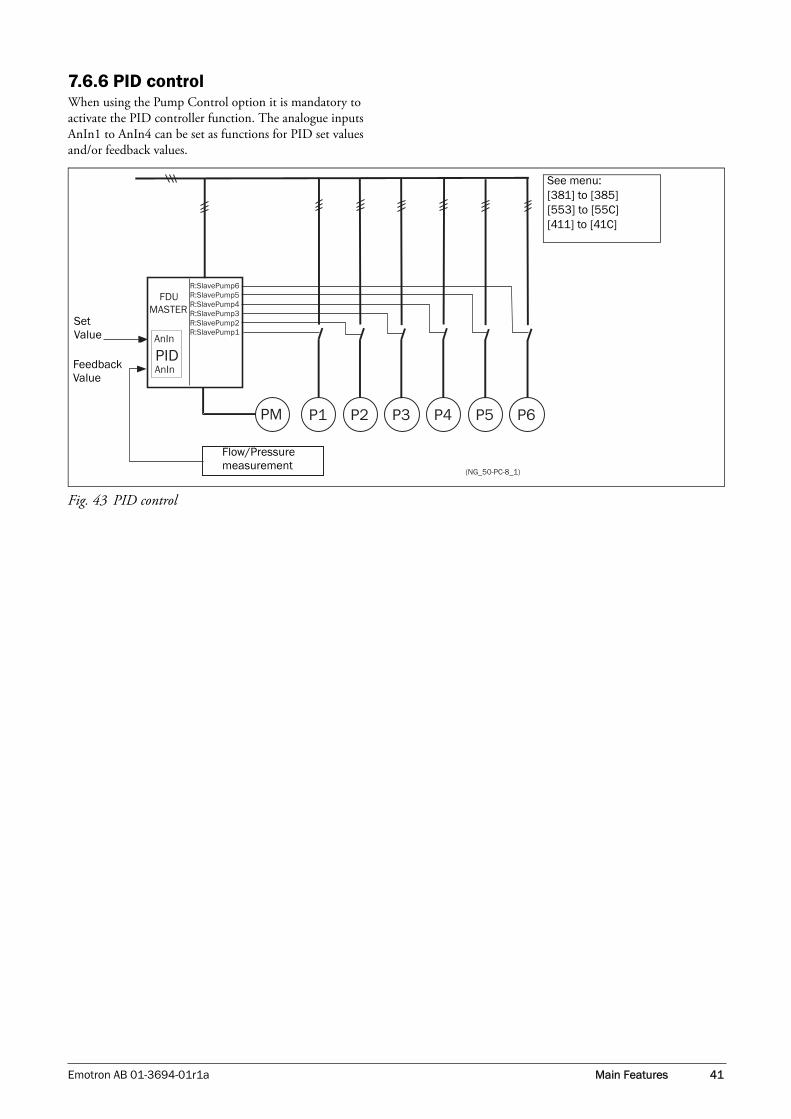
Emotron AB 01-3694-01r1a Main Features 41
7.6.6 PID controlWhen using the Pump Control option it is mandatory to activate the PID controller function. The analogue inputs AnIn1 to AnIn4 can be set as functions for PID set values and/or feedback values.
Fig. 43 PID control
P1 P2 P3 P4 P5 P6PM
FDUMASTER
R:SlavePump6R:SlavePump5R:SlavePump4R:SlavePump3R:SlavePump2R:SlavePump1
AnIn
AnIn
PID
(NG_50-PC-8_1)
See menu:[381] to [385][553] to [55C][411] to [41C]
Set Value
FeedbackValue
Flow/Pressuremeasurement

42 Main Features Emotron AB 01-3694-01r1a
7.6.7 Wiring Alternating MasterFig. 44 and Fig. 45 show the relay functions MasterPump1-6 and SlavePump1-6. The Master and Additional contactors also interlock with each other to prevent dual powering of the pump and damage to the inverter. (K1M/K1S, K2M/K2S, K3M/K3S). Before running, the FDU will select a pump to be Master, depending on the pump run times.
Fig. 44 Power connections for Alternating MASTER circuit with 3 pumps
Fig. 45 Control connections for Alternating MASTER circuit with 3 pumps
CAUTION: The wiring for the Alternating Mastercontrol needs special attention and shouldbe wired exactly as described here, to avoiddestructive short circuiting at the output ofthe inverter.
!
P13~
P23~
P33~
PE L1 L2 L3
U V W
FDU
PEL1L2L3
K1S
K1M K2M
K2S K3S
K3M
(NG_50-PC-10_1)
K1S
B2:R1
SlavePump1
K1M
B1:R1
MasterPump1
~
N
(NG_50-PC-11_3)
K2M
B1:R2
MasterPump2
K2S
B2:R2
SlavePump2
K3M
B1:R3
MasterPump3
K3S
B2:R3
SlavePump3
K1S K1M K2MK2S K3MK3S

Emotron AB 01-3694-01r1a Main Features 43
7.6.8 Checklist And Tips
1. Main Functions
Start by choosing which of the two main functions to use: - "Alternating MASTER" functionIn this case the “Master” pump can be alternated, althoug this function needs slightly more complicated wiring than the “Fixed MASTER” function described below. The I/O Board option is necessary.- "Fixed MASTER" function: One pump is always the master, only the additional pumps alternate. Notice that there is a big difference in the wiring of the system between these main functions, so it not possible to switch between these 2 functions later on. For further information see section 7.6.2, page 39.
2. Number of pumps/drives
If the system consists of 2 or 3 pumps the I/O Board option is not needed. However, this does mean that the following functions are not then possible:- "Alternating MASTER" function- With isolated inputsWith the I/O Board option installed, the maximum number of pumps is:- 6 pumps if "Alternating MASTER" function is selected. (see section 7.6.3 on page 39)- 7 pumps if "Fixed MASTER" function is selected. (see section 7.6.2, page 39)
3. Pump size
- "Alternating MASTER" function:The sizes of the pumps must be equal.- "Fixed MASTER" function: The pumps may have different power sizes, but the master pump (FDU) must always have the greatest power.
4. Programming the Digital inputs
If the digital inputs are used, the digital input function must be set to Drive feedback.
5. Programming the Relay outputs
After the Pump controller is switched on in menu [391] the number of drives (pumps, fans, etc.) must be set in menu [392] (Number of Drives). The relays themselves must be set to the function SlavePump1-6 and if Alternate master is used, MasterPump1-6 as well.
6. Equal Pumps
If all pumps are equal in power size it is likely that the Upper band is much smaller than the Lower band, because the max-imum pump discharge of the master pump is the same if the pump is connected to the mains (50Hz). This can give a very narrow hysteresis causing an unstable control area in the flow/pressure. By setting the maximum frequency of the inverter only slightlyabove 50Hz it means that the master pump has a slightly bigger pump discharge than the pump on the mains. Of course caution is essential in order to prevent the master pump running at a higher frequency for a longer period of time, which in turn prevents the master pump from overloading.
7. Minimum Speed
With pumps and fans it is normal to use a minimum speed, because at lower speed the discharge of the pump or fan will be low until 30-50% of the nominal speed (depending on size, power, pump properties, etc.). When using a minimum speed, a much smoother and better control range of the whole system will be achieved.

44 Main Features Emotron AB 01-3694-01r1a
7.6.9 Functional Examples of Start/Stop Transitions
Starting an additional pumpThis figure shows a possible sequence with all levels and functions involved when a additional pump is started by means of the pump control relays. The starting of the sec-ond pump is controlled by one of the relay outputs. The relay in this example starts the pump directly on line. Of
course other start/stop equipment like a soft starter could be controlled by the relay output.
Fig. 46 Time sequence starting an additional pump
Flow Set view ref. [310]
Feedback Flow
time
Master pump
Max speed
Speed
Transition Speed Start
Min speed Lower band
Upper band
Start delay [399] Settle time start [39D]
Start ramp dependson start method
Start command
Speed
2nd pump
time
time
[39E]
[343]
[341]

Emotron AB 01-3694-01r1a Main Features 45
Stopping an additional pumpThis figure shows a possible sequence with all levels and functions involved when a additional pump is stopped by means of the pump control relays. The stopping of the sec-ond pump is controlled by one of the relay outputs. The relay in this example stops the pump directly on line. Of course other start/stop equipment like a soft starter could be controlled by the relay output.
Fig. 47 Time sequence stopping an additional pump
(NG_50-PC-20_1)
Set view ref. [310]
Feedback Flow
time
Master pump
Max speed
Speed
Transition Speed Stop
Min speedLower band
Upper band
Stop delay [39A] Settle time stop [39F]
Stop ramp dependson start method
Stop command
Speed
2nd pump
time
time
[39G]
[343]
[341]

46 Main Features Emotron AB 01-3694-01r1a

Emotron AB 01-3694-01r1a EMC and Machine Directive 47
8. EMC and Machine Directive
8.1 EMC standardsThe variable speed drive complies with the following stand-ards:
EN61800-3/A11 Adjustable speed electronic power drive systems, part 3, EMC product standards:
Standard: 2nd environment
Optional: 1st environment, restricted distribution
8.2 Stop categories and emergency stop
The following information is important if emergency cir-cuits are used or needed in the installation where a variable speed drive is used. EN 60204-1 defines 3 stop categories:
Category 0: Uncontrolled STOP: Stopping by switching off the supply voltage. A mechanical stop must be activated. This STOP may not be imple-mented with the help of a variable speed drive or its input/output signals.
Category 1: Controlled STOP: Stopping until the motor has come to rest, after which the mains supply is switched off. This STOP may not be imple-mented with the help of a variable speed drive or its input/output signals.
Category 2: Controlled STOP: Stopping while the supply voltage is still present. This STOP can be implemented with each of the variable speed drive´s STOP command.
WARNING: EN 60204-1 specifies that every machine must be provided with a category 0 stop. If the application prevents this from being implemented, this must be explicitly
stated. Furthermore, every machine must be provided with an Emergency Stop function. This emergency stop must ensure that the voltage at the machine contacts, which could be dangerous, is removed as quickly as possible, without resulting in any other danger. In such an Emergency Stop situation, a category 0 or 1 stop may be used. The choice will be decided on the basis of the possible risks to the machine.

48 EMC and Machine Directive Emotron AB 01-3694-01r1a

Emotron AB 01-3694-01r1a Operation via the Control Panel 49
9. Operation via the Control Panel
This chapter describes how to use the control panel. The VSD can be delivered with a control panel or a blank panel.
9.1 GeneralThe control panel displays the status of the VSD and is used to set all the parameters. It is also possible to control the motor directly from the control panel. The control panel can be built-in or locatedexternally via serial communica-tion. The VSD can be ordered without the control panel. Instead of the control panel there will be a blank panel.
9.2 The control panel
Fig. 48 Control panel
9.2.1 The displayThe display is backlit and consists of 2 rows, each with space for 16 characters. The display is divided into six areas.
The different areas in the Preferred Window are described below:
Fig. 49 The display
Area A: Shows the actual menu number (3 or 4 digits).
Area B Shows if the menu is in the toggle loop or theVSD is set for Local operation.
Area C: Shows the heading of the active menu.
Area D: Shows the status of the VSD (3 digits). The following status indications are possible:
Acc : AccelerationDec : DecelerationI2t : Active I2t protectionRun : Motor runsTrp : TrippedStp : Motor is stoppedVL : Operating at Voltage limitSL : Operating at Speed limitCL : Operating at Current limitTL : Operating at Torque limitOT : Operating at Temperature LimitLV : Operating at Low VoltageSby : Operating from Standby power supply
If this position is blinking, it means thatthe VSD Safe stop is activated.
Area E: Shows active parameter set and if it is a motorparameter.
Area F: Shows the setting or selection in the active menu.This area is empty at the 1st level and 2nd levelmenu. This area also shows warnings and alarmmessages.
Fig. 50 Example 1st level menu
Fig. 51 Example 2nd level menu
Fig. 52 Example 3d level menu
Fig. 53 Example 4th level menu
NOTE: The VSD can run without the control panel being connected. However the settings must be such that all control signals are set for external use.
LC Display
LEDs
Control Keys
Toggle Key
Function KeysPREV NEXT ESC
ENTER
RESET
LOC/REM
221 Motor VoltStp M1: 400V
TA
A C
D F
B
E
300 Process ApplStp
220 Motor DataStp
221 Motor VoltStp M1: 400VA
4161 Max AlarmStp 0.1sA

50 Operation via the Control Panel Emotron AB 01-3694-01r1a
9.2.2 Indications on the displayThe display can indicate +++ or - - - if a parameter is out of range. In the VSD there are parameters which are dependent on other parameters. For example, if the speed reference is 500 and the maximum speed value is set to a value below 500, this will be indicated with +++ on the display. If the minimum speed value is set over 500, - - - is displayed.
9.2.3 LED indicatorsThe symbols on the control panel have the following func-tions:
Fig. 54 LED indications
9.2.4 Control keysThe control keys are used to give the Run, Stop or Reset commands directly. As default these keys are disabled, set for remote control. Activate the control keys by selecting Key-board in the menus Ref Control [214] and Reset Ctrl [216].
If the Enable function is programmed on one of the digital inputs, this input must be active to allow Run/Stop com-mands from the control panel.
9.2.5 The Toggle and Loc/Rem KeyThis key has two functions: Toggle and Loc/Rem. As default the function is set to Toggle.
Hold the toggle key pressed for more than five seconds (if [217], is set to ON) to switch the function of the key.
Toggle functionUsing the toggle function makes it possible to easily step through selected menus in a loop. The toggle loop can con-tain a maximum of ten menus. As default the toggle loop contains the menus needed for Quick Setup. You can use the toggle loop to create a quick-menu for the parameters that are most importance to your specific application.
Add a menu to the toggle loop1. Go to the menu you want to add to the loop.
2. Press the Toggle key and keep it pressed while pressing the + key.
Delete a menu from the toggle loop1. Go to the menu you want to delete using the toggle key.
2. Press the Toggle key and keep it pressed while pressing the - key. The message Delete? appears in the menu.
3. Confirm with Enter. The next menu in the loop is shown.
Delete all menus from the toggle loop1. Press the Toggle key and keep it pressed while pressing
the Esc key. The message Delete? is displayed.
2. Confirm with Enter. The menu Preferred view [100] is displayed.
Table 17 LED indication
SymbolFunction
ON BLINKING OFF
POWER (green)
Power on ---------------- Power off
TRIP (red) VSD tripped Warning/Limit No trip
RUN (green)
Motor shaft rotates
Motor shaft acc/dec
Motor stopped
NOTE: If the control panel is built in, the backlight of the display has the same function as the Power LED in Table 17 (Blank panel LEDs).
(NG_06-F61)
RunGreen
TripRed
PowerGreen
Table 18 Control keys
RUN L:gives a start with left rotation
STOP/RESET:stops the motor or resets the VSD after a trip
RUN R:gives a start with right rotation
NOTE: It is not possible to simultaneously activate the Run/Stop commands from the keyboard and remotely from the terminal strip (terminals 1-22).
NOTE: Do not keep the Toggle key pressed for more than five seconds without pressing either the +, - or Esc key, as this may activate the Loc/Rem function of this key instead. See menu [217].
RESET
LOC/REM

Emotron AB 01-3694-01r1a Operation via the Control Panel 51
Default toggle loopThe figure below shows the default toggle loop. This loop contains the necessary menus that need to be set before starting. Press Toggle to enter menu [211] then use the Next key to enter the sub menus [212] to [21A] and enter the parameters. When you press the Toggle key again, menu [221] is displayed.
Fig. 55 Default toggle loop
Indication of menus in toggle loopMenus included in the toggle loop are indicated with a in area B in the display.
Loc/Rem functionThe Loc/Rem function of this key is disabled as default. Enable the function in menu [217].
With the function Loc/Rem you can change between local and remote control of the VSD from the control panel.
Change control mode1. Press the Loc/Rem key for five seconds, until Local? or
Remote? is displayed.
2. Confirm with Enter.
3. Cancel with Esc.
Local modeLocal mode is used for temporary operation. When switched to LOCAL operation, the VSD can only be controlled via the keys on the Control Panel. The actual status of the VSD will not change, e.g. Run/Stop conditions and the actual speed will remain exactly the same. When the VSD is set to
Local operation, the display will show in area B in the display.
The VSD will be started and stopped using the keys on the control panel. The reference signal can be controlled using the + and - keys on the keyboard, when in the menu [310].
Remote modeWhen the VSD is switched to REMOTE operation, the VSD will be controlled according to selected control meth-ods in the menu’s Reference Control [214], Run/Stop Con-trol [215] and Reset Control [216]. The actual operation status of the VSD will reflect the status and settings of the programmed control selections, e.g. Start/Stop status and settings of the programmed control selections, acceleration or deceleration speed according to the selected reference value in the menu Acceleration Time [331] / Deceleration Time [332].
To monitor the actual Local or Remote status of the VSD control, a “Loc/Rem” function is available on the Digital Outputs or Relays. When the VSD is set to Local, the signal on the DigOut or Relay will be active high, in Remote the signal will be inactive low. See menu Digital Outputs [540] and Relays [550].
9.2.6 Function keysThe function keys operate the menus and are also used for programming and read-outs of all the menu settings.
Fig. 56 Menu structure
100211
212
231
232
213
238
LOC/REM
NEXT
NEXT
221
321331
341
381
411
511Toggle loop
Sub menus
Sub menus
T
Table 19 Function keys
ENTER key:
- step to a lower menulevel
- confirm a changed setting
ESCAPE key:
- step to a highermenu level
- ignore a changedsetting, withoutconfirming
PREVIOUS key:
- step to a previousmenu within the samelevel
- go to more significantdigit in edit mode
NEXT key:
- step to a next menuwithin the same level
- go to less significantdigit in edit mode
- key:- decrease a value- change a selection
+ key:- increase a value- change a selection
L
ENTER
ESC
PREVPREV
NEXTNEXT

52 Operation via the Control Panel Emotron AB 01-3694-01r1a
9.3 The menu structureThe menu structure consists of 4 levels:
This structure is consequently independent of the number of menus per level.
For instance, a menu can have only one selectable menu (menu Set/View Reference Value [310]), or it can have 17 selectable menus (menu Speeds [340]).
Fig. 57 Menu structure
9.3.1 The main menuThis section gives you a short description of the functions in the Main Menu.
100 Preferred ViewDisplayed at power-up. It displays the actual frequency and current as default. Programmable for many other read-outs.
200 Main SetupMain settings to get the VSD operable. The motor data set-tings are the most important. Also option utility and set-tings.
300 Process and Application ParametersSettings more relevant to the application such as Reference Speed, torque limitations, PID control settings, etc.
400 Shaft Power Monitor and Process Protection
The monitor function enables the VSD to be used as a load monitor to protect machines and processes against mechani-cal overload and underload.
500 Inputs/Outputs and Virtual Connections
All settings for inputs and outputs are entered here.
600 Logical Functions and TimersAll settings for conditional signal are entered here.
700 View Operation and StatusViewing all the operational data like frequency, load, power, current, etc.
800 View Trip LogViewing the last 10 trips in the trip memory.
900 Service Information and VSD DataElectronic type label for viewing the software version and VSD type.
9.4 Programming during operation
Most of the parameters can be changed during operation without stopping the VSD. Parameters that can not be changed are marked with a lock symbol in the display.
9.5 Editing values in a menuThe values in the second row in a menu can be changed in two different ways.
Alternative 1When you press the + or - keys to change a value, the cursor is blinking to the left in the display and the value is increased or decreased when you press the appropriate key. If you keep the + or - keys pressed, the value will increase or decrease continuously. When you keep the key pressed the change speed will increase. The Toggle key is used to change the sign of the entered value. The sign of the value will also change when zero is passed. Press Enter to confirm the value.
Main Menu1st level
The first character in the menu number.
2nd level The second character in the menu number.
3rd level The third character in the menu number.
4th level The fourth character in the menu number.
NOTE: If there are more than 10 menus within one level, the numbering continues in alphabetic order.
4131
4132
4133
NG_06-F28
NOTE: If you try to change a function during operation that only can be changed when the motor is stopped, the message “Stop First” is displayed.
261 BaudrateStp 38400
331 Acc TimeStp 2.00sA
Blinking

Emotron AB 01-3694-01r1a Operation via the Control Panel 53
Alternative 2Press the + or - key to enter edit mode. Then press the Prev or Next key to move the cursor to the right of the value that should be changed. The cursor will make the selected char-acter blink. Move the cursor using the Prev or Next keys. When you press the + or - keys, the character at the cursor position will increase or decrease. This alternative is suitable when you want to make large changes, i.e. from 2 s to 400 s.
To change the sign of the value, press the toggle key. This make it possible to enter negative values.
Example: When you press Next the 4 will blink.
Press Enter to save the setting and Esc to leave the edit mode.
9.6 Programming exampleThis example shows how to program a change of the Acc. Time set from 2.0 s to 4.0 s.
The blinking cursor indicates that a change has taken place but is not saved yet. If at this moment, the power fails, the change will not be saved.
Use the ESC, Prev, Next or the Toggle keys to proceed and to go to other menus.
Fig. 58 Programming example
331 Acc TimeStp 4.00sA
Blinking
Menu 100 appears after power-up.
Press Next for menu [200].
Press Next for menu [300].
Press Enter for menu [310].
Press Next two times for menu [330].
Press Enter for menu [331].
Keep key pressed until desired value has been reached.
Save the changed value by pressing Enter.
100 0HzStp 0.0A
NEXT
200 MAIN SETUPStp
NEXT
300 PARAM SETSStp
ENTER
310 Set/View Ref Stp
NEXT
330 Run/StopStp
ENTER
331 Acc TimeStp 2.00sA
331 Acc TimeStp 2.00sA
Blinking
ENTER
331 Acc TimeStp 4.00sA

54 Operation via the Control Panel Emotron AB 01-3694-01r1a

Emotron AB 01-3694-01r1a Serial communication 55
10. Serial communication
It is possible to temporarily connect a personal computer with for example the software EmoSoftCom (programming and monitoring software) to the RS232 connector on the control panel. This can be useful when copying parameters between variable speed drives etc. For permanent connection of a personal computer you have to use one of the commu-nication option boards.
Fig. 59 Mounting frame for the control panel
10.1 Description of the EInt formats
Modbus parameters can have different formats e.g. a stand-ard unsigned/signed integer, or eint. EInt, which is described below. All parameters written to a register may be rounded to the number of significant digits used in the internal sys-tem.
ExampleIf you write the value 1004 to a register and this register has 3 significant digits, it will be stored as 1000.
In the Emotron floating point format (F=1), one 16-bit word is used to represent large (or very small numbers) with 3 significant digits.
If data is read or written as a fixed point (i.e. no decimals) number between 0-32767, the Emotron 15-bit fixed point format (F=0) may be used.
F=Format. 1=Emotron floating point format, 0=15 bit Emotron 15-bit fixed point format.
The matrix below describes the contents of the 16-bit word for the two different EInt formats:
Example of Emotron floating point format
A signed number should be represented as a two comple-ment binary number, like below:
Value Binary
The value represented by the EInt floating point format is m·10e.
To convert a value from the EInt floating point format to a floating point value, use the formula above.
To convert a floating point value to the EInt floating point format, see the code float_to_eint below.
ExampleThe number 1.23 would be represented by this in EInt
The value is then 123x10-2 = 1.23
NOTE: This RS232 port is not isolated.
B15 B14 B13 B12 B11 B10 B9 B8 B7 B6 B5 B4 B3 B2 B1 B0 F=1 e3 e2 e1 e0 m10 m9 m8 m7 m6 m5 m4 m3 m2 m1 m0F=0 B14 B13 B12 B11 B10 B9 B8 B7 B6 B5 B4 B3 B2 B1 B0
e3-e0 4-bit signed exponent. -8..+7 (binary 1000 .. 0111)
m10-m0 11-bit signed mantissa. -1024..+1023 (binary 10000000000..01111111111)
-8 1000
-7 1001
..
-2 1110
-1 1111
0 0000
1 0001
2 0010
..
6 0110
7 0111
F EEEE MMMMMMMMMMM
1 1110 00001111011
F=1 -> Eint
E=-2
M=123

56 Serial communication Emotron AB 01-3694-01r1a
Programming example:
typedef struct{
int m:11; // mantissa, -1024..1023int e: 4; // exponent -8..7unsigned int f: 1; // format, 1->special emoint format
} eint16; //--------------------------------------------------------------------------- unsigned short int float_to_eint16(float value){
eint16 etmp;int dec=0;
while (floor(value) != value && dec<16){
dec++; value*=10;} if (value>=0 && value<=32767 && dec==0)
*(short int *)&etmp=(short int)value;else if (value>=-1000 && value<0 && dec==0){
etmp.e=0;etmp.f=1;etmp.m=(short int)value;
}else{
etmp.m=0;etmp.f=1;etmp.e=-dec;if (value>=0)
etmp.m=1; // Set signelse
etmp.m=-1; // Set signvalue=fabs(value);while (value>1000){
etmp.e++; // increase exponentvalue=value/10;
}value+=0.5; // roundetmp.m=etmp.m*value; // make signed
} Rreturn (*(unsigned short int *)&etmp);}//--------------------------------------------------------------------------- float eint16_to_float(unsigned short int value){
float f;eint16 evalue;
evalue=*(eint16 *)&value; if (evalue.f){
if (evalue.e>=0)f=(int)evalue.m*pow10(evalue.e);
elsef=(int)evalue.m/pow10(abs(evalue.e));
}else
f=value;
return f;}//---------------------------------------------------------------------------

Emotron AB 01-3694-01r1a Serial communication 57
Example Emotron 15-bit fixed point formatThe value 72.0 can be represented as the fixed point number 72. It is within the range 0-32767, which means that the 15-bit fixed point format may be used.
The value will then be represented as:
Where bit 15 indicates that we are using the fixed point for-mat (F=0).
B15 B14 B13 B12 B11 B10 B9 B8 B7 B6 B5 B4 B3 B2 B1 B00 0 0 0 0 0 0 0 0 1 0 0 1 0 0 0

58 Serial communication Emotron AB 01-3694-01r1a

Emotron AB 01-3694-01r1a Functional Description 59
11. Functional Description
This chapter describes the menus and parameters in the soft-ware. You will find a short description of each function and information about default values, ranges, etc. There are also tables containing communication information. You will find the Modbus, DeviceNet and Fieldbus address for each parameter as well as the enumeration for the data.
11.1 Resolution of settingsThe resolution for all range settings described in this chapter is 3 significant digits. Exceptions are frequency values which are presented with 4 significant digits. Table 20 shows the resolutions for 3 significant digits.
11.2 Preferred View [100]This menu is displayed at every power-up. During opera-tion, the menu [100] will automatically be displayed when the keyboard is not operated for 5 minutes. As default it dis-plays the actual current.
Menu [100], Preferred View displays the settings made in menu [110], 1st line, and [120], 2nd line. See Fig. 60.
Fig. 60 Display functions
11.2.1 1st Line [110]Sets the content of the upper row in the menu [100] Pre-ferred View.
Communication information
11.2.2 2nd Line [120]Sets the content of the lower row in the menu [100] Pre-ferred View. Same selection as in menu [110].
NOTE: Functions marked with the sign cannot be changed during Run Mode.
Table 20
3 Digit Resolution
0.01-9.99 0.01
10.0-99.9 0.1
100-999 1
1000-9990 10
10000-99900 100
�
100 0rpmStp 0.0A
100 (1st Line)Stp (2nd Line)
Default: Process Val
Dependent on menu
Process Val 0 Process value selected
Speed 1 Speed selected
Torque 2 Torque selected
Process Ref 3 Process reference selected
Shaft Power 4 Shaft power selected
El Power 5 Electrical power selected
Current 6 Current selected
Output Volt 7 Output voltage selected
Frequency 8 Frequency selected
DC Voltage 9 DC voltage selected
Heatsink Tmp 10 Heatsink temperature selected
Motor Temp 11 Motor temperature selected
VSD Status 12 VSD status selected
Run Time 13 Run Time selected
Energy 14 Energy selected
Mains Time 15 Mains time selected
Modbus Instance no/DeviceNet no: 43001
Profibus slot/index 168/160
Fieldbus format UInt
Modbus format UInt
Default: Current
110 1st Line Stp Process Val
120 2nd Line Stp Current

60 Functional Description Emotron AB 01-3694-01r1a
11.3 Main Setup [200]The Main Setup menu contains the most important settings to get the VSD operational and set up for the application. It includes different sub menus concerning the control of the unit, motor data and protection, utilities and automatic resetting of faults. This menu will instantaneously be adapted to build in options and show the required settings.
11.3.1 Operation [210]Selections concerning the used motor, VSD mode, control signals and serial communication are described in this sub-menu and is used to set the VSD up for the application.
Language [211]Select the language used on the LC Display. Once the lan-guage is set, this selection will not be affected by the Load Default command.
Communication information
Select Motor [212]This menu is used if you have more than one motor in your application. Select the motor to define. It is possible to define up to four different motors, M1 to M4, in the VSD.
Communication information
Drive Mode [213]The function Drive Mode is set to obtain the best setup for the application. This selection also sets all the reference sig-nals and read-outs depending on the selected mode.
• V/Hz Mode, output frequency in rpm, is used when sev-eral motors in parallel are connected.
Communication information
Default: English
English 0 English selected
Svenska 1 Swedish selected
Nederlands 2 Dutch selected
Deutsch 3 German selected
Français 4 French selected
Español 5 Spanish selected
Russian 6 Russian selected
Modbus Instance no/DeviceNet no: 43011
Profibus slot/index 168/170
Fieldbus format UInt
Modbus format UInt
211 LanguageStp EnglishA
Default: M1
M1 0
Motor Data is connected to selected motor.
M2 1
M3 2
M4 3
Modbus Instance no/DeviceNet no: 43012
Profibus slot/index 168/171
Fieldbus format UInt
Modbus format UInt
Default: V/Hz
V/Hz 2
All control loops are related to frequency control. In this mode multi-motor applica-tions are possible.
NOTE: All the functions and menu read-outs with regard to speed and rpm (e.g. Max Speed = 1500 rpm, Min Speed=0 rpm, etc.) remain speed and rpm, although they represent the output frequency.
Modbus Instance no/DeviceNet no: 43013
Profibus slot/index 168/172
Fieldbus format UInt
Modbus format UInt
212 Select MotorStp M1A
213 Drive ModeStp V/HzA

Emotron AB 01-3694-01r1a Functional Description 61
Reference control [214]To control the speed of the motor, the VSD needs a refer-ence signal. This reference signal can be controlled by a remote source from the installation, the keyboard of the VSD, or by serial or fieldbus communication. Select the required reference control for the application in this menu.
Communication information
Run/Stop Control [215]This function is used to select the source for run and stop commands. Start/stop via analogue signals can be achieved by combining a few functions. This is described in the Chapter 7. page 31.
Communication information
Reset Control [216]When the VSD is stopped due to a failure, a reset command is required to make it possible to restart the VSD. Use this function to select the source of the reset signal.
Communication information
Local/Remote key function [217]The Toggle key on the keyboard, see section 9.2.5, page 50, has two functions and is activated in this menu. As default the key is set to operate as a Toggle key that moves you easily through the menus in the toggle loop. The second function of the key allows you to easily swap between Local and Remote operation of the VSD.
Default: Remote
Remote 0The reference signal comes from the ana-logue inputs of the terminal strip (termi-nals 1-22).
Keyboard 1
Reference is set with the + and - keys on the Control Panel. Can only be done in menu Your Process [310]. Now the + and - keys will set the reference value.
Com 2The reference is set via the serial commu-nication (RS 485, Fieldbus.)
Option 3The reference is set via an option. Only available if the option can control the ref-erence value.
NOTE: If the reference is switched from Remote to Control Panel, the last remote reference value will be the default value for the control panel.
Modbus Instance no/DeviceNet no: 43014
Profibus slot/index 168/173
Fieldbus format UInt
Modbus format UInt
Default: Remote
Selections Same as menu [214]
Modbus Instance no/DeviceNet no: 43015
Profibus slot/index 168/174
Fieldbus format UInt
Modbus format UInt
214 Ref ControlStp RemoteA
215 Run/Stp CtrlStp RemoteA
Default: Remote
Remote 0The command comes from the inputs of the terminal strip (terminals 1-22).
Keyboard 1The command comes from the command keys of the Control Panel.
Com 2The command comes from the serial communication (RS 485, Fieldbus).
Remote + Keyb
3The command comes from the inputs of the terminal strip (terminals 1-22) or the keyboard.
Com + Keyb
4The command comes from the serial communication (RS485, Fieldbus) or the keyboard.
Rem+Keyb+Com
5
The command comes from the inputs of the terminal strip (terminals 1-22), the keyboard or the serial communication (RS485, Fieldbus).
Option 6The command comes from an option. Only available if the option can control the reset command.
Modbus Instance no/DeviceNet no: 43016
Profibus slot/index 168/175
Fieldbus format UInt
Modbus format UInt
Default: Off
On 0 Local/Rem enabled
Off 1 Local/Rem off
216 Reset CtrlStp RemoteA
217 Local/RemStp OffA

62 Functional Description Emotron AB 01-3694-01r1a
Communication information
Lock Code [218]To prevent the keyboard being used or to change the setup of the VSD and/or process control, the keyboard can be locked with a password. This menu, Lock Code [218], is used to lock and unlock the keyboard. Enter the password “291” to lock/unlock the keyboard operation. If the key-board is not locked (default) the selection “Lock Code?” will appear. If the keyboard is already locked, the selection “Unlock Code?” will appear.
When the keyboard is locked, parameters can be viewed but not changed. The reference value can be changed and the VSD can be started, stopped and reversed if these functions are set to be controlled from the keyboard.
Rotation [219]
Overall limitation of motor rotation directionThis function limits the overall rotation, either to left or right or both directions. This limit is prior to all other selec-tions, e.g.: if the rotation is limited to right, a Run-Left com-mand will be ignored. To define left and right rotation we assume that the motor is connected U-U, V-V and W-W.
Speed Direction and RotationThe speed direction can be controlled by:
• RunR/RunL commands on the control panel.
• RunR/RunL commands on the terminal strip (terminals 1-22).
• Via the serial interface options.
• The parameter sets.
Fig. 61
In this menu you set the general rotation for the motor.
Communication information
Modbus Instance no/DeviceNet no: 43017
Profibus slot/index 168/176
Fieldbus format UInt
Modbus format UInt
Default: 0
Range: 0–9999
218 Lock CodeStp 0 A
Default: R + L
R 1Speed direction is limited to right rota-tion. The input and key RunL are disa-bled.
L 2Speed direction is limited to left rotation. The input and key RunR are disabled.
R+L 3 Both speed directions allowed.
Modbus Instance no/DeviceNet no: 43019
Profibus slot/index 168/178
Fieldbus format UInt
Modbus format UInt
Right
Left
219 RotationStp R+LA

Emotron AB 01-3694-01r1a Functional Description 63
11.3.2 Start Signal Level/Edge [21A]In this menu you select the way to control the inputs for RunR, RunL, Stop and Reset that are operated via the dig-ital inputs on the terminal strip. The inputs are default set for level-control, and will be active as long as the input is made and kept high. When edge-control is selected, the input will be activated by the low to high transition of the input.
Communication information
CAUTION: Level controlled inputs DO NOT comply with the Machine Directive if the inputs are directly used to start and stop the machine.
11.3.3 Motor Data [220]In this menu you enter the motor data to adapt the VSD to the connected motor. This will increase the control accuracy as well as different read-outs and analogue output signals.
Motor M1 is selected as default and motor data entered will be valid for motor M1. If you have more than one motor you need to select the correct motor in menu [212] before entering motor data.
Motor voltage [221]Set the nominal motor voltage.
Communication information
Motor frequency [222]Set the nominal motor frequency.
Communication information
Default: Level
Level 0
The inputs are activated or deactivated by a continuous high or low signal. Is commonly used if, for example, a PLC is used to operate the VSD.
Edge 1The inputs are activated by a “low” to “high” transition.
Modbus Instance no/DeviceNet no: 43020
Profibus slot/index 168/179
Fieldbus format UInt
Modbus format UInt
NOTE: Edge controlled inputs comply with the Machine Directive (see the Chapter 8. page 47) if the inputs are directly used to start and stop the machine.
NOTE: All parameters for motor data cannot be changed during run mode.
NOTE: The default settings are for a standard 4-pole motor according to the nominal power of the VSD.
21A Level/EdgeStp LevelA
!
Default:400 V for FDU48500 V for FDU50690 V for FDU69
Range: 100-700 V
Resolution 1 V
Modbus Instance no/DeviceNet no: 43041
Profibus slot/index 168/200
Fieldbus formatLong,1=0.1 V
Modbus format EInt
Default: 50 Hz
Range: 24-300 Hz
Resolution 1 Hz
Modbus Instance no/DeviceNet no: 43042
Profibus slot/index 168/201
Fieldbus formatLong,1=1 Hz
Modbus format EInt
�221 Motor VoltsStp M1: 400VA
�222 Motor FreqStp M1: 50HzA

64 Functional Description Emotron AB 01-3694-01r1a
Motor power [223]Set the nominal motor power.
Communication information
PNOM is the nominal VSD power.
Motor current [224]Set the nominal motor current.
Communication information
INOM is the nominal VSD current.
Motor Speed [225]Set the nominal asynchronous motor speed.
Communication information
Motor Poles [226]When the nominal speed of the motor is ≤500 rpm, the additional menu for entering the number of poles, [226], appears automatically. In this menu the actual pole number can be set which will increase the control accuracy of the VSD.
Communication information
Motor Cos ϕ [227]Set the nominal Motor cosphi (power factor).
Default: PNOMVSD
Range: 1W-120% x PNOM
Resolution 3 significant digits
Modbus Instance no/DeviceNet no: 43043
Profibus slot/index 168/202
Fieldbus formatLong,1=1 W
Modbus format EInt
Default: INOM
Range: 25 - 150% x INOM
Modbus Instance no/DeviceNet no: 43044
Profibus slot/index 168/203
Fieldbus formatLong,1=0.1 A
Modbus format EInt
WARNING: Do not connect motors with less than 25% of the nominal power of the VSD. This may disrupt the control of the motor.
�223 Motor PowerStp M1: (PNOM)kWA
�224 Motor CurrStp M1: (INOM)AA
Default: nMOT (see note section 11.3.3, page 63)
Range: 400 - 18000 rpm
Resolution 1 rpm, 4 sign digits
Modbus Instance no/DeviceNet no: 43045
Profibus slot/index 168/204
Fieldbus formatUInt1=1 rpm
Modbus format UInt
Default: no default value
Range: 2-144
Modbus Instance no/DeviceNet no: 43046
Profibus slot/index 168/205
Fieldbus formatLong,1=1 pole
Modbus format EInt
Default: Depends on PNOM
Range: 0.50 - 1.00
�225 Motor SpeedStp M1: (nMOT)rpmA
�226 Motor PolesStp M1:A
�227 Motor CosϕStp M1:A

Emotron AB 01-3694-01r1a Functional Description 65
Communication information
Motor ventilation [228]Parameter for setting the type of motor ventilation. Affects the characteristics of the I2t motor protection by lowering the actual overload current at lower speeds.
Communication information
When the motor has no cooling fan, None is selected and the start current level is limited to 55% of rated motor cur-rent.
With a motor with a shaft mounted fan, Self is selected and the start current for overload is limited to 87% from 20% of synchronous speed. At lower speed, the overload current allowed will be smaller.
When the motor has an external cooling fan, Forced is selected and the overload start current allowed starts at 90% from rated motor current at zero speed, up to nominal motor current at 70% of synchronous speed.
Fig. 62 shows the characteristics with respect for Nominal Current and Speed in relation to the motor ventilation type selected.
Fig. 62 I2t curves
Motor Identification Run [229]This function is used when the VSD is put into operation for the first time. To achieve an optimal control perform-ance, fine tuning of the motor parameters using a motor ID run is needed. During the test run the display shows “Test Run” blinking.
To activate the Motor ID run, select “Short”, make the Ena-ble input HIGH and press RunL or RunR on the control panel. If menu [214] Rotation is set to L or R, the Motor ID run follows this. The ID run can be aborted by giving a Stop command via the control panel or Enable input. The param-eter will automatically return to OFF when the test is com-pleted. The message “Test Run OK!” is displayed. Before the VSD can be operated normally again, the Enable input must be low or press the STOP/RESET key on the control panel.
During the Short ID run the motor does not rotate, but it is switched on. The VSD measures the rotor and stator resist-ance.
.
Communication information
Modbus Instance no/DeviceNet no: 43047
Profibus slot/index 168/206
Fieldbus formatLong,1=0.01
Modbus format EInt
Default: Self
None 0 Limited I2t overload curve.
Self 1Normal I2t overload curve. Means that the motor stands lower current at low speed.
Forced 2Expanded I2t overload curve. Means that the motor stands almost the whole cur-rent also at lower speed.
Modbus Instance no/DeviceNet no: 43048
Profibus slot/index 168/207
Fieldbus format UInt
Modbus format UInt
�228 Motor VentStp M1: SelfA
Default: Off, see Note
Off 0 Not active
Short 1Parameters are measured with injected DC current. No rotation of the shaft will occur.
Modbus Instance no/DeviceNet no: 43049
Profibus slot/index 168/208
Fieldbus format UInt
Modbus format UInt
1.000.900.87
0.55
0.20 0.70 2.00xSync Speed
xInom for I2t
Forced
Self
None
�229 Motor ID-RunStp M1: OffA

66 Functional Description Emotron AB 01-3694-01r1a
Motor Sound [22A]Sets the sound characteristic of the VSD output stage by changing the switching frequency and/or pattern. Generally the motor noise will go down at higher switching frequen-cies.
Communication information
Encoder Feedback [22B]This parameter enables or disables the encoder feedback from the motor to the VSD.
Communication information
Encoder Pulses [22C]This parameter describes the number of pulses per rotation for your encoder, i.e. it is encoder specific. For more infor-mation please see the encoder manual.
Communication information
Encoder Speed [22D]This parameter shows the measured motor speed. To check if the encoder is correctly installed, set Encoder [23B] to Off, run the VSD at any speed and compare with the value in this menu. The value in this menu [22D] should be about the same as the motor speed [712]. If you get the wrong sign for the value, swap encoder input A and B.
Communication information
NOTE: To run the VSD it is not mandatory for the ID RUN to be executed, but without it the performance will not be optimal.
NOTE: If the ID Run is aborted or not completed the message “Interrupted!” will be displayed. To restart the Enable input must be low again. The previous data do not need to be changed in this case. Check that the motor data are correct.
Default: F
E 0 Switching frequency 1.5 kHz
F 1 Switching frequency 3 kHz
G 2 Switching frequency 6 kHz
H 3Switching frequency 6 kHz, random fre-quency (+750 Hz)
Modbus Instance no/DeviceNet no: 43050
Profibus slot/index 168/209
Fieldbus format UInt
Modbus format UInt
NOTE: At switching frequencies >3 kHz derating may become necessary. If the heat sink temperature gets too high the switching frequency is decreased to avoid tripping. This is done automatically in the VSD. The default switching frequency is 3 kHz.
Default: Off
On 0 Encoder feedback enabled
Off 1 Encoder feedback disabled
�22A Motor SoundStp M1: FA
�22B Encoder Stp M1: OffA
Modbus Instance no/DeviceNet no: 43051
Profibus slot/index 168/210
Fieldbus format UInt
Modbus format UInt
Default: 1024
Range: 5–16384
Modbus Instance no/DeviceNet no: 43052
Profibus slot/index 168/211
Fieldbus formatLong1=1 pulse
Modbus format EInt
Unit: rpm
Resolution: speed measured via the encoder
Modbus Instance no/DeviceNet no: 42911
Profibus slot/index 168/70
Fieldbus format Int
Modbus format Int
�22C Enc PulsesStp M1: 1024A
�22D Enc SpeedStp M1: XXrpmA

Emotron AB 01-3694-01r1a Functional Description 67
11.3.4 Motor Protection [230]This function protects the motor against overload based on the standard IEC 60947-4-2.
Motor I2t Type [231]Select the type of I2t protection function.
Communication information
Motor I2t Current [232]Sets the current limit for the motor I2t protection.
Communication information
Motor I2t Time [233]Sets the time of the I2t function. After this time the limit for the I2t is reached if operating with 120% of the I2t current value.
Communication informationDefault: Trip
Off 0 I2t motor protection is not active.
Trip 1When the I2t time is exceeded, the VSD will trip on “Motor I2t”.
Limit 2Before the I2t time is exceeded, the VSD reduces the maximum torque and current to the level set in menu [232].
Modbus Instance no/DeviceNet no: 43061
Profibus slot/index 168/220
Fieldbus format UInt
Modbus format UInt
Default: IMOT for the motor
Range:0–150% Motor INOM of the VSD (depending on the VSD size)
Modbus Instance no/DeviceNet no: 43062
Profibus slot/index 168/221
Fieldbus formatLong1=0.1 A
Modbus format EInt
NOTE: When the selection Limit is set in menu [231], the value must be above the no-load current of the motor.
231 Mot I2t TypeStp M1: TripA
232 Mot I2t CurrStp (IMOT)AA
Default: 60 s
Range: 60–1200 s
Modbus Instance no/DeviceNet no: 43063
Profibus slot/index 168/222
Fieldbus formatLong1=1 s
Modbus format EInt
233 Mot I2t TimeStp M1: 60sA

68 Functional Description Emotron AB 01-3694-01r1a
Fig. 63 I2t function
Fig. 63 shows how the function integrates the square of the motor current according to the Mot I2t Curr [232] and the Mot I2t Time [233].
When the selection Trip is set in menu [231] the VSD trips if this limit is exceeded.
When the selection Limit is set in menu [231] the VSD reduces the torque if the integrated value is 95% or closer to the limit, so that the limit cannot be exceeded.
ExampleIn Fig. 63 the thick grey line shows the following example.
• Menu [232] Mot I2t Curr is set to 10 A.1.2 x 10 A = 12 A
• Menu [233] Mot I2t Time is set to 1000 s.
Thermal Protection [234]Set the PTC input for thermal protection of the motor. The motor thermistors (PTC) must comply with DIN 44081/44082. Please refer to the manual for the PTX-Enc option board.
Menu [234] PTC contain functions to enable or disable the PTC input.
Communication information
10
100
1000
10000
100000
1 1.1 1.2 1.3 1.4 1.5 1.6 1.7 1.8 1.9 2
t [s]
i / I2t-current
60 s (120%)
120 s (120%)
240 s (120%)
480 s (120%)
1000 s (120%)
IMOT / I2t-current
NOTE: If it is not possible to reduce the current, the VSD will trip after exceeding 110% of the limit.
Default: Off
Off 0PTC and PT100 motor protection are disa-bled.
PTC 1Enables the PTC protection of the motor via the insulated option board.
PT100 2Enables the PT100 protection for the motor via the insulated option board.
PTC+PT100 3Enables the PTC protection as well as the PT100 protection for the motor via the insulated option board.
Modbus Instance no/DeviceNet no: 43064
Profibus slot/index 168/223
Fieldbus format UInt
Modbus format UInt
NOTE! PTC option and Pt100 selections can only be selected when the option board is mounted.
234 Thermal ProtStp OffA

Emotron AB 01-3694-01r1a Functional Description 69
Motor Class [235]Set the class of motor used. The trip levels for the PT100 sensor will automatically be set according to the setting in this menu.
Communication information
11.3.5 Parameter Set Handling [240]There are four different parameter sets available in the VSD. These parameter sets can be used to set the VSD up for dif-ferent processes or applications such as different motors used and connected, activated PID controller, different ramp time settings, etc.
A parameter set consists of all parameters with the exception of the menu [220] Motor Data, Timer1 [640] and Timer2 [650].
Communication information
The different parameter sets in the VSD have the following DeviceNet instance numbers and Profibus slot/index num-bers:
Parameter set A contains parameters 43001 to 43529. The parameter sets B, C and D contains the same type of infor-mation. For example parameter 43123 in parameter set A contain the same type of information as 44123 in parameter set B.
A DeviceNet instance number can easily be converted into a Profibus slot/index number according to description in sec-tion section 11.9.1, page 136.
Select Set [241]Here you select the parameter set. Every menu included in the parameter sets is designated A, B, C or D depending on the active parameter set. Parameter sets can be selected from the keyboard, via the programmable digital inputs or via serial communication. Parameter sets can be changed during the run.
Communication information
The active set can be viewed with function [721] FI status.
Default: F 140°C
A 100°C 0
E 115°C 1
B 120°C 2
F 140°C 3
F Nema 145°C
4
H 165°C 5
Modbus Instance no/DeviceNet no: 43065
Profibus slot/index 168/224
Fieldbus format UInt
Modbus format UInt
NOTE: This menu is only valid for PT 100.
Parameter set
DeviceNet Instance number
ProfibusSlot/Index
A 43001–43529 168/16 to 170/178
B 44001–44529 172/140 to 174/158
C 45001–45529 176/120 to 178/138
D 46001–46529 180/100 to 182/118
235 Mot ClassStp F 140°CA
Default: A
Selection: A, B, C, D, DigIn, Com, Option
A 0
Fixed selection of one of the 4 parameter sets A, B, C or D.
B 1
C 2
D 3
DigIn 4Parameter set is selected via a digital input. Define which digital input in menu [520], Digital inputs.
Com 5Parameter set is selected via serial com-munication.
Option 6The parameter set is set via an option. Only available if the option can control the selection.
Modbus Instance no/DeviceNet no: 43022
Profibus slot/index 168/181
Fieldbus format UInt
Modbus format UInt
NOTE: The parameters in menu [230], Motor data, are not affected by loading defaults.
241 Select SetStp AA

70 Functional Description Emotron AB 01-3694-01r1a
Copy Set [242]This function copies the content of a parameter set into another parameter set.
Communication information
A>B means that the content of parameter set A is copied into parameter set B.
Load Default Values Into Set [243]With this function three different levels (factory settings) can be selected. When loading the default settings, all changes made in the software are set to factory settings.
Communication information
Copy All Settings to Control Panel [244]All the settings can be copied into the control panel includ-ing the motor data.
Communication information
Load Settings from Control Panel [245]This function will load all four parameter sets from the con-trol panel to the VSD. Parameter sets from the source VSD are copied to all parameter sets in the target VSD, i.e. A to A, B to B, C to C and D to D.
Default: A>B
A>B 0 Copy set A to set B
A>C 1 Copy set A to set C
A>D 2 Copy set A to set D
B>A 3 Copy set B to set A
B>C 4 Copy set B to set C
B>D 5 Copy set B to set D
C>A 6 Copy set C to set A
C>B 7 Copy set C to set B
C>D 8 Copy set C to set D
D>A 9 Copy set D to set A
D>B 10 Copy set D to set B
D>C 11 Copy set D to set C
Modbus Instance no/DeviceNet no: 43021
Profibus slot/index 168/180
Fieldbus format UInt
Modbus format UInt
Default: A
A 0
Only the selected parameter set will revert to its default settings.
B 1
C 2
D 3
ABCD 4All four parameter sets will revert to the default settings.
Factory 5All settings, except 211, 261, 3A1 and 923, will revert to the default settings.
242 Copy SetStp A>BA
243 Default>SetStp AA
Modbus Instance no/DeviceNet no: 43023
Profibus slot/index 168/182
Fieldbus format UInt
Modbus format UInt
NOTE: Trip log hour counter and other VIEW ONLY menus are not regarded as settings and will be unaffected.
NOTE: If “Factory” is selected, the message “Sure?” is displayed. Press the + key to display “Yes” and then Enter to confirm.
Default: No Copy
No Copy 0 Nothing will be copied
Copy 1 Copy all settings
Modbus Instance no/DeviceNet no: 43024
Profibus slot/index 168/183
Fieldbus format UInt
Modbus format UInt
Default: No Copy
No Copy 0 Nothing will be loaded.
A 1 Data from parameter set A is loaded.
B 2 Data from parameter set B is loaded.
C 3 Data from parameter set C is loaded.
D 4 Data from parameter set D is loaded.
ABCD 5Data from parameter sets A, B, C and D are loaded.
244 Copy to CPStp No CopyA
245 Load from CPStp No CopyA
�

Emotron AB 01-3694-01r1a Functional Description 71
Communication information
11.3.6 Trip Autoreset/Trip Conditions [250]
The benefit of this feature is that occasional trips that do not affect the process will be automatically reset. Only when the failure keeps on coming back, recurring at defined times and therefore cannot be solved by the VSD, will the unit give an alarm to inform the operator that attention is required.
Example:In an application it is known that the main supply voltage sometimes disappears for a very short time, a so-called “dip”. That will cause the VSD to trip an “Undervoltage alarm”. Using the Autoreset function, this trip will be acknowledged automatically.
• Enable the Autoreset function by making the reset input continuously high.
• Activate the Autoreset function in the menu [251], Number of trips.
• Select in menus [252] to [25N] the relevant Trip condi-tion that are allowed to be automatically reset by the Autoreset function after the set delay time has expired.
• When a trip cause, e.g. too high motor temperature, allows the VSD to control down to zero speed according to the deceleration ramp, this can be selected as a trip type when each trip occurs.
Number of Trips [251]Any number set above 0 activates the Autoreset. This means that after a trip, the VSD will restart automatically according to the number of attempts selected. No restart attempts will take place unless all conditions are normal.
If the Autoreset counter (not visible) contains more trips than the selected number of attempts, the Autoreset cycle will be interrupted. No Autoreset will then take place.
If there are no trips for more than 10 minutes, the Autoreset counter goes back one place.
If the maximum number of trips has been reached, the trip message hour counter is marked with an “A”.
If the Autoreset is full then the VSD must be reset by a nor-mal Reset.
Example:• Autoreset = 5
• Within 10 minutes 6 trips occur
• At the 6th trip there is no Autoreset, because the Autore-set trip log contains 5 trips already.
• To reset, apply a normal reset: set the reset input high to low and high again to maintain the Autoreset function. The counter is reset.
Communication information
A+Mot 6Parameter set A and Motor data are loaded.
B+Mot 7Parameter set B and Motor data are loaded.
C+Mot 8Parameter set C and Motor data are loaded.
D+Mot 9Parameter set D and Motor data are loaded.
ABCD+Mot 10Parameter sets A, B, C, D and Motor data are loaded.
M1 11 Data from motor 1 is loaded.
M2 12 Data from motor 2 is loaded.
M3 13 Data from motor 3 is loaded.
M4 14 Data from motor 4 is loaded.
M1M2M3M4
15 Data from motor 1, 2, 3 and 4 are loaded.
All 16 All data is loaded from the control panel.
Modbus Instance no/DeviceNet no: 43025
Profibus slot/index 168/184
Fieldbus format UInt
Modbus format UInt
Default: 0 (no Autoreset)
Range: 0–10 attempts
Modbus Instance no/DeviceNet no: 43071
Profibus slot/index 168/230
Fieldbus format UInt
Modbus format UInt
NOTE: An auto reset is delayed by the remaining ramp time.
251 No of TripsStp 0A

72 Functional Description Emotron AB 01-3694-01r1a
Overtemperature [252]Delay time starts counting when the fault is gone. When the time delay has elapsed, the alarm will be reset if the function is active.
Communication information
Overvolt D [253]Delay time starts counting when the fault is gone. When the time delay has elapsed, the alarm will be reset if the function is active
Communication information
Overvolt G [254]Delay time starts counting when the fault is gone When the time delay has elapsed, the alarm will be reset if the function is active.
Communication information
Overvolt [255]Delay time starts counting when the fault is gone. When the time delay has elapsed, the alarm will be reset if the function is active.
Communication information
Default: Off
Off 0 Off
1–3600 1–3600 1–3600 s
Modbus Instance no/DeviceNet no: 43072
Profibus slot/index 168/231
Fieldbus format Long, 1=1 s
Modbus format EInt
NOTE: An auto reset is delayed by the remaining ramp time.
Default: Off
Off 0 Off
1–3600 1–3600 1–3600 s
Modbus Instance no/DeviceNet no: 43075
Profibus slot/index 168/234
Fieldbus format Long, 1=1 s
Modbus format EInt
NOTE: An auto reset is delayed by the remaining ramp time.
252 OvertempStp OffA
253 Overvolt DStp OffA
Default: Off
Off 0 Off
1–3600 1–3600 1–3600 s
Modbus Instance no/DeviceNet no: 43076
Profibus slot/index 168/235
Fieldbus format Long, 1=1 s
Modbus format EInt
Default: Off
Off 0 Off
1–3600 1–3600 1–3600 s
Modbus Instance no/DeviceNet no: 43077
Profibus slot/index 168/236
Fieldbus format Long, 1=1 s
Modbus format EInt
254 Overvolt GStp OffA
255 OvervoltStp OffA

Emotron AB 01-3694-01r1a Functional Description 73
Motor Lost [256]Delay time starts counting when the fault is gone. When the time delay has elapsed, the alarm will be reset if the function is active.
Communication information
Locked Rotor [257]Delay time starts counting when the fault is gone. When the time delay has elapsed, the alarm will be reset if the function is active.
Communication information
Power Fault [258]Delay time starts counting when the fault is gone. When the time delay has elapsed, the alarm will be reset if the function is active.
Communication information
Undervoltage [259]Delay time starts counting when the fault is gone. When the time delay has elapsed, the alarm will be reset if the function is active.
Communication information
Default: Off
Off 0 Off
1–3600 1–3600 1–3600 s
NOTE: Only visible when Motor Lost is selected.
Modbus Instance no/DeviceNet no: 43083
Profibus slot/index 168/242
Fieldbus format Long, 1=1 s
Modbus format EInt
Default: Off
Off 0 Off
1–3600 1–3600 1–3600 s
Modbus Instance no/DeviceNet no: 43086
Profibus slot/index 168/245
Fieldbus format Long, 1=1 s
Modbus format EInt
256 Motor LostStp OffA
257 Locked RotorStp OffA
Default: Off
Off 0 Off
1–3600 1–3600 1–3600 s
Modbus Instance no/DeviceNet no: 43087
Profibus slot/index 168/246
Fieldbus format Long, 1=1 s
Modbus format EInt
Default: Off
Off 0 Off
1–3600 1–3600 1–3600 s
Modbus Instance no/DeviceNet no: 43088
Profibus slot/index 168/247
Fieldbus format Long, 1=1 s
Modbus format EInt
258 Power FaultStp OffA
259 UndervoltageStp OffA

74 Functional Description Emotron AB 01-3694-01r1a
Motor I2t [25A]Delay time starts counting when the fault is gone. When the time delay has elapsed, the alarm will be reset if the function is active.
Communication information
Motor I2t Trip Type [25B]Select the preferred way to react to a Motor I2t trip.
Communication information
PT100 [25C]Delay time starts counting when the fault is gone. When the time delay has elapsed, the alarm will be reset if the function is active.
Communication information
PT100 Trip Type [25D]Delay time starts counting when the fault is gone. When the time delay has elapsed, the alarm will be reset if the function is active.
Communication information
PTC [25E]Delay time starts counting when the fault is gone. When the time delay has elapsed, the alarm will be reset if the function is active.
Communication information
Default: Off
Off 0 Off
1–3600 1–3600 1–3600 s
Modbus Instance no/DeviceNet no: 43073
Profibus slot/index 168/232
Fieldbus format Long, 1=1 s
Modbus format EInt
Default: Trip
Trip 0 The motor will trip
Decelera-tion
1 The motor will decelerate
Modbus Instance no/DeviceNet no: 43074
Profibus slot/index 168/233
Fieldbus format UInt
Modbus format UInt
Default: Off
Off 0 Off
1–3600 1–3600 1–3600 s
25A Motor I2tStp OffA
25B Motor I2t TTStp TripA
25C PT100Stp OffA
Modbus Instance no/DeviceNet no: 43078
Profibus slot/index 168/237
Fieldbus format Long, 1=1 s
Modbus format EInt
Default: Trip
Selection: Same as menu [25B]
Modbus Instance no/DeviceNet no: 43079
Profibus slot/index 168/238
Fieldbus format Uint
Modbus format UInt
Default: Off
Off 0 Off
1–3600 1–3600 1–3600 s
Modbus Instance no/DeviceNet no: 43084
Profibus slot/index 168/243
Fieldbus format Long, 1=1 s
Modbus format EInt
25D PT100 TTStp TripA
25E PTCStp OffA

Emotron AB 01-3694-01r1a Functional Description 75
PTC Trip Type [25F]Select the preferred way to react to a PTC trip.
Communication information
External Trip [25G]Delay time starts counting when the fault is gone. When the time delay has elapsed, the alarm will be reset if the function is active.
Communication information
External Trip Type [25H]Select the preferred way to react to an alarm trip.
Communication information
Communication Error [25I]Delay time starts counting when the fault is gone. When the time delay has elapsed, the alarm will be reset if the function is active.
Communication information
Communication Error Trip Type [25J]Select the preferred way to react to a communication trip.
Communication information
Default: Trip
Selection: Same as menu [25B]
Modbus Instance no/DeviceNet no: 43085
Profibus slot/index 168/244
Fieldbus format UInt
Modbus format UInt
Default: Off
Off 0 Off
1–3600 1–3600 1–3600 s
Modbus Instance no/DeviceNet no: 43080
Profibus slot/index 168/239
Fieldbus format Long, 1=1 s
Modbus format EInt
Default: Trip
Selection: Same as menu [25B]
25F PTC TTStp TripA
25G Ext TripStp OffA
25H Ext Trip TTStp TripA
Modbus Instance no/DeviceNet no: 43081
Profibus slot/index 168/240
Fieldbus format UInt
Modbus format UInt
Default: Off
Off 0 Off
1–3600 1–3600 1–3600 s
Modbus Instance no/DeviceNet no: 43089
Profibus slot/index 168/248
Fieldbus format Long, 1=1 s
Modbus format EInt
Default: Trip
Selection: Same as menu [25B]
Modbus Instance no/DeviceNet no: 43090
Profibus slot/index 168/249
Fieldbus format UInt
Modbus format UInt
25I Com ErrorStp OffA
25J Com Error TTStp TripA
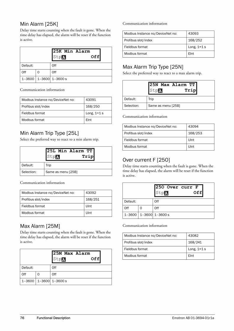
76 Functional Description Emotron AB 01-3694-01r1a
Min Alarm [25K]Delay time starts counting when the fault is gone. When the time delay has elapsed, the alarm will be reset if the function is active.
Communication information
Min Alarm Trip Type [25L]Select the preferred way to react to a min alarm trip.
Communication information
Max Alarm [25M]Delay time starts counting when the fault is gone. When the time delay has elapsed, the alarm will be reset if the function is active.
Communication information
Max Alarm Trip Type [25N]Select the preferred way to react to a max alarm trip.
Communication information
Over current F [25O]Delay time starts counting when the fault is gone. When the time delay has elapsed, the alarm will be reset if the function is active.
Communication information
Default: Off
Off 0 Off
1–3600 1–3600 1–3600 s
Modbus Instance no/DeviceNet no: 43091
Profibus slot/index 168/250
Fieldbus format Long, 1=1 s
Modbus format EInt
Default: Trip
Selection: Same as menu [25B]
Modbus Instance no/DeviceNet no: 43092
Profibus slot/index 168/251
Fieldbus format UInt
Modbus format UInt
Default: Off
Off 0 Off
1–3600 1–3600 1–3600 s
25K Min AlarmStp OffA
25L Min Alarm TTStp TripA
25M Max AlarmStp OffA
Modbus Instance no/DeviceNet no: 43093
Profibus slot/index 168/252
Fieldbus format Long, 1=1 s
Modbus format EInt
Default: Trip
Selection: Same as menu [25B]
Modbus Instance no/DeviceNet no: 43094
Profibus slot/index 168/253
Fieldbus format UInt
Modbus format UInt
Default: Off
Off 0 Off
1–3600 1–3600 1–3600 s
Modbus Instance no/DeviceNet no: 43082
Profibus slot/index 168/241
Fieldbus format Long, 1=1 s
Modbus format EInt
25N Max Alarm TTStp TripA
25O Over curr FStp OffA

Emotron AB 01-3694-01r1a Functional Description 77
Pump [25P]Delay time starts counting when the fault is gone. When the time delay has elapsed, the alarm will be reset if the function is active.
Communication information
Over Speed [25Q]Delay time starts counting when the fault is gone. When the time delay has elapsed, the alarm will be reset if the function is active.
Communication information
11.3.7 Serial Communication [260]This function is to define the communication parameters for serial communication. There are two option boards available for serial communication, RS232/485 and fieldbus.
Comm Type [261]Select RS232/485 [262] or Fieldbus [263].
RS232/485 [262]Press Enter to set up the parameters for RS232/485 commu-nication.
Baudrate [2621]Set the baud rate for the communication.
Address [2622]Enter the unit address for the VSD.
Default: Off
Off 0 Off
1–3600 1–3600 1–3600 s
Modbus Instance no/DeviceNet no: 43095
Profibus slot/index 168/254
Fieldbus format Long, 1=1 s
Modbus format EInt
Default: Off
Off 0 Off
1–3600 1–3600 1–3600 s
Modbus Instance no/DeviceNet no: 43096
Profibus slot/index 169/0
Fieldbus format Long, 1=1 s
Modbus format EInt
25P PumpStp OffA
25Q Over speedStp OffA
Default: RS232/485
RS232/485
0 RS232/485 selected
Fieldbus 1 Fieldbus selected
Default: 9600
2400 0
Selected baud rate
4800 1
9600 2
19200 3
38400 4
NOTE: This address is only used for the isolated RS232/485 option.
Default: 1
Selection: 1–247
�261 Com TypeStp RS232/485A
262 RS232/485Stp
�2621 BaudrateStp 9600A
�2622 AddressStp 1A

78 Functional Description Emotron AB 01-3694-01r1a
Fieldbus [263]Press Enter to set up the parameters for fieldbus communi-cation.
Address [2631]Enter the unit address of the VSD.
Size of data [2632]Enter the size of data process data (cyclic data).
Read/Write [2633]Select read/write to control the inverter over a fieldbus net-work.
Interrupt [264]Select interrupt function for the communication.
Communication information
FB Status [269]Sub menus showing status of fieldbus parameters. Please see the Fieldbus manual for detailed information.
Default: 62
Range: Profibus 0–126, DeviceNet 0–63
Node address valid for Profibus and DeviceNet
Default: 4
Range: 1–16
Default: RW
RW 0
R 1
Valid for process data. Select R (read only) for logging proc-ess without writing process data. Select RW in normal cases to control inverter.
Default: Warning
Off 0 No interrupt safeguard active.
263 FieldbusStpA
�2631 AddressStp 62A
�2632 SizeOfDataStp 4A
�2633 Read/WriteStp RWA
264 InterruptStp WarningA
Trip 1
RS232/485 selected:The main product will trip if there is no communication for 15 seconds.Fieldbus selected: The main product will trip if:1. The internal communication between the control board and fieldbus option is lost for 15 s.2. If a serious network error has occurred.
Warning 2
RS232/485 selected:The main product will give a warning if there is no communication for 15 seconds.Fieldbus selected: The main product will give a warning if:1. The internal communication between the control board and fieldbus option is lost for 15 s.2. If a serious network error has occurred.
Modbus Instance no/DeviceNet no: 43037
Profibus slot/index 168/196
Fieldbus format UInt
Modbus format UInt
269 FB StatusStp

Emotron AB 01-3694-01r1a Functional Description 79
11.4 Process & Application Parameters [300]
This menu contains parameters to view or set the reference value. These parameters are mainly of the types which are often adjusted to obtain optimum process or machine per-formance. Therefore up to four parameter sets (A, B, C and D) can be stored and selected when the application condi-tions require different settings. These parameter sets can be selected (also during run) via the keyboard, the terminals (selected digital inputs) or via the serial communications. The name of the active set is indicated by a letter in front of each parameter value on the display. It can also be read in the FI Status [721].
The read-out depends on the selected controller mode:
11.4.1 Set/View Reference Value [310]
View reference valueAs default the menu [310] is in view operation. The value of the active reference signal is displayed. The value is displayed according to the process unit selected in menu [322].
Set reference valueIf the function Reference Control [214] is programmed: Ref Control = Keyboard, the reference value must be set in menu [310] with the + and - keys on the control panel. The used ramp times used for this function are according to the set Acc MotPot [333] and Dec MotPot [334]. Menu [300] displays on-line the actual reference value according to the Mode Settings in Table 21.
Communication information
11.4.2 Process Settings [320]With these functions, the VSD can be set up to fit the appli-cation. Different functions will ALL use the units that are standard in the process e.g. bar, rpm or even a user-defined name. This makes it possible to easily set up the VSD for the required process requirements, as well as for copying the range of a feedback sensor to set up the Process Value Mini-mum and Maximum in order to establish accurate actual process information.
Process Source [321]Select the signal source for the process unit (value). The Process Source can be set to act as a function of the reference signal on AnIn F(AnIn), a function of the motor speed F(Speed), a function of the shaft torque F(Torque) or as a function of a reference value from serial communication F(Bus). The right function to select depends on the charac-teristics and behaviour of the process.
If the selection Speed or Torque is set the VSD will use the actual speed or torque as reference values.
ExampleAn axial fan is speed-controlled and there is no feedback sig-nal available. The process needs to be controlled within fixed process values in “m3/hr” and a process read-out of the air flow is needed. The characteristic of this fan is that the air flow is linearly related to the actual speed. So by selecting F(Speed) as the Process Source, the process can easily be controlled.
The selection F(xx) indicates that a process unit and scaling is needed. This makes it possible to e.g. use pressure sensors to measure flow etc. If F(AnIn) is selected, the source is automatically connected to the AnIn which has Process Value as selectes.
Table 21
Mode Read-out: Resolution
Frequency Mode rpm 4 digits
PID Controller % 3 digits
Speed rpm 4 digits
Torque % 3 digits
Process ReferenceDepends on selected unit in [322]
3 digits
Process ValueDepends on selected unit in [322]
3 digits
Default: 0 rpm
Dependent on:Process Source [321] and Process Unit [322]
Speed mode Min speed - max speed
Other modesMin according to menu [324] - max accord-ing to menu [325]
310 Set/View RefStp 0rpm
Modbus Instance no/DeviceNet no: 42991
Profibus slot/index 168/150
Fieldbus format Long
Modbus format EInt
Default: Speed
F(AnIn) 0 Function of analogue input
Speed 1
Torque 2
PT100 3
F(Speed) 4 Function of speed
F(Torque) 5 Function of torque
F(Bus) 6 Function of communication
321 Proc SourceStp SpeedA

80 Functional Description Emotron AB 01-3694-01r1a
Communication information
Process Unit [322]
Communication information
User-defined Unit [323]This menu is only displayed if User is selected in menu [322]. The function enables the user to define a unit with six symbols. Use the Prev and Next key to move the cursor to required position. Then use the + and - keys to scroll down the character list. Confirm the character by moving the cur-sor to the next position by pressing the Next key.
Modbus Instance no/DeviceNet no: 43302
Profibus slot/index 169/206
Fieldbus format UInt
Modbus format UInt
Default: rpm
Off 0 No unit selection
% 1 Percentage of Maximum Frequency
°C 2 Degrees Centigrade
°F 3 Degrees Fahrenheit
bar 4 bar
Pa 5 Pascal
Nm 6 Torque
Hz 7 Frequency
rpm 8 Revolutions per minute
m3/h 9 Cubic meters per hour
gal/h 10 Gallons per hour
ft3/h 11 Cubic feet per hour
User 12 User defined unit
Modbus Instance no/DeviceNet no: 43303
Profibus slot/index 169/207
Fieldbus format UInt
Modbus format UInt
Character No. for serial
comm.Character
No. for serial comm.
Space 0 m 58
0–9 1–10 n 59
A 11 ñ 60
322 Proc UnitStp rpmA
B 12 o 61
C 13 ó 62
D 14 ô 63
E 15 p 64
F 16 q 65
G 17 r 66
H 18 s 67
I 19 t 68
J 20 u 69
K 21 ü 70
L 22 v 71
M 23 w 72
N 24 x 73
O 25 y 74
P 26 z 75
Q 27 å 76
R 28 ä 77
S 29 ö 78
T 30 ! 79
U 31 ¨ 80
Ü 32 # 81
V 33 $ 82
W 34 % 83
X 35 & 84
Y 36 · 85
Z 37 ( 86
Å 38 ) 87
Ä 39 * 88
Ö 40 + 89
a 41 , 90
á 42 - 91
b 43 . 92
c 44 / 93
d 45 : 94
e 46 ; 95
é 47 < 96
ê 48 = 97
ë 49 > 98
f 50 ? 99
g 51 @ 100
Character No. for serial
comm.Character
No. for serial comm.

Emotron AB 01-3694-01r1a Functional Description 81
Example:Create a user unit named kPa.
1. When in the menu [323] press Next to move the cursor to the rightmost position.
2. Press the + key until the character k is displayed.
3. Press Next.
4. Then press the + key until P is displayed and confirm with Next.
5. Repeat until you have entered kPa.
Communication information
When sending a unit name you send one character at a time starting at the rightmost position.
Process Min [324]This function sets the minimum process value allowed.
Communication information
Process Max [325]This menu is not visible when speed, frequency and torque are selected. The function sets the value of the maximum process value allowed.
Communication information
Ratio [326]This menu is not visible when speed, frequency or torque is selected. The function sets the ratio between the actual proc-ess value and the motor speed so that it has an accurate proc-ess value when no feedback signal is used. See Fig. 64.
h 52 ^ 101
i 53 _ 102
í 54 ° 103
j 55 2 104
k 56 3 105
l 57
Default: No characters shown
Modbus Instance no/DeviceNet no:
433044330543306433074330843309
Profibus slot/index
169/208169/209169/210169/211169/212169/213
Fieldbus format UInt
Modbus format UInt
Character No. for serial
comm.Character
No. for serial comm.
323 User UnitStpA
Default: 0
Range: 0.000-10000
Modbus Instance no/DeviceNet no: 43310
Profibus slot/index 169/214
Fieldbus format Long, 1=0.001
Modbus format EInt
Default: 0
Range: 0.000-10000
Modbus Instance no/DeviceNet no: 43311
Profibus slot/index 169/215
Fieldbus format Long, 1=0.001
Modbus format EInt
Default: Linear
Linear 0
Quadratic 1
324 Process MinStp 0A
325 Process MaxStp 0A
326 RatioStp LinearA

82 Functional Description Emotron AB 01-3694-01r1a
Communication information
Fig. 64 Ratio
F(Value), Process Min [327]This function is used for scaling if no sensor is used. It offers you the possibility of increasing the process accuracy by scal-ing the process values. The process values are scaled by link-ing them to known data in the VSD. With F(Value), Proc Min the precise value at which the entered Process Min [524] is valid can be entered.
Communication information
F(Value), Process Max [328]This function is used for scaling if no sensor is used. It offers you the possibility of increasing the process accuracy by scal-ing the process values. The process values are scaled by link-ing them to known data in the VSD. With F(Value), Proc Max the precise value at which the entered Process Max [525] is valid can be entered.
Communication information
ExampleA conveyor belt is used to transport bottles. The required bottle speed needs to be within 10 to 100 bottles/s. Process characteristics:
10 bottles/s = 150 rpm100 bottles/s = 1490 rpmThe amount of bottles is linearly related to the speed of the conveyor belt.
Set-up:
Process Min [324] = 10Process Max [325] = 100Ratio [326] = linearF(Value), ProcMin [327] = 150F(Value), ProcMax [328] = 1490
With this set-up, the process data is scaled and linked to known values which results in an accurate control.
Modbus Instance no/DeviceNet no: 43312
Profibus slot/index 169/216
Fieldbus format UInt
Modbus format UInt
NOTE: If Speed or Torque is chosen in menu [321] Proc Source, this menu is hidden and using 321/331.
Default: Min
Min -1 Min
Max -2 Max
0.000-10000
0-10000 0.000-10000
Modbus Instance no/DeviceNet no: 43313
Profibus slot/index 169/217
Fieldbus format Long, 1=1 rpm
Modbus format EInt
Ratio=Linear
Ratio=Quadratic
Process
Process
Process
Min Max
unit
Max [325]
Min [324]
Speed [341]
Speed
Speed [343]
327 F(Val) PrMinStp MinA
NOTE: If Speed or Torque is chosen in menu [321] Proc Source, this menu is hidden and using 321/331
Default: Min
Min -1 Min
Max -2 Max
0.000-10000
0-10000 0.000-10000
Modbus Instance no/DeviceNet no: 43314
Profibus slot/index 169/218
Fieldbus format Long, 1=1 rpm
Modbus format EInt
328 F(Val) PrMaxStp MaxA

Emotron AB 01-3694-01r1a Functional Description 83
Fig. 65
11.4.3 Start/Stop settings [330]Submenu with all the functions for acceleration, decelera-tion, starting, stopping, etc.
Acceleration Time [331]The acceleration time is defined as the time it takes for the motor to accelerate from 0 rpm to nominal motor speed.
Communication information
Fig. 66 shows the relationship between nominal motor speed/max speed and the acceleration time. The same is valid for the deceleration time.
Fig. 66 Acceleration time and maximum speed
Fig. 67 shows the settings of the acceleration and decelera-tion times with respect to the nominal motor speed.
Fig. 67 Acceleration and deceleration times
Deceleration Time [332]The deceleration time is defined as the time it takes for the motor to decelerate from nominal motor speed to 0 rpm.
Communication information
NOTE: If the Acc Time is too short, the motor is accelerated according to the Torque Limit. The actual Acceleration Time may then be longer than the value set.
Default: 10.0 s
Range: 0.50–3600 s
Modbus Instance no/DeviceNet no: 43101
Profibus slot/index 169/5
Fieldbus format Long, 1=0.01 s
Modbus format EInt
F(Value) PrMax[328]
1490
150F(Value PrMin [327]
10Process Min [324]
100Process Max [325]
Linear
Bottles/s
331 Acc TimeStp 10.0s A
Default: 10.0 s
Range: 0.50–3600 s
Modbus Instance no/DeviceNet no: 43102
Profibus slot/index 169/6
Fieldbus format Long, 1=0.01 s
Modbus format EInt
Nominal Speed
Max Speed
rpm
t10s8s(06-F12)
100% nMOT
80% nMOT
rpm
(NG_06-F11)
Nom. Speed
Acc Time [331] Dec Time [332]
332 Dec TimeStp 10.0sA

84 Functional Description Emotron AB 01-3694-01r1a
Acceleration Time Motor Potentiometer [333]It is possible to control the speed of the VSD using the motor potentiometer function. This function controls the speed with separate up and down commands, over remote signals. The MotPot function has separate ramps settings which can be set in Acc MotPot [333] and Dec MotPot [334].
If the MotPot function is selected, this is the acceleration time for the MotPot up command. The acceleration time is defined as the time it takes for the motor to accelerate from 0 rpm to nominal speed.
Communication information
Deceleration Time Motor Potentiometer [334]If the MotPot function is selected, this is the deceleration time for the MotPot down command. The time mentioned is defined as the time it takes for the motor to decelerate from nominal speed to 0 rpm.
Communication information
Acceleration Time to Minimum Speed [335]If minimum speed is used in an application, the VSD uses separate ramp times below this level. With Acc>MinSpeed [335] and Dec<MinSpeed [336] you can set the required ramp times. Short times can be used to prevent damage and excessive pump wear due too little lubrication at lower speeds. Longer times can be used to fill up a system smoothly and prevent water hammer due to rapidly exhaust-ing air from the pipe system.
If a Minimum speed is programmed, this will be the acceler-ation time from 0 rpm to the minimum speed at a run com-mand and defined as the time it takes for the motor to accelerate from 0 rpm to nominal motor speed.
Communication information
Fig. 68
Deceleration Time from Minimum Speed [336]If a minimum speed is programmed, this will be the deceler-ation time from the minimum speed to 0 rpm in a stop command and defined as the time it takes for the motor to decelerate from the nominal motor speed to 0 rpm.
NOTE: If the Dec Time is too short and the generator energy cannot be dissipated in a brake resistor, the motor is decelerated according to the overvoltage limit. The actual deceleration time may be longer than the value set.
Default: 16.0 s
Range: 0.50–3600 s
Modbus Instance no/DeviceNet no: 43103
Profibus slot/index 169/7
Fieldbus format Long, 1=0.01 s
Modbus format EInt
Default: 16.0 s
Range: 0.50–3600 s
Modbus Instance no/DeviceNet no: 43104
Profibus slot/index 169/8
Fieldbus format Long, 1=0.01
Modbus format EInt
333 Acc MotPotStp 16.0s A
334 Dec MotPotStp 16.0sA
Default: 10.0 s
Range: 0.50-3600 s
Modbus Instance no/DeviceNet no: 43105
Profibus slot/index 169/9
Fieldbus format Long, 1=0.01
Modbus format EInt
Default: 10.0 s
Range: 0.50-3600 s
335 Acc>Min SpdStp 10.0s A
time
rpm
Nom.Speed
Max speed
Min speed
[335]
[331] [332]
[336][341]
[343]
[225]
336 Dec<Min SpdStp 10.0sA

Emotron AB 01-3694-01r1a Functional Description 85
Communication information
Acceleration Ramp Type [337]Sets the type of all the acceleration ramps in a parameter set. See Fig. 69. Depending on the acceleration and deceleration requirements for the application, the shape of both the ramps can be selected. For applications where speed changes need to be started and stopped smoothly, such as a conveyor belt with materials that can drop following a quick speed change, the ramp shape can be adapted to a S-shape and pre-vent speed change shocks. For applications that are not criti-cal in this, the speed change can be fully linear over the complete range.
Communication information
Fig. 69 Shape of acceleration ramp
Deceleration Ramp Type [338]Sets the ramp type of all deceleration parameters in a param-eter set Fig. 70.
Communication information
Fig. 70 Shape of deceleration ramp
Start Mode [339]Sets the way of starting the motor when a run command is given.Start time is how quickly the motor will start after receiving the command.
Communication information
Modbus Instance no/DeviceNet no: 43106
Profibus slot/index 169/10
Fieldbus format Long, 1=0.01 s
Modbus format EInt
Default: Linear
Linear 0 Linear acceleration ramp.
S-Curve 1 S-shape acceleration ramp.
Modbus Instance no/DeviceNet no: 43107
Profibus slot/index 169/11
Fieldbus format UInt
Modbus format UInt
337 Acc RmpStp LinearA
rpm
t(NG_06-F08)
Linear
S-curve
Default: Linear
Selection: Same as menu [337]
Modbus Instance no/DeviceNet no: 43108
Profibus slot/index 169/12
Fieldbus format UInt
Modbus format UInt
Default: Fast (fixed)
Fast 0The motor flux increases gradually. The motor starts rotating immediately once the Run command is given.
Modbus Instance no/DeviceNet no: 43109
Profibus slot/index 169/13
Fieldbus format UInt
Modbus format UInt
338 Dec RmpStp LinearA
rpm
t(NG_06-F09)
Linear
S-curve
339 Start ModeStp FastA

86 Functional Description Emotron AB 01-3694-01r1a
Spinstart [33A]The spinstart will smoothly start a motor which is already rotating by catching the motor at the actual speed and con-trol it to the desired speed. If in an application, such as an exhausting fan, the motor is already rotating due to external conditions, a smooth start of the application is required to prevent excessive wear. With the spinstart=on, the actual control of the motor is delayed due to detecting the actual speed and rotatation direction, which depend on motor size, running conditions of the motor before the Spinstart, inertia of the application, etc. Depending on the motor electrical time constant and the size of the motor, it can take maxi-mum a couple of minutes before the motor is caught.
Communication information
Stop Mode [33B]When the VSD is stopped, different methods to come to a standstill can be selected in order to optimize the stop and prevent unnecessary wear, like water hammer. Stop Mode sets the way of stopping the motor when a Stop command is given.
Communication information
Brake Release Time [33C]This brake release time compensates for the time it takes to release a mechanical brake.
Communication information
Default: Off
Off 0No spinstart. If the motor is already running the VSD can trip or will start with high cur-rent.
On 1Spinstart will allow the start of a running motor without tripping or high inrush cur-rents.
Modbus Instance no/DeviceNet no: 43110
Profibus slot/index 169/14
Fieldbus format UInt
Modbus format UInt
Default: Decel
Decel 0The motor decelerates to 0 rpm according to the set deceleration time.
Coast 1 The motor freewheels naturally to 0 rpm.
Modbus Instance no/DeviceNet no: 43111
Profibus slot/index 169/15
Fieldbus format UInt
Modbus format UInt
33A SpinstartStp OffA
33B Stop ModeStp DecelA
Default: 0.00 s
Range: 0.00–3.00 s
Modbus Instance no/DeviceNet no: 43112
Profibus slot/index 169/16
Fieldbus format Long
Modbus format EInt
33C Brk ReleaseStp 0.00sA

Emotron AB 01-3694-01r1a Functional Description 87
Fig. 71 shows the relation between the four Brake functions.
• Brake Release Time [33C]
• Start Speed [33D]
• Brake Engage Time [33E]
• Brake Wait Time [33F]
The correct time setting depends on the maximum load and the properties of the mechanical brake. During the brake release time it is possible to apply extra holding torque by setting a start speed reference with the function start speed [33D].
Fig. 71 Brake Output functions
Release Speed [33D]The releas speed only operates with the brake function: brake release [33C]. The start speed is the initial speed refer-ence during the brake release time. The torque reference is initialized to 90% of TNOM to ensure that the load is held in place.
Communication information
Brake Engage Time [33E]The brake engage time is the time it takes to hold the load while the mechanical brake engages. It is also used to get a firm stop when transmissions, etc. cause “whiplash” effects. In other words, it compensates for the time it takes to engage a mechanical brake.
(NG_06-F16)
n
t
Start Speed [33D]
Mechanical Brake
Brake Relay Output
Action must take place withinthese time intervals
Brake release time [33C]
Brake engage time
Brake wait time
Off
On
Off
On
NOTE: Although this function is designed to operate a mechanical brake via the digital outputs or relays (set to brake function) controlling a mechanical brake, it can also be used without a mechanical brake and hold the load in a fixed position.
Default: 0 rpm
Range: - 4x Sync. Speed to 4x Sync.
Depend on:4xmotor sync speed, 1500 rpm for 1470 rpm motor.
33D Release SpdStp 0rpmA
Modbus Instance no/DeviceNet no: 43113
Profibus slot/index 169/17
Fieldbus format Int, 1=1 rpm
Modbus format Int, 1=1 rpm
Default: 0.00 s
Range: 0.00–3.00 s
33E Brk EngageStp 0.00sA

88 Functional Description Emotron AB 01-3694-01r1a
Communication information
Wait Before Brake Time [33F]The brake wait time is the time to hold the load, either in order to be able to speed up immediately, or to stop and engage the brake.
Communication information
Vector Brake [33G]Braking by dissipating energy in the rotor.
Communication information
11.4.4 Speeds [340]Menu with all parameters for settings regarding to speeds, such as Min/Max speeds, Jog speeds, Skip speeds.
Minimum Speed [341]Sets the minimum speed. The minimum speed will operate as an absolute lower limit. Used to ensure the motor does not run below a certain speed and to maintain a certain per-formance.
Communication information
Stop/Sleep when less than Minimum Speed [342]With this function it is possible to put the VSD in “sleep mode” when it is running at minimum speed for the length of time set, due to process value feedback or a reference value that corresponds to a speed lower than the min speed set. The VSD will go into sleep mode after programmed time. When the reference signal or process value feedback raises the required speed value above the min speed value, the VSD will automatically wake up and ramp up to the required speed.
Communication information
Modbus Instance no/DeviceNet no: 43114
Profibus slot/index 169/18
Fieldbus format Long
Modbus format EInt
Default: 0.00 s
Range: 0.00–30.0 s
Modbus Instance no/DeviceNet no: 43115
Profibus slot/index 169/19
Fieldbus format Long
Modbus format EInt
Default: Off
Off 0Vector brake switched off. VSD brakes nor-mal with voltage limit on the DC link.
On 1Maximum VSD current (ICL) is available for braking.
Modbus Instance no/DeviceNet no: 43116
Profibus slot/index 169/20
Fieldbus format UInt
Modbus format UInt
33F Brk WaitStp 0.00sA
33G Vector BrakeStp OffA
Default: 0 rpm
Range: 0 - Max Speed
Dependent on: Set/View ref [310]
Modbus Instance no/DeviceNet no: 43121
Profibus slot/index 169/25
Fieldbus format Int, 1=1 rpm
Modbus format Int, 1=1 rpm
Default: Off
Off 0 Off
1–3600 1–3600 1–3600 s
Modbus Instance no/DeviceNet no: 43122
Profibus slot/index 169/26
Fieldbus format Long, 1=0.01 s
Modbus format EInt
341 Min SpeedStp 0rpmA
342 Stp<MinSpdStp OffA

Emotron AB 01-3694-01r1a Functional Description 89
Fig. 72
Maximum Speed [343]Sets the maximum speed at 10 V/20 mA, unless a user- defined characteristic of the analogue input is programmed. The synchronous speed (Sync-spd) is determined by the parameter motor speed [225]. The maximum speed will operate as an absolute maximum limit.
This parameter is used to prevent damage due to high speed.
Communication information
Skip Speed 1 Low [344]Within the Skip Speed range High to Low, the output speed cannot be constant in order to avoid mechanical resonance in the VSD system.
When Skip Speed Low ≤ Ref Speed ≤ Skip Speed High, then Output Speed=Skip Speed HI during deceleration and Out-put Speed=Skip Speed LO during acceleration. Fig. 73 shows the function of skip speed hi and low.
Between Skip Speed HI and LO, the speed changes with the set acceleration and deceleration times. Skipspd1 LO sets the lower value for the 1st skip range.
Communication information
Fig. 73 Skip Speed
Skip Speed 1 High [345]Skipspd1 HI sets the higher value for the 1st skip range.
Communication information
Default: Sync-Spd rpm
Range: Min Speed - 4 x Motor Sync Speed
Dependent on: Set/View ref [225]
Modbus Instance no/DeviceNet no: 43123
Profibus slot/index 169/27
Fieldbus format Int, 1=1 rpm
Modbus format Int, 1=1 rpm
NOTE: It is not possible to set the maximum speed lower than the minimum speed.
(NG_50-PC-9_1)
PID ref
Min
PID out
PID fb
[342]
speed
343 Max SpeedStp rpmA
Default: 0 rpm
Range: 0 - 4 x Motor Sync Speed
Modbus Instance no/DeviceNet no: 43124
Profibus slot/index 169/28
Fieldbus format Int
Modbus format Int
NOTE: The two Skip Speed ranges may be overlapped.
Default: 0 rpm
Range: 0 – 4 x Sync Speed
Modbus Instance no/DeviceNet no: 43125
Profibus slot/index 169/29
Fieldbus format Int
Modbus format Int
344 SkipSpd 1 LoStp 0rpmA
(NG_06-F17)
n
Skip Speed HI
Skip Speed LO
Speed Reference
345 SkipSpd 1 HiStp 0rpmA

90 Functional Description Emotron AB 01-3694-01r1a
Skip Speed 2 Low [346]The same function as menu [344] for the 2nd skip range.
Communication information
Skip Speed 2 High [347]The same function as menu [345] for the 2nd skip range.
Communication information
Jog Speed [348]This function is useful when setting up applications at low speed. The Jog Speed function is activated by one of the dig-ital inputs. The digital input must be set to the Jog function [420]. The Jog command/function will automatically gener-ate a run command as long as the Jog command/function is active. The rotation is determined by the polarity of the set Jog Speed.
ExampleIf Jog Speed = -10, this will give a Run Left command at 10 rpm regardless of RunL or RunR commands. Fig. 74 shows the function of the Jog command/function.
Communication information
Fig. 74 Jog command
11.4.5 Torques [350]Menu with all parameters for torque settings.
Maximum Torque [351]Sets the maximum torque. This Maximum Torque operates as an upper torque limit. A Speed Reference is always neces-sary to run the motor.
Communication information
Default: 0 rpm
Range: 0 – 4 x Motor Sync Speed
Modbus Instance no/DeviceNet no: 43126
Profibus slot/index 169/30
Fieldbus format Int, 1=1 rpm
Modbus format Int, 1=1 rpm
Default: 0 rpm
Range: 0 – 4 x Motor Sync Speed
Modbus Instance no/DeviceNet no: 43127
Profibus slot/index 169/31
Fieldbus format Int, 1=1 rpm
Modbus format Int, 1=1 rpm
Default: 50 rpm
Range:-4 x motor sync speed to +4 x motor sync speed
Dependent on:Defined motor sync speed. Max = 400%, normally max=VSD Imax/motor Inom x 100%.
346 SkipSpd 2 LoStp 0rpmA
347 SkipSpd 2 HiStp 0rpmA
348 Jog SpeedStp 50rpmA
Modbus Instance no/DeviceNet no: 43128
Profibus slot/index 169/32
Fieldbus format Int
Modbus format Int
Default: 120% calculated from the motor data
Range: 0–400%
Modbus Instance no/DeviceNet no: 43141
Profibus slot/index 169/45
Fieldbus format Long, 1=1%
Modbus format EInt
NOTE: 100% Torque means: INOM= IMOT. The maximum depends on the motor current and VSD max current settings, but the absolute maximum adjustment is 400%.
NOTE: The power loss in the motor will increase by the square of the torque when operating above 100%. 400% torque will result in 1600% power loss, which will increase the motor temperature very quickly.
t
t
f
(NG_06-F18)
Jog Freq
Jog com-mand
TMOT Nm( )PMOT w( )x60
nMOT rpm( )x2Π-----------------------------------------=
351 Max TorqueStp 120%A

Emotron AB 01-3694-01r1a Functional Description 91
IxR Compensation [352]This function compensates for the drop in voltage over dif-ferent resistances such as (very) long motor cables, chokes and motor stator by increasing the output voltage at a con-stant frequency. IxR Compensation is most important at low frequencies and is used to obtain a higher starting torque. The maximum voltage increase is 25% of the nominal out-put voltage. See Fig. 75.
Selecting “Automatic” will use the optimized value for the application at that moment, between the maximum voltage increase and the linear V/Hz curve. This selection automati-cally corrects the IxR Compensation for different applica-tion circumstances, such as cold start, change in viscosity, different load on conveyor, etc. and prevents unnecessary high values that can cause motor saturation. “User-Defined” can be selected when the start conditions of the application do not change and a high starting torque is always required. A fixed IxR Compensation value can be set in the menu [353].
Communication information
Fig. 75 IxR Comp at Linear V/Hz curve
IxR Comp_user [353]Only visible if User-Defined is selected in previous menu.
Communication information
Default: Off
Off 0 Function disabled
Automatic 1 Automatic compensation
User Defined
2
Modbus Instance no/DeviceNet no: 43142
Profibus slot/index 169/46
Fieldbus format UInt
Modbus format UInt
352 IxR CompStp OffA
10 20 30 40 50 Hz
f
25
%
V
100
(NG_06-F112)
IxR Comp=25%
IxR Com=0%
Default: 0.0%
Range: 0-25% x UNOM (0.1% of resolution)
Modbus Instance no/DeviceNet no: 43143
Profibus slot/index 169/47
Fieldbus format Long
Modbus format EInt
NOTE: A too high level of IxR Compensation could cause motor saturation. This can cause a “Power Fault” trip. The effect of IxR Compensation is stronger with higher power motors.
NOTE: The motor may be overheated at low speed. Therefore it is important that the Motor I2t Current [232] is set correctly.
353 IxR CompUsrStp 0.0%A
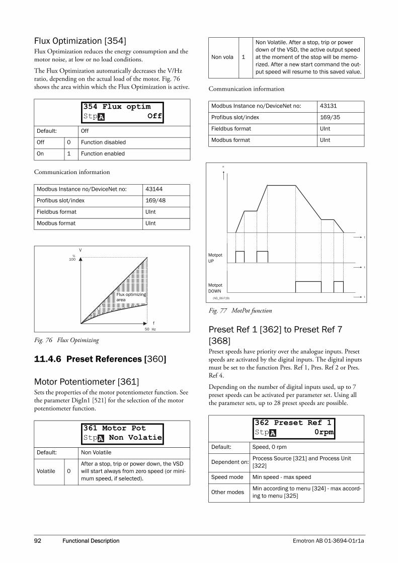
92 Functional Description Emotron AB 01-3694-01r1a
Flux Optimization [354]Flux Optimization reduces the energy consumption and the motor noise, at low or no load conditions.
The Flux Optimization automatically decreases the V/Hz ratio, depending on the actual load of the motor. Fig. 76 shows the area within which the Flux Optimization is active.
Communication information
Fig. 76 Flux Optimizing
11.4.6 Preset References [360]
Motor Potentiometer [361]Sets the properties of the motor potentiometer function. See the parameter DigIn1 [521] for the selection of the motor potentiometer function.
Communication information
Fig. 77 MotPot function
Preset Ref 1 [362] to Preset Ref 7 [368]Preset speeds have priority over the analogue inputs. Preset speeds are activated by the digital inputs. The digital inputs must be set to the function Pres. Ref 1, Pres. Ref 2 or Pres. Ref 4.
Depending on the number of digital inputs used, up to 7 preset speeds can be activated per parameter set. Using all the parameter sets, up to 28 preset speeds are possible.
Default: Off
Off 0 Function disabled
On 1 Function enabled
Modbus Instance no/DeviceNet no: 43144
Profibus slot/index 169/48
Fieldbus format UInt
Modbus format UInt
Default: Non Volatile
Volatile 0After a stop, trip or power down, the VSD will start always from zero speed (or mini-mum speed, if selected).
354 Flux optimStp OffA
50 Hz
f
%
V
100
Flux optimizing area
361 Motor PotStp Non VolatieA
Non vola 1
Non Volatile. After a stop, trip or power down of the VSD, the active output speed at the moment of the stop will be memo-rized. After a new start command the out-put speed will resume to this saved value.
Modbus Instance no/DeviceNet no: 43131
Profibus slot/index 169/35
Fieldbus format UInt
Modbus format UInt
Default: Speed, 0 rpm
Dependent on:Process Source [321] and Process Unit [322]
Speed mode Min speed - max speed
Other modesMin according to menu [324] - max accord-ing to menu [325]
t
t
n
t(NG_06-F19)
Motpot UP
Motpot DOWN
362 Preset Ref 1Stp 0rpmA

Emotron AB 01-3694-01r1a Functional Description 93
Communication information
The same settings are valid for the menus:
[363] Preset Ref 2, with default 250 rpm[364] Preset Ref 3, with default 500 rpm[365] Preset Ref 4, with default 750 rpm[366] Preset Ref 5, with default 1000 rpm[367] Preset Ref 6, with default 1250 rpm[368] Preset Ref 7, with default 1500 rpm
The selection of the presets is as in Table 22.
1)= selected if only one preset reference is active1 = active input0 = non active input
11.4.7 PID Process Control [380]The PID controller is used to control an external process via a feedback signal. The reference value can be set via analogue input AnIn1, at the Control Panel [310] by using a Preset Reference, or via serial communication. The feedback signal should be connected to an analogue input that is set to the function Process Value.
Process PID Control [381]This function enables the PID controller and defines the response to a changed feedback signal.
Communication information
PID P Gain [383]Setting the P gain for the PID controller.
Communication information
Fig. 78 Closed loop PID control
Modbus Instance no/DeviceNet no: 43132–43138
Profibus slot/index 169/36–169/42
Fieldbus format Long
Modbus format EInt
Table 22
Preset Ctrl3
Preset Ctrl2
Preset Ctrl1
Output Speed
0 0 0Analogue reference as programmed
0 0 11) Preset Ref 1
0 11) 0 Preset Ref 2
0 1 1 Preset Ref 3
11) 0 0 Preset Ref 4
1 0 1 Preset Ref 5
1 1 0 Preset Ref 6
1 1 1 Preset Ref 7
NOTE: If only Preset Ctrl3 is active, then the Preset Ref 4 can be selected. If Presets Ctrl2 and 3 are active, then the Preset Refs 2, 4 and 6 can be selected.
Default: Off
Off 0 PID control deactivated.
On 1The speed increases when the feedback value decreases. PID settings according to menus [382] to [385].
Invert 2The speed decreases when the feedback value decreases. PID settings according to menus [382] to [385].
Modbus Instance no/DeviceNet no: 43154
Profibus slot/index 169/58
Fieldbus format UInt
Modbus format UInt
Default: 1.0
Range: 0.0–30.0
Modbus Instance no/DeviceNet no: 43156
Profibus slot/index 169/60
Fieldbus format Long, 1=0.1
Modbus format EInt
NOTE: This menu is not visible if the PID Controller = Off.
381 PID ControlStp OffA
383 PID P GainStp 1.0A
+
M-
06-F95
Processreference
Processfeedback
ProcessPID
VSD
Process

94 Functional Description Emotron AB 01-3694-01r1a
PID I Time [384]Setting the integration time for the PID controller.
Communication information
Process PID D Time [385]Setting the differentiation time for the PID controller.
Communication information
11.4.8 Pump/Fan Control [390]The Pump Control functions are in menu [390]. The func-tion is used to control a number of drives (pumps, fans, etc.) of which one is always driven by the VSD.
Pump enable [391]This function will enable the pump control to set all relevant pump control functions.
Communication information
Number of Drives [392]Sets the total number of drives which are used, including the Master VSD. The setting here depends on the parameter Select Drive [393]. After the number of drives is chosen it is important to set the relays for the pump control. If the dig-ital inputs are also used for status feedback, these must be set for the pump control.
Communication information
Default: 1.00 s
Range: 0.01–300 s
Modbus Instance no/DeviceNet no: 43157
Profibus slot/index 169/61
Fieldbus format Long, 1=0.01 s
Modbus format EInt
NOTE: This menu is not visible if the PID Controller = Off.
Default: 0.00 s
Range: 0.00–30 s
Modbus Instance no/DeviceNet no: 43158
Profibus slot/index 169/62
Fieldbus format Long, 1=0.01 s
Modbus format EInt
NOTE: This menu is not visible if the PID Controller = Off.
384 PID I TimeStp 1.00sA
385 PID D TimeStp 0.00sA
Default: Off
Off 0 Pump control is switched off.
On 1
Pump control is on: - Pump control parameters [392] to [39G] appear and are activated according to default settings. - View functions [39H] to [39M] are added in the menu structure.
Modbus Instance no/DeviceNet no: 43161
Profibus slot/index 169/65
Fieldbus format UInt
Modbus format UInt
Default: 1
1-3 Number of drives if I/O Board is not used.
1-6Number of drives if 'Alternating MASTER' is used, see Select Drive [363]. (I/O Board is used.)
1-7Number of drives if 'Fixed MASTER' is used, see Select Drive [363]. (I/O Board is used.)
NOTE: Used relays must be defined as Slave Pump or Master Pump. Used digital inputs must be defined as Pump Feedback.
Modbus Instance no/DeviceNet no: 43162
Profibus slot/index 169/66
Fieldbus format UInt
Modbus format UInt
A391 Pump enableStp Off
A392 No of DrivesStp 1

Emotron AB 01-3694-01r1a Functional Description 95
Select Drive [393]Sets the main operation of the pump system. 'Sequence' and 'Runtime' are Fixed MASTER operation. 'All' means Alter-nating MASTER operation.
Communication information
Change Condition [394]This parameter determines the criteria for changing the mas-ter. This menu only appears if Alternating MASTER opera-tion is selected. The elapsed run time of each drive is monitored. The elapsed run time always determines which drive will be the 'new' master drive.
This function is only active and visible if the parameter Select Drive [393]=All.
Communication information
Default: Sequence
Sequence 0
Fixed MASTER operation:- The additional drives will be selected in sequence, i.e. first pump 1 then pump 2 etc.- A maximum of 7 drives can be used.
Run Time 1
Fixed MASTER operation:- The additional drives will be selected depending on the Run Time. So the drive with the lowest Run Time will be selected first. The Run Time is monitored in menus [39H] to [39M] in sequence. For each drive the Run Time can be reset.- When drives are stopped, the drive with the longest Run Time will be stopped first.- Maximum 7 drives can be used.
All 2
Alternating MASTER operation:- When the drive is powered up, one drive is selected as the Master drive. The selection criteria depends on the Change Condition [394]. The drive will be selected according to the Run Time. So the drive with the low-est Run Time will be selected first. The Run Time is monitored in menus [39H] to [39M] in sequence. For each drive the Run Time can be reset. - A maximum of 6 drives can be used.
Modbus Instance no/DeviceNet no: 43163
Profibus slot/index 169/67
Fieldbus format UInt
Modbus format UInt
NOTE: This menu will NOT appear if less than 3 drives are selected.
393 Select DriveStp SequenceA Default: Both
Stop 0
The Runtime of the master drive deter-mines when a master drive has to be changed. The change will only take place after a:- Power Up - Stop- Standby condition- Trip condition.
Timer 1
The master drive will be changed if the timer setting in Change Timer [395] has elapsed. The change will take place imme-diately. So during operation the additional pumps will be stopped temporarily, the 'new' master will be selected according to the Run Time and the additional pumps will be started again. It is possible to leave 2 pumps running dur-ing the change operation. This can be set with Drives on Change [396].
Both 2
The master drive will be changed if the timer setting in Change Timer [395] has elapsed. The 'new' master will be selected according to the elapsed Run Time. The change will only take place after a:- Power Up - Stop- Standby condition.- Trip condition.
Modbus Instance no/DeviceNet no: 43164
Profibus slot/index 169/68
Fieldbus format UInt
Modbus format UInt
NOTE: If the Status feedback inputs (DigIn 9 to Digin 14) are used, the master drive will be changed immediately if the feedback generates an 'Error'.
A394 Change CondStp Both

96 Functional Description Emotron AB 01-3694-01r1a
Change Timer [395]When the time set here is elapsed, the master drive will be changed. This function is only active and visible if Select Drive [393]=All and Change Cond [394]= Timer/ Both.
Communication information
Drives on Change [396]If a master drive is changed according to the timer function (Change Condition=Timer/Both [394]), it is possible to leave additional pumps running during the change opera-tion. With this function the change operation will be as smooth as possible. The maximum number to be pro-grammed in this menu depends on the number of additional drives.
Example:If the number of drives is set to 6, the maximum value will be 4. This function is only active and visible if Select Drive [393]=All.
Communication information
Upper Band [397]If the speed of the master drive comes into the upper band, an additional drive will be added after a delay time that is set in start delay [399].
Communication information
Example:Max Speed = 1500 rpmMin Speed = 300 rpmUpper Band = 10%
Start delay will be activated: Range = Max Speed to Min Speed = 1500–300 = 1200 rpm
10% of 1200 rpm = 120 rpm
Start level = 1500–120 = 1380 rpm
Fig. 79 Upper band
Lower Band [398]If the speed of the master drive comes into the lower band an additional drive will be stopped after a delay time. This delay time is set in the parameter Stop Delay [39A].
Default: 50 h
Range: 1-3000 h
Modbus Instance no/DeviceNet no: 43165
Profibus slot/index 169/69
Fieldbus format UInt, 1=1 h
Modbus format UInt, 1=1 h
Default: 0
Range: 0 to (the number of drives - 2)
Modbus Instance no/DeviceNet no: 43166
Profibus slot/index 169/70
Fieldbus format UInt
Modbus format UInt
395 Change TimerStp 50hA
A396 Drives on ChStp 0
Default: 10%
Range: 0-100% of total min speed to max speed
Modbus Instance no/DeviceNet no: 43167
Profibus slot/index 169/71
Fieldbus format Long, 1=1%
Modbus format EInt
Default: 10%
Range: 0-100% of total min speed to max speed
397 Upper BandStp 10%A
(NG_50-PC-12_1)
Flow/Pressure
Speed
Max
Min
Upper band
next pump start
Start Delay [399]
A398 Lower BandStp 10%

Emotron AB 01-3694-01r1a Functional Description 97
Communication information
Example:Max Speed = 1500 rpmMin Speed = 300 rpmLower Band = 10%
Stop delay will be activated: Range = Max Speed - Min Speed = 1500–300 = 1200 rpm
10% of 1200 rpm = 120 rpm
Start level = 300 + 120 = 420 rpm
Fig. 80 Lower band
Start Delay [399]This delay time must have elapsed before the next pump is started. A delay time prevents the nervous switching of pumps.
Communication information
Stop Delay [39A]This delay time must have elapsed before the 'top' pump is stopped. A delay time prevents the nervous switching of pumps.
Communication information
Upper Band Limit [39B]If the speed of the pump reaches the upper band limit, the next pump is started immediately without delay. If a start delay is used this delay will be ignored. Range is between 0%, equalling max speed, and the set percentage for the UpperBand [397].
Communication information
Modbus Instance no/DeviceNet no: 43168
Profibus slot/index 169/72
Fieldbus format Long, 1=1%
Modbus format EInt
Default: 0 s
Range: 0-999 s
Modbus Instance no/DeviceNet no: 43169
Profibus slot/index 169/73
Fieldbus format Long, 1=1s
Modbus format EInt
(NG_50-PC-13_1)
Speed
Max
Min
“top” pump stop
Lower band
Stop Delay [39A]
Flow/Pressure
399 Start DelayStp 0sA
Default: 0 s
Range: 0-999 s
Modbus Instance no/DeviceNet no: 43170
Profibus slot/index 169/74
Fieldbus format Long, 1=1 s
Modbus format EInt
Default: 0%
Range:0 to Upper Band level. 0% (=max speed) means that the Limit function is switched off.
Modbus Instance no/DeviceNet no: 43171
Profibus slot/index 169/75
Fieldbus format Long, 1=1%
Modbus format EInt
39A Stop DelayStp 0sA
39B Upp Band LimStp 0%A

98 Functional Description Emotron AB 01-3694-01r1a
Fig. 81 Upper band limit
Lower Band Limit [39C]If the speed of the pump reaches the lower band limit, the 'top' pump is stopped immediately without delay. If a stop delay is used this delay will be ignored. Range is from 0%, equalling min speed, to the set percentage for the Lower Band [398].
Communication information
Fig. 82 Lower band limit
Settle Time Start [39D]The settle start allows the process to settle after a pump is switched on before the pump control continues. If an addi-tional pump is started D.O.L. (Direct On Line) or Y/ , the flow or pressure can still fluctuate due to the 'rough' start/stop method. This could cause unnecessary starting and stopping of additional pumps.
During the Settle start:• PID controller is off.
• The speed is kept at a fixed level after adding a pump.
Communication information
Transition Speed Start [39E]The transition speed start is used to minimize a flow/pres-sure overshoot when adding another pump. When an addi-tional pump needs to be switched on, the master pump will slow down to the set transition speed start value, before the additional pump is started. The setting depends on the dynamics of both the master drive and the additional drives.
The transition speed is best set by trial and error.
In general:• If the additional pump has 'slow' start/stop dynamics,
then a higher transition speed should be used.
• If the additional pump has 'fast' start/stop dynamics, then a lower transition speed should be used.
Communication information
Default: 0%
Range:0 to Lower Band level. 0% (=min speed) means that he Limit function is switched off.
Modbus Instance no/DeviceNet no: 43172
Profibus slot/index 169/76
Fieldbus format Long, 1=1%
Modbus format EInt
(NG_50-PC-14_2)
Speed
Max
Min
Upper band
Start Delay [399]
Upper band limit [39B]
next pump startsimmediately
Flow/Pressure
A39C Low Band LimStp 0%
(NG_50-PC-15_2)
Speed
Max
MinLower band
Stop Delay [39A]
Lower band limit [39C]
“top” pump stops immediately
Flow/Pressure
Default: 0 s
Range: 0-999 s
Modbus Instance no/DeviceNet no: 43173
Profibus slot/index 169/77
Fieldbus format Long, 1=1 s
Modbus format EInt
Default: 60%
Range: 0-100% of total min speed to max speed
Modbus Instance no/DeviceNet no: 43174
Profibus slot/index 169/78
Fieldbus format Long, 1=1%
Modbus format EInt
Δ
A39D Settle StartStp 0s
39E TransS StartStp 60%A

Emotron AB 01-3694-01r1a Functional Description 99
ExampleMax Speed = 1500 rpmMin Speed = 200 rpmTransS Start = 60%
When an additional pump is needed, the speed will be con-trolled down to min speed + (60% x (1500 rpm - 200 rpm)) = 200 rpm + 780 rpm = 980 rpm. When this speed is reached, the additional pump with the lowest run time hours will be switched on.
Fig. 83 Transition speed start
Fig. 84 Effect of transition speed
Settle Time Stop [39F]The settle stop allows the process to settle after a pump is switched off before the pump control continues. If a addi-tional pump is stopped D.O.L. (Direct On Line) or Y/ , the flow or pressure can still fluctuate due to the 'rough' start/stop method. This could cause unnecessary starting and stopping of additional pumps.
During the Settle stop:• PID controller is off.
• the speed is kept at a fixed level after stopping a pump
Communication information
Transition Speed Stop [39G]The transition speed stop is used to minimize a flow/pres-sure overshoot when shutting down an additional pump. The setting depends on the dynamics of both the master drive and the additional drives.
In general:• If the additional pump has 'slow' start/stop dynamics,
then a higher transition speed should be used.
• If the additional pump has 'fast' start/stop dynamics, then a lower transition speed should be used.
Communication information
ExampleMax Speed = 1500 rpmMin Speed = 200 rpmTransS Start = 60%
When less additional pumps are needed, the speed will be controlled up to min speed + (60% x (1500 rpm - 200 rpm)) = 200 rpm + 780 rpm = 980 rpm. When this speed is reached, the additional pump with the highest run time hours will be switched off.
Default: 0 s
Range: 0–999 s
(NG_50-PC-16_1)
Speed
Actual
Trans
Min
Switch on procedure starts
Additional pump
Master pump
Flow/PressureActual startcommand of nextpump (RELAY)
(NG_50-PC-17_1)
Flow/Pressure Transition speeddecreases overshoot
Time
Δ
A39F Settle StopStp 0s
Modbus Instance no/DeviceNet no: 43175
Profibus slot/index 169/79
Fieldbus format Long, 1=1 s
Modbus format EInt
Default: 60%
Range: 0-100% of total min speed to max speed
Modbus Instance no/DeviceNet no: 43176
Profibus slot/index 169/80
Fieldbus format Long, 1=1%
Modbus format EInt
39G TransS StopStp 60%A

100 Functional Description Emotron AB 01-3694-01r1a
Fig. 85 Transition speed stop
Run Times 1-6 [39H] to [39M]
Communication information
Reset Run Times 1-6 [39H1] to [39M1]
Communication information
Pump Status [39N]
Unit: h:m (hours:minutes)
Range: 0h:0m–65535h:59m.
Modbus Instance no/DeviceNet no:
31051 hours, 31052 minutes, 31054 hours, 31055 minutes, 31057 hours, 31058 minutes, 31060 hours, 31061 minutes, 31063 hours, 31064 minutes, 31066 hours, 31067 minutes
Profibus slot/index121/195, 121/198, 121/201, 121/204, 121/207, 121/210
Fieldbus format UInt
Modbus format UInt
Default: No
No 0
Yes 1
Modbus Instance no/DeviceNet no: 38–43, pump 1 -6
Profibus slot/index 0/37–0/42
Fieldbus format UInt
Modbus format UInt
Speed
Max
Trans
Actual
Min
Actual shut down of pump
Master pump
Switch off procedure starts
Additional pump
Flow/Pressure
A39H Run Time 1Stp h:mm
A39H1 Rst Run Tm1Stp No
Indication Description
CControl, master pump, only when alternating master is used
D Direct control
O Pump is off
E Pump error
39N Pump 123456Stp OCD A

Emotron AB 01-3694-01r1a Functional Description 101
11.5 Load Monitor and Process Protection [400]
11.5.1 Load Monitor [410]The monitor functions enable the VSD to be used as a load monitor. Load monitors are used to protect machines and processes against mechanical overload and underload, e.g. a conveyer belt or screw conveyer jamming, belt failure on a fan and a pump dry running.
Alarm Select [411]Selects the types of alarms that are active.
Communication information
Alarm Trip [412]Selects which alarm must cause a trip to the VSD.
Communication information
Ramp Alarm [413]This function inhibits the (pre) alarm signals during acceler-ation/deceleration of the motor to avoid false alarms.
Communication information
Alarm Start Delay [414]This parameter is used if, for example, you want to override an alarm during the start-up procedure.
Sets the delay time after a run command, after which the alarm may be given.
• If Ramp Alarm=On. The start delay begins after a RUN command.
• If Ramp Alarm=Off. The start delay begins after the acceleration ramp.
Communication information
Default: Off
Off 0No alarm functions active.NOTE: The menus [412-415] are not visible.
Min 1
Min Alarm active. The alarm output func-tions as an underload alarm.NOTE: The menus [416-417] are not visible.
Max 2
Max Alarm active. The alarm output func-tions as an overload alarm.NOTE: The menus [418-419] are not visible.
Max+Min 3Both Max and Min alarm are active. The alarm outputs function as overload and underload alarms.
Modbus Instance no/DeviceNet no: 43321
Profibus slot/index 169/225
Fieldbus format UInt
Modbus format UInt
Default: Off
Selection: Same as in menu [411]
411 Alarm SelectStp OffA
412 Alarm tripStp OffA
Modbus Instance no/DeviceNet no: 43322
Profibus slot/index 169/226
Fieldbus format UInt
Modbus format UInt
Default: Off
On 0(Pre) alarms active during acceleration/deceleration.
Off 1(Pre) alarms are inhibited during accelera-tion/deceleration.
Modbus Instance no/DeviceNet no: 43323
Profibus slot/index 169/227
Fieldbus format UInt
Modbus format UInt
Default: 0
Range: 0-3600 s
Modbus Instance no/DeviceNet no: 43324
Profibus slot/index 169/228
Fieldbus format Long, 1=1 s
Modbus format EInt
413 Ramp AlarmStp OffA
414 Start DelayStp 2sA

102 Functional Description Emotron AB 01-3694-01r1a
Load Type [415]In this menu you select monitor type according to the load characteristic of your application. By selecting the required monitor type, the overload and underload alarm function can be optimized according to the load characteristic.
When the application has a constant load over the whole speed range, i.e. extruder or screw compressor, the load type can be set to basic.
When the load of the application does vary over the speed range i.e. centrifugal pump or a fan, the load type can be set to load curve to achieve accurate protection over the whole speed range.
Fig. 86
Communication information
Max Alarm [416]
Max Alarm Margin [4161]The max alarm margin sets the allowed deviation level for generating an overload alarm. This margin will be added to the measured load value during the auto set.
Communication information
Max Alarm delay [4162]Sets the delay time between the first occurrence of max alarm condition and after when the alarm is given.
Communication information
Max Pre Alarm [417]
Max Pre AlarmMargin [4171]The max pre alarm margin sets the allowed deviation level for generating an overload pre alarm. This margin will be added to the measured load value during the auto set. Only used when auto set is used.
Default: Basic
Basic 0
Uses a fixed maximum and minimum load level over the full speed range. Can be used in situations where the torque is independ-ent of the speed.
Load Curve
1Uses the measured actual load characteris-tic of the process over the speed range.
Modbus Instance no/DeviceNet no: 43325
Profibus slot/index 169/229
Fieldbus format UInt
Modbus format UInt
Basic
Load curve
Load
Speed
Max Alarm
Min Alarm
415 Load TypeStp BasicA
Default: 15%
Range: 0–400%
Modbus Instance no/DeviceNet no: 43326
Profibus slot/index 169/230
Fieldbus format Long, 1=1%
Modbus format EInt
Default: 0.1 s
Range: 0-90 s
Modbus Instance no/DeviceNet no: 43330
Profibus slot/index 169/234
Fieldbus format Long, 1=0.1 s
Modbus format EInt
Default: 10%
Range: 0–400%
4161 MaxAlarmMarStp 15%A
4162 MaxAlarmDelStp 0.1sA
4171 MaxPreAlMarStp 10%A

Emotron AB 01-3694-01r1a Functional Description 103
Communication information
Max Pre Alarm delay [4172]Sets the delay time between the first occurrence of max pre alarm condition and after when the alarm is given.
Communication information
Min Pre Alarm [418]
Min Pre Alarm Margin [4181]Only used when auto set is used.
Communication information
Min Pre Alarm Response delay [4182]Sets the delay time between the first occurrence of min pre alarm condition and after when the alarm is given.
Communication information
Min Alarm [419]
Min Alarm Margin [4191]Only used when auto set is used.
Communication information
Min Alarm Response delay [4192]Sets the delay time between the first occurrence of min alarm condition and after when the alarm is given.
Communication information
Modbus Instance no/DeviceNet no: 43327
Profibus slot/index 169/231
Fieldbus format Long, 1=0.1%
Modbus format EInt
Default: 0.1 s
Range: 0–90 s
Modbus Instance no/DeviceNet no: 43331
Profibus slot/index 169/235
Fieldbus format Long, 1=0.1 s
Modbus format EInt
Default: 10%
Range: 0-400%
Modbus Instance no/DeviceNet no: 43328
Profibus slot/index 169/232
Fieldbus format Long, 1=1%
Modbus format EInt
4172 MaxPreAlDelStp 0.1sA
4181 MinPreAlMarStp 10%A
Default: 0.1 s
Range: 0-90 s
Modbus Instance no/DeviceNet no: 43332
Profibus slot/index 169/236
Fieldbus format Long, 1=0.1 s
Modbus format EInt
Default: 15%
Range: 0-400%
Modbus Instance no/DeviceNet no: 43329
Profibus slot/index 169/233
Fieldbus format Long, 1=1%
Modbus format EInt
Default: 0.1 s
Range: 0-90 s
Modbus Instance no/DeviceNet no: 43333
Profibus slot/index 169/237
Fieldbus format Long, 1=0.1 s
Modbus format EInt
4182 MinPreAlDelStp 0.1sA
4191 MinAlarmMarStp 15%A
4192 MinAlarmDelStp 0.1sA

104 Functional Description Emotron AB 01-3694-01r1a
Autoset Alarm [41A]When load type [415] is set to basic, the auto set function sets the actual load level at 100% and accompanying alarm levels automatically. When load type [415] is set to load curve, the auto set function will perform a test run to meas-ure the actual load at the defined 9 sample speed references. The VSD will then run the motor from min to max speed.
Communication information
The default set levels for the (pre)alarms are:
These default set levels can be manually changed in menus [416] to [419]. After execution the message “Autoset OK!” is displayed for 1s and the selection reverts to “No”.
Normal Load [41B]This menu is only visible when basic load is selected as load type [415]. Set the level on which the trip will occur.
Communication information
Load Curve [41C]This menu is only visible when load curve is selected as load type [415].
The function should be used only for loads with quadratic load curve.
Load Curve 1-9 [41C1]-[41C9]The measured load curve is based on 9 stored samples. The curve starts at minimum speed and ends at maximum speed, the range in between is divided into 7 equal steps. The meas-ured values of each sample are displayed in [41C1] to [41C9] and can be adapted manually. The value of the 1st sampled value on the load curve is displayed.
Communication information
WARNING: When auto test does a test run the motor and application/machine will start!
Default: No
No 0
Yes 1
Modbus Instance no/DeviceNet no: 43334
Profibus slot/index 169/238
Fieldbus format UInt
Modbus format UInt
OverloadMax Alarm menu [4161] + [41B]
Max Pre Alarm menu [4171] + [41B]
UnderloadMin Pre Alarm menu [41B] - [4181]
Min Alarm menu [41B] - [4191]
Default: 100%
Range: 0-400% of max torque
41A AutoSet AlrmStp NoA
41B Normal LoadStp 100%A
Modbus Instance no/DeviceNet no: 43334
Profibus slot/index 169/239
Fieldbus format Long, 1=1%
Modbus format EInt
Default: 100%
Range: 0–400% of max torque
Modbus Instance no/DeviceNet no:
43336%, 43337 rpm, 43338%, 43339 rpm, 43340%, 43341 rpm, 43342%, 43343 rpm, 43344%, 43345 rpm, 43346%, 43347 rpm, 43348%, 43349 rpm, 43350%, 43351 rpm, 43352%, 43353 rpm
Profibus slot/index
169/240, 169/242, 169/244, 169/246, 169/248, 169/250, 169/252, 169/254, 169/170/1
Fieldbus format Long
Modbus format EInt
NOTE: These values are read only and cannot be changed.
41C1 Load Curve1Stp 0rpm 100%A

Emotron AB 01-3694-01r1a Functional Description 105
Fig. 87
11.5.2 Process Protection [420]Submenu with settings regarding protection functions for the VSD and the motor.
Low Voltage Override [421]If a dip in the mains supply occurs and the low voltage over-ride function is enabled, the VSD will automatically decrease the motor speed to keep control of the application and prevent an under voltage trip until the input voltage rises again. Therefore the rotating energy in the motor/load is used to keep the DC link voltage level at the override level, for as long as possible or until the motor comes to a stand-still. This is dependent on the inertia of the motor/load combination and the load of the motor at the time the dip occurs, see Fig. 88.
Communication information
Fig. 88 Low voltage override
Rotor locked [422]With the rotor locked function enabled, the VSD will pro-tect the motor and application when this is stalled whilst increasing the motor speed from standstill. This protection will coast the motor to stop and indicate a fault when the Torque Limit has been active at very low speed for more than 5 seconds.
Communication information
Default: On
Off 0At a voltage dip the low voltage trip will pro-tect.
On 1At mains dip, VSD ramps down until voltage rises.
Modbus Instance no/DeviceNet no: 43361
Profibus slot/index 170/10
Fieldbus format UInt
Modbus format UInt
100%
Min Speed Speed Max Speed
Min Alarm [419]
Max Alarm [416]MeasuredLoad Curve
=Samples
rpm
421 Low Volt ORStp OnA
NOTE: During the low voltage override the LED trip/limit blinks.
Default: Off
Off 0 No detection
On 1VSD will trip when locked rotor is detected. Trip message “Locked Rotor”.
Modbus Instance no/DeviceNet no: 43362
Profibus slot/index 170/11
Fieldbus format UInt
Modbus format UInt
t
t(06-F60new)
Override level
Speed
DC link voltage
�
422 Rotor lockedStp OffA

106 Functional Description Emotron AB 01-3694-01r1a
Motor lost [423]With the motor lost function enabled, the VSD is able to detect a fault in the motor circuit: motor, motor cable, ther-mal relay or output filter. Motor lost will cause a trip, and the motor will coast to standstill, when a missing motor phase is detected during a period of 5 s.
Communication information
Overvolt control [424]Used to switch off the overvoltage control function when only braking by brake chopper and resistor is required. The overvoltage control function, controls the braking torque sot that the DC link voltage level is controlled at a high, but safe, level.
Communication information
11.6 I/Os and Virtual Connections [500]
Main menu with all the settings of the standard inputs and outputs of the VSD.
11.6.1 Analogue Inputs [510]Submenu with all settings for the analogue inputs.
AnIn1 Function [511] Sets the function for Analogue input 1. Scale and range are defined by AnIn1 Advanced settings [513].
Communication information
Adding analogue inputsIf more then one analogue input is set to the same function, the values of the inputs can be added together. In the follow-ing examples we assume that Process Source [321] is set to Speed.
Example 1: Add signals with different weight (fine tuning).
Signal on AnIn1 = 10 mASignal on AnIn2 = 5 mA
[511] AnIn1 Function = Process Ref.[512] AnIn1 Setup = 4-20 mA[5134] AnIn1 Function Min = Min (0 rpm)[5136] AnIn1 Function Max = Max (1500 rpm)
Default: Off
Off 0Function switched off to be used if no motor or very small motor connected.
Trip 1VSD will trip when the motor is discon-nected. Trip message “Motor Lost”.
Modbus Instance no/DeviceNet no: 43363
Profibus slot/index 170/12
Fieldbus format UInt
Modbus format UInt
Default: On
On 0 Overvoltage control activated
Off 1 Overvoltage control off
Modbus Instance no/DeviceNet no: 43364
Profibus slot/index 170/13
Fieldbus format UInt
Modbus format UInt
423 Motor lostStp OffA
�
424 Over Volt CtlStp OnA
Default: Process Ref
Off 0 Input is not active
Max Speed 1 The input acts as an upper speed limit.
Max Torque
2 The input acts as an upper torque limit.
Process Val
3
The input value equals the actual process value (feedback) and is compared to the reference signal (setpoint) by the PID con-troller, or can be used to display and view the actual process value.
Process Ref
4Reference value is set for control in proc-ess units, see Process Source [321] and Process Unit [322].
Modbus Instance no/DeviceNet no: 43201
Profibus slot/index 169/105
Fieldbus format UInt
Modbus format UInt
NOTE: When AnInX Func=Off, the connected signal will still be available for Comparators [610].
511 AnIn1 FcStp Process RefA
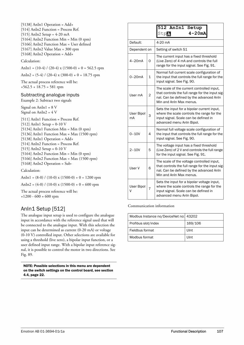
Emotron AB 01-3694-01r1a Functional Description 107
[5138] AnIn1 Operation = Add+[514] AnIn2 Function = Process Ref.[515] AnIn2 Setup = 4-20 mA[5164] AnIn2 Function Min = Min (0 rpm)[5166] AnIn2 Function Max = User defined[5167] AnIn2 Value Max = 300 rpm[5168] AnIn2 Operation = Add+
Calculation:
AnIn1 = (10-4) / (20-4) x (1500-0) + 0 = 562.5 rpm
AnIn2 = (5-4) / (20-4) x (300-0) + 0 = 18.75 rpm
The actual process reference will be:+562.5 + 18.75 = 581 rpm
Subtracting analogue inputsExample 2: Subtract two signals
Signal on AnIn1 = 8 VSignal on AnIn2 = 4 V
[511] AnIn1 Function = Process Ref.[512] AnIn1 Setup = 0-10 V[5134] AnIn1 Function Min = Min (0 rpm)[5136] AnIn1 Function Max = Max (1500 rpm)[5138] AnIn1 Operation = Add+[514] AnIn2 Function = Process Ref.[515] AnIn2 Setup = 0-10 V[5164] AnIn2 Function Min = Min (0 rpm)[5166] AnIn2 Function Max = Max (1500 rpm)[5168] AnIn2 Operation = Sub-
Calculation:
AnIn1 = (8-0) / (10-0) x (1500-0) + 0 = 1200 rpm
AnIn2 = (4-0) / (10-0) x (1500-0) + 0 = 600 rpm
The actual process reference will be:+1200 - 600 = 600 rpm
AnIn1 Setup [512]The analogue input setup is used to configure the analogue input in accordance with the reference signal used that will be connected to the analogue input. With this selection the input can be determined as current (0-20 mA) or voltage (0-10 V) controlled input. Other selections are available for using a threshold (live zero), a bipolar input function, or a user defined input range. With a bipolar input reference sig-nal, it is possible to control the motor in two directions. See Fig. 89.
Communication information
NOTE: Possible selections in this menu are dependent on the switch settings on the control board, see section 4.4, page 22.
Default: 4-20 mA
Dependent on Setting of switch S1
4–20mA 0The current input has a fixed threshold (Live Zero) of 4 mA and controls the full range for the input signal. See Fig. 91.
0–20mA 1Normal full current scale configuration of the input that controls the full range for the input signal. See Fig. 90.
User mA 2
The scale of the current controlled input, that controls the full range for the input sig-nal. Can be defined by the advanced AnIn Min and AnIn Max menus.
User Bipol mA
3
Sets the input for a bipolar current input, where the scale controls the range for the input signal. Scale can be defined in advanced menu AnIn Bipol.
0–10V 4Normal full voltage scale configuration of the input that controls the full range for the input signal. See Fig. 90.
2–10V 5The voltage input has a fixed threshold (Live Zero) of 2 V and controls the full range for the input signal. See Fig. 91.
User V 6
The scale of the voltage controlled input, that controls the full range for the input sig-nal. Can be defined by the advanced AnIn Min and AnIn Max menus.
User Bipol V
7
Sets the input for a bipolar voltage input, where the scale controls the range for the input signal. Scale can be defined in advanced menu AnIn Bipol.
Modbus Instance no/DeviceNet no: 43202
Profibus slot/index 169/106
Fieldbus format UInt
Modbus format UInt
512 AnIn1 SetupStp 4-20mAA

108 Functional Description Emotron AB 01-3694-01r1a
Fig. 89
Fig. 90 Normal full-scale configuration
Fig. 91 2–10 V/4–20 mA (Live Zero)
AnIn1 Advanced [513]
AnIn1 Min [5131] Parameter to set the minimum value of the external refer-ence signal. Only visible if [512] = User mA/V.
Communication information
AnIn1 Max [5132] Parameter to set the maximum value of the external refer-ence signal. Only visible if [512] = User mA/V.
Communication information
20 mA
100 %
100 %
n
(NG_06-F21)
10 V0-10 V
Speed
20mA
100 %
n
(NG_06-F21)
0 10 VRef
0–10 V0–20 mA
0 0mA2
100 %
n
4mA
(NG_06-F24)
10 V2 V
2–10 V
Ref
4–20 mA
NOTE: The different menus will automatically be set to either “mA” or “V”, based on the selection in AnIn 1 Setup [512].
Default: 0 V/4.00 mA
Range:0.00–20.00 mA0–10.00 V
Modbus Instance no/DeviceNet no: 43203
Profibus slot/index 169/107
Fieldbus format Long
Modbus format EInt
Default: 10.00 V/20.00 mA
Range:0.00–20.00 mA0–10.00 V
Modbus Instance no/DeviceNet no: 43204
Profibus slot/index 169/108
Fieldbus format Long
Modbus format EInt
513 AnIn1 AdvanStpA
5131 AnIn1 MinStp 0V/4.00mAA
5132 AnIn1 MaxStp 10.0V/20.00mA
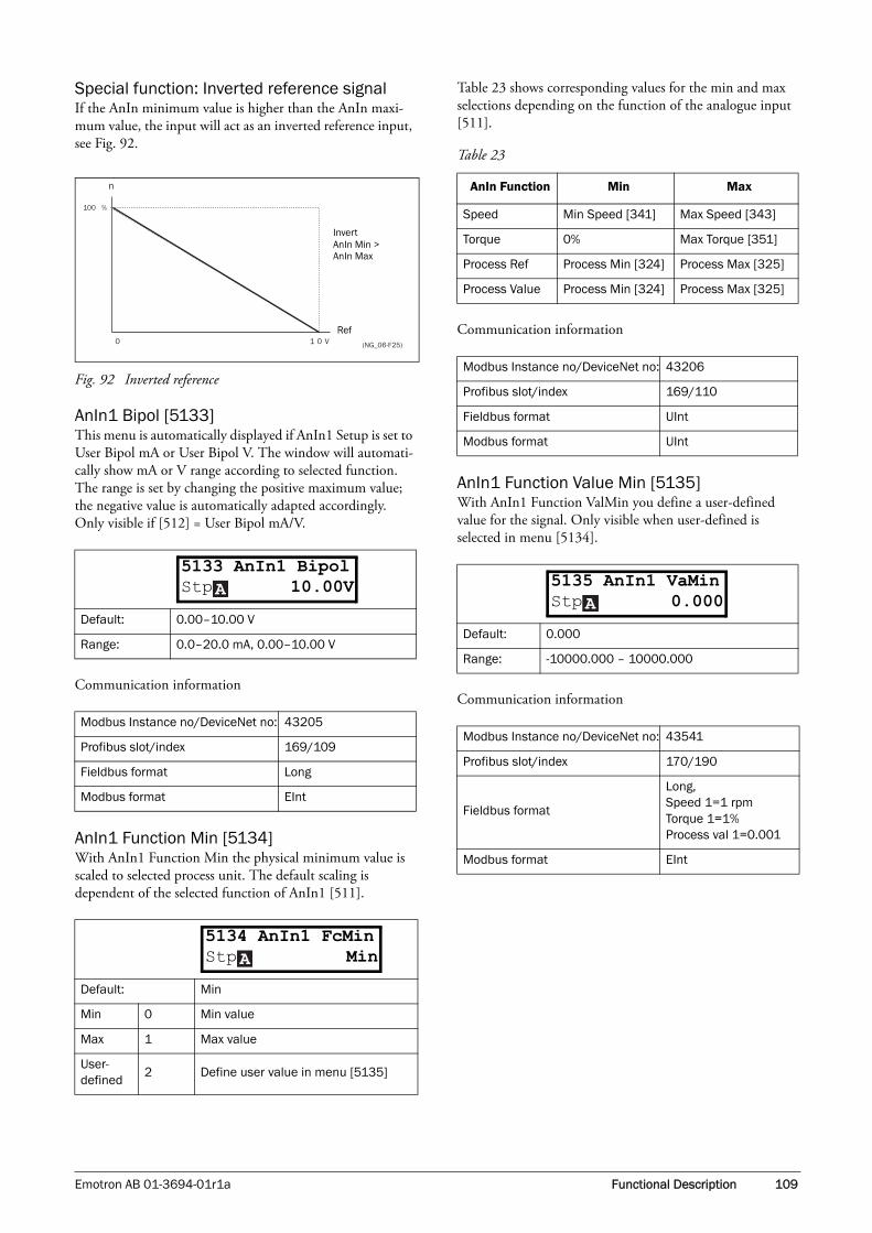
Emotron AB 01-3694-01r1a Functional Description 109
Special function: Inverted reference signalIf the AnIn minimum value is higher than the AnIn maxi-mum value, the input will act as an inverted reference input, see Fig. 92.
Fig. 92 Inverted reference
AnIn1 Bipol [5133]This menu is automatically displayed if AnIn1 Setup is set to User Bipol mA or User Bipol V. The window will automati-cally show mA or V range according to selected function. The range is set by changing the positive maximum value; the negative value is automatically adapted accordingly. Only visible if [512] = User Bipol mA/V.
Communication information
AnIn1 Function Min [5134] With AnIn1 Function Min the physical minimum value is scaled to selected process unit. The default scaling is dependent of the selected function of AnIn1 [511].
Table 23 shows corresponding values for the min and max selections depending on the function of the analogue input [511].
Communication information
AnIn1 Function Value Min [5135]With AnIn1 Function ValMin you define a user-defined value for the signal. Only visible when user-defined is selected in menu [5134].
Communication information
Default: 0.00–10.00 V
Range: 0.0–20.0 mA, 0.00–10.00 V
Modbus Instance no/DeviceNet no: 43205
Profibus slot/index 169/109
Fieldbus format Long
Modbus format EInt
Default: Min
Min 0 Min value
Max 1 Max value
User-defined
2 Define user value in menu [5135]
0 1 0 V
100 %
n
(NG_06-F25)
Invert
Ref
AnIn Min > AnIn Max
5133 AnIn1 BipolStp 10.00VA
5134 AnIn1 FcMinStp MinA
Table 23
AnIn Function Min Max
Speed Min Speed [341] Max Speed [343]
Torque 0% Max Torque [351]
Process Ref Process Min [324] Process Max [325]
Process Value Process Min [324] Process Max [325]
Modbus Instance no/DeviceNet no: 43206
Profibus slot/index 169/110
Fieldbus format UInt
Modbus format UInt
Default: 0.000
Range: -10000.000 – 10000.000
Modbus Instance no/DeviceNet no: 43541
Profibus slot/index 170/190
Fieldbus format
Long, Speed 1=1 rpmTorque 1=1%Process val 1=0.001
Modbus format EInt
5135 AnIn1 VaMinStp 0.000A

110 Functional Description Emotron AB 01-3694-01r1a
AnIn1 Function Max [5136]With AnIn1 Function Max the physical maximum value is scaled to selected process unit. The default scaling is dependent of the selected function of AnIn1 [511]. See Table 23.
Communication information
AnIn1 Function Value Max [5137]With AnIn1 Function VaMax you define a user-defined value for the signal. Only visible when user-defined is selected in menu [5136].
Communication information
Example:
Process sensor is a sensor with the following specification:
Range: 0–3 barOutput: 2–10 mA
Analogue input should be set up according to:
[512] AnIn1 Setup = User mA[5131] AnIn1 Min = 2 mA[5132] AnIn1 Max = 10 mA[5134] AnIn1 Function Min = User-defined[5135] AnIn1 VaMin = 0.000 bar[5136] AnIn 1 Function Max = User-defined[5137] AnIn1 VaMax = 3.000 bar
AnIn1 Operation [5138]
Communication information
AnIn1 Filter [5139]If the input signal is unstable (e.g. fluctuation reference value), the filter can be used to stabilize the signal. A change of the input signal will reach 63% on AnIn1 within the set AnIn1 Filter time. After 5 times the set time, AnIn1 will have reached 100% of the input change. See Fig. 93.
Communication information
Default: Min
Min 0 Min value
Max 1 Max value
User-defined
2 Define user value in menu [5137]
Modbus Instance no/DeviceNet no:
43207
Profibus slot/index 169/111
Fieldbus formatLong,Speed/Torque 1=1 rpm or %.Other 1= 0.001
Modbus format EInt
Default: 0.000
Range: -10000.000 – 10000.000
Modbus Instance no/DeviceNet no: 43551
Profibus slot/index 170/200
Fieldbus format
Long, Speed 1=1 rpmTorque 1=1%Process val 1=0.001
Modbus format EInt
NOTE: With AnIn Min, AnIn Max, AnIn Function Min and AnIn Function Max settings, loss of feedback signals (e.g. voltage drop due to long sensor wiring) can be compensated to ensure an accurate process control.
5136 AnIn1 FcMaxStp MaxA
5137 AnIn1 VaMaxStp 0.000A
Default: Add+
Add+ 0Analogue signal is added to selected func-tion in menu [511].
Sub- 1Analogue signal is subtracted from selected function in menu [511].
Modbus Instance no/DeviceNet no: 43208
Profibus slot/index 169/112
Fieldbus format UInt
Modbus format UInt
Default: 0.1 s
Range: 0.001 – 10.0 s
Modbus Instance no/DeviceNet no: 43209
Profibus slot/index 169/113
Fieldbus format Long, 1=0.001 s
Modbus format EInt
5138 AnIn1 OperStp Add+A
5139 AnIn1 FiltStp 0.1sA

Emotron AB 01-3694-01r1a Functional Description 111
Fig. 93
AnIn2 Function [514]Parameter for setting the function of Analogue Input 2.
Same function as AnIn1 Func [511].
Communication information
AnIn2 Setup [515]Parameter for setting the function of Analogue Input 2.
Same functions as AnIn1 Setup [512].
Communication information
AnIn2 Advanced [516]Same functions and submenus as under AnIn1 Advanced [513].
Communication information
AnIn3 Function [517]Parameter for setting the function of Analogue Input 3.
Same function as AnIn1 Func [511].
Communication information
AnIn3 Setup [518]Same functions as AnIn1 Setup [512].
Communication information
Default: Off
Selection: Same as in menu [511]
Modbus Instance no/DeviceNet no: 43211
Profibus slot/index 169/115
Fieldbus format UInt
Modbus format UInt
Default: 4 – 20 mA
Dependent on Setting of switch S2
Selection: Same as in menu [512].
Modbus Instance no/DeviceNet no: 43212
Profibus slot/index 169/116
Fieldbus format UInt
Modbus format UInt
AnIn change
100%
63%
Original input signal
Filtered AnIn signal
T 5 X T
514 AnIn2 FcStp OffA
515 AnIn2 SetupStp 4-20mAA
Modbus Instance no/DeviceNet no:43213–432194354243552
Profibus slot/index169/117–123170/191170/201
Default: Off
Selection: Same as in menu [511]
Modbus Instance no/DeviceNet no: 43221
Profibus slot/index 169/125
Fieldbus format UInt
Modbus format UInt
Default: 4–20 mA
Dependent on Setting of switch S3
Selection: Same as in menu [512].
Modbus Instance no/DeviceNet no: 43222
Profibus slot/index 169/126
Fieldbus format UInt
Modbus format UInt
516 AnIn2 AdvanStpA
517 AnIn3 FcStp OffA
518 AnIn3 SetupStp 4-20mAA

112 Functional Description Emotron AB 01-3694-01r1a
AnIn3 Advanced [519]Same functions and submenus as under AnIn1 Advanced [513].
Communication information
AnIn4 Function [51A]Parameter for setting the function of Analogue Input 4.
Same function as AnIn1 Func [511].
Communication information
AnIn4 Set-up [51B]Same functions as AnIn1 Setup [512].
Communication information
AnIn4 Advanced [51C]Same functions and submenus as under AnIn1 Advanced [513].
Communication information
11.6.2 Digital Inputs [520]Submenu with all the settings for the digital inputs.
Digital Input 1 [521]To select the function of the digital input.
On the standard control board there are eight digital inputs.
If the same function is programmed for more than one input that function will be activated according to “OR” logic.
Modbus Instance no/DeviceNet no:43223–432294354343553
Profibus slot/index169/127–169/133170/192170/202
Default: Off
Selection: Same as in menu [511]
Modbus Instance no/DeviceNet no: 43231
Profibus slot/index 169/135
Fieldbus format UInt
Modbus format UInt
Default: 4-20 mA
Dependent on Setting of switch S4
Selection: Same as in menu [512].
Modbus Instance no/DeviceNet no: 43232
Profibus slot/index 169/136
Fieldbus format UInt
Modbus format UInt
519 AnIn3 AdvanStpA
51A AnIn4 FcStp OffA
51B AnIn4 SetupStp 4-20mAA
Modbus Instance no/DeviceNet no:43233–432394354443554
Profibus slot/index169/137–143170/193170/203
NOTE: Additional inputs will become available when the I/O option boards are connected.
Default: RunL
Off 0 The input is not active.
Lim Switch+ 1
VSD ramps to stop and prevents rota-tion in “R” direction (clockwise), when the signal is low! NOTE: The Lim Switch+ is active low.
Lim Switch - 2
VSD ramps to stop and prevents rota-tion in “L” direction (counter clockwise) when the signal is low! NOTE: The Lim Switch- is active low.
Ext. Trip 3
Be aware that if there is nothing con-nected to the input, the VSD will trip at “External trip” immediately.NOTE: The External Trip is active low.
Stop 4Stop command according to the selected Stop mode in menu [33B].NOTE: The Stop command is active low.
51C AnIn4 AdvanStpA
521 DigIn 1 Stp RunLA

Emotron AB 01-3694-01r1a Functional Description 113
Communication information
Digital Input 2 [522] to Digital Input 8 [528]Same function as DigIn 1 [521]. Default function for DigIn 8 it is Reset. For DigIn 4 to 7 the default function is Off.
Communication information
Additional digital inputs [529] to [52H]Additional digital inputs with I/O option board installed, B1 DigIn 1 [529] - B3 DigIn 3 [52H]. B stands for board and 1 to 3 stand for the number of the board. The functions and selections are the same as DigIn 1 [521].
Communication information
Enable 5
Enable command. General start condi-tion to run the VSD. If made low during running the output of the VSD is cut off immediately, causing the motor to coast to zero speed.NOTE: If none of the digital inputs are programmed to “Enable”, the internal enable signal is active.
RunR 6Run Right command. The output of the VSD will be a clockwise rotary field.
RunL 7Run Left command. The output of the VSD will be a counter-clockwise rotary field.
Reset 9Reset command. To reset a Trip condi-tion and to enable the Autoreset func-tion.
Preset Ctrl1 10 To select the Preset Reference.
Preset Ctrl2 11 To select the Preset Reference.
Preset Ctrl3 12 To select the Preset Reference.
MotPot Up 13
Increases the internal reference value according to the set AccMotPot time [333]. Has the same function as a “real” motor potentiometer, see Fig. 77.
MotPot Down
14Decreases the internal reference value according to the set DecMotPot time [334]. See MotPot Up.
Pump1 Feedb
15Feedback input pump1 for Pump/Fan control and informs about the status of the auxiliary connected pump/fan.
Pump2 Feedb
16Feedback input pump 2 for Pump/Fan control and informs about the status of the auxiliary connected pump/fan.
Pump3 Feedb
17Feedback input pump3 for Pump/Fan control and informs about the status of the auxiliary connected pump/fan.
Pump4 Feedb
18Feedback input pump 4 for Pump/Fan control and informs about the status of the auxiliary connected pump/fan.
Pump5 Feedb
19Feedback input pump5 for Pump/Fan control and informs about the status of the auxiliary connected pump/fan.
Pump6 Feedb
20Feedback input pump 6 for Pump/Fan control and informs about the status of the auxiliary connected pump/fan.
Timer 1 21Timer 1 Delay [643] will be activated on the rising edge of this signal.
Timer 2 22Timer 2 Delay [653] will be activated on the rising edge of this signal.
Set Ctrl 1 23Activates other parameter set. See Table 24 for selection possibilities.
Set Ctrl 2 24Activates other parameter set. See Table 24 for selection possibilities.
Mot PreMag 25Pre-magnetises the motor. Used for faster motor start.
Jog 26To activate the Jog function. Gives a Run command with the set Jog Freq. and Direction, page 90.
Modbus Instance no/DeviceNet no: 43241
Profibus slot/index 169/145
Fieldbus format UInt
Modbus format UInt
Table 24
Parameter Set Set Ctrl 1 Set Ctrl 2
A 0 0
B 1 0
C 0 1
D 1 1
Default: RunR
Selection: Same as in menu [521]
Modbus Instance no/DeviceNet no: 43241–43248
Profibus slot/index 169/146–169/152
Fieldbus format UInt
Modbus format UInt
Modbus Instance no/DeviceNet no: 43501–43509
Profibus slot/index 170/150–170/158
Fieldbus format Int
Modbus format Int
522 DigIn 2Stp RunRA

114 Functional Description Emotron AB 01-3694-01r1a
11.6.3 Analogue Outputs [530]Submenu with all settings for the analogue outputs. Selec-tions can be made from application and VSD values, in order to visualize actual status. Analogue outputs can also be used as a mirror of the analogue input. Such a signal can be used as:
• a reference signal for the next VSD in a Master/Slave configuration (see Fig. 94).
• a feedback acknowledgement of the received analogue reference value.
AnOut1 Function [531]Sets the function for the Analogue Output 1. Scale and range are defined by AnOut1 Advanced settings [533].
Communication information
AnOut 1 Setup [532]Preset scaling and offset of the output configuration.
Communication information
Fig. 94
Default: Speed
Process Val 0Actual process value according to Proc-ess feedback signal.
Speed 1 Actual speed.
Torque 2 Actual torque.
Process Ref 3 Actual process reference value.
Shaft Power 4 Actual shaft power.
Frequency 5 Actual frequency.
Current 6 Actual current.
El power 7 Actual electrical power.
Output Volt 8 Actual output voltage.
DC-voltage 9 Actual DC link voltage.
AnIn1 10 Mirror of received signal value on AnIn1.
AnIn2 11 Mirror of received signal value on AnIn2.
AnIn3 12 Mirror of received signal value on AnIn3.
AnIn4 13 Mirror of received signal value on AnIn4.
Modbus Instance no/DeviceNet no: 43251
Profibus slot/index 169/155
Fieldbus format UInt
Modbus format UInt
531 AnOut1 FcStp SpeedA
Default: 4-20mA
4–20mA 0The current output has a fixed threshold (Live Zero) of 4 mA and controls the full range for the output signal. See Fig. 91.
0–20mA 1Normal full current scale configuration of the output that controls the full range for the output signal. See Fig. 90.
User mA 2
The scale of the current controlled out-put that controls the full range for the output signal. Can be defined by the advanced AnOut Min and AnOut Max menus.
User Bipol mA
3
Sets the output for a bipolar current out-put, where the scale controls the range for the output signal. Scale can be defined in advanced menu AnOut Bipol.
0-10V 4Normal full voltage scale configuration of the output that controls the full range for the output signal. See Fig. 90.
2–10V 5The voltage output has a fixed threshold (Live Zero) of 2 V and controls the full range for the output signal. See Fig. 91.
User V 6
The scale of the voltage controlled out-put that controls the full range for the output signal. Can be defined by the advanced AnOut Min and AnOut Max menus.
User Bipol V 7
Sets the output for a bipolar voltage out-put, where the scale controls the range for the output signal. Scale can be defined in advanced menu AnOut Bipol.
Modbus Instance no/DeviceNet no: 43252
Profibus slot/index 169/156
Fieldbus format UInt
Modbus format UInt
532 AnOut1 SetupStp 4-20mAA
VSD 1Master
VSD 2Slave
Ref.
AnOut
Ref.

Emotron AB 01-3694-01r1a Functional Description 115
AnOut1 Advanced [533]With the functions in the AnOut1 Advanced menu, the out-put can be completely defined according to the application needs. The menus will automatically be adapted to “mA” or “V”, according to the selection in AnOut1 Setup [532].
AnOut1 Min [5331]This parameter is automatically displayed if User mA or User V is selected in menu AnOut 1 Setup [532]. The menu will automatically adapt to current or voltage setting accord-ing to the selected setup. Only visible if [532] = User mA/V.
Communication information
AnOut1 Max [5332]This parameter is automatically displayed if User mA or User V is selected in menu AnOut1 Setup [532]. The menu will automatically adapt to current or voltage setting accord-ing to the selected setup. Only visible if [532] = User mA/V.
Communication information
AnOut1 Bipol [5333]Automatically displayed if User Bipol mA or User Bipol V is selected in menu AnOut1 Setup. The menu will automati-cally show mA or V range according to the selected function. The range is set by changing the positive maximum value; the negative value is automatically adapted accordingly. Only visible if [512] = User Bipol mA/V.
Communication information
AnOut1 Function Min [5334]With AnOut1 Function Min the physical minimum value is scaled to selected presentation. The default scaling is dependent of the selected function of AnOut1 [531].
Table 25 shows corresponding values for the min and max selections depending on the function of the analogue input [531].
Default: 0 V/4 mA
Range: 0.00 – 20.00 mA, 0 – 10.00 V
Modbus Instance no/DeviceNet no: 43253
Profibus slot/index 169/157
Fieldbus format Long, 1=0.01
Modbus format EInt
Default: 10.00 V/20.00 mA
Range: 0.00–20.00 mA, 0–10.00 V
Modbus Instance no/DeviceNet no: 43254
Profibus slot/index 169/158
Fieldbus format Long, 1=0.01
Modbus format EInt
533 AnOut 1 AdvStpA
5331 AnOut 1 MinStp 0V/4mAA
5332 AnOut 1 MaxStp 10.00V/20.0mA
Default: -10.00–10.00 V
Range: -10.00–10.00 V, -20.0–20.0 mA
Modbus Instance no/DeviceNet no: 43255
Profibus slot/index 169/159
Fieldbus format Long, 1=0.01
Modbus format EInt
Default: Min
Min 0 Min value
Max 1 Max value
User-defined
2 Define user value in menu [5335]
5333 AnOut1BipolStp -10.00-10.00V
5334 AnOut1 FMinStp MinA

116 Functional Description Emotron AB 01-3694-01r1a
Communication information
AnIn1 Function Value Min [5335]With AnOut1 Function VaMin you define a user-defined value for the signal. Only visible when user-defined is selected in menu [5334].
Communication information
AnOut1 Function Max [5336]With AnOut1 Function Min the physical minimum value is scaled to selected presentation. The default scaling is dependent on the selected function of AnOut1 [531]. See Table 25.
Communication information
AnOut1 Function Value Max [5337]With AnOut1 Function VaMax you define a user-defined value for the signal. Only visible when user-defined is selected in menu [5334].
Communication information
Table 25
AnOut Function
Min Value Max Value
Process Value Process Min [324] Process Max [325]
Speed Min Speed [341] Max Speed [343]
Torque 0% Max Torque [351]
Process Ref Process Min [324] Process Max [325]
Shaft Power 0% Motor Power [223]
Frequency 0 Hz Motor Frequency [222]
Current 0 A Motor Current [224]
El Power 0 W Motor Power [223]
Output Voltage 0 V Motor Voltage [221]
DC voltage 0 V 1000 V
AnIn1 AnIn1 Function Min AnIn1 Function Max
AnIn2 AnIn2 Function Min AnIn2 Function Max
AnIn3 AnIn3 Function Min AnIn3 Function Max
AnIn4 AnIn4 Function Min AnIn4 Function Max
Modbus Instance no/DeviceNet no: 43256
Profibus slot/index 169/160
Fieldbus formatLong, 1=0.1 W, 0.1 Hz, 0.1 A, 0.1 V or 0.001
Modbus format EInt
Default: 0.000
Range: -10000.000–10000.000
Modbus Instance no/DeviceNet no: 43545
Profibus slot/index 170/194
Fieldbus format
Long, Speed 1=1 rpmTorque 1=1%Process val 1=0.001
Modbus format EInt
5335 AnOut1VaMinStp 0.000A
Default: Min
Min 0 Min value
Max 1 Max value
User defined
2 Define user value in menu [5337]
Modbus Instance no/DeviceNet no: 43257
Profibus slot/index 169/161
Fieldbus format Long, 0.001
Modbus format EInt
NOTE: It is possible to set AnOut1 up as an inverted output signal by setting AnOut1 Min > AnOut1 Max. See Fig. 92.
Default: 0.000
Range: -10000.000–10000.000
Modbus Instance no/DeviceNet no: 43555
Profibus slot/index 170/204
Fieldbus format
Long, Speed 1=1 rpmTorque 1=1%Process val 1=0.001
Modbus format EInt
5336 AnOut1 F MaxStp MaxA
5337 AnOut1VaMaxStp 0.000A
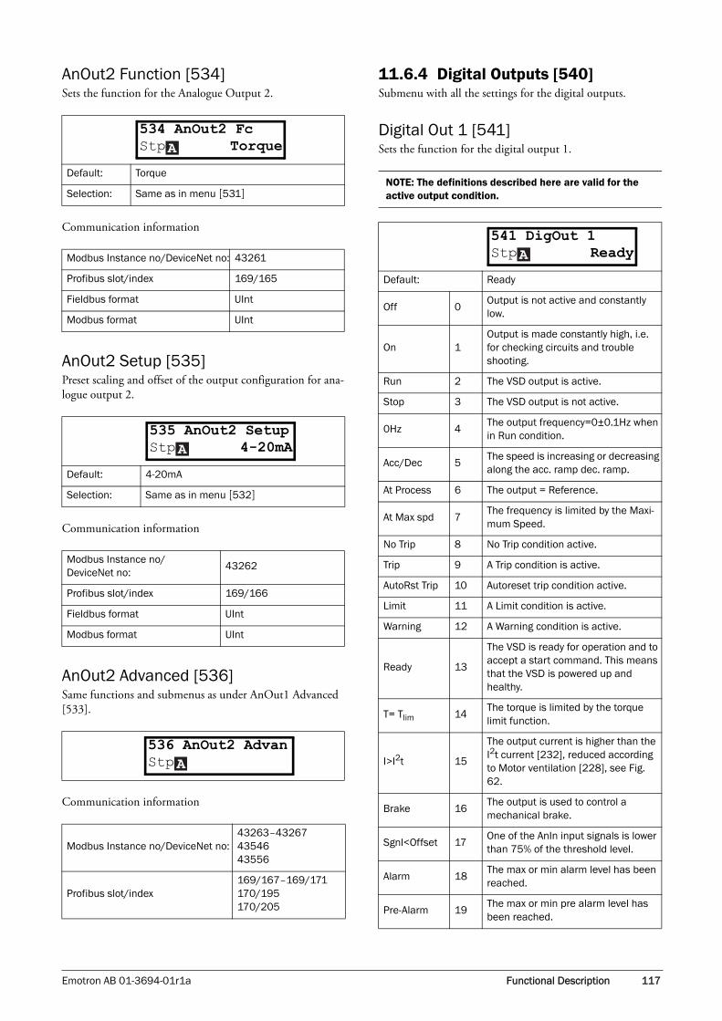
Emotron AB 01-3694-01r1a Functional Description 117
AnOut2 Function [534]Sets the function for the Analogue Output 2.
Communication information
AnOut2 Setup [535]Preset scaling and offset of the output configuration for ana-logue output 2.
Communication information
AnOut2 Advanced [536]Same functions and submenus as under AnOut1 Advanced [533].
Communication information
11.6.4 Digital Outputs [540]Submenu with all the settings for the digital outputs.
Digital Out 1 [541]Sets the function for the digital output 1.
Default: Torque
Selection: Same as in menu [531]
Modbus Instance no/DeviceNet no: 43261
Profibus slot/index 169/165
Fieldbus format UInt
Modbus format UInt
Default: 4-20mA
Selection: Same as in menu [532]
Modbus Instance no/DeviceNet no:
43262
Profibus slot/index 169/166
Fieldbus format UInt
Modbus format UInt
Modbus Instance no/DeviceNet no:43263–432674354643556
Profibus slot/index169/167–169/171170/195170/205
534 AnOut2 FcStp TorqueA
535 AnOut2 SetupStp 4-20mAA
536 AnOut2 AdvanStpA
NOTE: The definitions described here are valid for the active output condition.
Default: Ready
Off 0Output is not active and constantly low.
On 1Output is made constantly high, i.e. for checking circuits and trouble shooting.
Run 2 The VSD output is active.
Stop 3 The VSD output is not active.
0Hz 4The output frequency=0±0.1Hz when in Run condition.
Acc/Dec 5The speed is increasing or decreasing along the acc. ramp dec. ramp.
At Process 6 The output = Reference.
At Max spd 7The frequency is limited by the Maxi-mum Speed.
No Trip 8 No Trip condition active.
Trip 9 A Trip condition is active.
AutoRst Trip 10 Autoreset trip condition active.
Limit 11 A Limit condition is active.
Warning 12 A Warning condition is active.
Ready 13
The VSD is ready for operation and to accept a start command. This means that the VSD is powered up and healthy.
T= Tlim 14The torque is limited by the torque limit function.
I>I2t 15
The output current is higher than the I2t current [232], reduced according to Motor ventilation [228], see Fig. 62.
Brake 16The output is used to control a mechanical brake.
Sgnl<Offset 17One of the AnIn input signals is lower than 75% of the threshold level.
Alarm 18The max or min alarm level has been reached.
Pre-Alarm 19The max or min pre alarm level has been reached.
541 DigOut 1Stp ReadyA

118 Functional Description Emotron AB 01-3694-01r1a
Communication information
Digital Out 2 [542]
Sets the function for the digital output 2.
Communication information
Max Alarm 20The max alarm level has been reached.
Max PreAlarm 21The max pre alarm level has been reached.
Min Alarm 22The min alarm level has been reached.
Min PreAlarm 23The min pre alarm Level has been reached.
LY 24 Logic output Y.
!LY 25 Logic output Y inverted.
LZ 26 Logic output Z.
!LZ 27 Logic output Z inverted.
CA 1 28 Analogue comparator 1 output.
!A1 29 Analogue comp 1 inverted output.
CA 2 30 Analogue comparator 2 output.
!A2 31 Analogue comp 2 inverted output.
CD 1 32 Digital comparator 1 output.
!D1 33 Digital comp 1 inverted output.
CD 2 34 Digital comparator 2 output.
!D2 35 Digital comp 2 inverted output.
Operation 36 VSD in operation with motor
T1Q 37 Timer1 output
!T1Q 38 Timer1 inverted output
T2Q 39 Timer2 output
!T2Q 40 Timer2 inverted output
Sleeping 41 Activate the sleeping function
Crane Deviat 42 Tripped on deviation
PumpSlave1 43 Activate pump slave 1
PumpSlave2 44 Activate pump slave 2
PumpSlave3 45 Activate pump slave 3
PumpSlave4 46 Activate pump slave 4
PumpSlave5 47 Activate pump slave 5
PumpSlave6 48 Activate pump slave 6
PumpMaster1 49 Activate pump master 1
PumpMaster2 50 Activate pump master 2
PumpMaster3 51 Activate pump master 3
PumpMaster4 52 Activate pump master 4
PumpMaster5 53 Activate pump master 5
PumpMaster6 54 Activate pump master 6
All Pumps 55 All pumps are running
Only Master 56 Only the master is running
Loc/Rem 57 Local/Rem function is active
Standby 58 Standby supply option is active
PTC Trip 59 Trip when function is active
PT100 Trip 60 Trip when function is active
Overvolt 61 Overvoltage due to high main voltage
Overvolt G 62 Overvoltage due to generation mode
Overvolt D 63 Overvoltage due to deceleration
Acc 64 Acceleration
Dec 65 Deceleration
I2t 66 I2t limit protection active
V-Limit 67 Overvoltage limit function active
C-Limit 68 Overcurrent limit function active
Overtemp 69 Overtemperature warning
Low voltage 70 Low voltage warning
DigIn 1 71 Digital input 1
DigIn 2 72 Digital input 2
DigIn 3 73 Digital input 3
DigIn 4 74 Digital input 4
DigIn 5 75 Digital input 5
DigIn 6 76 Digital input 6
DigIn 7 77 Digital input 7
DigIn 8 78 Digital input 8
Modbus Instance no/DeviceNet no: 43271
Profibus slot/index 169/175
Fieldbus format UInt
Modbus format UInt
NOTE: The definitions described here are valid for the active output condition.
Default: No trip
Selection: Same as in menu [541]
Modbus Instance no/DeviceNet no: 43272
Profibus slot/index 169/176
Fieldbus format UInt
Modbus format UInt
542 DigOut2Stp No TripA

Emotron AB 01-3694-01r1a Functional Description 119
11.6.5 Relays [550]Submenu with all the settings for the relay outputs. The relay mode selection makes it possible to establish a “fail save” relay operation by using the normal closed contact to function as the normal open contact.
Relay 1 [551]Sets the function for the relay output 1. Same function as digital output 1 [541] can be selected.
Communication information
Relay 2 [552]
Sets the function for the relay output 2.
Communication information
Relay 3 [553]Sets the function for the relay output 3.
Communication information
Board Relay [554] to [55C]These additional relays are only visible if an I/O option board is fitted in slot 1, 2, or 3. The outputs are named B1 Relay 1–3, B2 Relay 1–3 and B3 Relay 1–3. B stands for board and 1–3 is the number of the board.
Communication information
Relay Advanced [55D]This function makes it possible to ensure that the relay will also be closed when the VSD is malfunctioning or powered down.
ExampleA process always requires a certain minimum flow. To con-trol the required number of pumps by the relay mode NC, the e.g. the pumps can be controlled normally by the pump control, but are also activated when the variable speed drive is tripped or powered down.
NOTE: Additional relays will become available when I/O option boards are connected. Maximum 3 boards with 3 relays each.
Default: Trip
Selection: Same as in menu [541]
Modbus Instance no/DeviceNet no: 43273
Profibus slot/index 169/177
Fieldbus format UInt
Modbus format UInt
NOTE: The definitions described here are valid for the active output condition.
Default: Run
Selection: Same as in menu [541]
Modbus Instance no/DeviceNet no: 43274
Profibus slot/index 169/178
Fieldbus format UInt
Modbus format UInt
551 Relay 1 Stp TripA
552 Relay 2 Stp RunA
Default: Off
Selection: Same as in menu [541]
Modbus Instance no/DeviceNet no: 43275
Profibus slot/index 169/179
Fieldbus format UInt
Modbus format UInt
Modbus Instance no/DeviceNet no: 43511–43519
Profibus slot/index 170/160–170/168
Fieldbus format UInt
Modbus format UInt
553 Relay 3 Stp OffA
55D Relay AdvStpA

120 Functional Description Emotron AB 01-3694-01r1a
Relay 1 Mode [55D1]
Communication information
Relay Modes [55D2] to [55DC]Same function as for relay 1 mode [55D1].
Communication information
11.6.6 Virtual Connections [560]Functions to enable eight internal connections of compara-tor, timer and digital signals, without occupying physical digital in/outputs. Virtual connections are used to wirelessly connect a digital output function to a digital input. Availa-ble signals and control functions can be used to create your own specific functions.
Example of start delayThe motor will start in RunR when DigIn1 gets high. DigIn1 has a time delay of 10 s.
Virtual Connection 1 Destination [561]With this function the destination of the virtual connection is established. When a function can be controlled by several sources, e.g. VC destination or Digital Input, the function will be controlled in conformity with “OR logic”. See DigIn for descriptions of the different selections.
Communication information
Default: N.O
N.O 0The normal open contact of the relay will be activated when the function is active.
N.C 1
The normally closed contact of the relay will act as a normal open con-tact. The contact will be opened when function is not active and closed when function is active.
Modbus Instance no/DeviceNet no: 43276
Profibus slot/index 169/180
Fieldbus format UInt
Modbus format UInt
Modbus Instance no/DeviceNet no:43277–43278, 43521–43529
Profibus slot/index169/181–169/182, 170/170–170/178
Fieldbus format UInt
Modbus format UInt
55D1 Relay ModeStp N.OA
Menu Parameter Setting
[521] DigIn1 Timer 1
[561] VIO 1 Dest RunR
[562] VIO 1 Source TQ1
[641] Timer1 Trig Off
[642] Timer1 Mode Delay
[643] Timer1 Delay 0:00:10
NOTE: When a digital input and a virtual destination are set to the same function, this function will act as an OR logic function.
Default: Off
Selection:Same selections as for Digital Input 1, menu [521].
Modbus Instance no/DeviceNet no: 43281
Profibus slot/index 169/185
Fieldbus format UInt
Modbus format UInt
561 VIO 1 DestStp OffA

Emotron AB 01-3694-01r1a Functional Description 121
Virtual Connection 1 Source [562]With this function the source of the virtual connection is defined. See DigOut 1 for description of the different selec-tions.
Communication information
Virtual Connections 2-8 [563] to [56G] Same function as virtual connection 1 [561] and [562].
Communication information for virtual connections 2-8 Destination.
Communication information for virtual connections 2-8 Source.
11.7 Logical Functions and Timers [600]
With the Comparators, Logic Functions and Timers, condi-tional signals can be programmed for control or signalling features. This gives you the ability to compare different sig-nals and values in order to generate monitoring/controlling features.
11.7.1 Comparators [610]The comparators available make it possible to monitor dif-ferent internal signals and values, and visualize via digital output or a contact, when a specific value or status is reached or established.
There are 2 analogue comparators that compare any availa-ble analogue value (including the analogue reference inputs) with two adjustable constants.
For the two analogue comparators two different constants are available, Level HI and Level LO. With these two levels, it is possible to create a clear hysteresis for the analogue com-parator between setting and resetting the comparator out-put. This function gives a clear difference in switching levels, which lets the process adapt until a certain action is started. With such a hysteresis, even an instable analogue signal can be monitored without getting a nervous comparator signal. Another function is to get a clear indication that a certain situation has occurred; the comparator can latch by set Level LO to a higher value than Level HI.
There are 2 digital comparators that compare any available digital signal.
The output signals of these comparators can be logically tied together to yield a logical output signal.
All the output signals can be programmed to the digital or relay outputs or used as a source for the virtual connections [560].
Analogue Comparator 1 Value [611]Selection of the analogue value for Analogue Comparator 1 (CA1).
Analogue comparator 1 compares the selectable analogue value in menu [611] with the constant Level HI in menu [612] and constant Level LO in menu [613]. When the value exceeds the constant level high, the output signal CA1 becomes high and !A1 low, see Fig. 95.
The output signal can be programmed as a virtual connec-tion source and to the digital or relay outputs.
Default: Off
Selection: Same as for menu [541].
Modbus Instance no/DeviceNet no: 43282
Profibus slot/index 169/186
Fieldbus format UInt
Modbus format UInt
Modbus Instance no/DeviceNet no:43283, 43285, 43287, 43289, 43291, 43293, 43295
Profibus slot/index169/ 187, 189, 191, 193, 195, 197, 199
Fieldbus format UInt
Modbus format UInt
Modbus Instance no/DeviceNet no:43284, 43286, 43288, 43290, 43292, 43294, 43296
Profibus slot/index169/ 188, 190, 192, 194, 196, 198, 200
Fieldbus format UInt
Modbus format UInt
562 VIO 1 SourceStp OffA
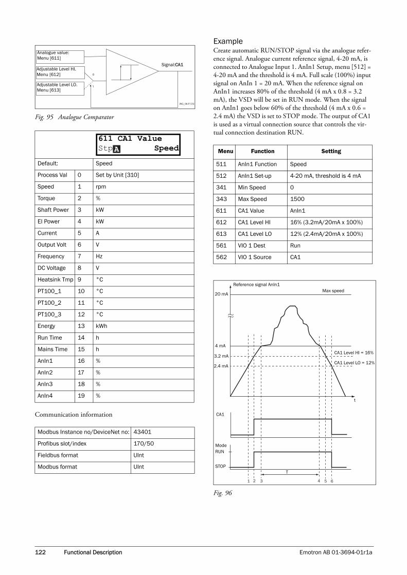
122 Functional Description Emotron AB 01-3694-01r1a
Fig. 95 Analogue Comparator
Communication information
ExampleCreate automatic RUN/STOP signal via the analogue refer-ence signal. Analogue current reference signal, 4-20 mA, is connected to Analogue Input 1. AnIn1 Setup, menu [512] = 4-20 mA and the threshold is 4 mA. Full scale (100%) input signal on AnIn 1 = 20 mA. When the reference signal on AnIn1 increases 80% of the threshold (4 mA x 0.8 = 3.2 mA), the VSD will be set in RUN mode. When the signal on AnIn1 goes below 60% of the threshold (4 mA x 0.6 = 2.4 mA) the VSD is set to STOP mode. The output of CA1 is used as a virtual connection source that controls the vir-tual connection destination RUN.
Fig. 96
Default: Speed
Process Val 0 Set by Unit [310]
Speed 1 rpm
Torque 2 %
Shaft Power 3 kW
El Power 4 kW
Current 5 A
Output Volt 6 V
Frequency 7 Hz
DC Voltage 8 V
Heatsink Tmp 9 °C
PT100_1 10 °C
PT100_2 11 °C
PT100_3 12 °C
Energy 13 kWh
Run Time 14 h
Mains Time 15 h
AnIn1 16 %
AnIn2 17 %
AnIn3 18 %
AnIn4 19 %
Modbus Instance no/DeviceNet no: 43401
Profibus slot/index 170/50
Fieldbus format UInt
Modbus format UInt
(NG_06-F125)
0
1
Signal:CA1
Analogue value:Menu [611]
Adjustable Level HI. Menu [612]
Adjustable Level LO. Menu [613]
611 CA1 ValueStp SpeedA Menu Function Setting
511 AnIn1 Function Speed
512 AnIn1 Set-up 4-20 mA, threshold is 4 mA
341 Min Speed 0
343 Max Speed 1500
611 CA1 Value AnIn1
612 CA1 Level HI 16% (3.2mA/20mA x 100%)
613 CA1 Level LO 12% (2.4mA/20mA x 100%)
561 VIO 1 Dest Run
562 VIO 1 Source CA1
1 2 3 4 5 6
20 mA
4 mA
3.2 mA
2.4 mA
CA1 Level HI = 16%
CA1 Level LO = 12%
Max speedReference signal AnIn1
CA1
ModeRUN
STOPT
t

Emotron AB 01-3694-01r1a Functional Description 123
Analogue Comparator 1 Level High [612]Selects the analogue comparator constant high level accord-ing to the selected value in menu [611].
The default value is always 300.
Communication information
ExampleThis example describes the normal use of the constant level high and low.
Fig. 97
No. Description
1The reference signal passes the Level LO value from below (positive edge), the comparator CA1 output stays low, mode=RUN.
2The reference signal passes the Level HI value from below (positive edge), the comparator CA1 output is set high, mode=RUN.
3The reference signal passes the threshold level of 4 mA, the motor speed will now follow the reference signal.
TDuring this period the motor speed will follow the refer-ence signal.
4The reference signal reaches the threshold level, motor speed is 0 rpm, mode = RUN.
5The reference signal passes the Level HI value from above (negative edge), the comparator CA1 output stays high, mode =RUN.
6The reference signal passes the Level LO value from above (negative edge), the comparator CA1 out-put=STOP.
Default: 300 rpm
Range: Enter a value for the high level.
Mode Min Max Decimals
Process 0 3
Speed, rpm 0 Max speed 0
Torque, % 0 Max torque 0
Shaft Power, kW 0 Motor Pnx4 0
El Power, kW 0 Motor Pnx4 0
Current, A 0 Motor Inx4 1
Output volt, V 0 1000 1
Frequency, Hz 0 400 1
DC voltage, V 0 1250 1
Heatsink temp, °C 0 100 1
PT 100_1_2_3, °C -100 300 1
Energy, kWh 0 1000000 0
Run time, h 0 65535 0
Mains time, h 0 65535 0
AnIn 1-4% 0 100 0
612 CA1 Level HIStp 300rpmA
Modbus Instance no/DeviceNet no: 43402
Profibus slot/index 170/51
Fieldbus format
Long,1=1 W, 0.1 A, 0.1 V, 0.1 Hz, 0.1°C, 1 kWh, 1H, 1%, 1 rpm or 0.001 via process value
Modbus format EInt
Menu Function Setting
343 Max Speed 1500
611 CA1 Value Speed
612 CA1 Level HI 300 rpm
613 CA1 Level LO 200 rpm
561 VC1 Dest RUN
562 VC1 Source CA1
1 2 3 4 5 6 7 8
t
MAX speed[343]
300
200
CA1 Level HI [612]
CA1 Level LO [613]
Hysteresis
OutputCA1High
Low

124 Functional Description Emotron AB 01-3694-01r1a
Analogue Comparator 1 Level Low [613]Selects the analogue comparator constant low level accord-ing to the selected value in menu [611].
The default value is always 0.
Communication information
Analogue Comparator 2 Value [614]Function is identical to analogue comparator 1 value.
Communication information
Analogue Comparator 2 Level High [615]Function is identical to analogue comparator 1 level high.
Communication information
Analogue Comparator 2 Level Low [616]Function is identical to analogue comparator 1 level low.
No. Description
1The reference signal passes the Level LO value from below (positive edge), the comparator CA1 does not change, output stays low.
2The reference signal passes the Level HI value from below (positive edge), the comparator CA1 output is set high.
3The reference signal passes the Level HI value from above (negative edge), the comparator CA1 does not change, output stays high.
4The reference signal passes the Level LO value from above (negative edge), the comparator CA1 is reset, output is set low.
5The reference signal passes the Level LO value from below (positive edge), the comparator CA1 does not change, output stays low.
6The reference signal passes the Level HI value from below (positive edge), the comparator CA1 output is set high.
7The reference signal passes the Level HI value from above (negative edge), the comparator CA1 does not change, output stays high.
8The reference signal passes the Level LO value from above (negative edge), the comparator CA1 is reset, output is set low.
Default: 200 rpm
Range: Enter a value for the low level.
Modbus Instance no/DeviceNet no: 43403
Profibus slot/index 170/52
Fieldbus format
Long, 1=1 W, 0.1 A, 0.1 V, 0.1 Hz, 0.1°C, 1 kWh, 1H, 1%, 1 rpm or 0.001 via process value
Modbus format EInt
613 CA1 Level LOStp 200rpmA
Default: Torque
Selections: Same as in menu [611]
Modbus Instance no/DeviceNet no: 43404
Profibus slot/index 170/53
Fieldbus format UInt
Modbus format UInt
Default: 20%
Range: Enter a value for the high level.
Modbus Instance no/DeviceNet no: 43405
Profibus slot/index 170/54
Fieldbus format
Long1=1 W, 0.1 A, 0.1 V, 0.1 Hz, 0.1°C, 1 kWh, 1H, 1%, 1 rpm or 0.001 via process value
Modbus format EInt
Default: 10%
Range: Enter a value for the low level.
614 CA2 ValueStp TorqueA
615 CA2 Level HIStp 20%A
616 CA2 Level LOStp 10%A

Emotron AB 01-3694-01r1a Functional Description 125
Communication information
Digital Comparator 1 [617]Selection of the input signal for digital comparator 1 (CD1).
The output signal CD1 becomes high if the selected input signal is active. See Fig. 98.
The output signal can be programmed to the digital or relay outputs or used as a source for the virtual connections [560].
Fig. 98 Digital comparator
Communication information
Digital Comparator 2 [618]Function is identical to digital comparator 1.
Communication information
11.7.2 Logic Output Y [620]By means of an expression editor, the comparator signals can be logically combined into the Logic Y function.
The expression editor has the following features:
• The following signals can be used: CA1, CA2, CD1, CD2 or LZ (or LY)
• The following signals can be inverted:!A1, !A2, !D1, !D2, or !LZ (or !LY)
• The following logical operators are available:"+" : OR operator"&" : AND operator "^" : EXOR operator
Expressions according to the following truth table can be made:
The output signal can be programmed to the digital or relay outputs or used as a Virtual Connection Source [560].
Communication information
The expression must be programmed by means of the menus [621] to [625].
Modbus Instance no/DeviceNet no: 43406
Profibus slot/index 170/55
Fieldbus format
Long,1=1 W, 0.1 A, 0.1 V, 0.1 Hz, 0.1°C, 1 kWh, 1H, 1%, 1 rpm or 0.001 via process value
Modbus format EInt
Default: Run
Selection: Same selections as for DigOut 1 [541].
Modbus Instance no/DeviceNet no: 43407
Profibus slot/index 170/56
Fieldbus format UInt
Modbus format UInt
Default: DigIn 1
Selection: Same selections as for DigOut 1 [541].
+
-
(NG_06-F126)
Signal: CD1Digital signal:Menu [617]
DComp 1
617 CD1Stp RunA
618 CD 2 Stp DigIn 1A
Modbus Instance no/DeviceNet no: 43408
Profibus slot/index 170/57
Fieldbus format UInt
Modbus format UInt
Input Result
A B & (AND) + (OR) ^(EXOR)
0 0 0 0 0
0 1 0 1 1
1 0 0 1 1
1 1 1 1 0
Modbus Instance no/DeviceNet no: 31035
Profibus slot/index 121/179
Fieldbus format Long
Modbus format Text
620 LOGIC YStp CA1&!A2&CD1

126 Functional Description Emotron AB 01-3694-01r1a
Example:
Broken belt detection for Logic YThis example describes the programming for a so-called “broken belt detection” for fan applications.
The comparator CA1 is set for frequency>10Hz.
The comparator !A2 is set for load < 20%.
The comparator CD1 is set for Run active.
The 3 comparators are all AND-ed, given the “broken belt detection”.
In menus [621]-[625] expression entered for Logic Y is visi-ble.
Set menu [621] to CA1Set menu [622] to &Set menu [623] to !A2Set menu [624] to &Set menu [625] to CD1
Menu [620] now holds the expression for Logic Y:
CA1&!A2&CD1
which is to be read as:
(CA1&!A2)&CD1
Y Comp 1 [621]Selects the first comparator for the logic Y function.
Communication information
Y Operator 1 [622]Selects the first operator for the logic Y function.
Communication information
Y Comp 2 [623]Selects the second comparator for the logic Y function.
Communication information
NOTE: Set menu [624] to "." to finish the expression when only two comparators are required for Logic Y.
Default: CA1
CA1 0
!A1 1
CA2 2
!A2 3
CD1 4
!D1 5
CD2 6
!D2 7
LZ/LY 8
!LZ/!LY 9
T1 10
!T1 11
T2 12
!T2 13
621 Y Comp 1Stp CA1A
Modbus Instance no/DeviceNet no: 43411
Profibus slot/index 170/60
Fieldbus format UInt
Modbus format UInt
Default: &
. 0When · (dot) is selected, the Logic Y expression is finished (when only two expressions are tied together).
& 1 &=AND
+ 2 +=OR
^ 3 ^=EXOR
Modbus Instance no/DeviceNet no: 43412
Profibus slot/index 170/61
Fieldbus format UInt
Modbus format UInt
Default: !A2
Selection: Same as menu [621]
Modbus Instance no/DeviceNet no: 43413
Profibus slot/index 170/62
Fieldbus format UInt
Modbus format UInt
622 Y Operator 1Stp &A
623 Y Comp 2Stp !A2A

Emotron AB 01-3694-01r1a Functional Description 127
Y Operator 2 [624]Selects the second operator for the logic Y function.
Communication information
Y Comp 3 [625]Selects the third comparator for the logic Y function.
Communication information
11.7.3 Logic Output Z [630]
The expression must be programmed by means of the menus [631] to [635].
Z Comp 1 [631]Selects the first comparator for the logic Z function.
Communication information
Z Operator 1 [632]Selects the first operator for the logic Z function.
Communication information
Z Comp 2 [633]Selects the second comparator for the logic Z function.
Communication information
Z Operator 2 [634]Selects the second operator for the logic Z function.
Default: &
Selection: Same as menu [622]
Modbus Instance no/DeviceNet no: 43414
Profibus slot/index 170/63
Fieldbus format UInt
Modbus format UInt
Default: CD1
Selection: Same as menu [621]
Modbus Instance no/DeviceNet no: 43415
Profibus slot/index 170/64
Fieldbus format UInt
Modbus format UInt
Default: CA1
Selection: Same as menu [621]
624 Y Operator 2Stp &A
625 Y Comp 3Stp CD1A
630 LOGIC ZStp CA1&!A2&CD1
631 Z Comp 1Stp CA1A
Modbus Instance no/DeviceNet no: 43421
Profibus slot/index 170/70
Fieldbus format UInt
Modbus format UInt
Default: &
Selection: Same as menu [622]
Modbus Instance no/DeviceNet no: 43422
Profibus slot/index 170/71
Fieldbus format UInt
Modbus format UInt
Default: !A1
Selection: Same as menu [621]
Modbus Instance no/DeviceNet no: 43423
Profibus slot/index 170/72
Fieldbus format UInt
Modbus format UInt
Default: &
Selection: Same as menu [622]
632 Z Operator 1Stp &A
633 Z Comp 2Stp !A1A
634 Z Operator 2Stp &A

128 Functional Description Emotron AB 01-3694-01r1a
Communication information
Z Comp 3 [635]Selects the third comparator for the logic Z function.
Communication information
11.7.4 Timer1 [640]The Timer functions can be used as a delay timer or as an interval with separate On and Off times (alternate mode). In delay mode, the output signal T1Q becomes high if the set delay time is expired. See Fig. 99.
Fig. 99
In alternate mode, the output signal T1Q will switch auto-matically from high to low etc. according to the set interval times. See Fig. 100.
The output signal can be programmed to the digital or relay outputs used in logic functions [620] and [630], or as a vir-tual connection source [560].
Fig. 100
Timer 1 Trig [641]
Communication information
Timer 1 Mode [642]
Communication information
Modbus Instance no/DeviceNet no: 43424
Profibus slot/index 170/73
Fieldbus format UInt
Modbus format UInt
Default: CD1
Selection: Same as menu [621]
Modbus Instance no/DeviceNet no: 43425
Profibus slot/index 170/74
Fieldbus format UInt
Modbus format UInt
635 Z Comp 3Stp CD1A
Timer1 Trig
or
DigInX=Timer1T1Q
Timer1 delay
Default: Off
Selection:Same selections as Digital Output 1 menu [541].
Modbus Instance no/DeviceNet no: 43431
Profibus slot/index 170/80
Fieldbus format UInt
Modbus format UInt
Default: Off
Off 0
Delay 1
Alternate 2
Modbus Instance no/DeviceNet no: 43432
Profibus slot/index 170/81
Fieldbus format UInt
Modbus format UInt
T1 T2 T1 T2
Timer1 Trig
or
DitIInX=Timer1
641 Timer1 TrigStp OffA
642 Timer1 ModeStp OffA

Emotron AB 01-3694-01r1a Functional Description 129
Timer 1 Delay [643]This menu is only visible when timer mode is set to delay.
Timer 1 delay sets the time that will be used by the first timer after it is activated. Timer 1 can be activated by a high signal on a DigIn that is set to Timer 1 or via a virtual desti-nation [560].
Communication information
Timer 1 T1 [644]When timer mode is set to Alternate and Timer 1 is enabled, this timer will automatically keep on switching according to the independently programmable up and down times. The Timer 1 in Alternate mode can be enabled by a digital input or via a virtual connection. See Fig. 99. Timer 1 T1 sets the up time in the alternate mode.
Communication information
Timer 1 T2 [645]Timer 1 T2 sets the down time in the alternate mode.
Communication information
11.7.5 Timer2 [650]Refer to the descriptions for Timer1.
Timer 2 Trig [651]
Communication information
Timer 2 Mode [652]
Default: 0:00:00 (hr:min:sec)
Range: 0:00:01–9:59:59
Modbus Instance no/DeviceNet no:43433 hours43434 minutes43435 seconds
Profibus slot/index170/82, 170/83,170/84
Fieldbus format UInt
Modbus format UInt
Default: 0:00:00 (hr:min:sec)
Range: 0:00:01–9:59:59
Modbus Instance no/DeviceNet no:43436 hours43437 minutes43438 seconds
Profibus slot/index170/85, 170/86,170/87
Fieldbus format UInt
Modbus format UInt
643 Timer1DelayStp 0:00:00A
644 Timer 1 T1Stp 0:00:00A
Default: 0:00:00, hr:min:sec
Range: 9hr_59min_59sec
Modbus Instance no/DeviceNet no:43439 hours43440 minutes43441 seconds
Profibus slot/index170/88, 170/89,170/90
Fieldbus format UInt
Modbus format UInt
NOTE: Timer 1 T1 [644] and Timer 2 T1 [654] are only visible when Timer Mode is set to Alternate.
Default: Off
Selection:Same selections as Digital Output 1 menu [541].
Modbus Instance no/DeviceNet no: 43451
Profibus slot/index 170/100
Fieldbus format UInt
Modbus format UInt
Default: Off
Selection: Same as in menu [642]
645 Timer1 T2Stp 0:00:00A
651 Timer2 TrigStp OffA
652 Timer2 ModeStp OffA

130 Functional Description Emotron AB 01-3694-01r1a
Communication information
Timer 2 Delay [653]
Communication information
Timer 2 T1 [654]
Communication information
Timer 2 T2 [655]
Communication information
11.8 View Operation/Status [700]
Menu with parameters for viewing all actual operational data, such as speed, torque, power, etc.
11.8.1 Operation [710]
Process Value [711]The process value is a display function which can be pro-grammed according to several quantities and units related to the speed.
Communication information
Speed [712]Displays the actual shaft speed.
Modbus Instance no/DeviceNet no: 43452
Profibus slot/index 170/101
Fieldbus format UInt
Modbus format UInt
Default: 0:00:00, hr:min:sec
Range: 9hr_59min_59sec
Modbus Instance no/DeviceNet no:43453 hours43454 minutes43455 seconds
Profibus slot/index170/102, 170/103,170/104
Fieldbus format UInt
Modbus format UInt
Default: 0:00:00, hr:min:sec
Range: 9hr_59min_59sec
Modbus Instance no/DeviceNet no:43456 hours43457 minutes43458 seconds
Profibus slot/index170/105, 170/106,170/107
Fieldbus format UInt
Modbus format UInt
653 Timer2DelayStp 0:00:00A
654 Timer 2 T1Stp 0:00:00A
Default: 0:00:00, hr:min:sec
Range: 9hr_59min_59sec
Modbus Instance no/DeviceNet no:43459 hours43460 minutes43461 seconds
Profibus slot/index170/108, 170/109,170/110
Fieldbus format UInt
Modbus format UInt
Modbus Instance no/DeviceNet no: 31001
Profibus slot/index 121/145
Fieldbus format Long, 1=0.001
Modbus format EInt
Unit: rpm
Resolution: 1 rpm, 4 digits
655 Timer 2 T2Stp 0:00:00A
711 Process ValStp
712 SpeedStp rpm

Emotron AB 01-3694-01r1a Functional Description 131
Communication information
Torque [713]Displays the actual shaft torque.
Communication information
Shaft power [714]Displays the actual shaft power.
Communication information
Electrical Power [715]Displays the actual electrical output power.
Communication information
Current [716]Displays the actual output current.
Communication information
Output Voltage [717]Displays the actual output voltage.
Communication information
Frequency [718]Displays the actual output frequency.
Modbus Instance no/DeviceNet no: 31002
Profibus slot/index 121/146
Fieldbus format Int, 1=1 rpm
Modbus format Int, 1=1 rpm
Unit: Nm
Resolution: 1 Nm
Modbus Instance no/DeviceNet no:31003 Nm31004%
Profibus slot/index 121/147
Fieldbus format Long, 1=1%
Modbus format EInt
Unit: W
Resolution: 1W
Modbus Instance no/DeviceNet no: 31005
Profibus slot/index 121/149
Fieldbus format Long, 1=1W
Modbus format EInt
Unit: kW
Resolution: 1 W
713 TorqueStp 0% 0.0Nm
714 Shaft PowerStp W
715 El PowerStp kW
Modbus Instance no/DeviceNet no: 31006
Profibus slot/index 121/150
Fieldbus format Long, 1=1W
Modbus format EInt
Unit: A
Resolution: 0.1 A
Modbus Instance no/DeviceNet no: 31007
Profibus slot/index 121/151
Fieldbus format Long, 1=0.1 A
Modbus format EInt
Unit: V
Resolution: 1 V
Modbus Instance no/DeviceNet no: 31008
Profibus slot/index 121/152
Fieldbus format Long, 1=0.1 V
Modbus format EInt
Unit: Hz
Resolution: 0.1 Hz
716 CurrentStp A
717 Output VoltStp V
718 FrequencyStp Hz

132 Functional Description Emotron AB 01-3694-01r1a
Communication information
DC Link Voltage [719]Displays the actual DC link voltage.
Communication information
Heatsink Temperature [71A]Displays the actual heatsink temperature.
Communication information
PT100_1_2_3 Temp [71B]Displays the actual PT100 temperature.
Communication information
11.8.2 Status [720]
VSD Status [721]Indicates the overall status of the variable speed drive.
Fig. 101 VSD status
Example: “A/Key/Rem/TL”This means:A: Parameter Set A is active.
Key: Reference value comes from the keyboard (CP).
Rem: Run/Stop commands come from terminals 1-22.
TL: Torque Limit active.
Modbus Instance no/DeviceNet no: 31009
Profibus slot/index 121/153
Fieldbus format Long, 1=0.1 Hz
Modbus format EInt
Unit: V
Resolution: 1 V
Modbus Instance no/DeviceNet no: 31010
Profibus slot/index 121/154
Fieldbus format Long, 1=0.1 V
Modbus format EInt
Unit: °C
Resolution: 0.1°C
Modbus Instance no/DeviceNet no: 31011
Profibus slot/index 121/155
Fieldbus format Long, 1=0.1°C
Modbus format EInt
Unit: °C
Resolution: 1°C
719 DC VoltageStp V
71A Heatsink TmpStp °C
71B PT100 1,2,3Stp °C
Modbus Instance no/DeviceNet no: 31012, 31013, 31014
Profibus slot/index 121/156
Fieldbus format Long
Modbus format EInt
Display position
Status Value
1 Parameter Set A,B,C,D
222Source of reference value
-Key (keyboard)-Rem (remote) -Comm (Serial comm.)-Opt (option)
333Source of Run/Stop/Reset com-mand
-Key (keyboard)-Rem (remote)-Comm (Serial comm.)-Opt (option)
44 Limit functions
-TL (Torque Limit)-FL (Frequency Limit)-CL (Current Limit)-VL (Voltage Limit)- - - -No limit active
721 VSD StatusStp 1/222/333/44

Emotron AB 01-3694-01r1a Functional Description 133
Warning [722]Display the actual or last warning condition. A warning occurs if the VSD is close to a trip condition but still in operation. During a warning condition the red trip LED will start to blink as long as the warning is active.
The active warning message is displayed in menu [722].
If no warning is active the message “No Warning” is dis-played.
The following warnings are possible:
Communication information
See also the Chapter 12. page 141.
Digital Input Status [723]Indicates the status of the Digital inputs. See Fig. 102.
The first row indicates the digital inputs.
1 DigIn 12 DigIn 23 DigIn 34 DigIn 45 DigIn 56 DigIn 67 DigIn 78 DigIn 8
Reading downwards from the first row to the second row the status of the associated input is shown:
1 High
0 Low
The example in Fig. 102 indicates that DigIn 1, DigIn 3 and DigIn 6 are active at this moment.
Fig. 102 Digital input status example
Communication information
Modbus no: Warning message
0 No Error
1 Motor I²t
2 PTC
3 Motor lost
4 Locked rotor
5 Ext trip
6 Mon MaxAlarm
7 Mon MinAlarm
8 Comm error
9 PT100
10 Deviation
11 Pump
12 Error 13
13 Error 14
14 Error 15
15 Option
16 Over temp
17 Over curr F
18 Over volt D
19 Over volt G
20 Over volt M
21 Over speed
22 Under voltage
23 Power fault
24 Desat
25 DClink error
26 Int error
27 Ovolt m cut
28 Over voltage
722 WarningsStp warn.msg
29 Warning 30
30 Warning 31
31 Warning 32
Modbus Instance no/DeviceNet no: 31016
Profibus slot/index 121/160
Fieldbus format Long
Modbus format UInt
Modbus Instance no/DeviceNet no: 31017
Profibus slot/index 121/161
Fieldbus format UInt, bit 0=DigIn1, bit 8=DigIn8Modbus format
Modbus no: Warning message
723 DigIn StatusStp 1010 0100

134 Functional Description Emotron AB 01-3694-01r1a
Digital Output Status [724]Indicates the status of the digital outputs and relays. See Fig. 103. the first row indicates the digital outputs.
1 DigOut12 DigOut2
Reading downwards from the first row to the second row the status of the associated output is shown.
1 High0 Low
The example in Fig. 103 indicates that DigOut1 is active and Digital Out 2 is not active.
Fig. 103 Digital output status example
Communication information
Analogue Input Status [725]Indicates the status of the analogue inputs 1 and 2.
Fig. 104 Analogue input status
Communication information
The first row indicates the analogue inputs.
1 AnIn 12 AnIn 2
Reading downwards from the first row to the second row the status of the belonging input is shown in %:
-100% AnIn1 has a negative 100% input value65% AnIn2 has a 65% input value
So the example in Fig. 104 indicates that both the Analogue inputs are active.
Analogue Input Status [726]Indicates the status of the analogue inputs 3 and 4.
Fig. 105 Analogue input status
Communication information
Analogue Output Status [727]Indicates the status of the analogue outputs. Fig. 106.
Fig. 106 Analogue output status
Communication information
The first row indicates the Analogue outputs.
1 AnOut 12 AnOut 2
Reading downwards from the first row to the second row the status of the belonging input is shown in %:
-100% AnOut1 has a negative 100% input value65% AnOut1 has a 65% input value
The example in Fig. 106 indicates that both the Analogue outputs are active.
Modbus Instance no/DeviceNet no: 31018
Profibus slot/index 121/162
Fieldbus format UInt, bit 0=DigOut1,bit 1=DigOut2bit 8=Relay1bit 9=Relay2bit 10=Relay3
Modbus format
Modbus Instance no/DeviceNet no: 31019, 31020
Profibus slot/index 121/163, 121/164
Fieldbus format Long, 1=1%
Modbus format EInt
724 DigOutStatusStp RE000 DO 10
725 AnIn 1 2 Stp -100% 65%
Modbus Instance no/DeviceNet no: 31021, 31022
Profibus slot/index 121/165, 121/166
Fieldbus format Long, 1=1%
Modbus format EInt
Modbus Instance no/DeviceNet no: 31023, 31024
Profibus slot/index 121/167, 121/168
Fieldbus format Long, 1=1%
Modbus format EInt
726 AnIn 3 4Stp -100% 65%
727 AnOut 1 2Stp -100% 65%

Emotron AB 01-3694-01r1a Functional Description 135
I/O board Status [728] - [72A]Indicates the status for the additional I/O on option boards 1 (B1), 2 (B2) and 3 (B3).
Communication information
11.8.3 Stored values [730]The shown values are the actual values built up over time. Values are stored at power down and updated again at power up.
Run Time [731]Displays the total time that the VSD has been in the Run Mode.
Communication information
Reset Run Time [7311]Reset the run time counter. The stored information will be erased and a new registration period will start.
Communication information
Mains time [732]Displays the total time that the VSD has been connected to the mains supply. This timer cannot be reset.
Communication information
Modbus Instance no/DeviceNet no: 31025 - 31027
Profibus slot/index 121/170 - 172
Fieldbus format UInt, bit 0=DigIn1bit 1=DigIn2bit 2=DigIn3bit 8=Relay1bit 9=Relay2bit 10=Relay3
Modbus format
Unit: h: m: s (hours: minutes: seconds)
Range: 0h: 0m: 0s–65535h: 59m: 59s
Modbus Instance no/DeviceNet no:31028 hours31029 minutes31030 seconds
Profibus slot/index121/172121/173121/174
Fieldbus format UInt, 1=1h/m/s
Modbus format UInt, 1=1h/m/s
728 IO B1 Stp RE000 DI10
731 Run TimeStp h:m:s
Default: No
No 0
Yes 1
Modbus Instance no/DeviceNet no: 7
Profibus slot/index 0/6
Fieldbus format UInt
Modbus format UInt
NOTE: After reset the setting automatically reverts to “No”.
Unit: h: m: s (hours: minutes: seconds)
Range: 0h: 0m: 0s–65535h: 59m: 59s
Modbus Instance no/DeviceNet no:31031 hours31032 minutes31033 seconds
Profibus slot/index121/175121/176121/177
Fieldbus format UInt, 1=1h/m/s
Modbus format UInt, 1=1h/m/s
NOTE: At 65535 h: 59 m the counter stops. It will not revert to 0h: 0m.
7311 Reset RunTmStp No
732 Mains TimeStp h:m:s

136 Functional Description Emotron AB 01-3694-01r1a
Energy [733]Displays the total energy consumption since the last energy reset [7331] took place.
Communication information
Reset Energy [7331]Resets the kWh counter. The stored information will be erased and a new registration period will start.
Communication information
11.9 View Trip Log [800]Main menu with parameters for viewing all the logged trip data. In total the VSD saves the last 10 trips in the trip memory. The trip memory refreshes on the FIFO principle (First In, First Out). Every trip in the memory is logged on the time of the Run Time [731] counter. At every trip, the actual values of several parameter are stored and available for troubleshooting.
11.9.1 Trip Message log [810]Display the cause of the trip and what time the it occurred. When a trip occurs the status menus are copied to the trip message log. There are nine trip message logs [810]–[890]. When the tenth trip occurs the oldest trip will disappear.
Communication information
Unit: kWh
Range: 0.0–999999kWh
Modbus Instance no/DeviceNet no: 31034
Profibus slot/index 121/178
Fieldbus format Long, 1=1 W
Modbus format EInt
Default: No
Selection: No, Yes
Modbus Instance no/DeviceNet no: 6
Profibus slot/index 0/5
Fieldbus format UInt
Modbus format UInt
NOTE: After reset the setting automatically goes back to “No”.
733 EnergyStp kWh
7331 Rst EnergyStp No
Unit: h: m (hours: minutes)
Range: 0h: 0m–65355h: 59m
Modbus Instance no/DeviceNet no: 31101
Profibus slot/index 121/245
Fieldbus format UInt
Modbus format UInt
8x0 Trip messageStp h:mm:ss
810 Ext TripStp 132:12:14

Emotron AB 01-3694-01r1a Functional Description 137
Trip message [811]-[81N]The information from the status menus are copied to the trip message log when a trip occurs.
Communication information
Example: Fig. 107 shows the third trip memory menu [830]: Torque trip occurred after 1396 hours and 13 minutes in Run time.
Fig. 107 Trip 3
11.9.2 Trip Messages [820] - [890]Same information as for menu [810].
Communication information
All nine alarm lists contain the same type of data. For exam-ple DeviceNet parameter 31101 in alarm list 1 contains the same data information as 31151 in alarm list 2. It is possible to read all parameters in alarm lists 2–9 by recalculating the DeviceNet instance number into a Profibus slot/index number. This is done in the following way:
slot no = abs((dev instance no-1)/255)index no = (dev instance no-1) modulo 255dev instance no = slot nox255+index no+1
Example: We want to read out the process value out from alarm list 9. In alarm list 1 process value has the DeviceNet instance number 31102. In alarm list 9 it has DeviceNet instance no 31502 (see table 2 above). The corresponding slot/index no is then:
slot no = abs((31502-1)/255)=123index no (modulo)= the remainder of the division above = 136, calculated as: (31502-1)-123x255=136
Trip menu Copied from Description
811 711 Process Value
812 712 Speed
813 712 Torque
814 714 Shaft Power
815 715 Electrical Power
816 716 Current
817 717 Output voltage
818 718 Frequency
819 719 DC Link voltage
81A 71A Heatsink Temperature
81B 71B PT100_1, 2, 3
81C 721 VSD Status
81D 723 Digital input status
81E 724 Digital output status
81F 725 Analogue input status 1-2
81G 726 Analogue input status 3-4
81H 727 Analog output status 1-2
81I 728 I/O status option board 1
81J 729 I/O status option board 2
81K 72A I/O status option board 3
81L 731 Run Time
81M 732 Mains Time
81N 733 Energy
Modbus Instance no/DeviceNet no: 31102 - 31134
Profibus slot/index121/246 - 254,122/0 - 23
Fieldbus format UInt
Modbus format UInt
830 Over tempStp 1396h:13m
Modbus Instance no/DeviceNet no:
31151–3118431201–3123431251–3128431301–3133431351–3138431401–3143431451–3148431501–31534
Trip log list23456789
Profibus slot/index
122/40–122/73122/90–122/123122/140–122/173122/190–122/223122/240–123/18123/35 - 123/68123/85–123/118123/135–123/168
Trip log list23456789
Fieldbus format UInt
Modbus format UInt

138 Functional Description Emotron AB 01-3694-01r1a
11.9.3 Reset Trip Log [8A0]Resets the content of the 10 trip memories.
Communication information
11.10 System Data [900]Main menu for viewing all the VSD system data.
11.10.1 VSD Data [920]
VSD Type [921]Shows the VSD type according to the type number.
The other options are indicated on the type plate of the VSD.
Example of type
Communication information
Examples:FDU40-073 FDU-series suited for 400 volt mains supply, and a rated output current of 74 A.
Software [922]Shows the software version number of the VSD.
Fig. 108 gives an example of the version number.
Fig. 108 Example of software version
Communication information
V 1.23 = Version of the Software
Unit name [923]Option to enter a name of the unit for service use or cus-tomer identity. The function enables the user to define a name with 12 symbols. Use the Prev and Next key to move the cursor to the required position. Then use the + and - keys to scroll in the character list. Confirm the character by moving the cursor to the next position by pressing the Next key. See section User-defined Unit [323].
Default: No
No 0
Yes 1
Modbus Instance no/DeviceNet no: 8
Profibus slot/index 0/7
Fieldbus format UInt
Modbus format UInt
NOTE: After the reset the setting goes automatically back to “NO”. The message “OK” is displayed for 2 sec.
Modbus Instance no/DeviceNet no: 31037
Profibus slot/index 121/181
Fieldbus format Long
Modbus format Text
8A0 Reset TripStp No
921 VSD TypeStp FDU40-074
Modbus Instance no/DeviceNet no:31038 software version31039 option version
Profibus slot/index 121/182
Fieldbus format UInt
Modbus format UInt
Table 26 Information for Modbus and Profibus number
Bit Description
7–0 minor
8–13 major
14–15 release
0 V, release version
1 P, pre-release version
2 β, Beta version
3 α, Alpha version
NOTE: It is important that the software version displayed in menu [920] is the same software version number as the software version number written on the title page of this instruction manual. If not, the functionality as described in this manual may differ from the functionality of the VSD.
922 SoftwareStp V 1.23
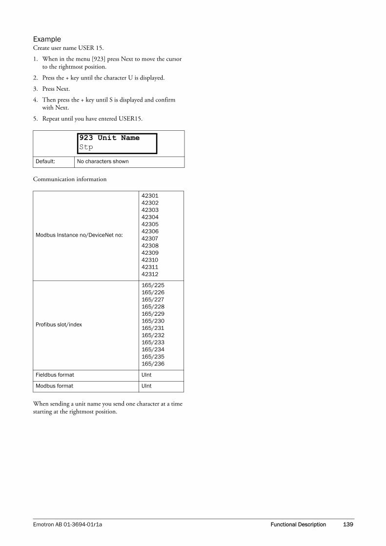
Emotron AB 01-3694-01r1a Functional Description 139
ExampleCreate user name USER 15.
1. When in the menu [923] press Next to move the cursor to the rightmost position.
2. Press the + key until the character U is displayed.
3. Press Next.
4. Then press the + key until S is displayed and confirm with Next.
5. Repeat until you have entered USER15.
Communication information
When sending a unit name you send one character at a time starting at the rightmost position.
Default: No characters shown
Modbus Instance no/DeviceNet no:
423014230242303423044230542306423074230842309423104231142312
Profibus slot/index
165/225165/226165/227165/228165/229165/230165/231165/232165/233165/234165/235165/236
Fieldbus format UInt
Modbus format UInt
923 Unit NameStp

140 Functional Description Emotron AB 01-3694-01r1a

Emotron AB 01-3694-01r1a Troubleshooting, Diagnoses and Maintenance 141
12. Troubleshooting, Diagnoses and Maintenance
12.1 Trips, warnings and limitsIn order to protect the variable speed drive the principal operating variables are continuously monitored by the sys-tem. If one of these variables exceeds the safety limit an error/warning message is displayed. In order to avoid any possibly dangerous situations, the inverter sets itself into a stop Mode called Trip and the cause of the trip is shown in the display.
Trips will always stop the VSD. Trips can be divided into normal and soft trips, depending on the setup Trip Type, see menu [250] Autoreset. Normal trips are default. For normal trips the VSD stops immediately, i.e. the motor coasts natu-rally to a standstill. For soft trips the VSD stops by ramping down the speed, i.e. the motor decelerates to a standstill.
“Normal Trip”• The VSD stops immediately, the motor coasts to natu-
rally to a standstill.
• The Trip relay or output is active (if selected).
• The Trip LED is on.
• The accompanying trip message is displayed.
• The “TRP” status indication is displayed (area C of the display).
“Soft Trip”• the VSD stops by decelerating to a standstill.
During the deceleration.
• The accompanying trip message is displayed, including an additional soft trip indicator “S” before the trip time.
• The Trip LED is blinking.
• The Warning relay or output is active (if selected).
After standstill is reached.
• The Trip LED is on.
• The Trip relay or output is active (if selected).
• The “TRP” status indication is displayed (area C of the display).
Apart from the TRIP indicators there are two more indica-tors to show that the inverter is in an “abnormal” situation.
“Warning”• The inverter is close to a trip limit.
• The Warning relay or output is active (if selected).
• The Trip LED is blinking.
• The accompanying warning message is displayed in win-dow [722] Warning.
• One of the warning indications is displayed (area C of the display).
“Limits”• The inverter is limiting torque and/or frequency to avoid
a trip.
• The Limit relay or output is active (if selected).
• The Trip LED is blinking.
• One of the Limit status indications is displayed (area C of the display).
Table 27 List of trips and warnings
Trip/Warningmessages
SelectionsTrip
(Normal/Soft)
Warning indicators (Area C)
Motor I2t Trip/Off/Limit Normal/Soft I2t
PTC Trip/Off Normal/Soft
Motor lost Trip/Off Normal
Locked rotor Trip/Off Normal
Ext trip Via DigIn Normal/Soft
Mon MaxAlarm Trip/Off/Warn Normal/Soft -
Mon MinAlarm Trip/Off/Warn Normal/Soft -
Comm error Trip/Off/Warn Normal/Soft -
PT100 Trip/Off Normal/Soft
Deviation Via Option Normal
Pump Via Option Normal
Over temp On Normal OT
Over curr F On Normal
Over volt D On Normal
Over volt G On Normal
Over volt M On Normal
Over speed On Normal
Under voltage On Normal LV
Power Fault On Normal -
Desat On Normal
DClink error On Normal
Ovolt m cut On Normal
Over voltage Warning VL
Safe stop Warning SST
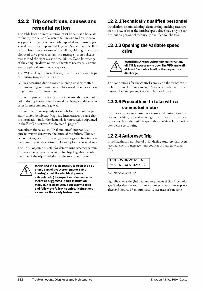
142 Troubleshooting, Diagnoses and Maintenance Emotron AB 01-3694-01r1a
12.2 Trip conditions, causes and remedial action
The table later on in this section must be seen as a basic aid to finding the cause of a system failure and to how to solve any problems that arise. A variable speed drive is mostly just a small part of a complete VSD system. Sometimes it is diffi-cult to determine the cause of the failure, although the varia-ble speed drive gives a certain trip message it is not always easy to find the right cause of the failure. Good knowledge of the complete drive system is therefore necessary. Contact your supplier if you have any questions.
The VSD is designed in such a way that it tries to avoid trips by limiting torque, overvolt etc.
Failures occurring during commissioning or shortly after commissioning are most likely to be caused by incorrect set-tings or even bad connections.
Failures or problems occurring after a reasonable period of failure-free operation can be caused by changes in the system or in its environment (e.g. wear).
Failures that occur regularly for no obvious reasons are gen-erally caused by Electro Magnetic Interference. Be sure that the installation fulfils the demands for installation stipulated in the EMC directives. See chapter 8. page 47.
Sometimes the so-called “Trial and error” method is a quicker way to determine the cause of the failure. This can be done at any level, from changing settings and functions to disconnecting single control cables or replacing entire drives.
The Trip Log can be useful for determining whether certain trips occur at certain moments. The Trip Log also records the time of the trip in relation to the run time counter.
12.2.1 Technically qualified personnelInstallation, commissioning, demounting, making measure-ments, etc., of or at the variable speed drive may only be car-ried out by personnel technically qualified for the task.
12.2.2 Opening the variable speed drive
The connections for the control signals and the switches are isolated from the mains voltage. Always take adequate pre-cautions before opening the variable speed drive.
12.2.3 Precautions to take with a connected motor
If work must be carried out on a connected motor or on the driven machine, the mains voltage must always first be dis-connected from the variable speed drive. Wait at least 5 min-utes before continuing.
12.2.4 Autoreset TripIf the maximum number of Trips during Autoreset has been reached, the trip message hour counter is marked with an “A”.
Fig. 109 Autoreset trip
Fig. 109 shows the 3rd trip memory menu [830]: Overvolt-age G trip after the maximum Autoreset attempts took place after 345 hours, 45 minutes and 12 seconds of run time.
WARNING: If it is necessary to open the VSD or any part of the system (motor cable housing, conduits, electrical panels, cabinets, etc.) to inspect or take measure-ments as suggested in this instruction manual, it is absolutely necessary to read and follow the following safety instructions as well as the safety instructions.
WARNING: Always switch the mains voltage off if it is necessary to open the VSD and wait at least 5 minutes to allow the capacitors to discharge.
830 OVERVOLT GTrp A 345:45:12

Emotron AB 01-3694-01r1a Troubleshooting, Diagnoses and Maintenance 143
Table 28 Trip condition, their possible causes and remidial action
Trip condition Possible Cause Remedy
Motor I2t“I2t”
I2t value is exceeded.- Overload on the motor according to the
programmed I2t settings.
- Check on mechanical overload on themotor or the machinery (bearings, gearboxes, chains, belts, etc.)
- Change the Motor I2t Current setting
PTC
Motor thermistor (PTC) exceeds maximum level.
NOTE: Only valid if option board PTX/Encoder is used.
- Check on mechanical overload on themotor or the machinery (bearings, gearboxes, chains, belts, etc.)
- Check the motor cooling system.- Self-cooled motor at low speed, too high
load.- Set PTC to OFF
Motor lostPhase loss or too great imbalance on the motor phases
- Check the motor voltage on all phases.- Check for loose or poor motor cable
connections- If all connections are OK, contact your
supplier- Set motor lost alarm to OFF.
Locked rotorTorque limit at motor standstill:- Mechanical blocking of the rotor.
- Check for mechanical problems at themotor or the machinery connected to themotor
- Set locked rotor alarm to OFF.
Ext tripExternal input (DigIn 1-8) active:- active low function on the input.
- Check the equipment that initiates theexternal input
- Check the programming of the digitalinputs DigIn 1-8
Mon MaxAlarmMax alarm level (overload) has been reached.
- Check the load condition of the machine- Check the monitor setting in section 11.7, page 121.
Mon MinAlarmMin alarm level (underload) has been reached.
- Check the load condition of the machine- Check the monitor setting in section 11.7, page 121.
Comm error Error on serial communication (option)
- Check cables and connection of theserial communication.
- Check all settings with regard to theserial communication
- Restart the equipment including theVSD
PT100
Motor PT100 elements exceeds maximum level.
NOTE: Only valid if option board PTX/Encoder is used.
- Check on mechanical overload on themotor or the machinery (bearings, gearboxes, chains, belts, etc.)
- Check the motor cooling system. - Self-cooled motor at low speed, too high
load.- Set PT100 to OFF
Deviation
CRIO board detecting deviation in motor operation.
NOTE: Only used in Crane Control.
- Check encoder signals- Check Deviation jumper on Crane option
board.
Pump
No master pump can be selected due to error in feedback signaling.
NOTE: Only used in Pump Control.
- Check cables and wiring for Pump feedback signals
- Check settings with regard to the pumpfeedback digital inputs

144 Troubleshooting, Diagnoses and Maintenance Emotron AB 01-3694-01r1a
Over temp
Heatsink temperature too high:- Too high ambient temperature of the
VSD- Insufficient cooling- Too high current- Blocked or stuffed fans
- Check the cooling of the VSD cabinet.- Check the functionality of the built-in
fans. The fans must switch on automa-tically if the heatsink temperature getstoo high. At power up the fans are brieflyswitched on.
- Check VSD and motor rating- Clean fans
Over curr F
Motor current exceeds the peak VSD current:- Too short acceleration time.- Too high motor load- Excessive load change- Soft short-circuit between phases or
phase to earth- Poor or loose motor cable connections- Too high IxR Compensation level
- Check the acceleration time settings andmake them longer if necessary.
- Check the motor load.- Check on bad motor cable connections- Check on bad earth cable connection- Check on water or moisture in the motor
housing and cable connections.- Lower the level of IxR Compensation
[352]
Over volt D(eceleration) Too high DC Link voltage:- Too short deceleration time with
respect to motor/machine inertia.- Too small brake resistor malfunctioning
Brake chopper
- Check the deceleration time settings andmake them longer if necessary.
- Check the dimensions of the brake resistor and the functionality of the Brakechopper (if used)
Over volt G(enerator)
Over volt (Mains)Too high DC Link voltage, due to too high mains voltage
- Check the main supply voltage- Try to take away the interference cause
or use other main supply lines.Over (Mains) cut
Over speedMotor speed measurement exceeds maxi-mum level.
Check encoder cables, wiring and setupCheck motor data setup [22x]Perform short ID-run
Under voltage
Too low DC Link voltage: - Too low or no supply voltage- Mains voltage dip due to starting other
major power consuming machines onthe same line.
- Make sure all three phases are properlyconnected and that the terminal screwsare tightened.
- Check that the mains supply voltage is within the limits of the VSD.
- Try to use other mains supply lines if dipis caused by other machinery
- Use the function low voltage override[421]
Power Fault Overload condition in the DC-link:- Hard short-circuit between phases or
phase to earth- Saturation of current measurement
circuiting- Earth fault- Desaturation of IGBTs- Peak voltage on DC link
- Check on bad motor cable connections - Check on bad earth cable connection - Check on water or moisture in the motor
housing and cable connections- Check that rating plate data of the motor
is correctly entered- See overvoltage trips
Desat
Power Fault Error on power board. - Check mains supply voltage
Fan Error Error in fan module - Check for clogged filters
HCB Error Error in controlled rectifier module (HCB) Check mains supply voltage
Table 28 Trip condition, their possible causes and remidial action

Emotron AB 01-3694-01r1a Troubleshooting, Diagnoses and Maintenance 145
12.3 MaintenanceThe variable speed drive is designed not to require any serv-icing or maintenance. There are however some things which must be checked regularly.
All variable speed drives have built-in fans which are auto-matically switched on if the heatsink temperature reaches 60°C. This means that the fans are only running if the VSD is running and loaded. The design of the heatsinks is such that the fan does not blow the cooling air through the inte-rior of the VSD, but only across the outer surface of the heatsink. However, running fans will always attract dust. Depending on the environment the fan and the heatsink will collect dust. Check this and clean the heatsink and the fans when necessary.
If variable speed drives are built into cabinets, also check and clean the dust filters of the cabinets regularly.
Check external wiring, connections and control signals. Tighten terminal screws if necessary.
Desat
Failure in output stage, desaturation of IGBTs
- Check on bad motor cable connections- Check on bad earth cable connections- Check on water and moisture in the
motor housing and cable connections
Desat U+
Desat U-
Desat V+
Desat V-
Desat W+
Desat W-
Desat BCC
DC link errorDC link voltage ripple exceeds maximum level
- Make sure all three phases are properlyconnected and that the terminal screwsare tightened.
- check that the mains supply voltage iswithin the limits of the VSD.
- Try to use other mains supply lines if dipis caused by other machinery.
Table 28 Trip condition, their possible causes and remidial action

146 Troubleshooting, Diagnoses and Maintenance Emotron AB 01-3694-01r1a

Emotron AB 01-3694-01r1a Options 147
13. Options
The standard options available are described here briefly. Some of the options have their own instruction or installa-tion manual. For more information please contact your sup-plier.
13.1 Protection class IP54All VSD models are available in protection class IP54, according to the EN 60529 standard.
The table below shows the versions with respect to the standard IP20 version.
13.2 Options for the control panel
Mounting cassette, blank panel and straight RS232-cable are available as options for the control panel. These options may be useful, for example after mounting a control panel in a cabinet door.
Fig. 110 Control panel in mounting cassette
Table 29 Options
Type 400V/500V IP20 IP54
FDU40-003FDU40-004FDU40-006FDU40-008FDU40-010FDU40-013
Standard unit Standard unit, same size as IP 20
40-013FDU**-018FDU**-026FDU**-031FDU**-037
Not available Standard unit
FDU**-046FDU**-060FDU-073
Standard unit Standard unit, same size as IP 20
FDU**-090FDU**-109FDU**-146FDU**-175
Standard unitStandard unit, same size as IP 20Standard unit, same size as IP 20
FDU**-210FDU**-250
Not available Standard unit

148 Options Emotron AB 01-3694-01r1a
13.3 EmoSoftComEmoSoftCom is an optional software that runs on a personal computer. EmoSoftCom is used to set parameters and simu-late the settings before transferring the parameters to the VSD. It can also be used to load parameter settings from the VSD to the PC for statistic calculations etc.
13.4 Brake chopperAll VSD sizes can be fitted with an optional built-in brake chopper. The brake resistor must be mounted outside the VSD. The choice of the resistor depends on the application switch-on duration and duty-cycle.
The following formula can be used to define the power of the connected brake resistor:
Where:
Presistor required maximum power of brake resistor
Brake level VDC DC brake voltage level (see Table 30and Table 31)
Rmin minimum allowable brake resistor (see Table 30 and Table 31+1
ED% effective braking period; to define by
WARNING: The table gives the minimum values of the brake resistors. Do not use resistors lower than this value. The VSD can trip or even be damaged due to high braking currents.
Table 30 Brake resistor 380–480V type
TypeMax.supply voltage AC
Brake level VDC
Minimum brake
resistance Rmin [ohm]
FDU40-003 415 680 227
-004 415 680 141.67
-006 415 680 94.44
-008 415 680 75.56
-010 415 680 59.65
-013 415 680 43.59
-018 415 680 31.48
-026 415 680 21.79
Presistor = (Brake level VDC)2
Rmin
x ED%
ED% = active brake time [s]
120 [s]and a maximum value of 1= continuous braking
-031 415 680 18.28
-037 415 680 15.32
-046 415 680 12.32
-060 415 680 9.29
-073 415 680 7.66
FDU48-090 480 800 7.41
-109 480 800 6.12
-146 480 800 4.57
-175 480 800 3.81
-210 480 800 3.17
-250 480 800 2.67
-300 480 800 2x 4.57
-375 480 800 2x 3.81
-430 480 800 2x 3.17
-500 480 800 2x 2.67
-600 480 800 3x 3.17
-650 480 800 3x 3.17
-750 480 800 3x 2.67
-860 480 800 4x 3.17
-1k0 480 800 4x 2.67
-1k2 480 800 6x 3.17
-1k5 480 800 6x 2.67
Table 31 Brake resistors 500–690 V types
TypeMax.supply voltage AC
Brake level VDC
Minimum brake
resistance Rmin [ohm]
FDU50-018 525 875 40.51
-026 525 875 28.04
-031 525 875 23.52
-037 525 875 19.71
-046 525 875 15.85
-060 525 875 11.95
-073 525 875 9.85
FDU69-090 690 1200 11.11
-109 690 1200 9.17
-146 690 1200 6.85
-175 690 1200 5.71
-210 690 1200 4.76
-250 690 1200 4.00
-300 690 1200 2x 6.85
-375 690 1200 2x 5.71
Table 30 Brake resistor 380–480V type

Emotron AB 01-3694-01r1a Options 149
The brake chopper option is built-in by the manufacturer and must be specified when the VSD is ordered.
13.5 I/O BoardThe I/O option board 2.0 gives three extra relay outputs. The I/O Board works in combination with the Pump/Fan Control, but can also be used as a separate option. This option is described in a separate manual.
13.6 Output coilsOutput coils, which are supplied separately, are recom-mended for lengths of screened motor cable longer than 40 m for FDU 40-003 to 013 and longer than 100 m for all other VSD models. Because of the fast switching of the motor voltage and the capacity of the motor cable both line to line and line to earth screen, large switching currents can be generated with long lengths of motor cable. Output coils prevent the VSD from tripping and should be installed as closely as possible to the VSD.
13.7 Serial communication and fieldbus
For communication with the VSD there are several option boards for communication. There is one board for Fieldbus communication, one for serial communication via RS232 or RS485 and one board for serial communication with gal-vanic isolation.
13.8 Standby supply optionThe standby supply option provides for the possibility of keeping the communication system up and running without having the 3-phase mains connected. One advantage is that the system can be set up without mains power. The option will also give backup for communication failure if main power is lost.
The standby supply option is supplied with external ±10% 24 VDC or 24 VAC from a double isolated trans-former.
Fig. 111 Connection of standby supply option
13.9 Safe Stop optionTo realize a Safe Stop configuration in accordance with EN954-1 Category 3, the following three parts need to be attended to:
1. Inhibit trigger signals with safety relay K1 (via Safe Stop option board).
2. Enable input and control of VSD (via normal I/O con-trol signals of VSD).
3. Power conductor stage (checking status and feedback of driver circuits and IGBT’s).
To enable the VSD to operate and run the motor, the fol-lowing signals should be active:
• "Inhibit" input, terminals 1 (DC+) and 2 (DC-) on the Safe Stop option board should be made active by con-necting 24 VDC to seure the supply voltage for the driver circuits of the power conductors via safety relay K1. See also Fig. 113.
• High signal on the digital input, e.g. terminal 9 in Fig. 113, which is set to "Enable". For setting the digital input please refer to section 11.6.2, page 112.
-430 690 1200 2x 4.76
-500 690 1200 2x 4.00
-600 690 1200 3x 4.76
-650 690 1200 3x 4.76
-750 690 1200 3x 4.00
-860 690 1200 4x 4.76
-1k0 690 1200 4x 4.00
-1k2 690 1200 6x 4.76
-1k5 690 1200 6x 4.00
NOTE: Although the VSD will detect a failure in the brake electronics, the use of resistors with a thermal overload which will cut off the power at overload is strongly recommended.
Table 31 Brake resistors 500–690 V types
TypeMax.supply voltage AC
Brake level VDC
Minimum brake
resistance Rmin [ohm]
~Must be doubleisolated
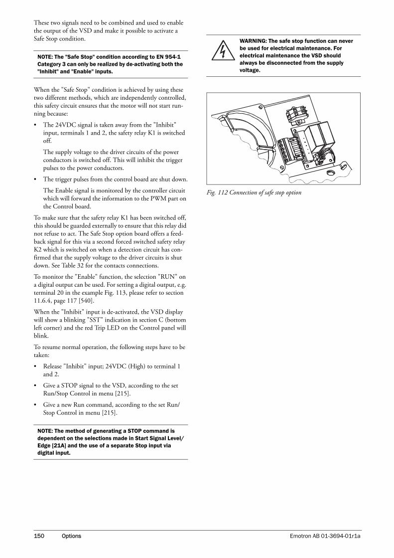
150 Options Emotron AB 01-3694-01r1a
These two signals need to be combined and used to enable the output of the VSD and make it possible to activate a Safe Stop condition.
When the "Safe Stop" condition is achieved by using these two different methods, which are independently controlled, this safety circuit ensures that the motor will not start run-ning because:
• The 24VDC signal is taken away from the "Inhibit" input, terminals 1 and 2, the safety relay K1 is switched off.
The supply voltage to the driver circuits of the power conductors is switched off. This will inhibit the trigger pulses to the power conductors.
• The trigger pulses from the control board are shut down.
The Enable signal is monitored by the controller circuit which will forward the information to the PWM part on the Control board.
To make sure that the safety relay K1 has been switched off, this should be guarded externally to ensure that this relay did not refuse to act. The Safe Stop option board offers a feed-back signal for this via a second forced switched safety relay K2 which is switched on when a detection circuit has con-firmed that the supply voltage to the driver circuits is shut down. See Table 32 for the contacts connections.
To monitor the "Enable" function, the selection "RUN" on a digital output can be used. For setting a digital output, e.g. terminal 20 in the example Fig. 113, please refer to section 11.6.4, page 117 [540].
When the "Inhibit" input is de-activated, the VSD display will show a blinking "SST" indication in section C (bottom left corner) and the red Trip LED on the Control panel will blink.
To resume normal operation, the following steps have to be taken:
• Release "Inhibit" input; 24VDC (High) to terminal 1 and 2.
• Give a STOP signal to the VSD, according to the set Run/Stop Control in menu [215].
• Give a new Run command, according to the set Run/Stop Control in menu [215].
Fig. 112 Connection of safe stop option
NOTE: The "Safe Stop" condition according to EN 954-1 Category 3 can only be realized by de-activating both the "Inhibit" and "Enable" inputs.
NOTE: The method of generating a STOP command is dependent on the selections made in Start Signal Level/Edge [21A] and the use of a separate Stop input via digital input.
WARNING: The safe stop function can never be used for electrical maintenance. For electrical maintenance the VSD should always be disconnected from the supply voltage.

Emotron AB 01-3694-01r1a Options 151
Fig. 113
13.10 Crane option boardThis option is used in crane applications. The crane option board 2.0 is described in a separate manual.
13.11 PTC, PT100, EncoderThe PTC, PT100, Encoder 2.0 option board is described in a separate manual.
=
~
=
X1
1
2
3
4
5
6
U
V
W
10
20
X1
Safe Stop +5V
+24 VDC
K1
K2
Power board
PWMControllerDigIn
DigOut
Enable
Stop
Table 32 Specification of Safe Stop option board
X1 pin
Name Function Specification
1 Inhibit + Inhibit driver circuits of power conductors
DC 24 V (20–30 V)2 Inhibit -
3NO contact relay K2 Feedback; confirmation
of activated inhibit48 VDC/30 VAC/2 A
4P contact relay K2
5 GND Supply ground
6 +24 VDC Supply Voltage for oper-ating Inhibit input only.
+24 VDC, 50 mA

152 Options Emotron AB 01-3694-01r1a

Emotron AB 01-3694-01r1a Technical Data 153
14. Technical Data
14.1 Electrical specifications related to model
Table 1 Typical motor power at mains voltage 400 V
ModelMax. output
current for 60 s [Arms]
Normal duty (120%) Heavy duty (150%)
Frame sizePower @400V [kW]
Rated current [Arms]
Power @400V [kW]
Rated current [A]
FDU40-003 3.0 0.75 2.5 0.55 2
X1
FDU40-004 4.8 1.5 4 1.1 3.2
FDU40-006 7.2 2.2 6 1.5 4.8
FDU40-008 9.0 3 7.5 2.2 6
FDU40-010 11.4 4 9.5 3 7.6
FDU40-013 15.6 5.5 13 4 10.4
FDU40-018 22 7.5 18 5.5 14.4
S2FDU40-026 31 11 26 7.5 21
FDU40-031 37 15 31 11 25
FDU40-037 44 18.5 37 15 29.60
FDU40-046 55 22 46 18.5 37
X2FDU40-060 73 30 61 22 49
FDU40-073 89 37 74 30 59
FDU48-090 108 45 90 37 72
EFDU48-109 131 55 109 45 87
FDU48-146 175 75 146 55 117
FDU48-175 210 90 175 75 140
FDU48-210 252 110 210 90 168F
FDU48-250 300 132 250 110 200

154 Technical Data Emotron AB 01-3694-01r1a
Table 2 Typical motor power at mains voltage 460 V
ModelMax. output
current for 60 s [Arms]
Normal duty (120%) Heavy duty (150%)
Frame sizePower @460 V [hp]
Rated current [Arms]
Power @460V [hp]
Rated current [A]
FDU50-018 22 15 18 7.5 14.4
S2FDU50-026 31 20 26 15 21
FDU50-031 37 25 31 20 25
FDU50-037 44 30 37 25 29.60
FDU50-046 55 40 46 30 37X2
FDU50-060 73 50 61 40 49
FDU48-090 108 75 90 60 72
EFDU48-109 131 75 109 75 87
FDU48-146 175 125 146 100 117
FDU48-175 210 150 175 125 140
FDU48-210 252 150 210 150 168F
FDU48-250 300 200 250 150 200
Table 3 Typical motor power at mains voltage 525 V
ModelMax. output
current for 60 s [Arms]
Normal duty (120%) Heavy duty (150%)
Frame sizePower @525V [kW]
Rated current [Arms]
Power @525V [kW]
Rated current [A]
FDU50-018 22 11 18 7.5 14.4
S2FDU50-026 31 15 26 11 21
FDU50-031 37 18.5 31 15 25
FDU50-037 44 22 37 18.5 29.60
FDU50-046 55 30 46 22 37X2
FDU50-060 73 37 61 30 49

Emotron AB 01-3694-01r1a Technical Data 155
14.2 General electrical specifications
Table 4 General electrical specifications
General
Mains voltage: FDU40FDU48FDU50
Mains frequency:Input power factor:Output voltage:Output frequency:Output switching frequency:Efficiency at nominal load:
380-415V +10%/-15% 380-480V +10%/-15% 440-525V +10%/-15% 45 to 65 Hz0.950–Mains supply voltage:0–400 Hz3 kHz97% for models 003 to 01398% for models 018 to 03797.5% for models 046 to 07398% for models 074 to 1k1
Control signal inputs:Analogue (differential)
Analogue Voltage/current:Max. input voltage:Input impedance:
Resolution:Hardware accuracy:Non-linearity
0-±10 V/0-20 mA via software setting+30 V/30 mA20 kΩ (voltage)250 Ω (current)11 bits + sign1% type + 1 ½ LSB fsd1½ LSB
Digital:
Input voltage:Max. input voltage:Input impedance:Signal delay:
High: >7 VDC, Low: <4 VDC+30 VDC<3.3 VDC: 4.7 kΩ ≥3.3 VDC: 3.6 kΩ≤8 ms
Control signal outputsAnalogue
Output voltage/current:Max. output voltage:Short-circuit current (∞):Output impedance:Resolution:Maximum load impedance for currentHardware accuracy:Offset:Non-linearity:
0-10 V/0-20 mA via switch+15 V @5 mA cont.+15 mA (voltage), +140 mA (current)10 Ω (voltage)10 bit500 Ω1.9% type fsd (voltage), 2.4% type fsd (current)3 LSB2 LSB
Digital
Output voltage:
Shortcircuit current(∞):
High: >20 VDC @50 mA, >23 VDC openLow: <1 VDC @50 mA100 mA max (together with +24 VDC)
Relays
Contacts 0.1 – 2 A/Umax 250 VAC or 42 VDC
References
+10VDC-10VDC+24VDC
+10 VDC @10 mA Shortcircuit current +30 mA max-10 VDC @10 mA+24 VDC Short-circuit current +100 mA max (together with Digital Outputs)

156 Technical Data Emotron AB 01-3694-01r1a
14.3 Operation at higher temperatures
Most Emotron variable speed drives are made for operation at maximum of 40°C ambient temperature. However, for most models, it is possible to use the VSD at higher temper-atures with little loss in performance. Table 33 shows ambi-ent temperatures as well as derating for higher temperatures.
ExampleIn this example we have a motor with the following data that we want to run at the ambient temperature of 45°C:
Voltage 400 VCurrent 68 APower 37 kW
Select variable speed driveThe ambient temperature is 5 °C higher than the maximum ambient temperature. The following calculation is made to select the correct VSD model.
Derating is possible with loss in performance of 2.5%/°C.
Derating will be: 5 X 2.5% = 12.5%
Calculation for model FDU40-07373 A - (12.5% X 73) = 63.875A; this is not enough.
Calculation for model FDU48-09090 A - (12.5% X 90) = 78.75 A
In this example we select the FDU48-090.
14.4 Operation at higher switching frequency
Table 6 shows the switching frequency for the different VSD models. With the possibility of running at higher switching frequency you can reduce the noise level from the motor.
Table 5 Ambient temperature and derating 400–500 V types
Model IP20 IP23/IP54
Max temp. Derating: possible Max temp. Derating: possible
FDU40-003 to FDU40-010 50°C No 45°C No
FDU40-013 40°C -2.5%/°C to max +10°C 35°C -2.5%/°C to max +10°C
FDU**-018 to FDU**-037 – – 40°C -2.5%/°C to max +10°C
FDU**-046 to FDU40-073 40°C -2.5%/°C to max +10°C 35°C -2.5%/°C to max +10°C
FDU**-074 47°C -2.5%/°C to max +3°C 42°C -2.5%/°C to max +3°C
FDU**-90 to FDU**-1500 40°C
Table 6 Switching frequency
Models400 to 690 V
Standard Switching frequency
Range
FDU40-003 to FDU40-010FDU40-013
3 kHz 1.5–6 kHz
FDU**-018 to FDU**-037 3 kHz 1.5–6 kHz
FDU**-046 to FDU40-073 3 kHz 1.5–6 kHz
FDU**-074FDU**-090FDU40-108
3 kHz 1.5–6 kHz
FDU**-90 to FDU**-1500 3 kHz 1.5–3 kHz

Emotron AB 01-3694-01r1a Technical Data 157
14.5 Dimensions and WeightsThe table below gives an overview of the dimensions and weights. The models 300 to 1500 consist of 2 or 3 parallel-led variable speed drives built into a standard cabinet.
14.6 Environmental conditions
Table 7 Mechanical specifications
ModelsFrame
sizeDim. H x W x D [mm]
IP20Dim. H x W x D [mm]
IP23/IP54Weight IP20
[kg]Weight IP23/
IP54 [kg]
003 to 013 X1 350(400)x 220 x 150 350(400)x 220 x 150 10 10
018 to 037 S2 – 470(530) x 176 x 272 – 19 (IP54)
046 to 073 X2 530(590) x 220 x 270 530(590) x 220 x 270 26 26
90 to 109 E – 950 x 285 x 310 – 56
146 to 175 E – 950 x 285 x 310 – 59,5
210 to 250 F – 950 x 345 x 310 – 74
Table 8 Operation
Parameter Normal operation
Nominal ambient temperature 40°C See table, see Table 5 for different conditions
Atmospheric pressure 86–106 kPa
Relative humidity, non-condensing 0–90%
Contamination, according to IEC 60721-3-3
No electrically conductive dust allowedCooling air must be clean and free from corrosive materialsChemical gases, class 3C2Solid particles, class 3S2
Shock and vibrations
Mechanical conditions according to IEC 60721-3-3, Class M4Sinusodial vibrations:•2–9 Hz, 3.0 mm•9–200 Hz, 10 m/s2
Shock:shock response spectrum type IMax. 100 m/s2
Altitude 0–1000 m, with derating of output up to 2000 m.
Table 9 Storage
Parameter Storage condition
Temperature -20 to +60 °C
Atmospheric pressure 86–106 kPa
Relative humidity, non-condensing 0– 90%

158 Technical Data Emotron AB 01-3694-01r1a
14.7 Fuses, cable cross-sections and glands
Use mains fuses of the type gL/gG conforming to IEC 269 or installation cut-outs with similar characteristics. Check the equipment first before installing the glands. In due time only metric glands will be used.
Max. Fuse = maximum fuse value that still protects the VSD and upholds warranty.
NOTE: The dimensions of fuse and cable cross-section are dependent on the application and must be determined in accordance with local regulations.
NOTE: The dimensions of the power terminals used in the models 300 to 1500 can differ depending on customer specification.
Table 10 Fuses, cable cross-sections and glands
Model Nominal
input current [A]
Maximum value fuse
[A]
Maximum cable cross-section
connector [mm2]Clamping range glands [mm] Frame
size
Mains Motor Mains Motor
FDU40-003FDU40-004FDU40-006FDU40-008FDU40-010FDU40-013
2356811
66
10101616
6 6 M20 (7–13) M20 (8.5–13) X1
FDU**-018FDU**-026FDU**-031FDU**-037
1116222631
1620253535
16 16 Ø32 (cable entry) Ø32 (cable entry) S2
FDU**-046FDU**-060FDU**-073
385164
506380
162550
162550
M40 (19 - 28) M40 (27 - 34) X2
FDU**-090 FDU**-109FDU**-146FDU**-175
7894126152
100100160160
35–150 35–150Ø30–45 cable
entry or M63 (34–45)
Ø30–45 cable entry or
M63 (34–45)E
FDU**-210FDU**-250
182216
200250
35–240 35–240Ø27–66 cable
entryØ27–66 cable
entryF

Emotron AB 01-3694-01r1a Technical Data 159
14.8 Control signals
Table 11
Terminal Name: Function (Default): Signal: Type:
1 +10 V +10 VDC Supply voltage +10 VDC, max 10 mA output
2 AnIn1 Process reference0 -10 VDC or 0/4–20 mAbipolar: -10 - +10 VDC or -20 - +20 mA
analogue input
3 AnIn2 Off0 -10 VDC or 0/4–20 mAbipolar: -10 - +10 VDC or -20 - +20 mA
analogue input
4 AnIn3 Off0 -10 VDC or 0/4–20 mAbipolar: -10 - +10 VDC or -20 - +20 mA
analogue input
5 AnIn4 Off0 -10 VDC or 0/4–20 mAbipolar: -10 - +10 VDC or -20 - +20 mA
analogue input
6 -10 V -10VDC Supply voltage -10 VDC, max 10 mA output
7 Common Signal ground 0V output
8 DigIn 1 RunL 0-8/24 VDC digital input
9 DigIn 2 RunR 0-8/24 VDC digital input
10 DigIn 3 Off 0-8/24 VDC digital input
11 +24 V +24VDC Supply voltage +24 VDC, 100 mA output
12 Common Signal ground 0 V output
13 AnOut 1 Min speed to max speed 0 ±10 VDC or 0/4– +20 mA analogue output
14 AnOut 2 0 to max torque 0 ±10 VDC or 0/4– +20 mA analogue output
15 Common Signal ground 0 V output
16 DigIn 4 Off 0-8/24 VDC digital input
17 DigIn 5 Off 0-8/24 VDC digital input
18 DigIn 6 Off 0-8/24 VDC digital input
19 DigIn 7 Off 0-8/24 VDC digital input
20 DigOut 1 Ready 24 VDC, 100 mA digital output
21 DigOut 2 Brake 24 VDC, 100 mA digital output
22 DigIn 8 RESET 0-8/24 VDC digital input
Terminal X2
31 N/C 1 Relay 1 outputTrip, active when theVSD is in a TRIP conditionN/C is opened when the relay is active (valid for all relays)N/O is closed when the relay is active (valid for all relays)
potential free change over0.1 – 2 A/Umax 250 VAC or 42 VDC
relay output
32 COM 1
33 N/O 1
41 N/C 2Relay 2 OutputRun, active when theVSD is started
potential free change over0.1 – 2 A/Umax 250 VAC or 42 VDC
relay output42 COM 2
43 N/O 2
Terminal X3
51 COM 3 Relay 3 OutputOff
potential free change over0.1 – 2 A/Umax 250 VAC or 42 VDC
relay output52 N/O 3

160 Technical Data Emotron AB 01-3694-01r1a

Emotron AB 01-3694-01r1a Menu List 161
15. Menu List
DEFAULT CUSTOM
100 Preferred View
110 1st Line Process Val
120 2nd Line Current
200 Main Setup
210 Operation
211 Language English
212 Motor Select M1
213 Drive Mode V/Hz
214 Ref Control Remote
215 Run/Stp Ctrl Remote
216 Reset Ctrl Remote
217 LOC/REM Off
218 Lock Code? 0
219 Rotation R+L
21A Level/Edge Level
220 Motor Data
221 Motor Volts UnomVAC
222 Motor Freq 50Hz
223 Motor Power (PNOM)kW
224 Motor Current (INOM)A
225 Motor Speed (nMOT) rpm
226 Motor Poles -
227 Motor Cosϕ Depends on Pnom
228 Motor Vent Self
229 Motor ID-Run Off
22A Motor Sound F
22B Encoder Off
22C Enc Pulses 1024
22D Enc Speed XXrpm
230 Motor Protection
231 Mot I2t Type Trip
232 Mot I2t Cur (IMOT)A
233 Mot I2t Time 60s
234 PTC Off
235 Motor Class F 140°C
240 Parameter Set Handling
241 Select Set A
242 Copy Set A>B
243 Default>Set A
244 Copy to CP No Copy
245 Load from CP No Copy
250 Trip Autoreset/Trip Conditions
251 No of Trips 0
252 Overtemp Off
253 Overvolt D Off
254 Overvolt G Off
255 Overvolt Off
256 Motor Lost Off
257 Locked Rotor Off
258 Power Fault Off
259 Undervoltage Off
25A Motor I2t Off
25B Motor I2t TT Trip
25C PT100 Off
25D PT100 TT Trip
25E PTC Off
25F PTC TT Trip
25G Ext Trip Off
25H External TT Trip
25I Com Error Off
25J Com Error TT Trip
25K Min Alarm Off
25L Min Alarm TT Trip
25M Max Alarm Off
25N Max Alarm TT Trip
25O Over curr F Off
25P Pump Off
25Q Over speed Off
260 Serial Communication
261 Com Type RS232/485
262 RS232/485
2621 Baud 9600
2622 Address 1
263 Fieldbus
2631 Address 62
2632 SizeOfData 4
2633 Read/Write RW
264 Interrupt Warning
269 FB Status
300 Process & Application Parameters
310 Set/View Reference Value
320 Process Settings
321 Proc Source Speed
322 Unit rpm
323 Proc Unit Off
324 Process Min 0
325 Process Max 0
326 Ratio Linear
327 Proc Min Min
328 Proc Max Max
330 Start/Stop settings
331 Acc Time 10.00s
332 Dec Time 10.00s
333 Acc MotPot 16.00s
334 Dec MotPot 16.00s
335 Acc>Min Spd 10.00s
336 Dec<Min Spe 10.00s
337 Acc Rmp Linear
338 Dec Rmp Linear
339 Start Mode Fast
33A Spinstart Off
33B Stop Mode Decel
33C Brk Release 0.00s
33D Release Spd 10rpm
33E Brk Engage 0.00s
DEFAULT CUSTOM

162 Menu List Emotron AB 01-3694-01r1a
33F Brk Wait 0.00s
33G Vector Brake Off
340 Speeds
341 Min Speed 0rpm
342 Stp<MinSpd Off
343 Max Speed rpm
344 SkipSpd 1 Lo 0rpm
345 SkipSpd 1 Hi 0rpm
346 SkipSpd 2 Lo 0rpm
347 SkipSpd 2 Hi 0rpm
348 Jog Speed 50rpm
350 Torques
351 Max Torque 120%
352 IxR Comp Automatic
353 IxR CompUsr 0.0%
354 Flux optim Off
360 Preset References
361 Motor Pot Non Vola
362 Preset Ref 1 0 rpm
363 Preset Ref 2 250 rpm
364 Preset Ref 3 500 rpm
365 Preset Ref 4 750 rpm
366 Preset Ref 5 1000 rpm
367 Preset Ref 6 1250 rpm
368 Preset Ref 7 1500 rpm
380 PID Process control
381 PID Control Off
383 PID P Gain 1.0
384 PID I Time 1.00s
385 PID D Time 0.00s
390 Pump/Fan Control
391 Ctrl Status Off
392 No of Drives 2
393 Select Drive Sequence
394 Change Cond Both
395 Change Timer 50h
396 Drives on Ch 0
397 Upper Band 10%
398 Lower Band 10%
399 Start Delay 0s
39A Stop Delay 0s
39B Upp Band Lim 0%
39C Low Band Lim 0%
39D Settle Start 0s
39E TransS Start 60%
39F Settle Stop 0s
39G TransS Stop 60%
39H Run Time 1 h:m
39H1 Rst Run Time No
39I Run Time 2 h:m
39I1 Rst Run Time No
39J Run Time 3 h:m
39J1 Rst Run Time No
39K Run Time 4 h:m
DEFAULT CUSTOM
39K1 Rst Run Time No
39L Run Time05 h:m
39L1 Rst Run Time No
39M Run Time 6 h:m
39M1 Rst Run Time No
39N Pump Status STPD 0
400 Load Monitor and Process protection
410 Load Monitor
411 Alarm Select Off
412 Alarm trip Off
413 Ramp Alarm Off
414 Start Delay 2s
415 Load Type Basic
416 Max Alarm
4161 MaxAlarm Ma 15%
4162 MaxAlarm De 0.1s
417 Max Pre alarm
4171 MaxPreAl Ma 10%
4172 MaxPreAl De 0.1s
418 Min Pre Alarm
4181 MinPreAl Ma 10%
4182 MinPreAl De 0.1s
419 Min Alarm
4191 MinAlarm Ma 15%
4192 MinAlarm De 0.1s
41A AutoSet Alrm No
41B Normal Load 100%
41C Load Curve
41C1 Load Curve 1
41C2 Load Curve 2
41C3 Load Curve 3
41C4 Load Curve 4
41C5 Load Curve 5
41C6 Load Curve 6
41C7 Load Curve 7
41C8 Load Curve 8
41C9 Load Curve 9
420 Process Protection
421 Low Volt OR On
422 Rotor Locked Off
423 Motor lost Off
424 Overvolt Ctrl Off
500 I/Os and Virtual Connections
510 Analogue Inputs
511 AnIn1 Fc Process Ref
512 AnIn1 Setup 0-10V/0-20mA
513 AnIn1 Advn
5131 AnIn1 Min 0V/4.00mA
5132 AnIn1 Max 10.0V/20.00mA
5133 AnIn1 Bipol 10.00V
5134 AnIn1 FcMin Min
5135 AnIn1 ValMin
5136 AnIn1 FcMax Max
5137 AnIn1 ValMax
DEFAULT CUSTOM

Emotron AB 01-3694-01r1a Menu List 163
5138 AnIn1 Oper Add+
5139 AnIn1 Filt 0.01s
514 AnIn2 Fc Off
515 AnIn2 Setup 4-20mA
516 AnIn2 Advan
5161 AnIn1 Min 0V/4.00mA
5162 AnIn1 Max 10.0V/20.00mA
5163 AnIn1 Bipol 10.00V
5164 AnIn1 FcMin Min
5165 AnIn1 ValMin
5166 AnIn1 FcMax Max
5167 AnIn1 ValMax
5168 AnIn1 Oper Add+
5169 AnIn1 Filt 0.01s
517 AnIn3 Fc Off
518 AnIn3 Setup 4-20mA
519 AnIn3 Advan
5191 AnIn1 Min 0V/4.00mA
5192 AnIn1 Max 10.0V/20.00mA
5193 AnIn1 Bipol 10.00V
5194 AnIn1 FcMin Min
5195 AnIn1 ValMin
5196 AnIn1 FcMax Max
5197 AnIn1 ValMax
5198 AnIn1 Oper Add+
5199 AnIn1 Filt 0.01s
51A AnIn4 Fc Off
51B AnIn4 Setup 4-20mA
51C AnIn4 Advan
51C1 AnIn1 Min 0V/4.00mA
51C2 AnIn1 Max 10.0V/20.00mA
51C3 AnIn1 Bipol 10.00V
51C4 AnIn1 FcMin Min
51C5 AnIn1 ValMin
51C6 AnIn1 FcMax Max
51C7 AnIn1 ValMax
51C8 AnIn1 Oper Add+
51C9 AnIn1 Filt 0.01s
520 Digital Inputs
521 DigIn 1 RunL
522 DigIn 2 RunR
523 DigIn 3 Off
524 DigIn 4 Off
525 DigIn 5 Off
526 DigIn 6 Off
527 DigIn 7 Off
528 DigIn 8 Reset
529 Board 1 DigIn 1
52A Board 1 DigIn 2
52B Board 1 DigIn 3
52C Board 2 DigIn 1
52D Board 2 DigIn 2
52E Board 2 DigIn 3
52F Board 3 DigIn 1
DEFAULT CUSTOM
52G Board 3 DigIn 2
52H Board 3 DigIn 3
530 Analogue Outputs
531 AnOut1 Fc Speed
532 AnOut1 Setup 0-10V/0-20mA
533 AnOut1 Adv
5331 AnOut 1 Min 0V/4mA
5332 AnOut 1 Max 10.00V/20.0mA
5333 AnOut1Bipol -10.00-10.00V
5334 AnOut1 FcMin Min
5335 AnOut1 VlMin
5336 AnOut1 FcMax Max
5337 AnOut1 VlMax
534 AnOut2 FC Torque
535 AnOut2 Setup 4-20mA
536 AnOut2 Advan
5361 AnOut 2 Min 0V/4mA
5362 AnOut 2 Max 10.00V/20.0mA
5363 AnOut2Bipol -10.00-10.00V
5364 AnOut2 FcMin Min
5365 AnOut2 VlMin
5366 AnOut2 FcMax Max
5367 AnOut2 VlMax
540 Digital Outputs
541 DigOut 1 Run
542 DigOut 2 No Trip
550 Relays
551 Relay 1 Trip
552 Relay 2 Ready
553 Relay 3 Off
554 Board 1 Relay 1
555 Board 1 Relay 2
556 Board 1 Relay 3
557 Board 2 Relay 1
558 Board 2 Relay 2
559 Board 2 Relay 3
55A Board 3 Relay 1
55B Board 3 Relay 2
55C Board 3 Relay 3
55D Rrlay Adv
55D1 Relay 1 Mode N.O
55D2 Relay 2 Mode
55D3 Relay 3 Mode
55D4 B1R1 Mode
55D5 B1R2 Mode
55D6 B1R3 Mode
55D7 B2R1 Mode
55D8 B2R2 Mode
55D9 B2R3 Mode
55DA B3R1 Mode
55DB B3R2 Mode
55DC B3R3 Mode
560 virtual Connections
561 VIO 1 Dest Off
DEFAULT CUSTOM

164 Menu List Emotron AB 01-3694-01r1a
562 VIO 1 Source Off
563 VIO 2 Dest Off
564 VIO 2 Source Off
565 VIO 3 Dest Off
566 VIO 3 Source Off
567 VIO 4 Dest Off
568 VIO 4 Source Off
569 VIO 5 Dest Off
56A VIO 5 Source Off
56B VIO 6 Dest Off
56C VIO 6 Source Off
56D VIO 7 Dest Off
56E VIO 7 Source Off
56F VIO 8 Dest Off
56G VIO 8 Source Off
600 Logical Functions and Timers
610 Comparators
611 CA1 Value Speed
612 CA1 Level HI 300rpm
613 CA1 Level LO 200rpm
614 CA2 Value Torque
615 CA2 Level HI 20%
616 CA2 Level LO 10%
617 CD1 Run
618 CD2 DigIn 1
620 Logic Output Y
621 Y Comp 1 CA1
622 Y Operator 1 &
623 Y Comp 2 !A2
624 Y Operator 2 &
625 Y Comp 3 CD1
630 Logic Output Z
631 Z Comp 1 CA1
632 Z Operator 1 &
633 Z comp2 !A1
634 Z Operator 2 &
635 Z Comp 3 CD1
640 Timer1
641 Timer1 Trig Off
642 Timer1 Mode Off
643 Timer1Delay 0:00:00
644 Timer 1 T1 0:00:00
645 Timer1 T1 0:00:00
650 Timer2
651 Timer2 Trig Off
652 Timer2 Mode Off
653 Timer2Delay 0:00:00
654 Timer 2 T1 0:00:00
655 Timer2 T1 0:00:00
700 View operation/Status
710 Operation ...............Hz
711 Process Val
712 Speed rpm
713 Torque %Nm
DEFAULT CUSTOM
714 Shaft power kW
715 Electrical Power kW
716 Current A
717 Output volt V
718 Frequency Hz
719 DC Voltage V
71A Heatsink Tmp °C
71B PT100_1_2_3 Temp °C
720 Status ..........%Nm
721 VSD Status
722 Warnings
723 DigIn Status
724 DigOut Status
725 AnIn Status 1-2
726 AnIn Status 3-4
727 AnOut Status
728 I/O board 1 Status
729 I/O board 2 Status
72A I/O board 3 Status
730 Stored values ............kW
731 Run Time h.....m.........
7311 Reset Run Tm No
732 Mains Time ................
733 Energy ........ARMS
7331 Reset Energy No
800 View Trip Log
810 Trip Message
811 Process Value h:m
812 Speed
813 Torque
814 Shaft Power
815 Electrical Power
816 Current
817 Output voltage
818 Frequency
819 DC Link voltage
81A Heatsink Temperature
81B PT100_1, 2, 3
81C FI Status
81D Digital input status
81E Digital output status
81F Analogue input status 1-2
81G Analogue input status 3-4
81H Analogue output status 1-2
81I I/O status option board 1
81J I/O status option board 2
81K I/O status option board 3
81L Run Time
81M Mains Time
81N Energy
820 Trip Message h:m
821 Process Value h:m
822 Speed
823 Torque
DEFAULT CUSTOM

Emotron AB 01-3694-01r1a Menu List 165
824 Shaft Power
825 Electrical Power
826 Current
827 Output voltage
828 Frequency
829 DC Link voltage
82A Heatsink Temperature
82B PT100_1, 2, 3
82C FI Status
82D Digital input status
82E Digital output status
82F Analogue input status 1-2
82G Analogue input status 3-4
82H Analogue output status 1-2
82I I/O status option board 1
82J I/O status option board 2
82K I/O status option board 3
82L Run Time
82M Mains Time
82N Energy
830
831 Process Value h:m
832 Speed
833 Torque
834 Shaft Power
835 Electrical Power
836 Current
837 Output voltage
838 Frequency
839 DC Link voltage
83A Heatsink Temperature
83B PT100_1, 2, 3
83C FI Status
83D Digital input status
83E Digital output status
83F Analogue input status 1-2
83G Analogue input status 3-4
83H Analogue output status 1-2
83I I/O status option board 1
83J I/O status option board 2
83K I/O status option board 3
83L Run Time
83M Mains Time
83N Energy
840
841 Process Value h:m
842 Speed
843 Torque
844 Shaft Power
845 Electrical Power
846 Current
847 Output voltage
848 Frequency
849 DC Link voltage
DEFAULT CUSTOM
84A Heatsink Temperature
84B PT100_1, 2, 3
84C FI Status
84D Digital input status
84E Digital output status
84F Analogue input status 1-2
84G Analogue input status 3-4
84H Analogue output status 1-2
84I I/O status option board 1
84J I/O status option board 2
84K I/O status option board 3
84L Run Time
84M Mains Time
84N Energy
850
851 Process Value h:m
852 Speed
853 Torque
854 Shaft Power
855 Electrical Power
856 Current
857 Output voltage
858 Frequency
859 DC Link voltage
85A Heatsink Temperature
85B PT100_1, 2, 3
85C FI Status
85D Digital input status
85E Digital output status
85F Analogue input status 1-2
85G Analogue input status 3-4
85H Analogue output status 1-2
85I I/O status option board 1
85J I/O status option board 2
85K I/O status option board 3
85L Run Time
85M Mains Time
85N Energy
860
861 Process Value h:m
862 Speed
863 Torque
864 Shaft Power
865 Electrical Power
866 Current
867 Output voltage
868 Frequency
869 DC Link voltage
86A Heatsink Temperature
86B PT100_1, 2, 3
86C FI Status
86D Digital input status
86E Digital output status
86F Analogue input status 1-2
DEFAULT CUSTOM

166 Menu List Emotron AB 01-3694-01r1a
86G Analogue input status 3-4
86H Analogue output status 1-2
86I I/O status option board 1
86J I/O status option board 2
86K I/O status option board 3
86L Run Time
86M Mains Time
86N Energy
870
871 Process Value h:m
872 Speed
873 Torque
874 Shaft Power
875 Electrical Power
876 Current
877 Output voltage
878 Frequency
879 DC Link voltage
87A Heatsink Temperature
87B PT100_1, 2, 3
87C FI Status
87D Digital input status
87E Digital output status
87F Analogue input status 1-2
87G Analogue input status 3-4
87H Analogue output status 1-2
87I I/O status option board 1
87J I/O status option board 2
87K I/O status option board 3
87L Run Time
87M Mains Time
87N Energy
880
881 Process Value h:m
882 Speed
818 Torque
884 Shaft Power
885 Electrical Power
886 Current
887 Output voltage
888 Frequency
889 DC Link voltage
88A Heatsink Temperature
88B PT100_1, 2, 3
88C FI Status
88D Digital input status
88E Digital output status
88F Analogue input status 1-2
88G Analogue input status 3-4
88H Analogue output status 1-2
88I I/O status option board 1
88J I/O status option board 2
88K I/O status option board 3
88L Run Time
DEFAULT CUSTOM
88M Mains Time
88N Energy
890
891 Process Value h:m
892 Speed
893 Torque
894 Shaft Power
895 Electrical Power
896 Current
897 Output voltage
898 Frequency
899 DC Link voltage
89A Heatsink Temperature
89B PT100_1, 2, 3
89C FI Status
89D Digital input status
89E Digital output status
89F Analogue input status 1-2
89G Analogue input status 3-4
89H Analogue output status 1-2
89I I/O status option board 1
89J I/O status option board 2
89K I/O status option board 3
89L Run Time
89M Mains Time
89N Energy
8A0 Reset Trip No
900 System Data
920 VSD Data ...............
921 VSD Type
922 Software
923 Unit name
DEFAULT CUSTOM

Emotron AB 01-3694-01r1a 167
Index
Symbols+10VDC Supply voltage ................159+24VDC supply voltage ................159
Numerics0-10V ..............................................220-20mA ...........................................22-10VDC supply voltage .................1594-20mA .........................................108
AAcceleration ...............................83, 85
Acceleration ramp .....................85Acceleration time ......................83Ramp type ................................85
Alarm trip ......................................101Alternating MASTER ....39, 42, 43, 95Ambient temperature and derating 156Analogue comparators ...................121Analogue input ..............................106
AnIn1 .....................................106AnIn2 .............................111, 112Offset .............................107, 114
Analogue Output ...........114, 117, 159AnOut 1 .........................114, 117Output configuration .....114, 117
AND operator ...............................125AnIn1 ............................................106AnIn2 ............................................111AnIn3 ............................................111AnIn4 ............................................112Autoreset .......................1, 34, 71, 142
BBaudrate ..............................52, 77, 78Brake chopper ................................148Brake function ...........................86, 87
Brake ........................................87Brake Engage Time ..................87BRAKE RELEASE TIME ........86BRAKE WAIT TIME ..............88Release speed ............................87Vector Brake .............................88
Brake functionsFrequency ...............................106
Brake resistors ................................148
CCable cross-section .........................158Cascade controller ............................38CE-marking .......................................6Change Condition ...........................95Change Timer ...........................95, 96CHECKLIST ..................................43Clockwise rotary field ....................113Comparators ..................................121
ConnectionsBrake chopper connections .......15Control signal connections ........22Mains supply ......................15, 25Motor earth ........................15, 25Motor output ......................15, 25Safety earth .........................15, 25
Control Panel memory .....................36Copy all settings to Control Panel .70Frequency ...............................106
Control signal connections ...............22Control signals ...........................20, 23
Edge-controlled ..................35, 63Level-controlled ..................34, 63
Counter-clockwise rotary field .......113Current ............................................52Current control (0-20mA) ...............23
DDeceleration .....................................83
Deceleration time .....................83Ramp type ................................85
Declaration of Conformity .................6Default .............................................70Definitions .........................................7Derating .........................................156Digital comparators ........................121Digital inputs
DigIn 1 ...................................112DigIn 2 ...........................113, 119DigIn 3 ...................................113
Dismantling and scrapping ................7Display .............................................49Double-ended connection ................23Drive ................................................60Drive mode
Frequency ...............................106Drives on Change ......................95, 96
EECP ...............................................147Edge control ...............................35, 63Electrical specification ....................155EMC ................................................13
Current control (0-20mA) ........23Double-ended connection .........23EMC-directives .........................22RFI mains filter .........................13Single-ended connection ...........23Twisted cables ...........................24
Emergency stop ................................47EN50178 ...........................................6EN60204-1 ........................................6EN61800-3 ........................................6Enable ................................33, 50, 113EXOR operator ..............................125
Expression ..................................... 125External Control Panel .................. 147
FFactory settings ................................ 70Fail safe ........................................... 40Fans ................................................. 94Feedback 'Status' input .................... 39Fieldbus ................................... 78, 149Fixed MASTER ................... 43, 94, 95Flux optimization ............................ 92Frequency ...................................... 130
Frequency priority .................... 32Jog Frequency .......................... 90Maximum Frequency ......... 88, 89Minimum Frequency ............... 88Preset Frequency ...................... 92Skip Frequency ........................ 89
Frequency priority ........................... 32Fuses, cable cross-sections and glands ..158
GGeneral electrical specifications ..... 155
HHydrophore controller .................... 38
II/O Board ...................................... 149I2t protection
Motor I2t Current ............. 67, 69Motor I2t Type ........................ 67
ID run ....................................... 35, 65Identification Run ..................... 35, 65IEC269 ......................................... 158Interrupt ......................................... 78IP20 .............................................. 147IP54 .............................................. 147IT Mains supply ................................ 2IxR Compensation .......................... 91
JJog Frequency ................................. 90
KKeys ................................................ 50
- Key ........................................ 51+ Key ....................................... 51Control keys ............................. 50ENTER key ............................. 51ESCAPE key ............................ 51Function keys ....................... 6, 51NEXT key ................................ 51PREVIOUS key ....................... 51RUN L ..................................... 50

168 Emotron AB 01-3694-01r1a
RUN R .....................................50STOP/RESET ..........................50Toggle Key ...............................50
LLCD display ....................................49Level control ..............................34, 63Load default .....................................70Load monitor ...........................36, 101Lock Code .......................................62Long motor cables ...........................15Low Voltage Directive .......................6Lower Band .....................................96Lower Band Limit ............................98
MMachine Directive .............................6Mains cable ....................................158Mains supply .......................15, 19, 25Maintenance ..................................145Manufacturer’s certificate ...................6Max Frequency ....................83, 88, 89Memory ...........................................36Menu
(110) ........................................59(120) ........................................59(210) ........................................60(211) ........................................60(212) ........................................60(213) ........................................60(214) ........................................61(215) ........................................61(216) ........................................61(217) ........................................61(218) ........................................62(219) ........................................62(21A) ........................................63(220) ........................................63(221) ........................................63(222) ........................................63(223) ........................................64(224) ........................................64(225) ........................................64(226) ........................................64(227) ........................................64(228) ........................................65(229) ........................................65(22A) ........................................66(22B) ........................................66(22C) ........................................66(22D) .......................................66(231) ........................................67(232) ........................................67(233) ........................................67(234) ........................................68(235) ........................................69(240) ........................................69(241) ........................................69(242) ........................................70(243) ........................................70
(244) .........................................70(245) .........................................70(250) .........................................71(251) .........................................71(252) .........................................72(253) .........................................72(254) .........................................72(255) .........................................72(256) .........................................73(257) .........................................73(258) .........................................73(259) .........................................73(25A) ........................................74(25B) ........................................74(25C) ........................................74(25D) ........................................74(25E) ........................................74(25F) ........................................75(25G) ........................................75(25H) .......................................75(25I) .........................................75(25J) .........................................75(25K) ........................................76(25L) ........................................76(25M) .......................................76(25N) .................................71, 76(25O) .......................................76(25P) ........................................77(25Q) .......................................77(260) .........................................77(261) .........................................77(262) .........................................77(2621) .......................................77(2622) .......................................77(263) .........................................78(2631) .......................................78(2632) .......................................78(2633) .......................................78(264) .........................................78(269) .........................................78(310) .........................................79(321) .........................................79(322) .........................................80(323) .........................................80(324) .........................................81(325) .........................................81(326) .........................................81(327) .........................................82(328) .........................................82(331) .........................................83(332) .........................................83(333) .........................................84(334) .........................................84(335) .........................................84(336) .........................................84(337) .........................................85(338) .........................................85(339) .........................................85(33A) ........................................86(33B) ........................................86
(33C) ....................................... 86(33D) ....................................... 87(33E) ........................................ 87(33F) ........................................ 88(33G) ....................................... 88(341) ........................................ 88(342) ........................................ 88(343) ........................................ 89(344) ........................................ 89(345) ........................................ 89(346) ........................................ 90(347) ........................................ 90(348) ........................................ 90(351) ........................................ 90(354) ........................................ 92(361) ........................................ 92(362) ........................................ 92(363) ........................................ 93(364) ........................................ 93(365) ........................................ 93(366) ........................................ 93(367) ........................................ 93(368) ........................................ 92(380) ........................................ 93(381) ........................................ 93(383) ........................................ 93(384) ........................................ 94(385) ........................................ 94(391) ........................................ 94(392) ........................................ 94(394) ........................................ 95(39F) ........................................ 99(39G) ....................................... 99(39H-39M) ............................ 100(410) ...................................... 101(411) ...................................... 101(413) ...................................... 101(414) ...................................... 101(415) ...................................... 102(416) ...................................... 102(4162) .................................... 102(417) ...................................... 102(4172) .................................... 103(418) ...................................... 103(4182) .................................... 103(419) ...................................... 103(4192) .................................... 103(41A) ..................................... 104(41B) ...................................... 104(41C) ..................................... 104(421) ...................................... 105(422) ...................................... 105(423) ...................................... 106(424) ...................................... 106(511) ...................................... 106(512) ...................................... 107(513) ...................................... 108(514) ...................................... 111(515) ...................................... 111(516) ...................................... 111

Emotron AB 01-3694-01r1a 169
(517) ......................................111(518) ......................................111(519) ......................................112(51A) ......................................112(51B) ......................................112(51C) ......................................112(521) ......................................112(522) ......................................113(529-52H) ..............................113(531) ......................................114(532) ......................................114(533) ......................................115(534) ......................................117(535) ......................................117(536) ......................................117(541) ......................................117(542) ......................................118(551) ......................................119(552) ......................................119(553) ......................................119(55D) .....................................119(561) ......................................120(562) ......................................121(563-56G) ..............................121(610) ......................................121(611) ......................................121(612) ......................................123(613) ......................................124(614) ......................................124(615) ......................................124(616) ......................................124(617) ......................................125(618) ......................................125(620) ......................................125(621) ..............................125, 126(622) ......................................126(623) ......................................126(624) ......................................126(625) ......................................126(630) ......................................127(631) ......................................127(632) ......................................127(633) ......................................127(634) ......................................127(635) ......................................128(640) ......................................128(641) ......................................128(642) ......................................128(643) ......................................129(644) ......................................129(645) ......................................129(650) ......................................129(651) ......................................129(652) ......................................129(653) ......................................130(654) ......................................130(655) ......................................130(711) ......................................130(712) ......................................130(713) ......................................131
(714) .......................................131(715) .......................................131(716) .......................................131(717) .......................................131(718) .......................................131(719) .......................................132(71A) ......................................132(71B) ......................................132(720) .......................................132(721) .......................................132(722) .......................................133(724) .......................................134(725) .......................................134(726) .......................................134(727) .......................................134(728-72A) ...............................135(730) .......................................135(731) .......................................135(7311) .....................................135(732) .......................................135(733) .......................................136(7331) .....................................136(800) .......................................136(810) .......................................136(811) .......................................137(811-81N) ..............................137(820) .......................................137(8A0) ......................................138(900) .......................................138(920) .......................................138(922) .......................................138
Minimum Frequency .................84, 89Monitor function
Alarm Select ............................104Delay time ..............................101Max Alarm ..............................101Overload ...........................36, 101Response delay ................102, 104Start delay ...............................101
Motor cable ....................................158Motor cos phi (power factor) ...........64Motor frequency ..............................64Motor I2t Current .........................143Motor identification run ..................65Motor Potentiometer ...............92, 113Motor potentiometer .....................113Motor ventilation .............................65Motors ...............................................5Motors in parallel .............................17MotPot ............................................84Multi-motor application ..................60
NNominal motor frequency ................89Number of drives .............................94
OOperation ........................................60Options ............................................24
Brake chopper .........................148
External Control Panel (ECP) 147Protection class IP23 and IP54 .....147Serial communication, fieldbus ....149
OR operator .................................. 125Output coils .................................. 149Overload ................................. 36, 101Overload alarm ................................ 36
PParameter sets
Load default values ................... 70Load parameter sets from Control Panel ........................................ 70Parameter Set Selection ............ 31Select a Parameter set ............... 69
PID control ..................................... 41PID Controller ................................ 93
Closed loop PID control .......... 93Feedback signal ........................ 93PID D Time ............................ 94PID I Time .............................. 94PID P Gain .............................. 93
POWER LED ................................. 50Priority ............................................ 32Programming .................................. 52Protection class IP23 and IP54 ...... 147PTC input ....................................... 68Pump size ........................................ 43Pump/Fan Control .......................... 94
QQuick Setup Card ............................. 5
RReference
Frequency .............................. 105Motor potentiometer ............. 113Reference signal .................. 60, 79Set reference value .................... 79Torque ................................... 105View reference value ................. 79
Reference control ............................ 61Reference signal ............................... 61RELAY Card option ........................ 38Relay output .................................. 119
Relay 1 ................................... 119Relay 2 ................................... 119
Release speed ................................... 87Reset command ............................. 113Resolution ....................................... 59RFI mains filter ............................... 13Rotation .......................................... 62RS232/485 ...................................... 77RUN ............................................... 50Run command ................................ 50Run Left command ....................... 113Run Right command ..................... 113Running motor ............................... 86

170 Emotron AB 01-3694-01r1a
SSelect Drive ...............................94, 95Settle Time ......................................98Setup menu .....................................52
Menu structure .........................52Signal ground ................................159Single-ended connection ..................23Software .........................................138Sound characteristic .........................66Speed .............................................130Spinstart ..........................................86Standards ...........................................6Start Delay .......................................97Status indications .............................49Stop categories .................................47Stop command ..............................112Stop Delay .......................................97Stripping lengths ..............................15Switches ...........................................22Switching frequency .........................66Switching in motor cables ................15
TTest Run ..........................................65Thermal overload .............................17Timer ..............................................95Torque .............................................90Transition Frequency .......................98TRIP ...............................................50Trip causes and remedy .................142Trips, warnings and limits .............141Twisted cables ..................................24Type ..............................................138Type number .....................................5
UUnderload .......................................36Underload alarm ............................101Unlock Code ...................................62Upper Band .....................................96Upper Band Limit ...........................97
VV/Hz Mode .....................................60Vector Brake ....................................88Ventilation .......................................65View reference value ........................79
WWarning ........................................136Wiring .............................................42

Emotron AB, Mörsaregatan 12, SE-250 24 Helsingborg, SwedenTel: +46 42 16 99 00, Fax: +46 42 16 99 49
E-mail: [email protected]: www.emotron.com
Emot
ron
AB 0
1-3
694
-01
r1a
25
-08
-20
06