Embed Size (px)
Citation preview
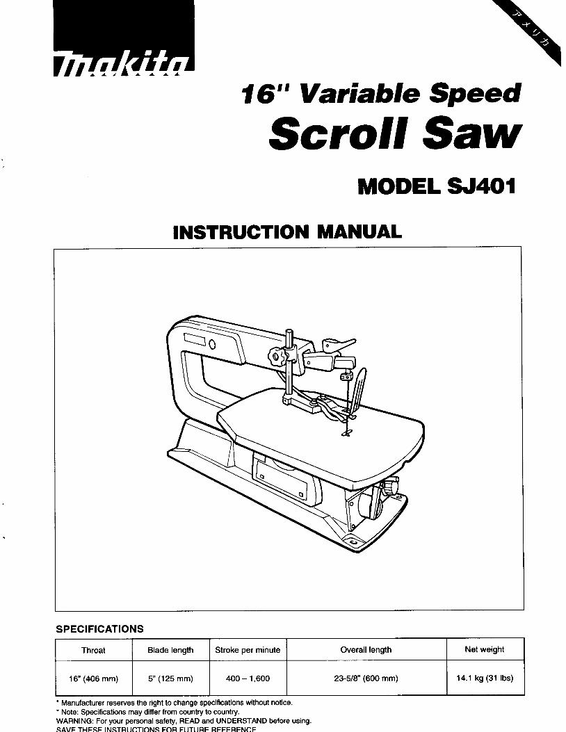
1116" Variable Speed
Throat Blade length Stroke per minute Overall length
1 6 (406 mm) 5" (125 mm) 400 - 1,600 2348" (600 mm)
Scroll Saw
Net weight
14.1 kg (31 Ibs)
INSTRUCTION MANUAL

GENERAL SAFETY RULES ...................... .2 SPECIAL SAFETY RULES FOR SCROLL SAW ...... . 3 MOTOR SPECIFICATIONS AND
ELECTRICAL REQUIREMENTS ................. . 4 UNPACKING AND CHECKING CONTENTS.. ....... . 5 GETTING TO KNOW YOUR SCROLL SAW ......... . 6 GLOSSARY OF TERMS ......................... . 7 ASSEMBLY & ADJUSTING ...................... . 8
Mounting Scroll Saw to Workbench . . . . . . . . . . . . . . . . . 8 Setting the Table for Horizontal or Bevel Cutting . . . . . . 8 Adjusting Hold down . . . . . . . . . . . . . . . . . . . . . . . . . . . . 9 Adjusting Dust Blower . . . . . . . . . . . . . . . . . . . . . . . . . . . 9 Aligning the Bevel Indicator . . . . . . . . . . . . . . . . . . . . . . . 9
Installing Pin End Blade . . . . . . . . . . . . . . . . . . . . . . . . . 10
Removing Plain End Blade . . . . . . . . . . . . . . . . . . . . . . 11 On-Off Knob . . . . . . . . . . . . . . . . . . . . . . . . . . . . . . . . . 12
BASIC SCROLL SAW OPERATION .............. .13 Making Interior Scroll Cuts . . . . . . . . . . . . . . . . . . . . . . 14 Before Each Use . . . . . . . . . . . . . . . . . . . . . . . . . . . . . . 14 Choice of Blade and Speed ...................... 14
MAINTAINING YOUR SCROLL SAW.. ............ .15 CONTENT PARTS ............................ .16 TROUBLE SHOOTING ......................... .19
Installing Plain End Blade ....................... 11
General Safety Rules 1. Know Your Power Tool
Read and understand the owner's manual and labels affixed to the tool. Learn its application and limitations as well as the specific potential hazards peculiar to this tool.
This tool is equipped with an approved 3-conductor cord and a 3-prong grounding type plug to fit the proper grounding type receptacle. The green conductor in the cord is the grounding wire. Never connect the green wire to a live terminal.
Cluttered areas and benches invite accidents. Floor must not be slippery due to wax or sawdust.
Don't use power tools in damp or wet locations or ex- pose them to rain. Keep work area well lighted. Provide adequate surrounding work space.
In working order, and in adjustment and alignment.
Form a habit of checking to see that keys and adjusting wrenches are removed from tool before turning it on.
All visitors should be kept a safe distance from work area.
With padlocks, master switches, or by removing starter keys.
9. Don't Force Tool It will do the job better and safer at the rate for which it was designed.
Serious injury could occur if the tool is tipped or if the cutting tool is accidentally contacted. Do not store materials above or near the tool such that it is necessary to stand on the tool to reach them.
11. Use Right Tool Don't force tools or attachment to do a job it was not designed for.
Do not wear loose clothing, gloves, neckties or jewelry (rings wristwatches) to get caught in moving parts. NON- SLIP footwear is recommended. Wear protective hair covering to contain long hair, Roll long sleeves above the elbow.
2. Ground all Tools
3. Keep Work Area Clean
4. Avoid Dangerous Environment
5. Keep Guards in Place
6. Remove Adjusting keys and Wrenches
7. Keep Children Away
8. Make Workshop Child Proof
10. Never Stand on Tool
12. Wear Proper Apparel
2
13. Secure Work Use clamps or a vise to hold work when practical. It's safer than using your hands and frees both hands to operate tool.
Wear safety goggles (must comply with ANSIZ87.1) at all times. Everyday eyeglasses only have impact resistant lenses, they are NOT safety glasses. Also, use face or dust mask if cutting operation is dusty, and ear protectors (plugs or muffs) during extended periods or operation.
Keep proper footing and balance at all times.
Before further use of the tool, a guard or other part that is damaged should be carefully checked to ensure that it will operate properly and perform its intended function. Check for alignment of moving parts, binding of moving parts, breakage of parts, mounting, and any other conditions that may affect its operation. A guard or any part that is damaged should be properly repaired or replaced.
Consult the owner's manual for recommended acces- sories. Follow the instructions that accompany the ac- cessories. The use of improper accessories may cause hazards.
Before servicing; when changing accessories such as blades, bits, cutter, etc.
Feed work into a blade or cutter against the direction of rotation of the blade or cutter only.
Keep tools sharp and clean for best and safest performance. Follow instructions for lubricating and changing blades, bits, cutters, etc.
Makes sure switch is in "OFF" position before plugging in power cord.
Turn power off. Don't leave tool until it comes to a complete stop.
14. Use Safety Goggles
15. Don't Overreach
16. Check Damaged Parts
17. Use Recommended Accessories
18. Disconnect Tools
19. Direction of Feed
20. Maintain Tools with Care
21. Avoid Accidental Starting
22. Never Leave Tool Running Unattended
WARN": your scroll saw until it is completely assembled and installed according to the instruc- tions ... and until your have read and understood the
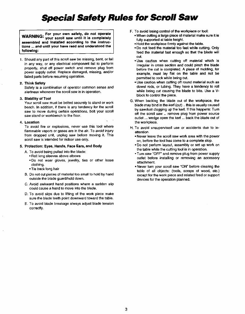
I. Should any part of this scroll saw be missing, bent, or fail in any way, or any electrical component fail to perform properly, shut off power switch and remove plug from power supply outlet. Replace damaged, missing, andor failed parts before resuming operation.
Safety is a combination of operator common sense and alertness whenever the scroll saw is in operation.
Your scroll saw must be bolted securely to stand or work bench. In addition, if there is any tendency for the scroll saw to move during certain operations, bolt your scroll saw stand or workbench to the floor.
To avoid fire or explosions, never use this tool where flammable vapors or gases are in the air. To avoid injury from dropped unit, unplug saw before moving it. This scroll saw is intended for indoor use only.
2. Think Safety
3. Stability of Tool
4. Location
5. Protection: Eyes, Hands, Face Ears, and Body A. To avoid being pulled into the blade:
Roll long sleeves above elbows *Do not wear gloves, jewelry, ties or other loose
Tie back long hair 6. Do not cut pieces of material too small to hold by hand
outside the blade guard/hold down. C. Avoid awkward hand positions where a sudden slip
could cause a hand to move into the blade. D. To avoid slips due to lifting of the work piece make
sure the blade teeth point downward toward the table. E. To avoid blade breakage always adjust blade tension
correctly.
clothing.
F. To avoid losing control of the workpiece or tool: When cutting a large piece of material make sure it is
Hold the workpiece firmly against the table. Do not feed the material too fast while cutting. Only feed the material fast enough so that the blade will cut.
*Use caution when cutting off material which is irregular in cross section and could pinch the blade before the cut is completed. A piece of molding, for example, must lay flat on the table and not be permitted to rock while being cut. Use caution when cutting off round material such as dowel rods, or tubing. They have a tendency to roll while being cut causing the blade to bite. Use a V- block to control the piece.
G. When backing the blade out of the workpiece, the blade may bind in the kerf (cut) .. this is usually caused by sawdust clogging up the kerf. If this happens: Turn off the scroll saw .. remove plug from power source outlet ... wedge open the kerf ... back the blade out of the workpiece.
H. To avoid unsupervised use or accidents due to in- attention.
Never leave the scroll saw work area with the power on, before the tool has come to a complete stop.
*Do not perform layout, assembly or set up work on the table while the cutting tool is in operation.
*Turn saw "OFF" and remove plug from power supply outlet before installing or removing an accessory attachment. Never turn your scroll saw "ON" before clearing the table of all objects: (tools, scraps of wood, etc.) except for the work piece and related feed or support devices for the operation planned.
fully supported at table height.
3
Motor Specifications and Electrical Requirements
This tool is designed to use, and is wired for operation on 120 volts, 60 Hz., altemating current. (TOOL MUST NOT BE CONVERTED TO OPERATE ON 230 VOLT)
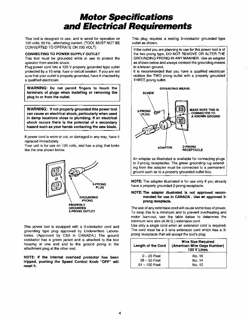
CONNECTING TO POWER SUPPLY OUTLET This tool must be grounded while in use to protect the operator from electric shock. Plug power cord into a 120 V properly grounded type outlet protected by a 15-amp. fuse or circuit breaker. If you are not sure that your outlet is properly grounded, have it checked by a qualified electrician.
WARNING: Do not permit fingers to touch the terminals of plugs when installing or removing the plug to or from the outlet.
WARNING: If not properly grounded this power tool can cause an electrical shock, particularly when used in damp locations close to plumbing. If an electrical shock occurs there is the potential of a secondary
If power cord is worn or cut, or damaged in any way, have it replaced immediately. Your unit is for use on 120 volts, and has a plug that looks like the one shown below.
GROUNDING PRONG
PROPERLY GROUNDED 3-PRONG OUTLET
This power tool is equipped with a 3-conductor cord and grounding type plug approved by Underwriters Labora- tories. (Approved by CSA in CANADA.) The ground conductor has a green jacket and is attached to the tool housing at one end and to the ground prong in the attachment plug at the other end.
NOTE: If the internal overload protector has been tripped, pushing the Speed Control Knob “OFF” will reset it.
This plug requires a mating 3-conductor grounded type outlet as shown.
If the outlet you are planning to use for this power tool is of the two prong type, DO NOT REMOVE OR ALTER THE GROUNDING PRONG IN ANY MANNER. Use an adapter as shown below and always connect the grounding means to a known ground. It is recommended that you have a qualified electrician replace the TWO prong outlet with a properly grounded THREE prong outlet.
GROUNDING MEANS
SCREW I
3-PRONG MAKE SURE THIS IS - CONNECTED TO A KNOWN GROUND
I ADAPTER 2-PRONG
RECEPTACLE
An adapter as illustrated is available for connecting plugs to 2-prong receptacles. The green grounding lug extend- ing from the adapter must be connected to a permanent ground such as to a properly grounded outlet box.
NOTE: The adapter illustrated is for use only if you already have a properly grounded 2-prong receptacle.
NOTE: The adapter illustrated is not approved recom- mended for use in CANADA . Use an approved 3- prong receptacle.
The use of any extension cord will cause some loss of power. To keep this to a minimum and to prevent overheating and motor burn-out, use the table below to determine the minimum wire size (A.W.G.) extension cord. Use only a single cord when an extension cord is required. The cord must be a 3 wire extension cord which has a 3- prong receptacle that will accept the tool’s plug.
I Length of the Cord
0 - 25 Feet 26 - 50 Feet
51 - 100 Feet
(American Wire Gage Number) 120 V Lines
No. 16 No. 14 No. 12
4
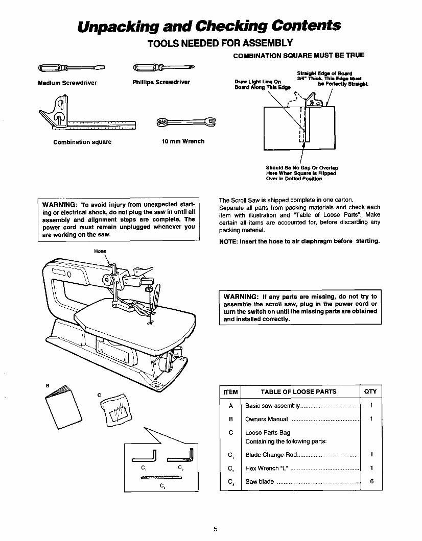
Unpacking and Checking Contents
TABLE OF LOOSE PARTS
Basic saw assembly ...................................
Owners Manual .........................................
Loose Parts Bag Containing the following parts:
Blade Change Rod .....................................
Hex Wrench "L" .........................................
Saw blade .................................................
TOOLS NEEDED FOR ASSEMBLY
QTY
1
1
1
1
6
COMBINATION SQUARE MUST BE TRUE
Straight E- d BoWd - -
W4" mi , This E* Mu.( k PertuAy S t n m t .
Medium Screwdriver Phillips Screwdriver Draw Light Line On Board Along This Edge I
Combination square 10 mm Wrench LJ.
WARNING: To avoid injury from unexpected start- ing or electrical shock, do not plug the saw in until all assembly and alignment steps are complete. The power cord must remain unplugged whenever you are working on the saw.
Hose
- - In 111
Should Be No'Gap Or Overlap Here When Square Is Flipped Over In Dotted Position
The Scroll Saw is shipped complete in one carton. Separate all parts from packing materials and check each item with illustration and 'Table of Loose Parts". Make certain all items are accounted for, before discarding any packing material.
NOTE: Insert the hose to air diaphragm before starting.
assemble the scroll saw, plug in the power cord or turn the switch on until the missing parts are obtained and installed correctlv.
5
Getting To Know Your Scroll Saw
Base 7. Table Lock Knob
&2& 9. Speed Control I On-Off Knob
\ Lamp support
5. Hold Down Foot Blade Tension Lever
11. Blade Support & Guard
2. Sawdust Blower
. Hold Down Foot
3. Sawdust Ejection Port
1. Blade Storage Case
6
Getting To Know Your Scroll Saw
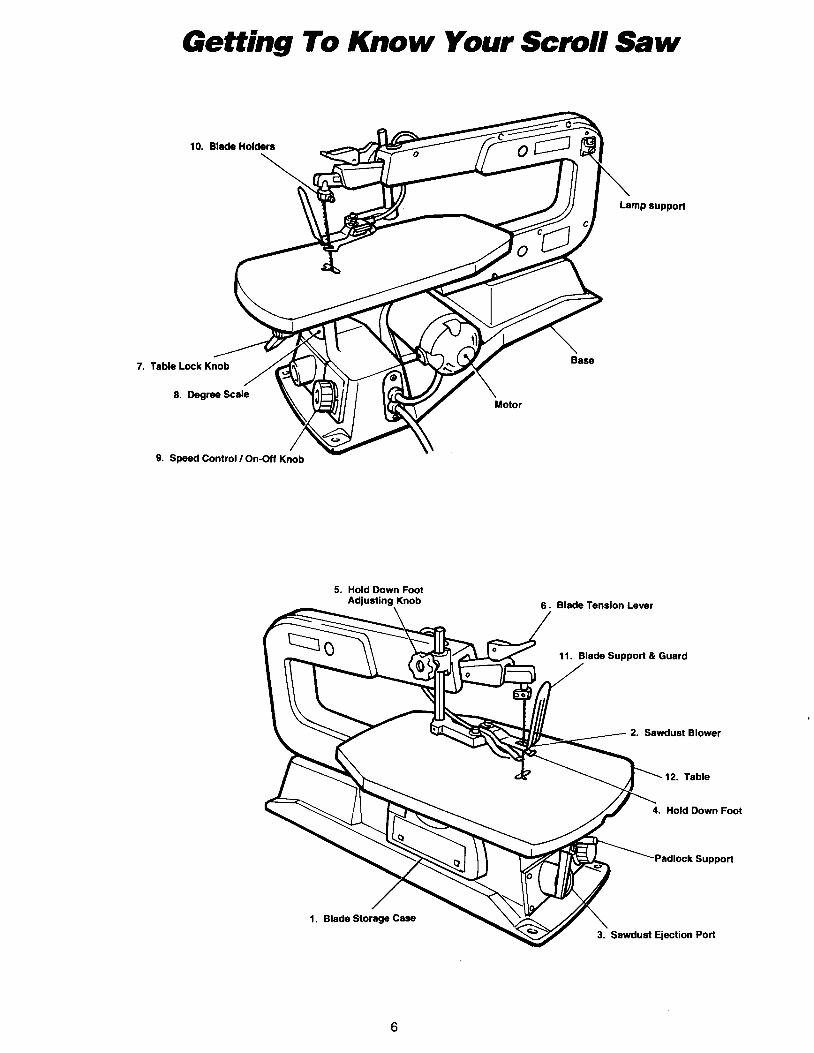
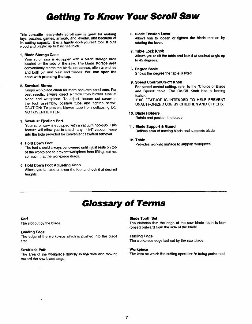
This versatile heavy-duty scroll saw is great for making toys, puzzles, games, artwork, and jewelry, and because of its cutting capacity, it is a handy do-it-yourself tool. It cuts wood and plastic up to 2 inches thick.
1. Blade Storage Case Your scroll saw is equipped with a blade storage area located on the side of the saw. The blade storage area conveniently stores the blade set screws, allen wrenches and both pin and plain end blades. You can open the case with pressing the top.
2. Sawdust Blower Keeps workpiece clean for more accurate scroll cuts. For best results, always direct air flow from blower tube at blade and workpiece. To adjust, loosen set screw in the foot assembly, position tube and tighten screw. CAUTION: To prevent blower tube from collapsing DO NOT OVERTIGHTEN.
3. Sawdust Ejection Port Your scroll saw is equipped with a vacuum hook-up. This feature will allow you to attach any 1-1/4" vacuum hose into the hole provided for convenient sawdust removal.
4. Hold Down Foot The foot should always be lowered until it just rests on top of the workpiece to prevent workpiece from lifting, but not so much that the workpiece drags.
5. Hold Down Foot Adjusting Knob Allows you to raise or lower the foot and lock it at desired heights.
6. Blade Tension Lever Allows you to loosen or tighten the blade tension by rotating the lever.
7. Table Lock Knob Allows you to tilt the table and lock it at desired angle up to 45 degrees.
8. Degree Scale Shows the degree the table is tilted.
9. Speed ControWOn-off Knob For speed control setting, refer to the "Choice of Blade and Speed" table. The On-Off Knob has a locking feature. THIS FEATURE IS INTENDED TO HELP PREVENT UNAUTHORIZED USE BY CHILDREN AND OTHERS.
10. Blade Holders Retain and position the blade
11. Blade Support 4% Guard Defines area of moving blade and supports blade
12. Table Provides working surface to support workpiece.
Glossary of Tenns Kerf Blade Tooth Set The slot cut by the blade.
Leading Edge The edge of the workpiece which is pushed into the blade first.
The distance that the edge of the saw blade tooth is bent (onset) outward from the side of the blade.
Trailing Edge The workpiece edge last cut by the saw blade.
Sawblade Path Workpiece The area of the workpiece directly in line with and moving toward the saw blade edge.
The item on which the cutting operation is being performed.
7
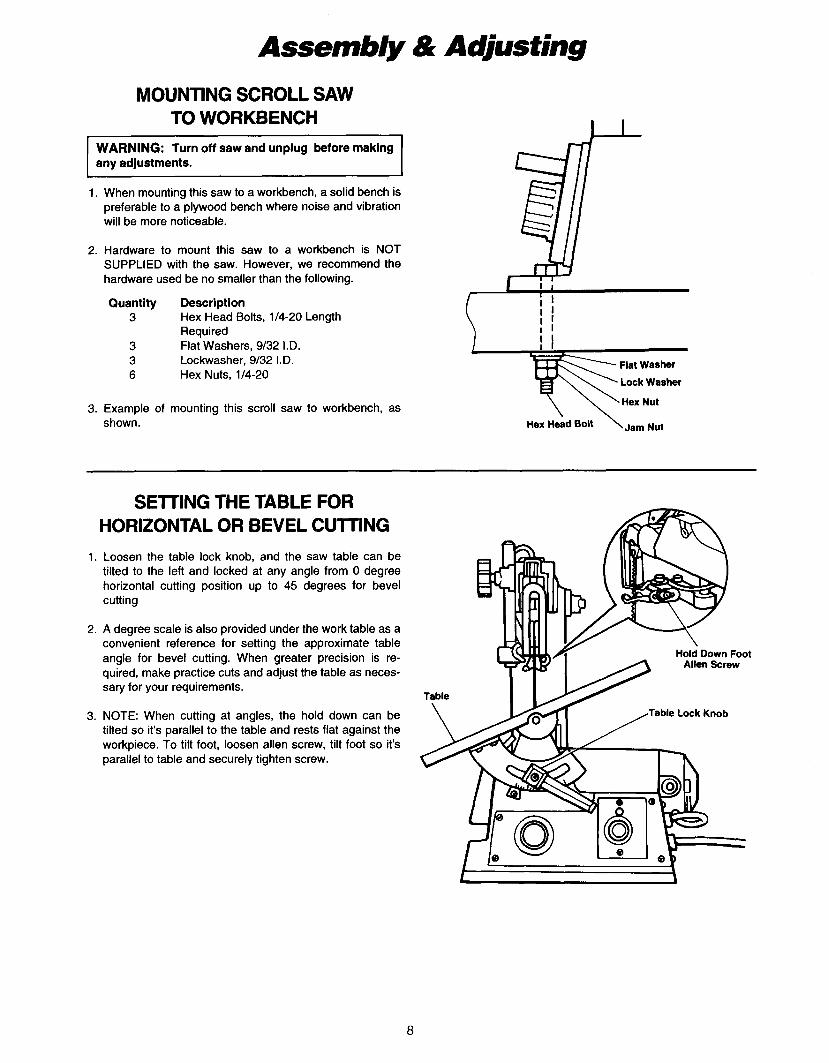
Assembly & Adjusting MOUNTING SCROLL SAW
TO WORKBENCH
I WARNING: Turn off saw and unplug before making any adjustments.
When mounting this saw to a workbench, a solid bench is preferable to a plywood bench where noise and vibration will be more noticeable.
Hardware to mount this saw to a workbench is NOT SUPPLIED with the saw. However, we recommend the hardware used be no smaller than the following. I 1 r I I
Quantity Description ; I 3 Hex Head Bolts, 1/4-20 Length ; I
Required I 1
3 Flat Washers, 9/32 I.D. ! I 3 Lockwasher, 9/32 I.D. 6 Hex Nuts, 1/4-20
Example of mounting this scroll saw to workbench, as shown.
SETING THE TABLE FOR HORIZONTAL OR BEVEL CUlTlNG
1. Loosen the table lock knob, and the saw table can be tilted to the left and locked at any angle from 0 degree horizontal cutting position up to 45 degrees for bevel cutting
2. A degree scale is also provided under the work table as a convenient reference for setting the approximate table angle for bevel cutting. When greater precision is re- quired, make practice cuts and adjust the table as neces- sary for your requirements.
3. NOTE: When cutting at angles, the hold down can be tilted so it's parallel to the table and rests flat against the workpiece. To tilt foot, loosen allen screw, tilt foot so it's parallel to table and securely tighten screw.
a
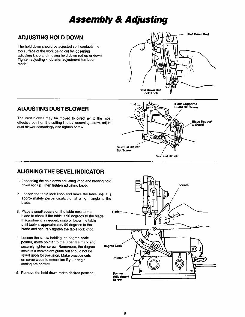
Assembly dk Adjusting
ADJUSTING HOLD DOWN The hold down should be adjusted so it contacts the top surface of the work being cut by loosening adjusting knob and moving hold down rod up or down. Tighten adjusting knob after adjustment has been made.
Hold Down Rod Lock Knob
ADJUSTING DUST BLOWER The dust blower may be moved to direct air to the most effective point on the cutting line by loosening screw, adjust dust blower accordingly and tighten screw.
Blade support & Guard Set Screw
Blade support & Guard
Sawdust Blower Set Screw
Sawdust Blower
ALIGNING THE BEVEL INDICATOR 1. Loosening the hold down adjusting knob and moving hold
down rod up. Then tighten adjusting knob.
2. Loosen the table lock knob and move the table until it is approximately perpendicular, or at a right angle to the blade.
3. Place a small square on the table next to the blade to check if the table is 90 degrees to the blade. If adjustment is needed, raise or lower the table until table is approximately 90 degrees to the blade and securely tighten the table lock knob.
4. Loosen the screw holding the degree scale pointer, move pointer to the 0 degree mark and securely tighten screw. Remember, the degree scale is a convenient guide but should not be relied upon for precision. Make practice cuts on scrap wood to determine if your angle setting are correct.
DWrm
5. Remove the hold down rod to desired position.
9
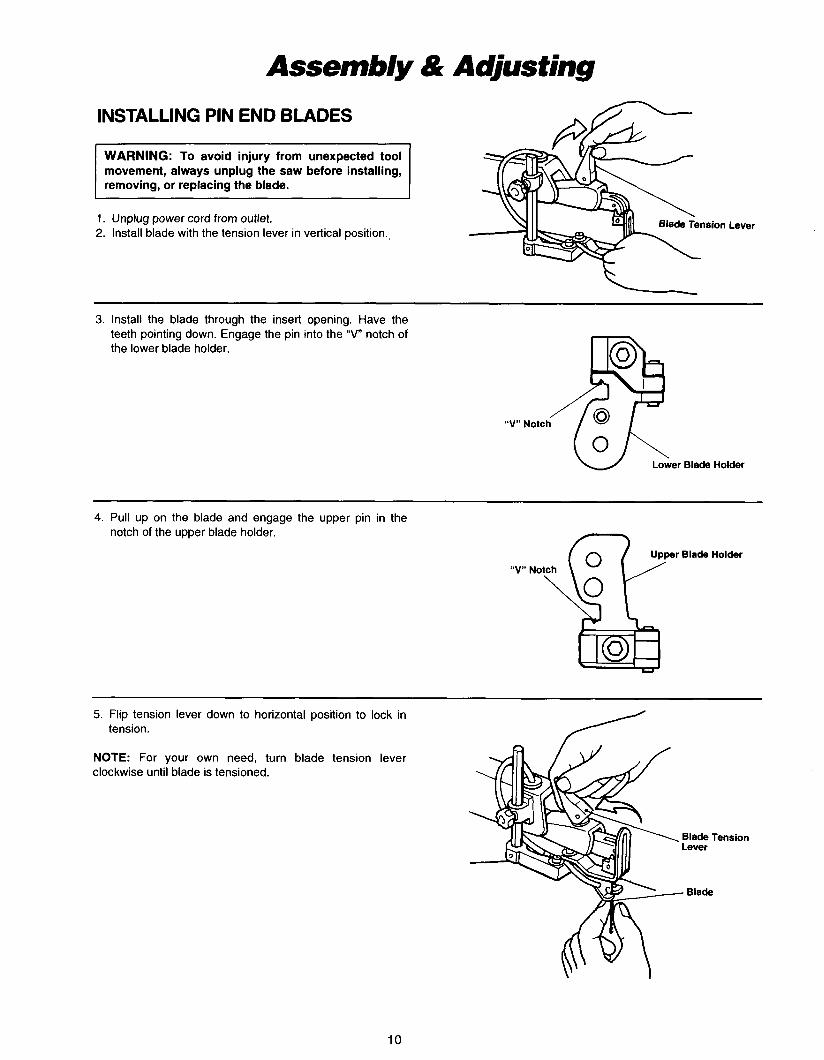
Assemb/y & Adjusting INSTALLING PIN END BLADES
WARNING: To avoid injury from unexpected tool movement, always unplug the saw before installing, removing, or replacing the blade.
1 . Unplug power cord from outlet. 2. Install blade with the tension lever in vertical position.,
Lever
3. Install the blade through the insert opening. Have the teeth pointing down. Engage the pin into the "V" notch of the lower blade holder.
w Lower Blade Holder
4. Pull up on the blade and engage the upper pin in the notch of the upper blade holder.
Blade Holder
5. Flip tension lever down to horizontal position to lock in tension.
NOTE: For your own need, turn blade tension lever clockwise until blade is tensioned.
10
Assembly & Aausting
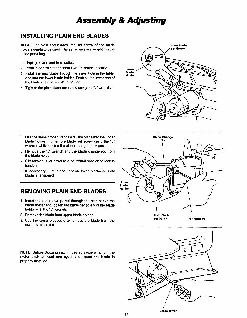
INSTALLING PLAIN END BLADES NOTE: For plain end blades, the set screw of the blade holders needs to be used. The set screws are supplied in the loose parts bag.
1. Unplug power cord from outlet. 2. Install blade with the tension lever in vertical position. 3. Install the new blade through the insert hole in the table,
and into the lower blade holder. Position the lower end of the blade in the lower blade holder.
4. Tighten the plain blade set screw using the “L” wrench.
5. Use the same procedure to install the blade into the upper blade holder. Tighten the blade set screw using the “L” wrench, while holding the blade change rod in position.
6. Remove the ‘I“ wrench and the blade change rod from the blade holder.
7. Flip tension lever down to a horizontal position to lock in tension.
8. If necessary, turn blade tension lever clockwise until blade is tensioned.
REMOVING PLAIN END BLADES 1. Insert the blade change rod through the hole above the
blade holder and loosen the blade set screw of the blade holder with the “L” wrench.
2. Remove the blade from upper blade holder 3. Use the same procedure to remove the blade from the
Plain Blade Set Screw “L” Wrench
lower blade holder.
NOTE: Before plugging saw in, use screwdriver to turn the motor shaft at least one cycle and insure the blade is properly installed.
Screwdriver 11
Assembly dk Adjusting
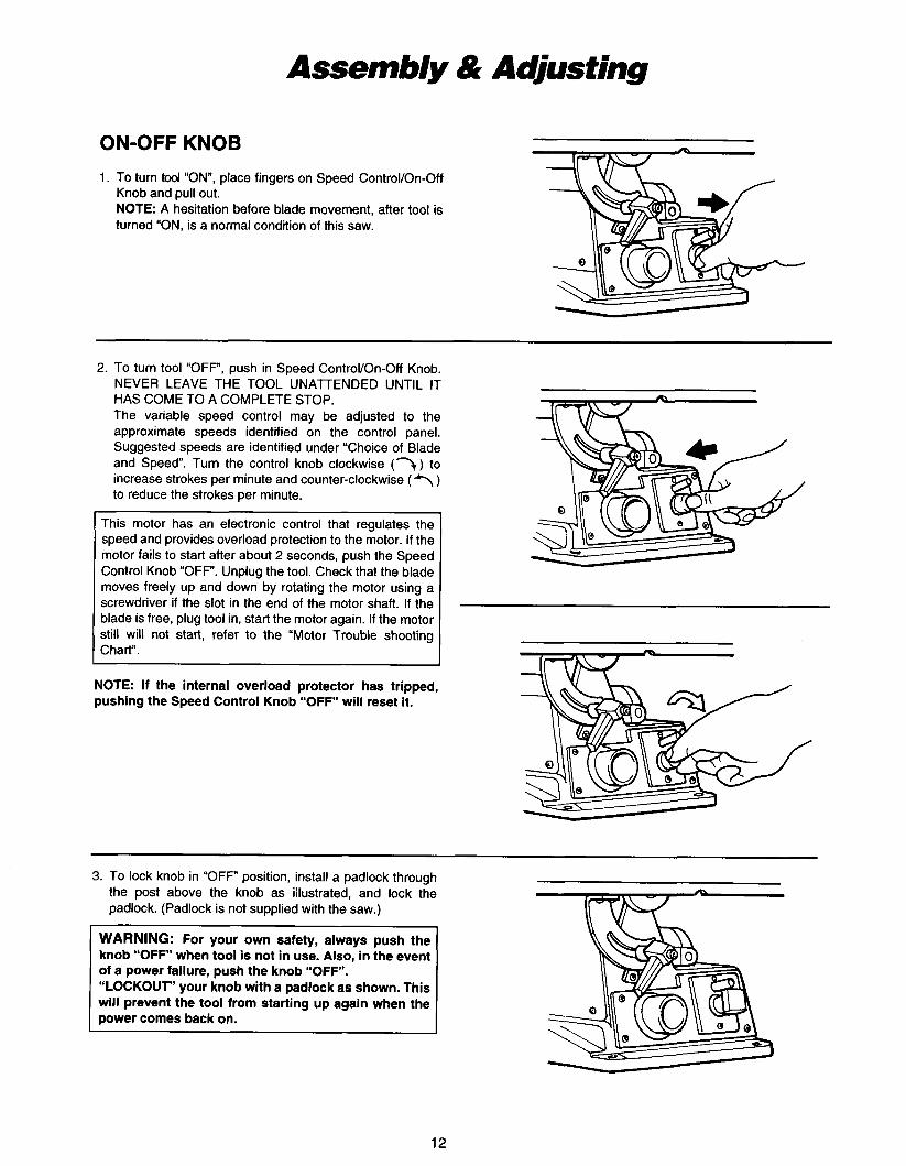
ON-OFF KNOB 1. To turn tool “ON”, place fingers on Speed ControVOn-Off
Knob and pull out. NOTE: A hesitation before blade movement, after tool is turned “ON, is a normal condition of this saw.
2. To turn tool “OFF”, push in Speed ControVOn-Off Knob. NEVER LEAVE THE TOOL UNAlTENDED UNTIL IT HAS COME TO A COMPLETE STOP. The variable speed control may be adjusted to the approximate speeds identified on the control panel. Suggested speeds are identified under “Choice of Blade and Speed. Turn the control knob clockwise (7) to increase strokes per minute and counter-clockwise (1 ) to reduce the strokes per minute.
This motor has an electronic control that regulates the speed and provides overload protection to the motor. If the motor fails to start after about 2 seconds, push the Speed Control Knob “OFF. Unplug the tool. Check that the blade moves freely up and down by rotating the motor using a screwdriver if the slot in the end of the motor shaft. If the blade is free, plug tool in, start the motor again. If the motor still will not start, refer to the “Motor Trouble shooting Chart”.
NOTE: If the internal overload protector has tripped, pushing the Speed Control Knob “OFF will reset it.
3. To lock knob in “OFF” position, install a padlock through the post above the knob as illustrated, and lock the padlock. (Padlock is not supplied with the saw.)
WARNING: For your own safety, always push the knob “OFF when tool is not in use. Also, in the event of a power failure, push the knob “OFF”. “LOCKOUT” your knob with a padlock as shown. This will prevent the tool from starting up again when the power comes back on.
12
Basic Scroll Saw Operation PLEASE, read and understand the following items about your scroll saw before attempting to use the saw.
1. Allow the saw to cut wood by guiding the wood into the blade as it moves.
2. The blade teeth cut wood ONLY on the down stroke.
3. You must guide the wood into the blade slowly because the teeth of the blade are very small and they can only remove wood on the down stroke.
4. There is a learning curve for each person who wants to use this saw. During that period of time, it is expected that some blades will break until you learn how to use the saw and receive the greatest benefit from the blades.
5. Best results are achieved when cutting wood less than one inch thick.
6. When cutting wood thicker than one inch, the user must guide the wood very, very slowly into the blade and take extra care not to bend or twist the blade while cutting.
7. Teeth on the scroll saw blades wear out and as such must be replaced frequently for best cutting results. Scroll saw blades generally stay sharp for 1/2 hour to 2 hours of cutting.
0. To get accurate cuts, be prepared to compensate for the blades' tendency to follow other wood grain as you are cutting.
9. This scroll saw is intended to cut wood or material similar to wood only.
10. When choosing a blade to use with your scroll saw, consider the following carefully.
Very fine, narrow blades should be used to scroll cut in thin wood 114" thick or less.
To cut wood over 1/4" thick, use wider blades.
Most blade packages state the size or thickness of wood which that blade is intended to cut, and the radius, size of curve, which can be cut with that blade.
Wider blades can't cut curves as tight or small as thinner blades.
Narrower blades work well only on thinner wood material.
11. This saw uses 5" long pin or plain end type blades.
12. Blades wear faster when cutting plywood, which is very abrasive; when sawing wood which is thicker than 314" blade stroke; and when sawing hardwood, or when side pressure is placed on the blade.
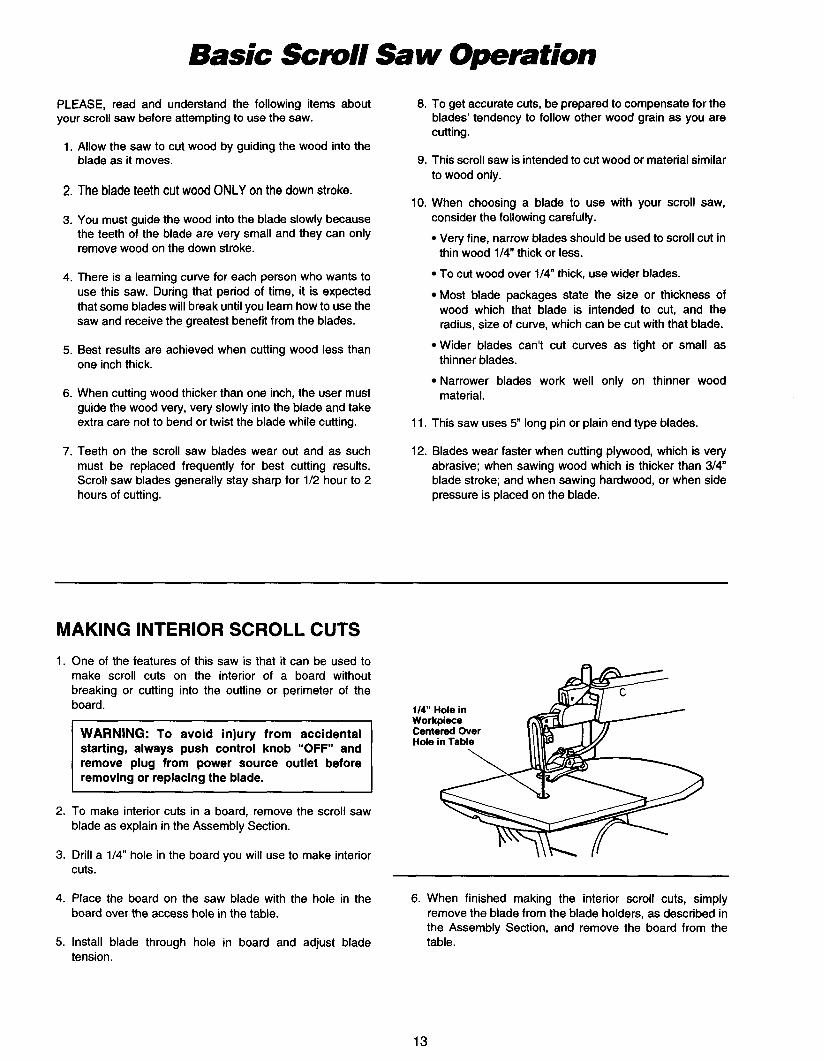
MAKING INTERIOR SCROLL CUTS 1. One of the features of this saw is that it can be used to
make scroll cuts on the interior of a board without breaking or cutting into the outline or perimeter of the board.
WARNING: To avoid injury from accidental starting, always push control knob "OFF" and remove plug from power source outlet before removing or replacing the blade.
2. To make interior cuts in a board, remove the scroll saw blade as explain in the Assembly Section.
3. Drill a 1 /4 hole in the board you will use to make interior cuts.
t14" Hole in
''''7\L //
4. Place the board on the saw blade with the hole in the board over the access hole in the table.
6. When finished making the interior scroll cuts, simply remove the blade from the blade holders, as described in the Assembly Section, and remove the board from the table. 5. Install blade through hole in board and adjust blade
tension.
13

BEFORE EACH USE:
Width
.I 1 0
.110
,095
Inspect your saw DISCONNECT THE SAW. To avoid injury from accidental starting, unplug the saw, push the switch "OFF" and lock the switch before changing the setup or removing covers, guards, or blade.
Inspect your workpiece Make sure there are no nails or foreign objects in the part of the workpiece to be cut.
Use extra caution with large, very small or awkward workpieces:
Never use this tool to cut pieces too small to hold by hand. Use extra supports (tables, saw horses, blocks, etc.) for any workpieces large enough to tip when not held down to the table top. NEVER use another person as a substitute for a table extension, or as additional support for a workpiece or to help feed, support or pull the workpiece. When cutting irregularly shaped workpieces, plan your work so it will not pinch the blade. A piece of molding, for example, must lay flat or be held by a fixture or jig that will not let it twist, rock or slip while being cut. Properly support round material such as dowel rods, or tubing. They have a tendency to roll during a cut, causing the blade to "bite". To avoid this, always use a " V block. Cut only one workpiece at a time. Clear everything except the workpiece and related support devices off the table before turning the saw on.
Thickness
.020
,020
.010
Plan the way you will hold the workpiece from start to finish Do not hand hold pieces so small that your fingers will go under the work hold-down. Use jigs or fixtures to hold the work and keep your hands away from the blade.
Before freeing any jammed material: Push switch "OFF". Lock the switch. Unplug the saw. Wait for all moving parts to stop.
When backing out the workpiece, the blade may bind in the kerf (cut). This is usually caused by sawdust clog- ging up the kerf. If this happens:
Push switch "OFF". Lock the switch. Unplug the saw. Wait for all moving parts to stop. Remove the blade from the blade holders. Remove workpiece with blade from the table. Remove blade from workpiece. Push switch "OFF".
Before removing loose pieces from the table, turn saw off and wait for all moving parts to stop.
CHOICE OF BLADE AND SPEED The scroll saw accepts a wide variety of blade widths and thicknesses. The blade width and thickness and the number
Teet hllnc h
10
15
18
Speed (StrokeslMin.)
C (1200- 1600)
B (600 - 1200)
A (400 - 600)
~
of teeth per inch are determined by the type of material and the size of the radius being cut. See the following chart.
Material Cut
Popular size for cutting hard and soft woods 3/16 up to 2" Also plastics, paper, felt, bone, etc.
Wood, plastic, extremely thin cuts on materials 3/32" to 1/2" thick.
For tight radius work in thin materials 3/32 to 1 / 8 wood veneer, wood, bone, fiber, ivory, plastic, etc.
As a general rule, always select the narrowest blades recommended for intricate curve cutting and widest blades for straight and large curve cutting operation.
14
Maintaining Your
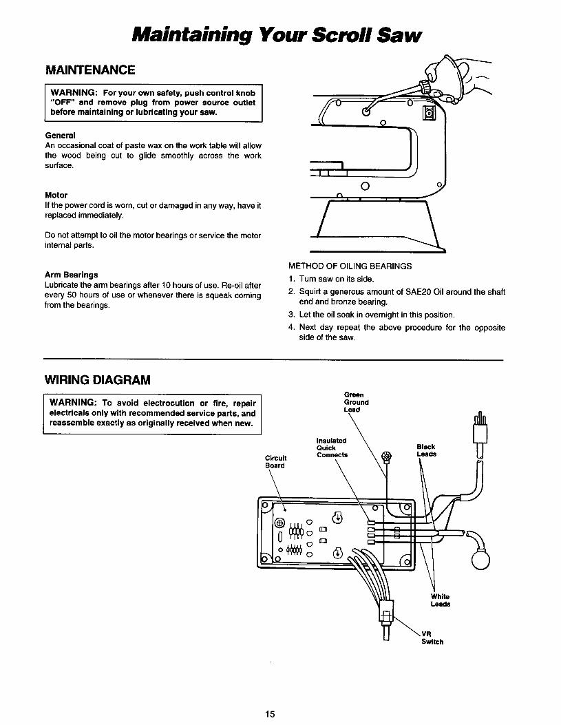
MAINTENANCE
WARNING: For your own safety, push control knob “OFF” and remove plug from power source outlet before maintaining or lubricating your saw.
General An occasional coat of paste wax on the work table will allow the wood being cut to glide smoothly across the work surface.
Motor If the power cord is worn, cut or damaged in any way, have it replaced immediately.
Do not attempt to oil the motor bearings or service the motor internal parts.
0 n
Arm Bearings Lubricate the arm bearings after 10 hours of use. Re-oil after every 50 hours of use or whenever there is squeak coming from the bearings.
METHOD OF OILING BEARINGS 1. Turn saw on its side. 2. Squirt a generous amount of SAE20 Oil around the shaft
3. Let the oil soak in overnight in this position. 4. Next day repeat the above procedure for the opposite
end and bronze bearing.
side of the saw.
WIRING DIAGRAM
15
Content Pants
16

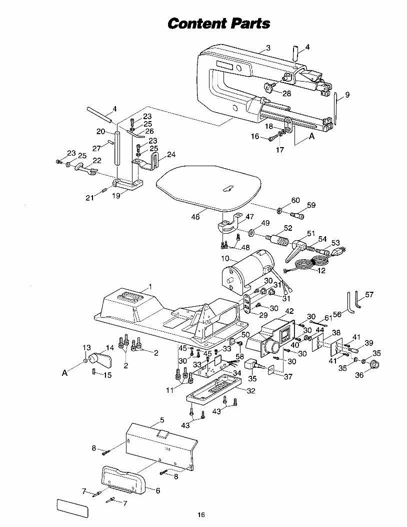
Part No.
1 2 3 4 5 6 7 8 9 10 1 1 12 13 14 15 16 17 18 19 20 21 22 23 24 25 26 27 28 29 30 31
Description
Base Screw and Washer (4) Body Hose Plate Cover Blade Storage Case Pull Nail (2) Screw (2) Blade Motor Screw and Washer (3) Power Cord Spacer Counterweight Set Screw Hex Socket Bolt Spring Washer Flat Washer Hold Down Block Support Rod Set Screw Hold Down Foot Hex Socket Bolt (3) Blade Support & Guard Flat Washer (3) Dust Blower Pin, Spring Knob Bushing Set Cover Screw (8) Bushing (2)
Part No.
32 33 34 35 36 37 38 39 40 41 42 43 44 45 46 47 48 49 50 51 52 53 54 56 57 58 59 60 61
Description
Board Cover Screw (2) Control Board Switch, Washer and Nut Control Knob Gasket Switch Cover Lock Post Nut Screw (2) Switch Case Screw (4) Ext. Tooth Washer Lock Washer (2) Table Tilt Bracket Screw (3) Flat Washer Pointer Bevel Lever Shaft Bolt Compressing Spring Blade Changing Rod Hex Wrench "L" Pan Head Screw Socket Head Screw Wave Washer Ground Wire
17
Content Parts
~~
Part No.
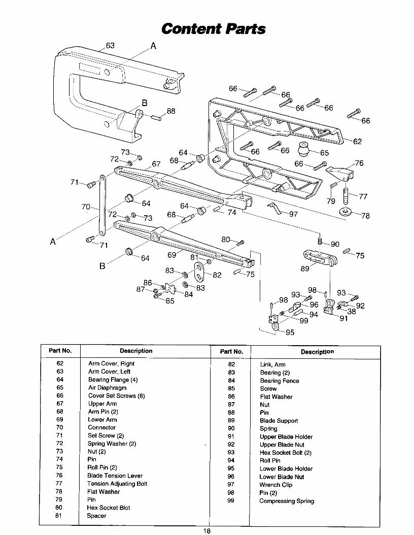
62 63 64 65 66 67 68 69 70 71 72 73 74 75 76 77 78 79 80 81
-85
Description
Arm Cover, Right Arm Cover, Left Bearing Flange (4) Air Diaphragm Cover Set Screws (8) Upper Arm Arm Pin (2) Lower Arm Connector Set Screw (2) Spring Washer (2) Nut (2) Pin Roll Pin (2) Blade Tension Lever Tension Adjusting Bolt Flat Washer Pin Hex Socket Blot Spacer
Part No.
82 83 84 85 86 87 88 89 90 91 92 93 94 95 96 97 98 99
98’8 93
38
95
Description
Link, Arm Bearing (2) Bearing Fence Screw Flat Washer Nut Pin Blade Support Spring Upper Blade Holder Upper Blade Nut Hex Socket Bolt (2) Roll Pin Lower Blade Holder Lower Blade Nut Wrench Clip Pin (2) Compressing Spring

Tmuble Shooting
Turn switch “OFF” and always remove plug from the power source before trouble shooting.
TROUBLE
Breaking blades
Motor will not run.
Vibration NOTE: There will always be some vibration present when the saw is running because of motor opera- tion.
~
PROBLEM
1. Wrong tension.
2. Over working blade.
3. Wrong blade application.
4. Twisting blade in wood.
5. Incorrect teeth per inch.
1. Defective cord or plug.
2. Defective motor.
3. Defective wire connections.
1. Improper mounting of saw.
2. Unsuitable mounting surface.
3. Loose table or table resting
4. Loose motor mounting.
against motor.
REMEDY
1. Adjust blade tension.
2. Reduce feed rate.
3. Use narrow blades for cutting thin wood, wide blades for thicker wood.
4. Avoid side pressure on blade.
5. Blade should have minimum 3 teeth in contact with workpiece.
1. Replace defective parts before using saw again.
2. Consult Service Center. Any attempt to repair this
3. HAZARD unless repair is done by a qualified service
motor may void warranty.
technician.
1. See “MOUNTING SCROLL SAW WORKBENCH”.
2. The heavier your work bench is, the less vibration will occur. A plywood workbench will not be as good a work surfaces the same size solid lumber workbench. Use common sense in choosing a mounting surface.
3. Tighten table lock knob.
4. Tighten motor mounting screws.
NOTE: Consult your local Service Center if for any reason your motor will not run.
19

MAKmA LIMED ONE YEAR WARRANTY Warranty Policy
Every Makita tool is thoroughly inspected and tested before leaving the factory. It is warranted to be free of defects from workmanship and materials for the period of ONE YEAR from the date of original purchase. Should any trouble develop during this one-year period, return the COMPLETE tool, freight prepaid, to one of Makita’s Factory or Authorized Service Centers. If inspection shows the trouble is caused by defective workmanship or material, Makita will repair (or at our option, replace) without charge.
This Warranty does not apply where: 0 repairs have been made or attempted by others: 0 repairs are required because of normal wear and tear : 0 The tool has been abused, misused or improperly maintained; 0 alterations have been made to the tool.
IN NO EVENT SHALL MAKITA BE LIABLE FOR ANY INDIRECT. INCIDENTAL OR CON- SEQUENTIAL DAMAGES FROM THE SALE OR USE OF THE PRODucf THISDISCLAIMER APPLIES BOTH DURING AND AFTER THE TERM OF THIS WARRANTY. MAKITA DISCLAIMS LIABILITY FOR ANY IMPLIED WARRANTIES, INCLUDING IMPLIED WARRANTIES OF “MERCHANTABILITY” AND “FITNESS FOR A SPECIFIC PURPOSE,” AFTER THE ONE-YEAR TERM OF THIS WARRANTY. This Warranty gives you specific legal rights, and you may also have other rights which vary from state to state. Some states do not allow the exclusion or limitation of incidental or consequential damages, so the above limitation or exclusion may not apply to you. Some states do not allow limitation on how long an implied warranty lasts, so the above limitation may not apply to you.
Makita Corporation