Embed Size (px)
Citation preview
Variable Power Controller – VPC-1 – Rev.0 11-Feb-2010 page 1
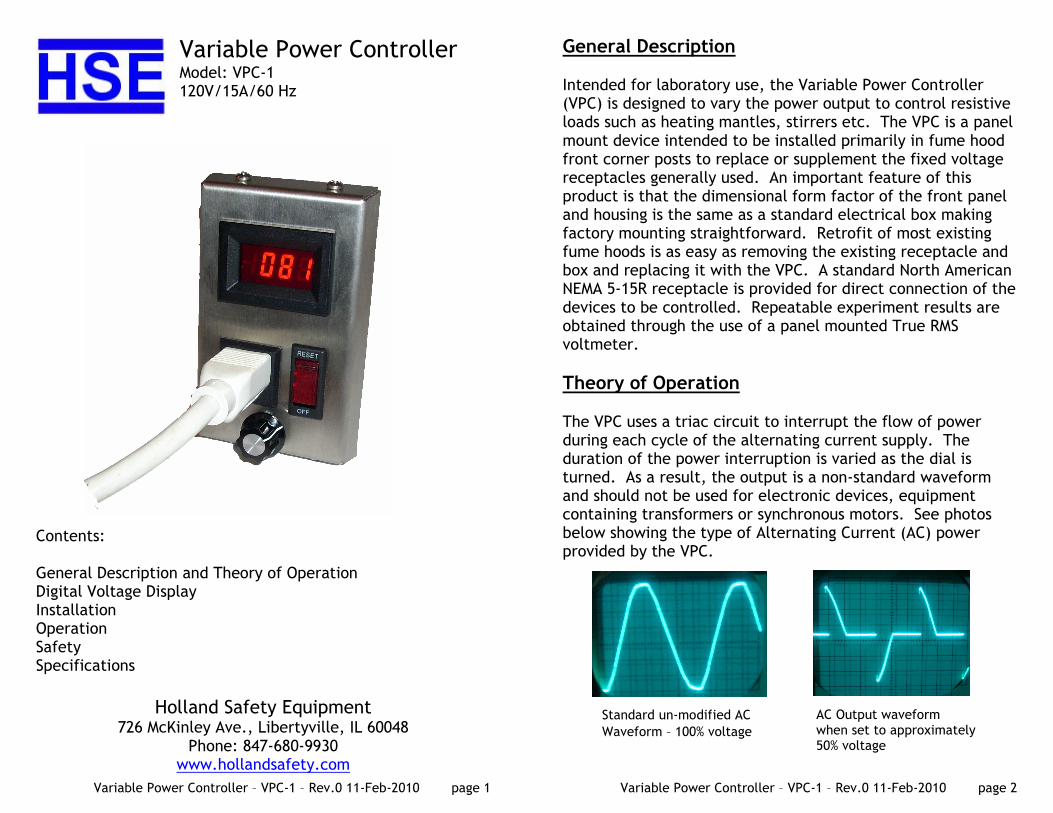
Variable Power Controller Model: VPC-1 120V/15A/60 Hz
Contents: General Description and Theory of Operation Digital Voltage Display Installation Operation Safety Specifications
Holland Safety Equipment 726 McKinley Ave., Libertyville, IL 60048
Phone: 847-680-9930 www.hollandsafety.com
Variable Power Controller – VPC-1 – Rev.0 11-Feb-2010 page 2
General Description Intended for laboratory use, the Variable Power Controller (VPC) is designed to vary the power output to control resistive loads such as heating mantles, stirrers etc. The VPC is a panel mount device intended to be installed primarily in fume hood front corner posts to replace or supplement the fixed voltage receptacles generally used. An important feature of this product is that the dimensional form factor of the front panel and housing is the same as a standard electrical box making factory mounting straightforward. Retrofit of most existing fume hoods is as easy as removing the existing receptacle and box and replacing it with the VPC. A standard North American NEMA 5-15R receptacle is provided for direct connection of the devices to be controlled. Repeatable experiment results are obtained through the use of a panel mounted True RMS voltmeter.
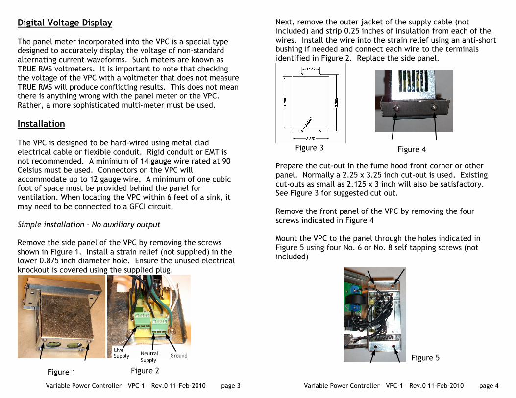
Theory of Operation The VPC uses a triac circuit to interrupt the flow of power during each cycle of the alternating current supply. The duration of the power interruption is varied as the dial is turned. As a result, the output is a non-standard waveform and should not be used for electronic devices, equipment containing transformers or synchronous motors. See photos below showing the type of Alternating Current (AC) power provided by the VPC.
Standard un-modified AC
Waveform – 100% voltage
AC Output waveform when set to approximately 50% voltage
Variable Power Controller – VPC-1 – Rev.0 11-Feb-2010 page 3
Digital Voltage Display The panel meter incorporated into the VPC is a special type designed to accurately display the voltage of non-standard alternating current waveforms. Such meters are known as TRUE RMS voltmeters. It is important to note that checking the voltage of the VPC with a voltmeter that does not measure TRUE RMS will produce conflicting results. This does not mean there is anything wrong with the panel meter or the VPC. Rather, a more sophisticated multi-meter must be used.
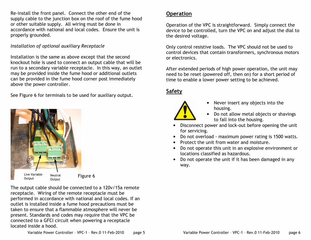
Installation The VPC is designed to be hard-wired using metal clad electrical cable or flexible conduit. Rigid conduit or EMT is not recommended. A minimum of 14 gauge wire rated at 90 Celsius must be used. Connectors on the VPC will accommodate up to 12 gauge wire. A minimum of one cubic foot of space must be provided behind the panel for ventilation. When locating the VPC within 6 feet of a sink, it may need to be connected to a GFCI circuit. Simple installation - No auxiliary output Remove the side panel of the VPC by removing the screws shown in Figure 1. Install a strain relief (not supplied) in the lower 0.875 inch diameter hole. Ensure the unused electrical knockout is covered using the supplied plug.
Figure 1 Figure 2
Neutral
Supply
Live Supply Ground
Variable Power Controller – VPC-1 – Rev.0 11-Feb-2010 page 4
Next, remove the outer jacket of the supply cable (not included) and strip 0.25 inches of insulation from each of the wires. Install the wire into the strain relief using an anti-short bushing if needed and connect each wire to the terminals identified in Figure 2. Replace the side panel.
Prepare the cut-out in the fume hood front corner or other panel. Normally a 2.25 x 3.25 inch cut-out is used. Existing cut-outs as small as 2.125 x 3 inch will also be satisfactory. See Figure 3 for suggested cut out. Remove the front panel of the VPC by removing the four screws indicated in Figure 4 Mount the VPC to the panel through the holes indicated in Figure 5 using four No. 6 or No. 8 self tapping screws (not included)
Figure 3 Figure 4
Figure 5
Variable Power Controller – VPC-1 – Rev.0 11-Feb-2010 page 5
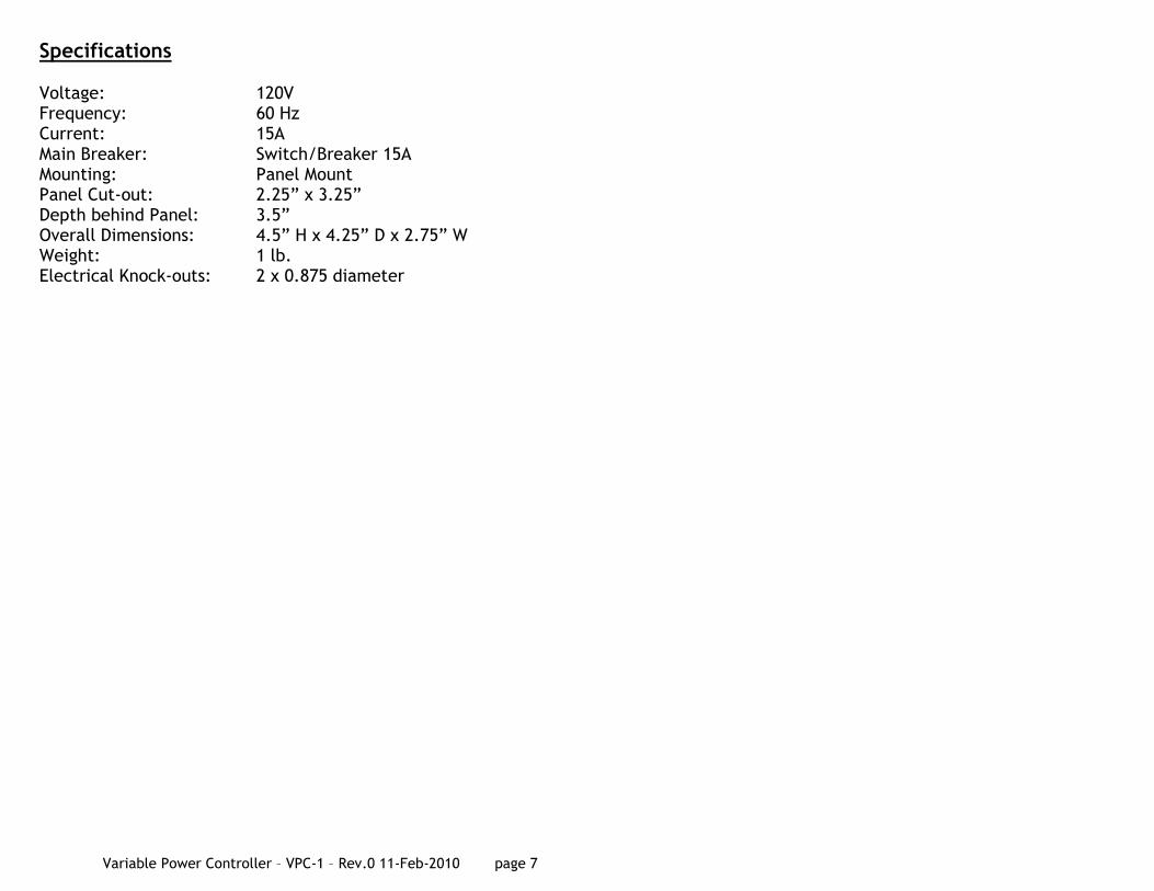
Re-install the front panel. Connect the other end of the supply cable to the junction box on the roof of the fume hood or other suitable supply. All wiring must be done in accordance with national and local codes. Ensure the unit is properly grounded. Installation of optional auxiliary Receptacle Installation is the same as above except that the second knockout hole is used to connect an output cable that will be run to a secondary variable receptacle. In this way, an outlet may be provided inside the fume hood or additional outlets can be provided in the fume hood corner post immediately above the power controller. See Figure 6 for terminals to be used for auxiliary output.
The output cable should be connected to a 120v/15a remote receptacle. Wiring of the remote receptacle must be performed in accordance with national and local codes. If an outlet is installed inside a fume hood precautions must be taken to ensure that a flammable atmosphere will never be present. Standards and codes may require that the VPC be connected to a GFCI circuit when powering a receptacle located inside a hood.
Live Variable
Output Neutral
Output Figure 6
Variable Power Controller – VPC-1 – Rev.0 11-Feb-2010 page 6
Operation Operation of the VPC is straightforward. Simply connect the device to be controlled, turn the VPC on and adjust the dial to the desired voltage. Only control resistive loads. The VPC should not be used to control devices that contain transformers, synchronous motors or electronics. After extended periods of high power operation, the unit may need to be reset (powered off, then on) for a short period of time to enable a lower power setting to be achieved.
Safety
• Never insert any objects into the housing.
• Do not allow metal objects or shavings to fall into the housing.
• Disconnect power and lock-out before opening the unit for servicing.
• Do not overload - maximum power rating is 1500 watts.
• Protect the unit from water and moisture.
• Do not operate this unit in an explosive environment or locations classified as hazardous.
• Do not operate the unit if it has been damaged in any way.
Variable Power Controller – VPC-1 – Rev.0 11-Feb-2010 page 7
Specifications Voltage: 120V Frequency: 60 Hz Current: 15A Main Breaker: Switch/Breaker 15A Mounting: Panel Mount Panel Cut-out: 2.25” x 3.25” Depth behind Panel: 3.5” Overall Dimensions: 4.5” H x 4.25” D x 2.75” W Weight: 1 lb. Electrical Knock-outs: 2 x 0.875 diameter