Embed Size (px)
Citation preview

TRAK Project No. S1700100 NEOGENOMICS
PDG Architects Issue For Construction
PDG Project No. 17001 July 17, 2017
Trak Engineering Inc. VARIABLE FREQUENCY DRIVES
1 of 10 SECTION 23 05 13
SECTION 23 05 13 – VARIABLE FREQUENCY DRIVES
PART 1 - GENERAL
1.01 RELATED DOCUMENTS
A. Drawings and general provisions of the Contract, including General and Supplementary
Conditions and Division 01 Specification Sections, apply to this Section.
B. Specifications throughout all Divisions of the Project Manual are directly applicable to this
Section, and this Section is directly applicable to them.
1.02 SUMMARY
A. Perform all Work required to provide and install a complete variable frequency motor drive
(VFD) consisting of a pulse width modulated (PWM) inverter designed for use on a standard
NEMA Design B induction motor.
B. The drive manufacturer shall supply the drive and all necessary controls as specified.
1.03 REFERENCE STANDARDS
A. The latest published edition of a reference shall be applicable to this Project unless identified
by a specific edition date.
B. All reference amendments adopted prior to the effective date of this Contract shall be
applicable to this Project.
C. All materials, installation and workmanship shall comply with the applicable requirements and
standards addressed within the following references:
1. IEEE 519-1992 Recommended Practices and Requirements for Harmonic Control in
Electrical Power Systems.
2. ANSI/UL Standard UL508C, Underwriter’s Laboratories.
3. ICS 7.0, AC Adjustable Speed Drives, National Electrical Manufacturer’s Association
(NEMA).
4. IEC 16800 Parts 1 and 2.
1.04 QUALITY ASSURANCE
A. Company specializing in manufacturing the products specified in this Section with minimum
three (3) years experience.
B. VFD and options shall be UL listed as a complete assembly. VFD’s that require the customer
to supply external fuses are not acceptable.
C. VFD and options shall be tested to ANSI/UL Standard 508 and listed by a nationally
recognized testing agency such as UL or ETL.
D. VFD and options shall comply with applicable requirements of the latest Standards of
ANSI/UL, IEEE, and the NEC.

TRAK Project No. S1700100 NEOGENOMICS
PDG Architects Issue For Construction
PDG Project No. 17001 July 17, 2017
Trak Engineering Inc. VARIABLE FREQUENCY DRIVES
2 of 10 SECTION 23 05 13
1.05 SUBMITTALS
A. Product Data:
1. Submit product data for components and accessories.
2. All VFD’s for this Project shall be supplied by one manufacturer.
3. Submit Shop Drawings indicating outline dimensions, enclosure construction, lifting and
supporting points, electrical one-line diagram, equipment electrical ratings, noise levels
(including driven equipment) and total harmonic distortion (voltage and current).
4. Manufacturer shall provide terminal block to terminal block wiring diagrams coordinated
with the Owner to provide a complete and functional operating system. Furnish detailed
Drawings showing construction, dimensions, wiring diagrams, and installation procedures
for Engineer’s approval.
B. Operation and Maintenance Data:
1. Submit manufacturer’s written installation instructions.
2. Submit training outline.
3. Furnish harmonic analysis verifying compliance with specified distortion levels.
4. Furnish a list of recommended spare parts.
1.06 DELIVERY, STORAGE AND HANDLING
A. Deliver, store, protect and handle products to the Project Site under provisions of Division 01
and Division 20.
B. Accept products on Site in factory-fabricated protective container with factory installed
shipping skids and lifting lugs. Inspect for damage.
C. Store in clean dry place and protect from weather and construction traffic. Handle carefully to
avoid damage to components, enclosures and finish.
1.07 EXTRA MATERIALS
A. Submit two insulated-handle tools designed for pulling fuses in accordance with ANSI/IEEE
C37.46.
B. Refer to Section 26 28 13 for fuse requirements.
1.08 WARRANTY
A. VFD shall be unconditionally warranted by the manufacturer for two (2) years from the date of
Substantial Completion, not to exceed 30 months from date of shipment.
B. Warranty shall include all parts, labor, shipping, field service or technician time, labor or travel
expenses, and verbal or written correspondence with the VFD manufacturer or VFD
manufacturer’s representatives. Include correspondence which might be incidental to the
proper installation and operation of the equipment.
TRAK Project No. S1700100 NEOGENOMICS
PDG Architects Issue For Construction
PDG Project No. 17001 July 17, 2017
Trak Engineering Inc. VARIABLE FREQUENCY DRIVES
3 of 10 SECTION 23 05 13
PART 2 - PRODUCTS
2.01 GENERAL
A. All materials shall meet or exceed all applicable referenced standards, federal, state and local
requirements, and conform to codes and ordinances of authorities having jurisdiction.
B. Furnish complete VFD controllers that convert incoming fixed frequency three-phase AC
power into a variable frequency and voltage for controlling the speed of three-phase AC
motors. The motor current shall closely approximate a sine wave. Motor voltage shall be
varied with frequency to maintain desired motor magnetization current suitable for centrifugal
pump and fan control and to eliminate the need for motor derating.
C. VFD must have a "bypass" switch as indicated in the Contract Documents, to allow the motor
to run if the controller malfunctions. All safety devices shall be energized. VFD manufacturer
shall verify compatibility of motor furnished on equipment with the product. One controller
shall control the speed of one motor only.
D. VFD shall convert 3 phase, 60 Hz utility power to adjustable voltage and frequency, 3 phase
AC power for stepless motor speed control from 10 percent to 100 percent of the motor’s 60
Hz speed. Input voltage characteristics are 480 volts, 3 phase, 60 Hz.
E. VFD shall include a converter section. The converter section shall convert fixed frequency
and voltage AC utility power to a variable DC voltage. VFD’s that use silicon controlled
rectifiers in the converter bridge shall also include 5 percent reactors. Isolation transformers
are not acceptable in lieu of line reactors.
F. VFD shall include an inverter section. The inverter section shall invert the variable DC voltage
into a PWM wave form; adjustable voltage and frequency output for stepless motor speed
control.
G. Individual or simultaneous operation of VFD’s shall not add more than 5 percent total
harmonic voltage distortion and no more than 5 percent total harmonic current distortion (per
IEEE 519-92) to the normal bus.
1. VFD manufacturer shall perform harmonic analysis based on the electrical one-line
diagram.
2. The VFD manufacturer shall provide calculations specific to this installation, showing total
harmonic voltage distortion is less than 5 percent.
3. Input line filters shall be sized and provided as required by the VFD manufacturer to
ensure compliance with IEEE Standard 519-92. All VFD’s shall include a minimum of 5
percent impedance reactors, no exceptions.
H. VFD shall include a coordinated AC transient protection system consisting of 4-120 joule
rated MOV’s (phase to phase and phase to ground), a capacitor clamp, and 5 percent
impedance reactors.
I. Alternate Harmonics Specification:
1. Input line reactors and DC Bus filtered chokes (factory installed and wired in the drive
enclosure) shall be provided to allow reliable operation on a typical commercial power
distribution system and to minimize harmonics reflected onto the input line.

TRAK Project No. S1700100 NEOGENOMICS
PDG Architects Issue For Construction
PDG Project No. 17001 July 17, 2017
Trak Engineering Inc. VARIABLE FREQUENCY DRIVES
4 of 10 SECTION 23 05 13
a. Shall not interfere with computer and other electronic systems in the building.
b. If not inherently protected, provide a suitable isolation transformer.
c. The system shall not produce spikes on the incoming line.
2. Any inverter that generates sufficient electrical line noise to interfere with operation of
sensitive building equipment shall be field modified or replaced by the inverter supplier at
no additional cost to the Owner.
J. EMI / RFI filters. All VFD’s shall include EMI/RFI filters. The onboard filters shall allow the
VFD assembly to be CE Marked and the VFD shall meet product Standard EN 61800-3 for
the First Environment restricted level.
K. Low voltage logic and 115V control circuits shall be electrically isolated from the power circuits.
Signal circuit common shall be grounded.
L. VFD shall include a power ride-through feature to allow continuous operation up to a three-cycle
line loss.
M. Two independently adjustable accel and decel ramps with 1 to 1800 seconds adjustable time
ramps. Extended time periods are also acceptable.
N. VFD shall have full function output current limit adjustable from 10 to 100 percent. At the factory
with compatible motor, provide at least three lock-out ranges (50 rpm maximum each), two of
which can be used to correct any run test problems.
O. Components shall be pretested and complete VFD shall have full burn-in under full load for a
minimum of 12 hours. Provide at least three lockout ranges (50 rpm maximum), two of which
can be used to correct run test problems.
P. Ambient noise generated by the VFD shall be limited to an amount equal to the system noise
level as designated by the latest ASHRAE noise level guidelines for such equipment at each
octave band. Noise level criteria at different octave bands and mid-frequencies shall be
furnished with the submittal data.
Q. VFD shall include a motor flux optimization circuit that will automatically reduce applied motor
voltage to the motor to optimize energy consumption and audible motor noise.
2.02 MANUFACTURERS
A. Danfoss Graham.
B. ABB.
C. Yaskawa Electric.
2.03 ENCLOSURE
A. VFD shall be enclosed in a UL Listed Type 12 enclosure. Enclosure shall be UL listed as a
plenum rated VFD. The VFD tolerated voltage window shall allow operation from a line of +30
percent nominal, and -35 percent nominal voltage as a minimum.

TRAK Project No. S1700100 NEOGENOMICS
PDG Architects Issue For Construction
PDG Project No. 17001 July 17, 2017
Trak Engineering Inc. VARIABLE FREQUENCY DRIVES
5 of 10 SECTION 23 05 13
B. Environmental operating conditions: 0 to 40 degrees C continuous. VFD’s that can operate
at 40 degrees C intermittently (during a 24-hour period) are not acceptable and must be
oversized. Altitude from 0 to 3300 feet above sea level, less than 95 percent humidity, non-
condensing. VFD’s without these ratings are not acceptable.
C. The following operator controls shall be located on the front of the enclosure:
1. Bypass Hand-Off-Auto.
2. Drive mode selector.
3. Bypass mode selector.
4. Bypass fault reset.
5. Provide the following indicating lights (LED type). In addition, provide test mode or push
to test feature:
a. Power-on (ready).
b. Run enable (safeties) open.
c. Drive mode select damper opening.
d. Bypass mode selected.
e. Drive running.
f. Bypass running.
g. Drive fault.
h. Bypass fault.
i. Bypass H-O-A mode.
j. Automatic transfer to bypass selected.
k. Safety open.
l. Damper opening.
m. Damper end-switch made.
6. Provide the following relay (form C) outputs from the bypass:
a. System started.
b. System running.
c. Bypass override enabled.
d. Drive fault.
e. Bypass fault (motor overload or underload - broken belt).

TRAK Project No. S1700100 NEOGENOMICS
PDG Architects Issue For Construction
PDG Project No. 17001 July 17, 2017
Trak Engineering Inc. VARIABLE FREQUENCY DRIVES
6 of 10 SECTION 23 05 13
f. Bypass H-O-A position.
D. Digital inputs for the system shall accept 24V or 115VAC (selectable).
E. Customer Interlock Terminal Strip: Provide a separate terminal strip for connection of freeze,
fire, smoke contacts, and external start command. All external safety interlocks shall remain
fully functional whether the system is in Hand, Auto, or Bypass modes (not functional in
fireman’s override 2). The remote start/stop contact shall operate in VFD and bypass modes.
F. Dedicated digital input that will transfer motor from VFD mode to bypass mode upon dry
contact closure for fireman’s override. Two modes of operation are required:
1. The first mode forces the motor to bypass operation and overrides both the VFD and
bypass H-O-A switches and forces the motor to operate across the line (test mode). The
system will only respond to the digital inputs and motor protections.
2. The second mode operates as the first, but will also defeat the overload and single-phase
protection for bypass and ignore all keypad and digital inputs to the system (run until
destruction).
G. Include a “run permissive circuit” that will provide a normally open contact whenever a run
command is provided (local or remote start command in VFD or bypass mode). The VFD
system (VFD or bypass) shall not operate the motor until it receives a dry contact closure from
a damper or valve end-switch. When the VFD system safety interlock (fire detector,
freezestat, high static pressure switch, etc) opens, the motor shall coast to a stop and the run
permissive contact shall open, closing the damper or valve.
H. Include Class 20 or 30 (selectable) electronic motor overload protection.
2.04 BYPASS
A. Furnish where indicated on the Drawings, a complete factory wired and tested bypass system
consisting of an output contactor and bypass contactor. Overload protection shall be provided
in both drive and bypass modes.
B. Bypass to be furnished, built, and mounted by the VFD manufacturer.
C. Provide an internal switch to select manual or automatic bypass.
D. Provide an adjustable current sensing circuit for the bypass to provide loss of load indication
(broken belt) when in the bypass mode.
E. Door interlocked, padlockable disconnect that will disconnect all input power from the drive
and all internally mounted options.
F. Fused VFD only disconnect (service switch). Fast acting fuses exclusive to the VFD – fast
acting fuses allow the VFD to disconnect from the line prior to clearing upstream branch
circuit protection, maintaining bypass capability. Bypass designs, which have no such fuses,
or that incorporate fuses common to both the VFD and the bypass will not be accepted. The
following contactor bypass schemes are not acceptable.
1. Door interlocked main input disconnect switch.
2. Power on light.
TRAK Project No. S1700100 NEOGENOMICS
PDG Architects Issue For Construction
PDG Project No. 17001 July 17, 2017
Trak Engineering Inc. VARIABLE FREQUENCY DRIVES
7 of 10 SECTION 23 05 13
3. “Drive-off-bypass” manual mode selector switch.
G. The bypass shall incorporate an internally sourced power supply and shall not require an
external power source.
2.05 DISPLAY / KEYPAD
A. All applicable operating values shall be capable of being displayed in engineering (user) units.
A minimum of three (3) operating values from the list below shall be capable of being
displayed at all times. The display shall be in complete English words (alpha-numeric codes
are not acceptable):
1. Output frequency.
2. Motor speed (RPM, percent, or engineering units).
3. Motor current.
4. Calculated motor torque.
5. Calculated motor power (kW).
6. DC bus voltage.
7. Output voltage.
B. Keypad shall include a backlit LCD display. The display shall be in complete English words for
programming and fault diagnostics (alpha-numeric codes are not acceptable). The keypad
shall use the following assistants:
1. Start-up assistants.
2. Parameter assistants.
3. Maintenance assistant.
4. Troubleshooting assistant.
C. VFD shall have the same customer interface, including digital display, and keypad, regardless
of horsepower rating. Keypad shall be removable, capable of remote mounting and shall
allow for uploading and downloading of parameter settings as an aid for start-up of multiple
VFD’s.
D. Keypad shall include Hand-Off-Auto selections and manual speed control. The drive shall
incorporate “bumpless transfer” of speed reference when switching between “Hand” and
“Auto” modes. There shall be fault reset and “Help” buttons on the keypad. The Help button
shall include “on-line” assistance for programming and troubleshooting.

TRAK Project No. S1700100 NEOGENOMICS
PDG Architects Issue For Construction
PDG Project No. 17001 July 17, 2017
Trak Engineering Inc. VARIABLE FREQUENCY DRIVES
8 of 10 SECTION 23 05 13
E. Provide a built-in time clock with battery back-up in the VFD keypad. The time clock shall be
used to date and time stamp faults and record operating parameters at the time of fault. If the
battery fails, the VFD shall automatically revert to hours of operation since initial power up.
The time clock shall also be programmable to control start/stop functions, constant speeds,
PID parameter sets and output relays. The VFD shall have a digital input that allows an
override to the time clock (when in the off mode) for a programmable time frame. There shall
be four (4) separate, independent timer functions that have both weekday and weekend
settings.
2.06 SERIAL COMMUNICATION
A. VFD shall have the capability of communicating with the building automation system (BAS) via
an RS-485 serial port.
B. VFD shall be provided with protocol information specific to the selected BAS Provider and
shall be pre-configured at the factory to provide automatic communications without the need
for field programming.
C. VFD shall continue to provide serial communications regardless of how inverter is being
controlled (“manual” mode via keypad, “automatic” mode via BAS, or “stopped” mode via
either keypad or automatic BAS start/stop signal).
D. Serial communications capabilities shall include, but not be limited to:
1. Run/stop control speed set adjustment.
2. Proportional/integral or PID control adjustments.
3. Current limit.
4. Accel/decel time adjustments.
E. VFD shall have the capability of allowing the BAS to monitor the following feedback signals:
1. Process variable.
2. Output speed/frequency.
3. Current.
4. Torque.
5. Power (kW).
6. Operating hours.
7. Kilowatt hours (kWh).
8. Relay outputs.
9. Diagnostic warning and fault information.
F. VFD shall allow the BAS to control the drive’s digital and analog outputs and monitor all drive
digital and analog inputs via the serial interface.

TRAK Project No. S1700100 NEOGENOMICS
PDG Architects Issue For Construction
PDG Project No. 17001 July 17, 2017
Trak Engineering Inc. VARIABLE FREQUENCY DRIVES
9 of 10 SECTION 23 05 13
G. VFD shall be capable of providing the BAS with status signals for bypass operation and
external safety trips via serial interface.
2.07 SYSTEM OPERATION
A. Selector switch in the "off" position: controller run circuit shall be open and the system shall
not operate.
B. Selector switch in the "manual" position: motor speed shall be controlled by the manual speed
potentiometer.
C. Selector switch in the "auto" position: operation shall be via input 0 to 10 VDC or 4-20 mA
signal with strategy output speed proportional to the input signal. If required into the controls
strategy, VFD manufacturer shall furnish a pressure transducer mounted in the drive
enclosure to convert a 3 to 15 psi pressure signal to a 0 to 10 VDC signal or 4-20 mA signal.
PART 3 - EXECUTION
3.01 PREPARATION
A. Verify that surfaces are ready to receive Work.
B. Verify that field measurements are as shown on Shop Drawings and as instructed by
manufacturer.
C. Verify that required utilities are available, in the proper location, and ready for use.
3.02 INSTALLATION
A. Installation shall meet or exceed all applicable federal, state and local requirements,
referenced standards and conform to codes and ordinances of authorities having jurisdiction.
B. All installation shall be in accordance with manufacturer’s published recommendations.
C. Power wiring shall be completed by the Electrical Contractor in accordance with the
recommendations of the VFD manufacturer as outlined in the installation manual.
3.03 TESTING
A. Manufacturer shall provide a factory trained technician to inspect, test and start-up the VFD and
associated equipment and place the VFD into operation.
B. A harmonic test verifying the distortion level shall be included as part of Start-up and
forwarded to the Owner. Any additional equipment, installation and equipment floor space
required to meet the distortion level as set forth in the Specification, shall be borne by the VFD
manufacturer.
3.04 TRAINING
A. Manufacturer shall provide for and present to the Owner, at no cost to the Owner, a training
and troubleshooting course at the Owner’s location. [Note to Engineer: Select one of the
following training levels per Project requirements.]

TRAK Project No. S1700100 NEOGENOMICS
PDG Architects Issue For Construction
PDG Project No. 17001 July 17, 2017
Trak Engineering Inc. VARIABLE FREQUENCY DRIVES
10 of 10 SECTION 23 05 13
1. [Provide one (1) hour orientation/start-up operation training for a minimum of two (2)
people.]
2. [Provide minimum two-day training, four (4) hours per day for up to twelve (12) people.
This course shall be classroom instruction complete with visual aids, documentation,
circuit diagrams and hands-on training. This course shall not be construed as a sales
meeting, but rather as a school to familiarize the Owner with the care, troubleshooting,
and servicing of the VFD.]
END OF SECTION 23 05 13
TRAK Project No. S1700100 NEOGENOMICS
PDG Architects Issue For Construction
PDG Project No. 17001 July 17, 2017
Trak Engineering Inc. CONTRACTOR COORDINATION WITH TESTING, ADJUSTING,
AND BALANCING
1 of 4 SECTION 23 05 90
SECTION 23 05 90 – CONTRACTOR COORDINATION WITH TESTING, ADJUSTING, AND
BALANCING
PART 1 - GENERAL
1.01 RELATED DOCUMENTS
A. Drawings and general provisions of the Contract, including General and Supplementary
Conditions and Division 01 Specification Sections, apply to this Section.
B. Specifications throughout all Divisions of the Project Manual are directly applicable to this
Section, and this Section is directly applicable to them.
1.02 SUMMARY
A. Perform all Work required to prepare the building HVAC systems for testing, adjusting, and
balancing (TAB) Work indicated by the Contract Documents, including the following:
1. Preparation of air systems for testing, adjusting and balancing.
2. Preparation of hydronic and steam systems for testing, adjusting and balancing.
3. Providing materials and labor to assist TAB Firm in meeting testing, adjusting and
balancing requirements.
B. Testing, adjusting and balancing of the air conditioning systems and related ancillary
equipment will be performed by a technically qualified TAB Firm. The preparation for and
corrections necessary for the testing, adjusting and balancing of these systems, as described
herein, are the responsibility of this Contractor.
C. Make any changes or replacements to the sheaves, belts, dampers, valves, etc. required for
correct balance as advised by the TAB Firm, at no additional cost to the Owner.
1.03 REFERENCE STANDARDS
A. The latest published edition of a reference shall be applicable to this Project unless identified
by a specific edition date.
B. All reference amendments adopted prior to the effective date of this Contract shall be
applicable to this Project.
C. All materials, installation and workmanship shall comply with the applicable requirements and
standards addressed within the following references:
1. AABC: National Standards for Testing and Balancing Heating, Ventilating and Air
Conditioning Systems.
2. AABC: Testing and Balancing Procedures.
3. ASHRAE HVAC Applications Chapter 37: Testing, Adjusting and Balancing.

TRAK Project No. S1700100 NEOGENOMICS
PDG Architects Issue For Construction
PDG Project No. 17001 July 17, 2017
Trak Engineering Inc. CONTRACTOR COORDINATION WITH TESTING, ADJUSTING,
AND BALANCING
2 of 4 SECTION 23 05 90
4. ANSI/ASHRAE Standard 111: Practices for Measurement, Testing, Adjusting and
Balancing of Buildings, Heating, Ventilation, Air Conditioning and Refrigeration Systems.
1.04 QUALITY ASSURANCE
A. Provide and coordinate the services of qualified, responsible Subcontractors, suppliers and
personnel as required to correct, repair, and/or replace any and all deficient items or
conditions found during the course of this project, including during the testing, adjusting and
balancing period.
B. In order that systems may be properly tested, adjusted, and balanced, the Contractor shall
operate systems at Contractor’s expense for the length of time necessary to properly verify
the systems’ completion and readiness for TAB.
C. Project Contract completion schedules shall allow for sufficient time to permit the completion
of TAB services prior to Owner occupancy. Allow adequate time for the testing and balancing
activities during the construction period and prior to Substantial Completion.
PART 2 - PRODUCTS
2.01 GENERAL
A. None used.
PART 3 - EXECUTION
3.01 PREPARATION
A. Contractor shall be responsible to prepare the building heating, ventilating, and air
conditioning systems ready for TAB when scheduled.
B. Operational readiness requires that construction status of the building will permit the closing
of doors, windows, ceilings installed, etc., to obtain simulated or projected operating
conditions.
C. Notification of System Readiness:
1. Upon completion of the system installation Work, the Contractor shall notify the Owner
and TAB Firm in writing, certifying that the Work has been accomplished and that the air
conditioning systems are in operational readiness for testing, adjusting, and balancing.
2. TAB Firm shall notify the Contractor of TAB Firm’s readiness for balancing.
3. Should the TAB Firm be notified as described above, and the TAB Work commenced and
the systems are found NOT to be in readiness or a dispute occurs as to the readiness of
the systems, the Contractor shall request an inspection be made by a duly appointed
representative of the Owner, Architect, TAB Firm and the Contractor. This inspection will
establish to the satisfaction of the represented parties whether or not the systems meet
the basic requirements for TAB services. Should the inspection reveal the TAB services
notification to have been premature, all cost of the inspection and wasted Work
accomplished by the TAB Firm shall be the responsibility of the Contractor.

TRAK Project No. S1700100 NEOGENOMICS
PDG Architects Issue For Construction
PDG Project No. 17001 July 17, 2017
Trak Engineering Inc. CONTRACTOR COORDINATION WITH TESTING, ADJUSTING,
AND BALANCING
3 of 4 SECTION 23 05 90
3.02 INSTALLATION
A. Installation shall meet or exceed all applicable federal, state and local requirements,
referenced standards and conform to codes and ordinances of authorities having jurisdiction.
B. All installation shall be in accordance with manufacturer’s published recommendations.
C. Allow sufficient time for the TAB Firm to perform TAB Firm’s Work within the Project
schedule. Complete installation Work by system or floor, whichever is the most efficient for
scheduling. Develop the Project schedule in close coordination with the TAB Firm.
D. The Drawings and Specifications indicate valves, dampers and miscellaneous adjustment
devices for the purpose of adjustment to obtain optimum operating conditions. Install these
devices in a manner that will leave the devices accessible and readily able to be adjusted.
Immediately correct any malfunction encountered that the TAB Firm reports so that the
balancing Work can proceed with minimal delay.
E. Contractor shall promptly correct deficiencies of materials and workmanship identified as
delaying completion of TAB Work.
3.03 SYSTEMS VERIFICATION
A. Air Distribution Systems:
1. Verify installation for conformity to the Contract Documents. All supply, return, and
exhaust ducts shall be terminated and pressure tested for leakage as required by the
Contract Documents.
2. All volume, smoke and fire/smoke dampers are properly located and functional. Dampers
serving requirements of minimum and maximum outside, return, and relief air shall provide
tight closure and full opening, smooth and free operation.
3. All supply, return, exhaust and transfer grilles, registers, diffusers and terminal devices are
installed and airflow at each device shall be verified.
4. Air handling systems, units and associated apparatus, such as heating and cooling coils,
filter sections, access doors, etc., shall be sealed or blanked-off to eliminate excessive
uncontrolled bypass or leakage of air.
5. All fans (supply, return and exhaust) operating and verified for freedom from vibration, with
proper fan rotation and belt tension. Heater elements in motor starters are of proper size
and rating. Record motor amperage and voltage on each phase at Start-up and running, and
verify they do not exceed nameplate ratings.
6. All single and/or double duct variable and constant volume terminal units ("mixing boxes")
shall be installed and functional (i.e. controls functioning).
7. Duct systems and air handling units and coils are clean and free of debris.
8. Air systems are pressure independent and can be tested by floor, riser, system, etc. but
once the all systems are installed, the total flows and system tracking will require final
testing, adjusting and balancing.
B. Water Circulating Systems for plumbing systems:

TRAK Project No. S1700100 NEOGENOMICS
PDG Architects Issue For Construction
PDG Project No. 17001 July 17, 2017
Trak Engineering Inc. CONTRACTOR COORDINATION WITH TESTING, ADJUSTING,
AND BALANCING
4 of 4 SECTION 23 05 90
1. Check and verify pump alignment and rotation.
2. Open all valves to their full open position, close bypass stop valves. Set mixing valves to
full-flow through systems components. After the system is flushed and checked for
proper operation, remove and clean all strainers. Repeat the operation until circulating
water is clean.
3. Record the amperage of each pump motor on each phase and voltage after reaching
rated speed. Readings shall not exceed nameplate rating.
4. Verify that the electrical heater elements are of the proper size and rating.
5. All water circulating systems shall be full and free of air. Expansion tanks shall be set for
proper water level and all air vents shall be installed at high points of systems and
operating freely. Systems shall be cleaned and flushed. Chemicals shall be added to
closed systems to treat piping and inhibit corrosion.
6. Check and set operating temperatures and other parameters of the heat exchangers and
control devices to the design requirements.
7. Installation and system verification of condenser water, hot water, and chilled water
systems must be 100 percent complete prior to balancing.
C. Building Automation System (BAS):
1. Verify that all control components are installed in accordance with the Contract
Documents and that all control components are functional, including all electrical
interlocks, damper sequences, air and water resets, fire and freeze stats, high and low
temperature thermostats, safeties, etc.
2. Verify that all controlling instruments are calibrated and set for design operating
conditions with the exception of room thermostats or sensors, which shall be calibrated at
the completion of TAB services with cooperation between the TAB Firm and BAS
Provider.
3. BAS Provider shall thoroughly check all controls, sensors, operators, sequences, etc.
before notifying the TAB Firm that the building automation system is operational. The
BAS Provider shall provide technical support, including technicians and necessary
computers, to the TAB Firm for a complete check of these systems.
4. BAS Provider shall assist the Contractor with functional performance testing and point-to-
point testing back to the main graphics.
5. BAS Provider, if requested by Owner, shall set-up controls on sample fan powered
terminal units at TAB Firm’s office.
END OF SECTION 23 05 90

TRAK Project No. S1700100 NEOGENOMICS
PDG Architects Issue For Construction
PDG Project No. 17001 July 17, 2017
Trak Engineering Inc. SYSTEM TESTING, ADJUSTING, AND BALANCING FOR HVAC
1 of 11 SECTION 23 05 93
SECTION 23 05 93 – SYSTEM TESTING, ADJUSTING, AND BALANCING FOR HVAC
PART 1 - GENERAL
1.01 RELATED DOCUMENTS
A. Drawings and general provisions of the Contract, including General and Supplementary
Conditions and Division 01 Specification Sections, apply to this Section.
B. Specifications throughout all Divisions of the Project Manual are directly applicable to this
Section, and this Section is directly applicable to them.
1.02 SUMMARY
A. Testing, adjusting, and balancing (TAB) of the air conditioning systems and related ancillary
equipment will be performed by a technically qualified TAB Firm (TAB Firm) selected and
employed by the Contractor as part of the Construction Contract.
B. TAB Firm shall be capable of performing the TAB services as specified in accordance with the
Contract Documents, including preparation and submittal of a detailed report of the actual
TAB Work performed.
C. TAB Firm shall check, adjust, and balance components of the air conditioning system which
will result in optimal noise, temperature, and airflow conditions in the conditioned spaces of
the building while the system equipment is operating economically and efficiently. This is
intended to be accomplished after the system components are installed and operating as
specified in the Contract Documents. It is the responsibility of the Contractor to place the
equipment into service. Variable air volume systems shall be balanced in accordance with
AABC Standard, Latest Edition or NEBB Standards for Testing, Adjusting, Balancing of
Environmental Systems (Latest Edition).
D. TAB Firm shall check, adjust, and balance all hydronic systems including pumps, water
distribution systems, chillers, cooling towers, boilers, heat exchangers, coils, and related
equipment.
E. Liaison and Early Field Inspection:
1. TAB Firm shall act as a liaison between the Owner, Architect and Contractor. TAB Firm
shall perform the following reviews (observations) and tests:
a. During construction, review all HVAC submittals such as control diagrams, air
handling devices, etc., that pertain to the ability to satisfactorily balance systems.
b. Test at least one or at least 10 percent of the single and fan-powered terminal units if
the number of units are greater then twenty (20), for casing and damper leakage
when the shipment arrives at the Project Site. All testing (except for the initial
terminal units) shall be performed at the Project Site.

TRAK Project No. S1700100 NEOGENOMICS
PDG Architects Issue For Construction
PDG Project No. 17001 July 17, 2017
Trak Engineering Inc. SYSTEM TESTING, ADJUSTING, AND BALANCING FOR HVAC
2 of 11 SECTION 23 05 93
c. Test one (1) lab configuration including fume hood with air valve, general exhaust air
with air valve and supply air with air valve for performance capability through a full
range of inlet pressures. The tracking capability of the exhaust air versus the supply
air will be with the submitted hood sash fully open and as the sash is closed in 2 inch
increments until fully closed. Track the valves’ response time in relation to sash
movement and the lab differential.
2. During the balancing process, as the TAB Firm discovers abnormalities and malfunctions
of equipment or components, the TAB Firm shall advise the Contractor in writing so that
the condition can be corrected by the Contractor prior to finishing the TAB scope of Work.
Data from malfunctioning equipment shall not be recorded in the final TAB report.
1.03 REFERENCE STANDARDS
A. The latest published edition of a reference shall be applicable to this Project unless identified
by a specific edition date.
B. All reference amendments adopted prior to the effective date of this Contract shall be
applicable to this Project.
C. All materials, installation and workmanship shall comply with the applicable requirements and
standards addressed within the following references:
1. AABC - National Standards for Testing and Balancing Heating, Ventilating, and Air
Conditioning Systems.
2. NEBB - National Environmental Balancing Bureau, Procedural Standards for Testing,
Adjusting, Balancing of Environmental Systems.
3. ASHRAE HVAC Applications Chapter 37: Testing, Adjusting and Balancing.
4. ANSI/ASHRAE Standard 111: Practices for Measurement, Testing, Adjusting and
Balancing of Buildings, Heating, Ventilation, Air Conditioning and Refrigeration Systems.
5. CTI - Cooling Technology Institute CODE ATC-105.
1.04 QUALITY ASSURANCE
A. TAB Firm shall have operated a minimum of five (5) years under TAB Firm’s current name
and shall be in good standing with the State of Texas, Franchise Tax Board. TAB Firm shall
submit full incorporated name, Charter Number, and Taxpayer's I.D. Number for proper
verification of TAB Firm's status.
B. TAB Firm’s personnel performing Work at the Project Site shall be either professional
engineers or certified air and water balance technicians, who shall have been permanent, full
time employees of the TAB Firm for a minimum of six (6) months prior to the start of Work for
this Project.
C. TAB firm shall have a background record of at least five (5) years of specialized experience in
the field of air and hydronic system balancing and shall possess properly calibrated
instrumentation.

TRAK Project No. S1700100 NEOGENOMICS
PDG Architects Issue For Construction
PDG Project No. 17001 July 17, 2017
Trak Engineering Inc. SYSTEM TESTING, ADJUSTING, AND BALANCING FOR HVAC
3 of 11 SECTION 23 05 93
1.05 SUBMITTALS
A. The activities described in this Section shall culminate in a report to be provided in
quadruplicate (4), individually bound and also provided electronically to the Contractor to be
presented to the Owner. Neatly type and arrange data. Include with the data, the dates
tested, personnel present, weather conditions, nameplate record of test instrument and list all
measurements taken after all corrections are made to the system. Record all failures and
corrective action taken to remedy incorrect situation. The intent of the report is to provide a
reference of actual operating conditions for the Owner's operations personnel.
B. All measurements and recorded readings (of air, water, electricity, etc.) that appear in the
report must have been made at the Project Site by the permanently employed technicians or
engineers of the TAB Firm.
C. At the Owner’s option, all data sheets tabulated each day by TAB Firm personnel shall be
submitted for review and sign-off by the Owner’s Construction Inspector. Those data sheets, as
initialed by Owner’s Construction Inspector, shall be presented as a supplement to the final TAB
report.
D. Submit reports on electronic forms approved by the Owner and Architect/Engineer which will
include the following information as a minimum:
1. Title Page:
a. Company name.
b. Company address.
c. Company telephone number.
d. Project name.
e. Project location.
f. Project Manager.
g. Project Engineer.
h. Project Contractor.
i. Project identification number.
2. Instrument List:
a. Instrument.
b. Manufacturer.
c. Model.
d. Serial number.
e. Range.
f. Calibration date.

TRAK Project No. S1700100 NEOGENOMICS
PDG Architects Issue For Construction
PDG Project No. 17001 July 17, 2017
Trak Engineering Inc. SYSTEM TESTING, ADJUSTING, AND BALANCING FOR HVAC
4 of 11 SECTION 23 05 93
g. What test instrument was used for.
3. Fan Data (Supply and Exhaust):
a. Identification and location.
b. Manufacturer.
c. Model.
d. Air flow, specified and actual.
e. Total static pressure (total external), specified and actual.
f. Inlet pressure.
g. Discharge pressure.
h. Fan RPM.
4. Air Handler Return Air/Outside Air Data (If fans are used, provide fan data as noted
above):
a. Identification and location.
b. Design return air flow.
c. Actual return air flow.
d. Design outside air flow.
e. Return air temperature.
f. Outside air temperature.
g. Required mixed air temperature.
h. Actual mixed air temperature.
5. Electric Motors:
a. Manufacturer.
b. Horsepower/brake horsepower.
c. Phase, voltage, amperage, nameplate, actual.
d. RPM.
e. Service factor.
f. Starter size, heater elements, rating.
6. V-Belt Drive:
a. Identification and location.

TRAK Project No. S1700100 NEOGENOMICS
PDG Architects Issue For Construction
PDG Project No. 17001 July 17, 2017
Trak Engineering Inc. SYSTEM TESTING, ADJUSTING, AND BALANCING FOR HVAC
5 of 11 SECTION 23 05 93
b. Required driven RPM.
c. Driven sheave, diameter and RPM.
d. Belt, size and quantity.
e. Motor sheave, diameter and RPM.
f. Center-to-center distance, maximum, minimum and actual.
7. Duct Traverse:
a. System zone/branch.
b. Duct size.
c. Area.
d. Design velocity.
e. Design air flow.
f. Test velocity.
g. Test air flow.
h. Duct static pressure.
i. Air temperature.
j. Air correction factor.
8. Air Monitoring Station Data:
a. Identification and location.
b. System.
c. Size.
d. Area.
e. Design velocity.
f. Design air flow.
g. Test velocity.
h. Test air flow.
9. Variable or Constant Volume Terminal Unit Test Sheet:
a. Identification number.
b. Room number/location.

TRAK Project No. S1700100 NEOGENOMICS
PDG Architects Issue For Construction
PDG Project No. 17001 July 17, 2017
Trak Engineering Inc. SYSTEM TESTING, ADJUSTING, AND BALANCING FOR HVAC
6 of 11 SECTION 23 05 93
c. Terminal type (FP if fan powered) and / or (SDVV, SDCV, DDVV, DDCV), and
(HWRH or ERH if reheat coil is used).
d. Terminal size.
e. Area factor.
f. Design velocity.
g. Design maximum and minimum air flow.
h. Test (final) velocity.
i. Test (final) maximum and minimum air flow.
j. For DDC instrumentation: Measure and record computer readout and calibration
factor at the final measurement conditions.
k. Air dry bulb temperature at the discharge of the terminal unit.
10. Pump Data for plumbing systems:
a. Identification and location.
b. Manufacturer.
c. Size/model.
d. Impeller size.
e. Service (RODI, HW, etc.).
f. Developed head pressure and BHP at design flow rate.
g. Developed head pressure and BHP at actual flow rate.
h. Pump discharge pressure.
i. Pump suction pressure.
j. Total operating head pressure at final balance.
k. Shut off, discharge and suction pressure.
l. Shut off, total head pressure.
m. Pressure differential settings.
n. Fluid temperature.
11. Cooling Coil Data:
a. Identification number.
b. Location.

TRAK Project No. S1700100 NEOGENOMICS
PDG Architects Issue For Construction
PDG Project No. 17001 July 17, 2017
Trak Engineering Inc. SYSTEM TESTING, ADJUSTING, AND BALANCING FOR HVAC
7 of 11 SECTION 23 05 93
c. Service.
d. Manufacturer.
e. Entering air DB temperature, design and actual.
f. Entering air WB temperature, design and actual.
g. Leaving air DB temperature, design and actual.
h. Leaving air WB temperature, design and actual.
i. Air quantity CFM design, and CFM actual.
j. Air pressure drop, design and actual.
k. Sensible Btu/hr design, and actual.
l. Total Btu/hr design, and actual.
12. Heating Coil Data (gas heat):
a. No balancing required.
13. Sound Level Report:
a. Location (Location established by the Engineer).
b. Baseline background NC curve for eight (8) bands – with equipment off.
c. Operating NC curve for eight (8) bands – with equipment on.
14. Vibration Test on equipment having 10 horsepower motors or greater:
a. Location of points:
1) Fan bearing, drive end.
2) Fan bearing, opposite end.
3) Motor bearing, center (if applicable).
4) Motor bearing, drive end.
5) Motor bearing, opposite end.
6) Casing (bottom or top).
7) Casing (side).
8) Duct after flexible connection (discharge outlet).
9) Duct after flexible connection (suction inlet).
b. Test readings:
1) Horizontal, velocity and displacement.

TRAK Project No. S1700100 NEOGENOMICS
PDG Architects Issue For Construction
PDG Project No. 17001 July 17, 2017
Trak Engineering Inc. SYSTEM TESTING, ADJUSTING, AND BALANCING FOR HVAC
8 of 11 SECTION 23 05 93
2) Vertical, velocity and displacement.
3) Axial, velocity and displacement.
c. Normally acceptable readings, velocity and acceleration.
d. Unusual conditions at time of test.
e. Vibration source (if non-complying).
15. Control verification indicating date performed and any abnormalities identified:
a. Point Location/Description.
b. EMS Readout (Setpoint and Actual).
c. Actual Readout.
d. Interlocks.
e. Safeties:
1) VSD Normal Operation.
2) VSD Bypass Operation.
f. Alarms.
g. Sequences of Operation.
16. Include in the appendix all submittals for air handling units, pumps, fans, heat
exchangers, energy recovery units control system, etc.
PART 2 - PRODUCTS
Not used.
PART 3 - EXECUTION
3.01 AIR BALANCE
A. When systems are installed and ready for operation, the TAB Firm shall perform an air
balance for all air systems and record the results. The outside, supply, exhaust and return air
volume for each air handling unit, supply fan and exhaust fan and the supply, exhaust or
return air volume for each distribution device shall be adjusted to within +/- 5 percent of the
value shown on the Drawings. Air handling unit and fan volumes shall be adjusted by
changing fan speed and adjusting volume dampers associated with the unit. Air distribution
device volume shall be adjusted using the spin-in tap damper for flexible duct connected
devices and the device opposed blade damper (OBD) for duct connected devices. Air
distribution devices shall be balanced with air patterns as specified. Duct volume dampers
shall be adjusted to provide air volume to branch ducts where such dampers are shown.
B. The general scope of balancing by the TAB Firm shall include, but is not limited to, the
following:

TRAK Project No. S1700100 NEOGENOMICS
PDG Architects Issue For Construction
PDG Project No. 17001 July 17, 2017
Trak Engineering Inc. SYSTEM TESTING, ADJUSTING, AND BALANCING FOR HVAC
9 of 11 SECTION 23 05 93
1. Filters: Check air filters and filter media and balance only systems with essentially clean
filters and filter media. The Contractor shall install new filters and filter media prior to the
final air balance.
2. Blower Speed: Measure RPM at each fan or blower to design requirements. Where a
speed adjustment is required, the Contractor shall make any required changes.
3. Ampere Readings: Measure and record full load amperes for motors.
4. Static Pressure: Static pressure gains or losses shall be measured across each supply
fan, cooling coil, heating coil, return air fan, air handling unit filter and exhaust fan. These
readings shall be measured and recorded for this report at the furthest air device or
terminal unit from the air handler supplying that device. Static pressure readings shall
also be provided for systems, which do not perform as designed.
5. Equipment Air Flow: Adjust and record exhaust, return, outside and supply air CFM(s)
and temperatures, as applicable, at each fan, blower and coil.
6. Coil Temperatures: Set controls for full cooling and for full heating loads. Read and
record entering and leaving dry bulb and wet bulb temperatures (cooling only) at each
cooling coil, heating coil and reheat coil at each VAV terminal unit. At the time of reading
record water flow and entering and leaving water temperatures (In variable flow systems
adjust the water flow to design for all the above readings).
7. Zone Air Flow: Adjust each HVAC VAV terminal unit and VAV air handling unit for design
CFM.
8. Outlet Air Flow: Adjust each exhaust inlet and supply diffuser, register and grille to within
+ 5 percent of design air CFM. Include all terminal points of air supply and all points of
exhaust. Note: For Labs and rooms that are negative exhaust air flow shall be set to
design + 10 percent and supply to design - 5 percent. Positive areas will have opposite
tolerances.
9. Pitot Tube Traverses: For use in future troubleshooting by Owner, all exhaust ducts,
main supply ducts and return ducts shall have air velocity and volume measured and
recorded by the traverse method. Locations of these traverse test stations shall be
described on the sheet containing the data.
10. Maximum and minimum air flow on terminal units.
3.02 HYDRONIC SYSTEM BALANCE
A. When systems are installed and ready for operation, the TAB Firm shall perform water
balance for each chilled and heating hot water system.
B. The general scope of balancing by the TAB Firm shall include, but not be limited to, the
following:
1. Adjusted System Tests: Adjust balancing valves for design flow, +/- 5 percent. Adjust
balancing valves at pumps to obtain design water flow. Record pressure rise across
pumps and GPM flow from pump curve. Permanently mark the balanced position for
each valve. (Note: If discharge valves on the pumps are used for balancing record the
head being restricted by the valves).

TRAK Project No. S1700100 NEOGENOMICS
PDG Architects Issue For Construction
PDG Project No. 17001 July 17, 2017
Trak Engineering Inc. SYSTEM TESTING, ADJUSTING, AND BALANCING FOR HVAC
10 of 11 SECTION 23 05 93
2. Temperature Readings: Read and record entering and leaving water temperature at each
water coil, converter and heat exchanger. Adjust as necessary to design conditions.
Provide final readings at all thermometer well locations.
3. Pressure Readings: Water pressure shall be recorded at all gauge connections.
4. Ampere Readings: Reading and record full load amperes for each pump motor.
3.03 SOUND VIBRATION AND ALIGNMENT
A. Sound: Read and record sound levels at up to fifteen (15) locations per floor in the building as
designated by the Architect/Engineer. All measurements shall be made using an Octave
Band Analyzer. All tests shall be conducted when the building is quiet and in the presence of
the Architect/Engineer, at the Architect/Engineer’s option.
B. Vibration: Read and record vibration for all water circulating pumps, air handling units, and
fans which have motors larger than 10 horsepower Include equipment vibration, bearing
housing vibration, foundation vibration, building structure vibration, and other tests as directed
by the Architect/Engineer. Readings will be made using portable IRD (or approved equal)
equipment capable of filtering out various unwanted frequencies and standard reporting
forms. Maximum vibration at any point listed above, or specified, shall not exceed one mil on
fans and one mil on pumps unless otherwise specified. Equipment manufacturer shall rectify
all systems exceeding vibration tolerances.
3.04 BUILDING AUTOMATION SYSTEMS
A. In the process of performing the TAB Work, the Contractor shall:
1. Work with the Building Automation System (BAS) Provider and Owner to ensure the most
effective total system operation within the design limitations, and to obtain mutual
understanding of intended control performance.
2. Verify that all control devices are properly connected.
3. Verify that the intended controllers operate all dampers, valves and other controlled
devices.
4. Verify that all dampers and valves are in the position indicated by the controller; open,
closed, or modulating.
5. Verify the integrity of valves and dampers in terms of tightness of close-off and full-open
positions. This includes all duct-mounted dampers, dampers in terminal units, and
fire/smoke dampers.
6. Observe that all valves are properly installed in the piping system in relation to direction of
flow and location.
7. Observe the calibration and operation of all controllers.
8. Verify the proper application of all normally opened and normally closed valves.
9. Observe the locations of all thermostats and humidistats for potential erratic operation
from outside influences such as sunlight, drafts, or cold walls.

TRAK Project No. S1700100 NEOGENOMICS
PDG Architects Issue For Construction
PDG Project No. 17001 July 17, 2017
Trak Engineering Inc. SYSTEM TESTING, ADJUSTING, AND BALANCING FOR HVAC
11 of 11 SECTION 23 05 93
10. Observe the locations of all sensors to determine whether their position will allow them to
sense only the intended temperatures or pressures of the media. BAS Provider will
relocate sensors as deemed necessary by the TAB Firm or Contractor.
11. Verify that the sequence of operation for any control mode is in accordance with approved
Shop Drawings and Specifications. Verify that no demand for simultaneous heating and
cooling occurs at the terminal units.
12. Verify that all controller setpoints meet the Contract Documents.
13. Check all dampers for free travel.
14. Verify the operation of all interlock systems.
15. Perform variable volume system verification to assure the system and system
components track with changes from full flow to minimum flow.
END OF SECTION 23 05 93

TRAK Project No. S1700100 NEOGENOMICS
PDG Architects Issue For Construction
PDG Project No. 17001 July 17, 2017
Trak Engineering Inc. DUCTWORK INSULATION
1 of 9 SECTION 23 07 13
SECTION 23 07 13 – DUCTWORK INSULATION
PART 1 - GENERAL
1.01 RELATED DOCUMENTS
A. Drawings and general provisions of the Contract, including General and Supplementary
Conditions and Division 01 Specification Sections, apply to this Section.
B. Specifications throughout all Divisions of the Project Manual are directly applicable to this
Section, and this Section is directly applicable to them.
1.02 SUMMARY
A. Perform all Work required to provide and install ductwork insulation and jackets indicated by the
Contract Documents with supplementary items necessary for proper installation.
1.03 REFERENCE STANDARDS
A. The latest published edition of a reference shall be applicable to this Project unless identified by
a specific edition date.
B. All reference amendments adopted prior to the effective date of this Contract shall be applicable
to this Project.
C. All materials, installation and workmanship shall comply with the applicable requirements and
standards addressed within the following references:
1. ASTM B209 - Aluminum and Aluminum-Alloy Sheet and Plate.
2. ASTM C168 - Terminology Relating to Thermal Insulation Materials.
3. ASTM C518 - Steady-State Thermal Transmission Properties by Means of the Heat Flow
Meter Apparatus.
4. ASTM C553 - Mineral Fiber Blanket Thermal Insulation for Commercial and Industrial
Applications.
5. ASTM C612 - Mineral Fiber Block and Board Thermal Insulation.
6. ASTM C1071 - Standard Specification for Fibrous Glass Duct Lining Insulation (Thermal
and Sound Absorbing Material).
7. ASTM C1104 - Standard Test Method for Determining the Water Vapor Sorption of
Unfaced Mineral Fiber Insulation.
8. ASTM C1290 - Standard Specification for Flexible Fibrous Glass Blanket Insulation Used
to Externally Insulate HVAC Ducts.
9. ASTM C1136 - Standard Specification for Flexible, Low Permeance Vapor Retarders for
Thermal Insulation.
10. ASTM C1338 - Standard Test Method for Determining Fungi Resistance of Insulation
Materials and Facings.

TRAK Project No. S1700100 NEOGENOMICS
PDG Architects Issue For Construction
PDG Project No. 17001 July 17, 2017
Trak Engineering Inc. DUCTWORK INSULATION
2 of 9 SECTION 23 07 13
11. ASTM E84 - Surface Burning Characteristics of Building Materials.
12. ASTM E96 - Water Vapor Transmission of Materials.
13. ASTM E119 - Standard Test Methods for Fire Tests of Building Construction and
Materials.
14. ASTM G21 - Standard Practice for Determining Resistance of Synthetic Polymeric
Materials to Fungi.
15. NFPA 255 - Surface Burning Characteristics of Building Materials.
16. SMACNA - HVAC Duct Construction Standards - Metal and Flexible.
17. UL 181 - Standard for Factory-Made Air Ducts and Air Connectors.
18. UL 723 - Surface Burning Characteristics of Building Materials.
19. UL 1978 - Standard for Grease Ducts.
1.04 QUALITY ASSURANCE
A. All ductwork requiring insulation shall be insulated as specified herein and as required for a
complete system. In each case, the insulation shall be equivalent to that specified and materials
applied and finished as described in these Specifications.
B. All insulation, jacket, adhesives, mastics, sealers, etc., utilized in the fabrication of these
systems shall meet NFPA for fire resistant ratings (maximum of 25 flame spread and 50 smoke
developed ratings) and shall be approved by the insulation manufacturer for guaranteed
performances when incorporated into their insulation system, unless a specific product is
specified for a specific application and is stated as an exception to this requirement. Certificates
to this effect shall be submitted along with Contractor’s submittal data for this Section of the
Specifications. No material may be used that, when tested by the ASTM E84-89 test method, is
found to melt, drip or delaminate to such a degree that the continuity of the flame front is
destroyed, thereby resulting in an artificially low flame spread rating.
C. Application Company Qualifications: Company performing the Work of this Section must have
minimum three (3) years experience specializing in the trade.
D. All insulation shall be applied by mechanics skilled in this particular Work and regularly engaged
in such occupation.
E. All insulation shall be applied in strict accordance with these Specifications and with factory
printed recommendations on items not herein mentioned. Unsightly, inadequate, or sloppy Work
will not be acceptable.
1.05 SUBMITTALS
A. Product Data:
1. Provide product description, list of materials, “k” value, “R” value, mean temperature
range, and thickness for each service and location.
B. Record Documents:
TRAK Project No. S1700100 NEOGENOMICS
PDG Architects Issue For Construction
PDG Project No. 17001 July 17, 2017
Trak Engineering Inc. DUCTWORK INSULATION
3 of 9 SECTION 23 07 13
1. Submit under provisions of Division 01.
C. Operation and Maintenance Data:
1. Samples: When requested, submit three (3) samples of any representative size
illustrating each insulation type.
2. Manufacturer’s Installation Instructions: Indicate procedures that ensure acceptable
standards will be achieved. Submit certificates to this effect
1.06 DELIVERY, STORAGE AND HANDLING
A. Deliver, store, protect, and handle products to the Project Site under provisions of Division 01
and Division 20.
B. Deliver materials to Site in original factory packaging, labeled with manufacturer’s identification
including product thermal ratings and thickness.
C. Store insulation in original wrapping and protect from weather and construction traffic. Protect
insulation against dirt, water, chemical, and mechanical damage.
D. Maintain ambient temperatures and conditions required by manufacturers of adhesives, mastics
and insulation cements.
PART 2 - PRODUCTS
2.01 GENERAL
A. All materials shall meet or exceed all applicable referenced standards, federal, state and local
requirements, and conform to codes and ordinances of authorities having jurisdiction.
2.02 MANUFACTURERS
A. Certainteed Corporation.
B. Johns Manville Corporation.
C. Knauf Corporation.
D. Owens-Corning.
E. Armacell North America.
F. Unifrax 1 LLC. (FyreWrap)
G. 3M Fire Protection Products (Fire Barrier Duct Wrap 615+)
2.03 INSULATION MATERIALS
A. Type D1: Flexible glass fiber; ASTM C553 and ASTM C1290; commercial grade; 'k' value of
0.25 at 75 degrees F; 1.5 lb/cu ft minimum density; 0.002 inch foil scrim kraft facing for air ducts.
B. Type D2: Rigid glass fiber; ASTM C612, Class 1; 'k' value of 0.23 at 75 degrees F; 3.0 lb/cu ft
minimum density; 0.002 inch foil scrim kraft facing for air ducts.

TRAK Project No. S1700100 NEOGENOMICS
PDG Architects Issue For Construction
PDG Project No. 17001 July 17, 2017
Trak Engineering Inc. DUCTWORK INSULATION
4 of 9 SECTION 23 07 13
C. Type D3: Ductliner (to be used in return air sound boots only), flexible glass fiber; ASTM C1071;
Type II, ‘k’ value of 0.23 at 75 degrees F; 3.0 lb/cu ft minimum density; coating air side for
maximum 6,000 feet per minute air velocity. The airstream surface must be protected with a
durable acrylic surface coating specifically formulated to:
1. Be no more corrosive than sterile cotton when tested in accordance with the test method
for corrosiveness in ASTM C665.
2. Absorb no more than 3 percent by weight when tested in accordance with the test method
for moisture vapor sorption in ASTM C1104.
3. Meet minimum noise reduction std of ASTM C1071
4. Not support the growth of fungus or bacteria, when tested in accordance with the test
method for fungi resistance in ASTM C1071, ASTM C1338, ASTM G21, and ASTM G22.
5. Show no signs of warpage, cracking, delamination, flaming, smoking, glowing, or any
other visibly negative changes when tested in accordance with the test method for
temperature resistance in ASTM C411.
6. Coating to be cleanable and shall not promote or support microbial growth per ASTM
C1338, G21, G22.
7. GREENGUARD Environmental Institute Certified
8. Have a flame spread rating of 25 or less and a smoke developed rating of 50 or less
when tested in accordance with the test method for surface burning in ASTM E 84.
9. Meet the sound absorption requirements when tested in accordance with the test method
for sound absorption in ASTM C423.
10. Show no evidence of continued erosion, cracking, flaking, peeling, or delamination when
tested in accordance with the test method for erosion resistance in UL181.
11. Attached with adhesive (90% coverage) and stick clips. Adhesive: Waterproof, ASTM
E162 fire-retardant type. Liner Fasteners: Galvanized steel, self-adhesive pad impact
applied welded with integral press-on head. Leading edges and transverse joints to be
sealed.
12. Sound absorption coefficients and NRC shall meet or exceed the following when tested in
accordance with ASTM C 423 using an “A” mounting.
Absorption Coefficients @ Octave Band Frequencies (Hz)
Thickness Type 125 250 500 1000 2000 4000 NRC
1/2" 200 .03 .12 .35 .61 .75 .84 .45
1" 150 .10 .32 .66 .84 .91 .91 .70
1-1/2" 150 .16 .53 .95 1.02 1.03 1.00 .90
2" 150 .24 .79 1.09 1.05 1.02 1.01 1.00
D. Type D4: Not Used

TRAK Project No. S1700100 NEOGENOMICS
PDG Architects Issue For Construction
PDG Project No. 17001 July 17, 2017
Trak Engineering Inc. DUCTWORK INSULATION
5 of 9 SECTION 23 07 13
E. Type D5: Outdoor Duct Insulation (Closed Cell Flexible Elastomeric Insulation); The product
shall be 1 1/2 inch thick for exhaust and 2 inch thick for supply. The material shall have a service
temperature range from –60 degrees F to 180 degrees F. This outdoor duct insulation meets
ASTM C 177 or C 518 and shall have minimum ‘k’ value of 0.27 Btu-in. / hr-ft2- degrees F at
minimum density measurement of 3 lb/cu ft. The insulation and outside surface must be
protected with an Embossed Jacketing System (EJS) as manufactured by VentureClad®
1577CW-T with Tedlar® film a white four-ply white laminate with two (2)) layers of aluminum foil,
a layer of polyester film and an outer layer of Tedlar® film formulated to:
1. Jacket System thickness shall be a minimum of 5.6 mills and be resistant to UV, and
ozone, acid rain, and physical elements produced from outdoor weather per ASTM E 96
Procedure A.
2. EJS strength - shall have a peel adhesion of 55 oz/in in accordance to test method PSTC-
101 with a shear strength greater 168 hours in accordance with test method PSTC-107
and a tensile strength of 55 lb/in width and a 60% elongation in accordance with test
method PSTC-131.
3. EJS shall Have a flame spread rating of 25 or less and a smoke developed rating of 50 or
less when tested in accordance with the test method for surface burning in ASTM E 84
and shall conform to UL 723.
4. EJS shall Show no evidence of continued erosion, cracking, flaking, peeling, or
delaminating when tested in accordance with the test method for erosion resistance in
UL181. Be resistant to mold growth resistance, ASTM G 21/C 1338 resistant to fungi, and
resistant to bacteria growth per ASTM G 22.
5. EJS shall consists of cold weather acrylic adhesive rated to temperatures down to -10
degrees F (-23 degrees C) and be rated for continuous use temperature of 300 degrees F
(149 degrees C).
6. EJS shall have a water vapor permeability of 0.0000 perms per ASTM E 96.
2.04 INSULATION ACCESSORIES
A. Adhesives: Waterproof vapor barrier type, meeting requirements of ASTM C916; Childers
CP-82.
B. Finish: Vapor barrier finish coating, Childers CP-11.
C. Jacket: Presized glass cloth, minimum 7.8 oz/sq yd.
D. Type D4 Insulation Adhesive: Fire resistive to ASTM E84, Childers CP-82 or Foster 85-20..
E. Impale Anchors: Galvanized steel, 12 gage self-adhesive pad.
F. Joint Tape: Glass fiber cloth, open mesh.
G. Tie Wire and Wire Mesh: Annealed steel, 16 gage.
H. Stainless Steel Banding: 3/4-inch wide, minimum 22 gage, 304 stainless.
I. Armaflex 520 or 520 BLV contact adhesive.
J. Armatuff 25 white seal seam tape.

TRAK Project No. S1700100 NEOGENOMICS
PDG Architects Issue For Construction
PDG Project No. 17001 July 17, 2017
Trak Engineering Inc. DUCTWORK INSULATION
6 of 9 SECTION 23 07 13
PART 3 - EXECUTION
3.01 PREPARATION
A. Verify that ductwork has been tested before applying insulation materials.
B. Verify that surfaces are clean, foreign material removed, and dry.
C. Maintain required ambient temperature during and after installation for a minimum period of 24
hours.
3.02 INSTALLATION
A. Installation shall meet or exceed all applicable federal, state and local requirements, referenced
standards and conform to codes and ordinances of authorities having jurisdiction.
B. All installation shall be in accordance with manufacturer’s published recommendations.
C. Provide external insulation on all round ductwork connectors to ceiling diffusers and on top of
diffusers as indicated in the Ductwork Insulation Application and Thickness Schedule and the
Drawings. Secure insulation to ceiling diffuser frame with vapor barrier adhesive or tape to
match jacket.
D. Flexible and Rigid fiberglass insulation (Types D1 and D2) application for exterior of duct:
1. Secure insulation with vapor barrier with wires and seal jacket joints with vapor barrier
adhesive or tape to match jacket.
2. Install without sag on underside of ductwork. Use 4-inch wide strips of adhesive on 8-inch
centers and mechanical fasteners where necessary to prevent sagging. Seal vapor barrier
penetrations by mechanical fasteners with vapor barrier adhesive. Stop and point
insulation around access doors and damper operators to allow operation without
disturbing wrapping.
3. Insulate standing seams and stiffeners that protrude through the insulation with 1-1/2 inch
thick, unfaced, flexible blanket insulation. Cover with glass cloth and coat with vapor
barrier finish coating.
4. On circumferential joints, the 2-inch flange on the facing shall be secured with 9/16 inch
outward clinch steel staples on 2-inch centers, and taped with minimum 3-inch wide strip
of glass fabric and finish coating.
5. Cover seams, joints, pin penetrations and other breaks finish coating reinforced with glass
cloth.
E. Duct Liner (Type D3) application for interior of return air sound boots:
1. Secure insulation with 100 percent coverage of lagging adhesive, pins and clips not more
than 18 inches on center.
2. Secure bottom of duct insulation using alternate single and double clips. The first pin will
secure the insulation and the second clip will be used to secure the cladding. Isolate the
exterior clip from the cladding by using two 1/8 inch closed cell neoprene (Armaflex)
washers on either side of the cladding. Predrill holes in cladding and avoid contact with
pin during installation.

TRAK Project No. S1700100 NEOGENOMICS
PDG Architects Issue For Construction
PDG Project No. 17001 July 17, 2017
Trak Engineering Inc. DUCTWORK INSULATION
7 of 9 SECTION 23 07 13
3. For round duct, secure insulation with 100 percent coverage of lagging adhesive. Secure
cladding with 3/4 inch, 0.020 inch stainless steel bands on 12-inch centers.
4. For joints and overlaps, fold cladding to form a double thickness hem 2 inches minimum.
Seal with a non-shrink, non-hardening sealing compound.
F. Insulation (Type D4) application for exterior of grease ducts:
1. External duct wrap system requires two (2) 1.5-inch layers of lightweight, flexible wrap
overlapped to provide an effective fire barrier. The barrier is installed in 24-inch or 48-
inch wide sections. Insulation pins are welded in certain locations to maintain the fire
barrier material up against the duct.
2. Grease duct doors to be installed so the door can be removed and re installed and meet
code requirements.
3. Install duct wrap as tested per manufacturer’s instructions to assure the duct wrap is
mechanically attached per the manufacturer’s spacing of bands or weld pins.
4. Vertical and horizontal members of the support hanger system shall be wrapped with one
layer of the insulation. Vertical and horizontal portions shall be wrapped independent of
one another. The horizontal hanger shall be removed from the vertical support rods and
wrapped and then immediately replaced so that an adjacent horizontal support can be
removed, wrapped, and reinstalled. The end of the threaded vertical rod shall extend 6-
inch past the horizontal member at the beginning of the installation.
5. Penetrations: Where ducts penetrate fire rated walls, floors and roofs, the duct wrap shall
be used in conjunction with a firestop system that is listed by a nationally recognized
laboratory and rated for penetration of a rated wall or floor by the fire rated grease duct
system used.
G. Insulation (Type D5) application for outdoor ducts:
1. Horizontal ductwork located outdoors shall be sloped at a minimum 2-degree angle to
prevent the accumulation of water on top of the finished insulated duct. Support
members that connect directly to the ductwork are to be insulated with this same material.
Keep compression or sharp creases of outdoor insulation to a minimum by distributing
the weight of the duct resting on horizontal duct support members.
2. Follow the insulation manufacturer’s installation instructions and procedures to assure the
ductwork is properly insulated and that the insulation will meet the manufacturer’s
warranty requirements.
H. All ductwork, accessories, and all plenums including metal and masonry construction, etc., shall
be insulated as indicated on the Drawings, as specified herein and as required for a complete
system. In each case, the insulation shall be equal to that specified and materials applied and
finished as described in these Specifications.
I. Flexible ductwork connections to equipment shall not be insulated.
J. Where vapor barriers are required, the vapor barrier shall be on the outside. Extreme care shall
be taken that the vapor barrier is unbroken. Joints, etc., shall all be sealed. Where insulation
with a vapor barrier terminates, it shall be sealed off with the vapor barrier being continuous to
the surface being insulated. Ends shall not be left raw.

TRAK Project No. S1700100 NEOGENOMICS
PDG Architects Issue For Construction
PDG Project No. 17001 July 17, 2017
Trak Engineering Inc. DUCTWORK INSULATION
8 of 9 SECTION 23 07 13
K. Extreme care shall be taken in insulating high and medium pressure ductwork including all
ductwork between the fan discharge and all mixing boxes to ensure the duct is not pierced with
sheet metal screws or other fasteners. All high and medium pressure ducts in these
Specifications are classified as high velocity ductwork.
L. The VentureClad® 1577CW-T 5-ply EJS, Shall be Installed in strict accordance with
manufacturers recommendations. Jacket system shall be a self-adhesive material installs with
no special tools required.
M. All ductwork in the Project except toilet exhaust shall be insulated externally unless specifically
excluded.
N. Flexible round ducts shall be factory insulated.

TRAK Project No. S1700100 NEOGENOMICS
PDG Architects Issue For Construction
PDG Project No. 17001 July 17, 2017
Trak Engineering Inc. DUCTWORK INSULATION
9 of 9 SECTION 23 07 13
3.03 DUCTWORK INSULATION APPLICATION AND THICKNESS SCHEDULE
Ductwork System Application
Insulation
Type
Insulation
Thickness
Supply Air
(Hot, Cold, Combination)
Outside of Mechanical
Rooms D1 2"
Inside of
Mechanical Rooms D2 1-1/2"
Return Air, Relief Air, and
Exhaust Air All D1 1"
Outside Air Treated and Untreated D1 2"
Duct mounted coils Inside of
Mechanical Rooms D2 2”
Terminal Unit Heating Coils All D1 2”
Supply Air Diffusers Top of Diffuser D1 2"
Supply Air Duct Outdoor Environment D5 2”
Return, Exhaust Air Duct Outdoor Environment D5 1-1/2"
Return Air Sound Boots/Elbows All D3 1"
END OF SECTION 23 07 13

TRAK Project No. S1700100 NEOGENOMICS
PDG Architects Issue For Construction
PDG Project No. 17001 July 17, 2017
Trak Engineering Inc. LABORATORY TRACKING SYSTEMS AND CONSTANT VOLUME
AIR VALVES
1 of 19 SECTION 23 09 10
SECTION 23 09 10 – LABORATORY TRACKING SYSTEMS AND CONSTANT VOLUME AIR VALVES
PART 1 - GENERAL
1.01 RELATED DOCUMENTS
A. Drawings and general provisions of the Contract, including General and Supplementary
Conditions and Division 01 Specification Sections, apply to this Section.
B. Specifications throughout all Divisions of the Project Manual are directly applicable to this
Section, and this Section is directly applicable to them.
1.02 SUMMARY
A. Furnish and install laboratory and/or animal holding room airflow control systems.
B. The system described in this Section is provided under a Special System Proposal Bid Package.
C. Installation of the air valves is by Division 23. Wiring and interface to the building automation
system (BAS) is to be furnished by Division 25. Start-up and Commissioning to be furnished by
this Division.
1.03 REFERENCE STANDARDS
A. The latest published edition of a reference shall be applicable to this Project unless identified by
a specific edition date.
B. All reference amendments adopted prior to the effective date of this Contract shall be applicable
to this Project.
ALL MATERIALS, INSTALLATION AND WORKMANSHIP SHALL COMPLY WITH THE
APPLICABLE REQUIREMENTS AND STANDARDS ADDRESSED WITHIN ALL REFERENCES.
1.04 EXPERIENCE
A. The laboratory airflow control system supplier shall provide a list of at least three similar
laboratory airflow control systems installed in the state or province as part of this proposal.
B. The laboratory airflow control system supplier shall provide the names, addresses, and the
telephone numbers of the consulting engineer and the owner’s representative for each of these
installations. It is understood that these individuals may be contacted regarding timely delivery,
the quality of installation, the operation and performance of the equipment and the service
requirements for each installation. Unsatisfactory performance or inability to provide references
shall be grounds for rejection.

TRAK Project No. S1700100 NEOGENOMICS
PDG Architects Issue For Construction
PDG Project No. 17001 July 17, 2017
Trak Engineering Inc. LABORATORY TRACKING SYSTEMS AND CONSTANT VOLUME
AIR VALVES
2 of 19 SECTION 23 09 10
1.05 PERFORMANCE VERIFICATION
A. The laboratory airflow control system supplier shall demonstrate a typical laboratory space that
includes multiple fume hoods, a general exhaust, and a supply airflow control device for the
purpose of verifying the laboratory airflow control system’s ability to meet the performance
requirements indicated in this specification. All travel and lodging costs to witness the
performance verification shall be the responsibility of the laboratory airflow control system
supplier.
1.06 PREVENTIVE MAINTENANCE
A. The laboratory airflow control system supplier shall provide at no additional cost to the owner
during and after the warranty period, five years of required preventive maintenance on all airflow
sensors (e.g., pitot tube, flow cross, orifice ring, air bar, hot wire, vortex shedder, side wall
sensors, etc.), and flow transducers provided under this section. Airflow sensors shall be
removed, inspected, and cleaned annually during the five year period to prevent inaccuracies
due to long term buildup from corrosion, lab tissues, wet or sticky particles, or other materials
that foul the sensor. If impractical to remove the airflow sensors, the laboratory airflow control
system supplier shall include in the proposal the cost of supplying and installing duct access
doors, one for each sensor. The transducer shall be checked and recalibrated annually to insure
long-term accuracy. Note that auto-zero recalibration of transducers is not acceptable as a
substitute for annual recalibration.
1.07 SUBMITTALS
A. Product Data: Submit product data for components and accessories.
B. Record Documents: Submit complete point-to-point wiring and pneumatic piping diagrams for
each room configuration.
1.08 WARRANTY
A. Warranty shall commence upon the date of Owner acceptance and extend for a period of
twenty-four months, whereupon, any defects in materials or system performance shall be
repaired by manufacturer at no cost to the Owner.
B. During the Warranty Period, if a service contract for the routine care, calibration, parts
replacement, or upgrade of the system is required or recommended by the manufacturer, or
such a contract is to be offered to the Owner during or after the Warranty Period, such contract
and services shall also be included during the Warranty Period at no cost to the Owner.
PART 2 - PRODUCTS
2.01 GENERAL
A. All materials shall meet or exceed all applicable referenced standards, federal, state and local
requirements, and conform to codes and ordinances of authorities having jurisdiction.
2.02 MANUFACTURERS
A. A single point of responsibility shall provide all necessary laboratory air pressurization monitor
(APM), and system gateway.

TRAK Project No. S1700100 NEOGENOMICS
PDG Architects Issue For Construction
PDG Project No. 17001 July 17, 2017
Trak Engineering Inc. LABORATORY TRACKING SYSTEMS AND CONSTANT VOLUME
AIR VALVES
3 of 19 SECTION 23 09 10
B. This specification is based on Phoenix™ Controls; however, the following manufacturers are
acceptable:
1. Phoenix™ Controls Corporation, which is a subsidiary of Honeywell International, Inc.
2. Price Industries, Suwanee, Georgia.
3. Critical Room Control (CRC) Milwaukee, Wisconsin
2.03 BASIC AIR VALVE CONSTRUCTION
A. The airflow control device shall be constructed of one of the following (3) three classes:
1. Class A - The airflow control device for non-corrosive airstreams such as supply and
general exhaust shall be constructed of 16-gauge aluminum. The device's shaft and
shaft support brackets shall be made of 316 stainless steel. The pivot arm and internal
mounting link shall be made of aluminum. The pressure independent springs shall be a
spring-grade stainless steel. All shaft bearing surfaces shall be made of a Teflon, or
polyester, or PPS (polyphenylene sulfide) composite.
2. Class B - The airflow control device for corrosive airstreams such as fume hoods and bio-
safety cabinets shall have a baked-on corrosion resistant phenolic coating. The device's
shaft shall be made of 316 stainless steel with a Teflon coating. The shaft support
brackets shall be made of 316 stainless steel. The pivot arm and internal mounting link
shall be made of 316 or 303 stainless steel. The pressure independent springs shall be a
spring-grade stainless steel. The internal nuts, bolts and rivets shall be stainless steel.
All shaft bearing surfaces shall be made of a Teflon or PPS (polyphenylene sulfide)
composite.
3. Class C - The airflow control device for highly corrosive airstreams shall be constructed
as defined in the paragraph above as a Class B construction and, in addition, shall have
no exposed aluminum or stainless steel components. Shaft support brackets, pivot arm,
internal mounting link, and pressure independent springs shall have a baked on corrosion
resistant phenolic coating in addition to the materials defined in the paragraph above as a
Class B construction. The internal nuts, bolts, and rivets shall be titanium or phenolic
coated stainless steel. Only devices clearly defined as “High Corrosion Resistant” on
project drawings will require this construction.
2.04 LABORATORY AIR CONTROL SYSTEM
A. A Laboratory Air Control System (LACS) is a microprocessor-based airflow control system that
is used for research laboratories and other critical room environments. The LACS shall have a
BACnet™ interface for bi-directional communication with the BAS. The LACS shall provide data
values, alarms, and set points used in each room-environment control scheme to the BAS, and
also provide remote diagnostics and comprehensive reports and trends through the BAS.
B. The LACS shall use LonWorks as its distributed digital control architecture to perform all critical
room pressurization control, temperature control, humidity control, occupancy mode control, and
emergency mode control.
C. The exhaust air volume from a laboratory fume hood or if applicable a biological safety cabinet
shall be controlled to maintain a constant average face velocity through the hood’s open sash
area.

TRAK Project No. S1700100 NEOGENOMICS
PDG Architects Issue For Construction
PDG Project No. 17001 July 17, 2017
Trak Engineering Inc. LABORATORY TRACKING SYSTEMS AND CONSTANT VOLUME
AIR VALVES
4 of 19 SECTION 23 09 10
D. The supply air distribution system shall use linear actuated supply air valves meter the temper
the air into the laboratory or animal holding room, and linear actuated exhaust air valves are to
be provided for metering air out of the laboratory or animal holding room. Duct mounted hot
water reheat coils using electric actuated control valves will provide the necessary heat to
temper the supply air. Corrosion resistant air valves are required to be used as part of the hood
exhaust control system if corrosive liquid or gases are used in the fume hoods. The APM for the
room and all interconnecting wiring, and auxiliary controllers and components are to be provided
a completely tested, and operational.
2.05 FUME HOOD CONTROLLER
A. A linear controller shall be installed on the sash mullion of each hood and shall provide user
interface/alarm functions and a linear control system, which translates the sash position into a
proportional control signal to modulate the hood’s exhaust air valve. Hood airflow shall be varied
to maintain a nominally constant face velocity at the hood opening. No air velocity sensors shall
be employed. Hood airflow shall be varied to maintain a constant face velocity over no less than
a 5 to 1 change in the sash open area (change in sash position).
B. Fume hood control system shall respond to and maintain the face velocity setpoint to ensure
fume hood containment. Response time shall be less than one second with no more than a 5
percent overshoot or undershoot. System shall achieve 90 percent of its commanded volume
within one second of the sash reaching 90 percent of its final value. Sash raise time shall be
one second with a minimum 5 to 1 change in the sash area.
C. Provide a fume hood controller to receive a sash position signal from the sash sensor, process
this signal and then output an exhaust airflow control signal to the hood exhaust valve.
D. The face velocity and minimum exhaust flow level of the fume hood shall be set at the fume
hood monitor via trim pot adjustments. Accurate adjustments of the face velocity shall be
provided at the minimum and maximum sash positions.
E. An emergency exhaust switch with an audible and dedicated visual alarm shall be provided on
each fume hood monitor to override the sash sensor and command maximum exhaust airflow.
Dedicated push to start, push to stop, pushbutton switches shall force the hood exhaust volume
control device to its full flow position and force the supply valve to its specified minimum or
maximum position.
F. Fume hood controller shall have a visual and an audio enunciator to alarm the occurrence of a
low face velocity. Muting of the enunciator will not cancel the visual alarm until the low flow
condition is no longer present. The fume hood alarm shall be initiated by:
1. A differential pressure switch located across a hood exhaust valve that senses a
reduction in airflow of approximately 20 percent of setpoint.
2. When the airflow value sent to the hood exhaust valve by the control unit is different than
the actual airflow feedback value.
3. The sash being raised above a specified height and/or specified area for fume hoods not
sized for 100 percent opening. Systems not relying on direct sash sensing shall furnish
and install sash switch(es) for positive position feedback.
4. The alarm wire being disconnected.

TRAK Project No. S1700100 NEOGENOMICS
PDG Architects Issue For Construction
PDG Project No. 17001 July 17, 2017
Trak Engineering Inc. LABORATORY TRACKING SYSTEMS AND CONSTANT VOLUME
AIR VALVES
5 of 19 SECTION 23 09 10
G. Fume hood controller shall include an LCD readout to indicate face velocity of hood; green LED
indication for normal operation, yellow LED and audible alarm for an unsafe flow condition,
yellow LED and audible alarm for night energy waste alert and red LED and audible alarm to
indicate emergency exhaust operation.
H. A pushbutton switch shall be provided to mute the audible alarms. The mute mode is
automatically reset when the alarm condition ceases.
I. A set of input contacts shall be provided inside the hood controller to remotely command the
Emergency Exhaust mode from an external SPST contact.
J. Momentary or extended losses of power shall not change or affect any of the control system’s
setpoints, calibration settings, or emergency exhaust mode status. After power returns the
system shall continue operation exactly as before without need of operator intervention. Under
no circumstances shall loss of power command the exhaust system to full flow upon return of
power.
K. Control power for the hood controller shall be provided from the supply air control panel.
L. The fume hood controller shall be a Phoenix™ FHM631-ENG Series.
2.06 HOOD SASH POSITION SENSORS
A. A sash sensor shall be provided to measure hood sash position and output a sash position
signal to the hood controller. The sash sensor shall consist of a precision; ten turn
potentiometer mechanically coupled to a constant tension spring reel. A stainless steel, vinyl-
coated cable shall be attached to the spring reel. Expected lifetime based on manufacturer’s
component data and tests shall be over 200,000 full height sash movements.
B. The hood sash position sensor shall be designed to meet the UL 913, Class 1, Division 1,
Groups C and D, and methane standard for intrinsically safe equipment used in hazardous
locations.
C. Coordinate sash position sensor with actual sash type (vertical, horizontal, combination) which
will be provided on the project as indicated in the fume hood specification 11 53 10 and with
fume hood submittal. Fume hoods on Mechanical drawings are shown diagrammatical and may
not depict what is actually specified or provided.
2.07 TYPE HEX CORROSION RESISTANT HOOD EXHAUST VALVES
A. Valves shall be of a corrosive resistant design Class C as defined above in the paragraph 2.03.
B. Corrosion resistant, linear actuated, pressure independent hood exhaust valve shall be provided
to control the exhaust volume of each hood in response to input from the hood controller.
C. Airflow control valve shall be of venturi control type utilizing a venturi section into which a cone
shaped element slides to create a smoothly varying, ring shaped orifice. Valve shall be
constructed such that the venturi body’s shape logarithmically necks down to the orifice area
and then logarithmically re-expands to full valve inlet size to insure a static regain with minimal
pressure loss. Valve shall have an equal percentage flow characteristic to provide accurate
control at low flow values.

TRAK Project No. S1700100 NEOGENOMICS
PDG Architects Issue For Construction
PDG Project No. 17001 July 17, 2017
Trak Engineering Inc. LABORATORY TRACKING SYSTEMS AND CONSTANT VOLUME
AIR VALVES
6 of 19 SECTION 23 09 10
D. Valve shall be medium pressure independent over a 0.6 inch to 3.0 inch WC drop across the
valve or Low pressure independent over 0.3 inch to 3.0 inch WC drop across the valve. Integral
pressure independent assembly shall respond and maintain specific airflow within one second of
a change in duct static pressure.
E. Airflow accuracy shall be 5 percent of reading (not full scale) regardless of inlet or exit duct
configuration over an airflow turndown range of not less than 8 to 1 and will not exceed 2000
FPM velocity.
F. Valves shall use electronic based closed loop position feedback and control to regulate air
volume linearly proportional to a 0 to 10 volt electronic control signal or LON-Works
communication. Valve shall generate a 0 to 10-volt feedback signal linearly proportional to valve
airflow for internal volume control, monitoring, or airflow tracking control. Signal shall be factory
calibrated to a stated CFM per volt scale factor using NIST traceable instrumentation directly
from the valve’s control arm or shaft position.
G. Valves shall achieve 90 percent of its commanded volume within one second of being
commanded to its new volume setpoint (irrespective of system stability) with less than a 5
percent undershoot or overshoot.
H. A reduction in airflow of approximately 20 percent below the setpoint shall be sensed and
alarmed by a static pressure switch factory mounted to each hood exhaust and constant volume
exhaust valve. The switch shall operate by measuring the pressure drop across the valve’s
variable orifice venturi. A signal from this switch shall be transmitted to the hood controller and
BAS.
I. The airflow control device shall maintain accuracy within ±5% of signal over an airflow turndown
range of no less than 14 to 1 as stated by the venturi’s original manufacturer’s sizing chart in the
“Ideal Selection Range” without exceeding 2000 FPM velocity through any airflow device and
have no deviation or loss of accuracy through the entire range of the flow device.
J. No minimum entrance or exit duct diameters shall be required to ensure accuracy and/or
pressure independence.
K. Manufacturer: Phoenix™ Model EXVB or EXVC Series.
2.08 MAKE-UP AIR CONTROL UNIT (ANALOG SYSTEM ONLY)
A. A Make-up Air Control Unit equal to the MAC300 offered by Phoenix™ Controls shall be
supplied to control the airflow balance of the laboratory room. The Make-up Air Control Unit
shall be panel or valve mounted. Provide one Make-up Air Control Unit per laboratory.
B. The Control Unit shall be of electronic design with analog signal inputs and outputs. The inputs
shall accept signals proportional to fume hood and Biological Safety Cabinet exhaust airflow.
The control panel shall also receive input signals from a room temperature sensor and the
unoccupied mode-indicating relay. These signals shall initiate room air volume reset for
temperature control and unoccupied mode/occupied mode operation as described in the
sequence of controls.
C. The Control Unit shall output control signals to control supply air volume, general exhaust air
volume, and the supply air heating coil control.

TRAK Project No. S1700100 NEOGENOMICS
PDG Architects Issue For Construction
PDG Project No. 17001 July 17, 2017
Trak Engineering Inc. LABORATORY TRACKING SYSTEMS AND CONSTANT VOLUME
AIR VALVES
7 of 19 SECTION 23 09 10
D. Integral field adjustable trimpots shall be provided for all required calibration and scaling
adjustments.
E. In the event of an emergency exhaust or low flow alarm conditions in one of the connected
hoods, the Control Unit shall reduce the supply airflow as if the indicated hood were exhausting
its minimum flow.
F. The Control Unit shall maintain a constant adjustable offset between the sum of the room’s total
exhaust and the make-up/supply air volumes. This offset shall be independent of the exhaust
volume magnitude and represent the volume of air that will enter the room from the corridor or
other room.
G. The Control Unit shall general 0 to 10-volt analog signals linearly proportional to all airflow
sources, sash sensors, and flow alarms (0 to 12v alarm). The signals shall be available for
direct connection to the BAS. As a minimum, the following signals (points) shall be available.
1. Fume Hood Exhaust Flow (CFM, 0-10v).
2. Supply/Make-up Airflow (CFM, 0-10v).
3. General Exhaust Flow (CFM, 0-10v).
4. Total Lab Exhaust Flow (CFM, 0-10v).
5. Total Lab Supply Flow (CFM, 0-10v).
6. Room Offset (CFM, 0-10v).
7. Fume Hood Exhaust Low Flow Alarm (0 or 12v).
8. Fume Hood Sash Position (0-10v).
9. Common Fume Hood Low Flow Alarm (Digital Contact).
10. Common Fume Hood Emergency Exhaust Alarm (Digital Contact).
H. The Control Unit shall also accept direct input signals from the BAS. As a minimum, the
following inputs shall be available.
I. Electronic Temperature Override (0-10v).
J. An integral power supply for the MAC300 panel mounted unit, or a valve mounted power supply
for the MAC300 valve mount unit, shall be included to power the complete laboratory airflow
control system from one dedicated 120VAC line connection.
2.09 TYPE SAV SUPPLY AIR TERMINAL UNITS - MODEL MAVA SERIES
A. Valves shall be of a corrosive resistant design Class A as defined above in the paragraph 2.03.
B. Supply air terminal units shall be fully factory-fabricated and shall consist of a linear actuated
supply air valve or valves (as required to suit terminal unit maximum CFM).

TRAK Project No. S1700100 NEOGENOMICS
PDG Architects Issue For Construction
PDG Project No. 17001 July 17, 2017
Trak Engineering Inc. LABORATORY TRACKING SYSTEMS AND CONSTANT VOLUME
AIR VALVES
8 of 19 SECTION 23 09 10
C. Airflow control valve shall be of venturi control type utilizing a venturi section into which a cone
shaped element slides to create a smoothly varying, ring shaped orifice. Valve shall be
constructed such that the venturi body’s shape logarithmically necks down to the orifice area
and then logarithmically re-expands to full valve inlet size to insure a static regain with minimal
pressure loss. Valve shall have an equal percentage flow characteristic to provide accurate
control at low flow values.
D. Valve shall be pressure independent over a 0.6 inch to 3.0 inch WC drop across the valve for
medium pressure applications and 0.3 inch to 3.0 inch WC drop for low pressure applications.
Integral pressure independent assembly shall respond and maintain specific airflow within one
second of a change in duct static pressure.
E. Airflow accuracy shall be 5 percent of reading (not full scale) regardless of inlet or exit duct
configuration over an airflow turndown range of not less than 8 to 1 and will not exceed 2000
FPM air velocity.
F. Supply air valve bodies shall be constructed of 16-gage aluminum. All bearing surfaces shall be
made of a composite Teflon or Teflon infused (versus coated) aluminum. The valve’s shaft,
pivot arm, shaft support brackets, and internal mounting hardware shall be made of 316L
stainless steel.
G. Supply air valves bodies shall be factory insulated to prevent sweating of air valve.
H. Valves shall use electronic based closed loop position feedback and control to regulate air
volume linearly proportional volume control, monitoring, or airflow tracking control. Signal shall
be factory calibrated to a stated CFM per volt scale factor using NIST traceable instrumentation
directly from the valve’s control arm or shaft position.
I. Valves shall achieve 90 percent of its commanded volume within one second of being
commanded to its new volume setpoint (irrespective of system stability) with less than a 5
percent undershoot or overshoot.
J. A reduction in airflow of approximately 20 percent below the setpoint shall be sensed and
alarmed by a static pressure switch factory mounted to each supply air valve. The switch shall
operate by measuring the pressure drop across the valve’s variable orifice venturi. A signal from
this switch shall be transmitted to the hood controller and BAS.
2.10 TERMINAL UNIT INLET CONNECTIONS
A. Single valve terminal unit duct inlet connections shall consist of round inlet connections suitable
for flanged and bolted connection to rigid round duct as detailed on the Drawings. Where
multiple valves are employed, a common inlet plate suitable for slip connection to a single
rectangular duct inlet duct shall be factory installed on the terminal unit using a press fit and
silicone seal connection.
B. Terminal unit duct outlet connections shall consist of sheetmetal duct flanges suitable for slip
connection of rectangular sheetmetal ductwork.
2.11 TYPE GEX GENERAL EXHAUST VALVES - MODEL EXVA SERIES
A. Valves shall be of a corrosive resistant design Class B as defined above in the paragraph 2.03.

TRAK Project No. S1700100 NEOGENOMICS
PDG Architects Issue For Construction
PDG Project No. 17001 July 17, 2017
Trak Engineering Inc. LABORATORY TRACKING SYSTEMS AND CONSTANT VOLUME
AIR VALVES
9 of 19 SECTION 23 09 10
B. General exhaust valves shall be fully factory-fabricated and shall consist of a general exhaust
valve or valves (as required to suit overall unit capacity) with single inlet and outlet duct
connections. These exhaust valves are designated on the Drawings as Series VA1 terminal
units that serve general exhaust air devices.
C. Airflow control valve shall be of venturi control type utilizing a venturi section into which a cone
shaped element slides to create a smoothly varying, ring shaped orifice. Valve shall be
constructed such that the venturi body’s shape logarithmically necks down to the orifice area
and then logarithmically re-expands to full valve inlet size to insure a static regain with minimal
pressure loss. Valve shall have an equal percentage flow characteristic to provide accurate
control at low flow values.
D. Valve shall be pressure independent over a 0.6 inch to 3.0 inch WC drop across the valve for
medium pressure applications and 0.3 inch to 3.0 inch WC drop for low pressure applications.
Integral pressure independent assembly shall respond and maintain specific airflow within one
second of a change in duct static pressure.
E. Airflow accuracy shall be 5 percent of reading (not full scale) regardless of inlet or exit duct
configuration over an airflow turndown range of not less than 8 to 1 and will not exceed 2000
FPM air velocity.
F. General exhaust air valve bodies shall be constructed of 16-gage aluminum. All bearing
surfaces shall be made of a composite Teflon or Teflon infused (versus coated) aluminum. The
valve’s shaft, pivot arm, shaft support brackets, and internal mounting hardware shall be made
of 316L stainless steel. Exhaust valve outlet connections shall consist of circular bolt pattern
flanges for round outlet duct connections as shown on the Drawings. Where multiple valves are
employed, a common rectangular outlet plate with bolt pattern flange connection shall be field
installed on the terminal unit as shown on the Drawings for field bolted connection to a
rectangular to round ductwork transition. Exhaust valve inlet shall consist of round bolt pattern
flanges for round inlet duct connections as shown on the Drawings. Where multiple valves are
employed, a common rectangular inlet plate for drive and slip connection to a rectangular inlet
duct shall be provided as shown on the Drawings. Flanges shall be factory butt welded or spun
onto the valve (round flanges only) or press fit and silicone seal (multiple valves only).
G. Valves shall use electronic based closed loop position feedback and control to regulate air
volume linearly proportional volume control, monitoring, or airflow tracking control. Signal shall
be factory calibrated to a stated CFM per volt scale factor using NIST traceable instrumentation
directly from the valve’s control arm or shaft position.
H. Valves shall achieve 90 percent of its commanded volume within one second of being
commanded to its new volume setpoint (irrespective of system stability) with less than a 5
percent undershoot or overshoot.
I. A reduction in airflow of approximately 20 percent below the setpoint shall be sensed and
alarmed by a static pressure switch factory mounted to each general exhaust valve. The switch
shall operate by measuring the pressure drop across the valve’s variable orifice venturi. A
signal from this switch shall be transmitted to the hood controller and BAS.

TRAK Project No. S1700100 NEOGENOMICS
PDG Architects Issue For Construction
PDG Project No. 17001 July 17, 2017
Trak Engineering Inc. LABORATORY TRACKING SYSTEMS AND CONSTANT VOLUME
AIR VALVES
10 of 19 SECTION 23 09 10
2.12 CONDUIT AND WIRING SYSTEM
A. Cabling for these systems shall be either fiber optic, 24 AWG shielded twisted copper pair, or a
mix of both. The Owner will consider exceptions to this requirement only if the laboratory
tracking systems and constant volume valve manufacturer provides technical documentation,
demonstrating that:
1. This system will not function unless a different type of cable is used.
2. The National Electrical Code requires cables to be shielded.
2.13 ACTUATION -
A. The system shall be the following actuation;
1. Electrically-actuated VAV operation, an electronic actuator shall be factory mounted to the
valve. Loss of main power shall cause the valve to remain in last position with standard
speed actuators. When fail in last position is used, pressure independent airflow control
is to be maintained during power fail with no loss of control. This position shall be
maintained constantly without external influence, regardless of external conditions on the
valve (within product specifications). Override control schemes which place the flow
control devices to an uncontrolled, wide open state, during an emergency, any loss of
power, or compressed air condition will not be acceptable.
2.14 EXHAUST AND SUPPLY AIRFLOW DEVICE CONTROLLER
A. The airflow control device shall be a microprocessor-based design and, shall use closed loop
control to linearly regulate airflow based on a digital control signal. The device shall generate a
digital feedback signal that represents its airflow.
B. The airflow control device shall store its control algorithms in non-volatile, re-writable memory.
The device shall be able to stand-alone or to be networked with other room level digital airflow
control devices using an industry standard protocol.
C. Room-level control functions shall be embedded in and carried out by the airflow device
controller using a distributed control architecture. Critical control functions shall be implemented
locally, no room-level controller shall be required.
D. The airflow control device shall use industry standard 24 Vac power.
E. The airflow control device shall have provisions to connect a notebook PC commissioning tool
and every node on the network shall be accessible from any point in the system.
F. The airflow control device shall have built-integral Input/Output connections address fume hood
control, temperature control, humidity control occupancy control, emergency control and non-
network sensors switches and control devices. At a minimum the airflow controller shall have:
1. Three (3) Universal Inputs, capable of accepting 0 to 10Vdc, 4 to 20mA, 0 to 65k ohms,
or Type 2 or Type 3 10k ohm @ 25 degree C thermistor temperature sensors.
2. One (1) Digital Input capable of accepting a dry contact or logic level signal input.
3. Two (2) Analog Outputs capable of developing either a 0 to 10Vdc, or 4 to 20mA linear
control signal.

TRAK Project No. S1700100 NEOGENOMICS
PDG Architects Issue For Construction
PDG Project No. 17001 July 17, 2017
Trak Engineering Inc. LABORATORY TRACKING SYSTEMS AND CONSTANT VOLUME
AIR VALVES
11 of 19 SECTION 23 09 10
4. One (1) Form C (SPDT) relay output capable of driving up to 1A @ 24Vac/Vdc.
G. The airflow control device shall meet FCC Part 15 Subpart J Class A, and be UL916 listed.
2.15 CONTROL FUNCTIONS
A. The airflow control devices shall utilize a peer-to-peer, distributed control architecture to perform
room-level control functions. Master/Slave control schemes shall not be acceptable. Control
functions shall at a minimum include, pressurization, temperature, humidity control and respond
to occupancy and emergency control commands.
2.16 PRESSURIZATION CONTROL
A. The laboratory control system shall control supply and auxiliary exhaust airflow devices in order
to maintain a volumetric offset (either positive or negative). Offset shall be maintained
regardless of any change in flow or static pressure. This offset shall be field adjustable and
represents the volume of air, which will enter (or exit) the room from the corridor or adjacent
spaces.
B. The pressurization control algorithm shall sum the flow values of all Supply and Exhaust airflow
devices and command appropriate controlled devices to new set points to maintain the desired
offset. The offset shall be adjustable.
C. The pressurization control algorithm shall consider both networked devices, as well as:
1. Up to three (3) non-networked devices providing a linear analog flow signal.
2. Any number of Constant Volume devices where the total of supply devices and the total of
exhaust devices may be factored into the pressurization control algorithm.
D. Volumetric offset shall be the only acceptable means of controlling room pressurization.
Systems that rely on differential pressure as a means of control shall provide documentation to
demonstrate that space pressurization can be maintained if fume hood sashes are changed at
the same time a door to the space is opened.
E. The Pressurization control algorithm shall support the ability to regulate the distribution of total
supply flow across multiple supply airflow control devices in order to optimize air distribution in
the space.
2.17 DIFFERENTIAL ROOM PRESSURE MONITORED BY A CRITICAL ROOM CONTROL CRC-RM
A. The room pressure controller (Controllers) shall be capable of measuring the differential
pressure between two individual spaces at all locations shown on the prints. Each room shall
have its own controller capable of stand-alone operation. Each monitor is capable of both
visual and audible alarms. Each monitor will use direct pressure measurement utilizing
industrial quality differential pressure transducer technology. Implied pressure measurement
systems utilizing thermal (hot wire or thermal mass) air velocity measurement are not
acceptable)
TRAK Project No. S1700100 NEOGENOMICS
PDG Architects Issue For Construction
PDG Project No. 17001 July 17, 2017
Trak Engineering Inc. LABORATORY TRACKING SYSTEMS AND CONSTANT VOLUME
AIR VALVES
12 of 19 SECTION 23 09 10
B. Each monitor shall have an easy to navigate microprocessor based controller with full color TFT
touch screen interface. Touch screen shall be capable of displaying room conditions in full color
i.e. Red screen for alarm. All settings and programming shall be made via simple touch screen.
The processor can be custom programmed to allow the end user custom images, messages
and icons. The monitor shall have a color TFT / VGA touch display with 240 X 160 resolution,
256 color, and sunlight viewable.
C. Display shall be fully programmable with custom graphics and fonts. Monitor will store all
settings in non volatile memory. Monitor to be capable to incorporate custom JPEG’s or BMP’s
for display. Monitor will continually display room differential pressure. Monitor settings shall be
accessed via programmable and password protected touch screen. Monitor shall be capable of
custom color, graphics and messages per the owner. Monitor shall be recess mounted. Supply
voltage shall be 24 volt ac/dc.
D. Monitors using single or multiple line LCD alphanumeric character displays and or LED
indicators are not acceptable. Touch pads and layered programming menus are not acceptable.
E. The sensor shall continuously monitor and or control bi-directional room pressurization using
direct pressure sensing referenced to the adjacent space. Wall / ceiling mounted assembly
fittings and stainless steel cover plate for the isolation room shall be provided with the controller
as a complete unit
F. Acceptable Manufacturers
1. The Isolation room system basis of design shall be the CRC-MRM and CRC-LPM/CRC-
LPC as manufactured by Critical Room Control (CRC) Milwaukee, Wisconsin Telephone
(414) 324-8978 Fax (414) 765-9504 Web Site http://www.criticalroom.com
2. Price Industries, Suwanee, Georgia. Touchscreen Room Pressure Monitor (PMT)
3. TSI Incorporated, Shoreview, MN.
G. Performance:
1. a. Each monitor will use direct pressure measurement utilizing industrial quality
differential pressure transducer technology.
2. b. Accuracy Class (F.S.): shall be 0.4 - 0.8%. Accuracy includes the effects of linearity,
hystersesis and repeatability. Stability maximum change F.S./year .5%. Monitor shall be
bi-directional. Operating temperature shall be -40 to 180 degrees F. The room pressure
controller shall be factory calibrated. The room pressure transducer shall factory
calibrated with NIST traceable standards.
3. Each Monitor shall incorporate a high speed microprocessor based controller, designed
for critical environment control applications.
a. Each monitor shall have four (4) universal analog inputs for 4-20mA, 0-5V and 0-10V
jumper selectable.
b. Each monitor shall have two (2) 0-10V and two (2) 4-20mA analog outputs.
c. Each monitor shall have four (4) digital inputs.
d. Each monitor shall have four (4) digital Contact (relay) outputs.

TRAK Project No. S1700100 NEOGENOMICS
PDG Architects Issue For Construction
PDG Project No. 17001 July 17, 2017
Trak Engineering Inc. LABORATORY TRACKING SYSTEMS AND CONSTANT VOLUME
AIR VALVES
13 of 19 SECTION 23 09 10
e. Each controller shall have a two (2) wire RS485 serial network interface.
4. Mounting
a. Room pressure monitor shall be mounted in the corridor adjacent to the isolation
room entrance. Monitor shall be in clear view for staff in corridor.
H. Condition Display:
1. The room pressure controller shall include “Critical Room Control Condition Display/s”
(CRC-CD). The isolation room condition display monitor shall be a TFT/VGA screen with
programmable information indicating room status. The TFT/VGA screen shall also
indicate status with change in colored background and associated owner selected
message and graphics. Background shall indicate three distinct room conditions:
a. Infectious Room (Red / owner graphics and message)
b. Room being Cleared (Amber / owner graphics and message)
c. Room Cleared (Green/ owner graphics and message).
2. Mounting
a. Primary Room Condition Display shall be mounted in the corridor adjacent to the
isolation room entrance and above the room pressure monitor. Condition display
shall be in clear view for staff in corridor.
b. Secondary Room Condition Display shall be mounted in associated anti-room
adjacent to the isolation room entrance. Condition display shall be in clear view for
staff in anti-room
2.18 LOCAL DISPLAY UNIT (LDU)
A. The laboratory control system shall be capable of providing a standard product offering of a
multi-function LCD display, Local Display Unit (LDU), equipped with a 3150 Neuron processor,
Real-time clock, and can display and interface up to 250 network variables. The LDU will reside
on the local communication using standard LONTALK protocol communicating at 78 Kbps
without a supervising station requirement and interoperability for peer to peer communication.
B. The LDU shall be configurable with the supplied LNS plug-in, which will allow for grouping of up
to 5 points per group, with a maximum of 50 groups. The group and variable names shall be
customizable with up to 13 and 16 characters respectively. The LDU shall incorporate a backlit
128 X 128 pixel screen, changeable logo, 6 button interface for navigation and data entry,
battery backup with 15 year lifespan and can be surface or flush mounted on a standard
electrical J-box. The LDU shall have password functionality to allow full access or view only as
well as an Auto Log-off feature. The LDU shall also provide configurable schedules stored on
flash memory and allow for 7 weekday templates per schedule, 6 configurable events per day,
per schedule, 4 holiday templates per schedule that can be edited locally.
C. D. Temperature Control

TRAK Project No. S1700100 NEOGENOMICS
PDG Architects Issue For Construction
PDG Project No. 17001 July 17, 2017
Trak Engineering Inc. LABORATORY TRACKING SYSTEMS AND CONSTANT VOLUME
AIR VALVES
14 of 19 SECTION 23 09 10
D. The laboratory control system shall regulate the space temperature through a combination of
volumetric thermal override and control of reheat coils and/or auxiliary temperature control
devices. The laboratory control system shall support up to four separate temperature zones for
each pressurization zone. Each zone shall have provisions for monitoring up to five (5)
temperature inputs and calculating a straight-line average to be used for control purposes.
Separate cooling and heating set points shall be writable from the BMS, with the option of a local
offset adjustment.
E. Temperature control shall be implemented through the use of independent primary cooling and
heating control functions, as well as an auxiliary temperature control function, which may be
used for either supplemental cooling or heating. Cooling shall be provided as a function of
thermal override of conditioned air with both supply and exhaust airflow devices responding
simultaneously so as to maintain the desired offset. Heating shall be provided through
modulating control of a properly sized reheat coil.
F. The laboratory control system shall also provide the built-in capability for being configured for
Hot Deck/Cold Deck temperature control.
G. The auxiliary temperature control function shall offer the option of either heating or cooling mode
and to operate as either a stand-alone temperature control loop, or staged to supplement the
corresponding primary temperature control loop.
2.19 HUMIDITY CONTROL
A. The Laboratory control system shall have an embedded humidity control function, which allows
the monitoring and control of the relative humidity level in the pressurized zone. Using peer-to-
peer control, the airflow devices shall have the ability to monitor the relative humidity level of the
space and, based on a BMS writable set point, develop a control signal to drive one or the other
humidification or dehumidification control circuits.
B. The humidity control loop(s) shall share a common set point, with a configurable deadband
adjustment to prevent the humidification and dehumidification control functions to operate at the
same time.
2.20 OCCUPANCY CONTROL
A. The laboratory control system shall have the ability to change the minimum ventilation and/or
temperature control set points, based on the occupied state, in order to reduce energy
consumption when the space is not occupied. The occupancy state may be set by either the
BMS, as a scheduled event, or through the use of a local occupancy sensor or switch. The
laboratory control system shall support a local occupancy override button that allows a user to
override the occupancy mode and set the space to occupied, for a predetermined interval. The
override interval shall be configurable for 1 to 1,440 minutes. The local occupancy
sensor/switch, or bypass button shall be given priority over a BMS command.
2.21 EMERGENCY MODE CONTROL
A. The laboratory control system shall provide a means of overriding temperature and
pressurization control in response to a command indicating an emergency condition exists and
airflow control devices are to be driven to a specific flow set point. The system shall support up
to four (4) emergency control modes. The emergency control modes may be initiated either by a
local contact input, or BMS command.

TRAK Project No. S1700100 NEOGENOMICS
PDG Architects Issue For Construction
PDG Project No. 17001 July 17, 2017
Trak Engineering Inc. LABORATORY TRACKING SYSTEMS AND CONSTANT VOLUME
AIR VALVES
15 of 19 SECTION 23 09 10
B. Once an Emergency mode is invoked, pressurization and temperature control are overridden for
the period that the mode is active. Emergency modes shall have a priority scheme allowing a
more critical mode to override a previously set condition.
2.22 LOCAL ALARM CONTROL
A. The laboratory control system shall provide the means of summing selective alarm activity at the
room-level network and generating a local alarm signal. The local alarm signal may be directed
to any available output, as well as to the BMS. The alarm mask may be configured differently
for each room-level system.
2.23 DIVERSITY ALARM
A. The laboratory control system shall have the ability of monitoring the airflow values for the
pressurized space, and generating an alarm signal in the event the Total Supply flow exceeds a
predetermined threshold. The Diversity Alarm is intended to allow the user to take diversity in
the design and generate an alarm condition in the event the diversity threshold is compromised.
This function must be available in either an integrated or stand-alone system.
2.24 FUME HOOD CONTROL
A. Airflow devices intended to control the face velocity of a fume hood, shall have the ability to
interface directly with the Fume Hood Monitoring device. The airflow control device shall:
B. Accept command inputs to regulate the flow accordingly and make this command value
available to the BMS.
C. Accept a Sash Position signal and make this value available to the BMS.
D. Accept a Usage Based Control signal to indicate user presence and make this signal available
to the BMS.
E. Provide a flow feedback signal to the Fume Hood Monitor, which may be used for calculating
face velocity, or to confirm the airflow device has achieved the proper flow rate and make this
value available to the BMS.
F. Provide alarm signals to the Fume Hood Monitor in the event the airflow device is unable to
achieve the proper flow rate, or there is a loss of static pressure indicating improper fan
operation, or that there is a loss of power to the airflow control device, in order to provide a local
alarm indication.
G. The fume hood airflow control device shall respond to changes in sash position and user
presence within 1 second, in order to provide a constant 100 feet per minute face velocity when
the fume hood is in use.
H. The laboratory control system shall be segregated into individual sub nets to isolate network
communications to insure room-level control functions and BMS communications may be
carried out reliably. Each laboratory space, or pressurization zone shall be it’s own sub net.
Commercially available routers shall be used to provide this isolation.
I. The laboratory airflow control system shall support at least 20-networked devices in each
pressurized zone.

TRAK Project No. S1700100 NEOGENOMICS
PDG Architects Issue For Construction
PDG Project No. 17001 July 17, 2017
Trak Engineering Inc. LABORATORY TRACKING SYSTEMS AND CONSTANT VOLUME
AIR VALVES
16 of 19 SECTION 23 09 10
J. All points shall be available through the interface to the building management system (BMS) for
trending, archiving, graphics, alarm notification, and status reports. Laboratory airflow control
system performance (speed, stability, and accuracy) shall be unaffected by the quantity of points
being monitored, processed, or controlled.
K. Refer to the BMS specification for the required input/output summary for the necessary points to
be monitored and/or controlled.
L. Interface to Building Management Systems
M. The laboratory airflow control system network shall have the capability of digitally interfacing with
the BMS. The required software interface drivers shall be developed and housed in a Gateway,
a dedicated interface device furnished by the laboratory airflow control system supplier.
N. Room-level points shall be available to the BMS for monitoring or trending. The Gateway shall
maintain a cache of all points to be monitored by the BMS. The room-level airflow control
devices shall update this cache continually.
O. The building-level network shall be a high-speed LonTalk (1.25 mbps) communications protocol.
The building-level network shall support up to one hundred (100) sub nets, or pressurization
zones, or six thousand (6,000) data points.
P. A commercially available interface card shall be provided with the Accel-Way in order to connect
to the building-level network.
Q. A commercially available network interface card shall be provided with the Accel-Way to
interface with the BMS. The following points will be available for monitoring;
1. Makeup/Supply Air Flow - AI
2. Makeup/ Supply Air Jam Alarm – DI
3. Makeup/Supply Air Flow Alarm - DI
4. General Exhaust Air Flow – AI
5. General Exhaust Air Jam Alarm - DI
6. General Exhaust Air Alarm - DI
7. Laboratory Offset – AI
8. Laboratory Offset Setpoint - AO
9. Room Differential Pressure – AI (if applicable)
10. Room Temperature – AI
11. Room Temperature Setpoint - AO
12. Room Humidity – AI (if applicable)
13. Cooling / Heating Demand – AO
14. Biosafety Exhaust Airflow – AI

TRAK Project No. S1700100 NEOGENOMICS
PDG Architects Issue For Construction
PDG Project No. 17001 July 17, 2017
Trak Engineering Inc. LABORATORY TRACKING SYSTEMS AND CONSTANT VOLUME
AIR VALVES
17 of 19 SECTION 23 09 10
15. Biosafety Exhaust Air Jam Alarm – DI
16. Biosafety Exhaust Flow Alarm – DI
17. Fume Hood Exhaust Airflow – AI
18. Fume Hood Exhaust Air Jam Alarm – DI
19. Fume Hood Exhaust Flow Alarm – DI
20. Fume Hood Sash Position – AI
21. Fume Hood Emerg Override Status - DI
PART 3 - EXECUTION
3.01 PREPARATION
A. Provide a Project Manager who shall, as a part of the Project Manager’s duties, be responsible
for the following activities:
1. Coordination between the Contractor and all other trades, Owner, local authorities and the
Architect/Engineer.
2. Scheduling of manpower, material delivery, equipment installation, and checkout.
3. Maintenance of construction records such as Project scheduling, manpower planning,
and AutoCAD Drawings for Project coordination and As-Built Drawings.
B. Calibration:
1. Each airflow control valve shall be factory calibrated to the Project specific airflows as
detailed on the Contract Documents. Valve shall be electronically calibrated /
characterized at the factory by certified NIST traceable airstations. The valve’s
characterization shall be determined at eight (8) unique airflows including a test of the
valve’s pressure independence at three (3) different static pressures. A total of nineteen
(19) airflow checks shall be performed and recorded for each air valve.
2. Field adjustment shall not be required other than minor changes as required by the TAB
Firm. Accuracies and performance shall be guaranteed as specified irrespective of field
conditions.
3. Each airflow control valve shall be individually marked with valve specific factory
calibration data. As a minimum, it should include valve tag number, serial number, model
number, eight point valve characterization information, and quality control inspection
numbers. All information shall be stored on computer diskette in ASCII format for future
retrieval or for hard copy printout.
4. Air shall be maintained plus or minus 5 percent of the design air quantity setting (subject
to valve maximum and minimum CFM limits) over an inlet static pressure rate of 0.6 to
3.0 inches static pressure.

TRAK Project No. S1700100 NEOGENOMICS
PDG Architects Issue For Construction
PDG Project No. 17001 July 17, 2017
Trak Engineering Inc. LABORATORY TRACKING SYSTEMS AND CONSTANT VOLUME
AIR VALVES
18 of 19 SECTION 23 09 10
3.02 INSTALLATION
A. Installation shall meet or exceed all applicable federal, state and local requirements, referenced
standards and conform to codes and ordinances of authorities having jurisdiction.
B. All installation shall be in accordance with manufacturer’s published recommendations.
C. Coordinate hood installation provisions with the project hood supplier.
D. Coordinate the placement and installation of the sash position sensor with Project hood supplier
or manufacturer.
E. The laboratory controls contractor (LCC) shall install the sash sensors, interface boxes,
presence and motion sensor, and fume hood monitor on the fume hood. Reel-type sash sensors
and their stainless steel cables shall be hidden from view. Bar-type sash sensors shall be affixed
to the individual sash panels. Sash interface boxes with interface cards shall be mounted in an
accessible location.
F. The LCC shall install all Routers and Repeaters in an accessible location in or around the
designated laboratory room.
G. The LCC shall install an appropriately sized and fused 24 Vac transformer suitable for NEC
Class II wiring.
H. The LCC contractor shall install 120/24VAC transformers to meet the VA requirements of the
High Speed / Low Speed Electric actuators. All 120VAC power for these devices is to be
provided by the electrical contractor under Division 16.
I. All cable shall be furnished and installed by the LCC contractor. The LCC contractor shall
terminate and connect all cables as required.
J. The mechanical contractor shall install all airflow control devices in the ductwork and shall
connect all airflow control valve linkages.
K. The mechanical contractor shall provide and install all reheat coils and transitions.
L. The mechanical contractor shall provide and install insulation as required.
M. Each pressurization zone shall have either a dedicated, single-phase primary circuit or a
secondary circuit disconnect.
N.
3.03 TESTING
1. The Owner has the right to test all terminal units for performance in each laboratory. If
they do not meet Specifications, the Contractor shall send terminal units back to the
manufacturer and replace terminal units at the manufacturer’s expense.
2. Sample System:

TRAK Project No. S1700100 NEOGENOMICS
PDG Architects Issue For Construction
PDG Project No. 17001 July 17, 2017
Trak Engineering Inc. LABORATORY TRACKING SYSTEMS AND CONSTANT VOLUME
AIR VALVES
19 of 19 SECTION 23 09 10
a. A sample lab system with supply air terminal unit, a general exhaust air valve, a fume
hood exhaust valve, a hood controller, a hood sash position sensor, a make-up air
control unit, a lab monitor panel, a room temperature sensor, and related wiring and
piping diagrams shall be provided to the TAB Firm for mock-up testing.
b. The TAB Firm will verify system operation including, but not limited to, hood exhaust
volume tracking, occupied/unoccupied mode operation, temperature control, room
supply/exhaust differential, speed of response, accuracy, pressure independence and
accuracy.
c. Tests shall be performed at supply and exhaust static pressure varying from 0.6 to
3.0 inches wg.
3. System Non-Performance: If the results of the sample system testing show any deviation
from the specified performance and operating characteristics, then the system
manufacturer shall replace system components as required to provide a properly
operating system. The TAB Firm tested and approved components shall be provided for
the Project.
END OF SECTION 23 09 10

TRAK Project No. S1700100 NEOGENOMICS
PDG Architects Issue For Construction
PDG Project No. 17001 July 17, 2017
Trak Engineering Inc. DUCTWORK
1 of 15 SECTION 23 31 00
SECTION 23 31 00 – DUCTWORK
PART 1 - GENERAL
1.01 RELATED DOCUMENTS
A. Drawings and general provisions of the Contract, including General and Supplementary
Conditions and Division 01 Specification Sections, apply to this Section.
B. Specifications throughout all Divisions of the Project Manual are directly applicable to this
Section, and this Section is directly applicable to them.
1.02 SUMMARY
A. Perform Work required to provide and install ductwork, flexible duct, hangers, supports,
sleeves, flashings, vent flues, and all necessary accessories as indicated in the Contract
Documents. Provide any supplementary items necessary for proper installation.
1.03 REFERENCE STANDARDS
A. The latest published edition of a reference shall be applicable to this Project unless identified
by a specific edition date.
B. All reference amendments adopted prior to the effective date of this Contract shall be
applicable to this Project.
C. All materials, installation and workmanship shall comply with the applicable requirements and
standards addressed within the following references:
1. ASHRAE - Handbook of Fundamentals; Duct Design.
2. ASHRAE - Handbook of HVAC Systems and Equipment; Duct Construction.
3. ASTM A 90 - Weight of Coating on Zinc-Coated (Galvanized) Iron or Steel Articles.
4. ASTM E 96 - Standard Test Methods for Water Vapor Transmission of Materials.
5. ASTM A 167 - Stainless and Heat-Resisting Chromium-Nickel Steel Plate, Sheet, and
Strip.
6. ASTM A 525 - General Requirements for Steel Sheet, Zinc-Coated (Galvanized) by the
Hot-Dip Process.
7. ASTM A 527 - Steel Sheet, Zinc-Coated (Galvanized) by Hot-Dip Process, Lock Forming
Quality.
8. ASTM B209 - Aluminum and Aluminum Alloy Sheet and Plate.
9. NFPA 90A - Installation of Air Conditioning and Ventilating Systems.
10. NFPA 90B - Installation of Warm Air Heating and Air Conditioning Systems.

TRAK Project No. S1700100 NEOGENOMICS
PDG Architects Issue For Construction
PDG Project No. 17001 July 17, 2017
Trak Engineering Inc. DUCTWORK
2 of 15 SECTION 23 31 00
11. NFPA 96 - Installation of Equipment for the Removal of Smoke and Grease-Laden
Vapors from Commercial Cooling Equipment.
12. NFPA 45 – Laboratory Ventilating Systems and Hood Requirements.
13. SMACNA – HVAC Duct Construction Standards.
14. SMACNA – Rectangular Industrial Duct Construction Standards.
15. SMACNA – Round Industrial Duct Construction Standards.
16. SMACNA – HVAC Air Duct Leakage Test Manual.
17. UL 181 - Factory-Made Air Ducts and Connectors.
18. Engineering Design Manual for Air Handling Systems, United McGill Corporation (UMC).
19. Assembly and Installation of Spiral Ducts and Fittings, UMC.
20. Engineering Report No. 132 (Spacing of Duct Hangers), UMC.
21. AWSD1.1 American Welding Society Structural Welding Code.
1.04 DEFINITIONS
A. Low Pressure
1. 2 inch W.G. Pressure Class: Ductwork systems up to 2 inch w.g. positive or negative
static pressure with velocities less than or equal to 1500 fpm.
B. Medium Pressure
1. 3 inch W.G. Pressure Class: Ductwork systems over 2 inch w.g. and up to 3 inch w.g.
positive or negative static pressure with velocities less than or equal to 2500 fpm.
2. 4 inch W.G. Pressure Class: Ductwork systems over 3 inch w.g. and up to 4 inch w.g.
positive or negative static pressure with velocities less than or equal to 2500 fpm.
1.05 SUBMITTALS
A. Product Data:
1. Provide the following information for each sheet metal system furnished on the Project:
a. System name and type.
b. Duct system design pressure.
c. Duct material.
d. Duct gage.
e. Transverse joint methods.

TRAK Project No. S1700100 NEOGENOMICS
PDG Architects Issue For Construction
PDG Project No. 17001 July 17, 2017
Trak Engineering Inc. DUCTWORK
3 of 15 SECTION 23 31 00
f. Longitudinal seam type.
g. Sealant type.
h. SMACNA rectangular reinforcement type.
i. SMACNA intermediate reinforcement type.
j. SMACNA transverse reinforcement type.
B. Record Documents:
1. Submit Shop Drawings on all items of ductwork, plenums, and casings including
construction details and accessories specified herein in accordance with Division 01.
Ductwork construction details and materials used for duct sealant, flexible connections,
etc. shall be submitted and approved prior to the fabrication of any ductwork.
2. Draw ductwork Shop Drawings on minimum 1/4 inch equal to one foot scale building floor
plans and shall indicate duct sizes, material, insulation type, locations of transverse joints,
fittings, ductwork bottom elevation, offsets, ductwork specialties, fire and fire/smoke
dampers, and other information required for coordination with other trades. Clearly
designate fire and fire/smoke partitions on the Shop Drawings. Detail Drawings for
mechanical rooms and air handling unit locations shall be submitted at a minimum scale
of 1/4 inch equal to one foot.
3. Coordinate with all other trades and building construction prior to submitting Shop
Drawings for review. Indicate location of all supply, return, exhaust, and light fixtures from
approved reflected ceiling plans on Shop Drawings.
1.06 DELIVERY, STORAGE AND HANDLING
A. Deliver products to the Project Site and store and protect products under provisions of
Division 01 and Division 20.
B. Protect materials from rust both before and after installation.
1.07 WARRANTY
A. All ductwork shown on the Drawings, specified or required for the air conditioning and
ventilating systems shall be constructed and erected in a first class workmanlike manner.
B. The Work shall be guaranteed for a period of one (1) year from the Project Substantial
Completion date against noise, chatter, whistling, vibration, and free from pulsation under all
conditions of operation. After the system is in operation, should these defects occur, they
shall be corrected as directed by the Owner at Contractor’s expense.
PART 2 - PRODUCTS
2.01 GENERAL
A. All materials shall meet or exceed all applicable referenced standards, federal, state and local
requirements, and conform to codes and ordinances of authorities having jurisdiction.

TRAK Project No. S1700100 NEOGENOMICS
PDG Architects Issue For Construction
PDG Project No. 17001 July 17, 2017
Trak Engineering Inc. DUCTWORK
4 of 15 SECTION 23 31 00
2.02 APPLICATION
A. Ductwork systems shall be constructed in accordance with the following Materials as a
minimum standard. Refer to Drawings for any deviation from this Table.
AIR SYSTEM MATERIAL MINIMUM PRESSURE
CLASSIFICATION (1)
Supply and Return Systems:
Untreated Outside Air Intake (Louver)
to AHU Plenum
304 Stainless Steel Low Pressure
Treated Outside Air to AHU Galvanized Steel Medium Pressure
Single Zone FCU Supply Galvanized Steel Low Pressure
Single Zone AHU Supply Galvanized Steel Medium Pressure
Mixed Air (AHU Plenum) Galvanized Steel Medium Pressure
AHU Discharge/Vertical Supply Riser Galvanized Steel Medium Pressure
Vertical Supply Riser to Terminal Unit Galvanized Steel Medium Pressure
Terminal Unit Connection Metal Flexible Duct As Specified
Terminal Units to Supply Air Device Galvanized Steel (2)
Low Pressure
Return Air Device to Return Distribution Galvanized Steel (2)
Low Pressure
Return Air Distribution Galvanized Steel Medium Pressure
Return Air Distribution/Vertical Riser Galvanized Steel Medium Pressure
Exhaust Systems:
Exhaust Air Device to Exhaust
Distribution
Galvanized Steel (2)
Low Pressure
Exhaust Air Distribution Galvanized Steel Medium Pressure
General Exhaust Vertical Riser to Fan Galvanized Steel Medium Pressure
General Lab Exhaust Air Device to
Main Distribution
Galvanized Steel Low Pressure
Hood/Biosafety Cabinet Exhaust to
Main Distribution
316L Stainless Steel Medium Pressure
Lab/Hood/Biosafety Cabinet Exhaust
Main Distribution
316L Stainless Steel
or Galvanized steel
with 4 mil PVC
coating
Medium Pressure
Lab Exhaust Vertical Riser 316L Stainless Steel
or Galvanized steel
with 4 mil PVC
coating
Medium Pressure(4)
Exhaust Plenum to Fan 316L Stainless Steel Medium Pressure(4)
Fan to Exhaust Stack 316L Stainless Steel Medium Pressure (4)
B. Notes to Table:
1. Positive pressure unless noted otherwise in Table.
2. Air device connections may be made with insulated flexible duct as specified herein.

TRAK Project No. S1700100 NEOGENOMICS
PDG Architects Issue For Construction
PDG Project No. 17001 July 17, 2017
Trak Engineering Inc. DUCTWORK
5 of 15 SECTION 23 31 00
3. Verify minimum pressure classification per NFPA 96 requirements.
4. Applies to exhaust system for general laboratory exhaust, fume hoods, and biosafety
cabinets. Refer to Drawings for construction of any additional exhaust systems.
2.03 DUCTWORK MATERIAL AND CONSTRUCTION
A. All ductwork indicated on the Drawings, specified or required for the air conditioning and
ventilating systems shall be of materials as hereinafter specified unless indicated otherwise
on Drawings. All air distribution ductwork shall be fabricated, erected, supported, etc., in
accordance with all applicable standards of SMACNA where such standards do not conflict
with NFPA 90A and where class of construction equals or exceeds that noted herein.
B. Ductwork shall be constructed of G-90 coated galvanized steel of ASTM A653 and A924
Standards.
C. Minimum gage of round, oval or rectangular ductwork shall be 26 gage per SMACNA
Standards.
D. All duct sizes shown on the Drawings are clear inside dimensions. Allowance shall be made
for internal lining, where specified, to provide the required free area.
E. All holes in ducts for damper rods and other necessary devices shall be either drilled or
machine punched (not pin punched), and shall not be any larger than necessary. All duct
openings shall be provided with sheet metal caps if the openings are to be left unconnected
for any length of time.
F. Except for specific duct applications specified herein, all sheet metal shall be constructed
from prime galvanized steel sheets and/or coils up to 60 inches in width. Each sheet shall be
stenciled with manufacturer's name and gage.
G. Sheet metal must conform to SMACNA sheet metal tolerances as outlined in SMACNA's
"HVAC Duct Construction Standards."
H. Where ducts are exposed to view (including equipment rooms) and where ducts pass through
walls, floors or ceilings; furnish and install sheet metal collars around the duct.
I. Spin-in fittings shall be as specified under Section 23 33 00 – Ductwork Accessories.
J. Duct Sealing: All ductwork, regardless of system pressure classification, shall be sealed in
accordance with Seal Class A, as referenced in SMACNA Standards. All transverse joints,
longitudinal seams, and duct wall penetrations shall be sealed.
1. All seams and joints in shop and field fabricated ductwork shall be sealed by applying one
layer of sealant, then immediately spanning the joint with a single layer of 3 inches wide
open weave fiberglass scrim tape. Sufficient additional sealant shall then be applied to
completely embed the cloth.
2. Sealant shall be water based, latex UL 181B-M sealant with flame spread of 0 and smoke
developed of 0. Sealants shall be similar to Hard Cast Iron Grip 601, Ductmate Pro Seal
or Design Polymerics DP 1010.

TRAK Project No. S1700100 NEOGENOMICS
PDG Architects Issue For Construction
PDG Project No. 17001 July 17, 2017
Trak Engineering Inc. DUCTWORK
6 of 15 SECTION 23 31 00
3. Scrim tape shall be fiberglass open weave tape, 3 inches wide, with maximum 20/10
thread count, similar to Hardcast FS-150.
4. Sealer shall be rated by the manufacturer and shall be suitable for use at the system
pressure classification of applicable ductwork.
5. Except as noted, oil or solvent-based sealants are specifically prohibited.
6. For exterior applications, “Uni-Weather” (United McGill Corporation) solvent-based
sealant shall be used.
2.04 RECTANGULAR AND ROUND DUCTWORK
A. Metal gages listed in SMACNA HVAC Duct Construction Standards, Metal and Flexible Duct,
are the minimum gages which shall be used. Select metal gage heavy enough to withstand
the physical abuse of the installation. In no case shall ductwork be less than 26 gage per
SMACNA Standards.
B. All longitudinal seams for rectangular duct shall be selected for the specified material and
pressure classification. Seams shall be as referenced in SMACNA Standards.
C. Longitudinal seams in laboratory hood exhaust ducts shall be welded.
D. All transverse joints and intermediate reinforcement on rectangular duct shall be as shown in
SMACNA Standards. Transverse joints shall be selected consistent with the specified
pressure classification, material, and other provisions for proper assembly of ductwork.
E. Spiral round duct and fittings shall be as manufactured by United McGill Sheet Metal
Company or approved equivalent. All fittings shall be factory fabricated, machine formed and
welded from galvanized sheet metal.
F. Joints in spiral duct and fittings shall be assembled, suspended, sealed, and taped per
manufacturer’s published assembly and installation instructions.
G. Contractor may use DUCTMATE or Ward Industries coupling system, as an option, on
rectangular ductwork. The DUCTMATE or Ward Industries system shall be installed in strict
accordance with manufacturer’s recommendations.
2.05 FLAT OVAL DUCTWORK AND FITTINGS
A. Oval ducts shall be spiral flat oval or welded flat oval equivalent to those of United McGill
Sheet Metal Company with gage and reinforcing as recommended by the manufacturer. Duct
may be shop fabricated of completely welded construction in accordance with SMACNA
Standards.
B. Oval ducts greater than 24 inch x 72 inch shall be longitudinal seam, flat oval duct, rolled,
welded and provided in standard lengths of 5 and 10 feet. Transverse joints shall be factory
welded or field connected with flanges or slip couplings. Duct will be fabricated from
galvanized steel meeting ASTM A 527 standards.
C. Duct reinforcing angles shall be of sizes specified for same size rectangular duct. Galvanized
angles shall be used where standing seams are specified for rectangular duct.

TRAK Project No. S1700100 NEOGENOMICS
PDG Architects Issue For Construction
PDG Project No. 17001 July 17, 2017
Trak Engineering Inc. DUCTWORK
7 of 15 SECTION 23 31 00
D. Oval fittings shall comply with requirements, sealing, etc., similar to that specified for round
ductwork. Manifolding taps may be permitted without increasing the length of run in the
branch duct system.
E. Elbows in oval ducts may be smooth long radius or 5-piece 90-degree elbows and 3-piece 45-
degree elbows. Joints in sectional elbows shall be sealed as specified for duct sealing.
2.06 CONICAL BELLMOUTH FITTINGS AND TAPS
A. Conical bellmouth fittings shall be made from 26-gage G-90 coated galvanized steell. Two-
piece construction with a minimum overall length of 6 inches and factory sealed for high-
pressure requirements. Average of loss coefficient for sizes 6, 8 and 10 shall be less than
0.055.
B. Provide each fitting with minimum 24-gage damper plate with locking quadrant operator and
sealed end bearings. Damper blade shall be securely attached to shaft to prevent damper
form rotating around shaft. Shaft shall be extended to clear insulation.
C. Provide a flange and gasket with adhesive peel-back paper for ease of application. The
fittings shall be further secured by sheet metal screws spaced evenly at no more than 4
inches on center with a minimum of four (4) screws per fitting.
D. Conical bellmouth fittings shall be Series 3000G as manufactured by Flexmaster U.S.A., Inc.
or Buckley Air Products, Inc., “AIR-TITE”.
2.07 CASINGS AND PLENUMS - 2 INCH W.G. PRESSURE CLASS
A. All 2 inch w.g. pressure class casings and plenums for mixed air plenums shall be
constructed in accordance with SMACNA Standards.
B. All casings shall enclose the filter and automatic dampers as shown on the Drawings.
Casings shall be fabricated of galvanized sheet metal erected with three-foot center maximum
standing seams reinforced with ¼-inch bars. The casing shall be stiffened on three-foot
centers maximum with angle irons tack welded in place.
C. All openings to the casing shall be properly sealed to prevent any air leakage. Access doors
shall be installed as indicated on the Drawings and shall be air tight, double skin insulated
construction with frames welded in place. Doors shall be rubber gasketed with #390 Ventlok
gasketing and equipped with fasteners equal to Ventlok #310 latches and #370 hinges that
can be operated from both the inside and the outside.
D. Casings shall be anchored by the use of angle irons sealed and bolted to the curb and floor of
the apparatus casing. Casings shall be tested and provided tight at a pressure of three
inches water column.
E. Insulate per Section 23 07 13.
2.08 CASINGS AND PLENUMS – 6 INCH W.G. PRESSURE CLASS
A. Shall enclose filters and automatic dampers at air handling unit systems. Casings shall be
constructed of cellular, standing seam panels with 3 inch deep reinforced “hat” sections as
manufactured by metal deck manufacturers and as described in SMACNA Standards.

TRAK Project No. S1700100 NEOGENOMICS
PDG Architects Issue For Construction
PDG Project No. 17001 July 17, 2017
Trak Engineering Inc. DUCTWORK
8 of 15 SECTION 23 31 00
B. All openings to the casing shall be properly sealed to prevent air leakage. Install access
doors for easy access to equipment. Access doors shall be air tight, double skin insulated
construction with frames welded in place. Doors shall be rubber gasketed with #390 Ventlok
gasketing and equipped with fasteners equal to Ventlok #310 latches that can be operated
from both the inside and outside. Hinges shall be equivalent to Ventlok #370.
C. Anchor casing by the use of galvanized angle irons sealed and bolted to the curb and floor of
the apparatus casing as indicated in SMACNA Standards.
D. A fan discharge diffuser plate shall be located on the fan discharge and shall be constructed
of 10 gage steel perforated plate installed in 6 inch channel iron frames (8.2#) rigidly
supported to withstand the fan discharge velocity. Perforations shall be 3/8 inch (0.375 inch)
staggered on 11/16 inch centers (27 percent open area). One section shall be hinged to
provide an access door between the discharge side of the fan and the entering side of the
coils. After fabrication of the diffuser plate, coat with rust-resistant paint. After installation,
touch up diffuser plate and paint channel iron frames with rust-resistant paint.
E. Provide sufficient access openings to allow access for maintenance of all parts of the
apparatus. Access door size shall be as large as feasible for the duty required.
F. Insulate per Section 23 07 13.
2.09 ELBOWS RECTANGULAR DUCTS
A. Construct elbows as follows in order of preference:
1. Long radius, unvaned elbows.
2. Short radius, single thickness vaned elbows.
3. Rectangular, double thickness vaned elbows.
B. Long radius elbows shall have a centerline radius of not less than one and one-half (1-1/2)
times the duct width.
C. Contractor shall have the option to substitute short radius vaned elbows, but shall request the
substitution at the time of submittal of Product Data.
D. Provide turning vanes in all rectangular elbows and offsets.
E. Job fabricated turning vanes, if used, shall be fabricated of the same gage and type of
material as the duct in which they are installed. Vanes must be fabricated for same angle as
duct offset. Submit Shop Drawings on factory fabricated and job fabricated turning vanes.
F. All turning vanes shall be anchored to the cheeks of the elbow in such a way that the cheeks
will not breathe at the surfaces where the vanes touch the cheeks. In most cases, this will
necessitate the installation of an angle iron support on the outside of the cheek parallel to the
line of the turning vanes.

TRAK Project No. S1700100 NEOGENOMICS
PDG Architects Issue For Construction
PDG Project No. 17001 July 17, 2017
Trak Engineering Inc. DUCTWORK
9 of 15 SECTION 23 31 00
G. In 90-degree turns that are over 12 inches wide in the plane of the turn, provide and install
double thickness vanes on integral side rails. For ducts under 12 inches in width, use single
thickness vanes. The installation of the turning vanes shall be as described for single
thickness vanes. On other types of turns or elbows, single thickness trailing edge vanes shall
be used.
2.10 FLEXIBLE DUCT
A. Flexible duct shall be used where flexible duct connections are shown on the Drawings to air
distribution devices and terminal units and as scheduled under “Ductwork System
Applications.
B. Acoustical Flexible Duct to Diffusers, Grilles, and Terminal Units:
1. Maximum length 6’-0” (six feet), installed with no more than 90 degrees of bend. Where
longer duct runs or more bends are necessary, provide rigid round ductwork.
2. Acoustical flexible duct shall be manufactured with an acoustically rated CPE inner film as
the core fabric, mechanically locked by a corrosion-resistant galvanized steel helix.
3. Core shall be factory pre-insulated with a total thermal performance of R-3.5 or greater.
Outer jacket shall be a fire retardant polyethylene vapor barrier jacket with a perm rating
not greater than 0.10 per ASTM E 96, Procedure A.
4. Duct shall be rated for a minimum positive working pressure of 6 inches w.g. and a
negative working pressure of 4 inches w.g. minimum.
5. Temperature range shall be –20 degrees F to 250 degrees F.
6. Duct must comply with the latest NFPA Bulletin 90A and be listed and labeled by
Underwriter's Laboratories, Inc., as Class I Air Duct, Standard 181, and meet GSA, FHA
and other U. S. Government standards; flame spread less than 25; smoke developed less
than 50.
7. Acoustical flexible duct shall be similar to Flexmaster Type 8M for construction and
acoustical performance standards.
C. Metal Flexible Duct:
1. May be used for terminal unit connections from sheet metal ductwork where shown on the
Drawings.
2. Maximum length 2’-0” (two feet), installed in straight runs only. Where longer duct runs or
direction changes are necessary, provide rigid round ductwork.
3. Duct shall be constructed of 0.005 inch thick 3003-H14 aluminum alloy in accordance with
ASTM B209. Duct shall be spiral wound into a tube and spiral corrugated to provide
strength and flexibility.
4. Core shall be factory pre-insulated with a total thermal performance of R-3.5 or greater.
Outer jacket shall be fire retardant metalized vapor barrier jacket of fiberglass reinforced
aluminum foil, with a permeance rating not greater then 0.05 per ASTM E96, Procedure
A.

TRAK Project No. S1700100 NEOGENOMICS
PDG Architects Issue For Construction
PDG Project No. 17001 July 17, 2017
Trak Engineering Inc. DUCTWORK
10 of 15 SECTION 23 31 00
5. The duct shall be rated for a minimum positive and negative working pressure of 10 inch
w.g.
6. Temperature range shall be –40 degrees F to 250 degrees F.
7. Duct must comply with the latest NFPA Bulletin 90A and be listed and labeled by
Underwriter's Laboratories, Inc., as Class I Air Duct, Standard 181, and meet GSA, FHA
and other U. S. Government standards; flame spread less than 25; smoke developed less
than 50.
8. Metal flexible duct shall be similar to Flexmaster triple lock Type TL-M.
2.11 DUCT JOINTS:
A. Companion Flange (Van Stone) duct joints shall be used. The minimum number of holes for
flange connections is one (1) hole for each six (6) inches of duct circumference to the next
higher even number. In no case shall flange connections have fewer than 6 holes. The
minimum flange height for round ducts shall be as follows:
1. Up to 11 Inches Diameter = 1-1/4 Inches.
2. 12 to 24 Inches Diameter = 1-1/2 Inches.
3. 25 to 48 Inches Diameter = 2 Inches.
4. 49 inch diameter and up = 2-1/2 Inches.
B. Nuts, Bolts and washers: Nuts, bolts, and washers shall be a minimum SAE grade 5 (plated
finishes when used interior and Stainless steel when used in exterior applications). Torque shall
be as follows:
1. 5/16 bolts = 8 foot pounds.
2. 3/8 bolts = 15 foot pounds.
3. 7/16 bolts = 24 foot pounds.
C. Companion Flange (Van Stone) joint sealant shall be fully expanded 100 percent PTFE gasket
material as manufactured by W. L. Gore & Associates or Engineer accepted equivalent. The
minimum size for round ducts shall be as follows:
1. Six (6) Inches Diameter to 11 Inches Diameter = 3/16 Inch.
2. 12 Inches Diameter to 24 Inches Diameter = 1/4 Inch.
3. 25 Inches diameter and up = 3/8 Inch.
4. Weld companion flange to exhaust duct termination at point of connection to fume hood
flanged outlet.

TRAK Project No. S1700100 NEOGENOMICS
PDG Architects Issue For Construction
PDG Project No. 17001 July 17, 2017
Trak Engineering Inc. DUCTWORK
11 of 15 SECTION 23 31 00
2.12 STAINLESS STEEL DUCTWORK
A. Applies to general laboratory exhaust, fume hood, biosafety cabinet, radioisotope hood, and
moisture exhaust systems where indicated on the Drawings and as specified herein.
B. Stainless steel shall be 316-L with welded longitudinal seams and welded transverse joints.
Welds on exposed ductwork shall be positioned for minimum view and shall be ground and
polished. Duct sealant shall not be used to seal this ductwork.
C. All ductwork risers shall be installed as vertical as possible within the constraints of the design
indicated on the Drawings.
D. In all cases, ductwork shall be installed so that the washdown water, where installed, shall
drain back to the hood.
E. Metal gages shall be not less than the following:
DUCT SIZE GAGE
30-inch diameter or less 18
31-inch to 60-inch diameter 16
61-inch diameter or greater 14
Greater than 60 x 42 (rectangular or oval) Comply with SMACNA
F. The joining of stainless steel ductwork with galvanized ductwork where indicated in the
Drawings shall use ductwork construction methods specified herein for galvanized ductwork.
G. Connections to Cabinets or Hoods:
1. Where approved by Owner, flexible stainless steel ducting can be used in lieu of hard
pipe stainless steel.
2. Flexible ducting shall be 316 TI stainless steel; pressure rated for 12 inches w.g. positive
and negative; UL 181, Class 0 air duct rated; Velocity Rated for 5500 fpm. Similar to
Flexmaster Type SS-NL-TL.
2.13 PVC COATED GALVANIZED STEEL
A. Acid resistant PVC-Coated Galvanized Steel: Provide PVC coating on the inside of ductwork in
accordance with UL 181, Class 1 listing. Lock-forming-quality, galvanized, sheet steel with
ASTM A 653/A 653M, G90 (Z275) coating designation; factory-applied, 4-mil (0.10-mm) PVC
coating on exposed surfaces of ducts and fittings (interior of ducts and fittings for fume-handling
applications) and with factory-applied, 2-mil (0.05-mm) PVC coating on reverse side of ducts
and fittings.
B. PVC-Coated Elbows and Fittings: Fabricate elbows and fittings as follows:
1. Round Elbows 4 to 8 Inches (100 to 200 mm) in Diameter: Two piece, die stamped, with
longitudinal seams spot welded, bonded, and painted with a PVC aerosol spray.
2. Round Elbows 9 to 26 Inches (230 to 660 mm) in Diameter: Standing seam construction.

TRAK Project No. S1700100 NEOGENOMICS
PDG Architects Issue For Construction
PDG Project No. 17001 July 17, 2017
Trak Engineering Inc. DUCTWORK
12 of 15 SECTION 23 31 00
3. Round Elbows 28 to 60 Inches (710 to 1525 mm) in Diameter: Standard gore
construction, riveted and bonded.
4. Other Fittings: Riveted and bonded joints.
5. Couplings: Slip-joint construction with a minimum 2-inch (50-mm) insertion length.
PART 3 - EXECUTION
3.01 INSTALLATION
A. Installation shall meet or exceed all applicable federal, state and local requirements,
referenced standards and conform to codes and ordinances of authorities having jurisdiction.
B. All installation shall be in accordance with manufacturer’s published recommendations.
C. Cleanliness:
1. Before installing ductwork, wipe ductwork to a visibly clean condition.
2. During construction, provide temporary closures of metal or taped polyethylene on open
ductwork and duct taps to prevent construction dust or contaminants from entering
ductwork system. Seal ends of ductwork prior to installation to keep ductwork interior
clean. Remove closures only for installation of the next duct section.
3. For ductwork supplying Clean Rooms, Operating Rooms and other Critical Care areas,
sanitize ductwork with a biocidal agent EPA approved for HVAC systems immediately
prior to sealing ductwork.
4. During duration of construction, maintain the integrity of all temporary closures until air
systems are activated.
D. Provide openings in ductwork where required to accommodate thermometers, controllers and
other devices. Provide pitot tube openings where required for testing of systems, complete
with metal can with spring device or screw to ensure against air leakage. Where openings
are provided in insulated ductwork, install insulation material inside a metal ring. Sleeve of
pitot tube opening shall be no more than one inch long. Opening shall be one inch wide to
accept pitot tube.
E. Locate ducts with sufficient space around equipment to allow normal operating and
maintenance activities.
F. Slope underground ducts to plenums or low pump out points at 1:500. Provide access doors
for inspection.
G. Coat buried, metal ductwork without factory jacket with one coat and seams and joints with
additional coat of asphalt base protective coating.
H. Set plenum doors 6 to 12 inches above floor. Arrange door swings so that fan static pressure
holds door in closed position.

TRAK Project No. S1700100 NEOGENOMICS
PDG Architects Issue For Construction
PDG Project No. 17001 July 17, 2017
Trak Engineering Inc. DUCTWORK
13 of 15 SECTION 23 31 00
I. All visible welds in ductwork between biosafety cabinets, canopy hoods and fume hoods and
the ceiling shall be ground and polished.
J. Slope duct toward grilles for moisture-laden ducts after humidifiers. Provide drain and trap at
elbow of main moisture exhaust duct system.
K. Flexible Duct:
1. The terminal ends of the duct core shall be secured by compression coupling or stainless
steel worm gear type clamp.
2. Fittings on terminal units and on sheet metal duct shall have flexible duct core slipped
over duct and coupling or clamp tightened, then connection sealed with sealant.
Insulation of flexible duct shall be slipped over connection to point where insulation abuts
terminal unit or insulation on duct.
3. These insulation connections shall be sealed by embedding fiberglass tape in the sealant
and coating with more sealant to provide a vapor barrier.
L. Support flexible ducts as per SMACNA standards to prevent sags, kinks and to have 90
degree turns.
M. Hangers and Supports:
1. All ductwork supports shall be in accordance with Table 4-1 (rectangular duct) and Table
4-2 (round duct) of the SMACNA Standards, with all supports directly anchored to the
building structure.
2. Rectangular duct shall have at least one pair of supports on minimum 8’-0" (eight feet)
centers. All horizontal round and flat oval ducts shall have ducts hangers spaced 10’-0"
(ten feet) maximum.
3. Lower attachment of hanger to duct shall be in accordance with Table 4-4 of the
SMACNA Standards.
4. Vertical ducts shall be supported where they pass through the floor lines with 1-1/2 inch x
1-1/2 inch x 1/4 inch angles for duct widths up to 60 inches. Above 60 inches in width, the
angles must be increased in strength and sized on an individual basis considering space
requirements.
5. Hanger straps on duct widths 60 inches and under shall lap under the duct a minimum of
1 inch and have minimum of one fastening screw on the bottom and two on the sides.
6. Hanger straps on duct widths over 60 inches shall be bolted to duct reinforcing with 3/8
inch bolts minimum.
3.02 DUCTWORK SYSTEM CLEANING
A. If the system has been operated without scheduled filters or if the integrity of temporary
closures has been compromised, Contractor shall have ductwork cleaned according to
National Air Duct Cleaners Association (NADCA) Standards by a Certified Regular Member of
the NADCA.

TRAK Project No. S1700100 NEOGENOMICS
PDG Architects Issue For Construction
PDG Project No. 17001 July 17, 2017
Trak Engineering Inc. DUCTWORK
14 of 15 SECTION 23 31 00
1. For ductwork supplying Clean Rooms or patient care areas, also sanitize the ductwork
interior per NADCA standards with a biocidal agent approved by the EPA for use in HVAC
Systems.
B. Before turning the installation over to the Owner, Contractor shall certify that the air handling
systems have only been operated with scheduled filters in place. Otherwise, Contractor shall
present evidence that the ductwork was cleaned as required above.
3.03 TESTING
A. Ductwork systems 3 inch w.g. pressure classification and above (positive or negative) shall be
pressure tested according to SMACNA test procedures (HVAC Air Duct Leakage Test
Manual). Notify Owner minimum seven (7) calendar days in advance of leakage testing.
1. Design pressure for testing ductwork shall be determined from the maximum pressure
generated by the fan at the nominal motor horsepower selected.
2. Total allowable leakage shall not exceed 1 percent of the total system design airflow rate.
3. When partial sections of the duct system are tested, the summation of the leakage for all
sections shall not exceed the total allowable leakage.
4. Leaks identified during leakage testing shall be repaired by:
a. Complete removal of the sealing materials.
b. Thorough cleaning of the joint surfaces.
c. Installation of multiple layers of sealing materials.
5. The entire ductwork system shall be tested, excluding connections upstream of the
terminal units (i.e. ductwork shall be capped immediately prior to the terminal units, and
tested as described above).
6. After testing has proven that ductwork is installed and performs as specified, the terminal
units shall be connected to ductwork and connections sealed with extra care. Contractor
shall inform the Owner when joints may be visually inspected for voids, splits, or improper
sealing of the joints. If any leakage exists in the terminal unit connections/joints after the
systems have been put into service, leaks shall be repaired as specified for other leaks.
B. Ductwork systems 2 inch w.g. pressure classification and below (positive or negative) shall be
inspected for visible and audible signs of leakage.
1. Leaks identified by inspection shall be repaired by:
a. Complete removal of the sealing materials.
b. Thorough cleaning of the joint surfaces.
c. Installation of multiple layers of sealing materials.

TRAK Project No. S1700100 NEOGENOMICS
PDG Architects Issue For Construction
PDG Project No. 17001 July 17, 2017
Trak Engineering Inc. DUCTWORK
15 of 15 SECTION 23 31 00
2. Discrepancies found during testing and balancing between duct traverses and
diffuser/grille readings shall result in re-inspection, repair and retest until discrepancies
are eliminated.
C. Ductwork leakage testing and/or inspection shall be performed prior to installation of external
ductwork insulation.
END OF SECTION 23 31 00
TRAK Project No. S1700100 NEOGENOMICS
PDG Architects Issue For Construction
PDG Project No. 17001 July 17, 2017
Trak Engineering Inc. DUCTWORK ACCESSORIES
1 of 6 SECTION 23 33 00
SECTION 23 33 00 – DUCTWORK ACCESSORIES
PART 1 - GENERAL
1.01 RELATED DOCUMENTS
A. Drawings and general provisions of the Contract, including General and Supplementary
Conditions and Division 01 Specification Sections, apply to this Section.
B. Specifications throughout all Divisions of the Project Manual are directly applicable to this
Section, and this Section is directly applicable to them.
1.02 SUMMARY
A. Perform all Work required to provide and install the following ductwork accessories indicated by
the Contract Documents with supplementary items necessary for proper installation.
1. Airflow control dampers and spin-in fittings.
2. Fire dampers, smoke dampers, and combination fire and smoke dampers.
3. Flexible duct connections.
4. Duct access doors.
5. Screens
6. Duct test holes.
7. Guy wire systems.
1.03 REFERENCE STANDARDS
A. The latest published edition of a reference shall be applicable to this Project unless identified by
a specific edition date.
B. All reference amendments adopted prior to the effective date of this Contract shall be applicable
to this Project.
C. All materials, installation and workmanship shall comply with the applicable requirements and
standards addressed within the following references:
1. AMCA 500D – Laboratory Method of Testing Dampers for Rating.
2. AMCA 500L – Laboratory Method of Testing Louvers for Rating.
3. NFPA 90A - Installation of Air Conditioning and Ventilating Systems.
4. NFPA 101 - Life Safety Code.
5. SMACNA - HVAC Duct Construction Standards.
6. UL 33 - Heat Responsive Links for Fire-Protection Service.

TRAK Project No. S1700100 NEOGENOMICS
PDG Architects Issue For Construction
PDG Project No. 17001 July 17, 2017
Trak Engineering Inc. DUCTWORK ACCESSORIES
2 of 6 SECTION 23 33 00
7. UL 555 – Standard for Fire Dampers.
8. UL 555C – Standard for Ceiling Dampers.
9. UL 555S – Standard for Smoke Dampers.
1.04 SUBMITTALS
A. Product Data:
1. Provide product data for shop fabricated assemblies including, but not limited to, volume
control dampers, duct access doors, and duct test holes. Provide product data for
hardware used.
B. Record Documents:
1. Fire Dampers: The damper manufacturer’s literature submitted for approval prior to the
installation shall include performance data developed from testing in accordance with
AMCA 500D standards and shall show the pressure drops for all sizes of dampers
required at anticipated air flow rates. Maximum pressure drop through fire damper shall
not exceed 0.05-inch water gauge.
2. Combination Fire/Smoke Dampers: Assign identification numbers for each damper with
corresponding number noted on Drawings. Provide air quantity, size, free area of
damper, pressure drop and proposed velocity through each damper. Provide
manufacturer’s data of damper and its accessories or options. At Owner’s request,
provide two (2) dampers (18 inch x 12 inch) for the purpose of illustrating damper
operation to Owner’s operating and maintenance personnel.
PART 2 - PRODUCTS
2.01 GENERAL
A. All materials shall meet or exceed all applicable referenced standards, federal, state and local
requirements, and conform to codes and ordinances of authorities having jurisdiction.
2.02 MANUFACTURERS
A. Dampers:
1. Greenheck.
2. Tamco
3. Nailor Industries.
4. Prefco.
5. Ruskin.
B. Regulators, Locking Quadrants:
1. Rossi Damper Hardware
2. Ventfabrics.
TRAK Project No. S1700100 NEOGENOMICS
PDG Architects Issue For Construction
PDG Project No. 17001 July 17, 2017
Trak Engineering Inc. DUCTWORK ACCESSORIES
3 of 6 SECTION 23 33 00
2.03 AIR FLOW CONTROL DAMPERS
A. Furnish and install dampers where shown on the Drawings and wherever necessary for
complete control of airflow, including all supply, return, outside air, and exhaust branches,
"division" in main supply, return and exhaust ducts, and each individual air supply outlet. Where
access to dampers through a permanent suspended ceiling (gypsum board) is necessary, the
Contractor shall be responsible for the proper location of the access doors.
B. Dampers larger than three (3) square feet in area shall be controlled by a self-locking splitter
damper assembly.
C. Volume damper blades shall not exceed 48 inches (48") in length or twelve inches (12") in width
and shall be of the opposed interlocking type. The blades shall be of not less than No. 16 gage
galvanized steel supported on one-half inch (1/2") diameter rust-proofed axles. Axle bearings
shall be the self-lubricating ferrule type.
D. Volume dampers and other manual dampers shall be carefully fitted, and shall be manually
controlled by damper regulators as follows:
1. On exposed uninsulated ductwork the locking quadrant shall be made with a base plate of
16-gage cold-rolled steel and a heavy die cast handle designed with a 3/8 inch bearing
surface. A 1/4 inch-20 zinc plated wing nut shall firmly lock the handle in place.
2. On exposed externally insulated ductwork the regulator shall be 4-1/4 inch diameter, for
1/2 inch rod, designed for use on duct with insulation thickness specified for duct, and
shall have four (4) 3/16 inch holes provided to rivet or screw regulator to the duct surface.
The flange that covers the raw edge of the insulation shall be high enough so that it
slightly compresses the insulation and holds insulation in place. The handle shall be 3/8
inch above the flange, and shall easily turn without roughing up the insulation.
3. On concealed ductwork above inaccessible ceilings, the regulator shall be 2-5/8 inch
diameter chromium plated cover plate that telescopes into the base, for 1/2 inch rod.
Regulator shall be cast into a box for mounting in ceilings. Base shall be 1-1/2 inch deep.
The cover shall be secured by two screws that can be easily removed for damper
adjustment.
4. Furnish and install end bearings for the damper rods on the end opposite the quadrant.
E. Spin-in fittings may be used for duct taps to air devices and shall include dampers on all duct to
air devices (diffusers and grilles) even though a volume damper is specified for the air device.
Spin-in fittings shall be similar to Flexmaster FLD with BO3 including a 2 inch buildout, nylon
bushings, locking quadrant similar to Duro Dyne KR-3, and a 3/8 inch square rod connected to
the damper with U-bolts. Spin-in fittings shall be sealed at the duct tap with sealant as specified
herein. Determine location of spin-in fittings after terminal units are hung or after location of light
fixtures are confirmed to minimize flexible duct lengths and sharp bends.
2.04 FIRE DAMPERS
A. Coordinate with architectural drawings and provide fire dampers in ductwork where a fire wall or
barrier exists.

TRAK Project No. S1700100 NEOGENOMICS
PDG Architects Issue For Construction
PDG Project No. 17001 July 17, 2017
Trak Engineering Inc. DUCTWORK ACCESSORIES
4 of 6 SECTION 23 33 00
B. Each fire damper shall be constructed and tested in accordance with Underwriters Laboratories
Safety Standard 555, latest edition. Dampers shall possess a 1-1/2 hour or 3 hour (as
appropriate for the construction shown in the architectural Drawings) protection rating, 160 or
165 degrees F fusible link, and shall bear a U.L. label in accordance with Underwriters'
Laboratories labeling procedures. Construct fire dampers such that damper frame material and
curtain material are galvanized.
C. Fire dampers shall be curtain blade type and damper shall be constructed so that the blades are
out of the air stream to provide 100 percent free area of duct in which the damper is housed.
D. Equip fire dampers for vertical or horizontal installation as required by location shown on
Drawings. Install fire dampers in wall and floor openings utilizing steel sleeves, angles and other
material and practices as required to provide an installation equivalent to that utilized by the
manufacturer when the respective dampers were tested by Underwriters Laboratories.
Mounting angles shall be minimum 1-1/2 inch by 1-1/2 inch by 14 gage and bolted, tack welded
or screwed to the sleeve at maximum spacing of 12 inches and with a minimum of two
connections at all sides. Mounting angles shall overlap at least equal to the duct gage as
defined by the appropriate SMACNA Duct Construction Standard, latest edition, and as
described in NFPA 90A. The entire assembly, following installation, shall be capable of
withstanding 6 inch water gauge static pressure.
E. All fire dampers shall be dynamic rated type.
F. Completely seal the damper assembly to the building components using manufacturer
recommended material(s).
2.05 FLEXIBLE CONNECTIONS
A. Where ducts connect to fans, including roof mounted exhaust fans, or at MRI cryogenic vent
connections, flexible connections shall be made using “Flexmaster TL-M” or “Ventglas” fabric
that is temperature-resistant, fire-resistant, waterproof, mildew-resistant and practically airtight,
weighing approximately thirty ounces (30 oz.) per square yard.
B. Material used outdoors shall be resistant to ultra-violet sunrays. There shall be a minimum of
one-half inch (1/2-inch) slack in the connections, and a minimum of two and one-half inches (2-
1/2-inch) distance between the edges of the ducts. This does not apply to air handling units with
internal isolation.
2.06 ACCESS DOORS
A. Furnish and install in the ductwork, hinged rectangular, pressure relief, or round "spin-in" access
doors to provide access to all fire dampers, mixed air plenums, steam reheat coils (install
upstream), automatic dampers, etc.
B. Where ductwork is insulated, access doors shall be double skin doors with one inch (1") of
insulation in the door.
C. Where duct size permits, doors shall be eighteen inches (18") by sixteen inches (16"), or
eighteen inches in diameter, and shall be provided with Ventlok No. 260 latches (latches are not
required in round doors).
D. Latches for rectangular doors smaller than 18 inch x 16 inch shall be Ventlok No. 100 or 140.

TRAK Project No. S1700100 NEOGENOMICS
PDG Architects Issue For Construction
PDG Project No. 17001 July 17, 2017
Trak Engineering Inc. DUCTWORK ACCESSORIES
5 of 6 SECTION 23 33 00
E. Doors for zone heating coils shall be Ventlok, stamped, insulated access doors, minimum 10
inch x 12 inch, complete with latch and two (2) hinges, or twelve inches (12") in diameter.
F. Round access doors shall be "Inspector Series" spin-in type door as manufactured by
Flexmaster USA.
G. Doors for personnel access to ductwork shall be nominal twenty-four inches (24") in diameter.
Doors may be fabricated in a local approved sheet metal shop in accordance with SMACNA
Standards.
H. Where access doors are installed above a suspended ceiling, this Contractor shall be
responsible for the proper location of ceiling access doors.
2.07 SCREENS
A. Furnish and install screens on all duct, fan, etc., openings furnished by this Contractor which
lead to, or are located outdoors.
B. Screens shall be No. 16 gage, one-half inch (1/2") mesh in removable galvanized steel frame.
C. Provide safety screens meeting OSHA requirements for protection of maintenance personnel on
all fan inlets and fan outlets to which no ductwork is connected.
2.08 GUY WIRE SYSTEM
A. Provide 1/4-inch diameter American Aircraft Steel Cable (plastic coated) with clip for vertical
stack off utility fans on roof, with eyebolts for attachment to anchor systems on the roof.
PART 3 - EXECUTION
3.01 INSTALLATION
A. Installation shall meet or exceed all applicable federal, state and local requirements, referenced
standards and conform to codes and ordinances of authorities having jurisdiction.
B. All installation shall be in accordance with manufacturer’s published recommendations.
C. Provide balancing dampers at points on low pressure supply, return, and exhaust systems
where branches are taken from larger ducts as required for air balancing.
D. Provide all dampers furnished by the BAS Provider in strict accordance with manufacturer’s
written installation instruction and requirements of these Specifications.
E. Provide fire dampers, and combination fire and smoke dampers at locations indicated, where
ducts and outlets pass through fire rated components. Install with required perimeter mounting
angles, sleeves, breakaway duct connections, corrosion resistant springs, bearings, bushings
and hinges.
F. Provide backdraft dampers on exhaust fans or exhausts ducts where indicated. Install dampers
so that they will open freely.
G. Provide flexible connections immediately adjacent to equipment in ducts associated with fans
and motorized equipment. Cover connections to medium and high pressure fans with leaded
vinyl sheet, held in place with metal straps.

TRAK Project No. S1700100 NEOGENOMICS
PDG Architects Issue For Construction
PDG Project No. 17001 July 17, 2017
Trak Engineering Inc. DUCTWORK ACCESSORIES
6 of 6 SECTION 23 33 00
H. Provide duct access doors for inspection and cleaning before and after duct mounted filters,
coils, fans, automatic dampers, at fire dampers, and elsewhere as indicated on Drawings.
Provide minimum 8 x 8 inch (200 x 200 mm) size for hand access, 18 x 18 inch (450 x 450 mm)
size for shoulder access, and as indicated.
I. Provide duct test holes where indicated and where required for testing and balancing purposes.
1. Furnish and install Ventlok No. 699 instrument test holes in the return air duct and in the
discharge duct of each fan unit.
2. Install test holes in locations as required to measure pressure drops across each item in
the system, e.g., outside air louvers, filters, fans, coils, intermediate points in duct runs,
etc.
J. Access doors as specified elsewhere shall be provided for access to all parts of the fire and
combination fire and smoke dampers. Doors shall open not less than 90 degrees following
installation and shall be insulated type where installed in insulated ducts.
K. Install each fire and combination fire and smoke damper square and true to the building. The
installation shall not place pressure on the damper frame, but shall enclose the damper as
required by UL555 and UL555S.
3.02 TESTING
A. After each fire damper, smoke damper and combination fire and smoke damper has been
installed and sealed in their prescribed openings and prior to installation of ceilings, Contractor
shall, as directed by Owner, activate part or all dampers as required to verify “first-time” closure.
B. Activation of damper shall be accomplished by manually operating the resettable link,
disconnecting the linkage at the fire damper fusible link, and manually operating the fire/smoke
damper through the pneumatic or electronic controls as appropriate.
C. Failure of damper to close properly and smoothly on the first attempt will be cause to replace the
entire damper assembly.
D. Coordinate smoke damper system interlock requirements with the fire alarm system.
END OF SECTION 23 33 00

TRAK Project No. S1700100 NEOGENOMICS
PDG Architects Issue For Construction
PDG Project No. 17001 July 17, 2017
Trak Engineering Inc. SOUND ATTENUATORS
1 of 6 SECTION 23 33 19
SECTION 23 33 19 – SOUND ATTENUATORS
PART 1 - GENERAL
1.01 RELATED DOCUMENTS
A. Drawings and general provisions of the Contract, including General and Supplementary
Conditions and Division 01 Specification Sections, apply to this Section.
B. Specifications throughout all Divisions of the Project Manual are directly applicable to this
Section, and this Section is directly applicable to them.
1.02 SUMMARY
A. Perform all Work required to provide and install the following sound attenuators indicated by the
Contract Documents with supplementary items necessary for proper installation.
1. Silencers.
2. Attenuators.
3. Acoustic housings.
4. Ductwork lagging.
1.03 REFERENCE STANDARDS
A. The latest published edition of a reference shall be applicable to this Project unless identified by
a specific edition date.
B. All reference amendments adopted prior to the effective date of this Contract shall be applicable
to this Project.
C. Conform to applicable code for sound levels at Project property line.
D. All materials, installation and workmanship shall comply with the applicable requirements and
standards addressed within the following references:
1. AMCA 300 - Test Code for Sound Rating.
2. AMCA 301 - Methods for Calculating Fan Sound Ratings from Laboratory Test Data.
3. AMCA 302 - Application of Sound Loudness Ratings for Non-Ducted Air Moving Devices.
4. AMCA 303 - Application of Sound Power Level Ratings for Ducted Air Moving Devices
Recommended Typical dBa Calculation.
5. AMCA 1011 - Certified Ratings Program Acoustical Duct Silencers.
6. ANSI S1.13 - Methods for Measurement of Sound Pressure Levels.
7. ARI 270 - Sound Rating of Outdoor Unitary Equipment.
8. ARI 575 - Measuring Machinery Sound Within Equipment Rooms.

TRAK Project No. S1700100 NEOGENOMICS
PDG Architects Issue For Construction
PDG Project No. 17001 July 17, 2017
Trak Engineering Inc. SOUND ATTENUATORS
2 of 6 SECTION 23 33 19
9. ASA 16 (ANSI S1.36) - Survey Methods for Determination of Sound Power Levels of
Noise Sources.
10. ASA 29 (ANSI S1.29) - Measurement and Designation of Noise Emitted by Computer and
Business Equipment.
11. ASA 47 (ANSI S1.4) - Specification for Sound Level Meters.
12. ASA 49 (ANSI S12.1) - Preparation of Standard Procedures to Determine the Noise
Emission from Sources.
13. ASA 61 (ANSI S12.10) - Computer and Business Equipment.
14. ASHRAE 68 - Method of Testing In-Duct Sound Power Measurement Procedure for Fans.
15. ASHRAE Handbook - Systems Volume, Chapter "Sound and Vibration Control".
16. ASTM E90 - Method for Laboratory Measurement of Airborne Sound Transmission of
Building Partitions.
17. ASTM E477 – Method of Testing Duct Liner Materials and Prefabricated Silencers for
Acoustical and Airflow Performance.
18. ASTM E596 - Method for Laboratory Measurement of the Noise Reduction of Sound
Isolating Enclosures.
19. SMACNA - HVAC Duct Construction Standards - Metal and Flexible.
1.04 QUALITY ASSURANCE
A. Perform Work in accordance with ASA 61 (ANSI S12.10) standards and recommendations of
ASHRAE 68.
B. Manufacturer Qualifications: Company specializing in manufacturing the products specified in
this Section with minimum three (3) years documented experience.
C. Design application of duct silencers or acoustic housings under direct supervision of a
Professional Engineer experienced in design of this Work and licensed in the State of Texas.
D. Performance Requirements:
1. Performance requirements of silencers shall be required to meet discharge sound power
levels specified by acoustical consultant and as indicated on equipment schedules.
2. Static pressure drop shall not exceed that indicated in equipment schedules.
3. External liner shall be factory-tested air–tight to a positive static pressure equal to 2
inches w.g above air handling unit rating or the rating of attached ductwork or a maximum
of 12 inches w.g.
4. Maintain sound level of spaces at levels not to exceed those listed below by utilizing
acoustical devices as required to achieve specified sound levels.
5. Maintain rooms at following maximum sound levels, in Noise Criteria (NC) as defined by
ASHRAE Handbook and ANSI S1.8:

TRAK Project No. S1700100 NEOGENOMICS
PDG Architects Issue For Construction
PDG Project No. 17001 July 17, 2017
Trak Engineering Inc. SOUND ATTENUATORS
3 of 6 SECTION 23 33 19
a. Offices:
Executive 30
Conference Rooms 30
Private 35
Open-Plan Areas 40
Computer/Business Machine Areas 45
Public Circulation 45
b. Research:
Private Rooms 35
Laboratories BSL 40
Corridors 40
Public Areas 40
Lecture Theaters 30
Training Rooms 35
Research Laboratories 45
1.05 SUBMITTALS
A. Record Documents:
1. Submit Shop Drawings and product data that indicate the size, type, performance and
certified test reports from a nationally known qualified independent testing laboratory
corroborating the catalogue performance. Test reports shall be based on a 24 inch x 24
inch cross sectional area of each type and model required for this Project.
B. Operation and Maintenance Data:
1. Manufacturer's Installation Instructions: Indicate installation requirements that maintain
integrity of sound isolation.
PART 2 - PRODUCTS
2.01 GENERAL
A. All materials shall meet or exceed all applicable referenced standards, federal, state and local
requirements, and conform to codes and ordinances of authorities having jurisdiction.
B. Fabricate products in accordance with SMACNA HVAC Duct Construction Standards - Metal
and Flexible.
C. Acoustical Fill Material:
1. Acoustical fill materials shall consist of inorganic mineral or glass fiber of a density
required to obtain the specified acoustic performance and packed under not less than 5
percent compression to eliminate voids due to vibration and settling.
2. Material shall be inert, vermin and moisture proof, and impart no odor into the air.

TRAK Project No. S1700100 NEOGENOMICS
PDG Architects Issue For Construction
PDG Project No. 17001 July 17, 2017
Trak Engineering Inc. SOUND ATTENUATORS
4 of 6 SECTION 23 33 19
3. The incombustible acoustical filler material shall exhibit not more than the following fire
hazard classification values when tested in accordance with the Standard ASTM E-84, or
UL 723 test method:
a. Flame Spread: 25.
b. Smoke Developed: 50.
2.02 MANUFACTURERS
A. Duct Silencers:
1. Price Noise Control.
2. Ruskin Sound Control.
3. United McGill.
4. Vibro-Acoustics.
2.03 DUCT AND AIR HANDLING SILENCERS
A. Description:
1. Duct section with sheet metal outer casing, sound absorbing fill material, with Mylar cover,
and inner casing of perforated sheet metal; incorporating interior baffles of similar
construction.
B. Configuration:
1. Tubular with inner casing and liner, with absorptive aerodynamically shaped center body
with nose cone and truncated tail cone.
2. Rectangular with line splitters with radiused nose cone and contoured tails, modular.
C. Materials:
1. Outer Casing: Minimum 22 gage thick galvanized steel stiffened as required, with
[welded seams] [mastic filled lock formed], 2 inch long, 11 gage slip joints on both ends.
2. Inner Casing and Splitters: Minimum 24 gage thick, perforated galvanized steel.
3. Fill: Glass fiber or mineral wool of minimum 4-lb./cu ft. density.
D. Fill Liner: 1 mil Mylar film.
2.04 RETURN AIR SOUND ATTENUATORS
A. Description:
1. Duct sections with sheet metal outer casing, sound absorbing fill material and inner
casing of perforated sheet metal incorporating interior baffles of similar construction.
B. Configuration:
TRAK Project No. S1700100 NEOGENOMICS
PDG Architects Issue For Construction
PDG Project No. 17001 July 17, 2017
Trak Engineering Inc. SOUND ATTENUATORS
5 of 6 SECTION 23 33 19
1. Rectangular, lined with inner casing with splitters with radiused nosed and contoured tails.
Mylar covering inside and extend over around the edge, and sealed with no exposure.
C. Materials:
1. Outer Casing: Minimum 22 gage thick galvanized steel with welded seams, 3-inch long,
11 gage slip joint on both ends.
2. Inner Casing and Splitters: Minimum 24 gage thick perforated galvanized steel.
3. Fill: Glass fiber of minimum [4 lb./cu ft (64 kg/cu m)] density.
4. Fill Liner: 1 mil (0.0254 mm) Mylar film.
2.05 EXHAUST AIR TERMINAL SOUND ATTENUATORS – FUME HOODS, BIOSAFETY CABINETS,
AND BIOHAZARD EXHAUST
A. Description:
1. Packless type. Duct section with sheet metal outer casing and inner casing of perforated
sheet metal; incorporating interior baffles of similar construction.
B. Configuration:
1. Rectangular with lined splitters with radiused nose and contoured tails.
C. Materials:
1. Outer casing: Minimum 22 gage thick type 304 stainless steel, stiffened as required, with
welded seams, 2 inch long, 11 gage slip joints on both ends.
2. Inner casing and splitter: Minimum 24 gage thick perforated type 304 stainless steel.
3. Fill: None allowed.
2.06 EXHAUST AIR TERMINAL SOUND ATTENUATORS – LAB GENERAL EXHAUST, GENERAL
EXHAUST
A. Description:
1. Duct sections with sheet metal outer casing, sound absorbing fill material and inner
casing of perforated sheet metal incorporating interior baffles of similar construction.
B. Configuration:
1. Rectangular with lined splitters with radiused nose and contoured tails.
C. Materials:
1. Outer casing: Minimum 22 gage thick galvanized steel, stiffened as required, with [mastic
filled lock formed] [welded] seams, 2 inch long, 11 gage slip joints on both ends.
2. Inner casing and splitter: Minimum 24 gage thick perforated galvanized steel.
3. Fill: Glass fiber of minimum [4 lb./cu ft (64 kg/cu m)] density.

TRAK Project No. S1700100 NEOGENOMICS
PDG Architects Issue For Construction
PDG Project No. 17001 July 17, 2017
Trak Engineering Inc. SOUND ATTENUATORS
6 of 6 SECTION 23 33 19
4. Erosion Protection Liner: Not required.
PART 3 - EXECUTION
3.01 INSTALLATION
A. Installation shall meet or exceed all applicable federal, state and local requirements, referenced
standards and conform to codes and ordinances of authorities having jurisdiction.
B. All installation shall be in accordance with manufacturer’s published recommendations.
C. Support duct silencers with ductwork. Refer to Sections 23 31 00 and 23 33 00.
D. Install cross-talk silencers in wall with wall penetrations caulked.
E. Lag ductwork, where indicated by wrapping with insulation and covering. Apply covering to be
airtight. Do not attach covering rigidly to ductwork.
F. Attach ductwork to acoustic louvers with flexible duct connections. Refer to Section 23 33 00.
G. Furnish and install prefabricated silencers in ductwork systems inside air handling units where
shown on Drawings.
3.02 TESTING
A. Acoustical testing shall be determined by the “duct to a reverberation room”, as recommended
by SIW 42 Subcommittee of the American National Standards Institute. Test shall be run with air
flowing through the silencer at not less than three (3) different flow rates and also at zero (0)
flow. All ratings shall be based on test data from a nationally known, qualified, independent
testing laboratory.
B. Test methods shall eliminate effects due to end reflection vibration flaring transmission and
standing waves in the reverberant room. Air flow and pressure loss data shall be taken in
accordance with AMCA 1011, and the data shall be obtained from the same silencer used for
acoustical performance test.
C. Static pressure drop shall not exceed that indicated in equipment schedules on Drawings.
END OF SECTION 23 33 19
TRAK Project No. S1700100 NEOGENOMICS
PDG Architects Issue For Construction
PDG Project No. 17001 July 17, 2017
Trak Engineering Inc. INLINE FANS
1 of 6 SECTION 23 34 13
SECTION 23 34 13 – INLINE FANS
PART 1 - GENERAL
1.01 RELATED DOCUMENTS
A. Drawings and general provisions of the Contract, including General and Supplementary
Conditions and Division 01 Specification Sections, apply to this Section.
B. Specifications throughout all Divisions of the Project Manual are directly applicable to this
Section, and this Section is directly applicable to them.
1.02 SUMMARY
A. Perform all Work required to provide and install the following fans indicated by the Contract
Documents with supplementary items necessary for proper installation.
1. Inline centrifugal fans.
2. Motors and drives.
3. Fan accessories.
1.03 REFERENCE STANDARDS
A. The latest published edition of a reference shall be applicable to this Project unless identified by
a specific edition date.
B. All reference amendments adopted prior to the effective date of this Contract shall be applicable
to this Project.
C. All materials, installation and workmanship shall comply with the applicable requirements and
standards addressed within the following references:
1. AFBMA 9 - Load Ratings and Fatigue Life for Ball Bearings.
2. AFBMA 11 - Load Ratings and Fatigue Life for Roller Bearings.
3. AMCA 99 - Standards Handbook.
4. ACMA 203 - Fan Application Manual - Field Performance Measurements.
5. AMCA 210 - Laboratory Methods of Testing Fans for Rating Purposes.
6. AMCA 301 - Method of Calculating Fan Sound Ratings from Laboratory Test Data.
7. ACMA 803 - Site Performance Test Standard - Power Plant and Industrial Fans.
8. NEMA MG1 - Motors and Generators.
9. NFPA 70 - National Electrical Code.
10. SMACNA - HVAC Duct Construction Standards - Metal and Flexible.

TRAK Project No. S1700100 NEOGENOMICS
PDG Architects Issue For Construction
PDG Project No. 17001 July 17, 2017
Trak Engineering Inc. INLINE FANS
2 of 6 SECTION 23 34 13
1.04 QUALITY ASSURANCE
A. Performance Ratings: Conform to AMCA 210 and bear the AMCA Certified Rating Seal.
B. Sound Ratings: AMCA 301, tested to AMCA 300, and bear AMCA Certified Sound Rating Seal.
C. Fabrication: Conform to AMCA 99.
D. Performance Base: 50 feet above sea level.
E. Temperature Limit: Maximum 300 degrees F.
F. Static and Dynamic Balance: Eliminate vibration or noise transmission to occupied areas.
1.05 SUBMITTALS
A. Product Data:
1. Submittal data for approval for all fans of every description furnished under this Section of
these Specifications.
a. Provide literature that indicates dimensions, weights, capacities, ratings, fan
performance, gages and finishes of materials, electrical characteristics and
connection requirements.
b. Fan curves with specified operating point clearly plotted. The recommended range of
operation shall be stable.
c. Fans shall be capable of operating stably at reduced loads imposed by means of
variable speed drives, inlet guide vanes or controlling pitch of fan blades.
d. Data on sound power levels for both fan inlet and outlet at rated capacity.
e. Data on special coatings and construction where applicable.
f. Electrical characteristics and connection requirements.
g. All data on fan accessories.
B. Operation and Maintenance Data:
1. Manufacturer's installation instructions and operating and maintenance data.
a. Submit under provisions of Division 01.
b. Include instructions for lubrication, motor and drive replacement, spare parts list, and
wiring diagrams.
1.06 DELIVERY, STORAGE AND HANDLING
A. Deliver, store, protect and handle products to the Project Site under provisions of Division 01
and Division 20.
B. Accept products on Site in factory-fabricated protective containers or coverings, with factory-
installed shipping skids and lifting lugs. Inspect for damage.

TRAK Project No. S1700100 NEOGENOMICS
PDG Architects Issue For Construction
PDG Project No. 17001 July 17, 2017
Trak Engineering Inc. INLINE FANS
3 of 6 SECTION 23 34 13
C. Store in clean dry place and protect from weather and construction traffic. Handle carefully to
avoid damage to components, enclosures, and finish.
D. Check and maintain equipment on a monthly basis to ensure equipment is being stored in
accordance with manufacturer’s recommended practices. Additionally, during each check, fans
and motors shall be rotated and greased and shafts shall be left approximately 180 degrees
from that of previous month. Maintain storage records that indicate these maintenance
requirements have been met.
PART 2 - PRODUCTS
2.01 GENERAL
A. All materials shall meet or exceed all applicable referenced standards, federal, state and local
requirements, and conform to codes and ordinances of authorities having jurisdiction.
B. Fans shall be either belt or direct drive as scheduled on the Drawings.
C. Select fans such that they do not increase motor size, increase noise level, or increase tip speed
by more than 10 percent, or increase inlet air velocity by more than 20 percent, from specified
criteria. Provide fans capable of accommodating static pressure variations of plus or minus 10
percent.
D. Statically and dynamically balance fans to eliminate vibration or noise transmission to occupied
areas.
E. Coat all parts of fan housing, blades, etc., exposed to corrosive air stream with specified
material to handle environmental conditions.
F. Motors and Drives: Provide motors and drives as required in this Section and as scheduled on
Drawings.
G. Finishes: Provide finishes as required in this Section for manufacturer and Site-applied as
scheduled on Drawings.
H. Accessories: Provide with accessories as require in this Section and as scheduled on Drawings.
2.02 MANUFACTURERS
A. Chicago.
B. Greenheck.
C. Loren-Cook.
D. Twin Cities
2.03 INLINE CENTRIFUGAL FANS
A. Backward inclined centrifugal fan wheel, mounted in a rectangular housing for ducted
application. Direct-drive or belt-drive as scheduled on Drawings.

TRAK Project No. S1700100 NEOGENOMICS
PDG Architects Issue For Construction
PDG Project No. 17001 July 17, 2017
Trak Engineering Inc. INLINE FANS
4 of 6 SECTION 23 34 13
B. Wheel: Single width, single inlet, steel or aluminum construction with smooth curved inlet
flange, heavy backplate, backwardly inclined or curved blades welded or riveted to flange and
backplate; cast aluminum or cast steel hub riveted to backplate and keyed to shaft with set
screws and key.
C. Housing: Bolted or bolted and welded steel construction with spun, aerodynamic inlet cone for
plenum-type fan wheel. Housing shall be configurable for ducted side or front discharge. Side
panels shall be removable for access to the fan wheel and bearings.
2.04 MOTORS AND DRIVES
A. Motors: As indicated, in total compliance with Section 20 05 13 - Motors.
B. Bearings: L-10 life at 200,000 hours self-aligning, grease-lubricated ball or roller bearings.
C. Shafts: Hot rolled steel, ground and polished, with key-way, protectively coated with lubricating
oil. Provide 316 stainless steel shafts for fume hood or corrosive applications.
D. V-Belt Drives: All v-belt drives shall be designed for a minimum of 50 percent overload. Cast
iron or steel sheaves, dynamically balanced, keyed. Variable and adjustable pitch sheaves for
motors 15 horsepower and under, selected so required rpm is obtained with sheaves set at
mid-position. Fixed sheave for 20 horsepower and over. Where more than one belt is required,
matched sets shall be used. Include an additional set of drives for each fan to be used for final
adjustments. After correct speed has been determined with variable sheave, provide fixed
sheaves.
E. Belt Guards: All belt drives shall be furnished with belt guards. Fabricate to SMACNA Low
Pressure Duct Construction Standards; of 12 gage 3/4-inch diamond mesh wire screen welded
to steel angle frame or equivalent, prime coated. Secure to fan or fan supports without short
circuiting vibration isolation, with provision for adjustment of belt tension, lubrication, and use of
tachometer with guard in place.
F. Shaft Grounding Rings:
1. Providing a motor shaft grounding ring on all motors served by a variable frequency drive
in accordance with NEMA MG1 31.4.4.3. Shaft grounding ring shall be manufactured by
AEGIS™ and shall be installed per their recommendations. Shaft grounding ring shall be
as follows:
a. AEGIS™ on Motors Up to 100 HP: Install AEGIS™ Shaft Grounding Ring (SGR)
using DE or NDE of motor to divert current away from the bearings and protect
bearings in attached equipment.
b. AEGIS™ on Over 100 HP: Insulate one bearing, using the NDE, and install AEGIS™
SGR on opposite end, using the DE.
c. AEGIS™ on Motors with Insulated or Ceramic Bearings: Install a minimum of one
AEGIS™ SGR to discharge voltages and protect bearings in attached equipment.
2.05 FACTORY-APPLIED FINISHES
A. Wheels and Impellers: Steel components shall be finished with a thermally fused polyester
coating. Other finishes as required on Drawings.
B. Housings:

TRAK Project No. S1700100 NEOGENOMICS
PDG Architects Issue For Construction
PDG Project No. 17001 July 17, 2017
Trak Engineering Inc. INLINE FANS
5 of 6 SECTION 23 34 13
1. Interior Fans: Thermally fused polyester coating for steel. Prime coating is not required
for aluminum housings.
2. Exterior (Outdoor) Fans: Prior to assembly with minimum 6 mil saltwater-resistant,
thermally-fused polyester coating (color selected by Architect). Coating is not required for
aluminum housings.
3. Corrosive Environment: Fume hood fans, prior to assembly with minimum 4 mil, high
performance epoxy or Heresite coating by fan manufacturer as appropriate for the
chemicals being handled. Provide spark-proof construction where fan handles flammable
materials.
2.06 ACCESSORIES
A. Adjustable Inlet Vanes: Steel construction with blades supported at both ends with two
permanently lubricated bearings, variable mechanism out of air stream terminating in single
control lever with control shaft for double width fans and locking quadrant.
B. Inlet Bell: Bell mouth inlet fabricated of steel with flange.
C. Outlet Cones: Fabricated of steel with flanges, outlet area/inlet area ratio of 1.5/1.0, with center
pod as recommended by manufacturer.
D. Dampers: Welded steel construction consisting of two semi-circular vanes pivoted on oil
retaining bearings in short casing section, finished by hot dip galvanizing. Provide motor
actuation.
E. Thrust Restraints: Provide thrust restraints where thrust exceeds fan weight for vane and axial
fans.
F. Inlet/Outlet Screens: Galvanized steel welded grid. Provide where inlet or outlet are unducted.
G. Access Doors: Shaped to conform to housing with quick opening latches and gaskets.
H. Cover: Provide weatherproof cover for motor and drive where fans are exposed to the weather.
I. Extended Wiring: Provide extended wiring for electrical connection at the exterior of the unit for
all direct drive applications.
PART 3 - EXECUTION
3.01 INSTALLATION
A. Installation shall meet or exceed all applicable federal, state and local requirements, referenced
standards and conform to codes and ordinances of authorities having jurisdiction.
B. Install in accordance with manufacturer's instructions. Do not operate fans for any purpose until
ductwork is clean, filters in place, bearings lubricated and fan has been test run under
observation.
C. Install fans with resilient mountings and flexible electrical leads. Refer to Section 20 05 48.

TRAK Project No. S1700100 NEOGENOMICS
PDG Architects Issue For Construction
PDG Project No. 17001 July 17, 2017
Trak Engineering Inc. INLINE FANS
6 of 6 SECTION 23 34 13
D. Install flexible connections specified in Section 23 33 00 between fan inlet and discharge
ductwork. Ensure metal bands of connectors are parallel with minimum one-inch flex between
ductwork and fan while running.
E. Install fan restraining snubbers as required. Refer to Section 20 05 48. Adjust snubbers to
prevent tension in flexible connectors when fan is operating.
F. Provide safety screen where inlet or outlet is exposed.
G. Provide backdraft dampers on discharge of exhaust fans where indicated. Refer to Section 23
33 00.
3.02 PAINTING
A. Provide fans with factory finish in accordance with the manufacturer's standard. Touch up
scratches and marks from handling and placement of equipment with masking enamel to match
manufacturer's color.
B. Where exhaust fans are required to have epoxy or Heresite coating, have units factory finished
with required number of coats prior to shipping to the Project Site.
C. Refer to Division 09 for Site-applied finishes.
3.03 VIBRATION
A. Fan Balancing. Provide proper fan design and balance fans and drives to limit vibration
(displacement in mils) at operating speed to the values in the following table unless specified
elsewhere. Measure vibration at each fan bearing, in all three planes.
FAN VIBRATION CRITERIA
Fan RPM (peak-to peak) Mils (in each plane)
500 4.2
800 3.0
1200 2.0
1700 1.5
2000 and greater 1.3
B.
END OF SECTION 23 34 13

TRAK Project No. S1700100 NEOGENOMICS
PDG Architects Issue For Construction
PDG Project No. 17001 July 17, 2017
Trak Engineering Inc. POWER VENTILATORS
1 of 4 SECTION 23 34 23
SECTION 23 34 23 – POWER VENTILATORS
PART 1 - GENERAL
1.01 RELATED DOCUMENTS
A. Drawings and general provisions of the Contract, including General and Supplementary
Conditions and Division 01 Specification Sections, apply to this Section.
B. Specifications throughout all Divisions of the Project Manual are directly applicable to this
Section, and this Section is directly applicable to them.
1.02 SUMMARY
A. Perform all Work required to provide and install the following fans indicated by the Contract
Documents with supplementary items necessary for proper installation.
1. Centrifugal roof supply fan.
2. Motors and drives.
1.03 REFERENCE STANDARDS
A. The latest published edition of a reference shall be applicable to this Project unless identified
by a specific edition date.
B. All reference amendments adopted prior to the effective date of this Contract shall be
applicable to this Project.
C. All materials, installation and workmanship shall comply with the applicable requirements and
standards addressed within the following references:
1. AFBMA 9 - Load Ratings and Fatigue Life for Ball Bearings.
2. AFBMA 11 - Load Ratings and Fatigue Life for Roller Bearings.
3. AMCA 99 - Standards Handbook.
4. ACMA 203 - Fan Application Manual - Field Performance Measurements.
5. AMCA 204 - Balance Quality and Vibration Levels For Fans
6. AMCA 210 - Laboratory Methods of Testing Fans for Aerodynamic Performance Rating.
7. AMCA 300 - Reverberant Room Method for Sound Testing of Fans.
8. AMCA 301 - Methods for Calculating Fan Sound Ratings from Laboratory Test Data.
9. NEMA MG1 - Motors and Generators.
10. NFPA 70 - National Electrical Code.
11. SMACNA - HVAC Duct Construction Standards - Metal and Flexible.

TRAK Project No. S1700100 NEOGENOMICS
PDG Architects Issue For Construction
PDG Project No. 17001 July 17, 2017
Trak Engineering Inc. POWER VENTILATORS
2 of 4 SECTION 23 34 23
12. UL 705 – Power Ventilators.
1.04 QUALITY ASSURANCE
A. Performance Ratings: Conform to AMCA 210 and bear the AMCA Certified Rating Seal.
B. Sound Ratings: AMCA 301, tested to AMCA 300, and bear AMCA Certified Sound Rating
Seal. The sound power levels must not exceed those indicated on Drawings.
C. Fabrication: Conform to AMCA 99.
D. Performance Base: 50 feet above sea level.
E. Fans shall be capable of operating stably at reduced loads imposed by means of variable
speed drives, inlet guide vanes or controlling pitch of fan blades.
1.05 SUBMITTALS
A. Product Data:
1. Submittal data for approval for all fans of every description furnished under this section of
these Specifications.
2. Provide literature that indicates dimensions, weights, capacities, ratings, fan performance,
gages and finishes of materials, special coatings and construction, electrical
characteristics and connection requirements.
3. Fan curves with specified operating point clearly plotted. The recommended range of
operation shall be stable.
4. Data on sound power levels for both fan inlet and outlet at rated capacity.
5. All data on fan accessories.
B. Operation and Maintenance Data:
1. Manufacturer's installation instructions and operating and maintenance data.
a. Submit under provisions of Division 01.
b. Include instructions for lubrication, motor and drive replacement, spare parts list, and
wiring diagrams.
1.06 DELIVERY, STORAGE AND HANDLING
A. Deliver, store, protect and handle products to the Project Site under provisions of Division 01
and Division 20.
B. Accept products on Site in factory-fabricated protective containers or coverings, with factory-
installed shipping skids and lifting lugs. Inspect for damage.
C. Store in clean dry place and protect from weather and construction traffic. Handle carefully to
avoid damage to components, enclosures, and finish.

TRAK Project No. S1700100 NEOGENOMICS
PDG Architects Issue For Construction
PDG Project No. 17001 July 17, 2017
Trak Engineering Inc. POWER VENTILATORS
3 of 4 SECTION 23 34 23
D. Check and maintain equipment on a monthly basis to ensure equipment is being stored in
accordance with manufacturer’s recommended practices. Additionally, during each check,
fans and motors shall be rotated and greased and shafts shall be left approximately 180
degrees from that of previous month. Maintain storage records that indicate these
maintenance requirements have been met.
PART 2 - PRODUCTS
2.01 GENERAL
A. All materials shall meet or exceed all applicable referenced standards, federal, state and local
requirements, and conform to codes and ordinances of authorities having jurisdiction.
B. Fans shall be either belt or direct drive as scheduled on Drawings.
C. Select fans such that they do not increase motor size, increase noise level, or increase tip
speed by more than 10 percent, or increase inlet air velocity by more than 20 percent, from
specified criteria. Provide fans capable of accommodating static pressure variations of plus
or minus 10 percent.
D. Statically and dynamically balance fans to eliminate vibration or noise transmission to
occupied areas.
2.02 MANUFACTURERS
A. Twin Cities.
B. Greenheck.
C. Loren-Cook.
D. Penn Ventilation.
2.03 CENTRIFUGAL ROOF SUPPLY FAN
A. Forward curved, double width double inlet, with heavy gage galvanized steel housing;
resiliently mounted motor and drive assembly.
B. Backdraft Damper: Gravity activated or motorized as indicated. Where type is not indicated
on Drawings or Specifications, provide gravity-activated damper. Aluminum construction, felt
edged with nylon bearings.
C. Roof Curb: Roof Curb shall be coordinated with Owner and Contractor.
D. Filters: 1-inch washable, aluminum, permanent type as furnished with unit.
E. Hood shall be easily removable for service.
2.04 MOTORS AND DRIVES (ALL UNITS UNLESS OTHERWISE SPECIFIED)
A. Motors: In total compliance with motors and controllers Specification sections.
B. Disconnect Switches: Provide for each fan under Division 26. No switches shall be provided
in fan housing. All disconnects shall be external to fan housing.

TRAK Project No. S1700100 NEOGENOMICS
PDG Architects Issue For Construction
PDG Project No. 17001 July 17, 2017
Trak Engineering Inc. POWER VENTILATORS
4 of 4 SECTION 23 34 23
C. Bearings: L-10 life at 200,000 hours self-aligning, ball or roller bearings.
D. Shafts: Hot rolled steel, ground and polished, with key-way, protectively coated with
lubricating oil. Provide 316 stainless steel shafts for corrosive applications.
E. Belt Drive: All belt drives shall be designed for a minimum of 50 percent overload. Cast iron
or steel sheaves, dynamically balanced, keyed. Variable and adjustable pitch sheaves for
motors 15 horsepower and under, selected so required rpm is obtained with sheaves set at
mid-position. Fixed sheave for 20 horsepower and over. Where more than one belt is
required, matched sets shall be used. Include an additional set of drives for each fan to be
used for final adjustments. After correct speed has been determined with variable sheave,
provide fixed sheaves.
PART 3 - EXECUTION
3.01 INSTALLATION
A. Installation shall meet or exceed all applicable federal, state and local requirements,
referenced standards and conform to codes and ordinances of authorities having jurisdiction.
B. All installation shall be in accordance with manufacturer’s published recommendations.
C. Roof Curbs: Roof curb installation shall be coordinated with Owner and Contractor.
D. Disconnect Switches: Disconnect switches shall be installed adjacent to fan on unistrut per
Division 26. Coordinate installation with Owner.
3.02 PAINTING
A. Provide equipment with factory finish in accordance with the manufacturer's standards.
Touch up scratches and marks from handling and installation with masking enamel to match
manufacturer's color.
B. Where exhaust fans are required to have Heresite coating, have units factory finished with
required number of coats prior to shipping to the Project Site.
C. Refer to Division 09 for Site-applied finishes.
END OF SECTION 23 34 23

TRAK Project No. S1700100 NEOGENOMICS
PDG Architects Issue For Construction
PDG Project No. 17001 July 17, 2017
Trak Engineering Inc. LABORATORY HIGH PLUME EXHAUST FANS
1 of 8 SECTION 23 34 43
SECTION 23 34 43 – LABORATORY HIGH PLUME EXHAUST FANS
PART 1 - GENERAL
1.01 RELATED DOCUMENTS
A. Drawings and general provisions of the Contract, including General and Supplementary
Conditions and Division 01 Specification Sections, apply to this Section.
B. Specifications throughout all Divisions of the Project Manual are directly applicable to this
Section, and this Section is directly applicable to them.
1.02 SUMMARY
A. Perform all Work required to provide and install the following fans and components indicated
by the Contract Documents with supplementary items necessary for proper installation.
1. Backward inclined centrifugal wheel fans.
2. Motors and drives.
3. Fan accessories.
1.03 REFERENCE STANDARDS
A. The latest published edition of a reference shall be applicable to this Project unless identified
by a specific edition date.
B. All reference amendments adopted prior to the effective date of this Contract shall be
applicable to this Project.
C. All materials, installation and workmanship shall comply with the applicable requirements and
standards addressed within the following references:
1. AMCA 99 - Standards Handbook.
2. AMCA Publication 111 - Laboratory Accreditation Program.
3. ANSI/AMCA Standard 210 - Laboratory Methods of Testing Fans for Rating.
4. AMCA Publication 211 - Certified Ratings Program - Product Rating Manual for Fan Air
Performance.
5. AMCA Standard 260 - Laboratory method of Testing Induced Flow Fans for Rating.
6. AMCA Standard 300 - Reverberant Room Method for Sound Testing of Fans.
7. AMCA Publication 311 - Certified Ratings Program - Product Rating Manual. For Fan
Sound Performance.
8. AMBA - Method of Evaluating Load Ratings of Bearings ANSI-11.
9. ANSI/AMCA Standard 204 - Balance Quality and Vibration Levels for Fans.

TRAK Project No. S1700100 NEOGENOMICS
PDG Architects Issue For Construction
PDG Project No. 17001 July 17, 2017
Trak Engineering Inc. LABORATORY HIGH PLUME EXHAUST FANS
2 of 8 SECTION 23 34 43
10. AMCA Standard 500-D-98 - Laboratory Methods of Testing Dampers For Rating.
11. AMCA Standard 500-L-99 - Laboratory Methods of Testing Louvers For Rating.
12. SMACNA - Medium Pressure Plenum Construction Standard.
13. ANSI Z9.5 – Laboratory Design.
1.04 QUALITY ASSURANCE
A. The following quality assurance requirements apply to all fans described and furnished under
this Section:
1. Performance ratings: Conform to AMCA Standard 211 and 311. Fans must be tested in
accordance with AMCA 210, 260 and 300 in an AMCA accredited laboratory and the high
plume exhaust fan shall be licensed to bear the AMCA seal for Certified Sound and Air
Performance. Acceptable manufacturers whose equipment is not licensed to bear the
AMCA seal for Certified Sound and Air Performance must submit air and sound
performance tests conducted by an independent third party, and stamped by a registered
professional engineer.
2. Fans designated or classified for Type B Spark Resistant Construction must conform to
AMCA 99 requirements.
3. Each assembled fan shall be test run at the factory at the specified fan rpm with CFM per
watt, and vibration signatures shall be recorded and documented. Vibration signatures are
to be measured at each bearing location in the horizontal, vertical, and axial planes. The
maximum allowable fan vibration shall not be greater than 0.08 inches per second at the
peak velocity; filter-in reading as measured at the fan rpm. The report with documented
test results shall be included with the shipment for each fan.
4. The manufacturer shall also provide, at the Owner and Engineer’s option, witness testing
of fan inlet tests measured in an AMCA accredited laboratory (AMCA Publication 111-99),
in accordance with AMCA 210. Witness fan discharge and entrainment airflow, using a
modified AMCA 210 test set up where the fan inlet is placed in the open and the fan outlet
(which includes the induction stack) is connected to the airflow test apparatus. This total
fan outlet airflow test shall verify the entrainment airflow rate, which is the dilution
performance by subtracting the measured fan inlet airflow rate from the fan outlet airflow
rate. This performance test shall be performed as part of the product submittal phase of
the Project.
5. Minimum design airflow rates, static pressure, and plume heights as referenced on the
Drawings.
a. The scheduled minimum plume height shall be accomplished at the scheduled design
airflow rate and analytically established from ASHRAE Laboratory Design Guide,
Equation 9-2.
b. The plume height shall be visually indicated by inducing smoke at the fan inlet and
also at the air inlet side of the induction ring.
c. The vertical plume height is determined and measured where the diluted smoke no
longer continues a vertical path parallel with the centerline fan outlet or induction ring
nozzle.

TRAK Project No. S1700100 NEOGENOMICS
PDG Architects Issue For Construction
PDG Project No. 17001 July 17, 2017
Trak Engineering Inc. LABORATORY HIGH PLUME EXHAUST FANS
3 of 8 SECTION 23 34 43
1.05 SUBMITTALS
A. Product Data:
1. Submit data for approval for all fans of every description furnished under this Section.
a. Provide literature that indicates dimensions, weights, capacities, ratings, fan
performance, gages or thickness, finishes of materials, electrical characteristics, and
connection requirements for each model of high-plume dilution laboratory exhaust fan
assemblies being provided for the Project.
b. Fans shall be capable of operating stably at reduced capacities imposed by means of
a variable frequency drive.
c. Product test data on sound power levels for both fan inlet and outlet at the rated
design capacity.
d. Product data on special coatings and construction where applicable.
e. Product data on all fan accessories.
f. Provide fan curves for each fan at the specified operation point, with the flow, static
pressure and horsepower clearly plotted. The recommended operating range where
the fan will remain stable.
g. Provide nozzle velocity of exhaust fan, total exhaust flow, and results of the effective
discharge plume height based on the specified wind velocity of 3,000 feet per second.
h. Strictly adhere to Quality Assurance requirements as stated in this Section.
B. Operation and Maintenance Data:
1. Manufacturer's installation instructions and operating and maintenance data.
a. Submit under provisions of Division 01.
b. Include instructions for lubrication, motor and drive replacement, spare parts list, and
wiring diagrams.
1.06 DELIVERY, STORAGE AND HANDLING
A. Deliver, store, protect and handle products to the Project Site under provisions of Division 01
and Division 20.
B. Accept products on Site in factory-fabricated protective containers or coverings, with factory-
installed shipping skids and lifting lugs. Inspect for damage.
C. Store in clean dry place and protect from weather and construction traffic. Handle carefully to
avoid damage to components, enclosures, and finish.
D. Check and maintain equipment on a monthly basis to ensure equipment is being stored in
accordance with manufacturer’s recommended practices. Additionally, during each check,
fans and motors shall be rotated and greased and shafts shall be left approximately 180
degrees from that of previous month. Maintain storage records that indicate these
maintenance requirements have been met.

TRAK Project No. S1700100 NEOGENOMICS
PDG Architects Issue For Construction
PDG Project No. 17001 July 17, 2017
Trak Engineering Inc. LABORATORY HIGH PLUME EXHAUST FANS
4 of 8 SECTION 23 34 43
PART 2 - PRODUCTS
2.01 GENERAL
A. All materials shall meet or exceed all applicable referenced standards, federal, state and local
requirements, and conform to codes and ordinances of authorities having jurisdiction.
B. Base fan performance at standard conditions (density 0.075 Lb/ft3).
C. Fans shall be capable of accommodating static pressure and flow variations of +/-15 percent
of scheduled values.
D. The completely assembled fan shall be tested to meet the vibration limits as published in
AMCA 204.
E. Equip each fan with fan inlet isolation damper to prevent the fan from turning in reverse
rotation when the fan is off.
F. Equip fans with stainless steel lifting lugs for corrosion resistance.
G. When a powder coating process is used on fan and plenum, the coating shall be minimum
thickness of 3 mils. Finish color shall be light gray.
H. Fasteners exposed to corrosive exhaust shall be Type 304 or Type 316 stainless steel.
I. Fan assembly shall be designed for a minimum of 125-mph side wind loading, without the use
of guide wires.
2.02 MANUFACTURERS
A. Centrifugal High Plume Exhaust Fans:
1. Greenheck Fan Corporation
2. Loren Cook
3. Twin City Fan & Blower
2.03 CENTRIFUGAL HIGH PLUME EXHAUST FANS
A. Fans shall be configured as belt driven per AMCA Arrangement 1, 9, 10 or direct drive per
AMCA arrangement 8 according to the Drawings. Fans mounted on top of exhaust air
plenums or are not accessible from the roof shall be equipped with jib cranes (complete with
removal hoist), for motor maintenance and removal.
B. Fan, plenum and dampers shall be coated with a minimum of 3 mils Plastifer epoxy ES90-
AS81, or Hi-Pro Polyester resin coatings. Finish color shall be light gray.
C. Fan assemblies that use flexible connectors that can fail and cause loss of laboratory
containment are not acceptable. Inlet elbow/plenum shall be attached to the fan inlet by a high
strength, corrosion resistant flexible connector, or vibration isolation pad or gasket, provided
by the fan manufacturer.

TRAK Project No. S1700100 NEOGENOMICS
PDG Architects Issue For Construction
PDG Project No. 17001 July 17, 2017
Trak Engineering Inc. LABORATORY HIGH PLUME EXHAUST FANS
5 of 8 SECTION 23 34 43
2.04 FAN HOUSINGS AND OUTLET
A. Fan housings shall be aerodynamically designed with high-efficiency inlet, engineered to
reduce incoming air turbulence.
B. Steel fan housings shall be centrifugal involute scroll, allowing all drive components including
the motor to be serviced without contact of the contaminated air stream, and manufactured of
welded steel coatedwith a minimum of 3 mils of Hi-Pro Polyester resin, electro-statically
applied and baked. Finish color shall be gray. No uncoated metal fan parts exposed to the
exhaust will be acceptable.
C. Centrifugal fans shall be equipped with access doors shaped to conform to the housing scroll
with quick opening latches and gaskets.
D. A steel or fiberglass reinforced plastic discharge nozzle shall be supplied by the fan
manufacturer, and shall be designed to efficiently handle an outlet velocity of up to 7000 FPM.
The discharge nozzle shall include either bifurcated section or a discharge section surrounded
with a wind band to induce ambient air.
E. A drain shall be designed as an integral part of the centrifugal fan housing to drain rainwater
when the fan is de-energized.
F. Supply a bolted and gasketed access door for impeller inspection and service.
G. Fan assembly shall be AMCA type B spark resistant construction minimum or as noted on the
Drawings.
2.05 FAN IMPELLERS
A. Centrifugal Type:
1. Fan impeller for centrifugal fans shall use backward inclined or airfoil blade design wheel
with non-stall characteristics. The impeller for either wheel design shall be electronically
balanced both statically and dynamically meeting or exceeding Grade 6.3 per AMCA
Standards.
2.06 EXHAUST AIR PLENUM CURBS
A. A bypass air plenum shall be provided as shown on Drawings. The plenum shall be provided
with stainless steel modulating opposed blade bypass air damper(s) for introducing outside air
at roof level upstream of the fan, complete with bypass air rain hood and bird screen. The
actuator(s) to operate the bypass damper are to be supplied by the building automation
system (BAS) Provider.
B. A parallel blade fan tight shutoff isolation damper, two position actuated, fabricated of
stainless steel, shall be provided as shown on the Project documents. Isolation damper shall
include a factory mounted and wired actuator; complete with a mounted and wired step down
transformer, wired to the fan disconnect. Transformer shall be mounted in a NEMA 3R panel,
minimum, or as shown on the Drawings. The isolation damper precludes reverse rotation of
the fan wheel when the fan is not energized.
C. The plenum shall be constructed of welded cold rolled steel, and coated minimum 3 mils of
Hi-Pro Polyester resin or Epoxy-phenolic coatings.

TRAK Project No. S1700100 NEOGENOMICS
PDG Architects Issue For Construction
PDG Project No. 17001 July 17, 2017
Trak Engineering Inc. LABORATORY HIGH PLUME EXHAUST FANS
6 of 8 SECTION 23 34 43
D. Plenums that are fabricated of plastics or resin that are combustible and have mechanical
properties less than steel shall not be acceptable.
E. The bypass air plenum shall be mounted on factory fabricated roof curb provided by the fan
manufacturer, as shown on the Drawings
F. Fan designs that use inlet flexible connectors that can leak causing loss of lab exhaust shall
not be permitted.
G. Blower / Plenum vibration isolation shall be limited to neoprene / cork vibration pads.
H. Exhaust system manufacturer shall supply a structural support curb for the plenum, of
specified height, as shown on the Drawings.
I. Curb shall be fabricated of a minimum of 12 gage corrosion resistant coated steel and
structurally reinforced.
J. Vertical exhaust inlet plenums shall have curbs that are insulated. Horizontal exhaust inlet
plenums shall have un-insulated plenums.
K. The plenum shall have integral drain connections to drain water that may condense on the
inner wall of the plenum.
L. When properly anchored to the roof structure, the standard curb / plenum / blower assembly
shall withstand wind loads of up to 125 mph without additional structural support.
2.07 FAN MOTORS AND DRIVES
A. Motors shall be premium efficiency, standard NEMA frame, 900, 1200, or 1800 rpm, TEFC,
and compatible with variable frequency drives as scheduled. Refer to Section 20 05 13.
Provide a factory mounted NEMA 3R disconnect switch, mounted and wired, for each fan.
B. Direct drive arrangement shall be AMCA Arrangement #2, utilizing a direct mount coupling
connecting the motor shaft and fan impeller shaft. Exhaust fan systems with direct drive
Arrangement #4 where the fan wheel is connected directly to the shaft of the motor, will
require a tight shut-off isolation damper at the fan inlet to allow the fan to be removed for
motor replacement. Fan shaft shall be Type 316 stainless steel.
C. Belt drive arrangement shall be AMCA Arrangement 1, 9, 10. Drive belts and sheaves shall
be sized for 200 percent of the fan operating brake horsepower, and shall be readily and
easily accessible for service. Fan shaft shall be 316 stainless steel or ANSI C-1045 steel and
be protected with TECTYL protective coating. If the fan is not scheduled to be operating in
conjunction with a variable frequency drive, then include an additional set of drives for each
fan to be used for final adjustments. After correct speed has been determined with variable
sheave, provide fixed sheaves.
D. Belt Guard: All belt drives shall be furnished with belt guards. Fabricate to SMACNA Low
Pressure Duct Construction Standards; of 12 gage 3/4-inch diamond mesh wire screen
welded to steel angle frame or equivalent, prime coated. Secure to fan or fan supports
without short circuiting vibration isolation, with provision for adjustment of belt tension,
lubrication, and use of tachometer with guard in place.
E. Fan shaft bearing(s) shall have a key-way, and shall be milled and machine polished, Type
316 stainless steel.

TRAK Project No. S1700100 NEOGENOMICS
PDG Architects Issue For Construction
PDG Project No. 17001 July 17, 2017
Trak Engineering Inc. LABORATORY HIGH PLUME EXHAUST FANS
7 of 8 SECTION 23 34 43
F. Mechanical shaft seals are to be either neoprene or Teflon (but only when required).
G. Fan shaft bearings shall be ball or roller pillow block type and be sized for a requirement of L-
10 life of no less than 200,000 hours. Bearing(s) shall have extended lube injection lines Zerk
grease fittings and lube relief lines with caps.
H. Motor, coupling, and bearing shall all be outside the contaminated exhaust air pathway.
I. Shaft Grounding Rings:
1. Providing a motor shaft grounding ring on all motors served by a variable frequency drive
in accordance with NEMA MG1 31.4.4.3. Shaft grounding ring shall be manufactured by
AEGIS™ and shall be installed per their recommendations. Shaft grounding ring shall be
as follows:
a. AEGIS™ on Motors Up to 100 HP: Install AEGIS™ Shaft Grounding Ring (SGR)
using DE or NDE of motor to divert current away from the bearings and protect
bearings in attached equipment.
b. AEGIS™ on Over 100 HP: Insulate one bearing, using the NDE, and install AEGIS™
SGR on opposite end, using the DE.
c. AEGIS™ on Motors with Insulated or Ceramic Bearings: Install a minimum of one
AEGIS™ SGR to discharge voltages and protect bearings in attached equipment.
2.08 FAN HOUSING AND BYPASS PLENUM
A. Exhaust fan inlet venturi to include factory supplied, non-invasive flow monitoring system with
differential pressure transducer.
B. Exhaust fan and bypass plenum assembly to include isolation damper with airfoil blades.
Isolation damper to use a 24V, two-position actuator.
C. Bypass plenum to include a bypass damper with modulating actuator controlled by building
management system.
2.09 BYPASS AIR PLENUM CURB
A. Exhaust system manufacturer shall supply a structural support curb for the plenum, of
specified height, as shown on the drawings.
B. Curb shall be fabricated of a minimum of 14 gauge corrosion resistant coated steel and
structurally reinforced.
C. Curbs shall be insulated.
D. When properly anchored to the roof structure, the standard curb / plenum / blower assembly
shall withstand wind loads of up to 125 mph without additional structural support.
2.10 EXTRA MATERIAL
A. Provide two (2) additional shaft seals.
B. Provide two (2) additional shaft grounding rings.

TRAK Project No. S1700100 NEOGENOMICS
PDG Architects Issue For Construction
PDG Project No. 17001 July 17, 2017
Trak Engineering Inc. LABORATORY HIGH PLUME EXHAUST FANS
8 of 8 SECTION 23 34 43
PART 3 - EXECUTION
3.01 INSTALLATION
A. Installation shall meet or exceed all applicable federal, state and local requirements,
referenced standards and conform to codes and ordinances of authorities having jurisdiction.
B. Install fan systems in accordance with manufacturer's instructions and Contract Documents.
Do not operate fans for any purpose until ductwork is clean, filters are in place, bearings are
lubricated, and the fan has been test run under observation.
C. Install fans with resilient mountings and flexible electrical leads. Refer to Section 20 05 48.
D. Install flexible connections specified in Section 23 33 00 between fan inlet and discharge
ductwork. Ensure metal bands of connectors are parallel with minimum one-inch flex
between ductwork and fan while running.
E. Install fan restraining snubbers as required. Refer to Section 20 05 48. Adjust snubbers to
prevent tension in flexible connectors when fan is operating
F. Pipe centrifugal fan housing and / or plenum drain to the nearest drain.
3.02 PAINTING
A. Provide fans with factory finish in accordance with the manufacturer's standard. Touch up
scratches and marks from handling and placement of equipment with masking enamel to
match manufacturer's color.
B. Where exhaust fans are required to have polyester, epoxy or Heresite coating, have units
factory finished with required number of coats prior to shipping to the Project Site.
C. Refer to Division 09 for Site-applied finishes.
3.03 VIBRATION
A. Fan Balancing. Provide proper fan design and balance fans and drives to limit vibration
(displacement in mils) at operating speed to the values in the following table unless specified
elsewhere. Measure vibration at each fan bearing, in all three planes.
FAN VIBRATION CRITERIA
Fan RPM (peak-to peak) Mils (in each plane)
500 4.2
800 3.0
1200 2.0
1700 1.5
2000 and greater 1.3
END OF SECTION 23 34 43

TRAK Project No. S1700100 NEOGENOMICS
PDG Architects Issue For Construction
PDG Project No. 17001 July 17, 2017
Trak Engineering Inc. AIR TERMINAL UNITS
1 of 8 SECTION 23 36 00
SECTION 23 36 00 – AIR TERMINAL UNITS
PART 1 - GENERAL
1.01 RELATED DOCUMENTS
A. Drawings and general provisions of the Contract, including General and Supplementary
Conditions and Division 01 Specification Sections, apply to this Section.
B. Specifications throughout all Divisions of the Project Manual are directly applicable to this
Section, and this Section is directly applicable to them.
1.02 SUMMARY
A. Perform all Work required to provide and install the following products as indicated by the
Contract Documents with supplementary items necessary for proper installation.
1. Single duct variable or constant volume terminal units.
2. Integral heating coils.
3. Integral controls.
1.03 REFERENCE STANDARDS
A. The latest published edition of a reference shall be applicable to this Project unless identified by
a specific edition date.
B. All reference amendments adopted prior to the effective date of this Contract shall be applicable
to this Project.
C. All materials, installation and workmanship shall comply with the applicable requirements and
standards addressed within the following references:
1. NFPA 90A - Installation of Air Conditioning and Ventilation Systems.
2. UL 181 - Factory-Made Air Ducts and Connectors.
3. ARI Standard 880 for Air Terminals.
4. ANSI/ASHRAE Standard 130 – Methods of Testing for Rating Ducted Air Terminal Units.
1.04 SUBMITTALS
A. Product Data:
1. Shop Drawings of product data indicating configuration, general assembly, access space
required for service, and materials used in fabrication.

TRAK Project No. S1700100 NEOGENOMICS
PDG Architects Issue For Construction
PDG Project No. 17001 July 17, 2017
Trak Engineering Inc. AIR TERMINAL UNITS
2 of 8 SECTION 23 36 00
2. Electronic or Printed Catalog performance ratings that indicate nominal inlet size, CFM,
applicable static pressure at the inlet or discharge of terminal unit, and noise criteria with
sound octave band and sound decibel test in accordance with ARI 880, for the insulation
lining selected.
3. Leakage curves indicating inlet static pressure and actual tested leakage rates shall be
submitted for all non-standard or custom-built terminal units.
4. Unit manufacturer shall test and certify that each terminal unit used on this Project has
been tested as specified.
B. Record Documents:
1. Submit under provision of Division 01.
C. Operation and Maintenance Data:
1. Operating instructions and maintenance manuals indicating maintenance and repair data,
parts lists.
D. Sample Units:
1. One sample, 8 inch size, production run unit of each type shall be submitted for
examination and approval by the Engineer, Owner, and TAB Firm.
2. This sample unit shall be submitted in addition to the required written submittal, well in
advance of any requirement for installation of units, but absolutely no later than 60
calendar days after the Notice to Proceed with Construction.
3. Contractor shall allow a minimum of three (3) weeks for testing of the sample unit from
the time shipped to the TAB Firm. The TAB Firm will test single duct terminal for casing
leakage, damper leakage, and the specification requirements. The fan powered terminal
will be tested for damper leakage, airflow tracking from minimum primary to maximum
primary, discharge pressures from 0.25 inches w.c. to 0.6 inches w.c. with three different
airflows (maximum, midpoint, and minimum). The fan powered terminal must maintain its
downstream airflow ±5 percent. The fan powered terminal will be observed to maintain the
Specification requirement. This period shall restart if the sample unit is rejected and
another unit is resubmitted.
4. If rejected for any reason, Contractor shall expedite the documented corrections and shall
resubmit a sample unit as soon as possible.
5. Any delay in submittal of the unit for approval shall not be grounds for Contractor’s claim
of delay. If approved, the unit shall remain in the possession of the Owner at the Project
Site for comparison with units as shipped to the Project.
6. Unit(s) shall be installed in the Project, at an accessible, marked location.

TRAK Project No. S1700100 NEOGENOMICS
PDG Architects Issue For Construction
PDG Project No. 17001 July 17, 2017
Trak Engineering Inc. AIR TERMINAL UNITS
3 of 8 SECTION 23 36 00
1.05 SHIPMENT TESTING PRIOR TO INSTALLATION
A. Shipment Testing: At the Owner’s discretion, a minimum of ten (10) percent of each size single
duct terminal unit (but no less than one unit of each size on the Project) will be tested at the
Project Site for casing leakage and damper leakage. Fan powered terminals units will be tested
for damper leakage and for conformance to this Specification. Contractor shall allow sufficient
time during construction for the TAB Firm to perform all testing as may be required.
B. Unit Non-Performance:
1. If results of the shipment testing show that any of the units do not perform as specified,
then an additional ten (10) percent of each size unit (but no less than one unit of a size,
unless 100 percent of the size has been tested) shall be tested.
2. If this testing, in the Owner’s opinion, shows that ten (10) percent or more of the units
tested do not perform as specified, then 100 percent of all unit sizes shall be tested for
conformance with these Specifications.
3. The results of that testing shall be reviewed carefully between the Contractor,
manufacturer, Owner, and Engineer. A method of repair or replacement of units will be
negotiated. The Owner, however, shall maintain the right of final approval of any proposed
solution.
C. Should for any reason, the testing as described in this Section prove that any of the units do not
perform as specified, Contractor shall be responsible for all subsequent labor, travel, travel
expenses and incidental expenses, penalties, or other costs attendant to any additional testing
as described in this Section, or as required to prove that the units perform as specified. This
shall include, but not be limited to, the labor, travel and reasonable incidental expenses of not
only the Contractor and TAB Firm, but also those incurred by the Owner as may be specifically
required for this purpose.
1.06 WARRANTY
A. Provide one year manufacturer’s warranty under provisions of Division 01.
PART 2 - PRODUCTS
2.01 GENERAL
A. All materials shall meet or exceed all applicable referenced standards, federal, state and local
requirements, and conform to codes and ordinances of authorities having jurisdiction.
2.02 MANUFACTURERS
A. Manufacturer: Company specializing in manufacturing the products specified in this Section with
minimum three (3) years documented experience.
B. The same manufacturer shall provide all products supplied and/or installed under this Section.
C. Manufacturers:
1. Nailor Industries.

TRAK Project No. S1700100 NEOGENOMICS
PDG Architects Issue For Construction
PDG Project No. 17001 July 17, 2017
Trak Engineering Inc. AIR TERMINAL UNITS
4 of 8 SECTION 23 36 00
2. Titus.
3. Krueger.
4. Price.
2.03 GENERAL CONSTRUCTION
A. Casing Single Wall Construction (office area):
1. General:
a. Units shall be constructed of 20 gage galvanized steel.
b. All interior features of the boxes (such as mixing baffles, damper housings, etc.) shall
be secured within the casing to avoid excessive movement or rattling with air
movement or externally generated vibration.
c. All external features of the terminal units shall be designed not to extend beyond the
ends of the unit. For example, the actuator mounting brackets, etc. shall not extend
beyond the plane of the inlet "bulkhead." The only exception shall be flow sensors
installed in the inlet duct connections. Note that if a separate flow station is installed
within a frame within the casing, then it shall be so installed not to allow airflow to
bypass the flow measurement station.
2. Insulation: Terminal unit casing shall have a Closed cell, chemically neutral, neoprene
insulation, 'k' value of 0.27 at 75 degrees F; sheet form. or Phenolic closed cell, ASTM
C1126 rigid foam, 2.2 lbs. nominal density, CFC free; ASTM C518, 'k' value of 0.13 at 75
degrees F.
a. All cut edges and seams of the insulation are to be sealed or "captured" using sheet
metal flange.
3. Ductwork Connections: Construct units with inlet and discharge ductwork connections.
The inlet ductwork connections shall extend a minimum of 4 inches from the unit casing
including an allowance for the installation of airflow station(s) or probe(s). The discharge
connection shall include flange connection for use by the Contractor to secure the
discharge ductwork or appurtenances to the unit and shall be reinforced to provide a rigid
assembly. External insulation shall be as specified in the Contract Documents for duct
insulation with full vapor barrier.
4. Single Duct Casing Leakage: Assembled units shall be constructed such that casing
leakage does not exceed 1.0 percent of terminal unit rated airflow at 4 inches w.g. of inlet
static pressure.
B. Casing Double Wall Construction (all units in areas served by MAU-1, i.e. lab areas, clean room,
BSL areas):
1. General:
a. Outer wall shall be constructed of 20 gage galvanized steel and interior liner shall be
26 gage galvanized steel.
TRAK Project No. S1700100 NEOGENOMICS
PDG Architects Issue For Construction
PDG Project No. 17001 July 17, 2017
Trak Engineering Inc. AIR TERMINAL UNITS
5 of 8 SECTION 23 36 00
b. Unit features such as mixing baffles, damper housings, etc., shall be secured within
the casing to avoid excessive movement or rattling with air movement or externally
generated vibration.
c. All external features of the terminal units shall be designed not to extend beyond the
ends of the unit. For example, the actuator mounting brackets, etc. shall not extend
beyond the plane of the inlet "bulkhead." The only exception shall be flow sensors
installed in the inlet duct connections. Note that if a separate flow station is installed
within a frame within the casing, then it shall be so installed not to allow airflow to
bypass the flow measurement station.
2. Insulation: Terminal unit casing shall have a 1-inch thick 1.9 pcf glass fiber insulation to
produce an R-Value of 4.2 or greater. Insulation shall meet requirements of UL181 and
NFPA 90A. All cut edges and seams of the insulation are to be sealed or "captured"
using sheet metal flange.
3. Ductwork Connections: Construct units with inlet and discharge ductwork connections.
The inlet ductwork connections shall extend a minimum of 4 inches from the unit casing
including an allowance for the installation of airflow station(s) or probe(s). The discharge
connection shall include 1-inch extension with slip and drive connections for use by the
Contractor to secure the discharge ductwork or appurtenances to the unit and shall be
reinforced to provide a rigid assembly. External insulation shall be as specified in other
sections of this specification for duct insulation with full vapor barrier.
4. Casing Leakage: Assembled units shall be constructed such that casing leakage does not
exceed 1.0 percent of terminal unit rated airflow at 4 inches w.g. of inlet static pressure.
C. Damper:
1. Damper blades shall be minimum 18 gage galvanized steel or equivalent aluminum and
shall be securely riveted or bolted through the damper shafts to assure no slippage of the
blades. The damper shafts shall operate in rustproof self-lubricating bearings. Damper
shafts penetrating the unit casings shall be sealed against leakage and bearings shall be
installed for protection against wear in the casing penetration. Damper shafts shall be
formed of, or cut from solid stock; no hollow shafts will be allowed. The dampers shall
seat against gasketed stops or the dampers shall have gasketed edges. The dampers
shall be constructed with the proper rigidity to prevent deformation of the damper blade.
The damper actuator linkage, if used, shall be constructed of material of sufficient
strength to avoid buckling under extreme loads. Also, linkages shall not allow play greater
than 5 degrees of damper movement. The controls for the dampers shall cause the
dampers to fail in the position of last control (freeze in place), or fail to the open position.
2. Damper Leakage: Units shall be tested for inlet leakage with 4 inches w.g. static pressure
imposed. The maximum percent leakage from all tests shall be reported. The following
table provides the maximum allowable damper leakage for the various size diameter
inlets at 4 inches w.g. differential pressure.
INLET DIAMETER (INCHES) MAXIMUM ALLOWABLE
CFM (AREA X 2000 FPM)
MAXIMUM
ALLOWABLE CFM
DAMPER LEAKAGE
6 393 6.0

TRAK Project No. S1700100 NEOGENOMICS
PDG Architects Issue For Construction
PDG Project No. 17001 July 17, 2017
Trak Engineering Inc. AIR TERMINAL UNITS
6 of 8 SECTION 23 36 00
INLET DIAMETER (INCHES) MAXIMUM ALLOWABLE
CFM (AREA X 2000 FPM)
MAXIMUM
ALLOWABLE CFM
DAMPER LEAKAGE
8 698 11.0
10 1091 17.0
12 1571 20.0
14 2138 30.0
3. Flow Measurement office area terminal boxes: Airflow through the unit shall be
accomplished by the use of a multi-port velocity pressure cross sensor or multi-axis flow
ring devices with a minimum of four (4) radially distributed pick-up points connected to a
center averaging chamber. The chamber is to be designed with adequate internal
passages to prevent restrictions that can possibly contribute to control ‘hunting’.
Calibration of each terminal unit with the building automation system (BAS) Provider’s
controller is to be performed by the manufacturer prior to shipping the terminal unit to the
Project Site.
4. Flow Measurement all units in areas served by MAU-1: Airflow measuring station shall be
equal to a Accutrol, LLC. Vortek as specified in specification section 25 11 00. Calibration
of each terminal unit with the building automation system (BAS) and the lab controls.
Provider’s controller is to be performed by the manufacturer prior to shipping the terminal
unit to the Project Site.
D. Access Plenum:
1. Single duct units with hot water coils shall be provided with an access section or plenum
between the single duct terminal and the coil for coil inspection. Plenum construction
shall be equal to the quality of materials and workmanship of the terminal unit.
2. Access plenum may also be used as a transition. Construct with a transition angle not to
exceed 15 degrees.
3. Access plenum shall contain a minimum of a 12 inch diameter or 12 inch x 12 inch (or full
unit width if less than 12 inches) access door as specified in Section 23 33 00.
4. Door frame may be bolted, screwed, or flanged and sealed to the casing. Door shall be
gasketed and shall be doublewall construction or insulated similar to main casing. Door
shall be held in place with latches or other captive retainer devices.
5. Electric Heating Coil: Electric heating coils installed in conjunction with terminal units as
scheduled on the Drawings shall be factory-installed. Heaters shall be UL listed for zero
clearance and meet all applicable requirements of the NEC. Resistance wire shall be 80
percent nickel and 20 percent chromium. Furnish heater with airflow switch, SCR power
to heating elements or magnetic contactors, fan relay, control voltage transformer, high
limit thermal cut-out, and a NEMA 1 electrical enclosure.
E. Unit Controls:

TRAK Project No. S1700100 NEOGENOMICS
PDG Architects Issue For Construction
PDG Project No. 17001 July 17, 2017
Trak Engineering Inc. AIR TERMINAL UNITS
7 of 8 SECTION 23 36 00
1. General Performance: Flow stations, control transformers, disconnect switch, and
controls enclosure shall be furnished, mounted and adjusted by the terminal unit
manufacturer to assure their proper placement within the units. If DDC controls of another
manufacturer (not the terminal unit manufacturer) are provided for the Project, the
terminal unit manufacturer shall be responsible only for construction of the terminal unit
and installation of internal control components installed at the manufacturer’s factory and
shall not be responsible for installation of controls not installed at the terminal unit
manufacturer’s factory, nor shall the manufacturer be responsible for the performance of
the DDC controls. The performance of DDC controls in connection with terminal units
shall be the responsibility of the BAS Provider.
2. Control Performance: Assemblies shall be able to be reset to any airflow between zero
and the maximum CFM shown on Drawings. To allow for maximum future flexibility, it
shall be necessary to make only simple screwdriver or keyboard adjustments to arrange
each unit for any maximum airflow within the ranges for each inlet size as scheduled on
the Drawings. The control devices shall be designed to maintain the desired flow
regardless of inlet flow deflection.
3. Control Sequences: The control sequence arrangements shall be as described on the
Drawings. Terminal units shall be shipped from the manufacturer with all necessary
control devices to accomplish each sequence, except as may be prohibited by the BAS
Provider. The desired sequence shall be adjustable according to space usage or a
change in space conditions.
F. DDC Controls Protocol/Description:
1. BAS Provider will be responsible for providing all damper actuators, linkages, flow
transducers, controllers, room temperature sensors, and any other devices required for
unit control, except as specified below.
2. BAS Provider will be responsible for calibrating the actuator and its controller through TAB
work for scheduled airflow rates. Units shall be capable of field calibration and
readjustment with external gauge taps.
3. Unit manufacturer shall provide unit inlet flow sensor and pneumatic tubing for BAS
Provider’s use.
4. Unit manufacturer shall factory install all devices furnished by BAS Provider to result in a
complete functioning unit. Unit manufacturer shall be responsible for reviewing
compatibility of devices furnished by BAS Provider to units provided.
G. Pressure and Leakage Certification:
1. Manufacturer shall certify that each unit used on the Project will perform as specified.
Each unit shall bear a tag or decal listing the following specified information:
a. Test pressure.
b. Leakage CFM (damper).
c. Leakage CFM (casing except fan-powered units).

TRAK Project No. S1700100 NEOGENOMICS
PDG Architects Issue For Construction
PDG Project No. 17001 July 17, 2017
Trak Engineering Inc. AIR TERMINAL UNITS
8 of 8 SECTION 23 36 00
d. Date of manufacture.
e. Name of person performing test.
2.04 SINGLE DUCT VARIABLE OR CONSTANT VOLUME TERMINAL UNIT
A. Pressure independent, single duct variable or constant air volume control assemblies with
integral attenuator, of the sizes, capacities and configurations as scheduled on the Drawings.
B. Unit pressure drop across the assembly with an equivalent 2000 fpm inlet velocity through the
inlet shall not exceed 0.15 inches water gauge.
C. Sound Ratings: All sound power levels shall be obtained from testing in accordance with ARI
Standard 880.
PART 3 - EXECUTION
3.01 INSTALLATION
A. Installation shall meet or exceed all applicable federal, state and local requirements, referenced
standards and conform to codes and ordinances of authorities having jurisdiction.
B. All installation shall be in accordance with manufacturer’s published recommendations.
C. Provide clearance for inspection, repair, replacement, and service. Ensure accessibility to all
terminal unit electrical control panel doors, controllers and operators are located a minimum of
30 inches from all obstructions (walls, pipe, etc.).
D. Provide ceiling access doors or locate units above easily removable ceiling components.
E. Install terminal units with a minimum of four (4) diameters of straight duct directly prior to the
entry into each terminal unit connection.
F. Support units individually from structure. Do not support from adjacent ductwork. Refer to
Section 20 05 48 for terminal unit vibration isolation requirements. Spring isolated terminal units
shall be supported using units hanger brackets and threaded rods.
G. Connect to ductwork in accordance with Section 23 31 00.
H. Install heating coils in accordance with Section 23 82 16.
I. Wiring and controller compartments, electronic motors and damper motors shall have a
minimum 24 inch clear wide and deep working space readily accessible from lift out ceiling tiles
or access panels.
END OF SECTION 23 36 00

TRAK Project No. S1700100 NEOGENOMICS
PDG Architects Issue For Construction
PDG Project No. 17001 July 17, 2017
Trak Engineering Inc. AIR OUTLETS AND INLETS
1 of 5 SECTION 23 37 00
SECTION 23 37 00 – AIR OUTLETS AND INLETS
PART 1 - GENERAL
1.01 RELATED DOCUMENTS
A. Drawings and general provisions of the Contract, including General and Supplementary
Conditions and Division 01 Specification Sections, apply to this Section.
B. Specifications throughout all Divisions of the Project Manual are directly applicable to this
Section, and this Section is directly applicable to them.
1.02 SUMMARY
A. Perform all Work required to provide and install diffusers, diffuser boots, registers/grilles,
louvers, louver penthouses, roof hoods, and goosenecks indicated by the Contract Documents
with supplementary items necessary for proper installation.
1.03 REFERENCE STANDARDS
A. The latest published edition of a reference shall be applicable to this Project unless identified by
a specific edition date.
B. All reference amendments adopted prior to the effective date of this Contract shall be applicable
to this Project.
C. All materials, installation and workmanship shall comply with the applicable requirements and
standards addressed within the following references:
1. AMCA 500 - Test Method for Louvers, Dampers and Shutters.
2. ANSI/NFPA 90A - Installation of Air Conditioning and Ventilating Systems.
3. ARI 890 – Rating of Air Diffusers and Air Diffuser Assemblies.
4. ASHRAE 70 - Method of Testing for Rating the Air Flow Performance of Outlets and
Inlets.
5. SMACNA 1035 - HVAC Duct Construction Standards - Metal and Flexible.
1.04 QUALITY ASSURANCE
A. Test and rate performance of air outlets and inlets in accordance with ASHRAE 70.
B. Test and rate performance of louvers in accordance with AMCA 500.
1.05 SUBMITTALS
A. Product Data:
1. Submit product data and Shop Drawings, indicating type, size, location, application, noise
level, finish, and type of mounting.

TRAK Project No. S1700100 NEOGENOMICS
PDG Architects Issue For Construction
PDG Project No. 17001 July 17, 2017
Trak Engineering Inc. AIR OUTLETS AND INLETS
2 of 5 SECTION 23 37 00
2. Review requirements of outlets and inlets as to size, finish, and type of mounting prior to
submitting product data.
B. Operation and Maintenance Data:
1. Submit manufacturer’s installation instructions under provisions of Division 01.
PART 2 - PRODUCTS
2.01 GENERAL
A. All materials shall meet or exceed all applicable referenced standards, federal, state and local
requirements, and conform to codes and ordinances of authorities having jurisdiction.
B. Grilles, registers and diffusers shall be as scheduled on the Drawings and shall be provided with
sponge rubber or soft felt gaskets. Grilles, slot diffusers and laminar flow bars shall not be
internally insulated. If a manufacturer other than the one scheduled is used, the sizes shown on
the Drawings shall be checked for performance, noise level, face velocity, throw, pressure drop,
etc., before the submittal is made. Selections shall meet the manufacturer’s own published data
for the above performance criteria. The throw shall be such that the velocity at the end of the
throw in the five (5) foot occupancy zone will not exceed 50 fpm nor be less than 25 fpm except
where indicated otherwise. Noise levels shall not exceed those published in ASHRAE for the
type of space being served (NC level). In the vicinity of lab hoods, terminal velocity at face of
hood shall exceed 20 fpm.
C. Locations of air distribution devices on Drawings are approximate and shall be coordinated with
other trades to make symmetrical patterns and shall be influenced by the established general
pattern of the lighting fixtures or architectural reflected ceiling plan, but primarily located to
maintain proper air distribution. Where called for on Drawings, grilles, registers and diffusers
shall be provided with deflecting devices and manual dampers. These grilles, registers, and
diffusers shall be the standard product of the manufacturer, and subject to review by the
Architect.
D. Provide a frame compatible with the type of ceiling or wall in which the devices are installed.
Refer to Architectural Drawings for exact type of ceiling specified.
E. Coordinate color and finish of the devices with the Architect.
2.02 MANUFACTURERS
A. Grilles, Registers, and Diffusers:
1. Krueger Manufacturing Company.
2. Titus Products.
3. Price Industries.
4. Nailor Industries.
B. Louvers:
1. American Warming and Ventilating.

TRAK Project No. S1700100 NEOGENOMICS
PDG Architects Issue For Construction
PDG Project No. 17001 July 17, 2017
Trak Engineering Inc. AIR OUTLETS AND INLETS
3 of 5 SECTION 23 37 00
2. Ruskin.
3. Greenheck.
4. Arrow.
C. Roof Hoods:
1. Greenheck.
2. Cook.
3. Acme.
2.03 SQUARE PANEL FACE SUPPLY AND RETURN AIR CEILING DIFFUSER
A. Architectural diffuser with a square panel centered within a square housing similar to the Titus
OMNI model. Drawings that depict two-way and three-way throw options are achieved with the
use of filler panel (where required) for directional throw diffusers.
B. Opposed blade volume dampers shall be provided with the diffuser, if scheduled on the
Drawings. The volume damper design shall be similar to the Titus AG-75.
C. Although the manufacturers show this model being used only as a supply air device, this same
diffuser can also be used as a return air device. The neck connection shall be the largest
available neck size provided by the manufacturer.
D. Provide round neck connection as scheduled on Drawings.
2.04 CEILING EXHAUST AND RETURN REGISTERS/GRILLES
A. Streamlined blades, depth of which exceeds 3/4-inch spacing, with spring or other device to set
blades, vertical face.
B. Fabricate 1-inch margin frame with concealed mounting.
C. Fabricate of steel with minimum 20 gage frames and minimum 22 gage blades, steel and
aluminum with minimum 20 gage frame, or aluminum extrusions, with factory baked enamel
finish.
D. Opposed blade damper with removable key operator, operable from face shall only be provided
with the grille when it is scheduled on the Drawing.
2.05 CEILING EGG CRATE EXHAUST AND RETURN REGISTERS/GRILLES
A. Fixed series of cubes comprised of 1/2 x 1/2 x 1-inch aluminum strips.
B. Fabricate one-inch margin aluminum frame.
C. Fabricate of aluminum with factory baked enamel finish.
D. Provide square uniform height plenum for ducted return and exhaust application of scheduled
neck size.

TRAK Project No. S1700100 NEOGENOMICS
PDG Architects Issue For Construction
PDG Project No. 17001 July 17, 2017
Trak Engineering Inc. AIR OUTLETS AND INLETS
4 of 5 SECTION 23 37 00
2.06 WALL EXHAUST AND RETURN REGISTERS/GRILLES
A. Streamlined blades, depth of which exceeds ¾-inch spacing, with spring or other device to set
blades, vertical or horizontal face as scheduled.
B. Fabricate one-inch margin frame with concealed mounting.
C. Fabricate of aluminum with 20 gage minimum frame, or aluminum extrusions, with factory baked
enamel finish.
2.07 LOUVERS
A. Provide 6-inch deep louvers with blades on 45-degree slope with center baffle and return bend,
heavy channel frame, birdscreen on interior side with 1/2-inch square mesh for exhaust and 3/4-
inch for intake.
B. Fabricate of 12 gage extruded aluminum, welded assembly, with factory prime coat finish.
C. Furnish with exterior angle flange for installation.
D. Fabricate louver penthouses with mitered corners and reinforce with structural angles.
E. Pass 750 feet per minute free velocity with less than 0.10 inches of water pressure drop, based
in accordance with AMCA 500. Water penetration less than 0.025 ounce of water per foot of
free area at 900 feet per minute. Provide a minimum of 45 percent free area.
2.08 ROOF HOODS
A. Fabricate air inlet or exhaust hoods in accordance with SMACNA 1035, 1-inch classification
Duct Construction Standards.
B. Fabricate of galvanized steel, minimum 16 gage base and 20 gage hood, or aluminum,
minimum 16 gage base and 18 gage hood; suitably reinforced; with removable hood; birdscreen
with 1/2-inch square mesh for exhaust and 3/4-inch for intake, and factory prime coat finish.
C. Roof curb shall be coordinated with Owner and roofing Contractor.
D. Hood outlet area shall be minimum two times the throat area.
PART 3 - EXECUTION
3.01 INSTALLATION
A. Installation shall meet or exceed all applicable federal, state and local requirements, referenced
standards and conform to codes and ordinances of authorities having jurisdiction.
B. All installation shall be in accordance with manufacturer’s published recommendations.
C. Check location of air outlets and inlets and make necessary adjustments in position to conform
to architectural features, reflected ceiling plans, symmetry, and lighting arrangement.
D. Install air outlets and inlets to ductwork with airtight connection.
E. Provide balancing dampers on duct take-off to diffusers, grilles and registers, regardless of
whether dampers are specified as part of the diffuser, grille, or register assembly.

TRAK Project No. S1700100 NEOGENOMICS
PDG Architects Issue For Construction
PDG Project No. 17001 July 17, 2017
Trak Engineering Inc. AIR OUTLETS AND INLETS
5 of 5 SECTION 23 37 00
F. Paint ductwork visible behind air outlets and inlets matte black. Refer to Division 09.
G. Provide all specialties and frames for air distribution devices as required for proper installation in
ceiling type as indicated on Architectural Drawings. Provide all cutting and patching of T-bars,
gypsum board, and other ceiling systems as required for installation of air devices.
END OF SECTION 23 37 00

TRAK Project No. S1700100 NEOGENOMICS
PDG Architects Issue For Construction
PDG Project No. 17001 July 17, 2017
Trak Engineering Inc. SPECIAL FILTER SYSTEMS
1 of 9 SECTION 23 40 13
SECTION 23 40 13 – SPECIAL FILTER SYSTEMS
PART 1 - GENERAL
1.01 RELATED DOCUMENTS
A. Drawings and general provisions of the Contract, including General and Supplementary
Conditions and Division 01 Specification Sections, apply to this Section.
B. Specifications throughout all Divisions of the Project Manual are directly applicable to this
Section, and this Section is directly applicable to them.
1.02 SUMMARY
A. Perform all Work required to provide and install filters, housings and frames and filter gauges
necessary for proper installation of special filter systems as indicated on the Contract
Documents. For standard filter systems, refer to Section 23 40 00.
1.03 REFERENCE STANDARDS
A. The latest published edition of a reference shall be applicable to this Project unless identified by
a specific edition date.
B. All reference amendments adopted prior to the effective date of this Contract shall be applicable
to this Project.
C. All materials, installation and workmanship shall comply with the applicable requirements and
standards addressed within the following references:
1. AMCA 99 - Standards Handbook.
2. ASHRAE Standard 70 – Method of Testing the Performance of Air Outlets and Air Inlets;
2006
3. ASHRAE Standard 170 – Ventilation of Health Care Facilities; 2008
4. ASTM D610 – Standard Practice for Evaluating Degree of Rusting on Painted Steel
Surfaces; 2012
5. ASTM D714 – Standard Test Method for Evaluating Degree of Blistering of Paints; 2009
6. ASTM D1308 – Standard Test Method for Effect of Household Chemicals on Clear and
Pigmented Organic Finishes; 2013
7. ASTM D1654 – Standard Test Method for Evaluation of Painted or Coated Specimens
Subjected to Corrosive Environments; 2008
8. ASTM D4752 – Standard Practice for Measuring MEK Resistance of Ethyl Silicate
(Inorganic) Zinc-Rich Primers by Solvent Rub; 2015
9. CSA Standard Z317.2-10 – Special Requirements for Heating, Ventilation, and Air-
conditioning (HVAC) Systems in Health Care Facilities; 2010

TRAK Project No. S1700100 NEOGENOMICS
PDG Architects Issue For Construction
PDG Project No. 17001 July 17, 2017
Trak Engineering Inc. SPECIAL FILTER SYSTEMS
2 of 9 SECTION 23 40 13
10. IEST-RP-CC002.3 – Recommended Practice for Unidirectional-Flow of Clean Air
Devices; 2009
11. SMACNA (SRM) – Seismic Restraint Manual Guidelines for Mechanical Systems; Sheet
Metal and Air Conditioning Contractors’ National Association; 2008
12. UL Standard 507 – Standard for electric fans; 1999
13. UL Standard 723 – Standard for Test for Surface Burning Characteristics of Building
Materials; 2008
14. UL Standard 900 – Standard for Air Filter Units; 2015
1.04 QUALITY ASSURANCE
A. Manufacturer: Company specializing in manufacturing the products specified in this Section with
minimum three (3) years documented experience, who issues complete catalog data on total
product. Performance characteristics shall be published in the manufacturer’s literature.
B. Where installation instructions are not included in the Contract Documents, the manufacturer’s
instructions shall be followed. All equipment affected by altitude shall be rated to operate at the
altitude where it is installed.
C. In general, all capacities of equipment are shown on the Drawings. Reference shall be made to
the schedules for such information. The capacities shown are minimum capacities. Variations in
the characteristics will be permitted only on written approval of the Architect/Engineer.
D. The complete charged ionizing media air filtration system as assembled shall be listed by either
UL or ETL.
1.05 SUBMITTALS
A. Product Data:
1. Submit Shop Drawings, product data and installation instructions.
a. Indicate dimensions, weights, capacities, ratings, fan performance, motor electrical
characteristics, gauges, and finishes of materials. Indicate dimensions, weight,
capacities, required clearances, and location and size of field connections.
b. Include data for filter media, filter performance data, filter assembly, and filter frames.
c. Charged media ionizing air filtration systems: Unit performance for particulate filtering
efficiency and for killing pathogenic bacteria and fungi trapped by the system shall be
certified through testing by two (2) independent testing laboratories. Submit test data
with product data.
B. Operation and Maintenance Data:
1. Submit manufacturer's operation and maintenance data.
1.06 EXTRA MATERIALS
A. Furnish one (1) extra set of new filters for the following after Substantial Completion:

TRAK Project No. S1700100 NEOGENOMICS
PDG Architects Issue For Construction
PDG Project No. 17001 July 17, 2017
Trak Engineering Inc. SPECIAL FILTER SYSTEMS
3 of 9 SECTION 23 40 13
1.07 WARRANTY
A. Charged media ionizing air filtration systems: The unit shall be warranted by the manufacturer
against any defect for parts and labor for two (2) years and for parts only for three (3) years.
PART 2 - PRODUCTS
2.01 GENERAL
A. All materials shall meet or exceed all applicable referenced standards, federal, state and local
requirements, and conform to codes and ordinances of authorities having jurisdiction.
2.02 MANUFACTURERS
A. Price Industries
B. Clean Air Products.
C. Terra Universal Critical Environment Solutions
D. Envirco MAC10
2.03 HIGH EFFICIENCY FAN FILTER UNIT
A. General:
1. The fan filter unit shall be supplied to provide unidirectional supply air at controlled
discharge velocities. The units shall include a high efficiency HEPA or ULPA filter.
2. Modules sizes, electrical characteristics, efficiencies, capacities, and options shall be as
scheduled on the drawings.
B. Performance:
1. The unit shall provide filtered air tested at an average velocity of 90 fpm (+/- 15 fpm)
measured 12 inches from the face of the unit in accordance with IEST-RP-CC0022.2.
2. The room sound level shall be less than 55 dBA when measured at 30 inches from the
filter face at 90 fpm average face velocity in accordance with IEST-RP-CC0022.2.
3. The unit is to be factory sealed and tested to assure leakage is consistent with the filter.
C. Construction:
1. Plenum material shall be 304 Stainless steel.
2. Face material shall be 304 stainless steel.
3. Plenum shall be walk-able up to 250 lbs.
4. The diffuser plenum shall feature four (4) eyebolts at each plenum corner for securing the
unit to structural supports above the ceiling.

TRAK Project No. S1700100 NEOGENOMICS
PDG Architects Issue For Construction
PDG Project No. 17001 July 17, 2017
Trak Engineering Inc. SPECIAL FILTER SYSTEMS
4 of 9 SECTION 23 40 13
5. The 51% free-area perforated distribution plate shall be secured to the face using quarter-
turn fasteners with anti-slip, snap-in retainers and stainless steel retainer cables for ease
of installation and removal.
6. Inlet: standard round or optional rectangular collar for non-ducted applications.
7. Eye bolts for hanging shall be mounted on the top four (4) corners of the plenum and
capable of each supporting 75 lbs.
D. Filters:
1. The filter shall be framed in extruded aluminum with an integral cavity filled with a
urethane gel to provide a leak-tight seal between the filter frame and the border.
2. Filter type shall be Ultra-Low Penetration Air (ULPA) filter shall provide 99.9995%
efficiency on .12 μm particulate, with an initial pressure drop of 0.53” wg at 100 fpm.
3. Filter shall be UL 900 classified.
4. Filter pack depth shall be 2.5”.
5. Filter media shall be borosilicate micro-fiberglass.
6. Filter shall be Room side removable and replaceable, mounted in an extruded aluminum
frame and provided with a gel seal knife edge.
E. Plenum Finish shall be all stainless steel components shall have 2B mill finish.
F. Face and frame finish shall be all stainless steel components shall have #4 polished finish on all
exposed surfaces.
G. Fan:
1. The centrifugal type fan shall be supplied with rubber mounts to isolate the motor/blower
assembly from the diffuser plenum.
2. Fans are to be of metal construction with a direct drive:
a. Forward curved impeller
b. Backward curved impeller
3. Plastic construction shall not be acceptable.
H. Electrical Systems:
1. Single point power connection.
2. Transformers shall be included where required for motor and unit operation.
I. Fan Motor:
1. The fan motor shall be
a. Electrically Commutated Motor (ECM):

TRAK Project No. S1700100 NEOGENOMICS
PDG Architects Issue For Construction
PDG Project No. 17001 July 17, 2017
Trak Engineering Inc. SPECIAL FILTER SYSTEMS
5 of 9 SECTION 23 40 13
1) Constant Torque Program
a) A constant torque program shall be provided to allow the ECM to vary the
airflow with fluctuations in both upstream static pressure and filter pressure
drop.
b) The constant torque program shall prevent unexpected motor operation or
motor shutdown due to upstream static pressure fluctuations.
c) The constant torque program shall be used for ducted applications where
fluctuations in upstream pressure may occur.
2) Constant Flow Program
a) A constant flow program shall be provided to allow the ECM to compensate
for fluctuations in both upstream static pressure and filter pressure drop,
providing constant airflow.
b) The constant flow program shall be used for non-ducted applications where
the inlet static pressure is zero or slightly negative.
2. Fan motor shaft directly connected to fan and isolated from casing to prevent
transmission of vibration.
3. Fan motor shall have internal thermal and overload protection.
4. Fan motor shaft shall be directly connected to the fan impeller, and isolated from casing
to prevent transmission of vibration.
5. Fan motor shall be supplied with a motor speed controller:
a. Deluxe ECM Speed Controller
1) The ECM speed controller shall operate on 24 VAC supply voltage.
2) The ECM speed controller shall have dual outputs to control up to two motors
simultaneously.
3) The deluxe ECM speed controller shall be provided with an LED display of motor
speed (0-100%), motor rpm, and BAS input voltage signal.
4) The deluxe ECM speed controller shall have push-buttons to allow the user to
cycle between the following display modes:
a) Speed Adjustment
b) Motor RPM
c) BAS input voltage
J. Options:
1. Filter replacement style:
a. Room Side replaceable filter

TRAK Project No. S1700100 NEOGENOMICS
PDG Architects Issue For Construction
PDG Project No. 17001 July 17, 2017
Trak Engineering Inc. SPECIAL FILTER SYSTEMS
6 of 9 SECTION 23 40 13
2. Pre-filter (select one):
a. Ducted units:
1) Unit shall be provided with 25-30% MERV 4 washable pre-filter with side access
filter housing.
3. Disconnect Switch: A factory supplied disconnect switch shall be provided for
disconnection of power to the terminal block.
4. Motor/blower access:
a. Top Access
b. Room side access
5. Wall-mounted ECM standard speed controller:
a. The ECM speed controller shall operate on 24 VAC supply voltage.
b. The ECM speed controller shall have dual outputs to control up to two motors
simultaneously.
c. The ECM speed controller shall be supplied with a BAS interface to accept 2-10 VDC
signal for variable speed remote control, as well as be able to remotely shut off via
BAS signal.
d. The ECM speed controller shall be capable of daisy chain connections to connect and
control eight fan filter units simultaneously.
6. Filter status indicator shall be communicated by:
a. LED Indicator light:
1) The LED indicator light shall be visible from the occupied area to determine the
filter loading status without opening the diffuser.
2) The LED light shall turn from green to yellow when the pressure drop across the
filter exceeds the specified limit.
3) The LED kit shall be provided with a switch, factory pre-calibrated for 150% of
initial clean filter pressure drop.
4) The LED kit shall operate on a 24 VAC power supply, provided by others.
b. BAS Signal:
1) The filter BAS signal shall close a dry contact to generate a BAS signal when the
static pressure is greater than the specified limit.
2) The BAS signal is factory- calibrated for 150% of initial clean filter pressure drop.
3) Unit shall be field wired to the terminal block according to manufacturer’s
instructions.
7. Motor status shall be communicated by:

TRAK Project No. S1700100 NEOGENOMICS
PDG Architects Issue For Construction
PDG Project No. 17001 July 17, 2017
Trak Engineering Inc. SPECIAL FILTER SYSTEMS
7 of 9 SECTION 23 40 13
8. Motor status LED:
1) The LED indicator light shall be visible from the occupied area to determine the
motor operating status without opening the diffuser.
2) The motor LED shall be green to indicate normal motor operation, and that the
unit static pressure is above 0.2” wg.
3) The motor LED shall turn from green to red when the motor is not in operation,
and when the unit static pressure is below 0.2” wg.
b. Motor status BAS signal:
1) The factory- calibrated motor BAS signal shall close a dry contact to generate a
BAS signal when the motor is not operating.
2) Unit shall be field wired to the terminal block according to manufacturer’s
instructions.
9. BACnet Flow Controller:
a. The BACnet Flow Controller shall be supplied to facilitate adjustment or monitoring of
the following parameters through the building networks:
1) Airflow rate
2) Motor rpm
3) Motor hours
4) Filter status
5) Filter pressure drop displayed in inches of water
6) Filter hours
7) Filter reset
10. Aerosol test system:
a. A room-side accessible aerosol test system shall be provided for injecting aerosol
challenge into the diffuser to allow the filter to be scanned for leaks during
commissioning or after filter replacement.
PART 3 - EXECUTION
3.01 INSTALLATION
A. Installation shall meet or exceed all applicable federal, state and local requirements, referenced
standards and conform to codes and ordinances of authorities having jurisdiction.
B. All installation shall be in accordance with manufacturer’s published recommendations.
C. Support components individually from structure in accordance with SMACNA
TRAK Project No. S1700100 NEOGENOMICS
PDG Architects Issue For Construction
PDG Project No. 17001 July 17, 2017
Trak Engineering Inc. SPECIAL FILTER SYSTEMS
8 of 9 SECTION 23 40 13
D. Do not support components from ductwork.
E. Prevent passage of unfiltered air around filters with felt, rubber, or neoprene gaskets.
F. Filter supports and retention elements shall be coordinated to provide a substantial, structurally
sound, leakproof installation.
G. Do not operate fan system until filters (temporary or permanent) are in place. Replace temporary
filters used during construction.
H. Install filter gauge static pressure tips as in this Section. Mount filter gauges on outside of filter
housing or filter plenum, in accessible position. Adjust and level.
I. Units shall be factory tested for verification as a filter bank system.
J. Do not operate any handling equipment associate with hot cell lab without having prefilters in
place and properly operating.
K. When any system is ready to Start-up for testing, adjusting and balancing, etc., make the
following provisions for filtering at no additional cost to the Owner:
1. Replaceable Throwaway: Install on set at Start-up. Replace filters as required prior to
final acceptance. At final acceptance, remove and throw away first set and install second
set.
2. Replaceable Dry Type Medium and High Efficiency: At final acceptance, install first set of
filter media and turn second complete set of filters over to Owner.
3. High Efficiency Caissons: At final acceptance, install the first complete set of filters and
turn second complete set of filters over to Owner.
3.02 ADJUSTING
A. Ensure supply air to the fan filter units by performing pitot traverse of the main supply duct.
B. Balance outlets according to manufacturer’s recommendations.
C. Verify that field measurements are as shown on the drawings.
3.03 TESTING
A. Verify the proper installation of the filter housings and filters. Thoroughly inspect for proper fit
and seal of all filters, especially filters of 60 percent or greater efficiency, comparing relative
tightness of seal to that specified.
B. Visually inspect filters below 99 percent specified efficiency for proper installation and limited
leakage.
C. A factory-trained representative shall supervise installation of the filter system in the air handling
equipment and system Start-up.
D. Filters of 99 percent and above specified efficiency shall be tested in place by subjecting the
installed filter and filter installation to a DOP "Challenge" as specified in the Institute of
Environmental Standard (IES), IES-RP-CC-001-86, "HEPA Filters."

TRAK Project No. S1700100 NEOGENOMICS
PDG Architects Issue For Construction
PDG Project No. 17001 July 17, 2017
Trak Engineering Inc. SPECIAL FILTER SYSTEMS
9 of 9 SECTION 23 40 13
1. Testing shall be witnessed and certified by the TAB Firm and hood certification firm (see
Testing and Balancing Specification Section).
2. Certification shall be performed utilizing a dry silica challenge of a minimum of 300,000
particles (a portion of which shall be as small as 0.10 micron) per cubic foot. Particle
concentration measurement will require at least one laser particle counter (Particle
Measuring System Model PMS 110 or equal). Counter shall have been calibrated in
accordance with IES-RP-CC-013-86-T, "Equipment Calibration or Validation Procedures."
Leakage shall be limited to no greater than that recommended by IES-RP-CC-001-86.
E. The manufacturer of any existing units shall perform the DOP leak test or an accepted substitute
leak test per ASHRAE standards at the time of test. Owner acceptance will be after receipt of
written test reports indicating satisfactory performance.
F. The manufacturer of radioisotope filter units shall perform the halogen (Freon R-11) leak test, or
an accepted substitute leak test per ASHRAE standards, in accordance with Barneby-Cheney
testing method N-77B for all units after installation. Owner acceptance will be after receipt of
written test reports indicating satisfactory performance.
3.04 TRAINING
A. Provide minimum 4-hour instruction in system trouble shooting and preventative maintenance to
Owner’s maintenance personnel.
B. Charged media ionizing air filtration systems: A manufacturer’s authorized representative shall
visit the Project Site quarterly for the first year of operation to inspect system and report the
system’s status to the Owner’s maintenance personnel.
END OF SECTION 23 40 13

TRAK Project No. S1700100 NEOGENOMICS
PDG Architects Issue For Construction
PDG Project No. 17001 July 17, 2017
Trak Engineering Inc. PACKAGED AIR COOLED DX AIR CONDITIONING UNITS
1 of 11 SECTION 23 62 13
SECTION 23 62 13 – PACKAGED AIR COOLED DX AIR CONDITIONING UNITS
PART 1 - GENERAL
1.01 RELATED DOCUMENTS
A. Drawings and general provisions of the Contract, including General and Supplementary
Conditions and Division 01 Specification Sections, apply to this Section.
B. Specifications throughout all Divisions of the Project Manual are directly applicable to this
Section, and this Section is directly applicable to them.
1.02 SUMMARY
A. Perform all Work required to provide a fully packaged air-cooled, direct expansion (DX) air
conditioning (AC) unit. The packaged AC unit shall perform to manufacturer’s product data,
installation instructions, Start-up instructions and maintenance information indicated by all
Specification Sections, and Contract Documents with supplementary items necessary for
proper operation.
B. Air-cooled AC unit shall consist of hermetic scroll compressor component utilizing R-410A or
407C, evaporator coil, air-cooled condenser coil, condenser fans, supply fan, vibration
isolation assemblies, and microprocessor control center.
1.03 REFERENCE STANDARDS
A. The latest published edition of a reference shall be applicable to this Project unless identified
by a specific edition date.
B. All reference amendments adopted prior to the effective date of this Contract shall be
applicable to this Project.
C. All materials, installation and workmanship shall comply with the applicable requirements and
standards addressed within the following references:
1. ARI - 1060 Rating Air-to-Air Energy Recovery Equipment.
2. ARI 210/240 - Unitary Air-Conditioning and Air-Source Heat Pump Equipment.
3. ARI 340/360 - Commercial Unitary Air-Conditioning and Air-Source Heat Pump
Equipment.
4. ARI 410 - Standard for Forced-Circulation Air-Cooling and Air-Heating Coils.
5. ANSI/ASHRAE 15 - Safety Standard for Refrigeration Systems.
6. ASHRAE 90.1 - Energy Standard for Buildings Except Low High Rise Residential
Buildings.
7. ASHRAE 52.2 - Method of Testing General Ventilation Air-Cleaning Devices Used for
Removal Efficiency.
TRAK Project No. S1700100 NEOGENOMICS
PDG Architects Issue For Construction
PDG Project No. 17001 July 17, 2017
Trak Engineering Inc. PACKAGED AIR COOLED DX AIR CONDITIONING UNITS
2 of 11 SECTION 23 62 13
8. ANSI/AMCA Standard 210 - Laboratory Methods of Testing Fans for Aerodynamic
Performance Rating.
9. AMCA Publication 211 - Certified Ratings Program - Product Rating Manual for Fan Air
Performance.
10. AMCA Standard 300 - Reverberant Room Method for Sound Testing of Fans.
11. AMCA Publication 311 - Certified Ratings Program.
12. AMBA Method of Evaluating Load Ratings of Bearings ANSI-11.
13. ANSI/AMCA Standard 204 - Balance Quality and Vibration Levels for Fans.
14. ASTM B-117 - Standard Practice for Operating Salt Spray (Fog) Apparatus.
15. ANSI Z21.47 - Gas-Fired Central Furnaces.
16. ANSI/ASHRAE Standard 135 BacNet - A Data Communication Protocol for Building
Automation and Control Network.
17. NFPA 90A - Standard for the Installation of Air-Conditioning and Ventilating Systems.
18. Unit shall be designed in accordance with UL Standard 1995 and ANSI Z 21.47.
19. Unit shall be manufactured in a facility registered to ISO 9001 manufacturing quality
standard.
20. Unit shall be UL listed and c--UL certified as a total package for safety requirements.
21. Roof curb shall be designed to conform to NRCA Standards.
22. Insulation and adhesives shall meet NFPA 90.1 requirements for flame spread and
smoke generation.
23. Cabinet insulation shall meet ASHRAE Standard 62.2.
1.04 QUALITY ASSURANCE
A. The design of the unit shall be AGA and ARI certified as combination heating-cooling units for
rooftop installation.
B. Unit construction shall comply with ASHRAE 15 safety code, NEC, and
UL applicable codes.
C. Cooling capacity ratings shall be in accordance with ARI standard 210/240, most recent
edition.
D. In no case shall the air cooled packaged DX air conditioning unit selected have an EER or
SEER (if cooling capacity is less than 65,000 Btu/hr) less than that specified in Table 6.8.1A
of AHRAE 90.1.
E. Insulation and adhesive shall meet NFPA 90A requirements.

TRAK Project No. S1700100 NEOGENOMICS
PDG Architects Issue For Construction
PDG Project No. 17001 July 17, 2017
Trak Engineering Inc. PACKAGED AIR COOLED DX AIR CONDITIONING UNITS
3 of 11 SECTION 23 62 13
1.05 SUBMITTALS
A. Product Data:
1. Provide literature that indicates dimensions, weight, loading, clearances, capacities,
gauges, thickness, and finishes of materials, electrical characteristics and connections.
2. Rigging, installation, testing, Start-up and operating instructions, maintenance data
including type and quantity of oil and refrigerant change (pounds), parts lists, and
troubleshooting guide.
3. Data on energy input versus cooling load output from 100 percent to 20 percent of full
load with constant entering condenser air temperature.
4. Information about control and wiring diagrams.
5. Product test data on sound power levels for both fan inlet and outlet at the rated design
capacity.
6. Operating data such as fans speeds, compressor LRA and RA, sound levels
7. Product data on special condenser coating.
8. Product data on all condenser fan accessories such as controls.
1.06 DELIVERY, STORAGE AND HANDLING
A. Deliver, store, protect and handle products to the Project Site under provisions of Division 01
and Division 20.
B. Accept products on Site in factory-fabricated protective containers or coverings, with factory-
installed shipping skids and lifting lugs. Inspect for damage.
C. Store in clean dry place and protect from weather and construction traffic. Handle carefully to
avoid damage to components, enclosures, and finish.
D. Check and maintain equipment on monthly basis to ensure equipment is being stored in
accordance with manufacturer’s recommended practices. Storage record shall be maintained
that indicates above requirements have been met.
1.07 EXTRA MATERIALS
A. Provide an additional replacement set of 2-inch thick pleated filters arranged for approximate
filter face velocity of 300 feet per minute (fpm); maximum 350 fpm.

TRAK Project No. S1700100 NEOGENOMICS
PDG Architects Issue For Construction
PDG Project No. 17001 July 17, 2017
Trak Engineering Inc. PACKAGED AIR COOLED DX AIR CONDITIONING UNITS
4 of 11 SECTION 23 62 13
1.08 WARRANTY
A. Units shall be furnished with full coverage warranty against defects in materials. Warranty
on the complete unit shall be for one year from the Substantial Completion date. On the
compressors, warranty shall be for five (5) years from the Substantial Completion date.
PART 2 - PRODUCTS
2.01 GENERAL
A. All materials shall meet or exceed all applicable referenced standards, federal, state and local
requirements, and conform to codes and ordinances of authorities having jurisdiction.
B. Factory assembled air-cooled packaged DX air conditioning unit using a refrigerant charge
(HFC-407C or R-410A) with the following construction:
1. Double wall G90 galvanized cabinet.
a. Factory control and electrical wiring and piping shall be contained within the unit
cabinet.
2. Double wall access doors with stainless hinges and zinc cast lockable handles.
3. Compressors and unit controls contained within single isolated compartment.
4. Scroll compressors installed on sheet metal deck with rubber isolation mounts for quiet
efficient operation.
5. Compressor isolation valves.
6. DX coil(s).
7. Condenser coil(s) with protective coating on fins.
8. Stainless steel gas heat exchanger.
9. Stainless steel evaporator coil support.
10. Direct drive blower plenum fan(s) with variable frequency drive (VFD).
11. Stainless steel drain pan.
12. Blower motor(s) installed on rubber isolation mounts for quiet efficient operation.
13. Direct drive condenser fan(s).
14. Bottom access return and supply air.
15. Air filters with multiple options, efficiencies and monitoring devices.
16. Roof sloped for proper drainage.
17. Single point power connection.
18. Thermostatic expansion valves on DX coils.

TRAK Project No. S1700100 NEOGENOMICS
PDG Architects Issue For Construction
PDG Project No. 17001 July 17, 2017
Trak Engineering Inc. PACKAGED AIR COOLED DX AIR CONDITIONING UNITS
5 of 11 SECTION 23 62 13
19. Manual reset high pressure cutoffs.
20. Automatic reset low pressure cutoffs.
21. Run test report, wiring diagram, installation manual and Start-up form in control access
compartment.
22. GFI convenience outlets.
23. Weather-resistant finish paint coating which passes 2,000 hour salt spray test.
C. Optional equipment as indicated on the Drawings:
1. Power return axial fan and economizer.
2. Power exhaust with plenum fan, and energy recovery wheel.
3. Smoke detectors in return and/or supply air.
4. Phase and brown-out protection.
5. Disconnect switch.
6. Horizontal supply and return air curb.
7. Humidity control.
D. Compressor shall have load capacity ratings per the requirements ARI 210/240.
E. Unit efficiency shall be in compliance with the requirements of the International Energy
Conservation Code AHSRAE 90.
2.02 MANUFACTURERS
A. Carrier
B. Trane, Inc.
C. AAON, Inc.
2.03 CABINET AND INSULATION
A. The double wall cabinet housing shall be constructed of heavy gauge galvanized steel
framework covered with galvanized steel sheet casing. Casing metal shall be finished with
two-part epoxy and a polyurethane top coat on the exterior. Interiors and control/piping
vestibules will be coated with two-part epoxy. Provide stainless steel lifting lugs to allow
placement of the unit using a crane and sling.
B. The double wall weatherproof cabinet of the indoor air section shall be suitably insulated, and
have thermal breaks to prevent condensation on any cabinet surface exposed to outside
atmosphere conditions.
C. If the unit is not placed on a roof, make provisions to elevate and support the unit off the
ground or grade level to protect unit from standing in water.

TRAK Project No. S1700100 NEOGENOMICS
PDG Architects Issue For Construction
PDG Project No. 17001 July 17, 2017
Trak Engineering Inc. PACKAGED AIR COOLED DX AIR CONDITIONING UNITS
6 of 11 SECTION 23 62 13
2.04 COMPRESSORS
A. Each scroll compressor shall be fitted with crankcase heater, vibration isolators, refrigerant
dryer, external connections for external oil level control if multiple compressors are required,
motor winding protection, high and low pressure cutouts, plus any other protective or
operating device or fitting required and provided as standard by the compressor
manufacturer. Compressors shall be designed for continuous or cycling operation at the
specified design conditions without detrimental effect.
2.05 FANS, MOTORS, AND DRIVES
A. Indoor airflow and external static pressure capabilities shall be no less than the values
indicated on the Drawings. Internal static pressure shall include a minimum allowance for 2-
inch pleated type filters.
B. All fan(s) and motor(s) shall be in compliance with the fan power limitation in Table 6.5.3.1 of
ASHRAE 90.1
C. Outdoor fans shall be direct drive, shaft mounted propeller type, statically and dynamically
balanced. Outdoor fan motor(s) shall be TEFC weather resistant with permanently lubricated
bearings.
D. Indoor fans shall be direct drive, shaft mounted centrifugal type, statically and dynamically
balanced. Indoor fan motor(s) shall be TEFC with sealed lubricated bearings.
2.06 AIR FILTERS
A. Front frame loaded filters shall be easily accessible for removal through access panels or
doors.
B. Filters shall be MERV 8 efficiency in accordance with ASHRAE Standard 52.2. Furnish
additional filter casings and filters per the Drawings.
2.07 COILS AND CAPACITY CONTROL
A. Coils shall be standard construction copper tubes with aluminum fins. All copper work shall
be brazed. Coils shall be factory pressure tested.
B. Cooling and condenser coils should be coated with “E-Coat” to prevent corrosion and to
protect from UV light.
C. Indoor coils shall be capable of the performance indicated on the Drawings with no “blow-off”
of condensate.
D. Indoor coils shall be equipped with a sloped, corrosion resistant condensate pan terminating
at a condensate drain located outside the unit cabinet.
E. Units smaller than 7.5 tons nominal capacity shall not be required to have part-load
refrigeration capability. Each unit of 7.5 to 18 tons refrigeration capacity shall have minimum
two (2) stages of cooling.
F. The refrigeration system shall be equipped with filter dryers on the liquid lines and service
valves with gauge port connections on the discharge and suction lines.
TRAK Project No. S1700100 NEOGENOMICS
PDG Architects Issue For Construction
PDG Project No. 17001 July 17, 2017
Trak Engineering Inc. PACKAGED AIR COOLED DX AIR CONDITIONING UNITS
7 of 11 SECTION 23 62 13
G. UV lighting shall be located on the downstream airside of the cooling coil. UV light density
shall have the intensity to preclude algae growth in the drip pan and dirt build-up on coil tubes
and fins.
2.08 GAS HEAT EXCHANGER
A. Units shall be equipped with a natural gas burning heat exchanger of corrosion resistant
components to provide efficient heating operation. Burner shall be designed for natural gas
supply at seven (7) inches water column manifold pressure.
B. Burner shall be equipped with electronic or spark ignition, flame sensor, manual shut-off, and
A.G.A. approved controls.
C. The induced draft blower shall pre-purge and shall be provided with a proving switch to
prevent burner operation if blower is not in operation.
D. Units with a heating input rating in excess of 150,000 BTUH shall be equipped with gas valves
with minimum two-stages of capacity.
E. A.G.A. thermal efficiency for the heat exchanger shall minimum 80 percent.
F. Limit switch shall shutdown the burner in case operating controls fail.
2.09 ELECTRIC PRE-HEATER
A. General - Electric heaters shall be in accordance to the following requirements:
1. Provide coil ratings in accordance with American Refrigeration Institute (ARI) Standard
410 "Forced-Circulation Air-Cooling and Air-Heating Coils".
2. Test coils in accordance with American Society of Heating, Refrigerating, and Air-
Conditioning Engineers (ASHRAE) Standard 33 "Methods of Testing Forced Circulation
Air Cooling and Heating Coils".
3. Provide electrical components for terminal units, which have been listed and labeled by
UL.
B. All materials shall meet or exceed all applicable referenced standards, federal, state and local
requirements, and conform to codes and ordinances of authorities having jurisdiction.
C. Electric duct heaters of types, sizes, ratings, and characteristics indicated.
D. Heating Elements: Open coil of resistance wire, 80 percent nickel and 20 percent chromium,
supported and insulted by floating ceramic bushings. Recess bushings into casing opening
and fasten to supporting brackets. Mounted in galvanized-steel frame.
E. Coil Layout: Horizontal (air flow vertical) or Vertical (air flow horizontal).
F. Casing Assembly: Slip-in type, galvanized-steel frame.
G. Over-Temperature Protection:
1. Serviceable through terminal unit without removing heater from duct or unit.

TRAK Project No. S1700100 NEOGENOMICS
PDG Architects Issue For Construction
PDG Project No. 17001 July 17, 2017
Trak Engineering Inc. PACKAGED AIR COOLED DX AIR CONDITIONING UNITS
8 of 11 SECTION 23 62 13
2. Disk-type, automatic reset, thermal-cutout safety devices for primary over-temperature
protection.
3. Load carrying, manual reset or manually replaceable thermal cutouts, factory wired in
series with each heater stage for secondary protection.
4. Airflow switch, diaphragm operated differential pressure switch to prevent duct heater
from operating when there is no air flow.
H. Control Panel: Mounted on unit, with means of a safety disconnect and overcurrent
protection. Include the following controls:
1. Magnetic contactor.
2. silicon-controlled rectifier (SCR]
3. 4 to 20 ma or 1 to 10 Volt input signal for SCR]
4. Time-delay relay.
5. Pilot lights; one per step, “power on”, and “low air flow”.
6. Provide common ohmic voltage and milli-amp alarm signals to the building automation
system (BAS).
7. Provide single point power connection.
I. H. Permanently attach a separate, complete, and specific wiring diagram to each heater.
Typical wiring diagrams are not acceptable. Clearly mark power and control terminals in
terminal unit identical to the wiring diagram.
2.10 ELECTRICAL REQUIREMENTS
A. The unit shall be designed for the electrical service designated on the Drawings.
B. Arrange electrical cabinet for connecting electrical service at one point only.
C. Power and control wiring of the unit shall be factory installed complete within the unit. Provide
correctly identified suitable lugs and terminal strips for field connection to electrical power and
external controls.
D. Factory equip unit with motor starters for each of the motor driven components.
2.11 CONTROLS
A. Integral Unit Controls: As a minimum, the packaged AC unit’s components shall be protected
with high pressure-stat, loss-of-charge protection, current and temperature sensitive overload
devices, and anti-short cycle timer control circuit to prevent the compressor from restarting for
five (5) minutes after stopping.
B. The microprocessor controller provided by the equipment manufacturer shall be capable of
receiving signals from a variety of control sources, which are not mutually exclusive.
1. The controller shall interface with the building automation system (BAS) via the BACNet
or LonTalk interface panel.
TRAK Project No. S1700100 NEOGENOMICS
PDG Architects Issue For Construction
PDG Project No. 17001 July 17, 2017
Trak Engineering Inc. PACKAGED AIR COOLED DX AIR CONDITIONING UNITS
9 of 11 SECTION 23 62 13
2. All variables listed in the points list shall be passed to the BAS via the LON or BACnet
gateway.
3. Application specific controllers (ASC) shall communicate using LonTalk or BACNet.
LonTalk controllers shall use FTT-10 transceivers and physical layer, and shall be
LonMark certified.
4. ASCs shall comply with all LonMark standards utilizing functional profiles that are
standard network variables types for all listed points and shall be provided with an XIF file
for self-documentation.
5. BACnet controllers shall conform to ASHRAE Standard 135 and communicate to a
TCP/IP Ethernet physical layer.
C. Equipment manufacturer shall include on-site programming assistance to both the Owner and
BAS Provider to:
1. Assure that data from their respective interface is available.
2. Assist the BAS Provider to establish proper communication.
3. Confirm that the interface and controller are operating in accordance with sequence of
operation.
4. Provide software or hardware tools as required to operate and checkout the controller
interface.
D. Insulate all surfaces expected to be at or below a dew point temperature of 87 degrees F to
prevent condensation.
2.12 ACCESSORIES
A. Roof Curb:
1. Furnish one complete roof curb for each packaged unit, designed for weatherproof
installation. Curb shall be furnished approved by unit manufacturer.
2. Supply and return ducts shall connect through the curbed opening with flexible
connections to the bottom of the A/C unit, unless shown otherwise on the Drawings.
3. Curb shall comply with National Roofing Contractors Association requirements.
4. Slope of roof curb shall match roof slope to provide for level support of packaged unit.
5. Contractor shall be responsible for coordination of curb, supply and return ducts, and
weatherproofing of the entire installation.
B. On units of nominal cooling capacity 15 tons and higher, supply and install a 14-inch minimum
height vibration isolation roof curb fabricated to the National Roofing Contractor’s Association.
The curb shall be fabricated of aluminum upper and lower sections incorporating vibration
isolation springs with a minimum of 1-inch deflection. Provide a continuous weather resistant
skirt or seal to cover the spring assembly.
C. Outside air intake assembly, including low-leak dampers, weather hood, and motorized
open/closed actuators.

TRAK Project No. S1700100 NEOGENOMICS
PDG Architects Issue For Construction
PDG Project No. 17001 July 17, 2017
Trak Engineering Inc. PACKAGED AIR COOLED DX AIR CONDITIONING UNITS
10 of 11 SECTION 23 62 13
D. Where applicable per AHSRAE 90.1 (Climate Zones), units shall be equipped with
economizers as specified on the Drawings. Economizers shall include a fully modulating 100
percent outside air damper that is mechanically interlocked with a return air damper.
1. Where designated on the Drawings, units shall be equipped with a powered exhaust fan
and necessary controls to prevent pressurization of the building during economizer
operation.
PART 3 - EXECUTION
3.01 INSTALLATION
A. Installation shall meet or exceed all applicable federal, state and local requirements,
referenced standards and conform to codes and ordinances of authorities having jurisdiction.
B. All installation shall be in accordance with manufacturer’s published recommendations.
C. Gas/electric packaged air conditioning units shall be installed according to manufacturer's
recommendations to be completely weatherproof. Protect the roof from damage during
installation. Secure factory touch-up paint to repair scratches and minor damage to
equipment prior to Start-up.
D. Power wiring to the units, including externally mounted service disconnect switch, shall be
furnished and installed under Division 26. Installing Contractor shall be provided with the
manufacturer's Shop Drawings as required for power wiring installation.
E. Controls for conditioned spaces shall be as required under Division 25, Building Automation
System. Control wiring shall be under Division 23. Actual pulling of wires may be
accomplished by subcontract or Division 26 Contractor; however, Division 25 shall retain
responsibility for correctness of wiring, connections, and full operation of the control system.
F. Do not operate electric heaters for any purpose until ductwork is clean of any possible debris.
G. Maintain minimum working clearances around the heater electrical panel in accordance with
NEC Article 110.
H. Connect electric heaters and components to wiring systems and to ground as indicated and
instructed by manufacturer. Tighten connectors and terminals, including screws and bolts,
according to equipment manufacturer’s published torque-tightening values for equipment
connectors. Where manufacturer’s torque requirements are not indicated, tighten connectors
and terminals according to tightening torques specified in UL 486A.
3.02 TESTING
A. Equipment shall be cycled through all heating, cooling, and ventilation cycles to ensure proper
operation of all components and controls prior to test and balance.
B. At time of Start-up, manufacturer's representative shall visit the Project Site and verify that
unit installation and performance is satisfactory, and to make any adjustments or settings to
unit operating and safety controls that may be required.

TRAK Project No. S1700100 NEOGENOMICS
PDG Architects Issue For Construction
PDG Project No. 17001 July 17, 2017
Trak Engineering Inc. PACKAGED AIR COOLED DX AIR CONDITIONING UNITS
11 of 11 SECTION 23 62 13
C. Include Start-up checkout service of at least one working day for one service technician,
including a written report of operational check provided to the Owner. Owner’s
Representative may require that the Start-up service be performed with Owner’s attendance
and on-site review.
D. Clean filters shall be placed within the unit at the time of Substantial Completion.
END OF SECTION 23 62 13
TRAK Project No. S1700100 NEOGENOMICS
PDG Architects Issue For Construction
PDG Project No. 17001 July 17, 2017
Trak Engineering Inc. CUSTOM PACKAGED DX AIR HANDLING UNITS
1 of 16 SECTION 23 80 00
SECTION 23 62 13 – CUSTOM PACKAGED AIR COOLED DX AIR HANDLING UNITS
1.01 GENERAL
1.02 RELATED DOCUMENTS
A. Drawings and general provisions of the Contract, including General and Supplementary
Conditions and Division 01 Specification Sections, apply to this Section.
B. Specifications throughout all Divisions of the Project Manual are directly applicable to this Section,
and this Section is directly applicable to them.
1.03 SUMMARY
A. This specification pertains to MAU-1.
B. Perform all Work required to provide a fully packaged air-cooled, direct expansion (DX) air
conditioning (AC) unit. The packaged AC unit shall perform to manufacturer’s product data,
installation instructions, Start-up instructions and maintenance information indicated by all
Specification Sections, and Contract Documents with supplementary items necessary for proper
operation.
C. Air-cooled AC unit shall consist of hermetic screw compressor component utilizing R-134a or R-
410 refrigerant, evaporator coil, air-cooled condenser coil, condenser fans, supply fan, vibration
isolation assemblies, and microprocessor control center.
1.04 REFERENCE STANDARDS
A. The latest published edition of a reference shall be applicable to this Project unless identified by
a specific edition date.
B. All reference amendments adopted prior to the effective date of this Contract shall be applicable
to this Project.
C. All materials, installation and workmanship shall comply with the applicable requirements and
standards addressed within the following references:
1. ARI 340/360 - Commercial Unitary Air-Conditioning and Air-Source Heat Pump
Equipment.
2. ARI 410 - Standard for Forced-Circulation Air-Cooling and Air-Heating Coils.
3. ANSI/ASHRAE 15 - Safety Standard for Refrigeration Systems.
4. ASHRAE 90.1 - Energy Standard for Buildings Except Low High Rise Residential
Buildings.
5. ASHRAE 52.2 - Method of Testing General Ventilation Air-Cleaning Devices Used for
Removal Efficiency.
6. ANSI/AMCA Standard 210 - Laboratory Methods of Testing Fans for Aerodynamic
Performance Rating.
7. AMCA Publication 211 - Certified Ratings Program - Product Rating Manual for Fan Air
Performance.

TRAK Project No. S1700100 NEOGENOMICS
PDG Architects Issue For Construction
PDG Project No. 17001 July 17, 2017
Trak Engineering Inc. CUSTOM PACKAGED DX AIR HANDLING UNITS
2 of 16 SECTION 23 80 00
8. AMCA Standard 300 - Reverberant Room Method for Sound Testing of Fans.
9. AMCA Publication 311 - Certified Ratings Program.
10. AMBA Method of Evaluating Load Ratings of Bearings ANSI-11.
11. ANSI/AMCA Standard 204 - Balance Quality and Vibration Levels for Fans.
12. ASTM B-117 - Standard Practice for Operating Salt Spray (Fog) Apparatus.
13. ANSI Z21.47 - Gas-Fired Central Furnaces.
14. ANSI/ASHRAE Standard 135 BacNet - A Data Communication Protocol for Building
Automation and Control Network.
15. NFPA 90A - Standard for the Installation of Air-Conditioning and Ventilating Systems.
1.05 QUALITY ASSURANCE
A. The design of the unit shall be AGA and ARI certified as combination heating-cooling units for
rooftop installation.
B. Unit construction shall comply with ASHRAE 15 safety code, NEC, and
UL applicable codes.
C. Cooling capacity ratings shall be in accordance with ARI standard 210/240, most recent edition.
D. In no case shall the air cooled packaged DX air conditioning unit selected have an EER or
SEER (if cooling capacity is less than 65,000 Btu/hr) less than that specified in Table 6.8.1A of
AHSRAE 90.1.
E. Insulation and adhesive shall meet NFPA 90A requirements.
1.06 SUBMITTALS
A. Product Data:
1. Provide literature that indicates dimensions, weight, loading, clearances, capacities,
gauges, thickness, and finishes of materials, electrical characteristics and connections.
2. Rigging, installation, testing, Start-up and operating instructions, maintenance data
including type and quantity of oil and refrigerant change (pounds), parts lists, and
troubleshooting guide.
3. Data on energy input versus cooling load output from 100 percent to 20 percent of full load
with constant entering condenser air temperature.
4. Information about control and wiring diagrams.
5. Product test data on sound power levels for both fan inlet and outlet at the rated design
capacity.
6. Operating data such as fans speeds, compressor LRA and RA, sound levels
7. Product data on special condenser coating.
8. Product data on all condenser fan accessories such as controls.

TRAK Project No. S1700100 NEOGENOMICS
PDG Architects Issue For Construction
PDG Project No. 17001 July 17, 2017
Trak Engineering Inc. CUSTOM PACKAGED DX AIR HANDLING UNITS
3 of 16 SECTION 23 80 00
1.07 DELIVERY, STORAGE AND HANDLING
A. Deliver, store, protect and handle products to the Project Site under provisions of Division 01
and Division 20.
B. Accept products on Site in factory-fabricated protective containers or coverings, with factory-
installed shipping skids and lifting lugs. Inspect for damage.
C. Store in clean dry place and protect from weather and construction traffic. Handle carefully to
avoid damage to components, enclosures, and finish.
D. Check and maintain equipment on monthly basis to ensure equipment is being stored in
accordance with manufacturer’s recommended practices. Storage record shall be maintained
that indicates above requirements have been met.
1.08 EXTRA MATERIALS
A. Provide an additional replacement set of filters arranged for approximate filter face velocity of
300 feet per minute (fpm); maximum 350 fpm.
1.09 WARRANTY
A. Units shall be furnished with full coverage warranty against defects in materials. Warranty on
the complete unit shall be for one year from the Substantial Completion date. On the
compressors, warranty shall be for five (5) years from the Substantial Completion date.
B. Unit must be checked out, tested, and placed into operation under the supervision of an
authorized representative of the manufacturer. The manufacturer must warrant each product to
be free from defects in material and workmanship under normal and proper use for a period of
one (1) year from date of start up.
C. In addition, the manufacturer must warrant to the original purchaser-user the refrigerant
compressor to be free from defects in factory workmanship and material for a period of four (4)
years following the expiration of the standard one (1) year product warranty. This extended
warranty must cover the original motor compressor only and does not include any external parts,
electrical components, labor, refrigerant, freight charges or taxes. In the event a compressor is
replaced under this extended warranty, the replacement must carry the compressor
manufacturer’s replacement warranty for one (1) year from the date the replacement
compressor is purchased.
PART 2 - PRODUCTS
2.01 GENERAL
A. All materials shall meet or exceed all applicable referenced standards, federal, state and local
requirements, and conform to codes and ordinances of authorities having jurisdiction.
B. Factory assembled air-cooled packaged DX air conditioning unit using a refrigerant charge R-
134a or R-410 refrigerant with the following construction:
1. Double wall aluminum cabinet.
a. Factory control and electrical wiring and piping shall be contained within the unit
cabinet.

TRAK Project No. S1700100 NEOGENOMICS
PDG Architects Issue For Construction
PDG Project No. 17001 July 17, 2017
Trak Engineering Inc. CUSTOM PACKAGED DX AIR HANDLING UNITS
4 of 16 SECTION 23 80 00
2. Double wall access doors with stainless hinges and zinc cast lockable handles.
3. Compressors and unit controls contained within single isolated compartment.
4. Screw compressors installed on sheet metal deck with rubber isolation mounts for quiet
efficient operation.
5. Compressor isolation valves.
6. DX coil(s).
7. Indirect Natural Gas Furnace.
8. Hot gas by-pass reheat coil.
9. Condenser coil(s) with protective coating on fins.
10. Stainless steel gas heat exchanger.
11. Stainless steel evaporator coil support.
12. Direct drive blower plenum fan(s) with variable frequency drive (VFD).
13. Stainless steel drain pan.
14. Steam Humidifier
15. Marine lights with switch out side of access door
16. Blower motor(s) installed on vibration isolation mounts for quiet efficient operation in
accordance with Section 20 05 48 “Vibration Isolation”.
17. Direct drive condenser fan(s).
18. Side access supply air.
19. Air filters with multiple options, efficiencies and monitoring devices in accordance with
Section 23 40 00 “Filters”.
20. Roof sloped for proper drainage.
21. Single point power connection.
22. Thermostatic expansion valves on DX coils.
23. Manual reset high pressure cutoffs.
24. Automatic reset low pressure cutoffs.
25. Run test report, wiring diagram, installation manual and Start-up form in control access
compartment.
26. GFCI convenience outlets.
27. Weather-resistant finish paint coating which passes 2,000 hour salt spray test.
28. UV lights.

TRAK Project No. S1700100 NEOGENOMICS
PDG Architects Issue For Construction
PDG Project No. 17001 July 17, 2017
Trak Engineering Inc. CUSTOM PACKAGED DX AIR HANDLING UNITS
5 of 16 SECTION 23 80 00
C. Optional equipment:
1. Smoke detectors in supply air.
2. Phase and brown-out protection.
3. Disconnect switch.
4. Horizontal supply and return air curb.
5. Humidity control.
6. Variable Frequency drives in accordance with Section 23 05 13 “Variable Frequency
drive”.
D. Compressor shall have load capacity ratings per the requirements ARI 210/240.
E. Unit efficiency shall be in compliance with and the requirements of the International Energy
Conservation Code ASHRAE 90.1.
2.02 MANUFACTURERS
A. Carrier
B. Seasons-4, Inc.
C. AAON, Inc.
D. Engineered Air.
E. Innovent
2.03 CABINET FRAME AND INSULATION
A. The unit frame shall be constructed of heavy gauge galvanized steel with a formed galvanized
structural steel base. Lifting lugs shall be welded on the base frame for rigging the unit. All
exterior panels must be fabricated from Series 3105 aluminum alloy with an embossed textured
finish. Aluminum panels shall be minimum 0.063” aluminum inner and 0.080” aluminum outer
casing panels and shall be fastened to the frame with stainless steel bolts. Panels must be
isolated from the steel frame with dielectric gaskets to prevent galvanic corrosion. The roof of
the unit must be pitched to provide positive drainage. Top seams must be covered with cap
strips to prevent water leakage into the unit and the floor of each section shall have a galvanized
steel deck to isolate the entire unit from the building. All seams must be caulked with silicone
inside and out to prevent air and water leakage.
B. Access doors must be supported on full-length continuous aluminum hinges and shall have a
single handle with multiple latches to provide quick access. Doors must be provided for
entrance to all sections housing components requiring routine maintenance. Full height access
doors shall have stainless steel "hold back" latches to prevent door closure during the
performance of service procedures.
C. All walls, roof, and doors in the air-handling compartment shall be double wall construction
enclosing 2" thick fiberglass. Liners shall be galvanized steel sheet metal to protect the
insulation during routine service and maintenance operations. The floor of the air handling
sections must be insulated with 2" foil faced fiberglass. When the unit is mounted on an open
platform, the floor insulation must be protected from damage with a galvanized steel liner.

TRAK Project No. S1700100 NEOGENOMICS
PDG Architects Issue For Construction
PDG Project No. 17001 July 17, 2017
Trak Engineering Inc. CUSTOM PACKAGED DX AIR HANDLING UNITS
6 of 16 SECTION 23 80 00
D. Provide stainless steel lifting lugs to allow placement of the unit using a crane and sling.
E. The double wall weatherproof cabinet of the indoor air section shall be suitably insulated, and
have thermal breaks to prevent condensation on any cabinet surface exposed to outside
atmosphere conditions.
F. If the unit is not placed on a roof, make provisions to elevate and support the unit off the ground
or grade level to protect unit from standing in water.
2.04 COMPRESSORS/CONTROL VESTIBULE
A. Compressors and main control panel shall be mounted in a walk-in service vestibule having a
clear inside height of 78 inches as required by the National Electrical Code. Vestibule shall be
completely weatherproof with GFCI type convenience outlet and a marine type service light with
switch near the door, both wired to terminals for field connection to a 15 amp, 120 volt lighting
circuit. A thermostatically controlled ventilation fan shall be included in the vestibule. The floor of
the vestibule shall be insulated with 1", 3-lb. density foil faced insulation to minimize the
transmission of sound to the space below. The vestibule access door shall have a "padlock"
type latch and the floor must be aluminum diamond treadplate.
B. The multiple independent refrigerant circuits shall be completely piped, tested, dehydrated and
fully charged with oil and refrigerant R-134a. The refrigerant circuit components shall include
compressor, condenser with integral liquid sub cooling, liquid line service and charging valve,
filter drier in the liquid line, filter in the suction line, liquid line sight glass, and relief valve. Each
compressor shall have cylinder unloading reducing capacity to the minimum shown on the
schedule. The lead compressor on variable volume units shall have a hot gas bypass in
addition to cylinder unloading.
C. Vestibule shall be equipped with 5KW electric unit heater.
2.05 MECHANICAL COOLING
A. Compressors shall be type, 3600 RPM, set on resilient neoprene mounts and complete with live
voltage break internal overload protection and internal pressure relief valve. External crankcase
heaters locked out during compressor operation.
B. First stage of post cooling DX coil shall be digital scroll with infinite capacity modulation from
20% to 100% variable modulation. Set on resilient neoprene mounts and complete with live
voltage break internal overload protection. Internal pressure relief valve and external crankcase
heaters locked out during compressor operation.
C. Packaged Air Conditioning Units
1. Packaged units shall be CETL, ETLUS approved and operate down to 50°F(10°C) as
standard. Where applicable, multiple refrigeration circuits shall be separate from each
other. Refrigeration circuits shall be complete with liquid line filter-driers, and service ports
fitted with Schraeder fittings. Units with over 6 Ton hermetic compressors and all units
with semi-hermetic compressors shall also incorporate load compensated thermal
expansion valves with external equalizers and combination sight glass moisture indicators.
Semi-hermetic compressor units shall have condensers designed for 15°F (8°C) liquid
subcooling and be equipped with suction line filters and liquid line manual shutoff valves.
The complete piping system shall be purged and pressure tested with dry nitrogen, then
tested again under vacuum. Each system shall be factory run and adjusted prior to
shipment.

TRAK Project No. S1700100 NEOGENOMICS
PDG Architects Issue For Construction
PDG Project No. 17001 July 17, 2017
Trak Engineering Inc. CUSTOM PACKAGED DX AIR HANDLING UNITS
7 of 16 SECTION 23 80 00
2. Packaged units shall be supplied with R-410refrigerant.
3. Controls for hermetic compressor units shall include compressor and condenser fan motor
contactors, supply fan contactors and overload protection, control circuit transformer,
cooling relays, ambient compressor lockout, automatic reset low pressure controls, and
manual reset high pressure controls on compressors over 6 tons. Head pressure
actuated fan cycling control provided on all multiple condenser fan units.
4. Modulating condenser reheat coil with stepper valve infinite modulating control to either
independent condenser reheat coil or remote condenser. System must include receiver(s),
subcooling condenser circuit(s) and check valves.
5. Provide five minute anti-cycle timers and interstage time delay timers.
6. Provide hot gas bypass on the lead compressor to maintain adequate suction pressure in
the event of low loads. This feature shall be provided on all VAV and Make Up Air
applications with less than four stages of cooling control.
7. Compressors shall be located in a service enclosure under condenser section complete
with deluxe hinged access doors leverlok handles for ease of service. Provide Rotolock
valves for easy removal of compressor during service.
8. Provide premium efficiency Ziehl Abbeg condenser fans – direct drive propeller type
9. Provide condenser coil hail guards.
2.06 COMPRESSORS-SCREW (ALTERNATE)
A. Compressors shall be heavy duty suction cooled nominal 3,600 RPM rotary screw type complete
with an internal oil separation system, oil sump and oil filter. Each compressor shall be a single
stage, semi-hermetic type and have positive displacement, eliminating re-expansion of
compressed refrigerant gas. Compressors are equipped with an integral solid state 3-phase
monitor to prevent backward rotation of the screws. Capacity control is achieved through a slide
valve which is infinitely variable between 100% load and 25-35% load, depending on
compressor model. Compressor is equipped with suction and discharge service valves,
discharge check valve, suction strainer, oil level sight glass, crankcase heater, internal 3-phase
thermal motor protection. All compressor safety shutdown devices shall be factory installed. The
compressors are mounted on rubber-in-shear vibration isolators which in turn are mounted on a
specially designed mounting frame to prevent transmission of any remaining vibration energy to
the space below.
B. The multiple independent refrigerant circuits are completely piped, tested, dehydrated and fully
charged with oil and refrigerant. The refrigerant circuit components include compressor,
condenser with integral liquid sub-cooling, liquid line service and charging valve, replaceable
core filter drier in the liquid line, and a replaceable core filter in the suction line, liquid line sight
glass, and relief valve.
2.07 FANS, MOTORS, AND DRIVES
A. Fans shall be in accordance with Section 23 34 16 “Centrifugal Fans” The supply of air blower
wheels shall be a single width/single inlet airfoil plenum type, secured to a machined, ground
and polished solid steel shaft. The shaft shall be coated with a rust inhibitor and supported by
two outboard bearings. The complete blower assembly must be dynamically balanced.
Bearings shall be self-aligning ball bearing pillow block type and be designed for an L-10 life of
200,000 hours.

TRAK Project No. S1700100 NEOGENOMICS
PDG Architects Issue For Construction
PDG Project No. 17001 July 17, 2017
Trak Engineering Inc. CUSTOM PACKAGED DX AIR HANDLING UNITS
8 of 16 SECTION 23 80 00
B. Blower drive shall include fixed pitch sheaves with multiple V-belts having a minimum service
factor of 150%. On constant air volume units, manufacturer shall provide one extra set of
sheaves to be installed by the installing contractor after initial air balance is completed. Motors
shall be premium efficiency heavy-duty TEFC 3-phase, 1800 rpm, mounted on a heavy-duty
sliding base. Motor and blower assembly shall be supported by springs with a minimum
deflection of 2 inches. In addition to the spring isolators, the blower assembly must have seismic
restraints.
C. Each blower’s speed shall be controlled by its own Variable Frequency Drive (VFD) housed in a
UL listed NEMA 4 enclosure, factory mounted and wired in the ventilated control vestibule. The
drive shall be an advanced microprocessor type utilizing a PWM/Voltage Vector design
technique. Refer to specification section 23 05 13 “Variable Frequency Drives”. Six-step and
current source drives are not acceptable. Drive shall include line side reactors. Unit shall
include controls to provide variable air volume and maintain constant static pressure at the field
mounted pressure sensor in the supply duct. Provide a manually reset adjustable range high-
pressure safety switch to prevent excessive pressure in the supply duct.
D. Blower section has two blower fans for redundancy purposes. Each blower has it own gravity
type isolation damper. The blowers are to be switched manually as needed.
E. Indoor airflow and external static pressure capabilities shall be no less than the values indicated
on the Drawings. Internal static pressure shall include a minimum allowance for 2-inch pleated
type filters.
F. All fan(s) and motor(s) shall be in compliance with the fan power limitation in Table 6.5.3.1 of
ASHRAE 90.1 and shall be in accordance with Section 20 05 13 “Motors”.
G. Outdoor fans shall be direct drive, shaft mounted propeller type, statically and dynamically
balanced. Outdoor fan motor(s) shall be TEFC weather resistant with permanently lubricated
bearings.
2.08 AIR COOLED CONDENSING SECTION
A. The air-cooled condensing section must be designed and manufactured by the unit
manufacturer. Units incorporating condensing sections manufactured by a third party and bolted
to the unit frame or field piped are not acceptable. The floor of the air-cooled condensing
section shall be crowned for water drainage and constructed of aluminum to resist the corrosive
effects of the weather. All refrigerant piping shall be installed and tested in the factory prior to
shipment of the complete unit.
B. The air-cooled condenser coils must be a minimum of four rows deep and have copper tubes
expanded into a maximum of ten aluminum fins per inch and designed for 105 degree F.
ambient conditions. The entire coil shall be Electro-fin coated for corrosion protection. Coils shall
be tested at 425 PSIG and mounted vertically for complete surface utilization. Coils shall be
counter flow with a minimum of 10 degrees of liquid sub-cooling and have adequate capacity to
dissipate the total heat rejection of the system at design conditions. Condensers shall have
guards to protect the coils from vandalism and weather related damage including hail.
C. CONDENSER COIL: The condenser coil shall be constructed of 3/8” minimum OD seamless
copper tubes with .0055” thick formed aluminum fins. Headers shall be seamless copper with
non-ferrous connections. Coil casings shall be minimum 18-gauge die-formed galvanized steel
flange. Each refrigeration circuit shall be provided with a condenser coil. Water cooled units
shall be provided with coaxial tube-in-tube condensers. The heat exchangers shall be provided
with cupro-nickel tubes and carbon steel shell.

TRAK Project No. S1700100 NEOGENOMICS
PDG Architects Issue For Construction
PDG Project No. 17001 July 17, 2017
Trak Engineering Inc. CUSTOM PACKAGED DX AIR HANDLING UNITS
9 of 16 SECTION 23 80 00
D. Condenser fans shall be coated steel and have a steel hub locked on a stainless steel motor
shaft with a keyway and square head set screws. Provide radius spun type venturi for efficient
performance. Fans shall have vinyl coated external guards capable of being removed for
service without removing the fan motor. Fans shall be direct driven by NEMA constructed, three
phase motors operating at 1140 or 1750 RPM. Motors must have stainless steel shafts to
prevent "rust welding" of the fan hubs to the shaft. Each motor shall have a shaft slinger to
prevent water seepage into the motor.
E. Condenser head pressure shall be controlled and maintained down to an ambient of 38 Deg F.
2.09 AIR FILTERS
A. Front frame loaded filters shall be easily accessible for removal through access panels or doors.
B. Filters shall in accordance with Section 23 40 00 “Filters” and with ASHRAE Standard 52.2.
Furnish additional filter casings and filters per the Drawings. Provide MERV efficiency indicated
below:
1. Pre-filter – MERV 7
2. Final Filter – MERV 14
2.10 COILS AND CAPACITY CONTROL
A. Coils shall be constructed with copper tubes with aluminum fins. All copper work shall be
brazed. Coils shall be factory pressure tested.
B. Indoor coils shall be capable of the performance indicated on the Drawings with no “blow-off” of
condensate.
C. Indoor coils shall be equipped with a sloped, 316 stainless steel condensate pan terminating at a
condensate drain located outside the unit cabinet.
D. The refrigeration system shall be equipped with filter dryers on the liquid lines and service valves
with gauge port connections on the discharge and suction lines.
E. Unit shall be provided with an Evaporative Refrigeration Coils that shall provide a continuous
amount of cooling that will not cause varying discharge air temperatures from the unit under
varying load conditions. Heat exchanger coils shall be constructed of 3/8” minimum OD
seamless copper tubes with .0055” thick formed aluminum fins. Headers shall be seamless
copper with non-ferrous connections. Coil casings shall be minimum 18-gauge die-formed
galvanized steel flanges and shall be provided with a removable casing panel for access to the
fins for cleaning.
F. Coils shall be leak tested at 425 PSIG pressure under water, suitable for 200-PSI working
pressure and be manufacturer certified as complying with ARI STD 410. Distributors shall be
venturi type. Unit shall be provided with multiple independent refrigeration circuits to assure
design dew point is achieved on the process air stream under full and part load conditions. The
minimum allowable fin spacing is 10 fins per inch and the maximum allowable fin spacing is 12
fins per inch.
G. UV lighting shall be located on the downstream airside of the cooling coil. UV light density shall
have the intensity to preclude algae growth in the drip pan and dirt build-up on coil tubes and
fins.

TRAK Project No. S1700100 NEOGENOMICS
PDG Architects Issue For Construction
PDG Project No. 17001 July 17, 2017
Trak Engineering Inc. CUSTOM PACKAGED DX AIR HANDLING UNITS
10 of 16 SECTION 23 80 00
2.11 CORROSION PROTECTIVE COATINGS
A. Unit shall be provided with Corrosion Protective Coating Packages. Coil Package shall have
baked on Electro-Fin polymeric coating applied in a submersion / dip process on all copper tube
/ aluminum fin coils.
2.12 INDIRECT GAS FURNANCE:
A. Shall be ETL Certified as a component of the unit.
B. Shall have an integral combustion gas blower.
C. Shall be ETL Certified for installation downstream of a cooling coil.
D. Shall have fault sensors to provide fault conditions to optional digital controller or building
controls.
E. Shall have 4-pass tubular heat exchangers, constructed of type 409 stainless steel. Heat
exchanger tubes shall be installed on the vest plate by means of swaged assembly, welded
connections are not acceptable. Heat exchanger tubes shall be supported by a minimum of two
fabricated assemblies that support the tubes and also permit expansion and contraction of the
tubes. Welded connections between heat exchanger tubes and the vest plate are known to be a
source of failure due to expansion and contraction. 409 stainless steel is considered the most
suitable material for high temperature gases, such as automotive exhausts. Manufacturer
recommends the use of stainless steel heat exchangers for applications with a temperature rise
of 60° F or more. Tubular heat exchangers are considered the industry standard, but some
manufacturers are known to construct “clamshell” or other type exchangers. The same
requirements for material types and assembly methods and supports should apply to all.
F. Heat exchanger shall have a 5 year extended warranty. 5 year and ten year extended warranties
are only for stainless steel heat exchangers
G. Furnace control shall be modulating High Turndown with minimum 16:1 turndown.
H. Shall be encased in a weather-tight metal housing with intake air vents. Large, metal lift-off door
shall provide easy access to the enclosed vest plate, control circuitry, gas train, burner
assembly, and exhaust blower. Indicate any other requirements such as furnace output,
controls, etc.
I. Shall have solid state controls permitting stand-alone operation or control by building controllers.
2.13 HOT GAS REHEAT COIL
A. The unit shall be provided with a hot gas reheat coil positioned downstream of the evaporator
coils to reheat the discharge air to a controllable temperature.
B. The hot gas reheat coil shall be constructed of 3/8” minimum OD seamless copper tubes with
.0055” thick formed aluminum fins. Headers shall be seamless copper with non-ferrous
connections.
C. Coil casings shall be minimum 18-gauge die-formed galvanized steel flange.
D. The unit shall use analog controlled modulating refrigerant flow controls to provide the amount of
reheat provided. The electronic flow controls shall be modulated by the unit’s internal controller
to maintain a constant discharge air temperature +/- 0.5° F under any conditions.

TRAK Project No. S1700100 NEOGENOMICS
PDG Architects Issue For Construction
PDG Project No. 17001 July 17, 2017
Trak Engineering Inc. CUSTOM PACKAGED DX AIR HANDLING UNITS
11 of 16 SECTION 23 80 00
E. Coils shall be leak tested at 425 PSIG pressure under water, suitable for 200-PSI working
pressure and be manufacturer certified as complying with ARI STD 410.
2.14 DRAIN PAN
A. The primary drain pan shall be 3” deep fabricated of 18 gauge welded 304L stainless steel with
MPT stainless pipe drain connections, and shall be pitched to provide full drainage of pan
through side connection. Pans shall be configured to allow washing of entire pan area while
preventing accumulation of debris at bottom of pan.
2.15 ULTRA VIOLET GERMICIDAL IRRADIATION SYSTEMS:
A. Ultraviolet lighting system shall be an integral part of the Air Handling Unit and wired at the
factory. All UV lamps shall be sleeved to protect against moisture and physical damage. UV
lamps shall be assembled on a stainless steel rack and placed in an arrangement between 6 to
12 inches from the surface for maximum biological kill.
B. Drain pan(s) shall be irradiated by a single row of horizontal lamp(s). When intermediate drain
pans are provided, each intermediate drain pan shall be irradiated by a single row of horizontal
lamp(s). The lamps shall be mounted directly above the drainage surface. The minimum UVC
intensity delivered anywhere in the fast pan shall be 212 µW/cm2.
C. The downstream face of the cooling coil is to be irradiated by row(s) of horizontal UVC lamps.
The maximum height, of a cooling coil face, that a single row of lamps can irradiate is 18 inches.
Maximum distance, between rows of lamps, shall be 50 inches. Maximum gap, measured
horizontally from the end of any lamp to the ends of the cooling coil, shall be 6 inches. Minimum
intensity, delivered anywhere on the cooling coil face, shall be 147 µW/cm2. Minimum intensity,
delivered at the center of the lamp, perpendicular to cooling coil face shall be 514 µW/cm2.
D. UV lamps shall be located:
a. Downstream of cooling coils.
b. Above condensate drain pans.
c. Up-stream of final filtration sections.
2. Lamps shall be UL listed for application in air handling systems.
3. Lighting systems shall be vapor proof with electronic ballasts and shall be wired.
4. UV Light fixtures shall be capable of being switched on and off at the respective AHU
section access door.
5. Lamps shall be interlocked with access door position limit switches such that they are de-
energize when the doors open.
6. Lamps shall be installed on a stainless steel grid in accordance with the manufacturer’s
installation instructions.
7. Units with view ports from which the lamps can be seen shall be labeled to warn of
possible eye damage.
8. Replacement lamps for UV systems shall be standard types which are not proprietary and
are available from multiple sources.

TRAK Project No. S1700100 NEOGENOMICS
PDG Architects Issue For Construction
PDG Project No. 17001 July 17, 2017
Trak Engineering Inc. CUSTOM PACKAGED DX AIR HANDLING UNITS
12 of 16 SECTION 23 80 00
E. BALLAST & LAMP MODULES
1. Ballasts shall be instant start type. Supply voltage shall be 120 VAC, 60 Hz, 1 Ph.
2. Sleeved lamp modules shall be low-pressure mercury vapor lamps. The lamp glass and
sleeve glass shall be hard quartz glass. The sleeve shall be an integral part of the lamp.
Lamp base shall be made from ozone and UV resistant ceramic material. Supply power to
the lamp module shall be connected at one end of the module through a plenum rated
cord. Lamp connector shall mate with ballast connector. The lamp portion of the UVC
only lamp modules shall be 22, 34 and 46 inches long. The lamp portion of the dual
frequency lamp modules shall be 12 and 24 inches long. Lamps shall be internally coated
to extend life. Lamp life shall be rated for 9000 hours of continuous operation. The lamps
shall be rated for a minimum of 1500 starting cycles. Maximum diameter of sleeved lamp
modules shall be 1.00 inches.
2.16 CONTROLS
A. Integral Unit Controls: As a minimum, the packaged AC unit’s components shall be protected
with high pressure-stat, loss-of-charge protection, current and temperature sensitive overload
devices, and anti-short cycle timer control circuit to prevent the compressor from restarting for
five (5) minutes after stopping.
B. The microprocessor controller provided by the equipment manufacturer shall be shall be in
accordance with Division 25 Specifications.
C. The main control panel and disconnect switch shall be mounted in the weatherproof service
vestibule. Unit shall be complete with all safety and operating controls factory installed and
wired except for remote mounted components, which shall be field installed by the contractor.
The main control panel shall include the following:
1. A power terminal block for single point power supply with factory mounted branch circuit
fuses for all circuits.
2. A 24-volt control transformer and 24-volt field wiring control terminal strip. Terminals shall
be numbered for field connection of all controls in accordance with the wiring diagram. All
wiring shall be numbered and/or color-coded.
3. A phase failure monitor and low voltage protection relay.
4. All refrigeration safety and operating controls.
5. Unit power and control wiring diagrams laminated to the door of the control panel.
6. 15-amp GFCI type convenience outlet factory mounted and wired to terminals for field
connection to a 120-volt building lighting circuit. Additional lights and outlets shall be
included where indicated on the plans.
7. Blower motor starters with three-phase overloads factory mounted and wired. (Not
required when VFD's are used.)
8. Compressor and condenser fan motor starters and refrigeration operating and safety
controls.
9. Condensing unit low ambient lockout set at 38°F.
10. Temperature controls as required to accomplish the sequence of control specified below.

TRAK Project No. S1700100 NEOGENOMICS
PDG Architects Issue For Construction
PDG Project No. 17001 July 17, 2017
Trak Engineering Inc. CUSTOM PACKAGED DX AIR HANDLING UNITS
13 of 16 SECTION 23 80 00
D. The above components are in addition to electrical components associated with other sections,
which must be incorporated in the main control panel to facilitate maintenance and
troubleshooting. All components shall be identified with nametags and wired in accordance with
the National Electrical Code.
E. Equipment manufacturer shall include on-site programming assistance to both the Owner and
BAS Provider to:
1. Assure that data from their respective interface is available.
2. Assist the BAS Provider to establish proper communication.
3. Confirm that the interface and controller are operating in accordance with sequence of
operation.
4. Provide software or hardware tools as required to operate and checkout the controller
interface.
F. Insulate all surfaces expected to be at or below a dew point temperature of 87 degrees F to
prevent condensation.
G. DDC TEMPERATURE CONTROLS
1. Operation of the cooling and heating sections of the unit shall be controlled by a
microprocessor-based controller fully capable of stand-alone direct digital operation
utilizing its own processor, non-volatile memory, input/output, A to D conversion,
clock/calendar and voltage transient and lightning protection devices. All non-volatile
memory shall have a battery backup of at least five years.
H. OTHER CONTROLS
1. Unit shall have manual reset firestats factory mounted and wired in the supply and return
openings to the unit. Upon detection of excess heat, fans must stop and a signal shall be
sent to the building fire alarm system. Installing contractor shall coordinate this interlock
with the building systems.
2. Unit shall have manual reset photo electronic type smoke detectors factory mounted and
wired in the supply openings to the unit. Upon detection of smoke, fans must stop and a
signal shall be sent to the building fire alarm system. Installing contractor shall coordinate
this interlock with the building systems.
3. Unit shall have terminal strips and interlocking relays factory mounted and wired to
interlock with other components of the building. It is the responsibility of the installing
contractor to advise the manufacturer of requirements for additional interlocks not covered
in this specification.
2.17 SOUND CHARACTERISTICS
A. The air handling unit sound power levels must not exceed the following criteria. Sound power
levels scheduled on Drawings shall supercede the values below:
Location Average 63 HZ 125
HZ
250
HZ
500
HZ
1K HZ 2K HZ 4K HZ 8K HZ
Units from 10,000-15,000 cfm (Where specifically applicable)
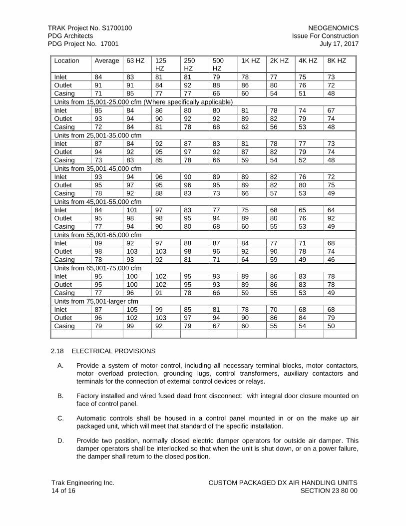
TRAK Project No. S1700100 NEOGENOMICS
PDG Architects Issue For Construction
PDG Project No. 17001 July 17, 2017
Trak Engineering Inc. CUSTOM PACKAGED DX AIR HANDLING UNITS
14 of 16 SECTION 23 80 00
Location Average 63 HZ 125
HZ
250
HZ
500
HZ
1K HZ 2K HZ 4K HZ 8K HZ
Inlet 84 83 81 81 79 78 77 75 73
Outlet 91 91 84 92 88 86 80 76 72
Casing 71 85 77 77 66 60 54 51 48
Units from 15,001-25,000 cfm (Where specifically applicable)
Inlet 85 84 86 80 80 81 78 74 67
Outlet 93 94 90 92 92 89 82 79 74
Casing 72 84 81 78 68 62 56 53 48
Units from 25,001-35,000 cfm
Inlet 87 84 92 87 83 81 78 77 73
Outlet 94 92 95 97 92 87 82 79 74
Casing 73 83 85 78 66 59 54 52 48
Units from 35,001-45,000 cfm
Inlet 93 94 96 90 89 89 82 76 72
Outlet 95 97 95 96 95 89 82 80 75
Casing 78 92 88 83 73 66 57 53 49
Units from 45,001-55,000 cfm
Inlet 84 101 97 83 77 75 68 65 64
Outlet 95 98 98 95 94 89 80 76 92
Casing 77 94 90 80 68 60 55 53 49
Units from 55,001-65,000 cfm
Inlet 89 92 97 88 87 84 77 71 68
Outlet 98 103 103 98 96 92 90 78 74
Casing 78 93 92 81 71 64 59 49 46
Units from 65,001-75,000 cfm
Inlet 95 100 102 95 93 89 86 83 78
Outlet 95 100 102 95 93 89 86 83 78
Casing 77 96 91 78 66 59 55 53 49
Units from 75,001-larger cfm
Inlet 87 105 99 85 81 78 70 68 68
Outlet 96 102 103 97 94 90 86 84 79
Casing 79 99 92 79 67 60 55 54 50
2.18 ELECTRICAL PROVISIONS
A. Provide a system of motor control, including all necessary terminal blocks, motor contactors,
motor overload protection, grounding lugs, control transformers, auxiliary contactors and
terminals for the connection of external control devices or relays.
B. Factory installed and wired fused dead front disconnect: with integral door closure mounted on
face of control panel.
C. Automatic controls shall be housed in a control panel mounted in or on the make up air
packaged unit, which will meet that standard of the specific installation.
D. Provide two position, normally closed electric damper operators for outside air damper. This
damper operators shall be interlocked so that when the unit is shut down, or on a power failure,
the damper shall return to the closed position.

TRAK Project No. S1700100 NEOGENOMICS
PDG Architects Issue For Construction
PDG Project No. 17001 July 17, 2017
Trak Engineering Inc. CUSTOM PACKAGED DX AIR HANDLING UNITS
15 of 16 SECTION 23 80 00
E. Provide a single point power connection with a factory mounted convenience circuit with two GFI
receptacles.
F. Provide all wiring in the air tunnel to be installed in conduit. Industrial color coded numbered
wiring and bus bar grounding.
G. Fan motors shall be factory mounted and wired to an external disconnect switch within sight of
the motor access door. Fan motors shall be interlocked with fan access door to shut down fan
when door is opened.
H. Disconnect switches and starters shall be mounted independent of the unit to allow for
maintenance access and access to AHU components. Locate disconnect switches within close
proximity and sight of the electrical component. Interlock fan motor starters with a position limit
switch located at the fan section access door. The limit switch shall de-energize the fan motor or
other electrical components when the access door is opened.
I. Provide vapor-proof, two-lamp linear fluorescent light fixtures with electronic ballasts, and water
proof GFI convenience outlets inside sections before and after coil; before filter, at fan and
before silencer compartments. Light fixtures in each air handling unit compartment shall be
independently switched. Wire lights and outlets to two external 120V, 20A power connections
(one for each service) for connection by Division 26. Fixtures and lamps shall comply with
Division 26 requirements.
J. All wiring shall be 600V rated type MTW/THWN #12 stranded copper in EMT or LiquidTite
conduit (maximum three feet). All junction boxes shall be UL approved and gasketed. All
conduits installed on the floor inside air handling units shall be rigid steel with steel fittings and
diecast boxes. All EMT conduit and fittings on unit walls and ceiling shall be steel, watertight
type.
K. Provide flexible connection to motor; 36-inch maximum length.
L. Conduit penetrations shall not represent through-metal contact. Penetrations shall be made and
sealed before unit factory testing.
M. The unit shall be designed for the electrical service designated on the Drawings.
N. Arrange electrical cabinet for connecting electrical service at one point only.
O. Power and control wiring of the unit shall be factory installed complete within the unit. Provide
correctly identified suitable lugs and terminal strips for field connection to electrical power and
external controls.
P. Factory equip unit with motor starters for each of the motor driven components.
PART 3 - EXECUTION
3.01 INSTALLATION
A. Installation shall meet or exceed all applicable federal, state and local requirements, referenced
standards and conform to codes and ordinances of authorities having jurisdiction.
B. All installation shall be in accordance with manufacturer’s published recommendations.
C.

TRAK Project No. S1700100 NEOGENOMICS
PDG Architects Issue For Construction
PDG Project No. 17001 July 17, 2017
Trak Engineering Inc. CUSTOM PACKAGED DX AIR HANDLING UNITS
16 of 16 SECTION 23 80 00
D. electric packaged air conditioning units shall be installed according to manufacturer's
recommendations to be completely weatherproof. Protect the roof from damage during
installation. Secure factory touch-up paint to repair scratches and minor damage to equipment
prior to Start-up.
E. Power wiring to the units, including externally mounted service disconnect switch, shall be
furnished and installed under Division 26. Installing Contractor shall be provided with the
manufacturer's Shop Drawings as required for power wiring installation.
F. Controls for conditioned spaces shall be as required under Division 25, Building Automation
System. Control wiring shall be under Division 23. Actual pulling of wires may be accomplished
by subcontract or Division 26 Contractor; however, Division 25 shall retain responsibility for
correctness of wiring, connections, and full operation of the control system.
3.02 TESTING
A. Equipment shall be cycled through all heating, cooling, and ventilation cycles to ensure proper
operation of all components and controls prior to test and balance.
B. At time of Start-up, manufacturer's representative shall visit the Project Site and verify that unit
installation and performance is satisfactory, and to make any adjustments or settings to unit
operating and safety controls that may be required.
C. Include Start-up checkout service of at least one working day for one service technician,
including a written report of operational check provided to the Owner. Owner’s Representative
may require that the Start-up service be performed with Owner’s attendance and on-site review.
D. Clean filters shall be placed within the unit at the time of Substantial Completion.
E. The installing contractor must be responsible for warranty service and maintenance after the
equipment is placed into operation.
END OF SECTION 23 62 13

TRAK Project No. S1700100 NEOGENOMICS
PDG Architects Issue For Construction
PDG Project No. 17001 July 17, 2017
Trak Engineering Inc. CUSTOM PACKAGED DX AIR HANDLING UNITS
1 of 16 SECTION 23 80 00
SECTION 23 62 13 – CUSTOM PACKAGED AIR COOLED DX AIR HANDLING UNITS
1.01 GENERAL
1.02 RELATED DOCUMENTS
A. Drawings and general provisions of the Contract, including General and Supplementary
Conditions and Division 01 Specification Sections, apply to this Section.
B. Specifications throughout all Divisions of the Project Manual are directly applicable to this Section,
and this Section is directly applicable to them.
1.03 SUMMARY
A. This specification pertains to MAU-1.
B. Perform all Work required to provide a fully packaged air-cooled, direct expansion (DX) air
conditioning (AC) unit. The packaged AC unit shall perform to manufacturer’s product data,
installation instructions, Start-up instructions and maintenance information indicated by all
Specification Sections, and Contract Documents with supplementary items necessary for proper
operation.
C. Air-cooled AC unit shall consist of hermetic screw compressor component utilizing R-134a or R-
410 refrigerant, evaporator coil, air-cooled condenser coil, condenser fans, supply fan, vibration
isolation assemblies, and microprocessor control center.
1.04 REFERENCE STANDARDS
A. The latest published edition of a reference shall be applicable to this Project unless identified by
a specific edition date.
B. All reference amendments adopted prior to the effective date of this Contract shall be applicable
to this Project.
C. All materials, installation and workmanship shall comply with the applicable requirements and
standards addressed within the following references:
1. ARI 340/360 - Commercial Unitary Air-Conditioning and Air-Source Heat Pump
Equipment.
2. ARI 410 - Standard for Forced-Circulation Air-Cooling and Air-Heating Coils.
3. ANSI/ASHRAE 15 - Safety Standard for Refrigeration Systems.
4. ASHRAE 90.1 - Energy Standard for Buildings Except Low High Rise Residential
Buildings.
5. ASHRAE 52.2 - Method of Testing General Ventilation Air-Cleaning Devices Used for
Removal Efficiency.
6. ANSI/AMCA Standard 210 - Laboratory Methods of Testing Fans for Aerodynamic
Performance Rating.
7. AMCA Publication 211 - Certified Ratings Program - Product Rating Manual for Fan Air
Performance.

TRAK Project No. S1700100 NEOGENOMICS
PDG Architects Issue For Construction
PDG Project No. 17001 July 17, 2017
Trak Engineering Inc. CUSTOM PACKAGED DX AIR HANDLING UNITS
2 of 16 SECTION 23 80 00
8. AMCA Standard 300 - Reverberant Room Method for Sound Testing of Fans.
9. AMCA Publication 311 - Certified Ratings Program.
10. AMBA Method of Evaluating Load Ratings of Bearings ANSI-11.
11. ANSI/AMCA Standard 204 - Balance Quality and Vibration Levels for Fans.
12. ASTM B-117 - Standard Practice for Operating Salt Spray (Fog) Apparatus.
13. ANSI Z21.47 - Gas-Fired Central Furnaces.
14. ANSI/ASHRAE Standard 135 BacNet - A Data Communication Protocol for Building
Automation and Control Network.
15. NFPA 90A - Standard for the Installation of Air-Conditioning and Ventilating Systems.
1.05 QUALITY ASSURANCE
A. The design of the unit shall be AGA and ARI certified as combination heating-cooling units for
rooftop installation.
B. Unit construction shall comply with ASHRAE 15 safety code, NEC, and
UL applicable codes.
C. Cooling capacity ratings shall be in accordance with ARI standard 210/240, most recent edition.
D. In no case shall the air cooled packaged DX air conditioning unit selected have an EER or
SEER (if cooling capacity is less than 65,000 Btu/hr) less than that specified in Table 6.8.1A of
AHSRAE 90.1.
E. Insulation and adhesive shall meet NFPA 90A requirements.
1.06 SUBMITTALS
A. Product Data:
1. Provide literature that indicates dimensions, weight, loading, clearances, capacities,
gauges, thickness, and finishes of materials, electrical characteristics and connections.
2. Rigging, installation, testing, Start-up and operating instructions, maintenance data
including type and quantity of oil and refrigerant change (pounds), parts lists, and
troubleshooting guide.
3. Data on energy input versus cooling load output from 100 percent to 20 percent of full load
with constant entering condenser air temperature.
4. Information about control and wiring diagrams.
5. Product test data on sound power levels for both fan inlet and outlet at the rated design
capacity.
6. Operating data such as fans speeds, compressor LRA and RA, sound levels
7. Product data on special condenser coating.
8. Product data on all condenser fan accessories such as controls.

TRAK Project No. S1700100 NEOGENOMICS
PDG Architects Issue For Construction
PDG Project No. 17001 July 17, 2017
Trak Engineering Inc. CUSTOM PACKAGED DX AIR HANDLING UNITS
3 of 16 SECTION 23 80 00
1.07 DELIVERY, STORAGE AND HANDLING
A. Deliver, store, protect and handle products to the Project Site under provisions of Division 01
and Division 20.
B. Accept products on Site in factory-fabricated protective containers or coverings, with factory-
installed shipping skids and lifting lugs. Inspect for damage.
C. Store in clean dry place and protect from weather and construction traffic. Handle carefully to
avoid damage to components, enclosures, and finish.
D. Check and maintain equipment on monthly basis to ensure equipment is being stored in
accordance with manufacturer’s recommended practices. Storage record shall be maintained
that indicates above requirements have been met.
1.08 EXTRA MATERIALS
A. Provide an additional replacement set of filters arranged for approximate filter face velocity of
300 feet per minute (fpm); maximum 350 fpm.
1.09 WARRANTY
A. Units shall be furnished with full coverage warranty against defects in materials. Warranty on
the complete unit shall be for one year from the Substantial Completion date. On the
compressors, warranty shall be for five (5) years from the Substantial Completion date.
B. Unit must be checked out, tested, and placed into operation under the supervision of an
authorized representative of the manufacturer. The manufacturer must warrant each product to
be free from defects in material and workmanship under normal and proper use for a period of
one (1) year from date of start up.
C. In addition, the manufacturer must warrant to the original purchaser-user the refrigerant
compressor to be free from defects in factory workmanship and material for a period of four (4)
years following the expiration of the standard one (1) year product warranty. This extended
warranty must cover the original motor compressor only and does not include any external parts,
electrical components, labor, refrigerant, freight charges or taxes. In the event a compressor is
replaced under this extended warranty, the replacement must carry the compressor
manufacturer’s replacement warranty for one (1) year from the date the replacement
compressor is purchased.
PART 2 - PRODUCTS
2.01 GENERAL
A. All materials shall meet or exceed all applicable referenced standards, federal, state and local
requirements, and conform to codes and ordinances of authorities having jurisdiction.
B. Factory assembled air-cooled packaged DX air conditioning unit using a refrigerant charge R-
134a or R-410 refrigerant with the following construction:
1. Double wall aluminum cabinet.
a. Factory control and electrical wiring and piping shall be contained within the unit
cabinet.
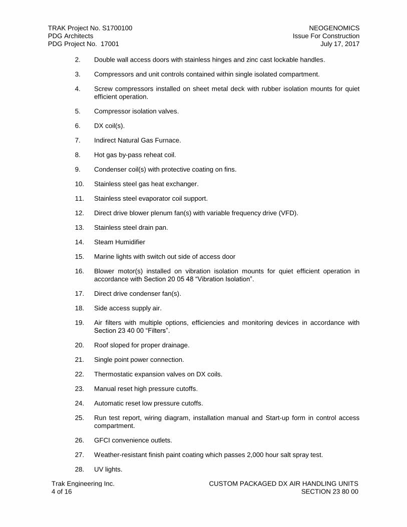
TRAK Project No. S1700100 NEOGENOMICS
PDG Architects Issue For Construction
PDG Project No. 17001 July 17, 2017
Trak Engineering Inc. CUSTOM PACKAGED DX AIR HANDLING UNITS
4 of 16 SECTION 23 80 00
2. Double wall access doors with stainless hinges and zinc cast lockable handles.
3. Compressors and unit controls contained within single isolated compartment.
4. Screw compressors installed on sheet metal deck with rubber isolation mounts for quiet
efficient operation.
5. Compressor isolation valves.
6. DX coil(s).
7. Indirect Natural Gas Furnace.
8. Hot gas by-pass reheat coil.
9. Condenser coil(s) with protective coating on fins.
10. Stainless steel gas heat exchanger.
11. Stainless steel evaporator coil support.
12. Direct drive blower plenum fan(s) with variable frequency drive (VFD).
13. Stainless steel drain pan.
14. Steam Humidifier
15. Marine lights with switch out side of access door
16. Blower motor(s) installed on vibration isolation mounts for quiet efficient operation in
accordance with Section 20 05 48 “Vibration Isolation”.
17. Direct drive condenser fan(s).
18. Side access supply air.
19. Air filters with multiple options, efficiencies and monitoring devices in accordance with
Section 23 40 00 “Filters”.
20. Roof sloped for proper drainage.
21. Single point power connection.
22. Thermostatic expansion valves on DX coils.
23. Manual reset high pressure cutoffs.
24. Automatic reset low pressure cutoffs.
25. Run test report, wiring diagram, installation manual and Start-up form in control access
compartment.
26. GFCI convenience outlets.
27. Weather-resistant finish paint coating which passes 2,000 hour salt spray test.
28. UV lights.

TRAK Project No. S1700100 NEOGENOMICS
PDG Architects Issue For Construction
PDG Project No. 17001 July 17, 2017
Trak Engineering Inc. CUSTOM PACKAGED DX AIR HANDLING UNITS
5 of 16 SECTION 23 80 00
C. Optional equipment:
1. Smoke detectors in supply air.
2. Phase and brown-out protection.
3. Disconnect switch.
4. Horizontal supply and return air curb.
5. Humidity control.
6. Variable Frequency drives in accordance with Section 23 05 13 “Variable Frequency
drive”.
D. Compressor shall have load capacity ratings per the requirements ARI 210/240.
E. Unit efficiency shall be in compliance with and the requirements of the International Energy
Conservation Code ASHRAE 90.1.
2.02 MANUFACTURERS
A. Carrier
B. Seasons-4, Inc.
C. AAON, Inc.
D. Engineered Air.
E. Innovent
2.03 CABINET FRAME AND INSULATION
A. The unit frame shall be constructed of heavy gauge galvanized steel with a formed galvanized
structural steel base. Lifting lugs shall be welded on the base frame for rigging the unit. All
exterior panels must be fabricated from Series 3105 aluminum alloy with an embossed textured
finish. Aluminum panels shall be minimum 0.063” aluminum inner and 0.080” aluminum outer
casing panels and shall be fastened to the frame with stainless steel bolts. Panels must be
isolated from the steel frame with dielectric gaskets to prevent galvanic corrosion. The roof of
the unit must be pitched to provide positive drainage. Top seams must be covered with cap
strips to prevent water leakage into the unit and the floor of each section shall have a galvanized
steel deck to isolate the entire unit from the building. All seams must be caulked with silicone
inside and out to prevent air and water leakage.
B. Access doors must be supported on full-length continuous aluminum hinges and shall have a
single handle with multiple latches to provide quick access. Doors must be provided for
entrance to all sections housing components requiring routine maintenance. Full height access
doors shall have stainless steel "hold back" latches to prevent door closure during the
performance of service procedures.
C. All walls, roof, and doors in the air-handling compartment shall be double wall construction
enclosing 2" thick fiberglass. Liners shall be galvanized steel sheet metal to protect the
insulation during routine service and maintenance operations. The floor of the air handling
sections must be insulated with 2" foil faced fiberglass. When the unit is mounted on an open
platform, the floor insulation must be protected from damage with a galvanized steel liner.

TRAK Project No. S1700100 NEOGENOMICS
PDG Architects Issue For Construction
PDG Project No. 17001 July 17, 2017
Trak Engineering Inc. CUSTOM PACKAGED DX AIR HANDLING UNITS
6 of 16 SECTION 23 80 00
D. Provide stainless steel lifting lugs to allow placement of the unit using a crane and sling.
E. The double wall weatherproof cabinet of the indoor air section shall be suitably insulated, and
have thermal breaks to prevent condensation on any cabinet surface exposed to outside
atmosphere conditions.
F. If the unit is not placed on a roof, make provisions to elevate and support the unit off the ground
or grade level to protect unit from standing in water.
2.04 COMPRESSORS/CONTROL VESTIBULE
A. Compressors and main control panel shall be mounted in a walk-in service vestibule having a
clear inside height of 78 inches as required by the National Electrical Code. Vestibule shall be
completely weatherproof with GFCI type convenience outlet and a marine type service light with
switch near the door, both wired to terminals for field connection to a 15 amp, 120 volt lighting
circuit. A thermostatically controlled ventilation fan shall be included in the vestibule. The floor of
the vestibule shall be insulated with 1", 3-lb. density foil faced insulation to minimize the
transmission of sound to the space below. The vestibule access door shall have a "padlock"
type latch and the floor must be aluminum diamond treadplate.
B. The multiple independent refrigerant circuits shall be completely piped, tested, dehydrated and
fully charged with oil and refrigerant R-134a. The refrigerant circuit components shall include
compressor, condenser with integral liquid sub cooling, liquid line service and charging valve,
filter drier in the liquid line, filter in the suction line, liquid line sight glass, and relief valve. Each
compressor shall have cylinder unloading reducing capacity to the minimum shown on the
schedule. The lead compressor on variable volume units shall have a hot gas bypass in
addition to cylinder unloading.
C. Vestibule shall be equipped with 5KW electric unit heater.
2.05 MECHANICAL COOLING
A. Compressors shall be type, 3600 RPM, set on resilient neoprene mounts and complete with live
voltage break internal overload protection and internal pressure relief valve. External crankcase
heaters locked out during compressor operation.
B. First stage of post cooling DX coil shall be digital scroll with infinite capacity modulation from
20% to 100% variable modulation. Set on resilient neoprene mounts and complete with live
voltage break internal overload protection. Internal pressure relief valve and external crankcase
heaters locked out during compressor operation.
C. Packaged Air Conditioning Units
1. Packaged units shall be CETL, ETLUS approved and operate down to 50°F(10°C) as
standard. Where applicable, multiple refrigeration circuits shall be separate from each
other. Refrigeration circuits shall be complete with liquid line filter-driers, and service ports
fitted with Schraeder fittings. Units with over 6 Ton hermetic compressors and all units
with semi-hermetic compressors shall also incorporate load compensated thermal
expansion valves with external equalizers and combination sight glass moisture indicators.
Semi-hermetic compressor units shall have condensers designed for 15°F (8°C) liquid
subcooling and be equipped with suction line filters and liquid line manual shutoff valves.
The complete piping system shall be purged and pressure tested with dry nitrogen, then
tested again under vacuum. Each system shall be factory run and adjusted prior to
shipment.

TRAK Project No. S1700100 NEOGENOMICS
PDG Architects Issue For Construction
PDG Project No. 17001 July 17, 2017
Trak Engineering Inc. CUSTOM PACKAGED DX AIR HANDLING UNITS
7 of 16 SECTION 23 80 00
2. Packaged units shall be supplied with R-410refrigerant.
3. Controls for hermetic compressor units shall include compressor and condenser fan motor
contactors, supply fan contactors and overload protection, control circuit transformer,
cooling relays, ambient compressor lockout, automatic reset low pressure controls, and
manual reset high pressure controls on compressors over 6 tons. Head pressure
actuated fan cycling control provided on all multiple condenser fan units.
4. Modulating condenser reheat coil with stepper valve infinite modulating control to either
independent condenser reheat coil or remote condenser. System must include receiver(s),
subcooling condenser circuit(s) and check valves.
5. Provide five minute anti-cycle timers and interstage time delay timers.
6. Provide hot gas bypass on the lead compressor to maintain adequate suction pressure in
the event of low loads. This feature shall be provided on all VAV and Make Up Air
applications with less than four stages of cooling control.
7. Compressors shall be located in a service enclosure under condenser section complete
with deluxe hinged access doors leverlok handles for ease of service. Provide Rotolock
valves for easy removal of compressor during service.
8. Provide premium efficiency Ziehl Abbeg condenser fans – direct drive propeller type
9. Provide condenser coil hail guards.
2.06 COMPRESSORS-SCREW (ALTERNATE)
A. Compressors shall be heavy duty suction cooled nominal 3,600 RPM rotary screw type complete
with an internal oil separation system, oil sump and oil filter. Each compressor shall be a single
stage, semi-hermetic type and have positive displacement, eliminating re-expansion of
compressed refrigerant gas. Compressors are equipped with an integral solid state 3-phase
monitor to prevent backward rotation of the screws. Capacity control is achieved through a slide
valve which is infinitely variable between 100% load and 25-35% load, depending on
compressor model. Compressor is equipped with suction and discharge service valves,
discharge check valve, suction strainer, oil level sight glass, crankcase heater, internal 3-phase
thermal motor protection. All compressor safety shutdown devices shall be factory installed. The
compressors are mounted on rubber-in-shear vibration isolators which in turn are mounted on a
specially designed mounting frame to prevent transmission of any remaining vibration energy to
the space below.
B. The multiple independent refrigerant circuits are completely piped, tested, dehydrated and fully
charged with oil and refrigerant. The refrigerant circuit components include compressor,
condenser with integral liquid sub-cooling, liquid line service and charging valve, replaceable
core filter drier in the liquid line, and a replaceable core filter in the suction line, liquid line sight
glass, and relief valve.
2.07 FANS, MOTORS, AND DRIVES
A. Fans shall be in accordance with Section 23 34 16 “Centrifugal Fans” The supply of air blower
wheels shall be a single width/single inlet airfoil plenum type, secured to a machined, ground
and polished solid steel shaft. The shaft shall be coated with a rust inhibitor and supported by
two outboard bearings. The complete blower assembly must be dynamically balanced.
Bearings shall be self-aligning ball bearing pillow block type and be designed for an L-10 life of
200,000 hours.

TRAK Project No. S1700100 NEOGENOMICS
PDG Architects Issue For Construction
PDG Project No. 17001 July 17, 2017
Trak Engineering Inc. CUSTOM PACKAGED DX AIR HANDLING UNITS
8 of 16 SECTION 23 80 00
B. Blower drive shall include fixed pitch sheaves with multiple V-belts having a minimum service
factor of 150%. On constant air volume units, manufacturer shall provide one extra set of
sheaves to be installed by the installing contractor after initial air balance is completed. Motors
shall be premium efficiency heavy-duty TEFC 3-phase, 1800 rpm, mounted on a heavy-duty
sliding base. Motor and blower assembly shall be supported by springs with a minimum
deflection of 2 inches. In addition to the spring isolators, the blower assembly must have seismic
restraints.
C. Each blower’s speed shall be controlled by its own Variable Frequency Drive (VFD) housed in a
UL listed NEMA 4 enclosure, factory mounted and wired in the ventilated control vestibule. The
drive shall be an advanced microprocessor type utilizing a PWM/Voltage Vector design
technique. Refer to specification section 23 05 13 “Variable Frequency Drives”. Six-step and
current source drives are not acceptable. Drive shall include line side reactors. Unit shall
include controls to provide variable air volume and maintain constant static pressure at the field
mounted pressure sensor in the supply duct. Provide a manually reset adjustable range high-
pressure safety switch to prevent excessive pressure in the supply duct.
D. Blower section has two blower fans for redundancy purposes. Each blower has it own gravity
type isolation damper. The blowers are to be switched manually as needed.
E. Indoor airflow and external static pressure capabilities shall be no less than the values indicated
on the Drawings. Internal static pressure shall include a minimum allowance for 2-inch pleated
type filters.
F. All fan(s) and motor(s) shall be in compliance with the fan power limitation in Table 6.5.3.1 of
ASHRAE 90.1 and shall be in accordance with Section 20 05 13 “Motors”.
G. Outdoor fans shall be direct drive, shaft mounted propeller type, statically and dynamically
balanced. Outdoor fan motor(s) shall be TEFC weather resistant with permanently lubricated
bearings.
2.08 AIR COOLED CONDENSING SECTION
A. The air-cooled condensing section must be designed and manufactured by the unit
manufacturer. Units incorporating condensing sections manufactured by a third party and bolted
to the unit frame or field piped are not acceptable. The floor of the air-cooled condensing
section shall be crowned for water drainage and constructed of aluminum to resist the corrosive
effects of the weather. All refrigerant piping shall be installed and tested in the factory prior to
shipment of the complete unit.
B. The air-cooled condenser coils must be a minimum of four rows deep and have copper tubes
expanded into a maximum of ten aluminum fins per inch and designed for 105 degree F.
ambient conditions. The entire coil shall be Electro-fin coated for corrosion protection. Coils shall
be tested at 425 PSIG and mounted vertically for complete surface utilization. Coils shall be
counter flow with a minimum of 10 degrees of liquid sub-cooling and have adequate capacity to
dissipate the total heat rejection of the system at design conditions. Condensers shall have
guards to protect the coils from vandalism and weather related damage including hail.
C. CONDENSER COIL: The condenser coil shall be constructed of 3/8” minimum OD seamless
copper tubes with .0055” thick formed aluminum fins. Headers shall be seamless copper with
non-ferrous connections. Coil casings shall be minimum 18-gauge die-formed galvanized steel
flange. Each refrigeration circuit shall be provided with a condenser coil. Water cooled units
shall be provided with coaxial tube-in-tube condensers. The heat exchangers shall be provided
with cupro-nickel tubes and carbon steel shell.

TRAK Project No. S1700100 NEOGENOMICS
PDG Architects Issue For Construction
PDG Project No. 17001 July 17, 2017
Trak Engineering Inc. CUSTOM PACKAGED DX AIR HANDLING UNITS
9 of 16 SECTION 23 80 00
D. Condenser fans shall be coated steel and have a steel hub locked on a stainless steel motor
shaft with a keyway and square head set screws. Provide radius spun type venturi for efficient
performance. Fans shall have vinyl coated external guards capable of being removed for
service without removing the fan motor. Fans shall be direct driven by NEMA constructed, three
phase motors operating at 1140 or 1750 RPM. Motors must have stainless steel shafts to
prevent "rust welding" of the fan hubs to the shaft. Each motor shall have a shaft slinger to
prevent water seepage into the motor.
E. Condenser head pressure shall be controlled and maintained down to an ambient of 38 Deg F.
2.09 AIR FILTERS
A. Front frame loaded filters shall be easily accessible for removal through access panels or doors.
B. Filters shall in accordance with Section 23 40 00 “Filters” and with ASHRAE Standard 52.2.
Furnish additional filter casings and filters per the Drawings. Provide MERV efficiency indicated
below:
1. Pre-filter – MERV 7
2. Final Filter – MERV 14
2.10 COILS AND CAPACITY CONTROL
A. Coils shall be constructed with copper tubes with aluminum fins. All copper work shall be
brazed. Coils shall be factory pressure tested.
B. Indoor coils shall be capable of the performance indicated on the Drawings with no “blow-off” of
condensate.
C. Indoor coils shall be equipped with a sloped, 316 stainless steel condensate pan terminating at a
condensate drain located outside the unit cabinet.
D. The refrigeration system shall be equipped with filter dryers on the liquid lines and service valves
with gauge port connections on the discharge and suction lines.
E. Unit shall be provided with an Evaporative Refrigeration Coils that shall provide a continuous
amount of cooling that will not cause varying discharge air temperatures from the unit under
varying load conditions. Heat exchanger coils shall be constructed of 3/8” minimum OD
seamless copper tubes with .0055” thick formed aluminum fins. Headers shall be seamless
copper with non-ferrous connections. Coil casings shall be minimum 18-gauge die-formed
galvanized steel flanges and shall be provided with a removable casing panel for access to the
fins for cleaning.
F. Coils shall be leak tested at 425 PSIG pressure under water, suitable for 200-PSI working
pressure and be manufacturer certified as complying with ARI STD 410. Distributors shall be
venturi type. Unit shall be provided with multiple independent refrigeration circuits to assure
design dew point is achieved on the process air stream under full and part load conditions. The
minimum allowable fin spacing is 10 fins per inch and the maximum allowable fin spacing is 12
fins per inch.
G. UV lighting shall be located on the downstream airside of the cooling coil. UV light density shall
have the intensity to preclude algae growth in the drip pan and dirt build-up on coil tubes and
fins.

TRAK Project No. S1700100 NEOGENOMICS
PDG Architects Issue For Construction
PDG Project No. 17001 July 17, 2017
Trak Engineering Inc. CUSTOM PACKAGED DX AIR HANDLING UNITS
10 of 16 SECTION 23 80 00
2.11 CORROSION PROTECTIVE COATINGS
A. Unit shall be provided with Corrosion Protective Coating Packages. Coil Package shall have
baked on Electro-Fin polymeric coating applied in a submersion / dip process on all copper tube
/ aluminum fin coils.
2.12 INDIRECT GAS FURNANCE:
A. Shall be ETL Certified as a component of the unit.
B. Shall have an integral combustion gas blower.
C. Shall be ETL Certified for installation downstream of a cooling coil.
D. Shall have fault sensors to provide fault conditions to optional digital controller or building
controls.
E. Shall have 4-pass tubular heat exchangers, constructed of type 409 stainless steel. Heat
exchanger tubes shall be installed on the vest plate by means of swaged assembly, welded
connections are not acceptable. Heat exchanger tubes shall be supported by a minimum of two
fabricated assemblies that support the tubes and also permit expansion and contraction of the
tubes. Welded connections between heat exchanger tubes and the vest plate are known to be a
source of failure due to expansion and contraction. 409 stainless steel is considered the most
suitable material for high temperature gases, such as automotive exhausts. Manufacturer
recommends the use of stainless steel heat exchangers for applications with a temperature rise
of 60° F or more. Tubular heat exchangers are considered the industry standard, but some
manufacturers are known to construct “clamshell” or other type exchangers. The same
requirements for material types and assembly methods and supports should apply to all.
F. Heat exchanger shall have a 5 year extended warranty. 5 year and ten year extended warranties
are only for stainless steel heat exchangers
G. Furnace control shall be modulating High Turndown with minimum 16:1 turndown.
H. Shall be encased in a weather-tight metal housing with intake air vents. Large, metal lift-off door
shall provide easy access to the enclosed vest plate, control circuitry, gas train, burner
assembly, and exhaust blower. Indicate any other requirements such as furnace output,
controls, etc.
I. Shall have solid state controls permitting stand-alone operation or control by building controllers.
2.13 HOT GAS REHEAT COIL
A. The unit shall be provided with a hot gas reheat coil positioned downstream of the evaporator
coils to reheat the discharge air to a controllable temperature.
B. The hot gas reheat coil shall be constructed of 3/8” minimum OD seamless copper tubes with
.0055” thick formed aluminum fins. Headers shall be seamless copper with non-ferrous
connections.
C. Coil casings shall be minimum 18-gauge die-formed galvanized steel flange.
D. The unit shall use analog controlled modulating refrigerant flow controls to provide the amount of
reheat provided. The electronic flow controls shall be modulated by the unit’s internal controller
to maintain a constant discharge air temperature +/- 0.5° F under any conditions.

TRAK Project No. S1700100 NEOGENOMICS
PDG Architects Issue For Construction
PDG Project No. 17001 July 17, 2017
Trak Engineering Inc. CUSTOM PACKAGED DX AIR HANDLING UNITS
11 of 16 SECTION 23 80 00
E. Coils shall be leak tested at 425 PSIG pressure under water, suitable for 200-PSI working
pressure and be manufacturer certified as complying with ARI STD 410.
2.14 DRAIN PAN
A. The primary drain pan shall be 3” deep fabricated of 18 gauge welded 304L stainless steel with
MPT stainless pipe drain connections, and shall be pitched to provide full drainage of pan
through side connection. Pans shall be configured to allow washing of entire pan area while
preventing accumulation of debris at bottom of pan.
2.15 ULTRA VIOLET GERMICIDAL IRRADIATION SYSTEMS:
A. Ultraviolet lighting system shall be an integral part of the Air Handling Unit and wired at the
factory. All UV lamps shall be sleeved to protect against moisture and physical damage. UV
lamps shall be assembled on a stainless steel rack and placed in an arrangement between 6 to
12 inches from the surface for maximum biological kill.
B. Drain pan(s) shall be irradiated by a single row of horizontal lamp(s). When intermediate drain
pans are provided, each intermediate drain pan shall be irradiated by a single row of horizontal
lamp(s). The lamps shall be mounted directly above the drainage surface. The minimum UVC
intensity delivered anywhere in the fast pan shall be 212 µW/cm2.
C. The downstream face of the cooling coil is to be irradiated by row(s) of horizontal UVC lamps.
The maximum height, of a cooling coil face, that a single row of lamps can irradiate is 18 inches.
Maximum distance, between rows of lamps, shall be 50 inches. Maximum gap, measured
horizontally from the end of any lamp to the ends of the cooling coil, shall be 6 inches. Minimum
intensity, delivered anywhere on the cooling coil face, shall be 147 µW/cm2. Minimum intensity,
delivered at the center of the lamp, perpendicular to cooling coil face shall be 514 µW/cm2.
D. UV lamps shall be located:
a. Downstream of cooling coils.
b. Above condensate drain pans.
c. Up-stream of final filtration sections.
2. Lamps shall be UL listed for application in air handling systems.
3. Lighting systems shall be vapor proof with electronic ballasts and shall be wired.
4. UV Light fixtures shall be capable of being switched on and off at the respective AHU
section access door.
5. Lamps shall be interlocked with access door position limit switches such that they are de-
energize when the doors open.
6. Lamps shall be installed on a stainless steel grid in accordance with the manufacturer’s
installation instructions.
7. Units with view ports from which the lamps can be seen shall be labeled to warn of
possible eye damage.
8. Replacement lamps for UV systems shall be standard types which are not proprietary and
are available from multiple sources.

TRAK Project No. S1700100 NEOGENOMICS
PDG Architects Issue For Construction
PDG Project No. 17001 July 17, 2017
Trak Engineering Inc. CUSTOM PACKAGED DX AIR HANDLING UNITS
12 of 16 SECTION 23 80 00
E. BALLAST & LAMP MODULES
1. Ballasts shall be instant start type. Supply voltage shall be 120 VAC, 60 Hz, 1 Ph.
2. Sleeved lamp modules shall be low-pressure mercury vapor lamps. The lamp glass and
sleeve glass shall be hard quartz glass. The sleeve shall be an integral part of the lamp.
Lamp base shall be made from ozone and UV resistant ceramic material. Supply power to
the lamp module shall be connected at one end of the module through a plenum rated
cord. Lamp connector shall mate with ballast connector. The lamp portion of the UVC
only lamp modules shall be 22, 34 and 46 inches long. The lamp portion of the dual
frequency lamp modules shall be 12 and 24 inches long. Lamps shall be internally coated
to extend life. Lamp life shall be rated for 9000 hours of continuous operation. The lamps
shall be rated for a minimum of 1500 starting cycles. Maximum diameter of sleeved lamp
modules shall be 1.00 inches.
2.16 CONTROLS
A. Integral Unit Controls: As a minimum, the packaged AC unit’s components shall be protected
with high pressure-stat, loss-of-charge protection, current and temperature sensitive overload
devices, and anti-short cycle timer control circuit to prevent the compressor from restarting for
five (5) minutes after stopping.
B. The microprocessor controller provided by the equipment manufacturer shall be shall be in
accordance with Division 25 Specifications.
C. The main control panel and disconnect switch shall be mounted in the weatherproof service
vestibule. Unit shall be complete with all safety and operating controls factory installed and
wired except for remote mounted components, which shall be field installed by the contractor.
The main control panel shall include the following:
1. A power terminal block for single point power supply with factory mounted branch circuit
fuses for all circuits.
2. A 24-volt control transformer and 24-volt field wiring control terminal strip. Terminals shall
be numbered for field connection of all controls in accordance with the wiring diagram. All
wiring shall be numbered and/or color-coded.
3. A phase failure monitor and low voltage protection relay.
4. All refrigeration safety and operating controls.
5. Unit power and control wiring diagrams laminated to the door of the control panel.
6. 15-amp GFCI type convenience outlet factory mounted and wired to terminals for field
connection to a 120-volt building lighting circuit. Additional lights and outlets shall be
included where indicated on the plans.
7. Blower motor starters with three-phase overloads factory mounted and wired. (Not
required when VFD's are used.)
8. Compressor and condenser fan motor starters and refrigeration operating and safety
controls.
9. Condensing unit low ambient lockout set at 38°F.
10. Temperature controls as required to accomplish the sequence of control specified below.

TRAK Project No. S1700100 NEOGENOMICS
PDG Architects Issue For Construction
PDG Project No. 17001 July 17, 2017
Trak Engineering Inc. CUSTOM PACKAGED DX AIR HANDLING UNITS
13 of 16 SECTION 23 80 00
D. The above components are in addition to electrical components associated with other sections,
which must be incorporated in the main control panel to facilitate maintenance and
troubleshooting. All components shall be identified with nametags and wired in accordance with
the National Electrical Code.
E. Equipment manufacturer shall include on-site programming assistance to both the Owner and
BAS Provider to:
1. Assure that data from their respective interface is available.
2. Assist the BAS Provider to establish proper communication.
3. Confirm that the interface and controller are operating in accordance with sequence of
operation.
4. Provide software or hardware tools as required to operate and checkout the controller
interface.
F. Insulate all surfaces expected to be at or below a dew point temperature of 87 degrees F to
prevent condensation.
G. DDC TEMPERATURE CONTROLS
1. Operation of the cooling and heating sections of the unit shall be controlled by a
microprocessor-based controller fully capable of stand-alone direct digital operation
utilizing its own processor, non-volatile memory, input/output, A to D conversion,
clock/calendar and voltage transient and lightning protection devices. All non-volatile
memory shall have a battery backup of at least five years.
H. OTHER CONTROLS
1. Unit shall have manual reset firestats factory mounted and wired in the supply and return
openings to the unit. Upon detection of excess heat, fans must stop and a signal shall be
sent to the building fire alarm system. Installing contractor shall coordinate this interlock
with the building systems.
2. Unit shall have manual reset photo electronic type smoke detectors factory mounted and
wired in the supply openings to the unit. Upon detection of smoke, fans must stop and a
signal shall be sent to the building fire alarm system. Installing contractor shall coordinate
this interlock with the building systems.
3. Unit shall have terminal strips and interlocking relays factory mounted and wired to
interlock with other components of the building. It is the responsibility of the installing
contractor to advise the manufacturer of requirements for additional interlocks not covered
in this specification.
2.17 SOUND CHARACTERISTICS
A. The air handling unit sound power levels must not exceed the following criteria. Sound power
levels scheduled on Drawings shall supercede the values below:
Location Average 63 HZ 125
HZ
250
HZ
500
HZ
1K HZ 2K HZ 4K HZ 8K HZ
Units from 10,000-15,000 cfm (Where specifically applicable)

TRAK Project No. S1700100 NEOGENOMICS
PDG Architects Issue For Construction
PDG Project No. 17001 July 17, 2017
Trak Engineering Inc. CUSTOM PACKAGED DX AIR HANDLING UNITS
14 of 16 SECTION 23 80 00
Location Average 63 HZ 125
HZ
250
HZ
500
HZ
1K HZ 2K HZ 4K HZ 8K HZ
Inlet 84 83 81 81 79 78 77 75 73
Outlet 91 91 84 92 88 86 80 76 72
Casing 71 85 77 77 66 60 54 51 48
Units from 15,001-25,000 cfm (Where specifically applicable)
Inlet 85 84 86 80 80 81 78 74 67
Outlet 93 94 90 92 92 89 82 79 74
Casing 72 84 81 78 68 62 56 53 48
Units from 25,001-35,000 cfm
Inlet 87 84 92 87 83 81 78 77 73
Outlet 94 92 95 97 92 87 82 79 74
Casing 73 83 85 78 66 59 54 52 48
Units from 35,001-45,000 cfm
Inlet 93 94 96 90 89 89 82 76 72
Outlet 95 97 95 96 95 89 82 80 75
Casing 78 92 88 83 73 66 57 53 49
Units from 45,001-55,000 cfm
Inlet 84 101 97 83 77 75 68 65 64
Outlet 95 98 98 95 94 89 80 76 92
Casing 77 94 90 80 68 60 55 53 49
Units from 55,001-65,000 cfm
Inlet 89 92 97 88 87 84 77 71 68
Outlet 98 103 103 98 96 92 90 78 74
Casing 78 93 92 81 71 64 59 49 46
Units from 65,001-75,000 cfm
Inlet 95 100 102 95 93 89 86 83 78
Outlet 95 100 102 95 93 89 86 83 78
Casing 77 96 91 78 66 59 55 53 49
Units from 75,001-larger cfm
Inlet 87 105 99 85 81 78 70 68 68
Outlet 96 102 103 97 94 90 86 84 79
Casing 79 99 92 79 67 60 55 54 50
2.18 ELECTRICAL PROVISIONS
A. Provide a system of motor control, including all necessary terminal blocks, motor contactors,
motor overload protection, grounding lugs, control transformers, auxiliary contactors and
terminals for the connection of external control devices or relays.
B. Factory installed and wired fused dead front disconnect: with integral door closure mounted on
face of control panel.
C. Automatic controls shall be housed in a control panel mounted in or on the make up air
packaged unit, which will meet that standard of the specific installation.
D. Provide two position, normally closed electric damper operators for outside air damper. This
damper operators shall be interlocked so that when the unit is shut down, or on a power failure,
the damper shall return to the closed position.

TRAK Project No. S1700100 NEOGENOMICS
PDG Architects Issue For Construction
PDG Project No. 17001 July 17, 2017
Trak Engineering Inc. CUSTOM PACKAGED DX AIR HANDLING UNITS
15 of 16 SECTION 23 80 00
E. Provide a single point power connection with a factory mounted convenience circuit with two GFI
receptacles.
F. Provide all wiring in the air tunnel to be installed in conduit. Industrial color coded numbered
wiring and bus bar grounding.
G. Fan motors shall be factory mounted and wired to an external disconnect switch within sight of
the motor access door. Fan motors shall be interlocked with fan access door to shut down fan
when door is opened.
H. Disconnect switches and starters shall be mounted independent of the unit to allow for
maintenance access and access to AHU components. Locate disconnect switches within close
proximity and sight of the electrical component. Interlock fan motor starters with a position limit
switch located at the fan section access door. The limit switch shall de-energize the fan motor or
other electrical components when the access door is opened.
I. Provide vapor-proof, two-lamp linear fluorescent light fixtures with electronic ballasts, and water
proof GFI convenience outlets inside sections before and after coil; before filter, at fan and
before silencer compartments. Light fixtures in each air handling unit compartment shall be
independently switched. Wire lights and outlets to two external 120V, 20A power connections
(one for each service) for connection by Division 26. Fixtures and lamps shall comply with
Division 26 requirements.
J. All wiring shall be 600V rated type MTW/THWN #12 stranded copper in EMT or LiquidTite
conduit (maximum three feet). All junction boxes shall be UL approved and gasketed. All
conduits installed on the floor inside air handling units shall be rigid steel with steel fittings and
diecast boxes. All EMT conduit and fittings on unit walls and ceiling shall be steel, watertight
type.
K. Provide flexible connection to motor; 36-inch maximum length.
L. Conduit penetrations shall not represent through-metal contact. Penetrations shall be made and
sealed before unit factory testing.
M. The unit shall be designed for the electrical service designated on the Drawings.
N. Arrange electrical cabinet for connecting electrical service at one point only.
O. Power and control wiring of the unit shall be factory installed complete within the unit. Provide
correctly identified suitable lugs and terminal strips for field connection to electrical power and
external controls.
P. Factory equip unit with motor starters for each of the motor driven components.
PART 3 - EXECUTION
3.01 INSTALLATION
A. Installation shall meet or exceed all applicable federal, state and local requirements, referenced
standards and conform to codes and ordinances of authorities having jurisdiction.
B. All installation shall be in accordance with manufacturer’s published recommendations.
C.

TRAK Project No. S1700100 NEOGENOMICS
PDG Architects Issue For Construction
PDG Project No. 17001 July 17, 2017
Trak Engineering Inc. CUSTOM PACKAGED DX AIR HANDLING UNITS
16 of 16 SECTION 23 80 00
D. electric packaged air conditioning units shall be installed according to manufacturer's
recommendations to be completely weatherproof. Protect the roof from damage during
installation. Secure factory touch-up paint to repair scratches and minor damage to equipment
prior to Start-up.
E. Power wiring to the units, including externally mounted service disconnect switch, shall be
furnished and installed under Division 26. Installing Contractor shall be provided with the
manufacturer's Shop Drawings as required for power wiring installation.
F. Controls for conditioned spaces shall be as required under Division 25, Building Automation
System. Control wiring shall be under Division 23. Actual pulling of wires may be accomplished
by subcontract or Division 26 Contractor; however, Division 25 shall retain responsibility for
correctness of wiring, connections, and full operation of the control system.
3.02 TESTING
A. Equipment shall be cycled through all heating, cooling, and ventilation cycles to ensure proper
operation of all components and controls prior to test and balance.
B. At time of Start-up, manufacturer's representative shall visit the Project Site and verify that unit
installation and performance is satisfactory, and to make any adjustments or settings to unit
operating and safety controls that may be required.
C. Include Start-up checkout service of at least one working day for one service technician,
including a written report of operational check provided to the Owner. Owner’s Representative
may require that the Start-up service be performed with Owner’s attendance and on-site review.
D. Clean filters shall be placed within the unit at the time of Substantial Completion.
E. The installing contractor must be responsible for warranty service and maintenance after the
equipment is placed into operation.
END OF SECTION 23 62 13

TRAK Project No. S1700100 NEOGENOMICS
PDG Architects Issue For Construction
PDG Project No. 17001 July 17, 2017
Trak Engineering Inc. ELECTRIC DUCT HEATERS
1 of 4 SECTION 23 82 33
SECTION 23 82 33 – ELECTRIC DUCT HEATERS
PART 1 - GENERAL
1.01 RELATED DOCUMENTS
A. Drawings and general provisions of the Contract, including General and Supplementary
Conditions and Division 01 Specification Sections, apply to this Section.
B. Specifications throughout all Divisions of the Project Manual are directly applicable to this
Section, and this Section is directly applicable to them.
1.02 SUMMARY
A. Perform all Work required to provide and install the following electric duct heaters indicated by
the Contract Documents with supplementary items necessary for proper installation.
B. Refer to Division 26 sections for the following Work:
1. Power supply wiring from power source to power connection on terminal unit. Include
starters, disconnects, and required electrical devices, except where specified as
furnished, or factory-installed, by manufacturer.
2. Interlock wiring between electrically-operated terminal units and between terminal units
and field-installed control devices.
3. Interlock wiring specified as factory-installed is Work of this Section.
C. Provide the following as Work of this Section, complying with requirements of Division 26
Sections:
1. Control wiring between field-installed controls, indicating devices, and terminal unit control
panels.
1.03 REFERENCE STANDARDS
A. The latest published edition of a reference shall be applicable to this Project unless identified
by a specific edition date.
B. All reference amendments adopted prior to the effective date of this Contract shall be
applicable to this Project.
C. All materials, installation and workmanship shall comply with the applicable requirements and
standards addressed within the following references:
1. ARI Standard 410 - Forced-Circulation Air-Cooling and Air-Heating Coils.
2. ASHRAE Standard 33 - Methods of Testing Forced Circulation Air Cooling and Heating
Coils.
3. National Fire Protection Association (NFPA) 70, National Electrical Code.
4. ANSI/UL 883 - Safety Standards for Fan Coil Units and Room Fan Heater Units.
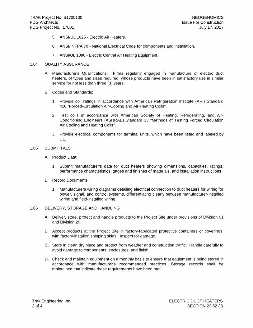
TRAK Project No. S1700100 NEOGENOMICS
PDG Architects Issue For Construction
PDG Project No. 17001 July 17, 2017
Trak Engineering Inc. ELECTRIC DUCT HEATERS
2 of 4 SECTION 23 82 33
5. ANSI/UL 1025 - Electric Air Heaters.
6. ANSI/ NFPA 70 - National Electrical Code for components and installation.
7. ANSI/UL 1096 - Electric Central Air Heating Equipment.
1.04 QUALITY ASSURANCE
A. Manufacturer's Qualifications: Firms regularly engaged in manufacture of electric duct
heaters, of types and sizes required, whose products have been in satisfactory use in similar
service for not less than three (3) years.
B. Codes and Standards:
1. Provide coil ratings in accordance with American Refrigeration Institute (ARI) Standard
410 "Forced-Circulation Air-Cooling and Air-Heating Coils".
2. Test coils in accordance with American Society of Heating, Refrigerating, and Air-
Conditioning Engineers (ASHRAE) Standard 33 "Methods of Testing Forced Circulation
Air Cooling and Heating Coils".
3. Provide electrical components for terminal units, which have been listed and labeled by
UL.
1.05 SUBMITTALS
A. Product Data:
1. Submit manufacturer's data for duct heaters showing dimensions, capacities, ratings,
performance characteristics, gages and finishes of materials, and installation instructions.
B. Record Documents:
1. Manufacturers wiring diagrams detailing electrical connection to duct heaters for wiring for
power, signal, and control systems, differentiating clearly between manufacturer-installed
wiring and field-installed wiring.
1.06 DELIVERY, STORAGE AND HANDLING
A. Deliver, store, protect and handle products to the Project Site under provisions of Division 01
and Division 20.
B. Accept products at the Project Site in factory-fabricated protective containers or coverings,
with factory-installed shipping skids. Inspect for damage.
C. Store in clean dry place and protect from weather and construction traffic. Handle carefully to
avoid damage to components, enclosures, and finish.
D. Check and maintain equipment on a monthly basis to ensure that equipment is being stored in
accordance with manufacturer’s recommended practices. Storage records shall be
maintained that indicate these requirements have been met.

TRAK Project No. S1700100 NEOGENOMICS
PDG Architects Issue For Construction
PDG Project No. 17001 July 17, 2017
Trak Engineering Inc. ELECTRIC DUCT HEATERS
3 of 4 SECTION 23 82 33
PART 2 - PRODUCTS
2.01 GENERAL
A. All materials shall meet or exceed all applicable referenced standards, federal, state and local
requirements, and conform to codes and ordinances of authorities having jurisdiction.
B. Electric duct heaters of types, sizes, ratings, and characteristics indicated.
C. Heating Elements: Open coil of resistance wire, 80 percent nickel and 20 percent chromium,
supported and insulted by floating ceramic bushings. Recess bushings into casing opening
and fasten to supporting brackets. Mounted in galvanized-steel frame.
D. Coil Layout: Horizontal (air flow vertical) or Vertical (air flow horizontal).
E. Casing Assembly: Slip-in type, galvanized-steel frame.
F. Over-Temperature Protection:
1. Serviceable through terminal unit without removing heater from duct or unit.
2. Disk-type, automatic reset, thermal-cutout safety devices for primary over-temperature
protection.
3. Load carrying, manual reset or manually replaceable thermal cutouts, factory wired in
series with each heater stage for secondary protection.
4. Airflow switch, diaphragm operated differential pressure switch to prevent duct heater
from operating when there is no air flow.
G. Control Panel: Mounted on unit, with means of a safety disconnect and overcurrent
protection. Include the following controls:
1. silicon-controlled rectifier (SCR)
2. 4 to 20 ma or 1 to 10 Volt input signal for SCR.
3. Time-delay relay.
4. Pilot lights; one per step, “power on”, and “low air flow”.
5. Provide common ohmic voltage and milli-amp alarm signals to the building automation
system (BAS).
6. Provide single point power connection.
H. Permanently attach a separate, complete, and specific wiring diagram to each heater. Typical
wiring diagrams are not acceptable. Clearly mark power and control terminals in terminal unit
identical to the wiring diagram.
2.02 MANUFACTURERS
A. Chromalox.
B. Indeeco.

TRAK Project No. S1700100 NEOGENOMICS
PDG Architects Issue For Construction
PDG Project No. 17001 July 17, 2017
Trak Engineering Inc. ELECTRIC DUCT HEATERS
4 of 4 SECTION 23 82 33
C. Markel Products Co.
D. Nailor Industries, Inc.
E. Trane Inc.
PART 3 - EXECUTION
3.01 INSTALLATION
A. Installation shall meet or exceed all applicable federal, state and local requirements,
referenced standards and conform to codes and ordinances of authorities having jurisdiction.
B. All installation shall be in accordance with manufacturer’s published recommendations.
C. Inspect areas and conditions under which terminal units are to be installed. Do not proceed
with Work until unsatisfactory conditions have been corrected in manner acceptable to
installer.
D. Do not operate electric heaters for any purpose until ductwork is clean of any possible debris.
E. Maintain minimum working clearances around the heater electrical panel in accordance with
NEC Article 110.
F. Install duct heaters in metal ducts and casings constructed according to SMACNA “HVAC
Duct Construction Standards.”
G. If applicable, anchor duct heaters in position using suitable supports.
H. Connect duct heaters and components to wiring systems and to ground as indicated and
instructed by manufacturer. Tighten connectors and terminals, including screws and bolts,
according to equipment manufacturer’s published torque-tightening values for equipment
connectors. Where manufacturer’s torque requirements are not indicated, tighten connectors
and terminals according to tightening torques specified in UL 486A.
I. After construction is completed, including painting, clean unit’s exposed surfaces and vacuum
clean electric duct heaters and inside of cabinets.
J. Touch up scratches and marks from handling and placement of equipment with masking
enamel to match manufacturer's color. Refer to Division 09 for Site-applied finishes.
END OF SECTION 23 82 33

TRAK Project No. S1700100 NEOGENOMICS
PDG Architects Issue For Construction
PDG Project No. 17001 July 17, 2017
Trak Engineering Inc. ELECTRIC STEAM GRID HUMIDIFIERS
1 of 4 SECTION 23 84 14
SECTION 23 84 14 – ELECTRIC STEAM GRID HUMIDIFIERS
PART 1 - GENERAL
1.01 RELATED DOCUMENTS
A. Drawings and general provisions of the Contract, including General and Supplementary
Conditions and Division 01 Specification Sections, apply to this Section.
B. Specifications throughout all Divisions of the Project Manual are directly applicable to this
Section, and this Section is directly applicable to them.
1.02 SUMMARY
A. Perform all Work required to provide and install electric steam humidifiers with steam
jacketed distribution manifolds indicated by the Contract Documents with supplementary
items necessary for proper installation.
1.03 REFERENCE STANDARDS
A. The latest published edition of a reference shall be applicable to this Project unless identified
by a specific edition date.
B. All reference amendments adopted prior to the effective date of this Contract shall be
applicable to this Project.
C. All materials, installation and workmanship shall comply with the applicable requirements and
standards addressed within the following references:
1. ARI 610 - Central System Humidifiers.
2. ARI 630 - Selection, Installation and Servicing of Humidifiers.
1.04 QUALITY ASSURANCE
A. Manufacturer Qualifications: Company specializing in manufacturing the products specified in
this Section with three (3) years documented experience.
1.05 SUBMITTALS
A. Product Data:
1. Submit product data and Shop Drawings indicating type, size, location, application, and
capacity.
B. Operation and Maintenance Data:
1. Submit manufacturer's installation instructions and operating and maintenance data.
1.06 EXTRA MATERIALS
A. Provide six extra disposable humidifier cylinders for each unit.
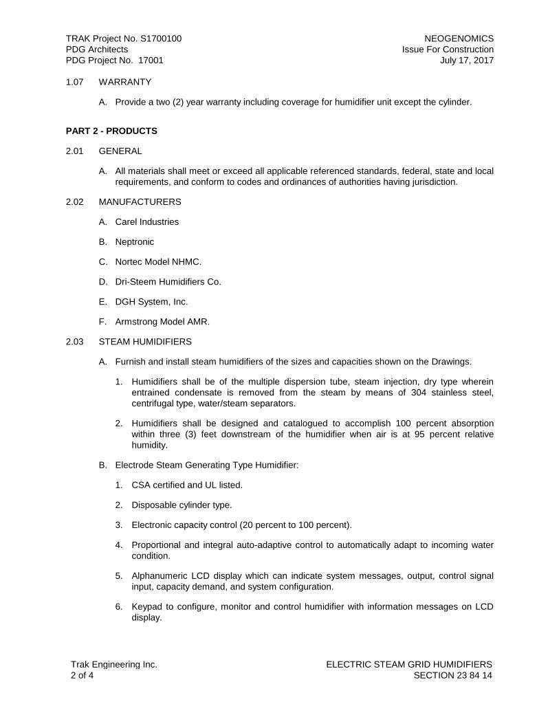
TRAK Project No. S1700100 NEOGENOMICS
PDG Architects Issue For Construction
PDG Project No. 17001 July 17, 2017
Trak Engineering Inc. ELECTRIC STEAM GRID HUMIDIFIERS
2 of 4 SECTION 23 84 14
1.07 WARRANTY
A. Provide a two (2) year warranty including coverage for humidifier unit except the cylinder.
PART 2 - PRODUCTS
2.01 GENERAL
A. All materials shall meet or exceed all applicable referenced standards, federal, state and local
requirements, and conform to codes and ordinances of authorities having jurisdiction.
2.02 MANUFACTURERS
A. Carel Industries
B. Neptronic
C. Nortec Model NHMC.
D. Dri-Steem Humidifiers Co.
E. DGH System, Inc.
F. Armstrong Model AMR.
2.03 STEAM HUMIDIFIERS
A. Furnish and install steam humidifiers of the sizes and capacities shown on the Drawings.
1. Humidifiers shall be of the multiple dispersion tube, steam injection, dry type wherein
entrained condensate is removed from the steam by means of 304 stainless steel,
centrifugal type, water/steam separators.
2. Humidifiers shall be designed and catalogued to accomplish 100 percent absorption
within three (3) feet downstream of the humidifier when air is at 95 percent relative
humidity.
B. Electrode Steam Generating Type Humidifier:
1. CSA certified and UL listed.
2. Disposable cylinder type.
3. Electronic capacity control (20 percent to 100 percent).
4. Proportional and integral auto-adaptive control to automatically adapt to incoming water
condition.
5. Alphanumeric LCD display which can indicate system messages, output, control signal
input, capacity demand, and system configuration.
6. Keypad to configure, monitor and control humidifier with information messages on LCD
display.

TRAK Project No. S1700100 NEOGENOMICS
PDG Architects Issue For Construction
PDG Project No. 17001 July 17, 2017
Trak Engineering Inc. ELECTRIC STEAM GRID HUMIDIFIERS
3 of 4 SECTION 23 84 14
7. Self-diagnostic controls on start-up and during operation shall prevent unsafe operation of
the unit.
8. Solenoid control of supply and drain water.
9. Automatic self-help feature that can clean obstruction from the drain valve when needed.
10. Automatic off-season shutdown that will completely drain the cylinder during prolonged off
periods and restart automatically on a call for humidity.
11. Full front access.
12. Constant Volume Control System: The humidifier shall be controlled by a humidistat,
airflow proving switch and high limit control that automatically shuts humidifier down when
the humidity level in the duct increases above 80 percent to 85 percent relative humidity.
Prevents wetting of the ductwork.
13. Variable Volume Control System: The humidifier shall be controlled by a humidistat,
airflow proving switch and modulating high limit control that will automatically reduce the
output capacity of the humidifier when the humidity level in the duct increases above 80
percent to 85 percent relative humidity. Prevents wetting of ductwork when airflow is
decreased.
14. Dual cylinder units shall have dual control circuits for complete control of each cylinder
and safety.
15. Steam distributor with condensate separator.
16. Remote message indication capability to indicate normal operation, change cylinder and
shutdown shall be standard.
17. Cal-rod heater element electric humidifiers not acceptable.
2.04 ACCESSORIES
A. Supply and install the following accessories in accordance with the manufacturer's
recommendation. Accessories based on Nortec Model NHMC.
1. 132-9203: Duct mounted pressure differential switch for air proving interlock.
2. 146-9321 through 146-9330: Proportional modulating control. Allows full modulating
control of humidifiers by varying signals from control systems supplied by others. Most
variable DC voltage, resistance and current signals can be accommodated.
3. 132-9505: Inline water filter for supply water.
4. 146-9533: Fill cup extension kit for NH-005 through NH-030. Required when duct static
and steam line resistance exceeds standard unit limitations.
5. 132-8810: Steam hose 7/8 inch ID for ASD and BSD type steam distributors used with
NH-005 through NH-030 units.
6. 132-8840: Condensate return hose 3/8-inch ID. Used with all units.

TRAK Project No. S1700100 NEOGENOMICS
PDG Architects Issue For Construction
PDG Project No. 17001 July 17, 2017
Trak Engineering Inc. ELECTRIC STEAM GRID HUMIDIFIERS
4 of 4 SECTION 23 84 14
7. 146-9525 and 146-9529: Remote service indicator package provides an audible and
visual indication remotely from the humidifier when any service code appears.
8. 146-9522: Low temperature protection. Activates humidifier independent of humidistat if
internal temperature falls below set point. Two (2) required for NH-150 and NH-200.
9. High limit stat to deactivate steam control valve when the high limit is 90 percent or
higher.
10. Provide a building automation system (BAS) interface card to receive signals from the
BAS for controlling the control valve of each humidifier.
PART 3 - EXECUTION
3.01 INSTALLATION
A. Installation shall meet or exceed all applicable federal, state and local requirements,
referenced standards and conform to codes and ordinances of authorities having jurisdiction.
B. All installation shall be in accordance with manufacturer’s published recommendations.
C. Install in accordance with ARI 630.
D. Provide galvanized steel rods to support distribution manifolds and mount in air system
plenums.
E. Connect outlet of unit to drain piping. Provide gate valve.
F. Install cold water supply of ¼-inch type K soft copper tubing with shutoff cock and 7/8 inch
drain line. Pipe drain to nearest floor drain ensuring air gap is incorporated per manufacturer's
instructions.
G. Mount airflow switch and tubing.
H. Install unit in duct with at least six (6) feet of straight run downstream of humidifier for steam
to be absorbed into the air stream. Provide the minimum number of dispersion tubes
(manifold) to achieve complete absorption in the short run.
3.02 TESTING
A. Operate humidifiers only when airflow is proven.
B. Start-up by a factory trained technician.
END OF SECTION 23 84 14