Embed Size (px)
Citation preview
•
Varactor Diode Applications By DONALD E. LANCASTER
These special semiconductor diodes, which operate as high-"Q"
e lectron ically v ari able capacitors, are find ing incre as ing
uses in a.f .c. circuits, FM modulators, harmonic generators,
and parametric amplifiers over a wide range of frequencies.
WHE;\'EVEH any /HI semiconductor junction is reyersed-biased, a depletion layer is formed in which there are no excess electrons or holes. No con<luction
takes place in this region. As the reverse hias varies, so does this depletion layer, the layer becoming thicker with increasing reYerse hias. The net effect is a high "Q," electronicall�· ,·ariable capacitor. \\'henever junction characteristics are opli111ized to yield this variable capacitance effect, a Y;1ractor diode results.
Due to their remarkable properties, varactor diodes now find extensi,·e use everywhere from the audio frequencies to the outer reaches of the extreme microwave frequencies. A varactor is a non-microphonic, comp;1ct, electronically variable capacitor whose capacitance can be rea<lily change<! at a high rate of speed. It can directly frequency-modulate a signal. It has a non-linear capacitance characteristic, allowing ,·,1ractors to serve as harmonic generators and parametric amplifiers. :\lost important, it is a reactance and not a resistance. Because of this, it is nearly lossless and essentially noiseless. Varactors are onlv a fraction of the size of conventional rnechanieall�· variable
'capacitors yet perform many tasks far
better. Commercially available varactors are amazing!�· diverse.
They range in price from a little over a dollar each for a.f.l·. v;iractors intended for FM receivers to exotic matched sets of parametric amplifier diodes costing thousands of dollars a pair. Low-frequency ,·aractors are available with capacitances as high as .002 microfarad; some microwave devices have a 111axim11n1 capacitance of only 0.4 picofarad. The power-handling capability ranges from 100 milliwatts or so for the small
June, 1966
varactors to stud-mounted versions that can accept over a hundred watts of input r.f. power. Some are strictly lowvoltage units ha\'ing a breakdown \'(Jltage in the reverse direction of uni�· 6 volts, "vhile other, high-\"!Jltage, units may be rated as high as - 300 volts and may have a maximum capacitance ratio on the order of 20: I or higher.
Varactor Ope rat io11 A varactor is alwnys operated so111ewl1cre between forward
breako,·er an<l re\'erse breakdown. As the reverse bias incre;1ses, the junction capacitnnce clccrcascs, !Jiit not in a linear manner. l\lany varadors will lian· tl1Pir .i1111ction capacitance var�· inversely as the square root of the ren•rse bias. This nonlinearity is a two-edged S\\'ord. It 111t•ans that bias-shaping circuitry is required to obtain large linear capacitance t;.1·
voltage control regions. This is highly desirable for frequency modulators and receiver-tuning applications. On the other hand, the two most i111porta11t ,·arador applications-frequency multiplication and parametric amplification-11111s/ have a non-linear capacitanl'c i.;s \'l>ltage characteristic. Both these applications are fundanwntally in1possihle in a linear, time-iin·;niant system.
The depletion la�·er is tllPn the dielectric ol a capacitor. As such, the varactor has a capacitance \'alue and a "Q." Both are determined in the C011\'l'11tional niannPr, the capal'itance being a function of the _junction area, the thickness of the depletion layer (as determinPd b�· the reverse bias), and the <lielectric constant. "()" is defined as the ratio of rc;lctance to resistance at a given frec111enc�', To obtain high''()," very low leakage is required. Because of this, silicon is used exdusively
43
www.americanradiohistorv.com
+0.6V (SILICON)
- R EYE.ASE FORWARD -
0
SIAS
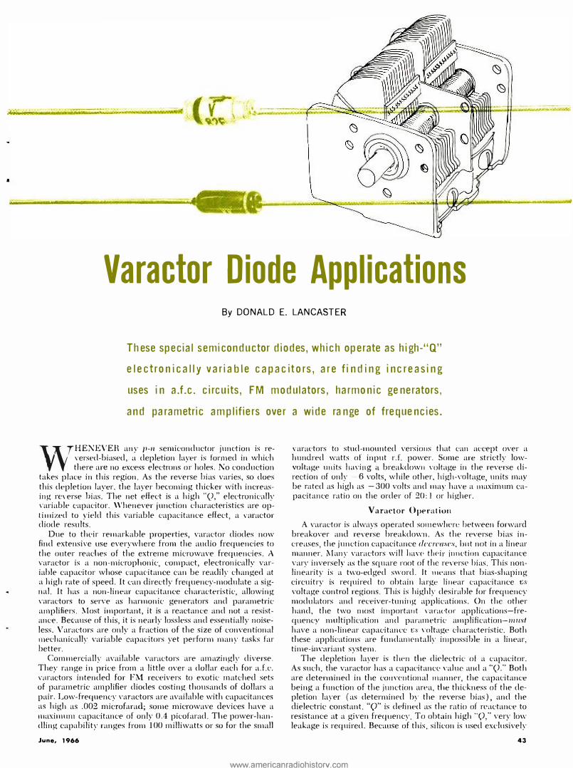
Fig. 1. Voroctor capacitance and ''Q" vary with bias voltage.
Tobie 1. A directory of manufacturers of voroctor diodes.
A =General-purpose. Jow-trequcncr control varactors. B =High eapU{'itancc. low-rrcquenc-y ntractors ( 68 pF or more 1. C = lli�h-power. low-frequency var:H'tors 1 1 watt or more 1. D= lligh-powcr, high-frequency \:tractors ( 1 watt or more; I 00 :\lllz and
higher I. E= :'\Iicrowave devices I l gigaherH and higher 1 .
44
GENERAL PURPOSE
(Al HIGH
CAPACITANCE
(Bl POWER
(Cl U.H.F.
POWER
(Dl MICROWAVE
(E) Fig. 2. Various types of varoctor packages ore shown here.
for all ,·aractors, except for a few gallium-arsenide micro"·ave dedces. The finite "Q" in1plies a loss or a resistive component. This occurs due to the bulk resistivitv of the semil'<mductor and appears as a small series resist,;nce.
A figure of merit of any \'aractor is its c11t-otf frcc111e11cu. This is the frequencv at which ''Q"= l. Put mathematically, "Q"=X/H= 1/2-;-;fCH and f.111-ntt= 1/2.-;-;RC where /=frequency in Hz, C = capacitance in farads, and R =series resistance in ohms for some specified bias value.
Low-frequency "()'s" are at least 50, typically 200 to 400 for many units. M,111y microwave varactors have "Q's" so high th ey ca1111ot be readilv measured. Some manufacturers guarantee "(_)'s" of several thousand.
Fig. l shows how capacitance and "Q" vary with changing re,·erse bias. The junctio11 capacitance tends to hecon1e i11-fi11itely grl'at at the forward breakover voltage, for here the depletion layer approad1Ps zero thickness. U11fortt111at1·ly, the j11nctio11 is conducting heavil�· at this point and has ceased being a capacitor. BPcause of this, the useful "Q" rapidly din1inishes as forward breakover is <lpproached. Obviously, if reverse breakdown is L'\'er reached, tl1e "()"' will also suddenly ,·,mish. The gre<lter the reverse bias, the greater the "Q" and the sn1aller the capacitance.
The choice of a reverse-bias operating point depc11ds upon the application. For n1axirnum capacitance swing, the varactor is normally biased halfway bet\\·een zero and a value safely under re,·t·rsc breakdo\\'11. For maxin1111n C<lpacita11ce c/1(111ge and greatest 11011-li11c<1rity, the ,·aractor is biased near the fonvard regio11. 111 fact, so111e harmonic 11ll1ltipliers actuall\· are 1110111cntarily drive1 1 into fo1ward conduction briefly each cvde to produce stro11g harmonics. Operation at zero bias has an alh-antagc in many circnits-110 cl.c. bias source is required. Finally, for 111axi1m11n "()" and greatest li1warity, the varactor can he biased well out 011 the curve, perhaps within a fe\\· volts of reverse breakdown.
The actual biasing techniques will becon1e apparent as we discuss applications. Since the var;1dor is al\\·a,·s operating in the rt'!;C'r.1·c'-bias region, 11egligiblc current, and hence, negligible hias po\\'er arc required. In this sc11se, a var,1clor is an extreme],· "high-gain" de,·ice, providing 111any control functions with rniJ,· a few 111 icrowatts of control power.
\\'here a d.c. bias is used, a stable reference source 11111st be obtained. If not, the j11nclio11 capacitance will faithfull,· follow anv drift or 11oise present "·ith the bias source. :\ zener diode is often empl<> > 'ed in order to prn,·ide a stable reference s011rce whl'n this is required.
Types of Yaractors There are five basic types of varactors, each with a funda
mentally different package. These are sho\\'n in Table l a11d Fig. 2. The ordi11ary diode package of Fig. 2A finds 11sf' for general-purpose, low-power, low-frequency ,·,uactors. These are usually low-cost de\'ices. rated at a few hundred milli\\ 'atts of power dissipation and ha,·ing j1t11ction capacitances
ELECTRONICS WORLD
www.americanradiohistorv.com
between l and 100 pf. These are used for any frequency where case and lead stra�· inductan<:e and capacitance are not important. whid1 usuall�· restricts their use to under .500 MHz. For sonie low-frequenc�· applications, more junction capacitance is required tha11 will fit in this package. To increase junction capacitance, either a larger junction or multiple junctions may be employed. Both techniques find use. This results i11 the "fat .. paekagl' of Fig. 2B. These devices range from 68 to 2000 pF and go as high as one or two watts of dissipation. Their main 11se is i11 low-frequency applications, such as audio phase shifters, A\I broadcast-hand applications, a11d delay lines.
The dissipation rati11g of any varactor is simply how much heat it can safe!,· dissipate. In an ordinary diode, substantial heat is produced ouly in the forward-biased and reversebreakdown regions. This heat is determined by multiplying the diode rnltagt· by th<' d.c. diode current, produl'ing the internal heat loss in watts. But no <l.c. current can How in a reverse-biased varactor (except for a trivial leakage current measured in nanoamperes). This is not true of an a.c:. signal, since it will readily travel through the junction capacitance and series resistance of the reverse-biased varactor. The a.c. current tra\'eli11g through the series resistance produces the heat loss that is the basis for the dissipation rating of the diode. The loss is gh·e11 J,,· f"R. where I is the instantaneous a.c. sig-11al curre11t and R, is the equivalent series resistance. The peak values of this particular power can be substantial in some cases.
For applications where high r.f. signal levels are a problem, the power varac:tor package of Fig. 2C finds use. Some of these power ,·aractors are rated at 25 watts and can easily handle r.f. power inputs of 100 watts. These are important in high-power multiplier chains, v.h.f. transmitters, and u.h.f. frequency multipliers. The practical upper frequency limit of this package is about 500 l\!Hz of r.f. input. He<ltsinking is usually prodded hy bolting the varactor to an aluminum or copper plate of reasonable size.
Above .500 MHz, the power \'aractor has to be streamlined to eli111inate stray capacitance, residual inductance, and other parasiti<:s, resulting in the u.h.f. power varactor package of Fig. 2D.
for microwave work, the least amount of circuit stravs can clrasti<:alli: alter performance. Lead inductances of 5
. nano
henrys <:an be intolerable, as can 0.1 pF of capacitance. Thus, the microwave "package" of Fig. 2E is not a package at all hut merely a means of protecting the semiconductor and making contact with the circuit. These devices are used exclusively in stripline and waveguide circuitry. Some varactors ha\'e cut-off frequencies in excess of 500 GHz and find use at frequencies of 80 to 100 GHz. These varactors are truly tiuysome will fit in an J�-inch cube with room to spare.
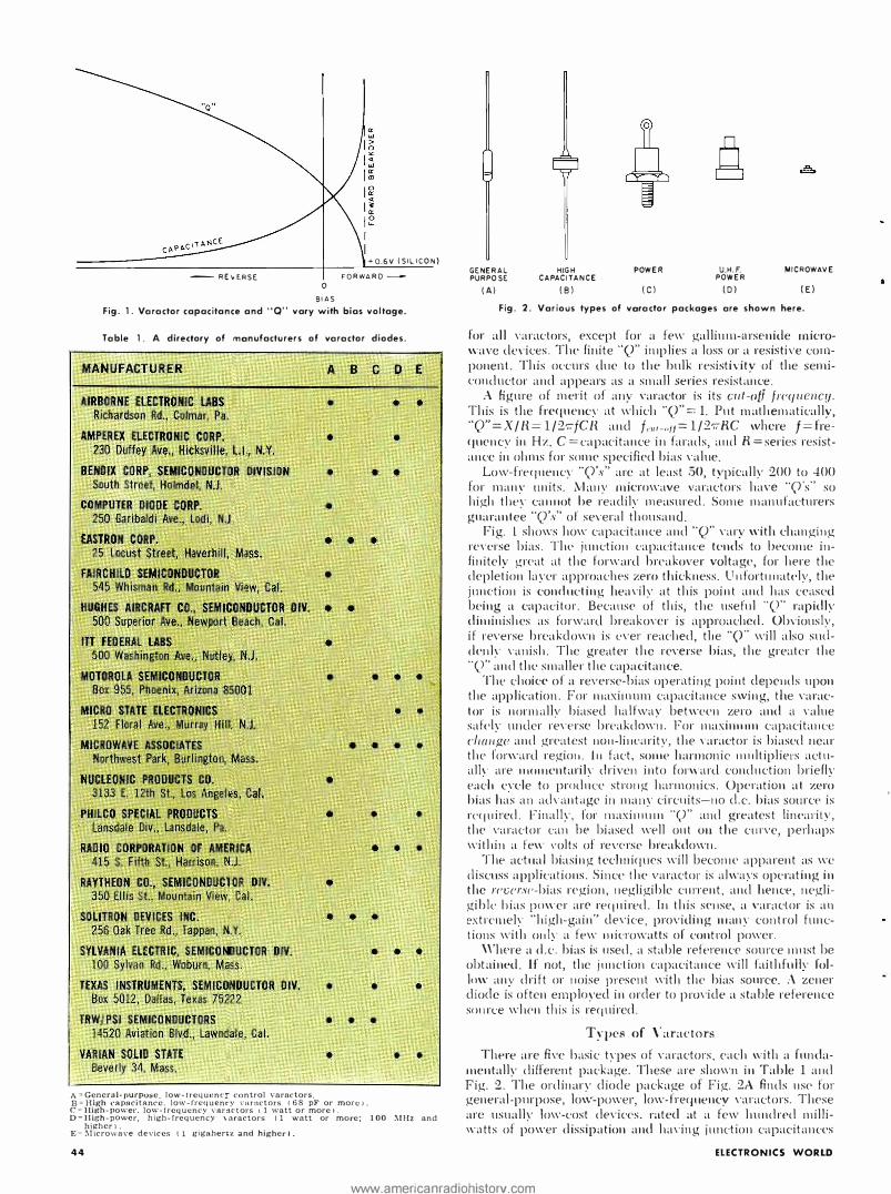
Circuit App1ications One obvious applil'ation ('Onsists of using a varactor as a
replacement for a c;o11ve11tional variable capacitor in a reso-11ant circuit, as shown in Fig. 3. To allow proper biasing, a blocking capacitor ( C) is aclded in series with the varactor. Biasing is by way of a high-value resistor and an r.f. bypass. As the d.c. bias on the varac:tor is changed, the depletion layer capacitance changes, which in turn changes the resonant frequency. If capa<:itor C in Fig. 3B is much larger than the j11nction capacitance, the series equivalent capacitance will essentially be that of the varactor itself.
There is a defect in this simple circuit. At any instant, the varactor sees a voltage that is the sum of the instantaneous signal and the d.c. bias value. If the signal is quite small, this is immaterial. But if the signal is large, it will itself bias the varactor differently on positive and negative cycles and cause severe distortion. This is eliminated bv the balanced varactor circuit of Fig. 3C. Here, two varactor� are used back to hack. As the signal swings positive, it decreases the capacitance of
June, 1966-
(A) CONV ENTIONAL RESONANT· C I R CUIT
-BIAS
(Bl SINGLE VAR ACTOR
-BIAS
-SIAS
(C) LOW-DISTORTION BALANCED ID) RESTRICTED-RANGE BALANCED CIRCUIT CIRCUIT
Fig. 3. The use of varactors in various tank circuits.
one varac:tor and increases the c:apadtam·e of the other ont'. The sum of the two series ('apacitors remains nearly constant, determined almost entirely by the bias ancl not the signal. Note that two series rnractors have only half the junction capaeit;111ce of a single unit.
Sometimes it is desirable to just trim a resonant circuit instead of permitting the varactor to assume full frequency control. A shunt capacitor may be added as in Fig. :JD to gi\'e an\' desired control range. The ratios of shunt to junction capacitance determine the swing the varactor can produce.
The circuit in Fig. 3C is usecl for radio-receiver tuning. For a conventional AM recei\'er, the 36.5-pF tuning capacitor is replaced by two 700-pF varactors in the balanced connection. A d.c. source and potentiometer provide the tuning. In more elaborate circuits, a saw-tooth signal may be used for tuning, producing either a signal-seeking tuner or a spectrum analyzer, depending upon the rest of the circuit. Obvious advantages of this circuit are mechanical stability, small size, and ease of remote control.
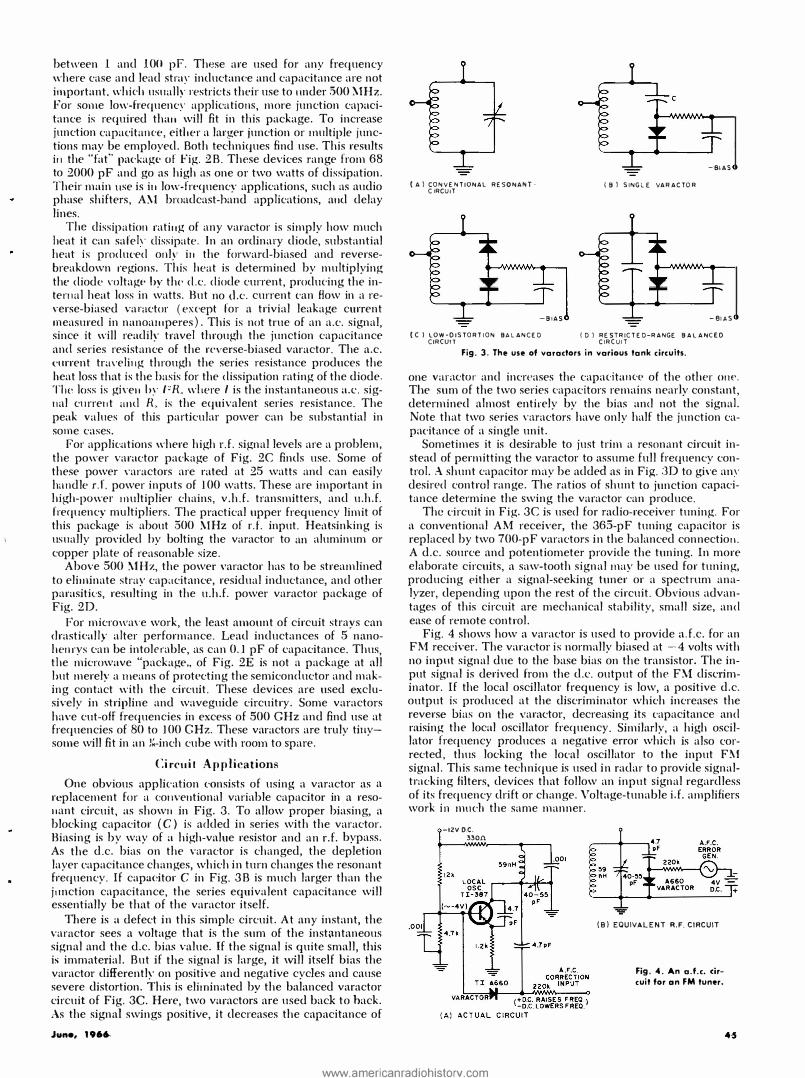
Fig. 4 shows how a varactor is used to provide a.f.c. for an FM receiver. The varactor is normally biased at -4 volts with no input signal due to the base bias on the transistor. The input signal is derived from the d.c. output of the FM discriminator. If the local oscillator frequency is low, a positive d.c. output is produced at the discriminator which increases the reverse bias on the varactor, decreasing its capacitance and raising the local oscillator frequency. Similarly, a high oscillator frequency produces a negative error which is also corrected, thus locking the local oscillator to the input F!\1 signal. This same technique is used in radar to provide signaltrnc:king filters, devices that follow an input signal regardless of its frequency drift or change. Voltage-tunable i.f. amplifiers work in m11d1 the same manner.
-IZV O.C. 3301'.l.
(Bl EQUIVALENT R.F. CIRCUIT
Fig. -4. An a.f.c. cir
cuit for an FM tuner.
www.americanradiohistorv.com
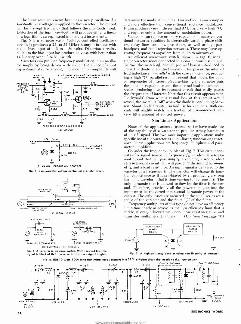
The basic resonant circuit becomes a sweep oscillator if a saw-tooth bias voltage is applied to the varactor. The output will be a swept frequency that follows the saw-tooth input. Distortion of the input saw-tooth will produce either a linear or a logarithmic sweep, useful in many test instruments.
Fig. 5 is a varactor v.c.o. (voltage-controlled oscillator) circuit. It produces a :2.'5- to 3.'5-}.IHz r.f. output in tune with a cl.c. bias input of - :2 to - 39 volts. Distortion circuitry added to the bias input has produced a v.c.o. with better than 1% linearitv over a :30% bandwidth.
\'aracto;·s can produce frecpiency modnlation in an oscillator simply by being driven with audio. The choice of shunt capacitance, d.c. bias point, and modulation amplitude will
Ll-17 T URNS #H W IRE OH CUIBION 1166-3-2 COIL FORM, TAPPEO AT �TURN.$
FREQUENCY CONTROL <>-4-W� •re ·�+12vo.c.
INPUT -2 TO-l9V o.c.
.01 � R.•. OUTPUT 2�-3�WH& 2V P-P
Uk
RFC vmr....--�'1 'l'�--''--�>--__,.-1n Jr-<>-ev o.c. :;i;. .Cl
RFc's ARE FERRITE BEAD CHOKES
(A) CIRCUIT
Uk (-39V)
39V ZENER IH4 7�4
S•�-(-_Z_T_.o_-_39_v_>_.., TO FREQUENCY CONTROL INPUT
0.1 240!\.
"F
\Bl MANUAi- FREQUENCY CONTROL. Fig. 5. Dual-varactor voltage-controlled oscillator circuit.
CAPACITOR - � �======
··� R F BYPASS c�:�
-=-+ � E
� ):'RFC
'\, R . F. fGNAL 2 VARACTOR
OC. BLOCKING; COAX TRANSMISSION LINE CAPAC I T OR
(A) ACTUAL CIRCUIT
CASE CAPACITANCE
PARALLEL RESONANT AT f1
JUNCTION CAPACITANCE
p LEAD
I ,� INDUCTANCE
SER IES RESONANT AT 11
(BJ EQUIVALENT R.F. CIRCUITS
Fig. 6. A varaclor microwave switch. With forward bias the signal is blocked !left); reverse bias passes signal (right).
determine the modulation index. This method is m11ch simpler and more effective than conventional reactance modulators. It also produces \'ery little residual A�!, has a very high "Q," and requires only a tiny amount of modulation power.
Varactors can replace ordinary capacitors in manv conventional networks, resulting in electrically variable phase shifters, delay lines, and low-pass filters, as well as higli-pass, bandpass, and band-rejection networks. These may have operating frequencies anywhere from audio to microwave.
An efficient microwave switch, shown in Fig. 6, uses a single varactor series-connected in a coaxial transmission line. To turn the switch off, enough foncard bias is introd11ced to cause the diode to conduct heavily. This places the internal lead inductance in parallel with the case capacitance, producing a high "Q" parallel-resonant circuit that blocks the band of frequencies of interest. Rl'versc-biasing the varactor puts the junction eapacitance and the internal lead inductance in Sl'ri<:s, producing a series-resonant circuit that easily passes the frequencies of interest. Note that this circuit appears to be "backwards" from what a casual look at this circuit wou Id reveal; the switch is "off" when the diode is conducting heaviest. Shunt diode circuits also find use for varactors. Both circuits will readily switch in a fraction of a nanosecond with very little amount of control power.
Non-Linear Applications None of the applications discussed so far have made use
of the capability of a varactor to produce strong harmonics of an r.f. signal. The two most important applications make specific use of the varactor as a non-linear, time-varying reactance. These applications are frequency multipliers and parametric amplifiers.
Consider the frequency doubler of Fig. 7. This circuit consists of a signal source at frequency f i, an ideal series-resonant circuit that will pass only f 1, a varactor, a second ideal series-resonant circuit that will pass on/!f the second harmonic off 1, and a load resistance. An input signal is delivered to the varactor at a frequency f1. The varactor will change its junction eapacitance as it is self-biased by f1, producing a strong harmonic waveform that is time-varying to the tune off 1. Tlie onlv harmonic that is allowed to flow bv the filter is the second. Therefore, practically all the pow�r that goes into the input must be converted into second harmonic power at the output. The only losses are incurred in the small series resistance of the varactor and the finite "Q" of the filters.
Frequency multipliers of this type do not have an efficiency limitation nearly as severe as the 1/ 11 efficiency limit that is rarelv if ever achieved with non-linear resistance tube and tran;i�tor m11l;ipliers. Doublers ( Co11ti1111cd 011 ]loge 70)
1, SOURCE
IDEAL FILTEA
PASSES
ONLY f1
IDEAL FILTER
PASSES
ONLY 2f1
2f1 LOAD
Fig. 7. A high-efficiency doubler using non-linearity of varaclor.
Fig. 8. This 10-watt, 1000-MHz transmitter uses varactors in a 22 % efficient circuit that needs no d.c. input power.
.8-12 pF
45W, 83MHz
INPUT z '50.0.
46
.8-12pF
(TRIPLE RI
. 8-12pF .8-12pF
lDOUBLERI
2BW, 250MH z
www.americanradiohistorv.com
CAVITY 500 MHz CAVITY IOOOMHz
r-----1 I I I
�-----, 1--<11,___..__.....,._..�__.� I I I L
17W, 500MHZ
l DOUBLER}
I I
--ij IM.0. 6
IOW, IOOOMHz OUTPUT
z ,50.0.
ELECTRONICS WORLD
SPRING EDITION
Now Available-The all-new Spring 1966 Edition of ELECTRONIC EXPERIMENTER'S HANDBOOK! An· other big package of over 30 fascinating do·ityourself construction projects for:
Amateur Radio Automotive Electronics Photography Hifi/Stereo & Audio Test Equipment Short-Wave Listening
You'll build such valuable units as ... a super photo flash ... a simple auto light minder ... a transistor FM multiplexer ... an electric fence charger ... and a self-regulating lighting controller.
Each has complete, easy-to-follow schematics, parts lists and how-to instructions that guarantee you perfect finished products! Plus-dozens of prates· sional pointers, tips and techniques to increase your overall electronics skills and proficiency. In all, more than 148 pages of challenging projects that will deliver hour after hour of sheer fun ... and provide you with economically-built, useful items (to keep, or sell for a profit) after you've finished.
Make sure you receive your copy of this $12 5 valuable handbook. Fill in !lie coupon and --mail
�10�0:�:�. GOLO-EMBOSSEO 'II· LEATHERFLEX·BOUNO EDIT ION
. .. . just $3.00 postpaid ·
�
This deluxe edition is
1_ . �'I a p e r m a n e n t, h a n d· somely-bound callee
' --� tor's item that belongs in your electronics Ii· brary! Check appropriate box on coupon. -- ---- ..
ZIFF-DAVIS SERVICE DIVISION, Dept. EEH 589 Broadway, New York , N.Y. 10012 COUNT ME IN . .. for a copy of the Spring 1966 ELECTRONIC EXPERIMENTER'S HAND· BOOK as I've indicated:
0 $1.25 enclosed, plus 15¢ for shipping and handling. Send me the regular edi· lion. ($1.50 for orders outside U.S.A.)
0 $3.00 enclosed. Send me the Deluxe Leatherflex-Bound edition, postpaid. ($3.75 for orders outside U.S.A.) Allow three additional weeks for delivery.
name please print EW-66
address
city state zip code
• • PAYMENT MUST BE ENCLOSED WITH ORDER • .I 70
Varactor Diode Aoplications (Co11ti1111cd from page 46)
with o\'er 90% efficiency an cl .")0% efficient o<:tuplers are readily achie,·cd and reCj11ire no power except the input signal. Any order harmonic may be produced by proper filtering. By allowing certain other harmonics to flow and then multiply each other, efficiencies may be markedly increased.
The present practical limitations of this technique arc about 2.'5 watts of r.f. output at l GHz and 2.5 watts at I 0 GHz. Useful harmonic power ma,· he obtained at 100 GHz in special C'ir('11its.
Fig. 8 is a typical circuit. It is a 1-CHz. I 0-watt transmitter driven from a .f.),,·att, 83-.\ I Hz somce. This gi\'es a 22% efficiency after a multiplicatio11 of twelve. The three \'aractors have ;1 total cost of around $12.5. This is consiclerah],· more economical than any other prt'sP11t solid-state technique. Note that no d.c. power is required by the circuit as the v;1ractors derive a self-bias from the r.f. input. The size, power, and reliahilitv advantage over tube circuits is oh\'ious.
This type of circuit finds use in '"Id. and 11.ld. solid-state transmitters ;mcl signal sources. A second type of circuit uses higher order multiplication to allow a low-frequency (2.5 to .'50 �!Hz) crystal to produce a stable reference microwave frequency, perhaps at IO or 2-1 GHz. This is often usecl to phase-lock klystrons, backward-wave oscillators, an<l other tubes, producing substantial, precisely controlled microwave power.
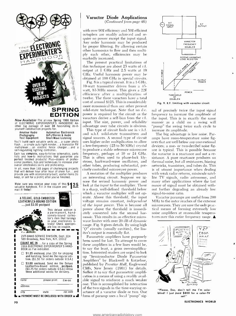
A mutation of the multiplier produces an interesting circuit. Suppose we ignore the second hannonk power an<l look at the input to the multiplier. There is a sharp, well-defined thrcsholcl below which a varacto1· multiplier \\'ill not operate. Above this threshold, thf' input \'oltage remains constant, i11dcpc11dc11t of t!tc input 1w1ccr. This is because all power above the threshold is immediately converted into the secoml har-111011ic. This results in an effective microwave limiter with over 20 dB nf dynamic range. Fig. 9 gives details. By using high "Q" circuits (usually ca\'ities), the limiter's output is essentially flat.
Parametric amplifiers have purposely been saved for last. To attempt to cove1· these amplifiers in a few lines would be, to say the least, a gross oversimplification. Tuterested readers are urged to look up "Semiconductor Diode Parainf'tric Amplifiers" by Blackwell & Kotzebue, published by Prenticc Hall, Englewood Cliffs, New Jersey ( 1961) for details. Suffice it to say that parametric amplification is a means of using a rf'aclily a\·ailable signal to reinforce a much weaker one. This is accomplished by interaction of the two signals in the time-varying reactance of a varactor diode or two. One form of paramp uses a local ·'pump" sig-
www.americanradiohistorv.com
R.F.
SIGNAL INPUT
VARACTOR
FREQUENCY
DOUBLER
R.F OUTPUT
SECOND H A RMONIC LOAD RESISTOR
�--.,L----- OUTPUT
I THRESHOLD
OF
OOUBLER
POWER
POWER
Fig. 9. R.F. limiting with varactor circuit.
nal of precise]\' twice the input signal frecj11ency to increase the ampli tmlc of the input. This is in exactly the same manner as a child on a swing will "pump" the swing twice each cycle to increase its amplit11cle.
The big advantage is low noise. Paramps have room-temperature noise figures that are well below anv conventional devices; a one- or two-de�ihel noise flgme is typical. This is possible because the varactor is a reactance and not a resistance. A pure reactance produces no thermal noise, hut all resistances, biasing networks, transistors, nnd tubes do. This is of utmost importance when dt>aling with weak radar returns, miniscule satellite TV signals, radio astronomy, and many other applications where the last ounce of signal must be obtained without fmther degrading an already low signal-to-noise ratio.
Varactor paramps are useful from :200 !\!Hz to the outer reaches of the extreme microwaves. They are now the only practical means of forming extremely low noise amplifiers at reasonable temperatmes m·er this entire frcqnenc\· rangt>. A
"Please, Doc, don't tell me I'm color blind! I just paid $800 for a color-TV
set!"
ELECTRONICS WORLD