Embed Size (px)
Citation preview
READ AND SAVE THESE INSTRUCTIONS
VAPORSTREAMModels VLC and VLDI
ELECTRIC STEAM HUMIDIFIERS
Installation Instructionsand
Maintenance OperationsManual
®
For Toll-Free Technical Support,Call 1-800-328-4447
CUL LISTEDUL LISTED

2
TO THE PURCHASER AND THE INSTALLERThank you for purchasing VAPORSTREAM® Model VLC equipment. We have designed and built this equipment to giveyou total satisfaction and many years of trouble-free service. Proper installation and operating practices will assure youof achieving that objective. We therefore urge you to become familiar with the contents of this manual.
This manual covers material for both VAPORSTREAM Model VLC and VAPORSTREAM Model VLDI humidifiers. Mostof the application material will apply to both units. When information differs for the two units, it will be noted as such.
DRI-STEEM Humidifier Company
VAPORSTREAM Models VLC and VLDI .............................. 3
Mechanical Specifications and Capacities .......................... 4
Mechanical Specifications .................................................... 5
VAPORSTREAM Model VLC AREA-TYPE Humidifier ......... 6
Mounting MethodsMounting Procedures .................................................. 7Electrical .................................................................... 8
Dispersion Tube Installation ................................................ 9
Optional Weather Cover ........................................................ 11Weather Cover Dimensions......................................... 12
RAPID-SORB® Assembly and InstallationHorizontal Duct Installation ......................................13Vertical Duct Installation ......................................... 14
Piping MethodsDrain Piping ................................................................ 15Make-up Water Piping ................................................. 15
Piping Diagrams: Steam, Water and Drain .......................... 16
Start-up Procedure ................................................................ 17
Operation ............................................................................... 17
Recommended Maintenance ................................................ 18
Trouble-Shooting Guide ....................................................... 18
Replacement Parts ................................................................ 19
Maintenance Service Record ................................................ 21
Two-Year Limited Warranty .................................................. 23
TABLE OF CONTENTS
3
VAPORSTREAM® MODELS VLC AND VLDI
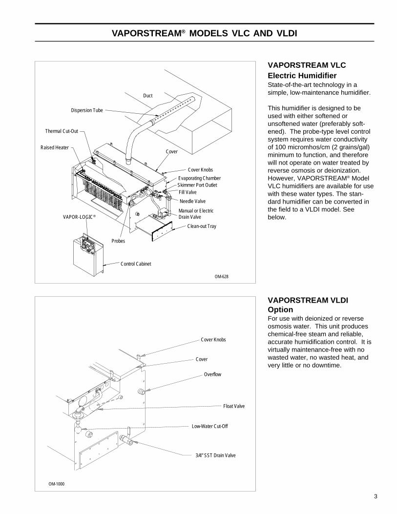
VAPORSTREAM VLCElectric HumidifierState-of-the-art technology in asimple, low-maintenance humidifier.
This humidifier is designed to beused with either softened orunsoftened water (preferably soft-ened). The probe-type level controlsystem requires water conductivityof 100 micromhos/cm (2 grains/gal)minimum to function, and thereforewill not operate on water treated byreverse osmosis or deionization.However, VAPORSTREAM® ModelVLC humidifiers are available for usewith these water types. The stan-dard humidifier can be converted inthe field to a VLDI model. Seebelow.
VAPORSTREAM VLDIOptionFor use with deionized or reverseosmosis water. This unit produceschemical-free steam and reliable,accurate humidification control. It isvirtually maintenance-free with nowasted water, no wasted heat, andvery little or no downtime.
OM-628
Control Cabinet
Probes
VAPOR-LOGIC®
Raised Heater
Dispersion Tube
Duct
Cover
Cover Knobs
Evaporating ChamberSkimmer Port OutletFill Valve
Needle Valve
Manual or ElectricDrain Valve
Clean-out Tray
Thermal Cut-Out
OM-1000
Cover Knobs
Cover
Overflow
Float Valve
Low-Water Cut-Off
3/4" SST Drain Valve
4
MECHANICAL SPECIFICATIONS AND CAPACITIES
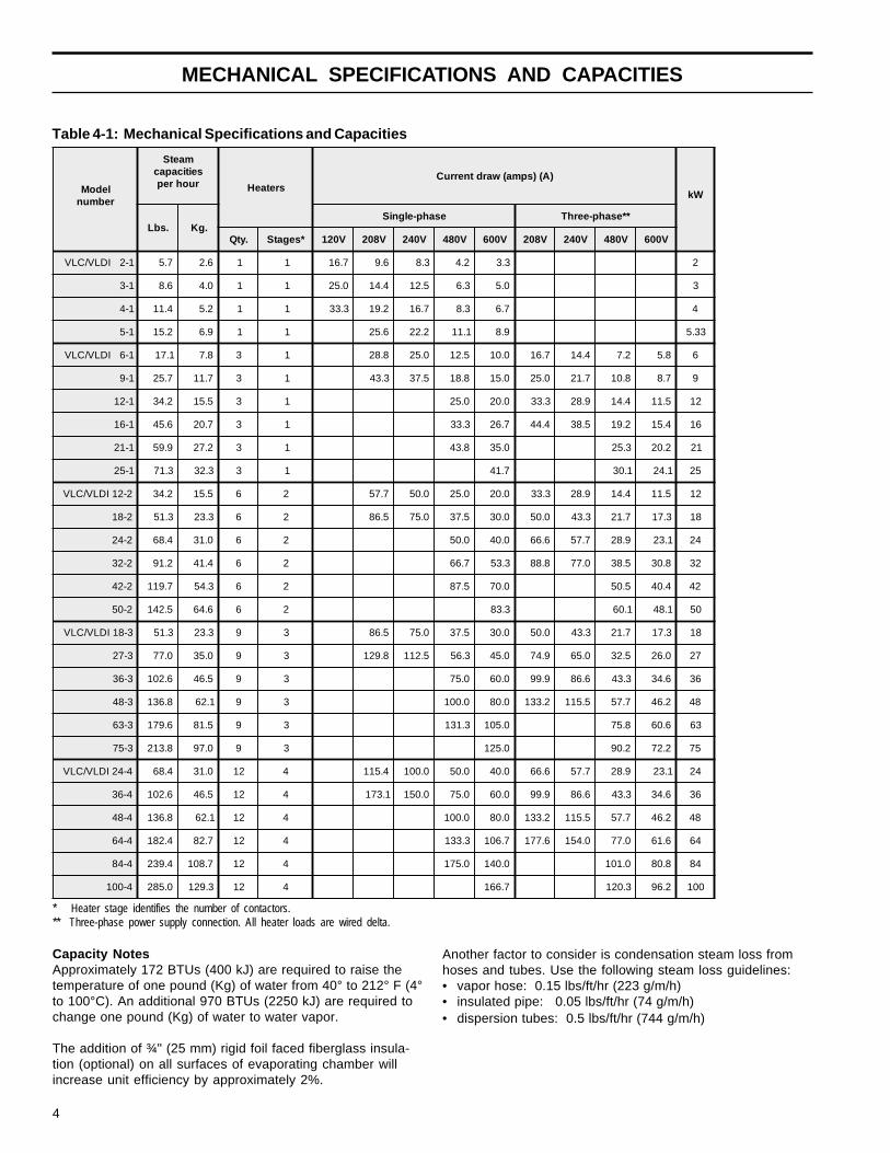
Capacity NotesApproximately 172 BTUs (400 kJ) are required to raise thetemperature of one pound (Kg) of water from 40° to 212° F (4°to 100°C). An additional 970 BTUs (2250 kJ) are required tochange one pound (Kg) of water to water vapor.
The addition of ¾" (25 mm) rigid foil faced fiberglass insula-tion (optional) on all surfaces of evaporating chamber willincrease unit efficiency by approximately 2%.
Another factor to consider is condensation steam loss fromhoses and tubes. Use the following steam loss guidelines:• vapor hose: 0.15 lbs/ft/hr (223 g/m/h)• insulated pipe: 0.05 lbs/ft/hr (74 g/m/h)• dispersion tubes: 0.5 lbs/ft/hr (744 g/m/h)
Table 4-1: Mechanical Specifications and Capacities
* Heater stage identifies the number of contactors.** Three-phase power supply connection. All heater loads are wired delta.
ledoMrebmun
maetSseiticapacruohrep sretaeH
)A()spma(wardtnerruC
Wk
.sbL .gKesahp-elgniS **esahp-eerhT
.ytQ *segatS V021 V802 V042 V084 V006 V802 V042 V084 V006
1-2IDLV/CLV 7.5 6.2 1 1 7.61 6.9 3.8 2.4 3.3 2
1-3 6.8 0.4 1 1 0.52 4.41 5.21 3.6 0.5 3
1-4 4.11 2.5 1 1 3.33 2.91 7.61 3.8 7.6 4
1-5 2.51 9.6 1 1 6.52 2.22 1.11 9.8 33.5
1-6IDLV/CLV 1.71 8.7 3 1 8.82 0.52 5.21 0.01 7.61 4.41 2.7 8.5 6
1-9 7.52 7.11 3 1 3.34 5.73 8.81 0.51 0.52 7.12 8.01 7.8 9
1-21 2.43 5.51 3 1 0.52 0.02 3.33 9.82 4.41 5.11 21
1-61 6.54 7.02 3 1 3.33 7.62 4.44 5.83 2.91 4.51 61
1-12 9.95 2.72 3 1 8.34 0.53 3.52 2.02 12
1-52 3.17 3.23 3 1 7.14 1.03 1.42 52
2-21IDLV/CLV 2.43 5.51 6 2 7.75 0.05 0.52 0.02 3.33 9.82 4.41 5.11 21
2-81 3.15 3.32 6 2 5.68 0.57 5.73 0.03 0.05 3.34 7.12 3.71 81
2-42 4.86 0.13 6 2 0.05 0.04 6.66 7.75 9.82 1.32 42
2-23 2.19 4.14 6 2 7.66 3.35 8.88 0.77 5.83 8.03 23
2-24 7.911 3.45 6 2 5.78 0.07 5.05 4.04 24
2-05 5.241 6.46 6 2 3.38 1.06 1.84 05
3-81IDLV/CLV 3.15 3.32 9 3 5.68 0.57 5.73 0.03 0.05 3.34 7.12 3.71 81
3-72 0.77 0.53 9 3 8.921 5.211 3.65 0.54 9.47 0.56 5.23 0.62 72
3-63 6.201 5.64 9 3 0.57 0.06 9.99 6.68 3.34 6.43 63
3-84 8.631 1.26 9 3 0.001 0.08 2.331 5.511 7.75 2.64 84
3-36 6.971 5.18 9 3 3.131 0.501 8.57 6.06 36
3-57 8.312 0.79 9 3 0.521 2.09 2.27 57
4-42IDLV/CLV 4.86 0.13 21 4 4.511 0.001 0.05 0.04 6.66 7.75 9.82 1.32 42
4-63 6.201 5.64 21 4 1.371 0.051 0.57 0.06 9.99 6.68 3.34 6.43 63
4-84 8.631 1.26 21 4 0.001 0.08 2.331 5.511 7.75 2.64 84
4-46 4.281 7.28 21 4 3.331 7.601 6.771 0.451 0.77 6.16 46
4-48 4.932 7.801 21 4 0.571 0.041 0.101 8.08 48
4-001 0.582 3.921 21 4 7.661 3.021 2.69 001
5
MECHANICAL SPECIFICATIONS
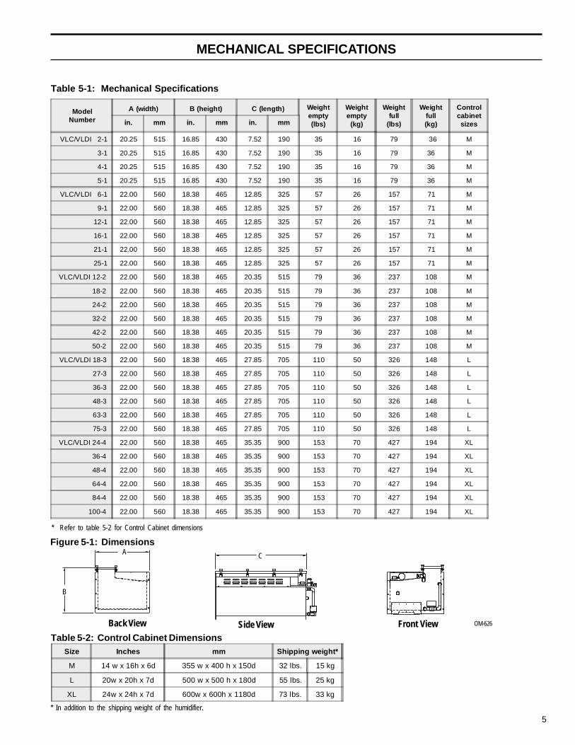
Table 5-1: Mechanical Specifications
Table 5-2: Control Cabinet Dimensions
* In addition to the shipping weight of the humidifier.
Figure 5-1: Dimensions
B
Back View
A
OM-626Front ViewSide View
C
* Refer to table 5-2 for Control Cabinet dimensions
ModelNumber
A (width) B (height) C (length) Weightempty(lbs)
Weightempty(kg)
Weightfull
(lbs)
Weightfull(kg)
Controlcabinetsizesin. mm in. mm in. mm
VLC/VLDI 2-1 20.25 515 16.85 430 7.52 190 35 16 79 36 M
3-1 20.25 515 16.85 430 7.52 190 35 16 79 36 M
4-1 20.25 515 16.85 430 7.52 190 35 16 79 36 M
5-1 20.25 515 16.85 430 7.52 190 35 16 79 36 M
VLC/VLDI 6-1 22.00 560 18.38 465 12.85 325 57 26 157 71 M
9-1 22.00 560 18.38 465 12.85 325 57 26 157 71 M
12-1 22.00 560 18.38 465 12.85 325 57 26 157 71 M
16-1 22.00 560 18.38 465 12.85 325 57 26 157 71 M
21-1 22.00 560 18.38 465 12.85 325 57 26 157 71 M
25-1 22.00 560 18.38 465 12.85 325 57 26 157 71 M
VLC/VLDI 12-2 22.00 560 18.38 465 20.35 515 79 36 237 108 M
18-2 22.00 560 18.38 465 20.35 515 79 36 237 108 M
24-2 22.00 560 18.38 465 20.35 515 79 36 237 108 M
32-2 22.00 560 18.38 465 20.35 515 79 36 237 108 M
42-2 22.00 560 18.38 465 20.35 515 79 36 237 108 M
50-2 22.00 560 18.38 465 20.35 515 79 36 237 108 M
VLC/VLDI 18-3 22.00 560 18.38 465 27.85 705 110 50 326 148 L
27-3 22.00 560 18.38 465 27.85 705 110 50 326 148 L
36-3 22.00 560 18.38 465 27.85 705 110 50 326 148 L
48-3 22.00 560 18.38 465 27.85 705 110 50 326 148 L
63-3 22.00 560 18.38 465 27.85 705 110 50 326 148 L
75-3 22.00 560 18.38 465 27.85 705 110 50 326 148 L
VLC/VLDI 24-4 22.00 560 18.38 465 35.35 900 153 70 427 194 XL
36-4 22.00 560 18.38 465 35.35 900 153 70 427 194 XL
48-4 22.00 560 18.38 465 35.35 900 153 70 427 194 XL
64-4 22.00 560 18.38 465 35.35 900 153 70 427 194 XL
84-4 22.00 560 18.38 465 35.35 900 153 70 427 194 XL
100-4 22.00 560 18.38 465 35.35 900 153 70 427 194 XL
Size Inches mm Shipping weight*
M 14 w x 16h x 6d 355 w x 400 h x 150d 32 lbs. 15 kg
L 20w x 20h x 7d 500 w x 500 h x 180d 55 lbs. 25 kg
XL 24w x 24h x 7d 600w x 600h x 1180d 73 lbs. 33 kg

6
VAPORSTREAM® MODEL VLC AREA-TYPE HUMIDIFIER
AREA-TYPE Humidifier ApplicationInformationThe operating characteristics of AREA-TYPE steamhumidifiers should be considered when selecting humidi-fier capacities and choosing mounting locations.
Steam discharge from the humidifier quickly cools andturns to visible, warm, microscopic drops or particles ofwater (fog) which are lighter than air.
Should this fog contact any solid surface (columns,beams, ceiling, pipes, etc.) before it disappears, it maycollect and drip, as water.
The greater the space relative humidity, the higher andfarther the "fog" will carry and rise in the space beforedisappearing.
The table at right states the vertical (rise), horizontal(throw), and width (spread) dimensions that can beexpected with the AREA-TYPE humidifiers.
To avoid steam impingement on surrounding areas, thesedimensions should be observed.
Note: Tank dimension "C," in figure 5-1 on page 5, mustbe at least 12.85" (325 mm) and output should not exceed285 lbs/hr (130 Kg/h).
Table: 6-1: Minimum Distance for Rise, Spread and Throw
OM-681Heaters
�
SteamChute �
�
Fan
Figure 6-1: Principle of OperationSteam created in the evaporating chamber (1) flows upthrough the chute (2), and is distributed into the space (3)via the fan.
Spacetemp.
SpaceRH
50lbs/hr
20kg/hr
100lbs/hr
45kg/hr
150lbs/hr
65kg/hr
200lbs/hr
90kg/hr
250lbs/hr
110kg/hr
285lbs/hr
130kg/hr
60° F16° C
30%
Rise 1 ft. 0.5 m 4 ft. 1.5 m 6 ft. 2.0 m 7 ft. 2.5 m 8 ft. 2.5 m 9 ft. 3.0 m
Spread 2 ft. 1.0 m 4 ft. 1.5 m 5 ft. 2.0 m 7 ft. 2.5 m 8 ft. 2.5 m 9 ft. 3.0 m
Throw 6 ft. 2.0 m 10 ft. 3.0 m 12 ft. 4.0 m 13 ft. 4.0 m 15 ft. 5.0 m 17 ft. 5.5 m
40%
Rise 1 ft. 0.5 m 4 ft. 1.5 m 6 ft. 2.0 m 8 ft. 2.5 m 9 ft. 3.0 m 10 ft. 3.0 m
Spread 2 ft. 1.0 m 4 ft. 1.5 m 5 ft. 2.0 m 7 ft. 2.5 m 9 ft. 3.0 m 10 ft. 3.0 m
Throw 6 ft. 2.0 m 10 ft. 3.0 m 12 ft. 4.0 m 14 ft. 4.5 m 16 ft. 5.0 m 18 ft. 5.5 m
50%
Rise 1 ft. 0.5 m 4 ft. 1.5 m 6 ft. 2.0 m 8 ft. 2.5 m 9 ft. 3.0 m 10 ft. 3.0 m
Spread 2.5 ft. 1.0 m 5 ft. 2.0 m 5 ft. 2.0 m 7 ft. 2.5 m 9 ft. 3.0 m 10 ft. 3.0 m
Throw 6 ft. 2.0 m 10 ft. 3.0 m 12 ft. 4.0 m 14 ft. 4.5 m 16 ft. 5.0 m 18 ft. 5.5 m
70° F21° C
30%
Rise 1 ft. 0.5 m 3 ft. 1.0 m 4 ft. 1.5 m 5 ft. 2.0 m 5 ft. 2.0 m 7 ft. 2.5 m
Spread 1.5 ft. 0.5 m 3 ft. 1.0 m 4 ft. 1.5 m 5 ft. 2.0 m 5 ft. 2.0 m 7 ft. 2.5 m
Throw 4 ft. 1.5 m 8 ft. 2.5 m 10 ft. 3.0 m 11 ft. 3.5 m 12 ft. 4.0 m 14 ft. 4.5 m
40%
Rise 1 ft. 0.5 m 3 ft. 1.0 m 4 ft. 1.5 m 5 ft. 2.0 m 6 ft. 2.0 m 7 ft. 2.5 m
Spread 2 ft. 1.0 m 3 ft. 1.0 m 4 ft. 1.5 m 5 ft. 2.0 m 6 ft. 2.0 m 7 ft. 2.5 m
Throw 4 ft. 1.5 m 8 ft. 2.5 m 11 ft. 3.5 m 12 ft. 4.0 m 13 ft. 4.0 m 15 ft. 5.0 m
50%
Rise 1 ft. 0.5 m 3 ft. 1.0 m 4 ft. 1.5 m 5 ft. 2.0 m 5 ft. 2.0 m 7 ft. 2.5 m
Spread 2 ft. 1.0 m 3 ft. 1.0 m 4 ft. 1.5 m 5 ft. 2.0 m 5 ft. 2.0 m 7 ft. 2.5 m
Throw 4 ft. 1.5 m 8 ft. 2.5 m 11 ft. 3.5 m 12 ft. 4.0 m 14 ft. 4.5 m 16 ft. 5.0 m

7
Figure 7-1: VLC Mounting Methods
1. Floor Stand Method 2. Trapeze Hanger Method 3. Wall Brackets Method
4. Mounting Unit Below DuctMounting humidifier 18" (460 mm) below duct isrecommended to facilitate cover removal.
Mounting ProceduresFor proper operation of the electrode probe water levelcontrol and the skimmer system, the humidifier must bemounted level in both directions.
Access,18" minimum (460 mm), for periodic removal ofthe top cover is recommended. The cover is removed forinspection and cleaning of the evaporating chamber. Inmost cases, scale that forms on the heating elementscontinuously flakes off as it forms and the loose scale
MOUNTING METHODS
OM-648
24 ¾"(630 mm)
Two-piece Escutcheon Platefastens to bottom of duct(duct omitted for clarity)
Cover of VAPORSTREAM®
Humidifier
OM-65
settles to the bottom. A clean-out tray on the floor of thetank may be removed periodically through the front clean-outopening. Allow space for withdrawal of the tray when install-ing the humidifier.
In some installations, an overflow drain pan may be neces-sary to prevent possible damage to flooring. This may becaused by a rapid or sudden drainage of the contents of thehumidifier. The drain pan must be connected to the sanitarywaste water system.
DRI-STEEMwall brackets(optional)2 required
A
Secure rods tooverhead construction
Angle or channelof size required
OM-647
Threaded rod ofsize required
Cleanout
Steam DispersionTube
Provide 18" (460 mm)min. clearance underduct for cover removalDRI-STEEM
support legs(optional)
OM-646
Clamp
Vapor Hose
Bottom of Duct
2 piece Escutcheon Plate
Cover of VAPORSTREAMHumidifier
18" min.(460 mm)
Cut hole in duct largeenough to allowpassage of hose clamp
OM-66
Steam DispersionTube
tinUsnoisnemiD
Arof)sehcnini(
snoisnemiDArof
)mmni(
retaeh3 91 084
retaeh6 91 084
retaeh9 03 067
retaeh21 63 519
8
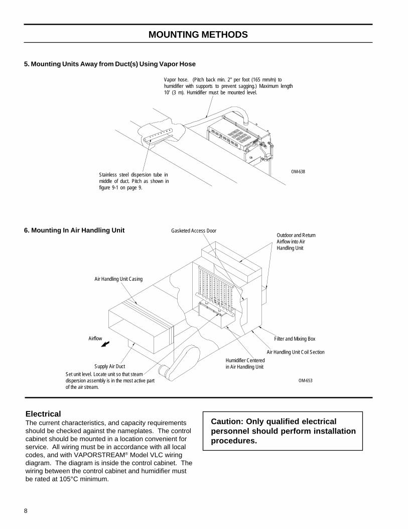
5. Mounting Units Away from Duct(s) Using Vapor Hose
MOUNTING METHODS
ElectricalThe current characteristics, and capacity requirementsshould be checked against the nameplates. The controlcabinet should be mounted in a location convenient forservice. All wiring must be in accordance with all localcodes, and with VAPORSTREAM® Model VLC wiringdiagram. The diagram is inside the control cabinet. Thewiring between the control cabinet and humidifier mustbe rated at 105°C minimum.
Airflow
Air Handling Unit Casing
Humidifier Centeredin Air Handling Unit
OM-653
6. Mounting In Air Handling Unit Gasketed Access Door
Supply Air Duct
Set unit level. Locate unit so that steamdispersion assembly is in the most active partof the air stream.
Air Handling Unit Coil Section
Filter and Mixing Box
Outdoor and ReturnAirflow into AirHandling Unit
Caution: Only qualified electricalpersonnel should perform installationprocedures.
Vapor hose. (Pitch back min. 2" per foot (165 mm/m) tohumidifier with supports to prevent sagging.) Maximum length10' (3 m). Humidifier must be mounted level.
OM-638Stainless steel dispersion tube inmiddle of duct. Pitch as shown infigure 9-1 on page 9.

9
Dispersion Tube Installation with Condensate Drain
Vapor HoseWhen a vapor hose and stainless steel dispersion tubeare used, they should be pitched back to the humidifier.A minimum slope of 2" per foot (165 mm/m) (with no “lowspots”) is recommended. Vapor hose should be sup-ported to prevent sags or low spots. When this is notpossible due to duct elevation or an obstruction, alternatearrangements should be used as shown in figure 15-1or 15-2.
Any condensate that forms in the vapor hose must beremoved. Preferably, it should be returned to an opendrain with a water seal of sufficient height to contain theduct static pressure, as shown in figure 10-1.
The condensate can also be returned to theVAPORSTREAM® VLC, as shown in figure 10-2, with anair vent. This method requires a water seal and an air gapto prevent back pressure from the VLC chamber. Exces-sive back pressures imposed on the humidifier may leadto dispersion tube(s) spitting, lost water seals, or leakinggaskets. When the distance between the humidifier andthe dispersion tube(s) exceeds 10 feet (3 m), consultfactory for special recommendations.
Hard Piping (when used)• Hard piping should have a minimum I.D. of 1½" (35 mm).• A minimum pitch of 2" per foot (165 mm/m) back to the
humidifier must be maintained.• 90° elbows are not recommended; use two 45° elbows
one foot apart instead.• Thin-walled tubing will heat up faster and cause less
start up loss than heavy-walled pipe.• Insulating the rigid piping will reduce output loss due to
condensation.
Tube Mounting• Mount dispersion tubes pitched as stated above.• Tubelets must discharge perpendicular to air flow.• Return line piping material must be suitable for 212°F
(100°C) water.
Min. Condensate Drain Line Sizing• One or two tubes: 3/4" (20 mm) I.D.• Three or more tubes: 1" (25 mm) I.D.
Figure 9-1: Single Tube
½" O.D. Stainless Steel(condensate drain)
Movable Duct Plate (Can be mounted within limits of 2.5" (65 mm).)¼" NPT Coupling
.625 Dia.
"B" Dia. (TYP)
A
A
A2.5"(65
mm)
2"/ft (165 mm/m) PitchMounting Nut
Pre-molded HighTemperature Resin Steam Tubelets
Insertion Length
OM-351
Table 9-1: Dispersion Tube Capacities
A
3.25"(85 mm)
1/8"/ft (10 mm/m) Pitch
DISPERSION TUBE INSTALLATION
Mounting Nut
yticapaC
ebuT.aiD
tuohtiWniarD
htiWniarD
A B
"½1)mm83(
rh/sbl82)h/gK31(
rh/sbl75)h/gK62(
"52.3)mm58(
"15.1)mm04(
"2)mm05(
rh/sbl75)h/gK62(
rh/sbl58)h/gK93(
"00.5)mm031(
"30.2)mm05(
3.25"(85 mm)
10
OM-697
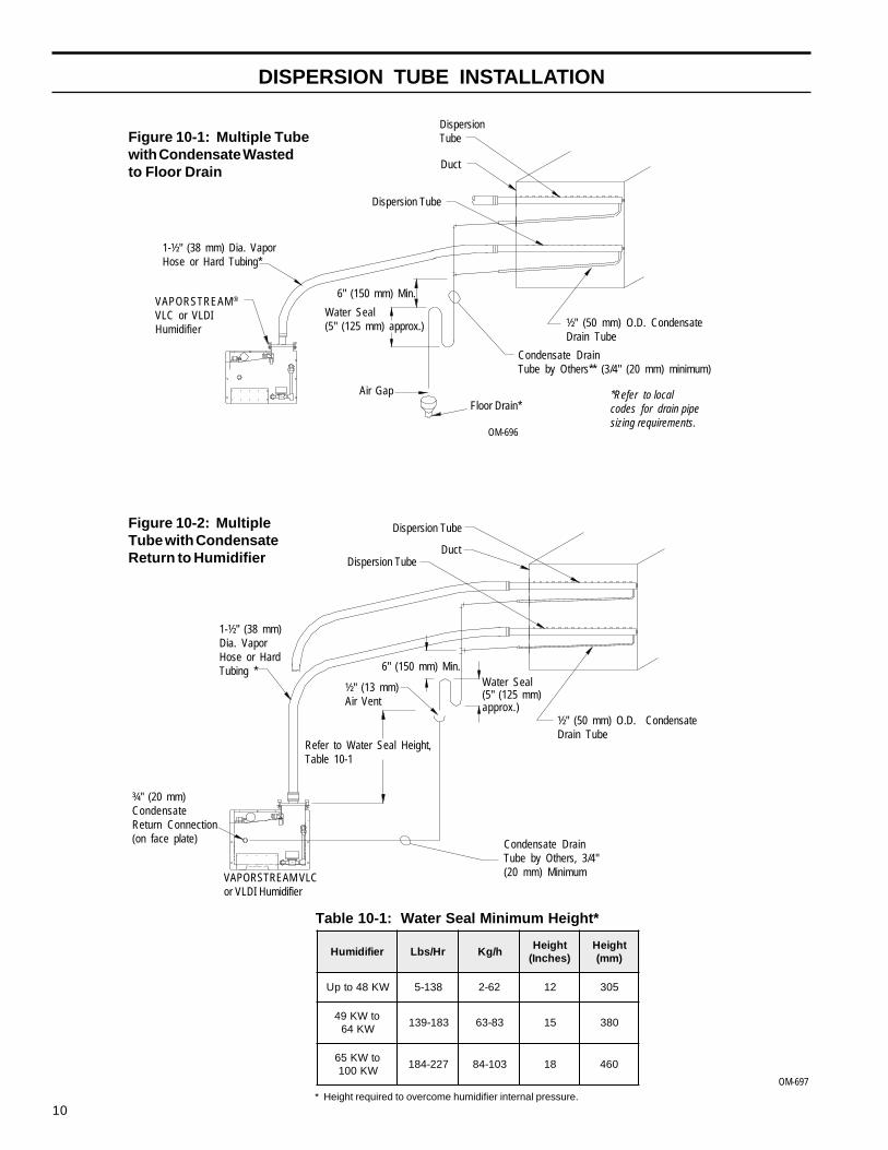
Table 10-1: Water Seal Minimum Height*
* Height required to overcome humidifier internal pressure.
Figure 10-1: Multiple Tubewith Condensate Wastedto Floor Drain
DispersionTube
Duct
Dispersion Tube
VAPORSTREAM®
VLC or VLDIHumidifier
1-½" (38 mm) Dia. VaporHose or Hard Tubing*
Water Seal(5" (125 mm) approx.)
6" (150 mm) Min.
Floor Drain*
Condensate DrainTube by Others** (3/4" (20 mm) minimum)
*Refer to localcodes for drain pipesizing requirements.
OM-696
½" (50 mm) O.D. CondensateDrain Tube
Figure 10-2: MultipleTube with CondensateReturn to Humidifier
Dispersion Tube
Dispersion TubeDuct
Water Seal(5" (125 mm)approx.)
½" (13 mm)Air Vent
6" (150 mm) Min.
1-½" (38 mm)Dia. VaporHose or HardTubing *
Condensate DrainTube by Others, 3/4"(20 mm) Minimum
Refer to Water Seal Height,Table 10-1
VAPORSTREAM VLCor VLDI Humidifier
¾" (20 mm)CondensateReturn Connection(on face plate)
½" (50 mm) O.D. CondensateDrain Tube
Air Gap
DISPERSION TUBE INSTALLATION
reifidimuH rH/sbL h/gKthgieH)sehcnI(
thgieH)mm(
WK84otpU 831-5 26-2 21 503
otWK94WK46
381-931 38-36 51 083
otWK56WK001
722-481 301-48 81 064
11
OPTIONAL WEATHER COVER
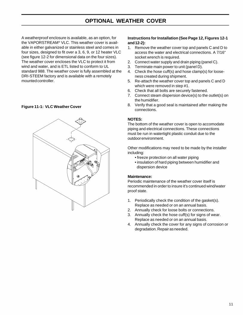
A weatherproof enclosure is available, as an option, forthe VAPORSTREAM® VLC. This weather cover is avail-able in either galvanized or stainless steel and comes infour sizes, designed to fit over a 3, 6, 9, or 12 heater VLC(see figure 12-2 for dimensional data on the four sizes).The weather cover encloses the VLC to protect it fromwind and water, and is ETL listed to conform to ULstandard 988. The weather cover is fully assembled at theDRI-STEEM factory and is available with a remotelymounted controller.
Instructions for Installation (See Page 12, Figures 12-1and 12-2):1. Remove the weather cover top and panels C and D to
access the water and electrical connections. A 7/16"socket wrench is required.
2. Connect water supply and drain piping (panel C).3. Terminate main power to unit (panel D).4. Check the hose cuff(s) and hose clamp(s) for loose-
ness created during shipment.5. Re-attach the weather cover top and panels C and D
which were removed in step #1.6. Check that all bolts are securely fastened.7. Connect steam dispersion device(s) to the outlet(s) on
the humidifier.8. Verify that a good seal is maintained after making the
connections.
NOTES:The bottom of the weather cover is open to accomodatepiping and electrical connections. These connectionsmust be run in watertight plastic conduit due to theoutdoor environment.
Other modifications may need to be made by the installerincluding:
• freeze protection on all water piping• insulation of hard piping between humidifier and dispersion device
Maintenance:Periodic maintenance of the weather cover itself isrecommended in order to insure it's continued wind/waterproof state.
1. Periodically check the condition of the gasket(s).Replace as needed or on an annual basis.
2. Annually check for loose bolts or connections.3. Annually check the hose cuff(s) for signs of wear.
Replace as needed or on an annual basis.4. Annually check the cover for any signs of corrosion or
degradation. Repair as needed.
Figure 11-1: VLC Weather Cover

12
WEATHER COVER DIMENSIONS
Figure 12-1: Weather Cover Exploded View
Table 12-1: 3, 6, 9, and 12 Heater Overall Dimensions of Weather Cover
Panel A
Top Panel
Panel D
Panel C
OM-906A
Panel B
Figure 12-2: Weather Cover Dimensions
OM-904
PanelIdentificationLabel
B ETL Certification Label
A
C
Product Identification Label
D
:2-21erugiFretteLtuollaC
noitpircseDtuollaCeerhT
sehcni(eerhT)mm(
xiSsehcni(
xiS)mm(
eniN)sehcni(
eniN)mm(
evlewT)sehcni(
evlewT)mm(
A thgieH ¾05 0921 ¾05 0921 ¾05 0921 ¾05 0921
B htgneL ½32 006 23 518 04 5101 ½74 5021
C htdiW 52 536 ½32 006 ½32 006 ½32 006
D mottobmorfecnatsiD ¾7 002 ¾7 002 ¾7 002 ¾7 002

13
RAPID-SORB® ASSEMBLY AND INSTALLATION
Instructions for Horizontal Duct1. Unpack shipment and verify receipt of allRAPID-SORB components with packing list. Reportany shortages to the DRI-STEEM factory immediately.
2. Provide necessary access in and around duct work.
3. Locate 1" x 1½" (25 mm x 38 mm) stainless steelchannel inside the duct. Hang the channel from the top ofthe duct, centered between duct side walls, with the twomounting holes provided.
4. If hose cuffs are used, slide cuffs over the open end ofeach tube. Install a pair of hose clamps on each tube.
5. Note direction of air flow within duct, then arrange eachdispersion tube so steam will discharge perpendicular tothe air flow. Use the hex bolts provided to attach tubes tooverhead 1" x 1½" (25 mm x 38 mm) channel. Do notsecure. If the header is outside the duct (see figure 13-2),punch-out necessary clearance holes in the base of theduct to slide dispersion tubes up from bottom.
6. For a Header Inside the Duct (See figure 13-1.):Punch or cut out necessary clearance holes forRAPID-SORB header. Slide header into the duct, positionheader and slide the dispersion tube hose cuffs or slipcouplings over the header dispersion tube nipples.
Position the header so vertical dispersion tubes areperpendicular to duct and pitch the header to condensatedrain. Secure header to the mounting bracket. Useescutcheon plates to secure header where it enters theduct.
Check that the dispersion tubes discharge steam perpen-dicular to the air flow. Secure tubes to the overheadchannel. Secure the channel to the duct. Position hosecuffs or slip couplings over tube and header tube nipples,and secure with clamps.
For a Header Outside the Duct (See figure 13-2.):Position header under dispersion tubes, then slide hosecuffs or slip couplings over header dispersion tube nipples.
Position the header so dispersion tubes are perpendicularto duct and pitch the header to condensate drain. Securedispersion tubes in place with the tube escutcheon platesprovided.
Check the position of the tubes for steam release perpen-dicular to the air flow. Secure tubes to the overheadchannel, and secure channel to the duct. With headerpitched to condensate drain, slip hose cuffs or slipcouplings over tube nipples and secure with clamps.
7. Connect a condensate drain to the header, provide thewater trap as shown, and run to open drain, sized accord-ing to local codes.
8. Attach the header steam supply connector to mainheader using the hose cuff and clamps provided, but donot secure.
9. Route the necessary number of vapor hoses or pipesfrom the humidifier tank, position connector to accept thehoses or pipes and secure.
Note: Refer to page 15 for vapor hose information onrouting and for alternate vapor hose installation methods.
Figure 13-1: RAPID-SORB UnitHeader Inside Duct
Top ofDuctor Casing
OM-102
CondensateDrain, 3/4" NPT
3/4" (20 mm)Copper
Air Gap
*Open Drain
Pitch 1/8"per foot(10 mm/m)minimum
Hose Cuffand Clamps
VAPORSTREAM® ModelVLC Humidifier
OrificedTubelets
A
A
DispersionTube
3/8-16 x ½"Hex HeadBolt
1" x 1-1/2" (25 mm x 38 mm)S.S.T.Channel (by DRI-STEEM)
Duct
EscutcheonPlate
Figure 13-2: RAPID-SORB UnitHeader Under Duct
Slip Couplingor Hose Cuff
View A-A
* Refer to local codes for drain pipe size requirements.OM-101
Dispersion Tube
OrificedTubelets
SlipCoupling orHose Cuff
Optional CompanionFlange or ThreadedConnection for Hard Piping
HeaderCondensateDrain,3/4" NPT
3/4" (20 mm)CopperAir Gap
*Open Drain
5"(125mm)Min.
6"(150mm)Min.
Nut andBolt
Duct orCasing
1" x 1-1/2" (25 mm x 38 mm)S.S.T. Channel (by DRI-STEEM)
Pitch 1/8" per foot (10 mm/m) minimum
MountingChannel
MountingNut
5"(125mm)Min.
6" (150mm) Min.
14
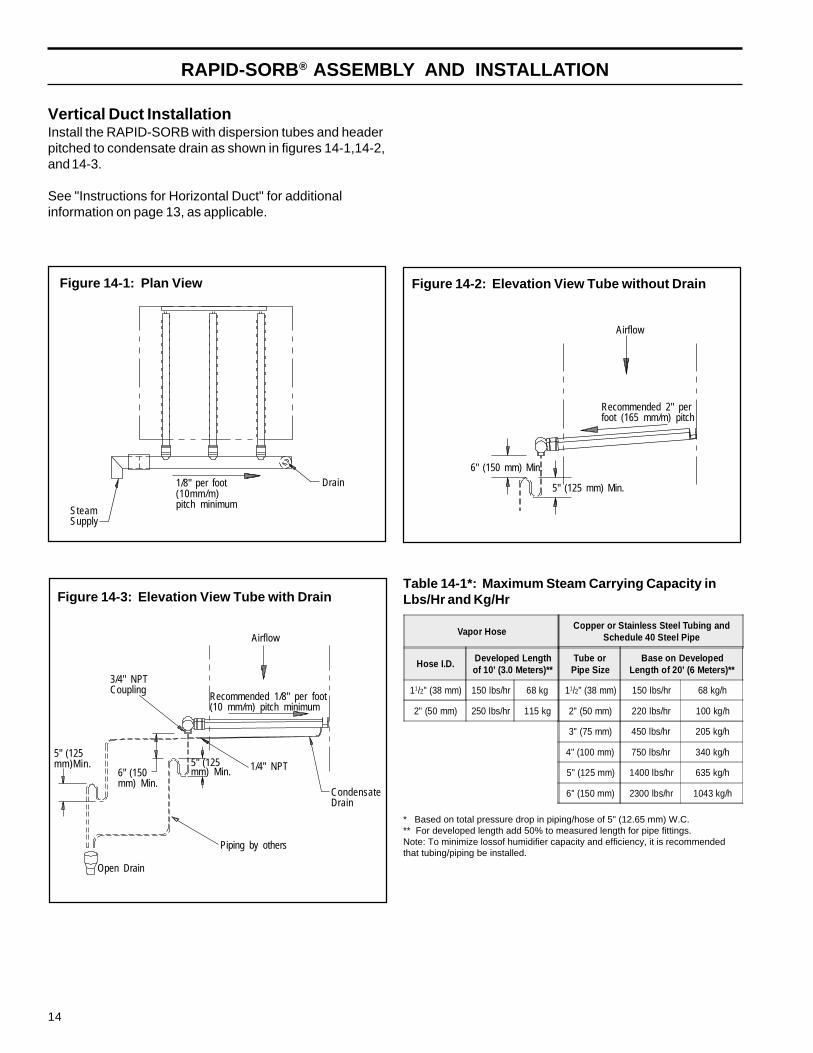
Figure 14-1: Plan View
SteamSupply
1/8" per foot(10mm/m)pitch minimum
Drain
RAPID-SORB® ASSEMBLY AND INSTALLATION
Vertical Duct InstallationInstall the RAPID-SORB with dispersion tubes and headerpitched to condensate drain as shown in figures 14-1,14-2,and 14-3.
See "Instructions for Horizontal Duct" for additionalinformation on page 13, as applicable.
Figure 14-2: Elevation View Tube without Drain
Figure 14-3: Elevation View Tube with DrainTable 14-1*: Maximum Steam Carrying Capacity inLbs/Hr and Kg/Hr
6" (150 mm) Min.
5" (125 mm) Min.
Recommended 2" perfoot (165 mm/m) pitch
Airflow
* Based on total pressure drop in piping/hose of 5" (12.65 mm) W.C.** For developed length add 50% to measured length for pipe fittings.Note: To minimize lossof humidifier capacity and efficiency, it is recommendedthat tubing/piping be installed.
1/4" NPT
Open Drain
3/4" NPTCoupling
CondensateDrain
Piping by others
Recommended 1/8" per foot(10 mm/m) pitch minimum
Airflow
5" (125mm)Min.
6" (150mm) Min.
5" (125mm) Min.
Vapor HoseCopper or Stainless Steel Tubing and
Schedule 40 Steel Pipe
Hose I.D. Developed Lengthof 10’ (3.0 Meters)**
Tube orPipe Size
Base on DevelopedLength of 20’ (6 Meters)**
11/2" (38 mm) 150 lbs/hr 68 kg 11/2" (38 mm) 150 lbs/hr 68 kg/h
2" (50 mm) 250 lbs/hr 115 kg 2" (50 mm) 220 lbs/hr 100 kg/h
3" (75 mm) 450 lbs/hr 205 kg/h
4" (100 mm) 750 lbs/hr 340 kg/h
5" (125 mm) 1400 lbs/hr 635 kg/h
6" (150 mm) 2300 lbs/hr 1043 kg/h
15
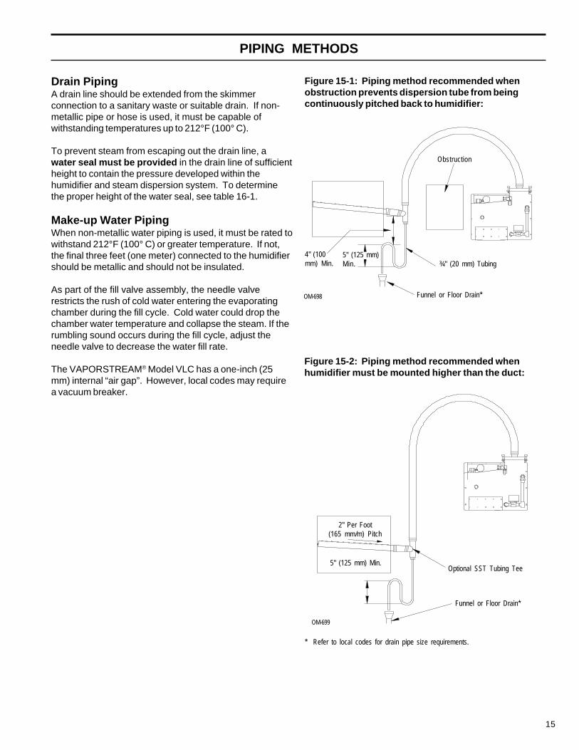
Figure 15-1: Piping method recommended whenobstruction prevents dispersion tube from beingcontinuously pitched back to humidifier:
Drain PipingA drain line should be extended from the skimmerconnection to a sanitary waste or suitable drain. If non-metallic pipe or hose is used, it must be capable ofwithstanding temperatures up to 212°F (100° C).
To prevent steam from escaping out the drain line, awater seal must be provided in the drain line of sufficientheight to contain the pressure developed within thehumidifier and steam dispersion system. To determinethe proper height of the water seal, see table 16-1.
Make-up Water PipingWhen non-metallic water piping is used, it must be rated towithstand 212°F (100° C) or greater temperature. If not,the final three feet (one meter) connected to the humidifiershould be metallic and should not be insulated.
As part of the fill valve assembly, the needle valverestricts the rush of cold water entering the evaporatingchamber during the fill cycle. Cold water could drop thechamber water temperature and collapse the steam. If therumbling sound occurs during the fill cycle, adjust theneedle valve to decrease the water fill rate.
The VAPORSTREAM® Model VLC has a one-inch (25mm) internal “air gap”. However, local codes may requirea vacuum breaker.
PIPING METHODS
Figure 15-2: Piping method recommended whenhumidifier must be mounted higher than the duct:
* Refer to local codes for drain pipe size requirements.
2" Per Foot(165 mm/m) Pitch
5" (125 mm) Min.
Funnel or Floor Drain*
OM-699
Optional SST Tubing Tee
OM-698 Funnel or Floor Drain*
Obstruction
¾" (20 mm) Tubing5" (125 mm)Min.
4" (100mm) Min.

16
PIPING DIAGRAMS: STEAM, WATER AND DRAIN
Alternate Water Seal and Drain Valve Piping (by installer)Used when water seal must be elevated above flow line of drain connection (humidifier near floor)
Standard Unit (Non-DI/RO Water)
Note: Drain piping material must be suitable for 212°F (100°C) water.
DI/RO Water Unit
Table 16-1: Water Seal Height (H)Recommendations
Note: If piping to dispersion tube is over 20 feet (6meters) increase water seal height by 15%.
OM-633
¾" (20 mm)SST Drain Valve
H
Float Operated WaterMake-up Valve
Overflow - ¾" (20 mm)
¼" (6 mm) NPT Water Supply,25 psi minimum, (172 kPa)
Drain and Water SealPiping - ¾" (20 mm)(by installer)
Air Gap
Open Drain *Float OperatedLow-Water Cut-off
Heaters
OM-634
Heaters H
Clean-out Tray
Clean-outPlate
Three Probe Level Controland Low-Water Cut-off Drain
ConnectionOpen Drain*
Air Gap
Drain and Water Seal Piping - ¾" (20 mm)(by installer)
Manual or Optional Electric Drain Valve
Water Supply Line (25 psi minimum)Water Skim/Overflow Outlet - ¾" (20 mm)
Needle Valve
Solenoid Water Make-up Valve
* Refer to local codes for drain pipe sizing and maximum temperature requirements.
OM-635
Solenoid WaterMake-up Valve
NeedleValve
Water Skim/Overflow Outlet
Water Supply Line,25 psi minimum,(172 kPa)
Note: FlowLine of WaterSeal cannotbe above FlowLine ofSkimmerOutlet
Air Gap
Open Drain*
Manual or Optional Electric Drain ValveDrain Connection
Clean-out Plate
reifidimuH rH/sbL h/gKthgieH)sehcnI(
thgieH)mm(
WK84otpU 831-5 26-2 21 503
otWK94WK46
381-931 38-36 51 083
otWK56WK001
722-481 301-48 81 064
Field installed forclean-out

17
START-UP PROCEDURE
IntroductionAfter the system has been properly installed and con-nected to both electrical and water supplies, it may thenbe started.
Start-up and Checkout ProceduresMountingCheck mounting to see that unit is level and securelysupported before filling with water.
PipingVerify that all piping connections have been completed asrecommended and that water pressure is available.
ElectricalVerify that all wiring connections have been made inaccordance with all governing codes and the enclosedVAPORSTREAM® VLC wiring diagram.
Caution: Only qualified electrical personnelshould perform start-up procedure.
Control SystemFor start-up instructions, see the operations and mainte-nance manual for your humidifier control system.
OPERATION
For operating instructions, see the VAPOR-LOGIC®
Installation Instructions and Maintenance OperationsManual.
Caution: Overtightening cover will cause leaks.All cover knobs are turned down at the factory until thebottom of the knob makes contact with the flange, thenone half turn further. If more compression is required,turn all knobs a half turn more. Do not turn knobs morethan a half turn before identifying that a leak still exists.

18
RECOMMENDED MAINTENANCE
VAPORSTREAM® Model VLC OnlyUsing softened water will significantly reduce mineralbuild-up in the humidifier. When softened water is notavailable, the VAPORSTREAM VLC is designed to dealwith water hardness in one of two ways depending on thedegree of hardness. For light to moderate hardness, up to10 grains per gallon ( 170 mg/l), using the surface waterskim time feature with annual cleaning is recommended.For high mineral content water, above 10 grains per gallon(170 mg/l), a periodic drain and flush through the motor-ized drain valve, in addition to the surface water skim timefeature, is recommended. The frequency of cleaning willdepend on water condition and evaporation load.
The humidifier should be inspected for leaks at leastannually. Also, the current draw of the heaters should bechecked and all safety devices in the control circuit shouldbe cycled on and off to verify that they are functioning.
Caution: When performing maintenance on theVAPORSTREAM Model VLC, always set control moduleswitch to "STBY” position, place main disconnect in “OFF”position, and close manual water shut-off valve.
Seasonally or as Required1. Cleaning Tank - Slide the clean-out tray out anddispose of any loose scale that has collected in the tray.This should be done before the build-up reaches theunderside of the heating elements.2. Cleaning Probes - Disconnect the plug and cableassembly and unscrew the probe holder from theVAPORSTREAM VLC unit. The scale will easily flake offfrom the sensing portion. The sensing portion, bottom3/8" (10 mm), of the probe should be brushed clean withstainless steel wool.3. Cleaning Skim Overflow Port - Loosen deposits witha long tool, such as a screwdriver. Proper skimmerdrainage should be verified by a weekly visual inspection.Water should drain from skimmer drain pipe after each fillcycle. (For cleaning piping, disconnect and flush out. Ifmineral deposits have restricted the flow, replace piping.)
Summer MaintenanceAfter the humidification season, a complete inspection andcleaning of the heaters, probe control, skimmer port, andwater chamber is recommended. After cleaning, the unitshould remain empty until humidification is required.
Adjusting the Surface Skim Bleed-Off QuantityThe skim time determines the quantity of water skimmedwith each fill cycle. The skim time is field adjustableusing the VAPOR-LOGIC® keypad.
Each time the VAPORSTREAM VLC refills, it fills to anelevation near the lip of the skim overflow fitting. Aportion of the refill water then flows to drain carrying theminerals floating on the water with it. This reduces themineral concentration, thereby reducing the frequency ofcleaning needed.
The heated water that flows to drain is a cost ofoperation. Cleaning the humidifier is also an operationalcost. Therefore, it is recommended that the user observeand adjust the skimming quantity. By doing so, a balancebetween minimizing mineral build-up and conserving hotwater can be achieved.
VAPORSTREAM Model VLDI OnlyThe humidifier should be inspected for leaks at leastannually. Also, the current draw of the heaters should bechecked and all safety devices in the control cabinetshould be cycled on and off to verify that they are func-tioning.
Make-up Water PipingUse cold or hot makeup water. If the water pressure isabove 60 psi (410 kPa) and/or water hammer would beobjectionable, a pressure reducing valve or shock arrestershould be installed. Even though the VAPORSTREAMVLC has an internal 1" (25 mm) air gap, some local codesmay require a vacuum breaker.
Caution: Minimum water supply pressure is 25 psi (172kPa).
Cleaning Evaporating ChamberAs long as mineral-free water is used in theVAPORSTREAM VLDI, no cleaning or flushing of theevaporating chamber should be necessary.
For trouble-shooting instructions, see the VAPOR-LOGIC®
Installation Instructions and Maintenance OperationsManual.
TROUBLE-SHOOTING GUIDE

19
REPLACEMENT PARTS
VAPORSTREAM® Model VLC Humidifier
TAB - Specify humidifier model and serialnumbers when ordering.
Notes:1. For dispersion tube(s) specify type
(L-tube, straight tube, RAPID-SORB®, etc)humidifier model and serial numbers.
2. Parts not itemized are typical hardwarestock items.
OM-907
No. Description Part No.
1 Tank 167700-TAB
2 Cover, One Heater 167710-TAB
2 Cover, Three Heater 167715-TAB
2 Cover, Six Heater 167720-TAB
2 Cover, Nine Heater 167725-TAB
2 Cover, Twelve Heater 167730-TAB
3 Cover, Heater Louvered 167740-TAB
4 Knob, T-Handled Utility 700725
5 Heater 409600-TAB
6 Gasket, Cover 160691-TAB
7 Clean-Out Plate 165472
8 Gasket, Clean-Out Plate 308225
9 Switch Door Interlock 408475
10 Thermal Cut-Out 409560-001
11 Valve, ¾" Ball (Manual Drain) 505011
12 Valve, ¾" Electric (Auto Drain) 505400-001
13 Probe Plug 406050-004
14 Probe Housing 308500
15 Probe Assembly 406015
16 Gasket, Probe 309750-004
17 Strainer, ¼" Sediment 300050
18 Valve, ¼" Needle 505070-001
19 Fill Valve, ¼" Solenoid 505084
20 Clean-Out Tray 167770-TAB
20
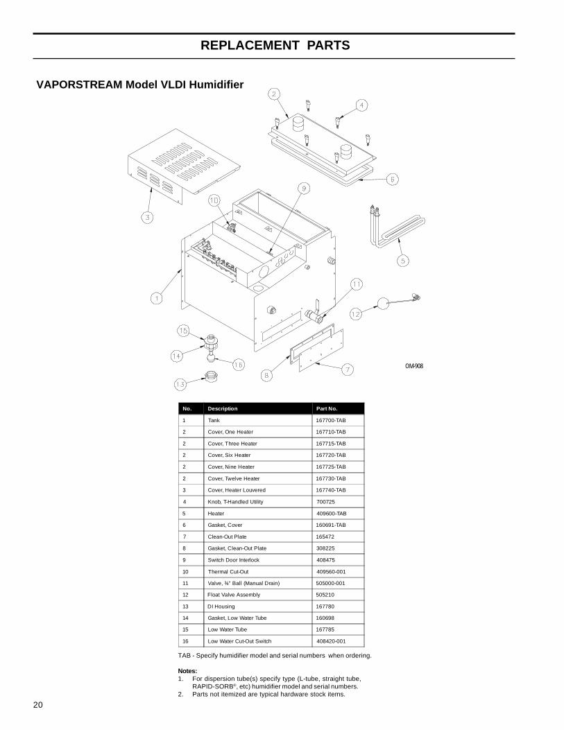
VAPORSTREAM Model VLDI Humidifier
OM-908
No. Description Part No.
1 Tank 167700-TAB
2 Cover, One Heater 167710-TAB
2 Cover, Three Heater 167715-TAB
2 Cover, Six Heater 167720-TAB
2 Cover, Nine Heater 167725-TAB
2 Cover, Twelve Heater 167730-TAB
3 Cover, Heater Louvered 167740-TAB
4 Knob, T-Handled Utility 700725
5 Heater 409600-TAB
6 Gasket, Cover 160691-TAB
7 Clean-Out Plate 165472
8 Gasket, Clean-Out Plate 308225
9 Switch Door Interlock 408475
10 Thermal Cut-Out 409560-001
11 Valve, ¾" Ball (Manual Drain) 505000-001
12 Float Valve Assembly 505210
13 DI Housing 167780
14 Gasket, Low Water Tube 160698
15 Low Water Tube 167785
16 Low Water Cut-Out Switch 408420-001
TAB - Specify humidifier model and serial numbers when ordering.
Notes:1. For dispersion tube(s) specify type (L-tube, straight tube,
RAPID-SORB®, etc) humidifier model and serial numbers.2. Parts not itemized are typical hardware stock items.
REPLACEMENT PARTS

21
DATEINSPECTED PERSONNEL OBSERVATION ACTION PERFORMED
MAINTENANCE SERVICE RECORD
22
DATEINSPECTED PERSONNEL OBSERVATION ACTION PERFORMED
MAINTENANCE SERVICE RECORD

23
TWO-YEAR LIMITED WARRANTY
DRI-STEEM Humidifier Company (“DRI-STEEM”) warrants to the original user that its products will be freefrom defects in materials and workmanship for a period of two (2) years after installation or twenty-seven (27)months from the date DRI-STEEM ships such product, whichever date is the earlier.
If any DRI-STEEM product is found to be defective in material or workmanship during the applicablewarranty period, DRI-STEEM’s entire liability, and the purchaser’s sole and exclusive remedy, shall bethe repair or replacement of the defective product, or the refund of the purchase price, at DRI-STEEM’selection. DRI-STEEM shall not be liable for any costs or expenses, whether direct or indirect, associated withthe installation, removal or re-installation of any defective product.
DRI-STEEM’s limited warranty shall not be effective or actionable unless there is compliance with all installa-tion and operating instructions furnished by DRI-STEEM, or if the products have been modified or alteredwithout the written consent of DRI-STEEM, or if such products have been subject to accident, misuse,mishandling, tampering, negligence or improper maintenance. Any warranty claim must be submitted toDRI-STEEM in writing within the stated warranty period.
DRI-STEEM’s limited warranty is made in lieu of, and DRI-STEEM disclaims all other warranties, whetherexpress or implied, including but not limited to any IMPLIED WARRANTY OF MERCHANTABILITY, ANYIMPLIED WARRANTY OF FITNESS FOR A PARTICULAR PURPOSE, any implied warranty arising out of acourse of dealing or of performance, custom or usage of trade.
DRI-STEEM SHALL NOT, UNDER ANY CIRCUMSTANCES BE LIABLE FOR ANY DIRECT, INDIRECT,INCIDENTAL, SPECIAL OR CONSEQUENTIAL DAMAGES (INCLUDING, BUT NOT LIMITED TO, LOSS OFPROFITS, REVENUE OR BUSINESS) OR DAMAGE OR INJURY TO PERSONS OR PROPERTY IN ANYWAY RELATED TO THE MANUFACTURE OR THE USE OF ITS PRODUCTS. The exclusion appliesregardless of whether such damages are sought based on breach of warranty, breach of contract,negligence, strict liability in tort, or any other legal theory, even if DRI-STEEM has notice of the possibilityof such damages.
By purchasing DRI-STEEM’s products, the purchaser agrees to the terms and conditions of this limitedwarranty.

Form No. VLCOM-0300 Copyright © 2000 DRI-STEEM Humidifier Company Printed in U.S.A.
Continuous product improvement is a policy of DRI-STEEM Humidifier Company therefore, product features and specifications are subject to change without notice.
DRI-STEEM, RAPID-SORB, STS, LTS, VAPOR-LOGIC and VAPOR-LOGIC2 are Registered Trademarks of the DRI-STEEM Humidifier Company.TEFLON is a Registered Trademark of Dupont.
14949 Technology Drive • Eden Prairie, MN 55344Phone: (952) 949-2415 • 800-328-4447 • Fax: (952) 949-2933E-Mail: [email protected] • Web: www.dristeem.comEurope Office:Bell Place, Bell Lane • Syresham, Brackley • NN13 5HP, U.K.Phone: +44 1280 850122 • Fax: +44 1280 850124E-Mail: [email protected]