Embed Size (px)
Citation preview

VAPOR RECOVERY SYSTEMS
Technical Description ~ Dry Vacuum Systems SYMEX Americas, LLC
5397 West 86th Street or P.O. Box 681246 Indianapolis, IN 46268
Phone: 317-872-4321 Attention: Tim Hammond, Pres.
or SYMEX Americas, LLC 6840 East 112th Street South
Bixby, OK 74008-2062 Phone 918-231-9698
Attention: Bill Ball, VP E-Mail: [email protected]
SYMEX AMERICAS 01 / Docs / VRU / 1131 / TD SN D 00-10-05E
SYMEX Americas: Technical Description August 2003 DryVAC™ Vapor Recovery System Page 2
Index 1 PROCESS.......................................................................................................................................................4
1.1 INTRODUCTION..............................................................................................................................................4 1.2 BRIEF DESCRIPTION OF THE PROCESS.........................................................................................................4 1.3 THE PRINCIPAL OF ADSORPTION.................................................................................................................6 1.4 MECHANICAL DESORPTION PROCESS .........................................................................................................6
2 PROCESS MONITORING AND CONTROL ...........................................................................................8
2.1 INTRODUCTION..............................................................................................................................................8 2.2 SAFE AREA CONTROLS CABIN.....................................................................................................................8 2.3 OPERATION ....................................................................................................................................................9
2.3.1 OFF Position...................................................................................................................................................9 2.3.2 ON Position .....................................................................................................................................................9 2.3.3 PC Position....................................................................................................................................................11
3 SAFETY .......................................................................................................................................................11
3.1 INTRODUCTION............................................................................................................................................11 3.2 HAZARDS......................................................................................................................................................11 3.3 PREVENTIVE MEASURES ............................................................................................................................12
3.3.1 Construction ..................................................................................................................................................12 3.3.2 Design............................................................................................................................................................12 3.3.3 Electrical Components ..................................................................................................................................13 3.3.4 Checks and Maintenance...............................................................................................................................13
3.4 SAFE GUARDING SYSTEM ..........................................................................................................................14 3.5 SITE REQUIREMENTS ..................................................................................................................................15 3.6 SAFETY ZONE CLASSIFICATION ................................................................................................................15
3.6.1 Vapor inlet.....................................................................................................................................................15 3.6.2 Vapor Outlet ..................................................................................................................................................15 3.6.3 Vacuum System..............................................................................................................................................16 3.6.4 Absorber and return line ...............................................................................................................................16 3.6.5 Surroundings of the regeneration system ......................................................................................................16 3.6.6 Surroundings of the adsorber vessels............................................................................................................17 3.6.7 Vent opening or stack ....................................................................................................................................17
4 SPECIFICATIONS .....................................................................................................................................17
4.1 CODES & STANDARDS ................................................................................................................................17
4.1.1 Emission ........................................................................................................................................................18 4.1.2 Health & Safety .............................................................................................................................................19 4.1.3 Construction ..................................................................................................................................................19
4.2 CONSTRUCTIVE DETAILS ...........................................................................................................................21
4.2.1 Adsorber Vessels ...........................................................................................................................................21 4.2.2 Absorber Vessel .............................................................................................................................................22 4.2.3 Vacuum Pump ...............................................................................................................................................22 4.2.4 Absorbents Circulation Pumps......................................................................................................................23 4.2.5 Sequential Valves ..........................................................................................................................................23
© 2003 SYMEX Americas. All Rights Reserved.
This document is proprietary to SYMEX Americas, LLC and shall not be reproduced without prior written authorisation.

SYMEX Americas: Technical Description August 2003 DryVAC™ Vapor Recovery System Page 3
4.3 INSTRUMENTATION.....................................................................................................................................24
4.3.1 Pressure.........................................................................................................................................................24 4.3.2 Temperature ..................................................................................................................................................25 4.3.3 Level ..............................................................................................................................................................25 4.3.4 Flow...............................................................................................................................................................26 4.3.5. Hydrocarbon emission transmitter................................................................................................................26
© 2003 SYMEX Americas. All Rights Reserved.
This document is proprietary to SYMEX Americas, LLC and shall not be reproduced without prior written authorisation.

SYMEX Americas: Technical Description August 2003 DryVAC™ Vapor Recovery System Page 4
1 PROCESS
1.1 Introduction
Legislation is being prepared world wide or is already in place to limit gaseous hydrocarbon emissions to atmosphere. A large portion of these emissions are formed by volatile hydrocarbon compounds derived from the manufacturing, transportation, and application of most liquid petroleum products. It is a well known fact that hydrocarbon vapors emitted to the atmosphere, and in the presence of ultra violet light from the sun, for low-level atmospheric Ozone. Low level Ozone has been identified as a major precursor to the formation of SMOG. These and other hydrocarbon components such as Benzene, Toluene, and Xylene, are now known to be carcinogenic (cancer causing to humans). In an effort to minimize air pollution and the incidence of cancer, many organizations around the world have established guidelines for maximum emission levels of various hydrocarbon and chemical components. These are known globally as the United States EPA, the German TA-Luft, and the EC Directive for Petroleum Terminals and many similar national regulations. The European Union plans to reduce the problem of hydrocarbon emissions in a period of ten years. Mexico and Chile have similar plans. And, other countries are in the process of implementing the necessary environmental improvement legislation and enforcement laws to do so in the near future. To help reduce air pollution from the manufacture and handling of chemical- and petrochemical products SYMEX Americas Vapor Recovery System was developed. It recovers and eliminates emissions, using as little energy as possible and without creating secondary waste products. We call it “DryVAC™: The DryVAC™ system can reduce the concentration of volatile compounds. These include hydrocarbons such as:
alkanes (Ethane, Propane, Butane, etc.), cyclic hydrocarbons (Benzene, Toluene, Xylene, and Cyclo-hexane) and solvents (Methanol, Acetone, etc.) in a carrier gas (e.g. air, Nitrogen)
These and many other compounds can be effectively removed from emissions streams and recovered in their pure form, or in like or similar absorbents. Any purified carrier gas, such as air, can either be vented to atmosphere or stored and recycled.
1.2 Brief description of the process
Storage tanks, ships, railcars or truck tankers maintain a vapor space above the liquid level with a relatively high concentration of volatile vapor components. During the filling of these vessels, these vapor phase components are displaced to atmosphere by the liquid. This volatile organic
© 2003 SYMEX Americas. All Rights Reserved.
This document is proprietary to SYMEX Americas, LLC and shall not be reproduced without prior written authorisation.

SYMEX Americas: Technical Description August 2003 DryVAC™ Vapor Recovery System Page 5
vapor mixture can be entirely removed before it escapes to atmosphere by the SYMEX Americas Vapor Recovery System, thus preventing pollution while recovering the valuable products.
Our vapor recovery process consists of two adsorber vessels for continuous operation, containing adsorbents (activated carbon) which collect the offensive compounds from the vapor stream flowing to atmosphere. The offensive vapor mixture flows upwards through one of two activated carbon beds. The components to be removed are adsorbed onto the surface of a special activated carbon, while the purified air or inert gas is vented from the top of the adsorber to the atmosphere. Each carbon bed is sized to adsorb a given quantity of hydrocarbon vapor. After a predetermined time, and before the in-service bed is completely saturated, the gas flow is switched to the other bed. The nearly saturated bed is then regenerated by means of a deep vacuum. The regeneration vacuum is generated by means of one or more dry screw vacuum pumps (thus the name DryVAC™). Since the regenerating carbon bed is closed in during regeneration, the hydrocarbons being desorbed from the activated carbon by the negative pressure of the vacuum leave the carbon vessel at high concentration. These concentrated vapors are compressed
through an absorption column where they are absorbed by virtue of counter-current flow over a large surface area medium into a liquid absorbent. The absorbent used is one of the products handled at the loading facility.
© 2003 SYMEX Americas. All Rights Reserved.
This document is proprietary to SYMEX Americas, LLC and shall not be reproduced without prior written authorisation.
SYMEX Americas: Technical Description August 2003 DryVAC™ Vapor Recovery System Page 6
1.3 The Principal of Adsorption
Many solids have an affinity towards liquids or gases. This affinity is called adhesion. The phenomenon is caused by imbalance of forces at the surface of the solid where, in a crystalline structure, the continuity of the interactive forces between the atoms is interrupted, looking for compensation from the outside. This compensation can be given by the molecules in a gas surrounding the surface of the solid carbon particle. The gas molecules loose part of their kinetic energy and become more or less attached to the surface of the solid carbon particle as a thin layer. It appears that some components in the gas mixture are more attracted then others, resulting in a selective removal of these components from the gas mixture. Larger hydrocarbon molecules seem to be more attracted to the surface of activated carbon than small ones, while water vapor is much less affected and air is hardly affected at all.
It is apparent that the adsorption capacity of the adsorbent is directly proportional to the total free surface per unit of weight of the adsorbent. The special activated carbon used by SYMEX Americas has a vast internal pore structure. It is estimated to have a free internal surface of at least nine million square feet per pound; enormous by any standards. This carbon provides a loading factor of more than 100 % by weight for the vapor phase components normally at issue. Adsorbents are considered completely saturated when their free surface is completely utilized.
The carbon loading factor (pounds of product adsorbed per pound of adsorbents) is positively influenced by:
increase of pressure, decrease of temperature of the process, a higher concentration of the components to be adsorbed.
1.4 Mechanical desorption process
Desorption is the opposite of adsorption. By reversing the conditions which influence the ability of an adsorbent to adsorb, the adsorption process will be reversed. This is desorption. Desorption causes the adsorbed components to be freed and form a higher concentration than was present in the original gas mixture. The three predominant ways to accomplish desorption are:
increasing the temperature (thermal regeneration), decreasing the pressure (pressure swing desorption, often using a vacuum), lowering the concentration of the components in the adsorbents (purging).
Any of the above will reverse the adsorption process, causing desorption to occur. A combination of these desorption techniques can serve to improve desorption even further. In any event, when the desorbed concentrated vapor mixture is removed from the adsorber vessel, it can then be recovered. Typical recovery processes are compression and cooling, absorption into a liquid, condensation, etc. The recovery method selected is usually chosen by applying normal
© 2003 SYMEX Americas. All Rights Reserved.
This document is proprietary to SYMEX Americas, LLC and shall not be reproduced without prior written authorisation.

SYMEX Americas: Technical Description August 2003 DryVAC™ Vapor Recovery System Page 7
business parameters such as cost, availability, simplicity, operating costs, maintenance costs, and replacement frequency. The mechanical desorption process employed in DryVAC™ uses a vacuum system to lower the pressure in the adsorber vessels. This negative pressure breaks the bond between the carbon and the vapor. The result is to liberate the adsorbed vapor components. In order to achieve the very low emission levels normally requires today, purging is also required during the desorption process. The desorbed vapor components are then compressed by the vacuum system to above atmospheric pressure and flow upwards through an absorber column where they come into intimate counter flowing contact with the liquid absorbent, are cooled and liquefied. This is the process of vapor recovery. A fraction of the desorbed components together with a part of the carrier gas and purge gas is recycled via an adsorber on line back into the on-line adsorber column, so no hydrocarbons are emitted to atmosphere.
The vacuum system consists of one, or a series of dry screw vacuum compressors. These special vacuum compressors are able to handle the slugs of liquid eventually formed inside the pump by virtue of natural compression-condensation as the concentration of hydrocarbons increases in the vapor coming from the adsorber vessels.
The exhaust temperature of the dry screw vacuum compressor is very low (around 104°F), and generally does not exceeds 140°F.
The compressor speed is controlled by means of a variable frequency controller. The speed is
adjusted as a function of the required vacuum level. This way the power consumption is directly linked to the amount
of hydrocarbon vapors desorbed. The recovery section down stream the vacuum system can be either directly or indirectly cooled. The recovered product is collected in a sump and pumped back to storage. The absorption or condensation temperature is chosen at a level to insure the recycle flow to be in the range of 10 to 25 %. The SYMEX Americas dry vacuum adsorption process, SN/D is simple and requires little maintenance. Energy consumption is very low compared to wet vacuum systems and requires only 0.0028 to 0.0043 kWh per ft3 of vapor mixture treated, based on the daily throughput. The absorbent used in the absorber column is usually one of the products stored or handled at the terminal (gasoline, platformate, naptha, crude oil, benzene, methanol, etc.).
© 2003 SYMEX Americas. All Rights Reserved.
This document is proprietary to SYMEX Americas, LLC and shall not be reproduced without prior written authorisation.
SYMEX Americas: Technical Description August 2003 DryVAC™ Vapor Recovery System Page 8
2 PROCESS MONITORING AND CONTROL
2.1 Introduction
In general the controls system consists of : • Locally mounted instruments, suitable for the zone qualification in which the system is
operating (in most cases Class 1, Division 2) • A Programmable Logical Controller PLC • A Human Machine Interface HMI • A PC based supervision system to be installed in the Control Room
SYMEX Americas uses the Siemens PLC series S7 for process control purposes as a standard. This PLC is linked through an interface with a PC based supervision system with modem connection to the SYMEX Americas headquarters in Indianapolis, Indiana, USA. For supervision purposes SYMEX Americas has developed a Process Supervising System based on PC-View, with alarm display and histograms. Visualisation of the VRS can be also integrated in a terminal automation system, supplied by SYMEX Americas or others. The DryVAC™ Vapor Recovery System (VRS) is fully automated and suitable for unmanned operations. All of the remote operated valves are normally electrical motor operated. All important remote operated valve positions, process temperatures and running signals of the pumps are continuously monitored. To cover the different field circumstances and customer requirements a number of alternative arrangements can be offered.
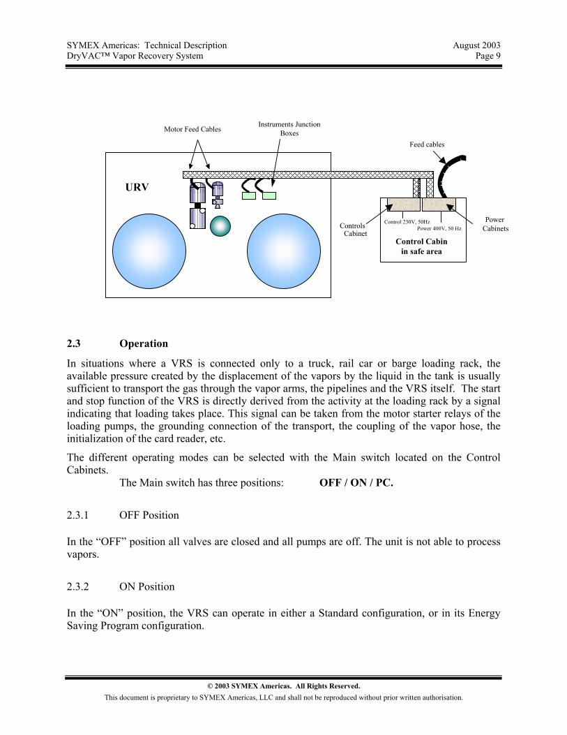
2.2 Safe Area Controls Cabin
In order to provide safe and easy access to the electrical components under all weather conditions, the PLC, the auxiliary components and the motor starter relays are mounted in safe area cabinets in an unclassified area in an existing safe area control room or in a remote control cabin installed at a distance of 50’ to 150’ from the VRS. This control cabin can be supplied by SYMEX Americas with heating and/or air-conditioning equipment and lighting fixtures.
© 2003 SYMEX Americas. All Rights Reserved.
This document is proprietary to SYMEX Americas, LLC and shall not be reproduced without prior written authorisation.
SYMEX Americas: Technical Description August 2003 DryVAC™ Vapor Recovery System Page 9
Motor Feed Cables
Feed cables
ControlsCabinet
PowerCabinets
Control Cabinin safe area
URV
Instruments JunctionBoxes
Control 230V, 50HzPower 400V, 50 Hz
2.3 Operation
In situations where a VRS is connected only to a truck, rail car or barge loading rack, the available pressure created by the displacement of the vapors by the liquid in the tank is usually sufficient to transport the gas through the vapor arms, the pipelines and the VRS itself. The start and stop function of the VRS is directly derived from the activity at the loading rack by a signal indicating that loading takes place. This signal can be taken from the motor starter relays of the loading pumps, the grounding connection of the transport, the coupling of the vapor hose, the initialization of the card reader, etc.
The different operating modes can be selected with the Main switch located on the Control Cabinets.
The Main switch has three positions: OFF / ON / PC.
2.3.1 OFF Position
In the “OFF” position all valves are closed and all pumps are off. The unit is not able to process vapors.
2.3.2 ON Position
In the “ON” position, the VRS can operate in either a Standard configuration, or in its Energy Saving Program configuration.
© 2003 SYMEX Americas. All Rights Reserved.
This document is proprietary to SYMEX Americas, LLC and shall not be reproduced without prior written authorisation.
SYMEX Americas: Technical Description August 2003 DryVAC™ Vapor Recovery System Page 10
Standard Configuration
In the Standard (Normal) Configuration, the VRS runs independent of whether there is loading or not. All valves and pumps operate according to, and are safeguarded by, the PLC program. The VRS switches from one adsorber to the other every cycle until the VRS is switched to the “OFF” position. Energy Saving Program Configuration
In normal operating conditions, the DryVAC™ VRS runs in the Energy Saving Program
configuration. This mode takes into consideration both the activity of the loading rack and controls the capacity of adsorption of the activated carbons.
This energy saving program is included in the DryVAC™ VRS Package.
The system is based on the fact that the final desorption pressure varies with the load of hydrocarbons on the activated carbon. The desorption pressure is constantly monitored by a
pressure transmitter. As soon as a predestined vacuum level is reached, the speed of the vacuum compressor is decreased by means of a frequency controller. If sufficient buffer is determined
on the carbon bed, the PLC program will prolong the start of a new cycle until a certain volume of vapor has passed through the bed. This volume can be estimated or taken from the loading
automation system. Eventual variations in vapor concentration due to diesel, jet fuel, heating oil or other low-RVP product loading, will also be equalized by the PLC.
By combining dry screw vacuum pumps with variable frequency controllers, the energy consumption becomes proportional to the mass of hydrocarbons to be recovered.
The controlled desorption final pressure monitoring system also prevents the beds from being regenerated too deeply
and increases the safety of the system against bed overheating problems.
Special Sequences Special Sequences (Normal, Preloading, Evacuation, Absorbents Filling, Absorbents Emptying, and Absorbents Circulation) can also be selected from the HMI or from the PC for maintenance operations.
© 2003 SYMEX Americas. All Rights Reserved.
This document is proprietary to SYMEX Americas, LLC and shall not be reproduced without prior written authorisation.

SYMEX Americas: Technical Description August 2003 DryVAC™ Vapor Recovery System Page 11
The compressor, pumps, and valves can also be operated manually for maintenance purposes by means of the HMI, or from the PC.
2.3.3 PC Position
When the PC operating position is selected, the selection of any mode or functions on the PC installed in the main control room will prevail over the HMI. This gives the owner the possibility of operating the VRU directly from a supervisory position.
3 SAFETY
3.1 Introduction
Although Hydrocarbon Vapor Recovery Systems utilising activated carbon and vacuum regeneration are considered to be very safe, they are by definition used in situations where potential hazards exist; hazards like fire, explosion, and toxic emissions. A VRS must therefore be designed in such a way that the risk of dangerous situations and effects of failures on operating personnel, other systems, facilities in the direct surroundings of the VRS, and the general environment, are kept to a minimum. What follows is intended to provide the end user of a DryVAC™ VRS with basic information concerning the safety measures incorporated in the unit as standard, as well as requirements and measures to be emphasised on location.
3.2 Hazards
Possible hazards that occur during operation of a Vapor Recovery System are:
• Internal and external fire and explosion with generation of toxic combustion products, heat radiation and shock waves.
• Emission of toxic vapors, caused by malfunctioning or leakage of the VRS. • Leakage of liquids causing pollution of surface water and soil.
Other dangers like those coming from rotating equipment, working at high elevations, insufficient head room and space for servicing and maintenance, all have to be recognised and minimised.
© 2003 SYMEX Americas. All Rights Reserved.
This document is proprietary to SYMEX Americas, LLC and shall not be reproduced without prior written authorisation.
SYMEX Americas: Technical Description August 2003 DryVAC™ Vapor Recovery System Page 12
3.3 Preventive Measures
3.3.1 Construction
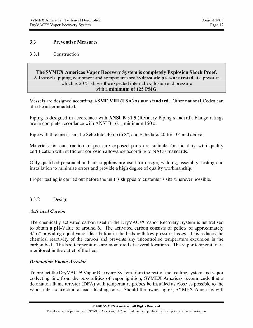
The SYMEX Americas Vapor Recovery System is completely Explosion Shock Proof.
All vessels, piping, equipment and components are hydrostatic pressure tested at a pressure which is 20 % above the expected internal explosion end pressure
with a minimum of 125 PSIG. Vessels are designed according ASME VIII (USA) as our standard. Other national Codes can also be accommodated. Piping is designed in accordance with ANSI B 31.5 (Refinery Piping standard). Flange ratings are in complete accordance with ANSI B 16.1, minimum 150 #. Pipe wall thickness shall be Schedule. 40 up to 8", and Schedule. 20 for 10" and above. Materials for construction of pressure exposed parts are suitable for the duty with quality certification with sufficient corrosion allowance according to NACE Standards. Only qualified personnel and sub-suppliers are used for design, welding, assembly, testing and installation to minimise errors and provide a high degree of quality workmanship. Proper testing is carried out before the unit is shipped to customer’s site wherever possible.
3.3.2 Design
Activated Carbon The chemically activated carbon used in the DryVAC™ Vapor Recovery System is neutralised to obtain a pH-Value of around 6. The activated carbon consists of pellets of approximately 3/16” providing equal vapor distribution in the beds with low pressure losses. This reduces the chemical reactivity of the carbon and prevents any uncontrolled temperature excursion in the carbon bed. The bed temperatures are monitored at several locations. The vapor temperature is monitored in the outlet of the bed. Detonation-Flame Arrestor To protect the DryVAC™ Vapor Recovery System from the rest of the loading system and vapor collecting line from the possibilities of vapor ignition, SYMEX Americas recommends that a detonation flame arrestor (DFA) with temperature probes be installed as close as possible to the vapor inlet connection at each loading rack. Should the owner agree, SYMEX Americas will
© 2003 SYMEX Americas. All Rights Reserved.
This document is proprietary to SYMEX Americas, LLC and shall not be reproduced without prior written authorisation.
SYMEX Americas: Technical Description August 2003 DryVAC™ Vapor Recovery System Page 13
conduct the necessary pressure drop study, and supply the appropriate DFA types and sizes to allow loading at the lowest practical pressure drop. Dry Screw type Vacuum Pump A special dry screw vacuum compressor is used to desorb volatile vapors from the adsorbers and move them into an absorber. There is no metallic contact between the moving parts inside the pump, thus eliminating the possibility of sparking and ignition. The dry screws on the vacuum compressor are Teflon-coated (not lined) as an additional measure against sparking. The pump casing is externally cooled to keep the casing well below the ignition temperature of the vapors. The temperature of the discharge of the vacuum pump is constantly monitored by the PLC as a safety safeguard. Any change in power consumption or shaft load is detected by a variable frequency controller, which stops the process when an unusual operating condition is detected. The compressor dry screws have a continuously varying pitch resulting in a very low energy consumption and compression end temperature. Liquid level The circulation pumps for absorbents are located below their respective liquid levels to prevent them from cavitating or running dry. The liquid levels controlled by level transmitters signalling variable frequency controllers, and are monitored continuously. The internal temperature of canned motor pumps is also monitored constantly in real time.
Valves positions All important valve positions and pump running signals are monitored by the PLC.
3.3.3 Electrical Components
Electrical components are selected to suit the hazardous area classification in which the are used. They are safe in a Class 1, Division 2 area.
3.3.4 Checks and Maintenance
The SYMEX Americas Vapor Recovery System is designed to operate fully automatically and unmanned. However, the risk of component failure can be minimised if the unit is checked daily for any unusual noises, vibrations, off-spec temperatures and/or liquid levels. A daily 15 minute effort is recommended to determine the actual status of the unit. SYMEX Americas provides a Preventive Maintenance Checklist with the unit to indicate points of attention as well as the recommended schedule of operator check work. An annual vibration test with frequency analyses is recommended for all rotating equipment.
© 2003 SYMEX Americas. All Rights Reserved.
This document is proprietary to SYMEX Americas, LLC and shall not be reproduced without prior written authorisation.
SYMEX Americas: Technical Description August 2003 DryVAC™ Vapor Recovery System Page 14
3.4 Safeguarding System
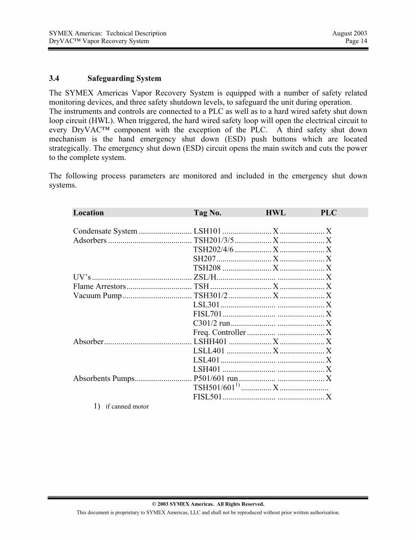
The SYMEX Americas Vapor Recovery System is equipped with a number of safety related monitoring devices, and three safety shutdown levels, to safeguard the unit during operation. The instruments and controls are connected to a PLC as well as to a hard wired safety shut down loop circuit (HWL). When triggered, the hard wired safety loop will open the electrical circuit to every DryVAC™ component with the exception of the PLC. A third safety shut down mechanism is the hand emergency shut down (ESD) push buttons which are located strategically. The emergency shut down (ESD) circuit opens the main switch and cuts the power to the complete system. The following process parameters are monitored and included in the emergency shut down systems.
Location Tag No. HWL PLC Condensate System .......................... LSH101 ........................ X ...................... X Adsorbers ......................................... TSH201/3/5.................. X ...................... X
TSH202/4/6 .................. X ...................... X SH207........................... X ...................... X TSH208 ........................ X ...................... X
UV’s ................................................. ZSL/H............................. ....................... X Flame Arrestors................................ TSH .............................. X ...................... X Vacuum Pump.................................. TSH301/2 ..................... X ...................... X
LSL301........................... ....................... X FISL701.......................... ....................... X C301/2 run...................... ....................... X Freq. Controller .............. ....................... X
Absorber........................................... LSHH401 ..................... X ...................... X LSLL401 ...................... X ...................... X LSL401........................... ....................... X LSH401 .......................... ....................... X
Absorbents Pumps............................ P501/601 run .................. ....................... X TSH501/6011) ............... X ........................ FISL501.......................... ....................... X
1) if canned motor
© 2003 SYMEX Americas. All Rights Reserved.
This document is proprietary to SYMEX Americas, LLC and shall not be reproduced without prior written authorisation.
SYMEX Americas: Technical Description August 2003 DryVAC™ Vapor Recovery System Page 15
3.5 Site Requirements
The end user is responsible to locate the VRS a sufficient distance from all public roads, railways etc., and to ensure that escape routes are foreseen and kept free. The VRS must be installed on a rigid concrete foundation. A containment curb is highly recommended to contain the liquid contents of the system. A foundation sump is also recommended. The foundation sump, if installed by the owner, should be connected to the plant drain system. The absorber and adsorber vessels must be connected to an grounding system.
3.6 Safety Zone Classification
This classification is valid for VRS applications for hydrocarbon recovery from air/hydrocarbon mixtures under atmospheric conditions and ambient temperatures in the range of -58°F to +132°F, and for normal operation of the VRS. Concentrations and segregation stages vary throughout the system, which makes it necessary to analyse the different components of the unit separately.
3.6.1 Vapor inlet
It is likely that the hydrocarbon vapor and air mixture fed into the VRU is in the explosive range. For most volatile hydrocarbon vapor-air mixtures the explosive range is from 1 to 10 Vol. %. When the inlet vapor is a mixture of inert gas and hydrocarbons, the monitoring system may produce false signals. The mixture passes through the inlet line, the inlet valve section into the bottom of the adsorber processing vapors. As the mixture passes through the activated carbon the hydrocarbon concentration drops to values below LEL. This part of the system is classified ZONE 0.
3.6.2 Vapor Outlet
The hydrocarbon concentration in the outlet of the VRU depends on the emission requirements and the application. For emission levels according TA-Luft 3.7.1 cl III (150 mg/m3) the nominal concentration of hydrocarbons leaving the VRS vent line is in the range of 0.006 to 0.01 Vol. % , depending on the average molecular weight of the vapor phase. For emission levels according to the USA 35mg/L and the 35 g/m3 EC guidelines, the nominal concentration is around 1.2 Vol. % and is clearly within the explosive range. Vapor recovery systems using carbon adsorption technologies are designed for the worst case inlet conditions. These systems will experience their maximum inlet concentration and
© 2003 SYMEX Americas. All Rights Reserved.
This document is proprietary to SYMEX Americas, LLC and shall not be reproduced without prior written authorisation.
SYMEX Americas: Technical Description August 2003 DryVAC™ Vapor Recovery System Page 16
maximum process capacity during less than 10 % of the operational in real time. At the reduced throughput rates anticipated throughout a typical day, the outlet concentration drops very quickly to values in the range of 0.05 to 0.1 Vol. %, even if the system is rated for 35 mg/L. The top of the adsorbers and the outlet line of the VRS should therefor be classified
for Emissions from 0.15 to 10 g/m3 Class 1, Division 2 (ZONE 2) for Emissions from 10 to 35 mg/L Class 1, Division 1 (ZONE 1)
3.6.3 Vacuum System
At the start of the desorption phase the gas composition inside the adsorbers is the same as is present in the inlet vapor line of the system. This gas composition will enter the vacuum pump and connecting lines. During the purge cycle, the mixture concentration is always above the explosive range (hydrocarbon concentration is always greater than Volume 50%). The Vacuum section and connecting lines must be classified
Vapor/Air Mixtures ZONE 0 Inert Gas/Air Mixtures ZONE 1
3.6.4 Absorber and return line
The atmosphere inside absorber and return line during normal operation is obviously always above explosive range due to the continuous spraying of absorbents. The inlet flow of absorbents is monitored. The sump always contains liquid hydrocarbons, which will maintain a saturated mixture above the liquid level for a long period after the system is shut down. The absorber and return line are classified ZONE 2.
3.6.5 Regeneration system surrounding areas
The regeneration system of the VRS contains liquid hydrocarbons. This liquid is pumped through pipelines which have flanges and other types of connections. Leakage of hydrocarbon cannot be completely prevented. The foundation of the regeneration system should be designed and built to contain all of the liquid contents of the vessels and piping. The area three feet upwards from the curb of the foundation is classified Class 1, Division 1 (ZONE 1). The area three feet above the sump and upwards, as well as the area around the sump and up to six feet from the edge of the sump, and at least 2.5 feet above grade is classified Class 1, Division 2 (ZONE 2).
© 2003 SYMEX Americas. All Rights Reserved.
This document is proprietary to SYMEX Americas, LLC and shall not be reproduced without prior written authorisation.

SYMEX Americas: Technical Description August 2003 DryVAC™ Vapor Recovery System Page 17
3.6.6 Surroundings of the adsorber vessels
The opening of the outlet vent line on top of the adsorber vessels is located a minimum of 10 feet above the platform. The zone created around the exit opening of the outlet line will therefore not touch the vessels wall. The surroundings of the adsorbers up to three feet from the vessels wall is classified Class 1, Division 2 (ZONE 2).
3.6.7 Vent opening or stack
The vapor outlet line to the vent opening can contain gas mixtures in the explosive range. The vapor line to the vent is classified ZONE 0. During shut-down of the VRS (less than 3 % of the operational time) an explosive mixture can exit at the top of the vapor vent. The stack height should be at least 30 feet above grade. Note that the exiting gas mixture creates an explosive area around the vent opening and includes similar possible effects down to grade level. The area with a radius of ten feet around the stack opening is classified Class 1, Division 1 (ZONE 1). The area touching the zone 1 radius of ten feet and downwards thirty feet and with a horizontal base radius of thirty feet is classified Class 1, Division 2 (ZONE 2). Any vent opening should be located at a safe distance from the VRS and all other areas where equipment is installed.
4 SPECIFICATIONS
4.1 Codes & Standards
The SYMEX Americas VRS design is based on generally high and well accepted quality standards. Modifications to local requirements and/or specific customer standards can usually be carried out easily without a large impact on price or delivery. This paragraph gives an overview of the codes and standards considered in the design of the VRU.
© 2003 SYMEX Americas. All Rights Reserved.
This document is proprietary to SYMEX Americas, LLC and shall not be reproduced without prior written authorisation.

SYMEX Americas: Technical Description August 2003 DryVAC™ Vapor Recovery System Page 18
4.1.1 Emission
The basic emission guidelines applicable are :
EPA Environmental Protection Agency USA EC Directive European Community Directive EU TA-Luft Tech. Anleitung zur Reinh. der Luft Germany
Some countries have developed local guidelines which are derived from those mentioned above, usually with some small differences. EPA limits for aliphatic hydrocarbon emissions ( fuel type hydrocarbons ) are :
35 g HC / m3 Product loaded 10 g HC / m3 Product loaded 6 g HC / m3 Product loaded
The emission levels vary state by state, region by region, and country by country. For Benzene and other aromatics loaded as pure product the emission level is : 1 g Aromatic Vapor / m3 Product loaded The maximum content of Benzene in fuel products is 5 % Wght. Emissions Directives Only limits for hydrocarbon emissions from fuel products are considered.:
35 grams of HC/m3 of air vented to atmosphere
In addition, other concentrations are established in various other parts of the world, such as: 10 grams HC/m3, 5 grams HC/m3 and 1 gram HC/m3 are practised.
The German emission standard is inarguably the most stringent in the world today. One key difference between the German TA Luft standard and the US EPA guideline is that the TA Luft emission limit is stated as a concentration of hydrocarbons in the effluent, rather than as a ratio of the volume of products loaded. This distinction makes it much more difficult to achieve the limits at high inlet hydrocarbon concentrations because the amount of air left to emit is inversely proportional to the inlet concentration. Here are the highlights of TA Luft:
TA-Luft The German TA-Luft regulates all emissions to atmosphere.
For hydrocarbon emissions coming from fuel products, the limits are:
© 2003 SYMEX Americas. All Rights Reserved.
This document is proprietary to SYMEX Americas, LLC and shall not be reproduced without prior written authorisation.
SYMEX Americas: Technical Description August 2003 DryVAC™ Vapor Recovery System Page 19
• 150 mg HC/m3 of air vented to atmosphere, excluding Methane ( CH4).
And for Benzene as per sect. 2.5 class III :
• 5 mg Benzene/m3 Air vented.
The SYMEX Americas Dry Screw Vapor Recovery System can comply with any emission level between 015 and 35 mg HC/L, even when the emissions requirement includes Benzene. The TA Luft emission limit for Benzene is <5 mg. of Benzene per m3 of air vented for fuel type products containing less than 5 wt-% Benzene as a standard.
4.1.2 Health & Safety
SYMEX Americas has worked closely with most of the major oil companies. The DryVAC™ system and can comply with all known health & safety standards and regulations.
4.1.3 Construction
The design of the DryVAC™ VRS will generally be in accordance with or more of the international applicable codes and standards issued by ISO, ASME, ANSI, API, DIN, BSI, and others. In absence of international applicable codes and standards, the DryVAC™ VRS design complies with international accepted
" Good engineering practice " and
“Standards of the industry” Vessels The adsorber vessels and the absorber column are generally built by a local manufacturer in the country of the end user and will therefore comply with the local pressure vessel code without any effect on price and delivery time. Piping The piping of the VRS complies with ANSI B 31.3 ( Refinery Piping ) and the German VbF/TRbF as a standard.
Steel Constructions
© 2003 SYMEX Americas. All Rights Reserved.
This document is proprietary to SYMEX Americas, LLC and shall not be reproduced without prior written authorisation.
SYMEX Americas: Technical Description August 2003 DryVAC™ Vapor Recovery System Page 20
Steel structures, platforms and ladders generally comply with the more stringent European DIN standards, as follows: Ladders DIN 24532 Railings DIN 24533 Gratings DIN 24537 Safety chain DIN 24534 Compressors The vacuum compressors used in the SYMEX Americas VRS are designed and manufactured to SYEMX Americas standards, and the manufacturer’s quality program and tolerances. Pumps Pumps are specified in accordance with API 610 with seal plan 11 are standard. Centrifugal pumps are according Chemie-Norm DIN24256/ISO2858 with single mechanical seal and canned motor type of pumps, equipped with thermal switch, are optional. Instrumentation Instrumentation is generally in accordance with the ISA/ISO Specifications. Electrical Electrical components are in accordance with ANSI/NEMA/NEC standards for hazardous areas. CENELEC standards are optional Drawings Drawings are produced with AUTOCAD latest version. Material Certification All process and pressure effected materials for construction are certified according ASME Section VIII and ANSI B 31.3 and 16.5. Surface Treatment All external exposed steel surfaces will be sot blasted and painted to the owner’s specifications or as follows:
One (1) coat of epoxy zinc silicate 60 Microns
© 2003 SYMEX Americas. All Rights Reserved.
This document is proprietary to SYMEX Americas, LLC and shall not be reproduced without prior written authorisation.
SYMEX Americas: Technical Description August 2003 DryVAC™ Vapor Recovery System Page 21
Two (2) coats of HB epoxy coat, grey 140 Microns One (1) coat of acryl-urethane, RAL 9010 or equal 50 Microns
Total DFT minimal 250 Microns
4.2 Construction Details
Materials indicated below can be changed to materials with equal or better quality according standards available in owner’s country.
4.2.1 Adsorber Vessels
The adsorber vessels are vertical vessels supported by a skirt. The vessels are equipped with one inlet and one outlet nozzle with the same size as the vapor inlet line, a manway just above the activated carbon supporting grid and on top of the vessel, a purge gas connection near the top of the vessel, a drain connection, a safety relief valve connection on top, three temperature instrument connections at the shell of the vessel, and five connections for temperature transmitters at the shell and top of the vessel. The activated carbon supporting grid is located just below the lower circumferential seam. Deflector plates for effective distribution of the gas flow are located near to the vapor inlet and outlet nozzles. The typical design data for the carbon vessels are as follows: Design pressure Full vacuum to 85 PSIG Design temperature -4 to + 300°F Hydrost. test pressure 1.5 X design pressure Corrosion allowance 1/8” All nozzle connections are flanged in accordance with ANSI 150#/DIN2633 PN16 The access manway on the side of the carbon vessels is provided with a davit. Vessel c materials used are based on the vessel optimization as determined by varying the variables of the ASME Code calculations. Typical materials are:
• Shell and heads A 36/A 516-70 • Nozzle necks ASTM A106 Gr.B • Flanges ASTM A105N • Clips, brackets etc. A 36 • Internal tubes ASTM A106 Gr.B
The adsorbers are filled on site with a high performance special type of activated carbon.
© 2003 SYMEX Americas. All Rights Reserved.
This document is proprietary to SYMEX Americas, LLC and shall not be reproduced without prior written authorisation.

SYMEX Americas: Technical Description August 2003 DryVAC™ Vapor Recovery System Page 22
4.2.2 Absorber Vessel
The absorber is a vertical packed column with sump supported by a skirt. The inlet section of the absorber is designed to separate the liquid/gas mixture coming from the vacuum unit. The assembly is equipped with a manway and davit, a liquid-gas mixture inlet, a non-condensable outlet on top of the absorber, one absorbents inlet connection, instrument connections in the sump section of the absorber for a high level sensor in the sump section, a normal level transmitter with high and low level switches, and a vessel drain connection. The typical design data for the vessel are :
• Design pressure 7.5 PSIG • Design temperature -4 to + 300°F • Hydrost. test pressure 1.5 X design pressure • Corrosion allowance 1/8”
All nozzle connections are flanged in accordance with ANSI 150#/DIN2633 PN16
The man way on the side is provided with a davit.
Construction materials used are :
• Shell and heads A 36/A 516-70 • Nozzle necks ASTM A106 Gr.B • Flanges ASTM A105N • Clips, brackets etc. A 36 • Internal tubes ASTM A106 Gr.B
For low temperature areas (-40 °F/C)-Construction materials for vessels and piping will be selected in accordance with the ASME Code requirements and calculations:
• Shell and heads A-516-70 and Charpy Tested • Nozzle necks ASTM A333 C%<0,2 • Flanges ASTM A350LF2
Rotating equipment will be shipped in a container or housing construed from sandwich panels.
4.2.3 Vacuum Compressor
© 2003 SYMEX Americas. All Rights Reserved.
This document is proprietary to SYMEX Americas, LLC and shall not be reproduced without prior written authorisation.

SYMEX Americas: Technical Description August 2003 DryVAC™ Vapor Recovery System Page 23
The vacuum compressor is of the dry screw type. The shaft and screws are the only moving parts. The compressor is equipped with single seat mechanical seals and lip seals on the non-driven side. The vacuum pump motor is equipped with a variable frequency controller. Materials of construction : Pump casing Ductile Iron GGG40 or equal Screws Ductile Iron GGG40 coated with Teflon Shaft AISI 420 The pump is directly coupled to an electric motor and mounted on a steel base plate.
4.2.4 Absorbents Circulation Pump
If gasoline is used as the absorbent, a single stage, single seal Chemie-Norm DIN24256/ISO2858 centrifugal pump is used to pump absorbents inclusive of the recovered product from the VRS back to the product storage tanks. The pump is equipped with a closed impeller and explosion-proof Type E-Motor. If crude oil is used as absorbent, a single stage, single seal screw pump with internal pressure relief valve will be used. An API 610 seal plan 11 is the standard. The typical design criteria for this pump is: Discharge head 12 feet NPSH req. 10 feet Materials of construction : Pump casing GGG40 or equal Impeller GG25 Shaft AISI 420
4.2.5 Sequential Valves
Sequential valves 3" and above are of the butterfly type, with double excentric disk and ring type seats. They can be operated by means of a reversing electric motor actuator.. The valve rating is ANSI 150# and full vacuum. Materials of construction : Valve body CS/AISI 304
© 2003 SYMEX Americas. All Rights Reserved.
This document is proprietary to SYMEX Americas, LLC and shall not be reproduced without prior written authorisation.
SYMEX Americas: Technical Description August 2003 DryVAC™ Vapor Recovery System Page 24
Disk AISI 304 Shaft Cr-Steel/AISI 304 Seat PTFE or Equal Sequential valves up to 2" are of the globe-type with solenoid actuators. Materials of construction : Valve body Brass Globe SS Shaft Cr-Steel Seat PTFE
4.3 Instrumentation
Instrumentation is generally in accordance with the ISA Regulations. All electrical connections will be intrinsically safe or Ex(d). Contacts are SPDT rated minimum for 1A and 240 Vac
4.3.1 Pressure
Pressure indicators Pressure indicators are of the Bourdon type, with safety glass, blow-out disk and glycerine filled. The casing diameter is 4” with an accuracy of Class 1. For over pressure service, the range is approximately two times the working pressure. Pressure connection is 1/2" NPT. The indicator has an adjustable pointer. Materials of construction : Casing AISI 304 Inner parts AISI 304 Pressure transmitter One pressure transmitter is installed on the vacuum line at the inlet of the vacuum pumps and deliver a 4 –20 mA output signal. Materials of construction: Casing AISI 316 Process connection AISI 316
© 2003 SYMEX Americas. All Rights Reserved.
This document is proprietary to SYMEX Americas, LLC and shall not be reproduced without prior written authorisation.

SYMEX Americas: Technical Description August 2003 DryVAC™ Vapor Recovery System Page 25
Pressure controllers The pressure at the outlet of the absorber can eventually be controlled by means of a spring loaded check valve (Self actuated valve powered by the fluid itself). This device is only required for absorbents with a high vapor pressure (i.e. gasoline).
4.3.2 Temperature
Stainless steel fabricated AISI 316 thermowells are used on all temperature sensing points. Temperature indicators Temperature indicators are either of the bi-metal-, or liquid dilatation type. Casing diameter is 4” with accuracy of Class 1. The pointers are adjustable. Materials of construction: Casing and inner parts AISI 304 Sensor and nozzle AISI 304 Temperature transmitters Transmission of temperatures to the control cabinet is accomplished by means of PT100 elements connected to special analogue input cards. Materials of construction:
Casing Aluminium Thermowell AISI 316 L Element PT100
4.3.3 Level
Level transmitter with indicator The Level indicator consists of a stainless steel pipe with internal magnetic float. The magnet of the float turns magnetic vanes on the outside of the pipe. The change of colour shows the level of the liquid inside the pipe. The pipe has vessel connections near the top and the bottom, a cover flange and a drain connection at the bottom. A signal 4-20 mA is transmitted to the PLC. The return pump P601 is frequency controlled by that signal.
© 2003 SYMEX Americas. All Rights Reserved.
This document is proprietary to SYMEX Americas, LLC and shall not be reproduced without prior written authorisation.

SYMEX Americas: Technical Description August 2003 DryVAC™ Vapor Recovery System Page 26
© 2003 SYMEX Americas. All Rights Reserved.
This document is proprietary to SYMEX Americas, LLC and shall not be reproduced without prior written authorisation.
Two proximity contacts activated by the magnet float are mounted on the riser. The contacts are connected to a barrier relay with shut down contacts to the PLC. The low level switch is also wired in the hard wired safety loop. Materials of construction:
Body AISI 304 Float AISI 304 Cover and nozzles AISI 304 Vanes Aluminium Level switches Level switches are of the vibration type installed on 1" nozzles. Output is by means of high frequency signal to barrier relay with one contact for shut down by the PLC, and one contact for shut down by means of the hard wired safety loop. Materials of construction:
All wetted parts AISI 304
4.3.4 Flow
Flow switches Flow switches are of the float type with typical eccentric movement driving one SPDT micro switch. Materials of construction: All wetted parts AISI 304
4.3.5. Hydrocarbon emission transmitter
The hydrocarbon emissions are measured in the outlet line by mean of an infrared detector which delivers one 4-20 mA signal output.
Range: 0 - 100 % LEL butane (0- 1.7% Vol butane). Accuracy: +/- 0.2 % LEL.