Embed Size (px)
Citation preview
Vapor Recovery Central Vacuum System
Universal Retrofit ManualVP500 Series Vacuum Source
VP500 B / VP500ATXF
Franklin Fueling Systems • 3760 Marsh Rd. • Madison, WI 53718 USA
Tel: +1 608 838 8786 • 800 225 9787 • Fax: +1 608 838 6433 • www.franklinfueling.com
2
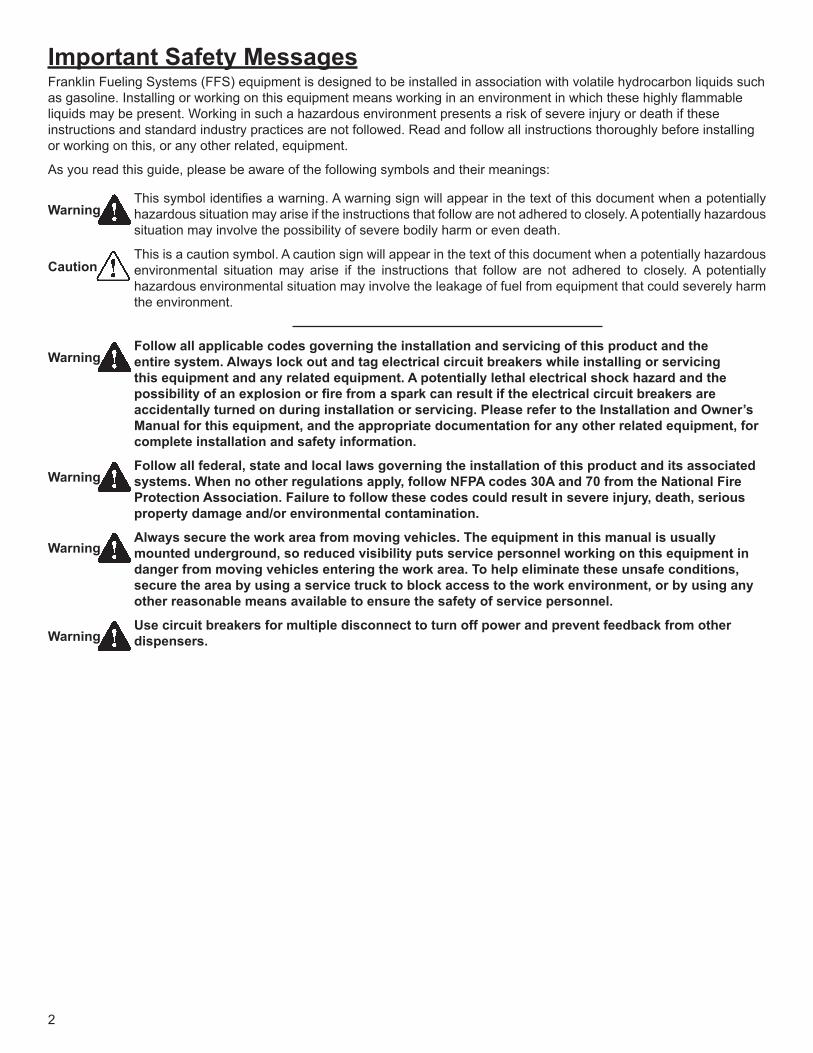
Important Safety MessagesFranklin Fueling Systems (FFS) equipment is designed to be installed in association with volatile hydrocarbon liquids such as gasoline. Installing or working on this equipment means working in an environment in which these highly flammable liquids may be present. Working in such a hazardous environment presents a risk of severe injury or death if these instructions and standard industry practices are not followed. Read and follow all instructions thoroughly before installing or working on this, or any other related, equipment.
As you read this guide, please be aware of the following symbols and their meanings:
This symbol identifies a warning. A warning sign will appear in the text of this document when a potentially hazardous situation may arise if the instructions that follow are not adhered to closely. A potentially hazardous situation may involve the possibility of severe bodily harm or even death.
This is a caution symbol. A caution sign will appear in the text of this document when a potentially hazardous environmental situation may arise if the instructions that follow are not adhered to closely. A potentially hazardous environmental situation may involve the leakage of fuel from equipment that could severely harm the environment.
Warning
Caution
Follow all applicable codes governing the installation and servicing of this product and the entire system. Always lock out and tag electrical circuit breakers while installing or servicing this equipment and any related equipment. A potentially lethal electrical shock hazard and the possibility of an explosion or fire from a spark can result if the electrical circuit breakers are accidentally turned on during installation or servicing. Please refer to the Installation and Owner’s Manual for this equipment, and the appropriate documentation for any other related equipment, for complete installation and safety information.
Follow all federal, state and local laws governing the installation of this product and its associated systems. When no other regulations apply, follow NFPA codes 30A and 70 from the National Fire Protection Association. Failure to follow these codes could result in severe injury, death, serious property damage and/or environmental contamination.
Always secure the work area from moving vehicles. The equipment in this manual is usually mounted underground, so reduced visibility puts service personnel working on this equipment in danger from moving vehicles entering the work area. To help eliminate these unsafe conditions, secure the area by using a service truck to block access to the work environment, or by using any other reasonable means available to ensure the safety of service personnel.
Use circuit breakers for multiple disconnect to turn off power and prevent feedback from other dispensers.
Warning
Warning
Warning
Warning
3
Contents
Important Safety Messages ............................................................................................2
Introduction ......................................................................................................................4Keywords/Definitions ..............................................................................................................4Description of Operation .........................................................................................................5Executive Orders ....................................................................................................................5
Installation ........................................................................................................................6Overview ................................................................................................................................6Tools Required ......................................................................................................................6
Vapor Return Piping Requirements ...............................................................................7Riser Pipe to Dispenser ..........................................................................................................7Gravity Drain Piping to UST ....................................................................................................7Vent Piping Requirements ......................................................................................................8Low Point Condensate Traps ................................................................................................ 11
VP500 Inlet & Outlet Port Requirements ..................................................................... 11Gravity Drain Requirements .................................................................................................12Low Point (Condensate Trap) Requirements ........................................................................13
VP500B / VP500ATXF Series Vacuum Source Installation .........................................1410 Fueling Position Capacity with 5 Nozzles in Simultaneous Flow ..................................... 14
Dispenser Vapor Piping Requirements .......................................................................16Whip Hoses ..........................................................................................................................16
Electrical Requirements................................................................................................18
Maintenance and Testing ..............................................................................................19Testing ..................................................................................................................................19Maintenance .........................................................................................................................19
4
IntroductionThis manual describes the tools and methods required to install a FFS / Healy Systems Model VP500 Series vacuum source and related components. The installer must be a skilled petroleum technician, thoroughly familiar with all federal, state, and local codes and requirements within the area of the installation. He or she must also take all the necessary safety precautions and requirements to assure a safe installation environment.
Keywords/Definitions
A/L = Air to Liquid ratio An air over liquid ratio used to measure the volume of air returned to a storage tank when a specific volume of gasoline is dispensed through a vapor recovery system.
AST = Aboveground Storage Tank An AST is where product is stored at a facility in a storage tank aboveground.
CARB = California Air Resources Board The California government agency that sets regulations for vapor recovery systems.
Check Valve A mechanical device that normally allows fluid to flow through it in only one direction.
Condensate Trap The low point in a vapor line where liquid may be present.
EO = Executive Order A legal document created by CARB which defines in great detail all the approved parts, testing procedures and vapor recovery specifications.
Hanging Hardware The components needed on the outside of a dispenser for a Healy vac-assist vapor recovery system. This in-cludes whip hose, breakaway, coaxial hose, and nozzle.
Inches Water Column (WC) The measurement we will be using for the Healy system to monitor negative and positive pressures.
Inverted Coaxial Hose An inner hose is installed within a typical ¾” hose. With an assist system coaxial hose the inner hose collects vapors and the surrounding outer hose will have product flowing through to the nozzle. This is inverted from a balance system coaxial hose, which uses the inner hose for product flow.
Stage I Vapor Recovery The collection of vapors during storage tank deliveries.
Stage II Vapor Recovery The collection of vapors during vehicle refueling.
Splitter Valve A Healy part that separates the product and vapor paths.
STP = Submerged Turbine Pump Consists of three major parts, the manifold, extractable, and pump motor assembly (PMA). The PMA picks up fuel from the storage tank, sends it through the extractable into the manifold, and into the pipeline.
Suction Pump A pump for drawing up a liquid by means of suction produced by a piston drawn through a cylinder.
UST = Underground Storage Tank An UST is where product is stored at a facility in a storage tank underground.
Vacuum Source The mechanical or electrical device that assists in returning vapors back to the storage tank.
5
Description of OperationThe VP500 series is used to supply vacuum to the vapor return piping, dispenser vapor piping and hanging hardware / nozzle. These three sections of piping are interconnected to form a vapor return system that can supply up to 20 fueling points.
The VP500 starts whenever a fueling point has been authorized and maintains a constant regulated vacuum of 65" to 85" WC to each fueling point in the system.
The Healy Systems VP500 Series Vacuum Source is available in three configurations and is operated as a central component of a Healy Stage II system. The vacuum source can be installed in close proximity to the storage tanks, vent lines or can be put in a central location.
To activate, the VP500 receives a signal from a STP/Suction Pump relay or other contact point used to energize the fuel supply system. When supplied with the proper amount of vacuum and product pressure, each nozzle (fueling point) will individually regulate the volume of vapor returned versus the volume of liquid (gasoline) dispensed through the nozzle.
Executive OrdersThe VP500 is listed in three CARB Executive Orders for use on Underground and Aboveground Storage Tank applications.
• G-70-165 Is certified for UST applications using the Healy Model 600 nozzle.• G-70-186
Is certified for UST applications using the Healy Model 400 nozzle.• G-70-187
Is certified for AST applications using the Healy Model 400 nozzle.
6
Installation
Overview The VP500 central vacuum system can be installed only in facilities which conform to, and are capable of demonstrating compliance with, vapor line integrity, leak, and blockage testing as described in this manual. The system will be operated in accordance with manufacturer specifications and requirements for installation and maintenance. Installing contractors are responsible for the connecting pipe, fittings, and components not described in the system equipment list purchased for the site.
Tools Required • 0-100" Water Column Vacuum Gage • 1/2" or 3/8" Ratchet set w/Sockets 1/4" through 9/16" + 3" Extension• 9" Lineman’s Pliers• Assorted Open End Wrenches 1/4" through 3/4"• Assorted Allen Wrenches• Wire Cutters/Strippers 18 AWG and 26 AWG• 3/8" Drill Assembly• Assorted Drill Bits 1/16" through 7/16"• Assorted Screwdrivers • 1/2" (5/8" O.D.) Copper Tube Bending Tool• 1/2" (5/8" O.D.) Copper Flaring Tool• Copper Tubing Cutter• Electrical Multi-meter• 12" adjustable Wrench• 18" Channel lock Pliers• (2) 18" Pipe Wrench• Pipe Threader (for up to 3" pipe)• Pipe Cutter (for up to 3" pipe)• Tape Measure• PTFE Pipe Tape• Thread Sealing Compound
7
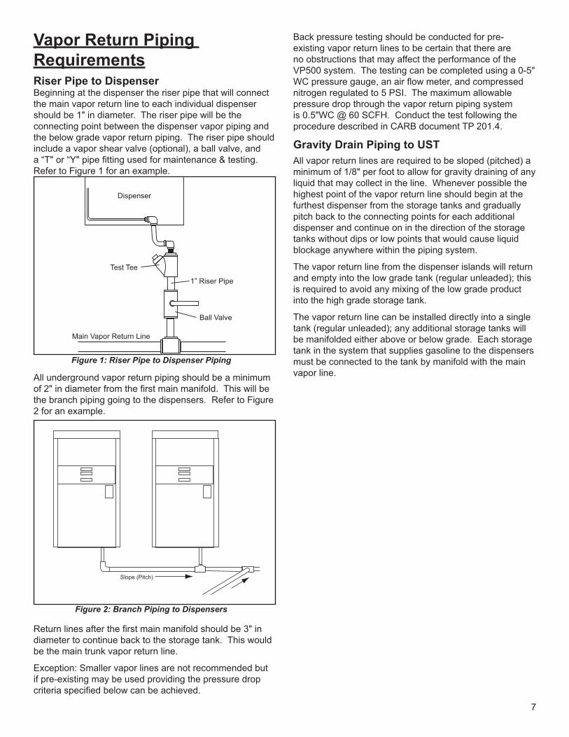
Vapor Return Piping RequirementsRiser Pipe to DispenserBeginning at the dispenser the riser pipe that will connect the main vapor return line to each individual dispenser should be 1" in diameter. The riser pipe will be the connecting point between the dispenser vapor piping and the below grade vapor return piping. The riser pipe should include a vapor shear valve (optional), a ball valve, and a “T" or “Y" pipe fitting used for maintenance & testing. Refer to Figure 1 for an example.
All underground vapor return piping should be a minimum of 2" in diameter from the first main manifold. This will be the branch piping going to the dispensers. Refer to Figure 2 for an example.
Return lines after the first main manifold should be 3" in diameter to continue back to the storage tank. This would be the main trunk vapor return line.
Exception: Smaller vapor lines are not recommended but if pre-existing may be used providing the pressure drop criteria specified below can be achieved.
Back pressure testing should be conducted for pre-existing vapor return lines to be certain that there are no obstructions that may affect the performance of the VP500 system. The testing can be completed using a 0-5" WC pressure gauge, an air flow meter, and compressed nitrogen regulated to 5 PSI. The maximum allowable pressure drop through the vapor return piping system is 0.5"WC @ 60 SCFH. Conduct the test following the procedure described in CARB document TP 201.4.
Gravity Drain Piping to USTAll vapor return lines are required to be sloped (pitched) a minimum of 1/8" per foot to allow for gravity draining of any liquid that may collect in the line. Whenever possible the highest point of the vapor return line should begin at the furthest dispenser from the storage tanks and gradually pitch back to the connecting points for each additional dispenser and continue on in the direction of the storage tanks without dips or low points that would cause liquid blockage anywhere within the piping system.
The vapor return line from the dispenser islands will return and empty into the low grade tank (regular unleaded); this is required to avoid any mixing of the low grade product into the high grade storage tank.
The vapor return line can be installed directly into a single tank (regular unleaded); any additional storage tanks will be manifolded either above or below grade. Each storage tank in the system that supplies gasoline to the dispensers must be connected to the tank by manifold with the main vapor line.
Figure 1: Riser Pipe to Dispenser Piping
Dispenser
Test Tee
1” Riser Pipe
Ball Valve
Main Vapor Return Line
Figure 2: Branch Piping to Dispensers
Slope (Pitch)
8
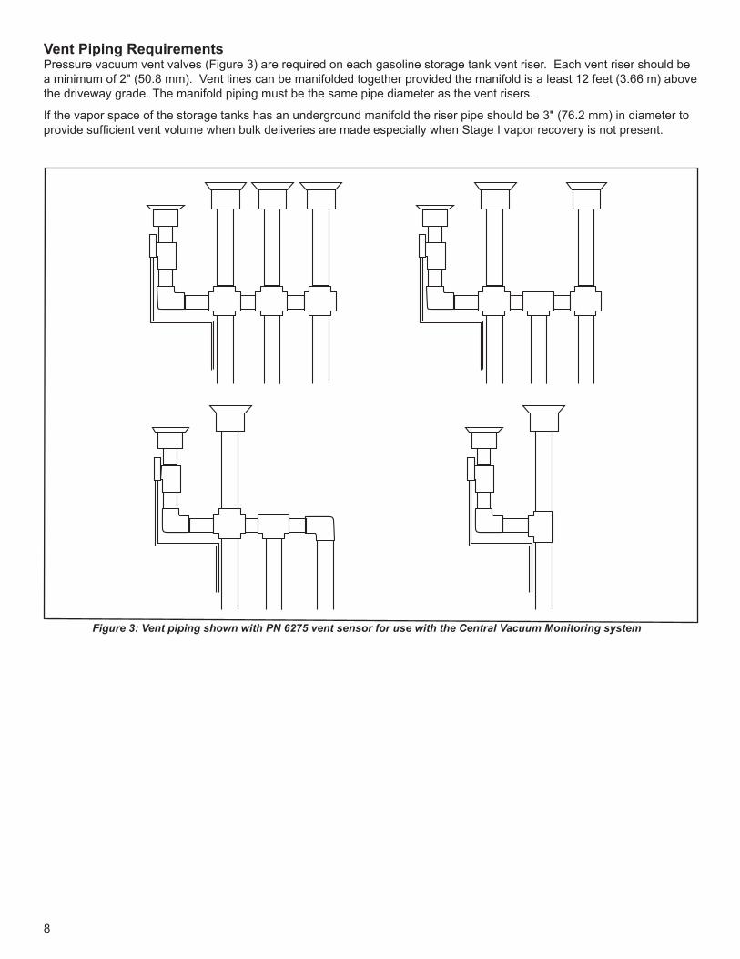
Vent Piping RequirementsPressure vacuum vent valves (Figure 3) are required on each gasoline storage tank vent riser. Each vent riser should be a minimum of 2" (50.8 mm). Vent lines can be manifolded together provided the manifold is a least 12 feet (3.66 m) above the driveway grade. The manifold piping must be the same pipe diameter as the vent risers.
If the vapor space of the storage tanks has an underground manifold the riser pipe should be 3" (76.2 mm) in diameter to provide sufficient vent volume when bulk deliveries are made especially when Stage I vapor recovery is not present.
Figure 3: Vent piping shown with PN 6275 vent sensor for use with the Central Vacuum Monitoring system
9
Vapor Return Piping Requirements (continued)
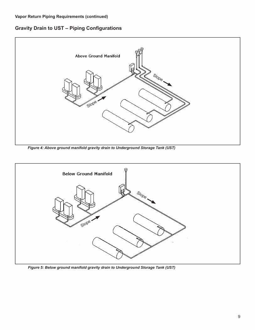
Gravity Drain to UST – Piping Configurations
Figure 4: Above ground manifold gravity drain to Underground Storage Tank (UST)
Slope
Slope
Figure 5: Below ground manifold gravity drain to Underground Storage Tank (UST)
Slope
Slope
10
Vapor Return Piping Requirements (continued)
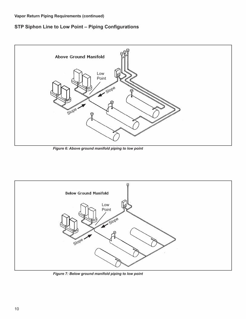
STP Siphon Line to Low Point – Piping Configurations
Figure 6: Above ground manifold piping to low point
Figure 7: Below ground manifold piping to low point
Slope
Slope
Low Point
Slope
Slope
Low Point
11
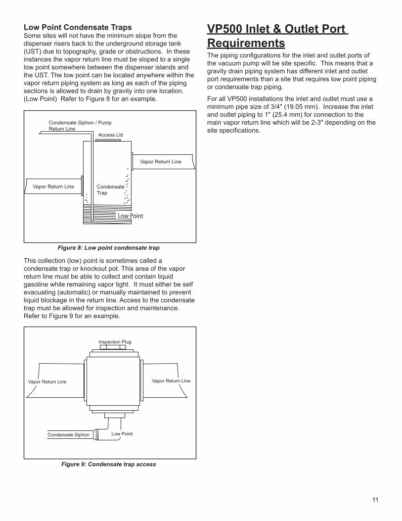
Low Point Condensate TrapsSome sites will not have the minimum slope from the dispenser risers back to the underground storage tank (UST) due to topography, grade or obstructions. In these instances the vapor return line must be sloped to a single low point somewhere between the dispenser islands and the UST. The low point can be located anywhere within the vapor return piping system as long as each of the piping sections is allowed to drain by gravity into one location. (Low Point) Refer to Figure 8 for an example.
This collection (low) point is sometimes called a condensate trap or knockout pot. This area of the vapor return line must be able to collect and contain liquid gasoline while remaining vapor tight. It must either be self evacuating (automatic) or manually maintained to prevent liquid blockage in the return line. Access to the condensate trap must be allowed for inspection and maintenance. Refer to Figure 9 for an example.
VP500 Inlet & Outlet Port RequirementsThe piping configurations for the inlet and outlet ports of the vacuum pump will be site specific. This means that a gravity drain piping system has different inlet and outlet port requirements than a site that requires low point piping or condensate trap piping.
For all VP500 installations the inlet and outlet must use a minimum pipe size of 3/4" (19.05 mm). Increase the inlet and outlet piping to 1" (25.4 mm) for connection to the main vapor return line which will be 2-3" depending on the site specifications.
Low Point
Vapor Return Line
Vapor Return Line
CondensateTrap
Access Lid
Condensate Siphon / PumpReturn Line
Figure 8: Low point condensate trap
Vapor Return LineVapor Return Line
Low PointCondensate Siphon
Inspection Plug
Figure 9: Condensate trap access
12
Gravity Drain RequirementsSites with gravity drain piping have a specific installation method. The installation must allow the site to achieve full vacuum for the vapor return line and also allow any liquid condensate that has collected in that return line to drain back to the storage tank when vacuum pressure is not present.
Piping slope (pitch) must be maintained for all the vapor return lines from each dispenser. The slope must be maintained back to the location of the VP500 and then continue to the storage tank.
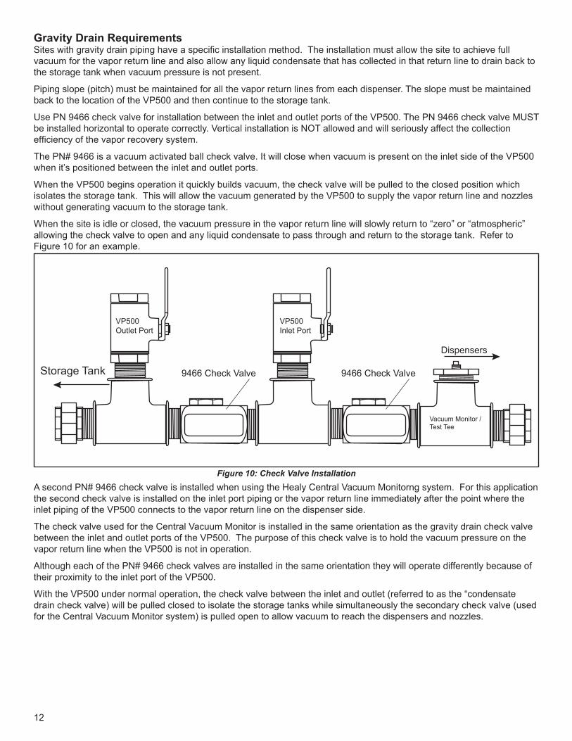
Use PN 9466 check valve for installation between the inlet and outlet ports of the VP500. The PN 9466 check valve MUST be installed horizontal to operate correctly. Vertical installation is NOT allowed and will seriously affect the collection efficiency of the vapor recovery system.
The PN# 9466 is a vacuum activated ball check valve. It will close when vacuum is present on the inlet side of the VP500 when it’s positioned between the inlet and outlet ports.
When the VP500 begins operation it quickly builds vacuum, the check valve will be pulled to the closed position which isolates the storage tank. This will allow the vacuum generated by the VP500 to supply the vapor return line and nozzles without generating vacuum to the storage tank.
When the site is idle or closed, the vacuum pressure in the vapor return line will slowly return to “zero” or “atmospheric” allowing the check valve to open and any liquid condensate to pass through and return to the storage tank. Refer to Figure 10 for an example.
Storage Tank 9466 Check Valve
Dispensers
9466 Check Valve
VP500Outlet Port
VP500Inlet Port
Vacuum Monitor / Test Tee
Figure 10: Check Valve InstallationA second PN# 9466 check valve is installed when using the Healy Central Vacuum Monitorng system. For this application the second check valve is installed on the inlet port piping or the vapor return line immediately after the point where the inlet piping of the VP500 connects to the vapor return line on the dispenser side.
The check valve used for the Central Vacuum Monitor is installed in the same orientation as the gravity drain check valve between the inlet and outlet ports of the VP500. The purpose of this check valve is to hold the vacuum pressure on the vapor return line when the VP500 is not in operation.
Although each of the PN# 9466 check valves are installed in the same orientation they will operate differently because of their proximity to the inlet port of the VP500.
With the VP500 under normal operation, the check valve between the inlet and outlet (referred to as the “condensate drain check valve) will be pulled closed to isolate the storage tanks while simultaneously the secondary check valve (used for the Central Vacuum Monitor system) is pulled open to allow vacuum to reach the dispensers and nozzles.
13
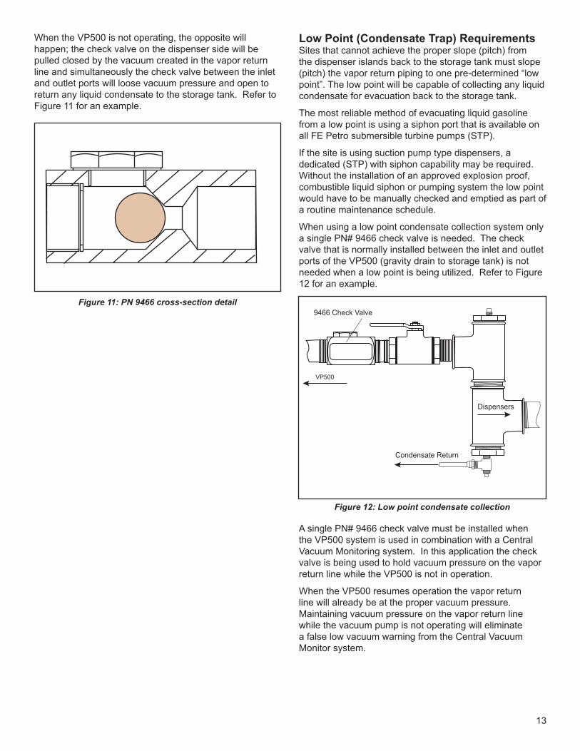
When the VP500 is not operating, the opposite will happen; the check valve on the dispenser side will be pulled closed by the vacuum created in the vapor return line and simultaneously the check valve between the inlet and outlet ports will loose vacuum pressure and open to return any liquid condensate to the storage tank. Refer to Figure 11 for an example.
Low Point (Condensate Trap) RequirementsSites that cannot achieve the proper slope (pitch) from the dispenser islands back to the storage tank must slope (pitch) the vapor return piping to one pre-determined “low point”. The low point will be capable of collecting any liquid condensate for evacuation back to the storage tank.
The most reliable method of evacuating liquid gasoline from a low point is using a siphon port that is available on all FE Petro submersible turbine pumps (STP).
If the site is using suction pump type dispensers, a dedicated (STP) with siphon capability may be required. Without the installation of an approved explosion proof, combustible liquid siphon or pumping system the low point would have to be manually checked and emptied as part of a routine maintenance schedule.
When using a low point condensate collection system only a single PN# 9466 check valve is needed. The check valve that is normally installed between the inlet and outlet ports of the VP500 (gravity drain to storage tank) is not needed when a low point is being utilized. Refer to Figure 12 for an example.
A single PN# 9466 check valve must be installed when the VP500 system is used in combination with a Central Vacuum Monitoring system. In this application the check valve is being used to hold vacuum pressure on the vapor return line while the VP500 is not in operation.
When the VP500 resumes operation the vapor return line will already be at the proper vacuum pressure. Maintaining vacuum pressure on the vapor return line while the vacuum pump is not operating will eliminate a false low vacuum warning from the Central Vacuum Monitor system.
Figure 11: PN 9466 cross-section detail
Condensate Return
Dispensers
9466 Check Valve
VP500
Figure 12: Low point condensate collection
14
VP500B / VP500ATXF Series Vacuum Source Installation
10 Fueling Position Capacity with 5 Nozzles in Simultaneous Flow
The VP500B / VP500ATXF vacuum pump kits includes:
• 1 Vacuum Pump Assembly• 1 Heavy-Duty Angle Bracket• 1 Hardware Kit• 1 Explosion Proof Junction Box• 2 U-Bolts w/ Washers & Hex Nuts
The VP500 is most often installed in close proximity to the storage tank adjacent to the vapor return line. The preferred installation is inside a storage tank sump or other protected area with easy access to the vapor piping. Use of the heavy-duty angle bracket is recommended to support the weight and vibration of the vacuum source.
The mounting bracket should be securely fastened by the two U-Bolts supplied with the kit. The hardware is designed to clamp on to a rigid 4" riser pipe capable of supporting the vacuum pump and bracket. When a riser pipe is not available, the angle bracket should be bolted to a permanent steel plate or concrete structure to support the vacuum pumps weight and vibration while in operation.
Before mounting the vacuum pump, make certain that there is sufficient space around the unit to allow for inlet and outlet piping configurations and electrical junction box requirements described in this manual.
The installer should include two pieces of steel braided flex hose with a minimum of 3/4" I.D for the inlet and outlet connections between the VP500 and the main vapor return line (See Figure 13). Use of flex hose will insure that the vapor return line and vacuum source do not experience unnecessary vibration and torque after installation.
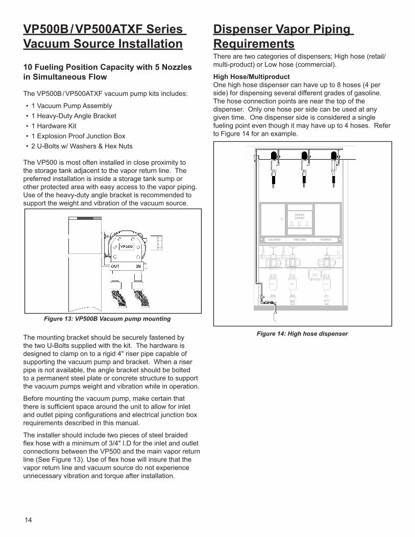
Dispenser Vapor Piping RequirementsThere are two categories of dispensers; High hose (retail/multi-product) or Low hose (commercial).
High Hose/MultiproductOne high hose dispenser can have up to 8 hoses (4 per side) for dispensing several different grades of gasoline. The hose connection points are near the top of the dispenser. Only one hose per side can be used at any given time. One dispenser side is considered a single fueling point even though it may have up to 4 hoses. Refer to Figure 14 for an example.
Figure 14: High hose dispenser
Figure 13: VP500B Vacuum pump mounting
15
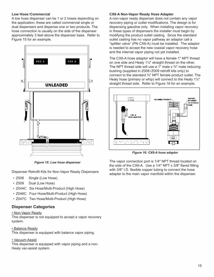
Low Hose / Commercial A low hose dispenser can be 1 or 2 hoses depending on the application; these are called commercial single or dual dispensers and dispense one or two products. The hose connection is usually on the side of the dispenser approximately 3 feet above the dispenser base. Refer to Figure 15 for an example.
Figure 15: Low hose dispenser
Dispenser Retrofit Kits for Non-Vapor Ready Dispensers
• Z008 Single (Low Hose)• Z009 Dual (Low Hose)• Z044C Six Hose/Multi-Product (High Hose)• Z046C Four Hose/Multi-Product (High Hose)• Z047C Two Hose/Multi-Product (High Hose)
Dispenser Categories• Non-Vapor ReadyThis dispenser is not equipped to accept a vapor recovery system.
• Balance ReadyThis dispenser is equipped with balance vapor piping.
• Vacuum AssistThis dispenser is equipped with vapor piping and a non-Healy vac-assist system.
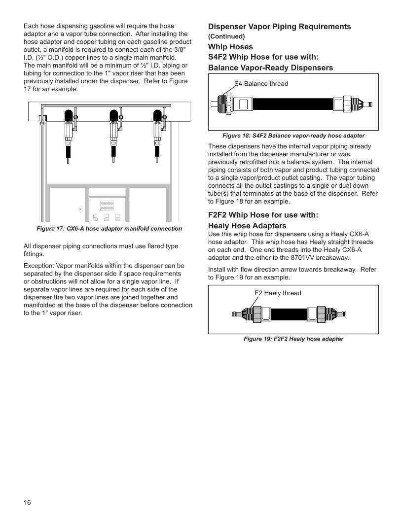
CX6-A Non-Vapor Ready Hose AdapterA non-vapor ready dispenser does not contain any vapor recovery piping or outlet modifications. The design is for dispensing gasoline only. When installing vapor recovery in these types of dispensers the installer must begin by modifying the product outlet casting. Since the standard outlet casting has no vapor pathway an adaptor call a “splitter valve” (PN CX6-A) must be installed. The adaptor is needed to accept the new coaxial vapor recovery hose and the internal vapor piping not yet installed.
The CX6-A hose adaptor will have a female 1" NPT thread on one side and Healy 1¼" straight thread on the other. The NPT thread side will use a 1" male x ¾" male reducing bushing (supplied in Z008 / Z009 retrofit kits only) to connect to the standard ¾" NPT female product outlet. The Healy hose (primary or whip) will connect to the Healy 1¼" straight thread side. Refer to Figure 16 for an example.
Figure 16: CX6-A hose adaptor
The vapor connection port is 1/4" NPT thread located on the side of the CX6-A. Use a 1/4" NPT x 3/8" flared fitting with 3/8" I.D. flexible copper tubing to connect the hose adapter to the main vapor manifold within the dispenser.
16
Each hose dispensing gasoline will require the hose adaptor and a vapor tube connection. After installing the hose adaptor and copper tubing on each gasoline product outlet, a manifold is required to connect each of the 3/8" I.D. (½" O.D.) copper lines to a single main manifold. The main manifold will be a minimum of ½" I.D. piping or tubing for connection to the 1" vapor riser that has been previously installed under the dispenser. Refer to Figure 17 for an example.
Figure 17: CX6-A hose adaptor manifold connection
All dispenser piping connections must use flared type fittings.
Exception: Vapor manifolds within the dispenser can be separated by the dispenser side if space requirements or obstructions will not allow for a single vapor line. If separate vapor lines are required for each side of the dispenser the two vapor lines are joined together and manifolded at the base of the dispenser before connection to the 1" vapor riser.
Dispenser Vapor Piping Requirements (Continued)Whip HosesS4F2 Whip Hose for use with:Balance Vapor-Ready Dispensers
Figure 18: S4F2 Balance vapor-ready hose adapter
S4 Balance thread
These dispensers have the internal vapor piping already installed from the dispenser manufacturer or was previously retrofitted into a balance system. The internal piping consists of both vapor and product tubing connected to a single vapor/product outlet casting. The vapor tubing connects all the outlet castings to a single or dual down tube(s) that terminates at the base of the dispenser. Refer to Figure 18 for an example.
F2F2 Whip Hose for use with:Healy Hose AdaptersUse this whip hose for dispensers using a Healy CX6-A hose adaptor. This whip hose has Healy straight threads on each end. One end threads into the Healy CX6-A adaptor and the other to the 8701VV breakaway.
Install with flow direction arrow towards breakaway. Refer to Figure 19 for an example.
Figure 19: F2F2 Healy hose adapter
F2 Healy thread
17
F3F2 Whip Hose for use with:OEM Vacuum Assist to Healy Vacuum Assist
These dispensers contain a vacuum assist system installed by the dispenser manufacturer. To retrofit the dispenser to a Healy vacuum assist system, use this adapting whip hose to convert the OEM hanging hardware to Healy hanging hardware. OEM vacuum system removal and vapor piping modifications will be required. Refer to Figure 20 for an example.
Figure 20: F3F2 OEM Metric to Healy hose adapter
F3 Metric thread
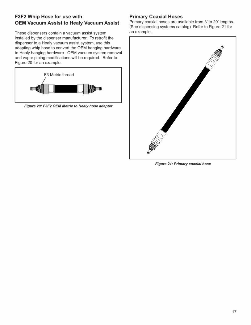
Primary Coaxial HosesPrimary coaxial hoses are available from 3’ to 20’ lengths. (See dispensing systems catalog) Refer to Figure 21 for an example.
Figure 21: Primary coaxial hose
18
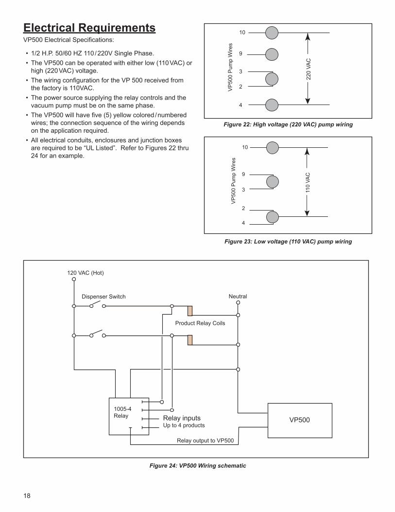
Electrical RequirementsVP500 Electrical Specifications:
• 1/2 H.P. 50/60 HZ 110 / 220V Single Phase. • The VP500 can be operated with either low (110 VAC) or
high (220 VAC) voltage.• The wiring configuration for the VP 500 received from
the factory is 110VAC. • The power source supplying the relay controls and the
vacuum pump must be on the same phase.• The VP500 will have five (5) yellow colored / numbered
wires; the connection sequence of the wiring depends on the application required.
• All electrical conduits, enclosures and junction boxes are required to be “UL Listed”. Refer to Figures 22 thru 24 for an example.
220
VAC
VP
500
Pum
p W
ires
10
9
3
2
4
Figure 22: High voltage (220 VAC) pump wiring
110
VAC
VP
500
Pum
p W
ires
10
9
3
2
4
Figure 23: Low voltage (110 VAC) pump wiring
VP500Relay inputsUp to 4 products
Neutral
Product Relay Coils
1005-4Relay
120 VAC (Hot)
Dispenser Switch
Relay output to VP500
Figure 24: VP500 Wiring schematic
19
Maintenance and TestingTestingThis equipment should only be installed at facilities capable of demonstrating compliance with the California Air Resources Board (CARB) vapor recovery performance tests:
Go to the CARB web site for complete methods of the test procedures listed below:
TP 201.3 2" W.C. Static pressure performance test
TP 201.4 Dynamic Back Pressure Test
TP 201.5 Air to Liquid Volume Test
Perform these tests only after the completed installation of the VP500 vapor recovery system. These tests will ensure the proper efficiency and trouble free operation of the system.
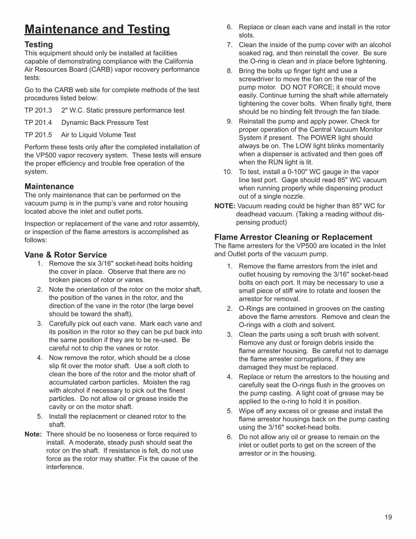
MaintenanceThe only maintenance that can be performed on the vacuum pump is in the pump’s vane and rotor housing located above the inlet and outlet ports.
Inspection or replacement of the vane and rotor assembly, or inspection of the flame arrestors is accomplished as follows:
Vane & Rotor Service 1. Remove the six 3/16" socket-head bolts holding
the cover in place. Observe that there are no broken pieces of rotor or vanes.
2. Note the orientation of the rotor on the motor shaft, the position of the vanes in the rotor, and the direction of the vane in the rotor (the large bevel should be toward the shaft).
3. Carefully pick out each vane. Mark each vane and its position in the rotor so they can be put back into the same position if they are to be re-used. Be careful not to chip the vanes or rotor.
4. Now remove the rotor, which should be a close slip fit over the motor shaft. Use a soft cloth to clean the bore of the rotor and the motor shaft of accumulated carbon particles. Moisten the rag with alcohol if necessary to pick out the finest particles. Do not allow oil or grease inside the cavity or on the motor shaft.
5. Install the replacement or cleaned rotor to the shaft.
Note: There should be no looseness or force required to install. A moderate, steady push should seat the rotor on the shaft. If resistance is felt, do not use force as the rotor may shatter. Fix the cause of the interference.
6. Replace or clean each vane and install in the rotor slots.
7. Clean the inside of the pump cover with an alcohol soaked rag, and then reinstall the cover. Be sure the O-ring is clean and in place before tightening.
8. Bring the bolts up finger tight and use a screwdriver to move the fan on the rear of the pump motor. DO NOT FORCE; it should move easily. Continue turning the shaft while alternately tightening the cover bolts. When finally tight, there should be no binding felt through the fan blade.
9. Reinstall the pump and apply power. Check for proper operation of the Central Vacuum Monitor System if present. The POWER light should always be on. The LOW light blinks momentarily when a dispenser is activated and then goes off when the RUN light is lit.
10. To test, install a 0-100" WC gauge in the vapor line test port. Gage should read 85" WC vacuum when running properly while dispensing product out of a single nozzle.
NOTE: Vacuum reading could be higher than 85" WC for deadhead vacuum. (Taking a reading without dis-pensing product)
Flame Arrestor Cleaning or ReplacementThe flame arresters for the VP500 are located in the Inlet and Outlet ports of the vacuum pump.
1. Remove the flame arrestors from the inlet and outlet housing by removing the 3/16" socket-head bolts on each port. It may be necessary to use a small piece of stiff wire to rotate and loosen the arrestor for removal.
2. O-Rings are contained in grooves on the casting above the flame arrestors. Remove and clean the O-rings with a cloth and solvent.
3. Clean the parts using a soft brush with solvent. Remove any dust or foreign debris inside the flame arrester housing. Be careful not to damage the flame arrester corrugations, if they are damaged they must be replaced.
4. Replace or return the arrestors to the housing and carefully seat the O-rings flush in the grooves on the pump casting. A light coat of grease may be applied to the o-ring to hold it in position.
5. Wipe off any excess oil or grease and install the flame arrestor housings back on the pump casting using the 3/16" socket-head bolts.
6. Do not allow any oil or grease to remain on the inlet or outlet ports to get on the screen of the arrestor or in the housing.
20
After maintenance has been completed the VP500 must be tested to ensure the pump is operating at the proper vacuum levels.
Install a 0-100" WC gauge in the vapor line testing port located on the vapor return line. With the system activated the vacuum pressure should be approximately 80" WC. The systems operating range is from 65" to 85" WC depending upon the amount of customers fueling at the site.
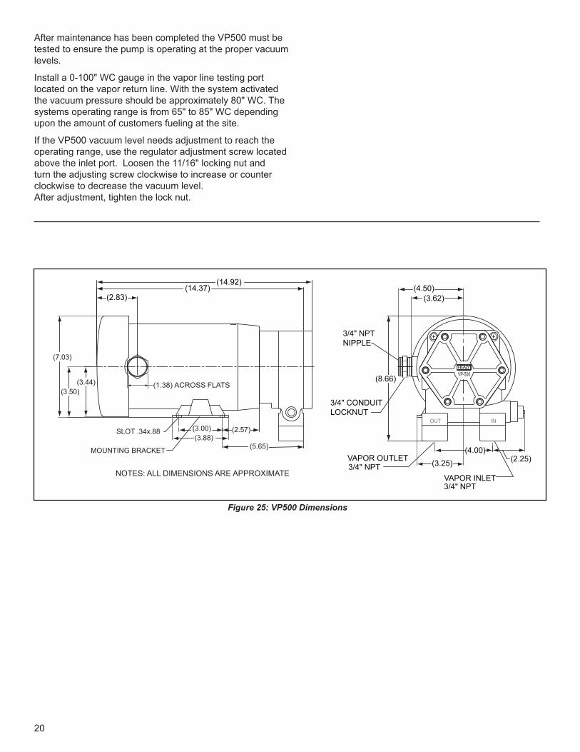
If the VP500 vacuum level needs adjustment to reach the operating range, use the regulator adjustment screw located above the inlet port. Loosen the 11/16" locking nut and turn the adjusting screw clockwise to increase or counter clockwise to decrease the vacuum level. After adjustment, tighten the lock nut.
(14.37)
(3.44)(3.50)
(2.83)
(7.03)
(4.50)(3.62)
(8.66)
(3.25)(4.00)
(2.25)
NOTES: ALL DIMENSIONS ARE APPROXIMATE
(14.92)
INOUT
AHE LYVP-500
VAPOR INLET3/4" NPT
VAPOR OUTLET3/4" NPT
SLOT .34x.88
MOUNTING BRACKET
(3.00)(3.88)
(2.57)
(5.65)
3/4" CONDUIT LOCKNUT
3/4" NPT NIPPLE
(1.38) ACROSS FLATS
Figure 25: VP500 Dimensions

21
Notes
SITE NAME:
ADDRESS:
DATE INSTALLED:
INSTALLING CONTRACTOR:
SERVICE CONTACT:
SERVICE TELEPHONE #:
www.franklinfueling.com ©2016 FFS 405116001 Rev.4
For future reference