Embed Size (px)
Citation preview
Publ. 1 - AM0701 - A 11 / 98 / 2000 / FB Replaces : 1 - AM 075 - A
Vane pumps
single, double & triple
T6 mobile application
CONTENTS - T6 SERIES MOBILE APPLICATION
Features........................................................................................................................... 3Instructions ..................................................................................................................... 3Minimum & maximum speeds ....................................................................................... 4Pressure ratings............................................................................................................... 4Priming at starting........................................................................................................... 4Minimum allowable inlet pressure ................................................................................. 5General characteristics.................................................................................................... 5Pump selection : Routine and example .......................................................................... 6Intermittent pressure rating............................................................................................. 6Description...................................................................................................................... 7Application advantages................................................................................................... 7Shafts and hydraulic fluids ............................................................................................. 8Notes ............................................................................................................................... 9
Ordering code & Technical data................................................................................... 10Dimensions & Operating characteristics ...................................................................... 11
Ordering code & Technical data................................................................................... 12Dimensions & Operating characteristics ...................................................................... 13
Ordering code & Technical data................................................................................... 14Dimensions & Operating characteristics ...................................................................... 15
Ordering code & Technical data................................................................................... 16Dimensions & Operating characteristics ...................................................................... 17
Ordering code & Technical data................................................................................... 18Dimensions & Operating characteristics ...................................................................... 19
Ordering code & Technical data................................................................................... 20Dimensions & Operating characteristics ...................................................................... 21
Ordering code & Technical data................................................................................... 22Dimensions & Operating characteristics ...................................................................... 23
Ordering code & Technical data................................................................................... 24Dimensions & Operating characteristics ...................................................................... 25
Ordering code & Operating characteristics ................................................................. 26Dimensions ................................................................................................................... 27Technical data ............................................................................................................... 28
Technical data ............................................................................................................... 29Dimensions T6EDCM .................................................................................................. 30Dimensions T6EDCS ................................................................................................... 31Ordering code & Operating characteristics .................................................................. 32
Additional shafts........................................................................................................... 33Porting diagrams for double pumps ............................................................................. 34Porting diagrams for triple pumps........................................................................ 34 - 35
GENERAL
T6CM
T6CP
T6D*
T6E*
T6CC*
T6DC*
T6EC*
T6ED*
T6DCCM
T6EDC*
2Parker Hannifin
Denison Vane Pump DivisionVierzon - France
FEATURES - T6 SERIES MOBILE APPLICATION
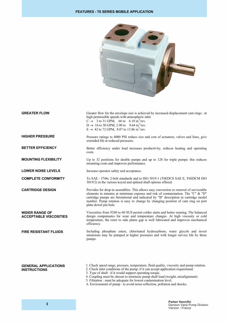
Greater flow for the envelope size is achieved by increased displacement cam rings : athigh permissible speeds with atmospheric inlet
C ! 3 to 31 GPM, .66 to 6.10 in3/rev.
D !" 14 to 50 GPM, 2.90 to 9.64 in3/rev.
E !""42 to 72 GPM, 8.07 to 13.86 in3/rev.
Pressure ratings to 4000 PSI reduce size and cost of actuators, valves and lines, giveextended life at reduced pressures.
Better efficiency under load increases productivity, reduces heating and operatingcosts.
Up to 32 positions for double pumps and up to 128 for triple pumps: this reducesmounting costs and improves performance.
Increase operator safety and acceptance.
To SAE - J744c 2-bolt standards and to ISO 3019-1 (T6EDCS SAE E, T6EDCM ISO3019/2) in the various keyed and splined shaft options offered.
Provides for drop-in assemblies. This allows easy conversion or renewal of serviceableelements in minutes at minimum expense and risk of contamination. The "C" & "D"cartridge pumps are birotational and indicated by "B" description in cartridge modelnumber. Pump rotation is easy to change by changing position of cam ring on portplate dowel pin hole.
Viscosities from 9240 to 60 SUS permit colder starts and hotter running. The balanceddesign compensates for wear and temperature changes. At high viscosity or coldtemperature, the rotor to side plates gap is well lubricated and improves mechanicalefficiency.
Including phosphate esters, chlorinated hydrocarbons, water glycols and invertemulsions may be pumped at higher pressures and with longer service life by thesepumps.
1. Check speed range, pressure, temperature, fluid quality, viscosity and pump rotation.2. Check inlet conditions of the pump, if it can accept application requirement.3. Type of shaft : if it would support operating torque.4. Coupling must be chosen to minimize pump shaft load (weight, misalignment).5. Filtration : must be adequate for lowest contamination level.6. Environment of pump : to avoid noise reflection, pollution and shocks.
GREATER FLOW
HIGHER PRESSURE
BETTER EFFICIENCY
MOUNTING FLEXIBILITY
LOWER NOISE LEVELS
COMPLETE CONFORMITY
CARTRIDGE DESIGN
WIDER RANGE OF
ACCEPTABLE VISCOSITIES
FIRE RESISTANT FLUIDS
GENERAL APPLICATIONS
INSTRUCTIONS
3Parker Hannifin
Denison Vane Pump DivisionVierzon - France
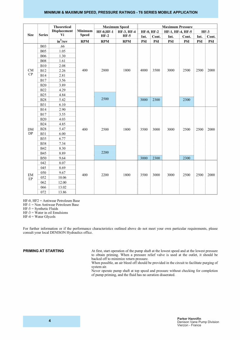
MINIMUM & MAXIMUM SPEED, PRESSURE RATINGS - T6 SERIES MOBILE APPLICATION
Size Series
TheoreticalDisplacement
ViMinimum
Speed
Maximum Speed Maximum Pressure
HF-0,HF-1HF-2
HF-3, HF-4HF-5
HF-0, HF-2 HF-1, HF-4, HF-5 HF-3
Int. Cont. Int. Cont. Int. Cont.
in3/rev RPM RPM RPM PSI PSI PSI PSI PSI PSI
CMCP
B03 .66
400 2800 1800 4000 3500 3000 2500 2500 2000
B05 1.05
B06 1.30
B08 1.61
B10 2.08
B12 2.26
B14 2.81
B17 3.56
B20 3.89
B22 4.29
B25 4.842500B28 5.42 3000 2300 2300
B31 6.10
DMDP
B14 2.90
400 2500 1800 3500 3000 3000 2500 2500 2000
B17 3.55
B20 4.03
B24 4.85
B28 5.47
B31 6.00
B35 6.77
B38 7.34
B42 8.302200B45 8.89
B50 9.64 3000 2300 2300
EMEP
042 8.07
400 2200 1800 3500 3000 3000 2500 2500 2000
045 8.69
050 9.67
052 10.06
062 12.00
066 13.02
072 13.86
HF-0, HF2 = Antiwear Petroleum BaseHF-1 = Non Antiwear Petroleum BaseHF-5 = Synthetic FluidsHF-3 = Water in oil EmulsionsHF-4 = Water Glycols
For further information or if the performance characteristics outlined above do not meet your own particular requirements, pleaseconsult your local DENISON Hydraulics office.
At first, start operation of the pump shaft at the lowest speed and at the lowest pressureto obtain priming. When a pressure relief valve is used at the outlet, it should bebacked off to minimize return pressure.When possible, an air bleed off should be provided in the circuit to facilitate purging ofsystem air.Never operate pump shaft at top speed and pressure without checking for completionof pump priming, and the fluid has no aeration disaerated.
PRIMING AT STARTING
4Parker Hannifin
Denison Vane Pump DivisionVierzon - France
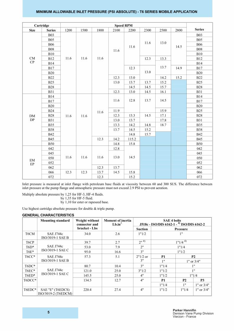
MINIMUM ALLOWABLE INLET PRESSURE (PSI ABSOLUTE) - T6 SERIES MOBILE APPLICATION
Cartridge Speed RPMSeriesSize Series 1200 1500 1800 2100 2200 2300 2500 2800
CMCP
B03
11.6 11.6 11.6
11.611.6
11.6 13.014.5
B03
B05 B05
B06 B06
B08 B08
B10 B10
B12 12.3 13.3 B12
B1413.7
B14
B17 12.313.0
14.9 B17
B20 B20
B22 12.3 13.0 14.2 15.2 B22
B25 13.0 13.7 13.7 15.2 B25
B28 14.5 14.5 15.7 B28
B31 12.3 13.0 14.5 16.1 B31
DMDP
B14
11.6 11.611.6
11.6 12.8 13.7 14.5B14
B17 B17
B20 B20
B24 11.9 15.9 B25
B28 12.3 13.3 14.5 17.1 B28
B31 13.0 13.7 17.8 B31
B35 13.3 14.2 14.8 18.7 B35
B38 13.7 14.5 15.2 B38
B42 14.8 15.7 B42
B45 12.3 14.2 115.2 B45
B50 14.8 15.8 B50
EMEP
042 12.8 042
04511.6 11.6 11.6 13.0 14.5
045
050 050
052 052
062 12.3 13.7 062
066 12.3 12.3 13.7 14.5 15.8 066
072 12.3 15.2 072
Inlet pressure is measured at inlet flange with petroleum base fluids at viscosity between 60 and 300 SUS. The difference betweeninlet pressure at the pump flange and atmospheric pressure must not exceed 2.9 PSI to prevent aeration.
Multiply absolute pressure by 1,25 for HF-3, HF-4 fluids. by 1,35 for HF-5 fluid. by 1,10 for ester or rapeseed base.
Use highest cartridge absolute pressure for double & triple pump.
GENERAL CHARACTERISTICS
Mounting standard Weight withoutconnector andbracket - Lbs
Moment of inertiaLb.in
2
SAE 4 boltsJ518c - ISO/DIS 6162-1 -
4) ISO/DIS 6162-2
Suction Pressure
T6CM SAE J744cISO/3019-1 SAE B
34.0 2.6 1"1/2 1"
T6CPSAE J744c
ISO/3019-1 SAE C
39.7 2.7 2" 4)
1"1/4 4)
T6D* 53.0 7.9 2" 1"1/4
T6E* 95.0 16.6 3" 1"1/2
T6CC* SAE J744cISO/3019-1 SAE B
57.3 5.1 2"1/2 or3"
P1 P2
1" 1" or 3/4"
T6DC*SAE J744c
ISO/3019-1 SAE C
80.7 10.4 3" 1"1/4 1"
T6EC* 121.0 25.0 3"1/2 1"1/2 1"
T6ED* 145.5 25.0 4" 1"1/2 1"1/4
T6DCC* 134.5 12.7 4" P1 P2 P3
1"1/4 1" 1" or 3/4"
T6EDC* SAE "E" (T6EDCS)ISO/3019-2 (T6EDCM)
220.4 27.4 4" 1"1/2 1"1/4 1" or 3/4"
5Parker Hannifin
Denison Vane Pump DivisionVierzon - France
PUMP SELECTION - T6 SERIES MOBILE APPLICATION
To resolve Performances required
Volumetric displacement Vi [in3/rev.] Requested flow qv [GPM] 15.8
Available flow qv [GPM] Speed n [R.P.M.] 1500
Input power P [HP] Pressure p [PSI] 2200
Routine : Example :
1. First calculation Vi = 231 Q
nVi =
231 x 15.8
1500 = 2.43 in
3/rev.
2. Choice Vi of pump immediatelygreater (see tabulation)
T6CM B14 Vi = 2.81 in3/rev.
3. Theoretical flow of this pump
qVi = Vp x n
231
qVI = 2.81 x 1500
231 = 18.2 GPM
4. Find qVs leakage function ofpressure qVs = f(p) on curve at 60 or115 SUS
T6CM (page 10) : qVS = 1.3 GPM at2200 PSI, 115 SUS
5. Available flow qVe = qVi - qVs qVe = 18.2 - 1.3 = 16.9 GPM
6. Theoretical input power
Pi = qvi x p
1714
Pi = 18.2 x 2200
1714 = 23.4 HP
7. Find ps hydrodynamic power losson curve
T6CM (page10) : Ps at 1500 R.P.M.,2200 PSI = 2.1 HP
8. Calculation of necessary inputpower P = Pi + Ps
P = 23.4 + 2.1 = 25.5 HP
9. Results Vi = 2.81 in3/rev
qVe = 16.96 GPM T6CM B14
P = 25,50 HP
These calculation steps must be followed for each application.
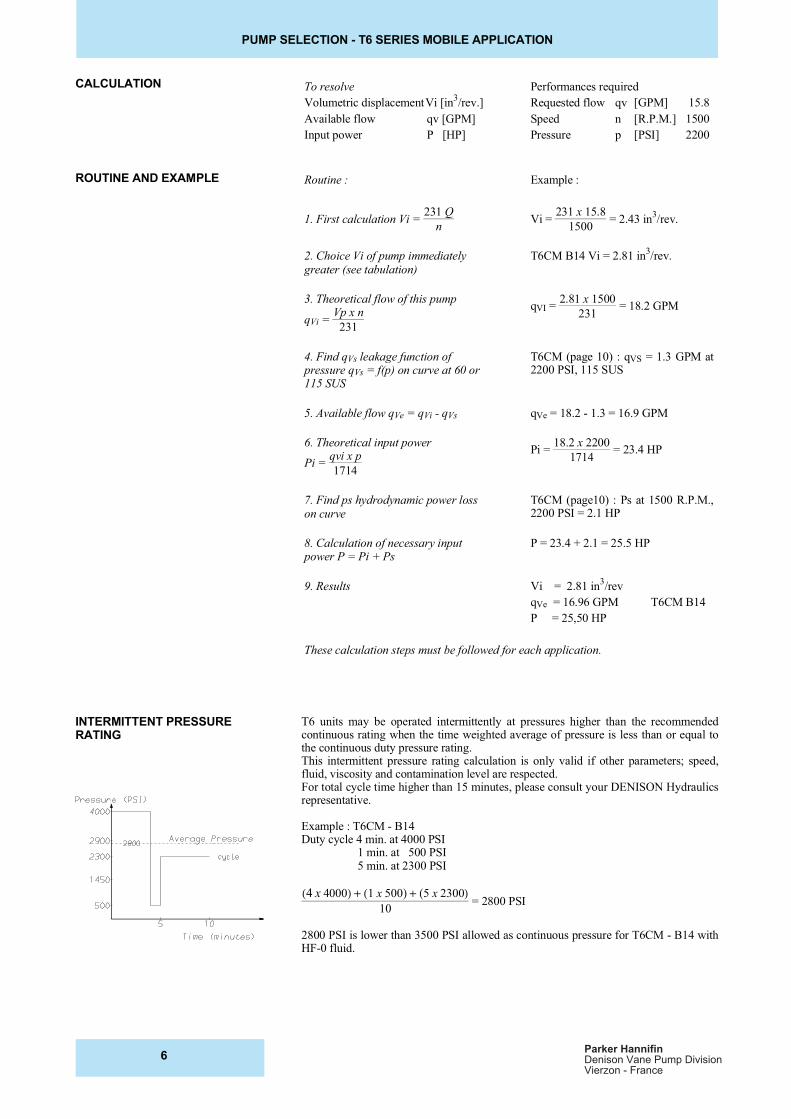
T6 units may be operated intermittently at pressures higher than the recommendedcontinuous rating when the time weighted average of pressure is less than or equal tothe continuous duty pressure rating.This intermittent pressure rating calculation is only valid if other parameters; speed,fluid, viscosity and contamination level are respected.For total cycle time higher than 15 minutes, please consult your DENISON Hydraulicsrepresentative.
Example : T6CM - B14Duty cycle 4 min. at 4000 PSI 1 min. at 500 PSI 5 min. at 2300 PSI
(4 x 4000) + (1 x 500) + (5 x 2300)
10 = 2800 PSI
2800 PSI is lower than 3500 PSI allowed as continuous pressure for T6CM - B14 withHF-0 fluid.
INTERMITTENT PRESSURERATING
CALCULATION
ROUTINE AND EXAMPLE
6Parker Hannifin
Denison Vane Pump DivisionVierzon - France
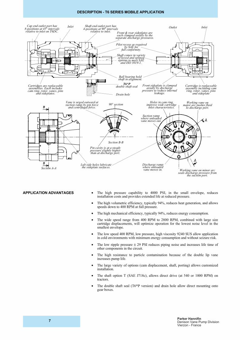
DESCRIPTION - T6 SERIES MOBILE APPLICATION
Cap end outlet port has8-positions at 45° intervalsrelative to inlet on T6DC.
Inlet Shaft end outlet port has4-positions at 90° intervals
relative to inlet. Front & rear sideplates areeach clamped axially by the
separate discharge pressures.
Pilot recess as requiredby SAE for
full conformity.
Shaft comes in varietyof keyed and splinedoptions to meet SAE
and ISO 3019-1.
Ball bearing holdshaft in alignment.
Front sideplate is clampedaxially by discharge
pressure to reduce internalleakage.
Cartridges are replaceableassemblies. Each includes
cam ring, rotor, vanes, pinsand sideplates.
Cartridge is replaceableassembly including camring, rotor, vanes, pins
and sideplate
Outlet Inlet
Vane is urged outward atsuction ramp by pin force
and centrifugal force.90° section
Holes in cam ringimprove wide cartridge
inlet characteristics.
Working vane onmajor arc pushes fluid
to discharge port.
Suction rampwhere unloadedvane moves out.
Section B-B
Section A-A
Pin cavity is at a steadypressure slightly higherthan at discharge port.
Discharge rampwhere unloadedvane moves in.
Lub side holes lubricatethe sideplate surfaces.
Working vane on minor arcseals discharge pressure from
the suction port.
T6*Pdouble shaft seal
Drain hole
• The high pressure capability to 4000 PSI, in the small envelope, reducesinstallation costs and provides extended life at reduced pressure.
• The high volumetric efficiency, typically 94%, reduces heat generation, and allowsspeeds down to 400 RPM at full pressure.
• The high mechanical efficiency, typically 94%, reduces energy consumption.
• The wide speed range from 400 RPM to 2800 RPM, combined with large sizecartridge displacements, will optimize operation for the lowest noise level in thesmallest envelope.
• The low speed 400 RPM, low pressure, high viscosity 9240 SUS allow applicationin cold environments with minimum energy consumption and without seizure risk.
• The low ripple pressure=± 29 PSI reduces piping noise and increases life time ofother components in the circuit.
• The high resistance to particle contamination because of the double lip vaneincreases pump life.
• The large variety of options (cam displacement, shaft, porting) allows customizedinstallation.
• The shaft option T (SAE J718c), allows direct drive (at 540 or 1000 RPM) ontractors.
• The double shaft seal (T6*P version) and drain hole allow direct mounting ontogear boxes.
APPLICATION ADVANTAGES
7Parker Hannifin
Denison Vane Pump DivisionVierzon - France
SHAFTS AND HYDRAULIC FLUIDS - T6 SERIES MOBILE APPLICATION
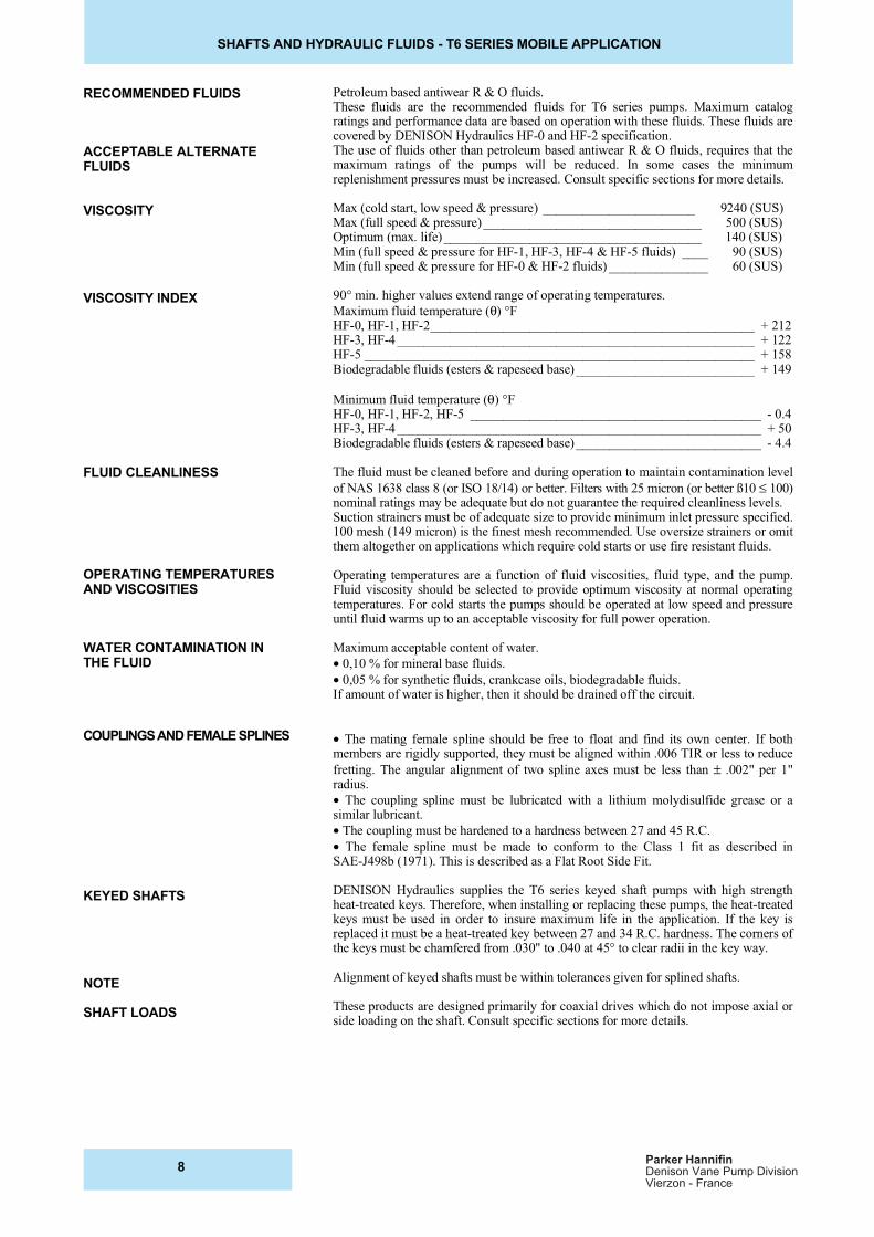
RECOMMENDED FLUIDS
ACCEPTABLE ALTERNATEFLUIDS
VISCOSITY
VISCOSITY INDEX
FLUID CLEANLINESS
OPERATING TEMPERATURESAND VISCOSITIES
WATER CONTAMINATION INTHE FLUID
COUPLINGS AND FEMALE SPLINES
KEYED SHAFTS
NOTE
SHAFT LOADS
Petroleum based antiwear R & O fluids.These fluids are the recommended fluids for T6 series pumps. Maximum catalogratings and performance data are based on operation with these fluids. These fluids arecovered by DENISON Hydraulics HF-0 and HF-2 specification.The use of fluids other than petroleum based antiwear R & O fluids, requires that themaximum ratings of the pumps will be reduced. In some cases the minimumreplenishment pressures must be increased. Consult specific sections for more details.
Max (cold start, low speed & pressure) _______________________ 9240 (SUS)Max (full speed & pressure)_________________________________ 500 (SUS)Optimum (max. life)_______________________________________ 140 (SUS)Min (full speed & pressure for HF-1, HF-3, HF-4 & HF-5 fluids) ____ 90 (SUS)Min (full speed & pressure for HF-0 & HF-2 fluids) _______________ 60 (SUS)
90° min. higher values extend range of operating temperatures.
Maximum fluid temperature (θ) °FHF-0, HF-1, HF-2_________________________________________________ + 212HF-3, HF-4 ______________________________________________________ + 122HF-5 ___________________________________________________________ + 158Biodegradable fluids (esters & rapeseed base)___________________________ + 149
Minimum fluid temperature (θ) °FHF-0, HF-1, HF-2, HF-5 ____________________________________________ - 0.4HF-3, HF-4 _______________________________________________________ + 50Biodegradable fluids (esters & rapeseed base)____________________________ - 4.4
The fluid must be cleaned before and during operation to maintain contamination level
of NAS 1638 class 8 (or ISO 18/14) or better. Filters with 25 micron (or better ß10 ≤ 100)nominal ratings may be adequate but do not guarantee the required cleanliness levels.Suction strainers must be of adequate size to provide minimum inlet pressure specified.100 mesh (149 micron) is the finest mesh recommended. Use oversize strainers or omitthem altogether on applications which require cold starts or use fire resistant fluids.
Operating temperatures are a function of fluid viscosities, fluid type, and the pump.Fluid viscosity should be selected to provide optimum viscosity at normal operatingtemperatures. For cold starts the pumps should be operated at low speed and pressureuntil fluid warms up to an acceptable viscosity for full power operation.
Maximum acceptable content of water.
•=0,10 % for mineral base fluids.
• 0,05 % for synthetic fluids, crankcase oils, biodegradable fluids.If amount of water is higher, then it should be drained off the circuit.
•=The mating female spline should be free to float and find its own center. If bothmembers are rigidly supported, they must be aligned within .006 TIR or less to reduce
fretting. The angular alignment of two spline axes must be less than ± .002" per 1"radius.
•=The coupling spline must be lubricated with a lithium molydisulfide grease or asimilar lubricant.
•=The coupling must be hardened to a hardness between 27 and 45 R.C.
•= The female spline must be made to conform to the Class 1 fit as described inSAE-J498b (1971). This is described as a Flat Root Side Fit.
DENISON Hydraulics supplies the T6 series keyed shaft pumps with high strengthheat-treated keys. Therefore, when installing or replacing these pumps, the heat-treatedkeys must be used in order to insure maximum life in the application. If the key isreplaced it must be a heat-treated key between 27 and 34 R.C. hardness. The corners ofthe keys must be chamfered from .030" to .040 at 45° to clear radii in the key way.
Alignment of keyed shafts must be within tolerances given for splined shafts.
These products are designed primarily for coaxial drives which do not impose axial orside loading on the shaft. Consult specific sections for more details.
8Parker Hannifin
Denison Vane Pump DivisionVierzon - France

NOTES - T6 SERIES MOBILE APPLICATION
9Parker Hannifin
Denison Vane Pump DivisionVierzon - France
ORDERING CODE - T6CM SERIES MOBILE APPLICATION
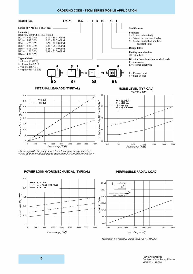
Model No. T6CM - B22 - 1 R 00 - C 1
Series M = Mobile 1 shaft seal
Cam ring(Delivery at 0 PSI & 1200 r.p.m.)B03 = 3.42 GPM B17 = 18.48 GPMB05 = 5.45 GPM B20 = 20.23 GPMB06 = 6.76 GPM B22 = 22.28 GPMB08 = 8.36 GPM B25 = 25.14 GPMB10 = 10.81 GPM B28 = 27.90 GPMB12 = 11.76 GPM B31 = 31.70 GPMB14 = 14.58 GPM
Type of shaft1 = keyed (SAE B)2 = keyed (no SAE)3 = splined (SAE B)4 = splined (SAE BB)
Modification
Seal class1 = S1 (for mineral oil)4 = S4 (for the resistant fluids)5 = S5 (for mineral oil and fire resistant fluids)
Design letter
Porting combination00 = standard
Direct. of rotation (view on shaft end)R = clockwiseL = counter-clockwise
P = Pressure portS = Suction port
INTERNAL LEAKAGE (TYPICAL) NOISE LEVEL (TYPICAL)
POWER LOSS HYDROMECHANICAL (TYPICAL) PERMISSIBLE RADIAL LOAD
Pressure p [PSI]
Pressure p [PSI]
Speed n [RPM]
Pow
er l
oss
Ps
[HP
]
Load F
[L
bs]
Lp.
Noi
se le
vel [
db(A
)] 1
m I
SO 4
412
Inte
rna
l le
aka
ge
Qs
[GP
M]
Maximum permissible axial load Fa = 180 Lbs
Pressure p [PSI]
Do not operate the pump more than 5 seconds at any speed orviscosity if internal leakage is more than 50% of theoretical flow.
T6CM - B22
10Parker Hannifin
Denison Vane Pump DivisionVierzon - France
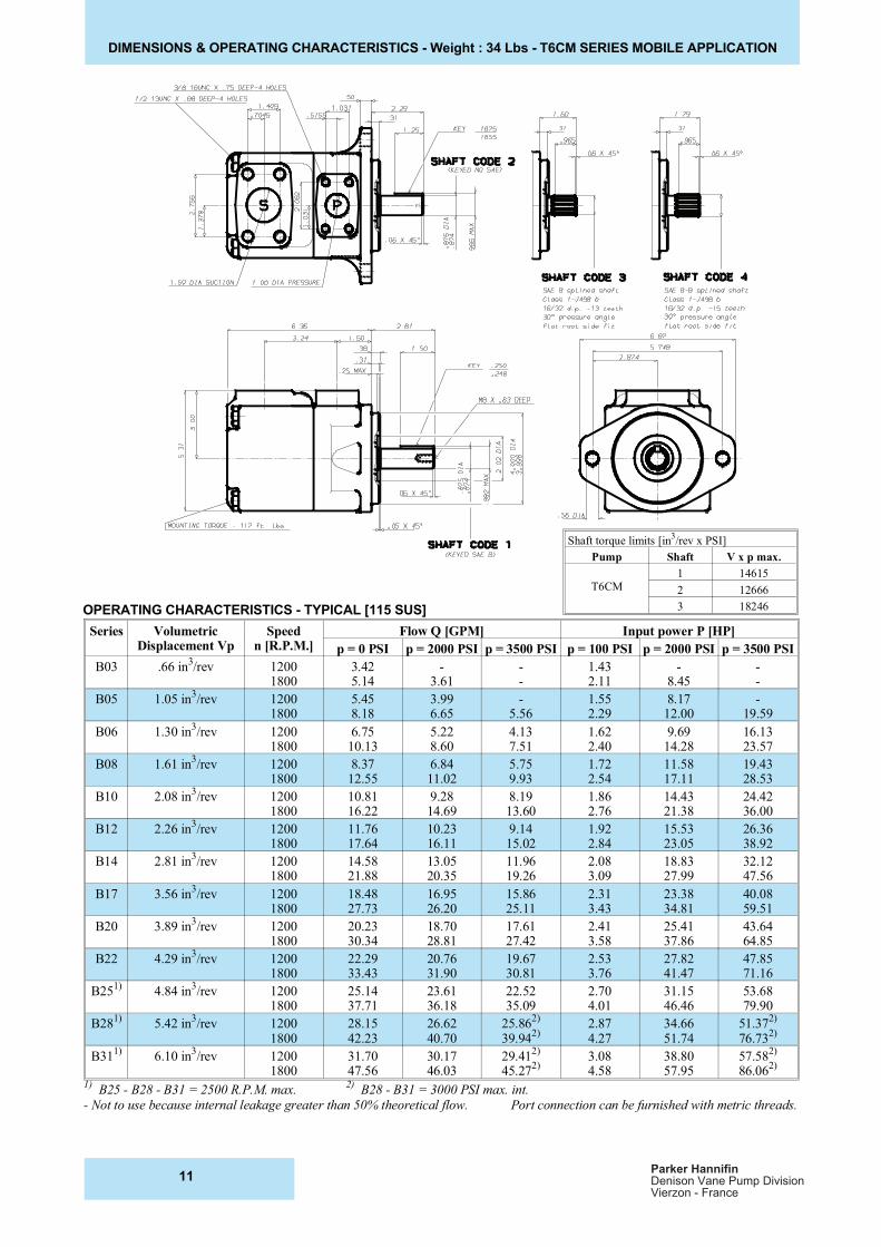
DIMENSIONS & OPERATING CHARACTERISTICS - Weight : 34 Lbs - T6CM SERIES MOBILE APPLICATION
OPERATING CHARACTERISTICS - TYPICAL [115 SUS]
Series VolumetricDisplacement Vp
Speedn [R.P.M.]
Flow Q [GPM] Input power P [HP]
p = 0 PSI p = 2000 PSI p = 3500 PSI p = 100 PSI p = 2000 PSI p = 3500 PSI
B03 .66 in3/rev 1200
18003.425.14
-3.61
--
1.432.11
-8.45
--
B05 1.05 in3/rev 1200
18005.458.18
3.996.65
-5.56
1.552.29
8.1712.00
-19.59
B06 1.30 in3/rev 1200
18006.75
10.135.228.60
4.137.51
1.622.40
9.6914.28
16.1323.57
B08 1.61 in3/rev 1200
18008.37
12.556.8411.02
5.759.93
1.722.54
11.5817.11
19.4328.53
B10 2.08 in3/rev 1200
180010.8116.22
9.2814.69
8.1913.60
1.862.76
14.4321.38
24.4236.00
B12 2.26 in3/rev 1200
180011.7617.64
10.2316.11
9.1415.02
1.922.84
15.5323.05
26.3638.92
B14 2.81 in3/rev 1200
180014.5821.88
13.0520.35
11.9619.26
2.083.09
18.8327.99
32.1247.56
B17 3.56 in3/rev 1200
180018.4827.73
16.9526.20
15.8625.11
2.313.43
23.3834.81
40.0859.51
B20 3.89 in3/rev 1200
180020.2330.34
18.7028.81
17.6127.42
2.413.58
25.4137.86
43.6464.85
B22 4.29 in3/rev 1200
180022.2933.43
20.7631.90
19.6730.81
2.533.76
27.8241.47
47.8571.16
B251)
4.84 in3/rev 1200
180025.1437.71
23.6136.18
22.5235.09
2.704.01
31.1546.46
53.6879.90
B281)
5.42 in3/rev 1200
180028.1542.23
26.6240.70
25.862)
39.942)
2.874.27
34.6651.74
51.372)
76.732)
B311)
6.10 in3/rev 1200
180031.7047.56
30.1746.03
29.412)
45.272)
3.084.58
38.8057.95
57.582)
86.062)
1) B25 - B28 - B31 = 2500 R.P.M. max.
2) B28 - B31 = 3000 PSI max. int.
- Not to use because internal leakage greater than 50% theoretical flow. Port connection can be furnished with metric threads.
Shaft torque limits [in3/rev x PSI]
Pump Shaft V x p max.
T6CM1 14615
2 12666
3 18246
11Parker Hannifin
Denison Vane Pump DivisionVierzon - France
ORDERING CODE - T6CP SERIES MOBILE APPLICATION
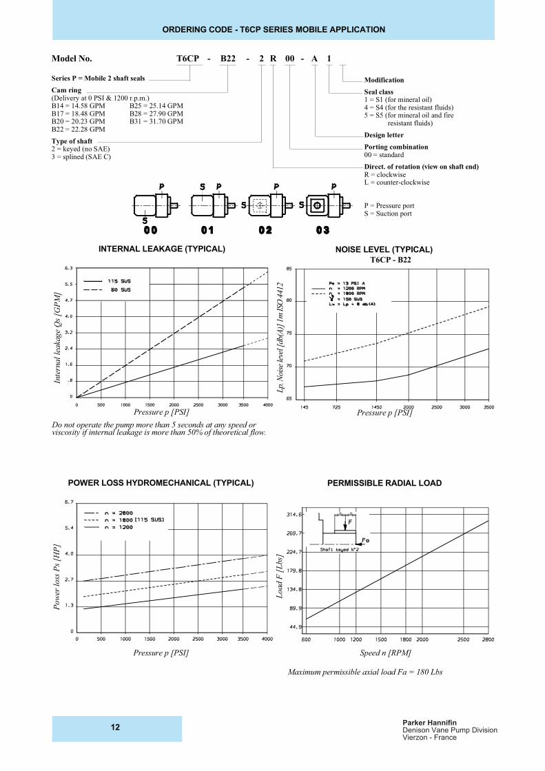
Model No. T6CP - B22 - 2 R 00 - A 1
Series P = Mobile 2 shaft seals
Cam ring(Delivery at 0 PSI & 1200 r.p.m.)B14 = 14.58 GPM B25 = 25.14 GPMB17 = 18.48 GPM B28 = 27.90 GPMB20 = 20.23 GPM B31 = 31.70 GPMB22 = 22.28 GPM
Type of shaft2 = keyed (no SAE)3 = splined (SAE C)
Modification
Seal class1 = S1 (for mineral oil)4 = S4 (for the resistant fluids)5 = S5 (for mineral oil and fire resistant fluids)
Design letter
Porting combination00 = standard
Direct. of rotation (view on shaft end)R = clockwiseL = counter-clockwise
P = Pressure portS = Suction port
INTERNAL LEAKAGE (TYPICAL) NOISE LEVEL (TYPICAL)
POWER LOSS HYDROMECHANICAL (TYPICAL) PERMISSIBLE RADIAL LOAD
Pressure p [PSI]
Lp.
Noi
se le
vel [
db(A
)] 1
m I
SO 4
412
Inte
rna
l le
aka
ge
Qs
[GP
M]
Pressure p [PSI]
Do not operate the pump more than 5 seconds at any speed orviscosity if internal leakage is more than 50% of theoretical flow.
T6CP - B22
Pressure p [PSI] Speed n [RPM]
Pow
er l
oss
Ps
[HP
]
Load F
[L
bs]
Maximum permissible axial load Fa = 180 Lbs
12Parker Hannifin
Denison Vane Pump DivisionVierzon - France
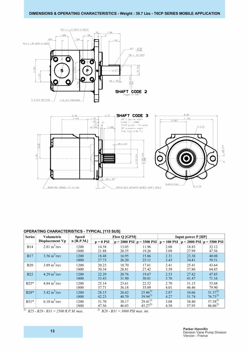
DIMENSIONS & OPERATING CHARACTERISTICS - Weight : 39.7 Lbs - T6CP SERIES MOBILE APPLICATION
OPERATING CHARACTERISTICS - TYPICAL [115 SUS]
Series VolumetricDisplacement Vp
Speedn [R.P.M.]
Flow Q [GPM] Input power P [HP]
p = 0 PSI p = 2000 PSI p = 3500 PSI p = 100 PSI p = 2000 PSI p = 3500 PSI
B14 2.81 in3/rev 1200
180014.5821.88
13.0520.35
11.9619.26
2.083.09
18.8327.99
32.1247.56
B17 3.56 in3/rev 1200
180018.4827.73
16.9526.20
15.8625.11
2.313.43
23.3834.81
40.0859.51
B20 3.89 in3/rev 1200
180020.2330.34
18.7028.81
17.6127.42
2.413.58
25.4137.86
43.6464.85
B22 4.29 in3/rev 1200
180022.2933.43
20.7631.90
19.6730.81
2.533.76
27.8241.47
47.8571.16
B25* 4.84 in3/rev 1200
180025.1437.71
23.6136.18
22.5235.09
2.704.01
31.1546.46
53.6879.90
B28* 5.42 in3/rev 1200
180028.1542.23
26.6240.70
25.862)
39.942)
2.874.27
34.6651.74
51.372)
76.732)
B31* 6.10 in3/rev 1200
180031.7047.56
30.1746.03
29.412)
45.272)
3.084.58
38.8057.95
57.582)
86.062)
1) B25 - B28 - B31 = 2500 R.P.M. max.
2) B28 - B31 = 3000 PSI max. int.
13Parker Hannifin
Denison Vane Pump DivisionVierzon - France
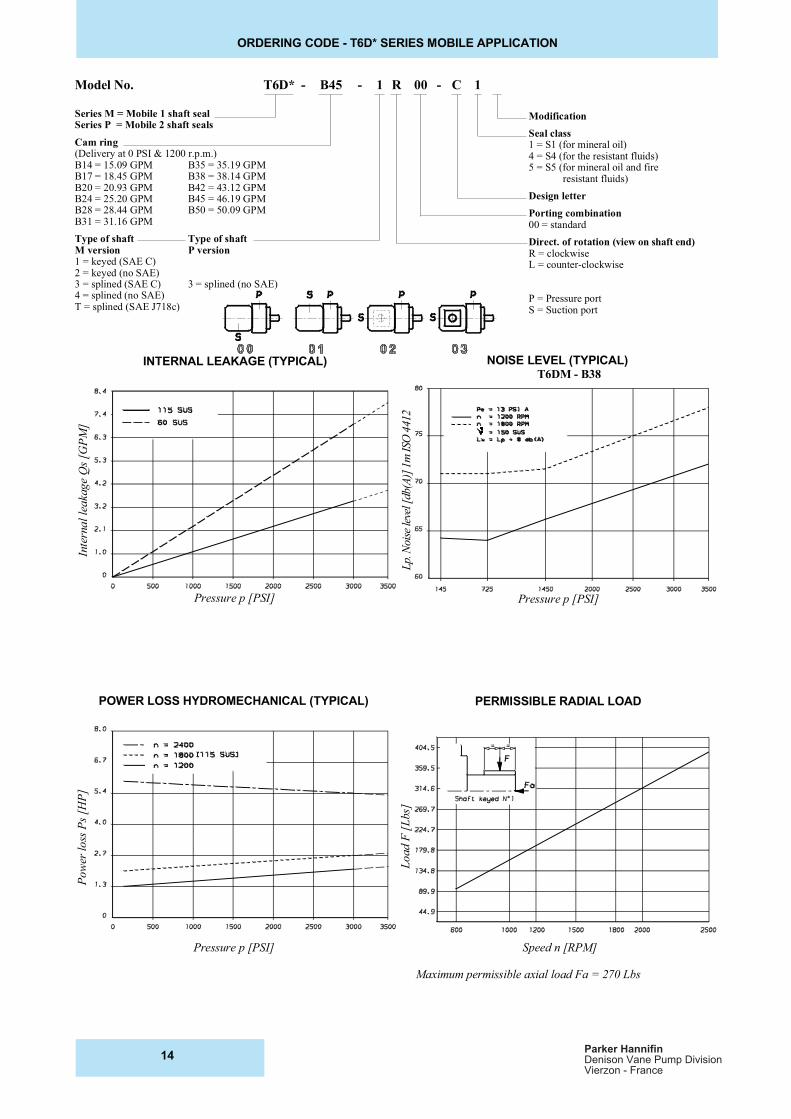
Model No. T6D* - B45 - 1 R 00 - C 1
Series M = Mobile 1 shaft sealSeries P = Mobile 2 shaft seals
Cam ring(Delivery at 0 PSI & 1200 r.p.m.)B14 = 15.09 GPM B35 = 35.19 GPMB17 = 18.45 GPM B38 = 38.14 GPMB20 = 20.93 GPM B42 = 43.12 GPMB24 = 25.20 GPM B45 = 46.19 GPMB28 = 28.44 GPM B50 = 50.09 GPMB31 = 31.16 GPM
Type of shaft Type of shaftM version P version1 = keyed (SAE C)2 = keyed (no SAE)3 = splined (SAE C) 3 = splined (no SAE)4 = splined (no SAE)T = splined (SAE J718c)
Modification
Seal class1 = S1 (for mineral oil)4 = S4 (for the resistant fluids)5 = S5 (for mineral oil and fire resistant fluids)
Design letter
Porting combination00 = standard
Direct. of rotation (view on shaft end)R = clockwiseL = counter-clockwise
P = Pressure portS = Suction port
ORDERING CODE - T6D* SERIES MOBILE APPLICATION
Pow
er l
oss
Ps
[HP
]
Load F
[L
bs]
Maximum permissible axial load Fa = 270 Lbs
Lp.
Noi
se le
vel [
db(A
)] 1
m I
SO 4
412
Inte
rna
l le
aka
ge
Qs
[GP
M]
INTERNAL LEAKAGE (TYPICAL) NOISE LEVEL (TYPICAL)
POWER LOSS HYDROMECHANICAL (TYPICAL) PERMISSIBLE RADIAL LOAD
Pressure p [PSI]
Pressure p [PSI]
Speed n [RPM]
Pressure p [PSI]
T6DM - B38
14Parker Hannifin
Denison Vane Pump DivisionVierzon - France
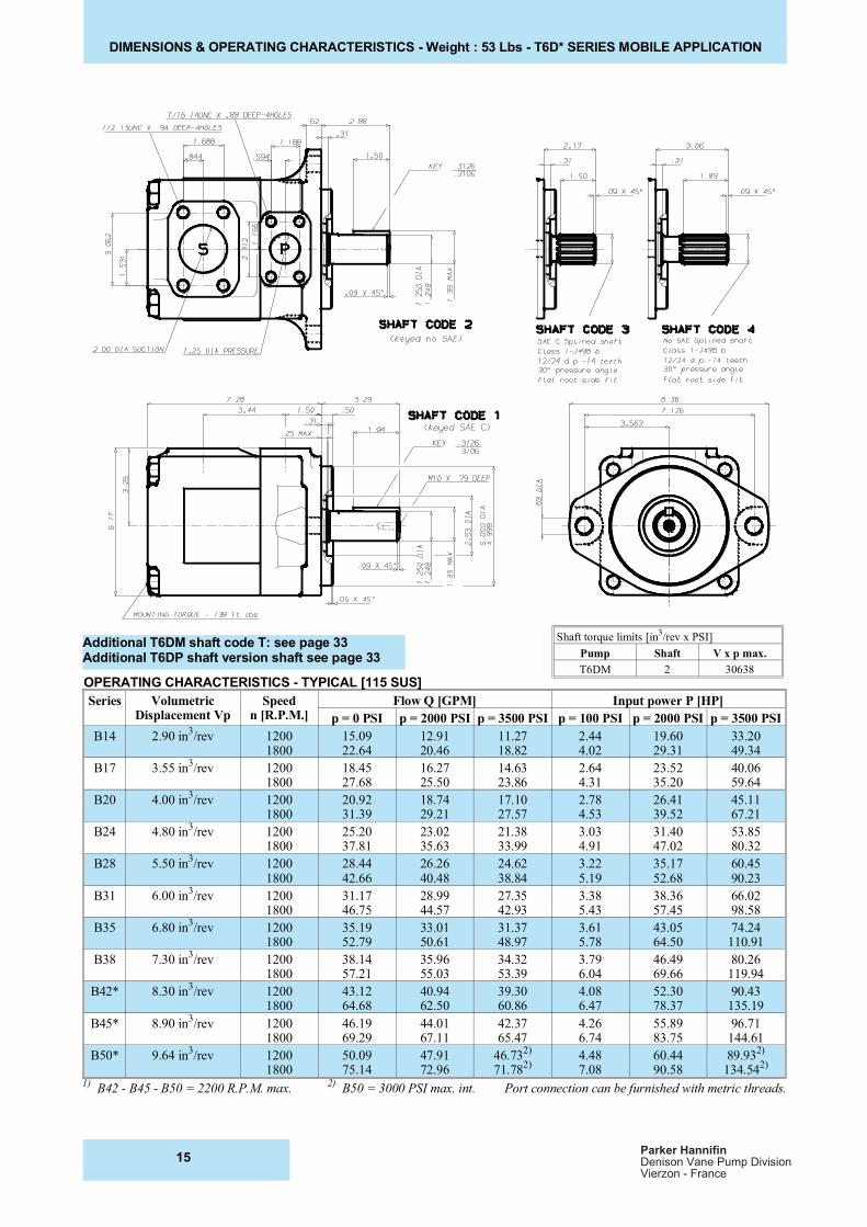
DIMENSIONS & OPERATING CHARACTERISTICS - Weight : 53 Lbs - T6D* SERIES MOBILE APPLICATION
Additional T6DM shaft code T: see page 33Additional T6DP shaft version shaft see page 33
Series VolumetricDisplacement Vp
Speedn [R.P.M.]
Flow Q [GPM] Input power P [HP]
p = 0 PSI p = 2000 PSI p = 3500 PSI p = 100 PSI p = 2000 PSI p = 3500 PSI
B14 2.90 in3/rev 1200
180015.0922.64
12.9120.46
11.2718.82
2.444.02
19.6029.31
33.2049.34
B17 3.55 in3/rev 1200
180018.4527.68
16.2725.50
14.6323.86
2.644.31
23.5235.20
40.0659.64
B20 4.00 in3/rev 1200
180020.9231.39
18.7429.21
17.1027.57
2.784.53
26.4139.52
45.1167.21
B24 4.80 in3/rev 1200
180025.2037.81
23.0235.63
21.3833.99
3.034.91
31.4047.02
53.8580.32
B28 5.50 in3/rev 1200
180028.4442.66
26.2640.48
24.6238.84
3.225.19
35.1752.68
60.4590.23
B31 6.00 in3/rev 1200
180031.1746.75
28.9944.57
27.3542.93
3.385.43
38.3657.45
66.0298.58
B35 6.80 in3/rev 1200
180035.1952.79
33.0150.61
31.3748.97
3.615.78
43.0564.50
74.24110.91
B38 7.30 in3/rev 1200
180038.1457.21
35.9655.03
34.3253.39
3.796.04
46.4969.66
80.26119.94
B42* 8.30 in3/rev 1200
180043.1264.68
40.9462.50
39.3060.86
4.086.47
52.3078.37
90.43135.19
B45* 8.90 in3/rev 1200
180046.1969.29
44.0167.11
42.3765.47
4.266.74
55.8983.75
96.71144.61
B50* 9.64 in3/rev 1200
180050.0975.14
47.9172.96
46.732)
71.782)
4.487.08
60.4490.58
89.932)
134.542)
1) B42 - B45 - B50 = 2200 R.P.M. max.
2) B50 = 3000 PSI max. int. Port connection can be furnished with metric threads.
OPERATING CHARACTERISTICS - TYPICAL [115 SUS]
Shaft torque limits [in3/rev x PSI]
Pump Shaft V x p max.
T6DM 2 30638
15Parker Hannifin
Denison Vane Pump DivisionVierzon - France
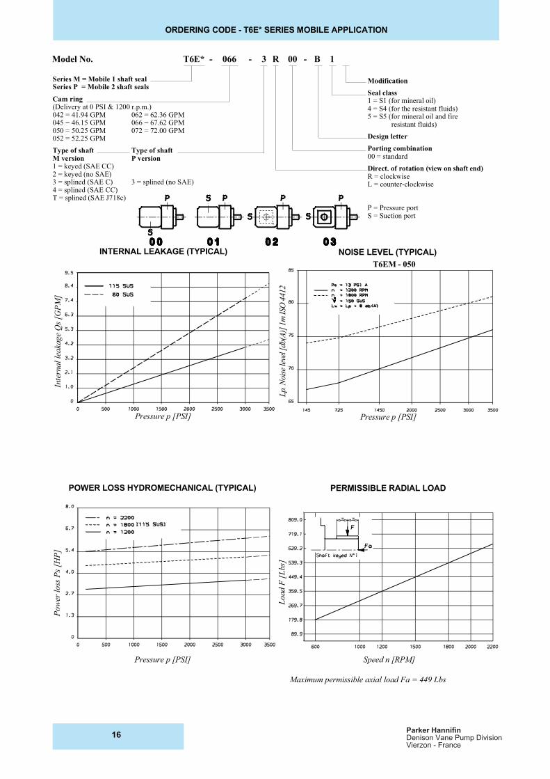
Model No. T6E* - 066 - 3 R 00 - B 1
Series M = Mobile 1 shaft sealSeries P = Mobile 2 shaft seals
Cam ring(Delivery at 0 PSI & 1200 r.p.m.)042 = 41.94 GPM 062 = 62.36 GPM045 = 46.15 GPM 066 = 67.62 GPM050 = 50.25 GPM 072 = 72.00 GPM052 = 52.25 GPM
Type of shaft Type of shaftM version P version1 = keyed (SAE CC)2 = keyed (no SAE)3 = splined (SAE C) 3 = splined (no SAE)4 = splined (SAE CC)T = splined (SAE J718c)
Modification
Seal class1 = S1 (for mineral oil)4 = S4 (for the resistant fluids)5 = S5 (for mineral oil and fire resistant fluids)
Design letter
Porting combination00 = standard
Direct. of rotation (view on shaft end)R = clockwiseL = counter-clockwise
P = Pressure portS = Suction port
ORDERING CODE - T6E* SERIES MOBILE APPLICATION
Lp.
Noi
se le
vel [
db(A
)] 1
m I
SO 4
412
Inte
rna
l le
aka
ge
Qs
[GP
M]
Pow
er l
oss
Ps
[HP
]
Load F
[L
bs]
Maximum permissible axial load Fa = 449 Lbs
INTERNAL LEAKAGE (TYPICAL) NOISE LEVEL (TYPICAL)
POWER LOSS HYDROMECHANICAL (TYPICAL) PERMISSIBLE RADIAL LOAD
Pressure p [PSI]
Pressure p [PSI]
Speed n [RPM]
Pressure p [PSI]
T6EM - 050
16Parker Hannifin
Denison Vane Pump DivisionVierzon - France
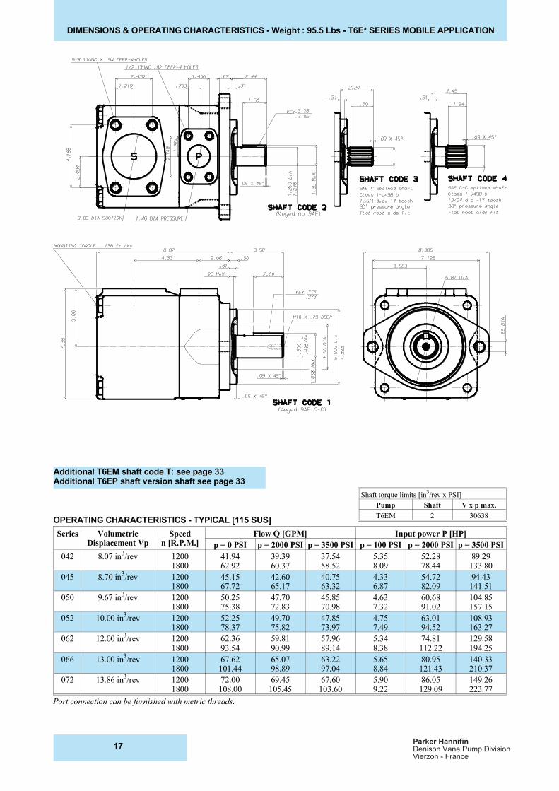
DIMENSIONS & OPERATING CHARACTERISTICS - Weight : 95.5 Lbs - T6E* SERIES MOBILE APPLICATION
Additional T6EM shaft code T: see page 33Additional T6EP shaft version shaft see page 33
OPERATING CHARACTERISTICS - TYPICAL [115 SUS]
Series VolumetricDisplacement Vp
Speedn [R.P.M.]
Flow Q [GPM] Input power P [HP]
p = 0 PSI p = 2000 PSI p = 3500 PSI p = 100 PSI p = 2000 PSI p = 3500 PSI
042 8.07 in3/rev 1200
180041.9462.92
39.3960.37
37.5458.52
5.358.09
52.2878.44
89.29133.80
045 8.70 in3/rev 1200
180045.1567.72
42.6065.17
40.7563.32
4.336.87
54.7282.09
94.43141.51
050 9.67 in3/rev 1200
180050.2575.38
47.7072.83
45.8570.98
4.637.32
60.6891.02
104.85157.15
052 10.00 in3/rev 1200
180052.2578.37
49.7075.82
47.8573.97
4.757.49
63.0194.52
108.93163.27
062 12.00 in3/rev 1200
180062.3693.54
59.8190.99
57.9689.14
5.348.38
74.81112.22
129.58194.25
066 13.00 in3/rev 1200
180067.62101.44
65.0798.89
63.2297.04
5.658.84
80.95121.43
140.33210.37
072 13.86 in3/rev 1200
180072.00108.00
69.45105.45
67.60103.60
5.909.22
86.05129.09
149.26223.77
Port connection can be furnished with metric threads.
Shaft torque limits [in3/rev x PSI]
Pump Shaft V x p max.
T6EM 2 30638
17Parker Hannifin
Denison Vane Pump DivisionVierzon - France