Embed Size (px)
Citation preview

-1- WK 144 619
WK144 619
04.1999r.
VANE PUMP TYPE V3/63
Vane pumps type PV serve to generate an oil flow in hy-draulic systems.
ADVANTAGES
- easy commissioning by automatic air bleeding- low noise level- hydrodynamically lubricated bearings for long bearing life- good sliding characteristics of control discs due to bronze coating and semi-fluid friction.
DESCRIPTION OF OPERATION
Hydraulic pumps type V3 are vane pumps with variable dis-placement and pressure control. Pumps type V3/63 are com-posed of a housing 1, rotor 2 with simple vanes 3, stator 4,pressure regulator 5, volume screw 6, valve for automatic airbleed 7 and control discs 9.
Size 63 up to 10MPa 63 dm3/min

- 2 -WK 144 619
Mineral oil, phosphate ester
Working temperature ( fluid in a tank ) K 313 - 328
Pipe connections threaded connections
Fluid temperature range K 263 - 343
Filtration µm 16 ( recommended 10 for long working life )
Hydraulic fluid
Nominal output flow
Nominal viscosity range - at p
zero stroke < 6.3 MPa mm2/s 16 to 160
- at pzero stroke
> 6.3 MPa mm2/s 25 to 160
Rotation direction right ( or left for 1 PV6 only )
Leakage pressure MPa max 0.2
p = 1 MPa dm3/min 67 at n = 1450 min -1
Inlet pressure MPa - 0.02 to + 0.5
Outlet pressure MPa max 10
Torque ( drive shaft ) Nm max 353
Revolution per minute min -1 1000 to 1 800
Weight kg 29.5 ( 1 PV2), 30.5 ( 1 PV6)
Shaft loading radial or axial loads can not be transferred
Mounting method flange or subplate mounting
Pressure range related to spring force MPa C 25 from 1.2 to 2.5 C 40 from 2.0 to 4.0 C 63 from 3.0 to 6.3 C 100 from 5.0 to 10.0
Suction and delivery
Two vanes 3, the rotor 2, the stator 4 and the discs 9 formthe chambers for the transport of the fluid. By moving therotor 2 to the right the chambers 8 increase, starting fromthe suction channel and they fill up with fluid. When thesechambers have reached their maximum volume they areseparated from the suction side by means of the controldiscs. When the rotor further turns to the right the cham-bers are connected to the pressure side. They decreasetheir volume and thus fluid is pushed to the pressure chan-nel P and into the system. Volume setting screw 6 is de-signed for limiting the maximum flow of the pump.
Drive
The pump may be connected to motor only by means of aflexible coupling. All the coaxial conditions formulated bythe coupling manufacturer must be maintained.The shaft ends of both pump and motor may not transmitany longitudinal or radial forces.
Oil tank
The tank capacity must be properly selected so that theworking temperature of oil do not exceed recommenda-tions. If that is impossible a cooler must be installed.
Pressure setting
The circular stator ring is kept in an eccentric position bymeans of the spring 10. Maximum working pressure re-quired in the system is adjusted by the spring 10. On reach-ing the set pressure the stator 4 ( overcoming resistance ofthe spring 10 ) moves out of its eccentric position. Theeccentricity decreases till the minimum flow replacing theleakage oil is obtained. After a pressure drop in the systamthe stator 4 returns to the eccentric position and the pumpdelivers the full value of the set output flow.
Pipelines
The suction line should be designed so that the givesvalues of inlet pressure are not exceeded. The leakagelines should be fitted minimum 100 mm above the suctionline and should be formed so that the leakages do not getimmediately sucked back into the pump.The suction lines and the leakage lines should be at least200 mm apart. The pipe ends should be cut at a 45O angleand should not reach within 50 mm of the tank bottom.
All pipelines even at the minimum oil level in the tankmust be dipped minimum 50 mm in order to avoid thebuild-up of foam.
Installation
Vane pumps type V3 can be installed in any desiredposition. The pump may be connected to hydraulicsystems only by means of flexible lines.
TECHNICAL DATA

-3- WK 144 619
Pump for subplate mounting -overall dimensions in mm
OVERALL AND MOUNTING DIMENSIONS
Admissible surfaceroughness and flatnessdeviation for a subplateface.
9. Accessories (against special order and agreed with the manufacturer). Setting by means of hand wheel fitted on square end setting10. Flow rate setting by means of external square end ( H )11. Pressure setting by means of external square end ( H )12. Flow rate setting locked by key ( S )13. Pressure setting locked by key ( S )14. Key length 43 mm15. Interface16. Drive shaft for model with left rotation17. 2-nd shaft end for model 1PV...V3...D18. O-ring 44.1 × 2.619. O-ring 15.6 × 2.620. O-ring 34.6 × 2.6
1. Flow rate setting - rotation to the right decreases flow rate - rotation to the left increases flow rate2. Pressure setting - rotation to the right increases operating pressure - rotation to the left decreases operating pressure3. Flow rate setting ( by means of screw A )4. Pressure setting ( by means of screw C )5. Pressure port6. Leakage port7. Suction port8. Drive shaft for model with right rotation

- 4 -WK 144 619
8. Drive shaft for model with right rotation9. Accessories (against special order and agreed with the manufacturer). Setting by means of hand wheel fitted on square end setting10. Flow rate setting by means of external square end ( H )11. Pressure setting by means of external square end ( H )12. Flow rate setting locked by key ( S )13. Pressure setting locked by key ( S )14. Key length 43 mm15. 2-nd shaft end
1. Flow rate setting - rotation to the right decreases flow rate - rotation to the left increases flow rate2. Pressure setting - rotation to the right increases operating pressure - rotation to the left decreases operating pressure3. Flow rate setting ( by means of screw A )4. Pressure setting ( by means of screw C )5. Pressure port6. Leakage port7. Suction port
OVERALL AND MOUNTING DIMENSIONSPump for flange mounting - overall dimensions in mm
-5- WK 144 619
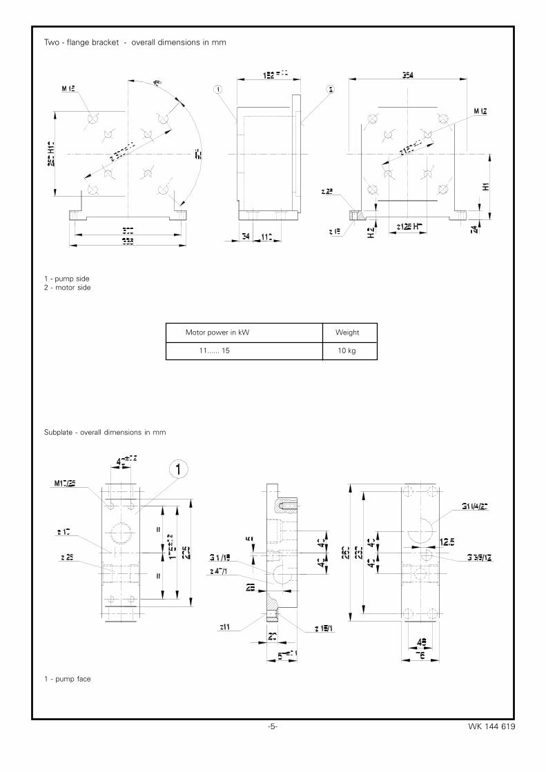
Motor power in kW Weight
11...... 15 10 kg
Two - flange bracket - overall dimensions in mm
1 - pump side2 - motor side
Subplate - overall dimensions in mm
1 - pump face

- 6 -WK 144 619
5.5.....7.5 15 132 207
11......15 43 160 235
Drive power in kW H1 H2±0.2 H3
18.5......22 63 180 255
1 - pump side
Overall dimensions for single-flange bracket related to motor size
Single-flange bracket - overall dimensions in mm
-7- WK 144 619
0,5 1 1,5 2 2,5
p (MPa)
50
60
70
5
6
7
440
3
2
1
30
20
10
0
Q (dm
/ m
in)
P (kW
)
C25
roboczy
ja³owy
50
60
70
10
12
14
840
6
4
2
30
20
10
0
Q (dm
/ m
in)
P (kW
)
21 43p (MPa)
C40
roboczy
ja³owy
50
60
70
10
12
14
840
6
4
2
30
20
10
0
Q (dm
/ m
in)
P (kW
)
2 106 84p (MPa)
C100
roboczy
ja³owy
50
60
70
10
12
14
840
6
4
2
30
20
10
0
Q (dm
/ m
in)
P (kW
)
21 65 743p (MPa)
C63
roboczy
ja³owy
20 4 6 8 10p (MPa)
70
60
65
55
(dB
)
1
2
2
3
6
5
4
1
0 2 4 6 8 10
p (MPa)
L (dm
/ m
in)
A
33 3
33
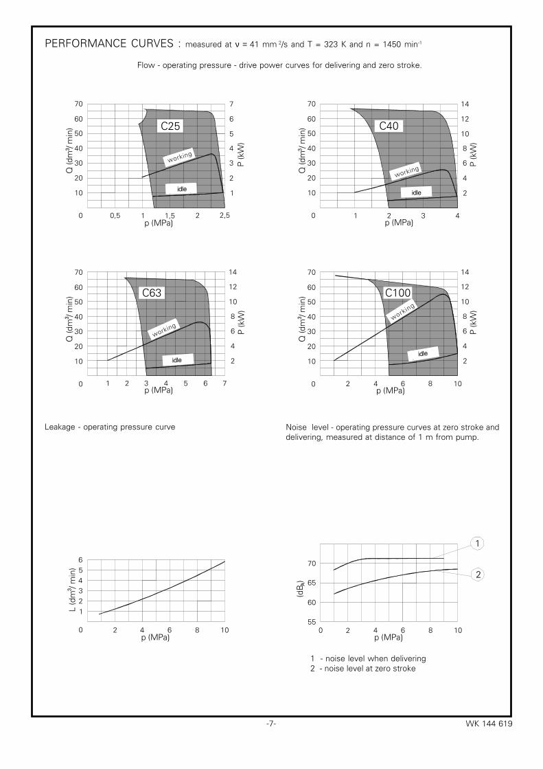
PERFORMANCE CURVES : measured at ν = 41 mm 2/s and T = 323 K and n = 1450 min-1
Flow - operating pressure - drive power curves for delivering and zero stroke.
Leakage - operating pressure curve
1 - noise level when delivering2 - noise level at zero stroke
Noise level - operating pressure curves at zero stroke anddelivering, measured at distance of 1 m from pump.
working
idle
working
idle
working
idle
working
idle

Q-HYDRAULIKA, RakovníkRabasova 2281, 269 01 Rakovník, tel./fax: 313 514 718
e-mail: [email protected], www.q-hydraulika.cz
��� ���������
�� �� � ������
������� �������������������������������������������������������� �� ���� �� �������������������������������������� ���������
���� ����� ������������������������������� !���������������������
�� � ���� ����� ���� �"��������������������������������������������������������������������"#�$�������������������������������������������������������������������#%�����&������� ������$������������������������������'
������ ����� ���(�)��������������������������������������������������� !�������������������������������������������������������������
���������)�$�������������)������� �����������������������������������������������������%��)�$���������!���!���������)� �������������������������������������������*
��������� �� ����������+�����������)�&�������������������������������������������������������������,������-��)��������)�&����������������������������������������������������������������.#��/� ���!)����)��)�������)���������������������������������������������������������
����� � ����� ��������� ��������%0��1�)����)�/��!)����)�����������������������������������������������������������23�%0��1�)����)�/��!)����)�������������������������������������������������������3�2��%0��1�)����)�/��!)����)��������������������������������������������������������24�%0��1�)����)�/��!)����)������������������������������������������������������4
���� ������ �5)��)���������������&�6����&��� ���&�������� ��$�)&�)���������������$����)�)2
!��"� �� ����������+�����������)�&�������������������������������������������������������������7������-��)��������)�&����������������������������������������������������������������.#��/� ���$��&�)�������)�����������������������������������������������������������������
7�)� �����8��8�
7����������)�-��)��������������)���+�� ���� ����)����&������������$����)�)��
,�������+��!���9���0**3��:�3�"�%,���7�