Embed Size (px)
Citation preview
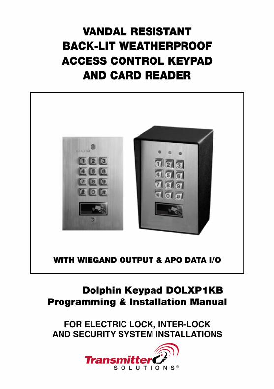
VANDAL RESISTANTBACK-LIT WEATHERPROOFACCESS CONTROL KEY
AND CARD READERPAD
WITH WIEGAND OUTPUT & APO DATA I/O
Dolphin Keypad DOLXP1KBProgramming & Installation Manual
FOR ELECTRIC LOCK, INTER-LOCKAND SECURITY SYSTEM INSTALLATIONS

TABLE OF CONTENTS
INTRODUCTION
FEATURES
SPECIFICATIONS
INSTALLATION
Precautions
Package Contents
CONNECTION TERMINALS
The On-Board LED Indicators
The Pacifier Tones & The LED Signals
The Jumper for Back-Lit Selection
FEATURE PROGRAMMING & OPERATION INSTRUCTIONS
Set System in Programming Mode with The Master Code
Direct Access to Programming Mode with The “DAP” Code – 8 0 8 0
Refresh The System with The “Refreshing Code” --- 9 9 9 9
The Default Values of The Keypad
KEYPAD PROGRAMMING MAKE SIMPLE – For General Users
FEATURE PROGRAMMING -- KEY IN AND STORE THE DESIRED VALUES
Programming Criteria for Codes
Record A Master Code
Record A Super User PIN
Operation And Functions of The Super User PIN
Record-Delete PINs for Output 1, 2, & 3
Examples – Programming And Operation
Visitor Codes (For Output 1 Only)
Duress Codes (For Outputs 1, 2 & 3)
The Operation And Function of The Duress Code
Configuration of The Output Modes for Output 1, 2 And 3
Personal Safety And System Lock-Out
User PIN Entry Mode
Pacifier Tones On-Off Selection
Output Operation Announcer
Status LED Flashing On-Off during Standby
Door Forced Open Warning & Timing
Door Propped-Up Warning & The Delay Time
Intelligent Egress Button – An Unique Feature of A Contemporary Keypad
Where And Why “Going Out” Needs Attention
Egress Delay , Warning And Alarm
Configurations of The Egress Warning And Alarm
Door Opening Alarm & Timer
. . . . . . . . . . . . . . . . . . . . . . . . . . . . . . . . . . . . . . . . . . . . . . . . . . . . . . . . . . . . . . . . . . . . . . . . . . . . . . . . . . . . . . . . . . 4
. . . . . . . . . . . . . . . . . . . . . . . . . . . . . . . . . . . . . . . . . . . . . . . . . . . . . . . . . . . . . . . . . . . . . . . . . . . . . . . . . . . . . . . . . . . . . . . 4
. . . . . . . . . . . . . . . . . . . . . . . . . . . . . . . . . . . . . . . . . . . . . . . . . . . . . . . . . . . . . . . . . . . . . . . . . . . . . . . . . . . . . . . . . . 5
. . . . . . . . . . . . . . . . . . . . . . . . . . . . . . . . . . . . . . . . . . . . . . . . . . . . . . . . . . . . . . . . . . . . . . . . . . . . . . . . . . . . . . . . . . . . 6
. . . . . . . . . . . . . . . . . . . . . . . . . . . . . . . . . . . . . . . . . . . . . . . . . . . . . . . . . . . . . . . . . . . . . . . . . . . . . . . . . . . . . . . . . . . . 6
. . . . . . . . . . . . . . . . . . . . . . . . . . . . . . . . . . . . . . . . . . . . . . . . . . . . . . . . . . . . . . . . . . . . . . . . . . . . . . . . . . . . . . . . . 6
. . . . . . . . . . . . . . . . . . . . . . . . . . . . . . . . . . . . . . . . . . . . . . . . . . . . . . . . . . . . . . . . . . . . . . . . . . . . . . . . . 7
. . . . . . . . . . . . . . . . . . . . . . . . . . . . . . . . . . . . . . . . . . . . . . . . . . . . . . . . . . . . . . . . . . . . . . . . . . . . . 9
. . . . . . . . . . . . . . . . . . . . . . . . . . . . . . . . . . . . . . . . . . . . . . . . . . . . . . . . . . . . . . . . . . . . . . 9
. . . . . . . . . . . . . . . . . . . . . . . . . . . . . . . . . . . . . . . . . . . . . . . . . . . . . . . . . . . . . . . . . . . . . . . . . 9
. . . . . . . . . . . . . . . . . . . . . . . . . . . . . . . . . . . . . . . . . . . . . . . . . . . . . 1 0
. . . . . . . . . . . . . . . . . . . . . . . . . . . . . . . . . . . . . . . . . . . . . . . . . . . . 1 0
. . . . . . . . . . . . . . . . . . . . . . . . . . . . . . . . . . . . . . . . . . 1 0
. . . . . . . . . . . . . . . . . . . . . . . . . . . . . . . . . . . . . . . . . . . . . . . . . . 1 1
. . . . . . . . . . . . . . . . . . . . . . . . . . . . . . . . . . . . . . . . . . . . . . . . . . . . . . . . . . . . . . . . . . . . . . . . 1 1
. . . . . . . . . . . . . . . . . . . . . . . . . . . . . . . . . . . . . . . . . . . . . . . . . 1 2
. . . . . . . . . . . . . . . . . . . . . . . . . . . . . . . . . . . . . . . . 1 3
. . . . . . . . . . . . . . . . . . . . . . . . . . . . . . . . . . . . . . . . . . . . . . . . . . . . . . . . . . . . . . . . . . . . . . . . . 1 3
. . . . . . . . . . . . . . . . . . . . . . . . . . . . . . . . . . . . . . . . . . . . . . . . . . . . . . . . . . . . . . . . . . . . . . . . . . . . . . . . . 1 4
. . . . . . . . . . . . . . . . . . . . . . . . . . . . . . . . . . . . . . . . . . . . . . . . . . . . . . . . . . . . . . . . . . . . . . . . . . . . . . . 1 4
. . . . . . . . . . . . . . . . . . . . . . . . . . . . . . . . . . . . . . . . . . . . . . . . . . . . . . . . . . 1 4
. . . . . . . . . . . . . . . . . . . . . . . . . . . . . . . . . . . . . . . . . . . . . . . . . . . . . . . . . . . . . . . . . . . 1 5
. . . . . . . . . . . . . . . . . . . . . . . . . . . . . . . . . . . . . . . . . . . . . . . . . . . . . . . . . . . . . . . 1 6
. . . . . . . . . . . . . . . . . . . . . . . . . . . . . . . . . . . . . . . . . . . . . . . . . . . . . . . . . . . . . . . . . . . . . . . . 1 7
. . . . . . . . . . . . . . . . . . . . . . . . . . . . . . . . . . . . . . . . . . . . . . . . . . . . . . . . . . . . . . . . . . . . . 1 8
. . . . . . . . . . . . . . . . . . . . . . . . . . . . . . . . . . . . . . . . . . . . . . . . . . . . . . . . . 1 9
. . . . . . . . . . . . . . . . . . . . . . . . . . . . . . . . . . . . . . . . . . . . . . . . . . . . 2 0
. . . . . . . . . . . . . . . . . . . . . . . . . . . . . . . . . . . . . . . . . . . . . . . . . . . . . . . . . . . . . . . . . . . . 2 0
. . . . . . . . . . . . . . . . . . . . . . . . . . . . . . . . . . . . . . . . . . . . . . . . . . . . . . . . . . . . . . . . . . . . . . . . . . . . . . . . . . 2 1
. . . . . . . . . . . . . . . . . . . . . . . . . . . . . . . . . . . . . . . . . . . . . . . . . . . . . . . . . . . . . . . . . . . . . . . . . . 2 1
. . . . . . . . . . . . . . . . . . . . . . . . . . . . . . . . . . . . . . . . . . . . . . . . . . . . . . . . . . . . . . . . . . . . . . . . . . . . 2 1
. . . . . . . . . . . . . . . . . . . . . . . . . . . . . . . . . . . . . . . . . . . . . . . . . . . . . . . . . . . . . . . . 2 2
. . . . . . . . . . . . . . . . . . . . . . . . . . . . . . . . . . . . . . . . . . . . . . . . . . . . . . . . . . . . . . . . . . . . . 2 2
. . . . . . . . . . . . . . . . . . . . . . . . . . . . . . . . . . . . . . . . . . . . . . . . . . . . . . . . . . . . . . 2 2
. . . . . . . . . . . . . . . . . . . . . . . . . . . . . . . . . . . . . . . 2 3
. . . . . . . . . . . . . . . . . . . . . . . . . . . . . . . . . . . . . . . . . . . . . . . . . . . . . . . . . . . 2 3
. . . . . . . . . . . . . . . . . . . . . . . . . . . . . . . . . . . . . . . . . . . . . . . . . . . . . . . . . . . . . . . . . . . . . . . 2 4
. . . . . . . . . . . . . . . . . . . . . . . . . . . . . . . . . . . . . . . . . . . . . . . . . . . . . . . . 2 4
. . . . . . . . . . . . . . . . . . . . . . . . . . . . . . . . . . . . . . . . . . . . . . . . . . . . . . . . . . . . . . . . . . . . . . . . . . . . . 2 5
2
Close The Programming Mode
THE WIRE HARNESS FOR “WIEGAND DATA OUTPUT” & “Transmitter Solutions DATA I/O”
Split-decoded Keypad System
The Wire Harness
The Operation Modes and The Wiegand Output
Wiegand Output at Keypad Operation Mode
TIMING & ELECTRICAL MANNER OF THE WIEGAND DATA OUTPUT
Diagram of The Wiegand Protocol Timing and Its Electrical Manner
THE 34 BIT WIEGAND DATA OUTPUT READING FROM THE USER PINS
Example: Wiegand Output from PIN / Code Entry
THE Transmitter Solutions DATA I/O PORT -- FOR SETTING UP A SPLIT-DECODED KEYPAD
The Optional Controller --- Introduction
PROGRAMMING SUMMARY CHART
APPLICATION EXAMPLES
Basic Wirings of A Stand Alone Door Lock
Basic Wirings of A Stand Alone Door Lock with Inhibit Authorization Code
Basic Wirings of An Inter-Lock System Using Two Keypads
APPLICATION HINTS FOR THE AUXILIARY TERMINALS
APPENDIX
. . . . . . . . . . . . . . . . . . . . . . . . . . . . . . . . . . . . . . . . . . . . . . . . . . . . . . . . . . . . . . . . . . . . . . . . . . . . 2 5
. . . . . . . . . . . . . . . . . . . . . . . . . . . . . 2 6
. . . . . . . . . . . . . . . . . . . . . . . . . . . . . . . . . . . . . . . . . . . . . . . . . . . . . . . . . . . . . . . . . . . . . . . . . . . . 2 6
. . . . . . . . . . . . . . . . . . . . . . . . . . . . . . . . . . . . . . . . . . . . . . . . . . . . . . . . . . . . . . . . . . . . . . . . . . . . . . . . . . . . . . 2 6
. . . . . . . . . . . . . . . . . . . . . . . . . . . . . . . . . . . . . . . . . . . . . . . . . . . . . . . . . . . . . 2 7
. . . . . . . . . . . . . . . . . . . . . . . . . . . . . . . . . . . . . . . . . . . . . . . . . . . . . . . . . . . . . . 2 7
. . . . . . . . . . . . . . . . . . . . . . . . . . . . . . . . . . . . . . . . . . . . . . 2 8
. . . . . . . . . . . . . . . . . . . . . . . . . . . . . . . . . . . . . . . . . . . . . 2 8
. . . . . . . . . . . . . . . . . . . . . . . . . . . . . . . . . . . . . . . . . . 2 9
. . . . . . . . . . . . . . . . . . . . . . . . . . . . . . . . . . . . . . . . . . . . . . . . . . . . . . . . . . . 2 9
. . . . . . . . . . . . . . . . . . . . . . . . . . . 3 0
. . . . . . . . . . . . . . . . . . . . . . . . . . . . . . . . . . . . . . . . . . . . . . . . . . . . . . . . . . . . . . . . . 3 0
. . . . . . . . . . . . . . . . . . . . . . . . . . . . . . . . . . . . . . . . . . . . . . . . . . . . . . . . . . . . . . . . . . . . . . . . 3 1
. . . . . . . . . . . . . . . . . . . . . . . . . . . . . . . . . . . . . . . . . . . . . . . . . . . . . . . . . . . . . . . . . . . . . . . . . . . . . . . . 3 3
. . . . . . . . . . . . . . . . . . . . . . . . . . . . . . . . . . . . . . . . . . . . . . . . . . . . . . . . . . . . . . . . 3 3
. . . . . . . . . . . . . . . . . . . . . . . . . . . . . . . . . . . . . . . 3 4
. . . . . . . . . . . . . . . . . . . . . . . . . . . . . . . . . . . . . . . . . . . . . . . . . . . 3 5
. . . . . . . . . . . . . . . . . . . . . . . . . . . . . . . . . . . . . . . . . . . . . . . . . . . . . . . . 3 6
. . . . . . . . . . . . . . . . . . . . . . . . . . . . . . . . . . . . . . . . . . . . . . . . . . . . . . . . . . . . . . . . . . . . . . . . . . . . . . . . . . . . . . . . . . . . . . 3 9
3

INTRODUCTION
FEATURES
The DOLXP1KB is a self-contained three relay outputs, vandal resistant and weatherproof keypad. It combinesthe functions of a digital keypad and proximity EM card reader in one unit. It can work independently as a stand alone keypad or works together with an optional “Transmitter Solutions controller” to form a high security split-decoded keypad system. It is also a card reader providing 34 bits Wiegand data output from the entry of an PIN/code. The Wiegand data can be used by consultants and end users when setting product design or system installation criteria.
The keypad unit comes with plenty of functions for owner’s selection via programming. Owners can take them freely to tailor the desired features for their system. It is an ideal keypad mainly for Door Strike and Alarm Arm-disarm control. It is also a programmable industrial timer (with the timing of 1 second to over 24 hours) for Automatic Operator systems.
The DOLXP1KB is designed for surface mounting on wall or on a mounting post.
A member of the keypads compatible with the optional Transmitter Solutions Access Controller
Indoor or outdoor installation
Stand Alone or Inter-lock system built-in with all the required control logics
Controls “Going in” with User PIN and/or Card ; and “Going out” with programmable egress button
Durable Steel housing for surface or gooseneck mounting (DOLXP1KB)
Built-in Tamper Switch
Heavy duty .05 inch stainless steel faceplate
Die-casting metal back-lit keyboard with dual brightness levels
Vandal resistant and weatherproof (IP-66)
Data I/O port for Up-grading the system to Split-decoded operation with the optional “Transmitter Solutions Controller”
34 bit Wiegand data output on PIN / code entry
Three outputs controlled by independent groups of codes / PINs / Cards
Programmable Timers for Door Strike, Alarm Arm-disarm Control or Industrial Automatic Operators
26 bit standard Wiegand data output from reading of EM cards
4

SPECIFICATIONS Operating Voltage:12V-24V DC, Auto adjusting
Operating Current:75mA (quiescent) to 145mA (three relays active)
Operation Temperature: -4 F to 158 F
Environmental Humidity: 5-95% relative humidity non-condensing
Working Environment & Ingress Protection: All weather, IP-66
Number of Users:Output 1 – 1,000 User PINs and/or Cards + 50 Duress CodesOutput 2 – 100 User PINs and/or Cards + 10 Duress CodesOutput 3 – 100 User PINs and/or Cards + 10 Duress Codes
Number of Visitor Codes: 50, programmable for one time or with the time limit
Timings for Code Entry:10 seconds waiting for next digit entry30 seconds waiting for code entry after card reading
The Timers:Three 1-99,999 Seconds (Over 24 Hours possible) Independent Programmable Timers for O/P 1, 2 & 3
Egress Button: Programmable for Instant, Delay with Warning and/or AlarmMomentary or Holding Contact for the Exit Delay
Input Sensing Terminals: a) Door position, b) Egress, c) O/P 1 inhibit
Output Control Terminals: Transistor Open Collector 24VDC/100mA sink Max for the following outputsa) Duress, b) Alarm, c) Key Active, d) Output 3 (Door Bell version only), e) Inter-lock
Output Contact Ratings:Output Relay 1 – N.C. & N.O. dry contacts, 5A/24VDC Max.Output Relay 2 – N.C. & N.O. dry contacts, 1A/24VDC Max.Output Relay 3 – N.C. & N.O. dry contacts, 1A/24VDC Max. (N.O. contact only for Door Bell version)Tamper Switch – N.C. dry contact, 50mA/24VDC Max.
Dimensions:DOLXP1KB – 156(H) X 103(W) X 50/70(D)mm
Weight:DOLXP1KB – 1.03Kg net
Housing:DOLXP1KB – Anodized steel, powder paint coating outer box & plastic inner box
Faceplate Material: .05 inches stainless steel
Specifications are subject to change for modification without notice
Proximity Card:Standard EM Card or Keyfob, 125 KHz
5

INSTALLATION
DOLXP1KB -- Surface Mount Version
Prevent Accidental Short Circuit:In the previous experience, most of the damages caused in the installation are accidental touching of the
PRECAUTIONS
components on circuit board with the wires carrying power. Please be patient to study the manual to become familiar with the specifications of the system before starting the installations.
i) Do not apply power to the system while it is in installation.ii) Check carefully all the wirings are correct before applying power to the system for testing.
PACKAGE CONTENTS• One unit Keypad
• One pack of Mounting Screws• Two EM cards or keyfobs
• One Centre Pin Torx Screw Wrench• One Wire Harness ( Six wires)• One Programming & Installation Manual
Plastic inner boxSteel Box Faceplate
6
Prevent Interference:The EM Card reader is working at the frequency of 125 KHz. Installation precaustions are necessary. i) Make sure the location for the installation has no strong low frequency electro-magnetic wave signals. Especially in the range of 100-200 KHz.ii) If there is more than one keypads with the same operating frequency installed closely in the same location, make sure that they are at least 60cm (2 ft) apart from each other to prevent interference.
CONNECTION TERMINALS
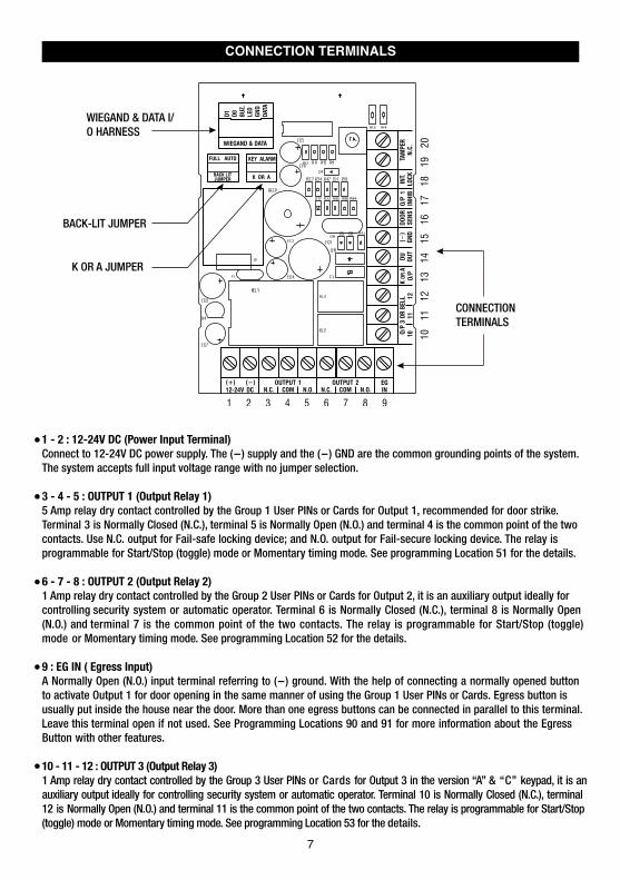
1 - 2 : 12-24V DC (Power Input Terminal)Connect to 12-24V DC power supply. The (-) supply and the (-) GND are the common grounding points of the system. The system accepts full input voltage range with no jumper selection.
3 - 4 - 5 : OUTPUT 1 (Output Relay 1)5 Amp relay dry contact controlled by the Group 1 User PINs or Cards for Output 1, recommended for door strike. Terminal 3 is Normally Closed (N.C.), terminal 5 is Normally Open (N.O.) and terminal 4 is the common point of the two contacts. Use N.C. output for Fail-safe locking device; and N.O. output for Fail-secure locking device. The relay is programmable for Start/Stop (toggle) mode or Momentary timing mode. See programming Location 51 for the details.
6 - 7 - 8 : OUTPUT 2 (Output Relay 2)1 Amp relay dry contact controlled by the Group 2 User PINs or Cards for Output 2, it is an auxiliary output ideally for controlling security system or automatic operator. Terminal 6 is Normally Closed (N.C.), terminal 8 is Normally Open (N.O.) and terminal 7 is the common point of the two contacts. The relay is programmable for Start/Stop (toggle) mode or Momentary timing mode. See programming Location 52 for the details.
9 : EG IN ( Egress Input)A Normally Open (N.O.) input terminal referring to (-) ground. With the help of connecting a normally opened button to activate Output 1 for door opening in the same manner of using the Group 1 User PINs or Cards. Egress button is usually put inside the house near the door. More than one egress buttons can be connected in parallel to this terminal. Leave this terminal open if not used. See Programming Locations 90 and 91 for more information about the Egress Button with other features.
10 - 11 - 12 : OUTPUT 3 (Output Relay 3)1 Amp relay dry contact controlled by the Group 3 User PINs or Cards for Output 3 in the version “A” & “C” keypad, it is an auxiliary output ideally for controlling security system or automatic operator. Terminal 10 is Normally Closed (N.C.), terminal 12 is Normally Open (N.O.) and terminal 11 is the common point of the two contacts. The relay is programmable for Start/Stop (toggle) mode or Momentary timing mode. See programming Location 53 for the details.
7
K OR A JUMPER
BACK-LIT JUMPER
CONNECTION TERMINALS
WIEGAND & DATA I/O HARNESS

13 : “K” OR “A” O/P (Keypad Active Output or Alarm Output)An NPN transistor open collector output with the maximum power rating of 24VDC/100mA sink. It is equivalent to an N.O. (Normally Open) terminal referring to ground. It can be used to drive small power device, such as a relay or a low power control point for other equipment. This output point is selectable to give Keypad Active Output or Alarm Output via the Selection of the “K or A” jumper.
a) Keypad Active Output (“K”) --- It switches to (-) ground for 10 seconds on each key touch. It can be used to turn on light, CCTV camera, or buzzer to notify a guard. See Application Hints for more information.b) Alarm Output (“A”) --- It switches to (-) ground while Alarm occurs in order to trigger external alarm to give
notification at remote location.
14 : DU OUT (Duress Output)An NPN transistor open collector output with the maximum power rating of 24VDC/100mA sink. It is equivalent to an N.O. (Normally Open) terminal switching to (-) ground after the Duress Code is entered. Use it to trigger an alarm zone of a security system, or turn on a buzzer to notify a guard.
15 : (-) GND (Common Ground)A grounding point of the keypad that is common to terminal 2.
16 : DOOR SENS N.C. (Door Position Sensing Input -- Normally Close)A Normally Closed (N.C.) sensing point referring to (-) ground, with the help of a normally closed magnetic contact monitors the open or close status of the door. It initiates the following functions for the system. Connect it with jumper to (-) Ground if not used.
a) Door Auto Re-lockThe system immediately re-locks the door after it is re-closed before the end of the programmed time for output 1. It prevents unwanted “tailgate” entry.
b) Door Forced Open WarningThe keypad generates “door forced open” warning and alarm instantly once the door is forced to open without a valid user PIN, Card or egress button. The warning lasts as long as the time programmed (1-999 sec). It can be stopped with an User PIN for output 1 at anytime. See programming Location 80 for the details.
c) Door Propped-up WarningThe keypad generates propped-up warning beeps (does not activates alarm output) while the door is left open longer than the allowable time programmed. The warning will last as long as the door is open until re-closed. See programming Location 81 for the details.
d) Inter-lock ControlThe inter-lock control output always goes to (-) while the door is open, which gives signal to disable the other keypad in the inter-lock system. See the Inter-lock terminal description for more information.
e) Door Opening AlarmDoor Opening Alarm is designed for the emergency door only. It is always given when the door is opened unless a valid user code or card is used prior to the door is opened. See programming Location 91 for the details.
17 : O/P 1 INHIBIT N.O. (Output 1 Inhibit Control Input – Normally Open)A Normally Open (N.O.) sensing input point for controlling the Output 1, with this terminal connecting to (-) ground, the Egress Button, the group of User PINs and Cards for Output 1 are all disabled. It is prepared mainly for the cross wire connection with the “Inter-lock O/P” point on the other keypad in an Inter-lock system.
NOTE: The inhibit function does not govern the Duress Codes and the Super User Codes. They are always valid.18 : INTER-LOCK O/P (Inter-lock Control Output)An NPN transistor open collector output with the maximum power rating of 24VDC/100mA sink. It is OFF at normal condition and it switches to (-) ground immediately for the first 5 seconds after keying in a valid User PIN or reading a card to operate Output 1, then, it will keep tying to (-) ground during the Door Position Sensor is open circuit due todoor opening. Use this output point to make cross wire connection with the other keypad’s “O/P 1 Inhibit” point in an Inter-lock system to prevent both doors can be opened at the same time.
An Inter-lock System:An inter-lock system is a two-door system that always allows only one of the doors to open during the operation. While one of the doors is opened, the other door keeps close until the open door is re-closed. It prevents the unauthorized people dashing into a protected area while the doors are in use.
8
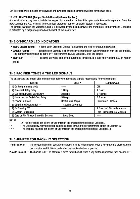
THE ON-BOARD LED INDICATORS RED / GREEN (Right) --- It lights up in Green for Output 1 activation; and Red for Output 2 activation.
AMBER (Centre) ---------It flashes on Standby. It shows the system status in synchronization with the beep tones. The standby flashing can be set to OFF in programming. See Location 73 for the details.
RED (Left) ----------------It lights up while one of the outputs is inhibited. It is also the Wiegand LED in reader
mode
THE PACIFIER TONES & THE LED SIGNALS The buzzer and the amber LED indicator give following tones and signals respectively for system status:
STATUS TONES * LED SIGNALS1) On Programming Mode ----- ON2) Successful Key Entry 1 Beep 1 Flash3) Successful Code/ Card Entry 2 Beeps 2 Flashes4) Unsuccessful Code/ Card Entry 5 Beeps 5 Flashes5) Power Up Delay Continuous Beeps Continuous Flashes6) Output Relay Activation ** 1 Second Long Beep 7) On Standby *** ----- 1 Flash in 1 Seconds Interval8) System Refreshing ----- Fast Flashes for 2.5 Minutes9) Card or PIN Already Stored in System 1 Long Beep -----
NOTE:* All Pacifier Tones can be ON or OFF through the programming option at Location 71* * The Output Relay Activation beep can be selected through the programming option at Location 72* * * The Standby flashing can be ON or OFF through the programming option at Location 73
THE JUMPER FOR BACK-LIT SELECTION 1) Full Back-lit --- The keypad gives dim backlit on standby. It turns to full backlit when a key button is pressed, then back to dim backlit 10 seconds after the last key button is pressed.2) Auto Back-lit --- The backlit is OFF on standby. It turns to full backlit when a key button is pressed, then back to OFF
An inter-lock system needs two keypads and two door position sensing switches for the two doors.
19 - 20 : TAMPER N.C. (Tamper Switch Normally Closed Contact)A normally closed dry contact while the keypad is secured on its box. It is open while keypad is separated from the box. Connect this N.C. terminal to the 24 hour protection zone of an alarm system if necessary.The tamper switch in the versions A and B is activated by the fixing screw of the front plate; in the versions C and D it is activated by a magnet equipped on the back of the plastic box.
9

FEATURE PROGRAMMING & OPERATION INSTRUCTIONSSET SYSTEM INTO PROGRAMMING MODE WITH THE MASTER CODE IMPORTANT NOTE:1) DO NOT TURN OFF POWER while the keypad is in Programming Mode. Otherwise, it may cause data lost/error to the programmed features in the memory.2) The keypad beeps after power up. Wait 1 minute until the end of the power up delay, then key in the Master Code for
setting the system into programming mode.3) For the owner’s convenience in programming at the first time, the factory has put a Master Code 0 0 0 0 into the
keypad (It is NOT a default code). To compromise security, in all cases, the owner should program a new Personal Master Code to invalidate the factory set Master Code after the keypad is owned.
4) The Button has two functions in the keypads with Door Bell button. It is a door bell button while the keypad is in normal operation; and it is equivalent to a * Button in programming mode.
MASTER CODE The Master Code can be a factory set master code or the private master code that was set by the owner.
Validate the master code with * * (or ) .2-beep confirms a valid master code. The Mains LED (Amber) is constantly ON after the system is set in the programming mode.
DIRECT ACCESS TO PROGRAMMING MODE WITH THE “DAP” CODE – 8 0 8 0 Set System Into Programming Mode With DAP Code In Case Of The Master Code Is Forgotten ! ! The owner requires to apply the following procedures precisely to set the system into programming mode with the DAP code 8 0 8 0.1) Switch OFF all the power for 1 minute to ensure that the system is fully discharged.
2) Swich ON power again. The system is in Power-up Mode for 1 minute and the buzzer gives beeps during the whole period. This is the only time limit for setting the system to Direct Access to Programming (DAP).
3) Press the Egress Button (EG IN) once first to enable the DAP function.
4) Key in the DAP Code 8 0 8 0 and validate it with * * (or ), the existing Master Code in the memory is erased and the power up beep stops. The keypad turns itself into programming mode like using the Master Code and it is ready to accept the new programming data.
5) If the Egress Button is not pressed and the DAP code is not keyed in within the power up period, the system will set itself to normal operation mode. To set it back to power-up mode, repeat procedures 1-4.
DAP CODE The DAP code is fixed on 8 0 8 0 and it is valid only in the Power-up Period after the Egress Button is pressed.Validate the DAP code with the * * (or ).2-beep confirms the system is in the Programming Mode; and the Mains LED is constantly ON.See “RECORD A MASTER CODE” at “Location 01” for the details of programming a new master code.
NOTE: If the keypad is linking up with your controller in the Split-decoded operation, it is necessary to put the controller’s “Link-up Jumper” to “ON” position to get the new Master Code for it. As the Master Code is also the link-up code of the two units. Do Not Forget to put the Link-up jumper back to OFF position after the programming. Otherwise, the controller will accept other keypads to link up with it.
0000 **
**
MASTER CODE VALIDATION
8080DAP CODE VALIDATION
.
.
.
.
.
.
.
10
EGRESS BUTTON
PRESS ONCE
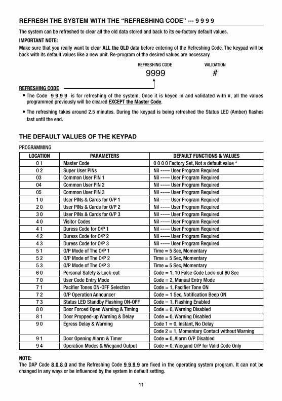
REFRESH THE SYSTEM WITH THE “REFRESHING CODE” --- 9 9 9 9 The system can be refreshed to clear all the old data stored and back to its ex-factory default values.
IMPORTANT NOTE:Make sure that you really want to clear ALL the OLD data before entering of the Refreshing Code. The keypad will be back with its default values like a new unit. Re-program of the desired values are necessary.
REFRESHING CODE The Code 9 9 9 9 is for refreshing of the system. Once it is keyed in and validated with #, all the values programmed previously will be cleared EXCEPT the Master Code.
The refreshing takes around 2.5 minutes. During the keypad is being refreshed the Status LED (Amber) flashes fast until the end.
THE DEFAULT VALUES OF THE KEYPAD PROGRAMMING
LOCATION PARAMETERS DEFAULT FUNCTIONS & VALUES0 1 Master Code 0 0 0 0 Factory Set, Not a default value *0 2 Super User PINs Nil ----- User Program Required
1 0 User PINs & Cards for O/P 1 Nil ----- User Program Required2 0 User PINs & Cards for O/P 2 Nil ----- User Program Required3 0 User PINs & Cards for O/P 3 Nil ----- User Program Required
03 Common User PIN 1 Nil ----- User Program Required04 Common User PIN 2 Nil ----- User Program Required05 Common User PIN 3 Nil ----- User Program Required
4 0 Visitor Codes Nil ----- User Program Required4 1 Duress Code for O/P 1 Nil ----- User Program Required4 2 Duress Code for O/P 2 Nil ----- User Program Required4 3 Duress Code for O/P 3 Nil ----- User Program Required5 1 O/P Mode of The O/P 1 Time = 5 Sec, Momentary5 2 O/P Mode of The O/P 2 Time = 5 Sec, Momentary5 3 O/P Mode of The O/P 3 Time = 5 Sec, Momentary6 0 Personal Safety & Lock-out Code = 1, 10 False Code Lock-out 60 Sec7 0 User Code Entry Mode Code = 2, Manual Entry Mode7 1 Pacifier Tones ON-OFF Selection Code = 1, Pacifier Tone ON7 2 O/P Operation Announcer Code = 1 Sec, Notification Beep ON7 3 Status LED Standby Flashing ON-OFF Code = 1, Flashing Enabled8 0 Door Forced Open Warning & Timing Code = 0, Warning Disabled8 1 Door Propped-up Warning & Delay Code = 0, Warning Disabled9 0 Egress Delay & Warning Code 1 = 0, Instant, No Delay
Code 2 = 1, Momentary Contact without Warning9 1 Door Opening Alarm & Timer Code = 0, Alarm O/P Disabled9 4 Operation Modes & Wiegand Output Code = 0, Wiegand O/P for Valid Code Only
NOTE:The DAP Code 8 0 8 0 and the Refreshing Code 9 9 9 9 are fixed in the operating system program. It can not be changed in any ways or be influenced by the system in default setting.
REFRESHING CODE VALIDATION
9999 #
11
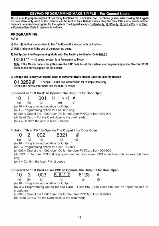
KEYPAD PROGRAMMING MAKE SIMPLE – For General Users This is a multi purpose keypad. It has many functions for user’s selection. For those general users taking the keypad for door strike only, most of the features can be kept in their Default values. Only the User PINs and a private Master Code are necessary to program for the system. The keypad accepts 1) Card only, 2) PIN only, 3) Card + PIN or 4) Card+ Common User Code to operate its outputs.
PROGRAMMINGNOTE:
a) The button is equivalent to the * button in the keypad with bell button.b) Wait 1 minute until the end of the power up delay.
1) Set System into Programming Mode with The Factory Set Master Code 0 0 0 0
0000 ** ---- 2 beeps, system is in Programming Mode
Note: If the Master Code is forgotten, use the DAP Code to set the system into programming mode. See DAP CODE 8080 on the previous page for the details.
2) Change The Factory Set Master Code to Owner’s Private Master Code for Security Reason
01 3289 # ---- 2 beeps, 3 2 8 9 is a Master Code for example here only3289 is the new Master Code and the 0000 is erased
.
12
3) Record an “EM Card” to Operate The Output 1 for Door Open
(a) (b) (c) (d) (e)(a) 10 = Programming Location for Output 1(b) 1 = Programming option for EM Card only(c) 001 = One of the 1,000 User IDs for the User PIN/Card from 000-999(d) Read Card = Put the Card close to the card reader
4) Set an “User PIN” to Operate The Output 1 for Door Open
(a) (b) (c) (d) (e)(a) 10 = Programming Location for Output 1(b) 2 = Programming option for User PIN only(c) 002 = One of the 1,000 User IDs for the User PIN/Card from 000-999(d) 8321 = The User PIN that is programmed for door open. 8321 is an User PIN for example here only
5) Record an “EM Card + User PIN” to Operate The Output 1 for Door Open10 3 003 6123 #
(a) (b) (c) (d) (e) (f)(a) 10 = Programming Location for Output 1(b) 3 = Programming option for EM Card + User PIN. (The User PIN can be repeated use or proprietary)(c) 003 = One of the 1,000 User IDs for the User PIN/Card from 000-999(d) Read Card = Put the Card close to the card reader
10 2 002 8321 #
10 1 001 #R E A D
R E A D
13
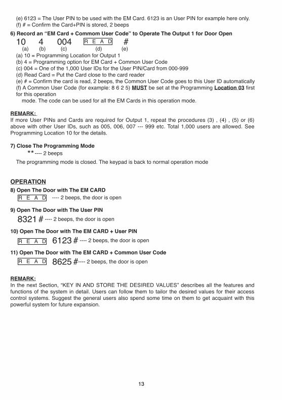
(e) 6123 = The User PIN to be used with the EM Card. 6123 is an User PIN for example here only.
6) Record an “EM Card + Commom User Code” to Operate The Output 1 for Door Open10 4 004 (a) (b) (c) (d) (e)(a) 10 = Programming Location for Output 1(b) 4 = Programming option for EM Card + Common User Code(c) 004 = One of the 1,000 User IDs for the User PIN/Card from 000-999(d) Read Card = Put the Card close to the card reader
goes to this User ID automatically(f) A Common User Code (for example: 8 6 2 5) MUST be set at the Programming Location 03for this operation
mode. The code can be used for all the EM Cards in this operation mode.
REMARK: If more User PINs and Cards are required for Output 1, repeat the procedures (3) , (4) , (5) or (6) above with other User IDs, such as 005, 006, 007 --- 999 etc. Total 1,000 users are allowed. See Programming Location 10 for the details.
7) Close The Programming Mode ---- 2 beeps
The programming mode is closed. The keypad is back to normal operation mode
OPERATION8) Open The Door with The EM CARD
---- 2 beeps, the door is open
9) Open The Door with The User PIN 8321 # ---- 2 beeps, the door is open
10) Open The Door with The EM CARD + User PIN
6123 # ---- 2 beeps, the door is open
11) Open The Door with The EM CARD + Common User Code
8625 #---- 2 beeps, the door is open
REMARK:In the next Section, “KEY IN AND STORE THE DESIRED VALUES” describes all the features and functions of the system in detail. Users can follow them to tailor the desired values for their access control systems. Suggest the general users also spend some time on them to get acquaint with this powerful system for future expansion.
R E A D
R E A D
R E A D
**
R E A D #

FEATURE PROGRAMMING -- KEY IN AND STORE THE DESIRED VALUES The feature values can be set and stored into the system one by one with the desired Programming Locations. Programming can be made continuously and it is not necessary to be in sequence order. Just go to the desired programming location and key in the value for the desired feature.
IMPORTANT NOTE --- Programming Criteria for Codes:
a) The User PINs and Codes:All the User PINs, Master Code, Duress Codes, Super User PIN Common User Codes and the Visitor User Codes are Prime Codes in the system. They can NOT be duplicated for Secondary code to work with the EM card or vice versa.
MUST be unique and can not be repeated in the programming. A prime code also
c)Warning for A Repeated Use of Prime Code or Card:One long beep is given if a User Code/PIN is keyed in or a Card is read. It means that a Prime Code or a Prime Card is repeated. The Code/PIN or Card was already in one of the PIN or Card Locations or IDs. The programming is invalid. Change a new Code/PIN or Card and program it again.
g) Make A List Recording of The User Names VS User Codes:Suggest the owner to make a list recording of the User Names corresponding to the Codes/PINs/Cards that are going to store in the Locations and the IDs before the programming. It will be a useful tool for the owner to easily program them smoothly and also to trace them from this multi-users system in the future.
13
b) The Prime Cards:All the EM Cards used in this system are Prime Cards. The cards used for the Outputs 1, 2 and 3 MUST be unique and can not be repeated use for different Outputs in the programming. The Card always has the priority to be read when working in “EM Card + Secondary PIN” or "EM Card + Common User PIN”.
d)Secondary User PINs:The Secondary User PINs are prepared to enhance security. It is put after a Card in “EM Card + Secondary User PIN” programming. They can be a repeated code within the Secondary PINs but it is NOT allowed a duplicate of the Prime Codes. The system will reject a duplicated Prime Code for Secondary User PIN or vice versa.
e)Getting Advantages from The Secondary User PINs:The repeated Secondary PINs can be used as a Group Common User Code or called Department User Code for a group of EM Cards, which simplifies the programming of using large number of different User PINs. EM Card with Department Code prevents a lost card used by people of other department. Also, it will be easier to trace out the department of the lost card belongs to. Of cause, the owner can use a proprietary Secondary User PIN for each EM Card in the “EM Card + Secondary User PIN” programming to further increase the security if it is the main concern.
f) Security Level Comparison of The Secondary User PIN/Code following Card Reading:i ) E M C a r d + C o m m o n U s e r C o d e - - - A l l E M C a r d s u s e t h e s a m e U s e r C o d e . S e c u r i t y l e v e l i s b e t t e r t h a n j u s t C a r d
only. A lost Card picked up by any people can be used if he knows the Common User Code.i i ) E M C a r d + D e p a r t m e n t U s e r C o d e - - - T h e E M C a r d s a r e d i v i d e d i n t o g r o u p s w i t h a D e p a r t m e n t U s e r C o d e . A l o s t
Card can be used only by the people in the same group who know the Department Code.i i i ) E M C a r d + S e c o n d a r y U s e r P I N - - - E a c h E M C a r d h a s i t s o w n p r o p r i e t a r y U s e r P I N . A l o s t C a r d c a n n o t b e u s e d
by other people.

15
Example: User Name Location Function Code User ID PIN/Code Card # Remark12345678910111213141516--
RECORD A MASTER CODE (Location 01)
MASTER CODEMaster Code is the authorization code for setting the system to programming mode. It is NOT an User Code operating of the output relays.The Master Code can be 4 to 8 digits. Press # key to confirm code entryWhen a new master code is keyed in and confirmed, the old master code is replaced automatically.The master code is also the Link-up Code between the keypad and the optional controller of the system in Split-decoded operation.Example: Set a Master Code with the number of “2 2 3 3” ----
RECORD A SUPER USER PIN (Location 02) The Super User PIN has TWO functions. It is prepared for the owner to simply use only one User PIN to operate the three outputs of the keypad and make operation inhibit enable / disable to the system outputs.
SUPER USER PINThe Super User PIN can be 4 to 8 digits.Two beeps will be heard after pressing the # key to confirm code entry.When a new Super User PIN is keyed in and confirmed, the old one is replaced.Example: Set a Super User PIN with the number of “2 5 8 0” ----To deleted a Super User PIN from memory: Key in just the Location number and #. ----
4 to 8 Digits
SUPER USER PIN VALIDATIONLOCATION
02
02 2580 #02 #
#
4 to 8 Digits
MASTER CODE VALIDATIONLOCATION
01
01 2233 #
#

16
OPERATION AND FUNCTIONS OF THE SUPER USER PIN 1) Operate Output 1, 2, and 3
The operation of the Super User PIN is just like a normal User PIN. Simply key-in the PIN with a specific output number for the desired Output. The Super User PIN can also be used to reset an operating output timer instantly.
---------- Output 1 Activates or Output 1 Resets
---------- Output 2 Activates or Output 2 Resets
---------- Output 3 Activates or Output 3 Resets
2) Inhibit The User PINs For Output 1The Super User PIN can also be used to inhibit the normal User PINs/Cards for the Output 1 (usually they are for door strike). It enhances the security level of the access control system, such as to stop a keypad after office hour or while the house is nobody inside. Once the Output 1 is inhibited, the User PINs/Cards for it become invalid and those people even know the User PINs are refused during the system is inhibited. The inhibit function is toggled in Start / Stop mode with the following code entry.
---------- The Whole Group of User PINs & Cards for Output 1 are Disabled or Enabled in Toggle
SUPER USER PIN
SUPER USER PIN
SUPER USER PIN
SUPER USER PIN
# 1# 2# 3
# 9
NOTE:
The inhibit function setting with the Super User PIN applies to the whole group of User PINs and Cards for , Output 1 but not for Output 2 or Output 3.
For safety reason, the inhibit function initiated with the Super User PIN does not govern the Egress Button. The door still can be opened with it from inside.
The Super User PINs are always valid. They are not governed by any inhibit or lock-out function in the system.
ONLY
RECORD THE COMMON USER PINS FOR OUTPUT 1, 2 & 3 (Locations 03, 04, & 05) The Common User PINs 1, 2 and 3 are prepared for operating of the Output 1, Output 2 and Output 3 respectively as an enhance code. The Common User PINs MUST work in the form of “Card + Common PIN” to operate the outputs to increase the security of the access control system. See Locations 10, 20 & 30 for more information.NOTE : Common User PIN alone can NOT be used to operate the Outputs directly.
COMMON USER PIN LOCATIONS-- Location Stores The Common User PIN for Output 1-- Location Stores The Common User PIN for Output 2-- Location Stores The Common User PIN for Output 3
COMMON USER PINS.
4 to 8 Digits COMMON USER VALIDATIONLOCATIONS
030405 #03 - 05

Total of 1,200 User PINs and/or Cards are available for the 3 user groups to control the 3 outputs.
1) 1,000 ---- for Output 1 (Group 1)2) 100 ------ for Output 2 (Group 2)3) 100 ------ for Output 3 (Group 3)
The Private User PINs and Cards in the 3 user groups PINS in the “EM Card + Secondary User PIN” can be repeated.
MUST be unique. Repeated PINs will be rejected. Secondary User
USER GROUP LOCATIONS – Group 1 --For User PINs/Cards Controlling Output 11,000 Users are allowed in group 1 for O/P 1
– Group 2 --For User PINs/Cards Controlling Output 2100 Users are allowed in group 2 for O/P 2
– Group 3 -- For User PINs/Cards Controlling Output 3100 Users are allowed in group 3 for O/P 3
SELECTION OF OPERATION MEDIA
USER ID NUMBERA 3-digit ID is an identified number for each User PIN.Repeated ID number will be rejected by the system
a) ID Number 000 - 999 for 1,000 User PINs to operate Output 1
b) ID Number 001 - 100 for 100 User PINs to operate Output 2
c) ID Number 001 - 100 for 100 User PINs to operate Output 3
CARD &/OR USER PINS
The User PINs can be 4-8 digits. Key in the User PIN on each ID Number box, then confirm it with # key.
17
10
20
30
USER PIN
10-30 2or5 000-999 #VALIDATIONLOCATIONS RECORD/DELETE USER ID
USER PIN
RECORD-DELETE USER PINS OR CARDS FOR OUTPUT 1, 2, & 3 (Locations 10, 20 & 30)
Number 1, 2, 3 or 4 represents the Media to be used to operate the keypad.Number 5 is the authorization code for deleting of an PIN and/or Card fromits User ID.
= EM Card only; = Private User PIN only;
= EM Card + Secondary User PIN = EM Card + Common User PIN
= Delete an User PIN &/or Card from the selected User ID number
= Clear all the PINs & Cards from the selected Location. It takes few seconds to a minute to complete depending on the Location selected and the data stored.Please see the programming example below for the details.
1 23 450999
Just simply put the EM card close to the reader window to read it on each ID Number box, then, confirm it withCard ONLY, or Card + Common User PIN entry. The Common User PIN is NOT required to # key if it is a
key-in here. It will go into its location automatically after the Card is read.
Read the Card first, then key in the Secondary User PIN on each ID number box, then confirm it with # key if it is aCard + Secondary User PIN. The Secondary User PINs can be duplicated or a proprietary User PIN but can not be a duplicate of a Prime Code. Owner can use the same secondary User PIN for a group of Cards as a group Common User Code (or called Department Code) for a specific relay output.
Cards (Operation Media # 1, 3, & 4) and Private User PINs (Operation Media 2) MUST be unique. A repeated EM card or Private User PIN will be rejected and one long beep will be generated by the system to notify the owner.
18
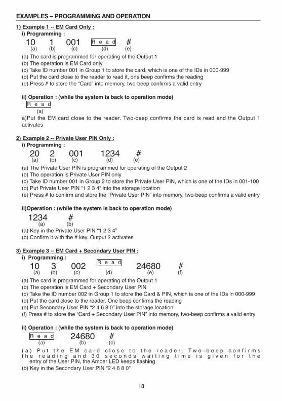
EXAMPLES – PROGRAMMING AND OPERATION 1) Example 1 -- EM Card Only :
i) Programming :10 1 001 #
(a) (b) (c) (d) (e)(a) The card is programmed for operating of the Output 1(b) The operation is EM Card only(c) Take ID number 001 in Group 1 to store the card, which is one of the IDs in 000-999
ii) Operation : (while the system is back to operation mode) (a)a)Put the EM card close to the reader. Two-beep confirms the card is read and the Output 1 activates
2) Example 2 -- Private User PIN Only :i) Programming :
20 2 001 1234 # (a) (b) (c) (d) (e)(a) The Private User PIN is programmed for operating of the Output 2(b) The operation is Private User PIN only(c) Take ID number 001 in Group 2 to store the Private User PIN, which is one of the IDs in 001-100(d) Put Private User PIN “1 2 3 4” into the storage location
ii)Operation : (while the system is back to operation mode)
1234 # (a) (b)(a) Key in the Private User PIN “1 2 3 4”
3) Example 3 -- EM Card + Secondary User PIN :i) Programming :
10 3 002 24680 # (a) (b) (c) (d) (e) (f)(a) The card is programmed for operating of the Output 1(b) The operation is EM Card + Secondary User PIN(c) Take the ID number 002 in Group 1 to store the Card & PIN, which is one of the IDs in 000-999
(e) Put Secondary User PIN “2 4 6 8 0” into the storage location(f) Press # to store the “Card + Secondary User PIN” into memory
ii) Operation : (while the system is back to operation mode) 24680 #
(a) (b) (c)( a ) P u t t h e E M c a r d c l o s e t o t h e r e a d e r . T w o - b e e p c o n f i r m s t h e r e a d i n g a n d 3 0 s e c o n d s w a i t i n g t i m e i s g i v e n f o r t h e
(b) Key in the Secondary User PIN “2 4 6 8 0”
R e a d
R e a d
R e a d
R e a d

19
4) Example 4 -- EM Card + Common User PIN :i) Programming :10 4 003 #
(a) (b) (c) (d) (e)(a) The card is programmed for operating of the Output 1(b) The operation is “EM Card + Common User PIN”(c) Take ID number 003 in Group 1 to store the card, which is one of the IDs in 000-999(d) Put the card close to the reader. One beep confirms the reading. (No need to key in a Common User PIN but
there MUST be a Common User PIN already recorded in Location 03; (or 04, 05 if for O/P 2, O/P (e) Press # to store the “Card” into memory. Two-beep confirms a valid entry
a) Put the EM card close to the reader. One-beep confirms the reading and 30 seconds waiting time is given for the entry of the Common User PIN, the Amber LED keeps flashing.
c) Confirm it with the # key. Output 1 activates.
ii) Operation : (while the system is back to operation mode)
# (a) (b) (c)
b) Key in the Common User PIN “1 3 5 7” (the number programmed in “Location 0 3” for Output 1 in the previous Example)
5) Example 5 -- Delete an User PIN & / or EM Card (for O/P 1, 2 or 3) :i) Delete An User PIN or A Lost EM Card10 5
(a) (b) (c) (d)a) Key in the User Group that the User ID belongs to. “10” for the Group 1, “20” for the Group 2, and “30” for the Group 3
b) Key in “5” that is the Command Code for making a deletion herec) Key in the User ID that stored the User PIN, the lost EM card or the EM Card+User PINd) Press the # key. Two-beep confirms a valid entry and the PIN and/or Card in that User ID is cleared
ii) Delete an EM Card10 5 #
(a) (b) (c) (d)a) Key in the User Group that the EM Card belongs to. “1 0” for the Group 1, “2 0” for the Group 2, and “3 0” for the
Group 3b) Key in “5” that is the Command Code for making a deletion herec) Put the EM card close to the reader. One-beep confirms the reading. Read the Card only also makes a valid
d) Press the # key. Two-beep confirms a valid entry. The EM Card in that USER ID is cleared. Key in the User ID is deletion to the Card working with the Common User PIN or the Secondary User PIN
not required.
6) Example 6 – Clear The Whole Group of Users :Whole group of users including the PINs and Cards can be cleared with the following command.
10 0999 # (a) (b) (c)
a) The User Group 1 – “10 ” is selected to be cleared. “20 ” for Group 2 & “ 30 ” for Group 3
R e a d
User ID
R e a d
Common User R e a d
b) Key in the Group Deletion Command, 0 9 9 9c) Confirm the deletion with #. All the User PINs and Cards in the Group 1 are cleared. It takes few seconds to a
minute to complete depending on the data stored.
#

VISITOR CODES (FOR OUTPUT 1 ONLY) (Location 40) The Visitor Codes are the temporary user codes for operating of the Output 1 (mainly for door strike in access control). They can be programmed as “One Time Codes” or “Codes with Time Limit”. The Visitor Codes will be cleared automatically after use if they are one time codes, or, when the allowed time expires.
VISITOR ID
50 Visitor IDs for storing the codes. They are represented by a
Two-digit ID Number of 01 to 50 .
0999 = Clear all the Visitor Codes from Location 40. Pleasesee the Programming example below for the details.
VALID PERIOD
The codes in this box MUST be two digits and they represent the time of the operation.
00 --- One Time Code
One Time Code has no time limit but it can only be used for ONCE.It is cleared by the system automatically after use.
01-99 --- Time Limit in Hour(s)
The Visitor Code can be set with the valid time limit of 1 Hour to 99 Hours with atwo-digit number of 01 to 99. The visitor code is cleared by the system when the time limit reaches.
VISITOR CODES
When a new Visitor Code is put in the same Code box, the old code is replaced.The Visitor Codes can be 4-8 digits for the Manual Mode code entry.The Visitor Codes MUST be in the same digit length with the Master Code for Auto Mode code entry.The Visitor Codes can not reset Duress Output.
NOTE: All Visitor Codes will be cleared after power down to prevent extension/confusion of their valid time limit.
EXAMPLES: (Please see the following page)
20
4-8 DIGITS40 #01-50 00 or 01-99VISITOR CODE VALIDATIONLOCATION VISITOR ID VALID PERIOD

Example 1: Set a “One Time Visitor Code” with the number of “1 2 6 8” for the Output 1
40 01 00 1268 # (a) (b) (c) (d) (e)
(a) Visitor Code Programming, (b) The Visitor ID, (c) An One Time Code, (d) The Visitor Code, (e) Entry Confirmation
Example 2: Set a “Visitor Code” with the number of “1 3 7 8” that is valid for three hours for the Output 1
40 02 03 1378 # (a) (b) (c) (d) (e)
(a) Visitor Code Programming, (b) The Visitor ID, (c) Valid for 3 Hours, (d) The Visitor Code, (e) Entry Confirmation
Example 3: Delete a “Visitor Code” from Vistor ID 02 in the memory
40 02 #
(a) (b) (c)
(a) Visitor Code Programming, (b) The Visitor ID, (c) Delete Confirmation
Example 4: Clear all “Visitor Codes” from Location 4040 0999 #
(a) (b) (c)
(a) Visitor Code Location, (b) The Deletion Command Code, (c) Confirmation, all Visitor Codes are cleared
DURESS CODES (FOR OUTPUTS 1, 2 & 3) (Location 41, 42 & 43) The Duress Codes are prepared for those Important Persons in case of DURESS while he operates the access control keypad. The duress code operates like a normal User PIN for Output 1, 2 or 3, and at the same time activates the Duress Output without any indication. The user may use it to report an emergency and ask for help silently when he is forced to operate the keypad if the Duress Output is connected with a security system.
NOTE: The Duress Codes are always valid. They are not governed by any inhibit or lock-out function in the system.
OUTPUT LOCATIONS
41 – Duress Codes for Output 1
42 – Duress Codes for Output 2
43 – Duress Codes for Output 3
DURESS CODE IDs
ID 01-50 50 Duress Codes Are Allowed for The Output 1
ID 01-10 10 Duress Codes Are Allowed for The Output 2
ID 01-10 10 Duress Codes Are Allowed for The Output 3
0999 = Clear all the Duress Codes from the selected Location group. Please see the programming example below for the details.
THE DURESS CODES
50, 10 and 10 Duress Codes can be programmed for Output 1, 2 and 3 respectively. They are stored in their two-digit Code ID box. When a new Code is put into the same Code ID box, the old code is replaced.
The Duress Codes are 4-8 digits for Manual Mode code entry.The Duress Codes MUST be in the same digit length with the Master Code for Auto Mode code entry.Always set a Duress Code that is easy to remember in
The Duress Code can also be used to replace the Secondary User PIN or Common User PIN Card reading for the Duress reporting.
Panic Situation. Only one number different from the daily used User PIN is highly recommended.
Example: User PIN is 1 3 6 9, then 3 3 6 9 or 1 3 6 0 might be a good choice for the Duress Code.
21
41-43 01-50 #4-8 DIGITS
DURESS CODE VALIDATIONLOCATIONS CODE ID

EXAMPLES:
Example 1: Set a “Duress Code” with the number of “3 3 6 9” for Output 1
41 01 3369 # (a) (b) (c) (d)
(a) Duress Code Programming for Output 1, (b) Duress Code ID, (c) The Duress Code, (e) Entry Confirmation
Example 2: Set a “Duress Code” with the number of “2 3 9 8 0” for Output 2
42 01 23980 # (a) (b) (c) (d)
(a) Duress Code Programming for Output 2, (b) Duress Code ID, (c) The Duress Code, (e) Entry Confirmation
Example 3: Delete an Output 1 “Duress Code” from Duress Code ID 01 in the memory
41 01 # (a) (b) (c)
(a) Duress Code Programming for Output 1, (b) The Duress Code ID, (c) Delete Confirmation
Example 4: Clear The Whole Group of Duress Codes from Location 41 :
41 0999 #
(a) (b) (c)
(a) Group Location 41, (b) The Group Deletion Command, (c) Confirmation, all Duress Codes in Location 41 are cleared.
THE OPERATION AND FUNCTION OF THE DURESS CODE The Duress Code(s) has double actions when it is keyed in. It activates the Duress Output (for duress alarm) and at the same time activates the specific Relay Output 1, 2 or 3 just like a normal User PIN. The Duress Code always activates its Relay Output in its group, but, does not de-activate (stop) the Duress Output. ONLY a normal User PIN or Card in any one of the user groups, or a Super User PIN can reset (de-activate) the Duress Output.
For Example:
Key in The Duress Code 3 3 6 9 of the Group 1 (for Output 1) To Command The Duress Function :
3369# ----- Duress Output activates (switches to (-) ground) & Output 1 activates.
Key in The Duress Code 3 3 6 9 in Group 1 (for Output 1) Again :
3369# ----- Duress Output keeps activating and no change in its state (keeps to (-) ground) & Output 1 activates again.
Key in A Normal User PIN 1 3 6 9 in Group 1 (for Output 1):
1369# ----- Duress Output resets (back to OFF state) but has no function on Output 1.
22
Report Duress in EM Card OperationThe Duress Codes are Prime User Codes in the system. In the “EM Card + Secondary User PIN” or “EM Card + Common User PIN” operation, they can be used to replace the “Secondary User PIN” or
is not required. The system has the function automatically while Duress Code exists.
Operation : Taking Duress Code 3 3 6 9 in Group 1 for Output 1 As Example3369 #
(a) (b) (c)

CONFIGURATION OF THE OUTPUT MODES OF OUTPUT 1, 2 AND 3 (Locations 51, 52 & 53) The three relay outputs of this keypad are programmable for Start/Stop or Timing modes. Apart from the door access control, alarm arm-disarm control, they are also universal timers for automatic operators in industry with their 99,999 seconds (over 24 hours) programmable timer.
OUTPUT LOCATIONS
51 -- Location for Output 1
52 -- Location for Output 2
53 -- Location for Output 3
OUTPUT MODE & TIMING
0 – Start /Stop Mode (Toggle)
The number 0 sets the output to the Start / Stop mode. The output Starts when an User PIN and/or Card is entered/read; the output Stops when an User PIN and/or Card is entered/read again.
1-99999 Seconds Momentary --- (Default -- Momentary 5 Seconds)
The output can be set in Momentary Mode with the time of 1 second to 99,999 seconds. The output will reset automatically when the time expires OR it can be RESET manually at anytime with the Super User Code that operates the desired output before the end of the time.
Example : Reset Output 1 -- # 1 ------------- Output 1 resets
Reset Output 2 -- # 2 ------------- Output 2 resets
Reset Output 3 -- # 3 ------------- Output 3 resets
PERSONAL SAFETY AND SYSTEM LOCK-OUT (Location 60)
SAFETY & LOCK-OUT OPTIONS
The Options are represented by their Mode Numbers in programming. They are described below:
1 --- After 10 successive false Card/User Code trials, the keypad locks during 60 seconds. -- (Default)
2 --- After 10 successive false Card/User Code trials, activates the Duress output to switch to ( -) ground.The Duress Output can be released with any user PIN or Card in the User Group 1 or the Super User PIN.
5 - 10 ---Selection of after 5 to 10 successive Card/User Code trials, the keypad locks during 15 minutes.
The keypad can be reset to release the lock-out with the “Super User Code” in the following way.
Example : Release the lock-out -- # 9
00 --- Disappearance of all the above lock-out securities.
SUPER USER CODE
SUPER USER CODE
SUPER USER CODE
1 to 2 Digits
LOCK-OUT MODES VALIDATIONLOCATION
60 #
SUPER USER CODE
OUTPUT MODE & TIME VALIDATIONLOCATIONS
51-53 0 or 1-99999 #
23
a) Put the EM card close to the reader. One-beep confirms the reading and 30 seconds waiting time is given for the entry of the Duress Code, the Amber LED keeps flashing.
b) Key in the Duress Codes 3 3 6 9 for operating the Output 1c) Confirm it with the # key. Output 1 activates in a normal
ENTRY MODES VALIDATIONLOCATION
1 or 270 #
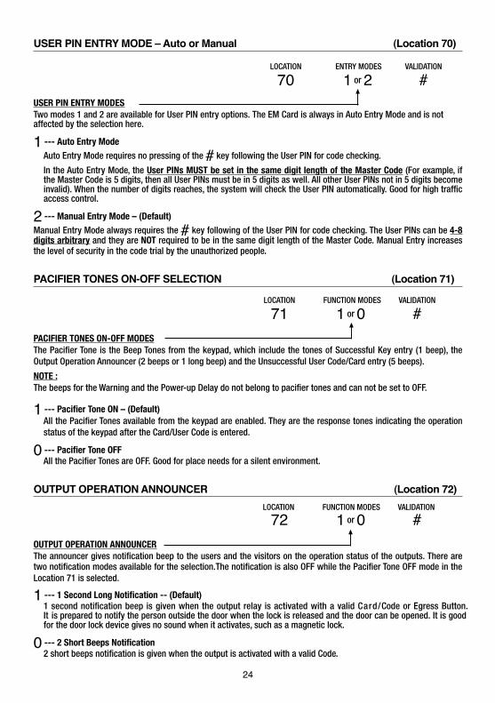
USER PIN ENTRY MODE – Auto or Manual (Location 70)
USER PIN ENTRY MODESTwo modes 1 and 2 are available for User PIN entry options. The EM Card is always in Auto Entry Mode and is notaffected by the selection here.
1 --- Auto Entry ModeAuto Entry Mode requires no pressing of the # key following the User PIN for code checking.
In the Auto Entry Mode, the User PINs MUST be set in the same digit length of the Master Code (For example, if the Master Code is 5 digits, then all User PINs must be in 5 digits as well. All other User PINs not in 5 digits become invalid). When the number of digits reaches, the system will check the User PIN automatically. Good for high traffic access control.
2 --- Manual Entry Mode – (Default)Manual Entry Mode always requires the # key following of the User PIN for code checking. The User PINs can be 4-8 digits arbitrary and they are NOT required to be in the same digit length of the Master Code. Manual Entry increases the level of security in the code trial by the unauthorized people.
PACIFIER TONES ON-OFF SELECTION (Location 71)
PACIFIER TONES ON-OFF MODESThe Pacifier Tone is the Beep Tones from the keypad, which include the tones of Successful Key entry (1 beep), the Output Operation Announcer (2 beeps or 1 long beep) and the Unsuccessful User Code/Card entry (5 beeps).
NOTE :The beeps for the Warning and the Power-up Delay do not belong to pacifier tones and can not be set to OFF.
1 --- Pacifier Tone ON – (Default)All the Pacifier Tones available from the keypad are enabled. They are the response tones indicating the operation status of the keypad after the Card/User Code is entered.
0 --- Pacifier Tone OFFAll the Pacifier Tones are OFF. Good for place needs for a silent environment.
OUTPUT OPERATION ANNOUNCER (Location 72)
OUTPUT OPERATION ANNOUNCERThe announcer gives notification beep to the users and the visitors on the operation status of the outputs. There are two notification modes available for the selection.The notification is also OFF while the Pacifier Tone OFF mode in the Location 71 is selected.
1 --- 1 Second Long Notification -- (Default)1 second notification beep is given when the output relay is activated with a valid Card/Code or Egress Button. It is prepared to notify the person outside the door when the lock is released and the door can be opened. It is good for the door lock device gives no sound when it activates, such as a magnetic lock.
0 --- 2 Short Beeps Notification2 short beeps notification is given when the output is activated with a valid Code.
FUNCTION MODES VALIDATIONLOCATION
FUNCTION MODES VALIDATIONLOCATION
1 or 0
1 or 0
#
#
71
72
24

STATUS LED FLASHING ON-OFF DURING STANDBY (Location 73)
STANDBY FLASHING ON-OFF
Some people find the flashing light of the status LED (the amber LED) is annoying during the keypad is on standby, especially at the night time. The standby flashing can be ON-OFF with the setting here.
1 --- Standby Flashing ON -- (Default)The Status LED gives Standby Flashing all the time during the keypad is on standby. It also gives all the light indications showing the operation status of the system.
0 --- Standby Flashing OFFThe Standby Flashing is disabled but it does not affect the system status indications. All the light indications from it are unchanged.
DOOR FORCED OPEN WARNING & TIMING (Location 80)
DOOR FORCED OPEN WARNING ON-OFF & TIMING
The Door Forced Open Warning function requires a Door Position Sensing switch (usually a magnetic contact) to work with. Once a Timing Figure is put into the Function Mode box, the warning mode is enabled.
0 --- Door Forced Open Warning OFF – (Default)
1 - 999 --- Door Forced Open Warning & Alarm ON & Timing
The Timing Figure for the Warning can be 1-999 seconds. The keypad generates the door forced open warning beeps and activates the alarm output (Terminal 13) instantly if the door is forced to open without a valid User PIN or pressing of the Egress Button. The beeps and alarm will last as long as the time set on the timer and it can be stopped at anytime with an User PIN/Card in Group 1 before the end of the time.
The Manner of The Door Forced Open Warning:
a) The door is forced to open (without using PIN or Egress Button) – Warning & Alarmb) The door is opened with PIN/Card – No Warning or Alarmc) The door is opened with Egress Button – No Warning or Alarm
DOOR PROPPED-UP WARNING & THE DELAY TIME (Location 81)
DOOR PROPPED-UP WARNING ON-OFF & TIMING
If somebody opened the door and it is left open longer than the allowable delay time, the keypad will generate door propped-up warning until the door is re-closed. There is warning beeps from the keypad only but does not activates the alarm output.
0 --- Door Propped-up Warning OFF – (Default)
1 - 999 --- Door Propped-up Warning ON & The Delay Time
The Delay Time can be 1 to 999 seconds. It is the time allows the door to open without starting of the warning.
FUNCTION MODES
FUNCTION MODES
VALIDATION
VALIDATION
LOCATION
LOCATION
0 or 1 - 999
0 or 1 - 999
#
#
80
81
FUNCTION MODES VALIDATIONLOCATION
1 or 0 #73
25

INTELLIGENT EGRESS BUTTON – AN UNIQUE FEATURE OF A CONTEMPORARY KEYPAD Most of the keypads for access control are just for controlling of “Going In” from outside. It is not enough for today’s access control systems. In fact, controlling of “Going Out” is also very important in many public passage areas. They are not allowed to use locks or digital keypads for stopping of “Going Out” due to safety reasons. Such as hospitals, kindergartens, elderly homes, convenient stores, emergency exits etc.. The wardens, teachers, shopkeepers and the guards are always required to keep an eye on people to prevent unattended leaving, shoplifting, and illegal use of the emergency exits.
The Intelligent Egress Button can be programmed to do something to get the attention of the person on duty before the door is opened. The button offers programmable egress delay, delay with warning, holding button required for the delay, momentary button contact with warning for the delay and even gives alarm when a controlled door is opened.
Locations 90 and 91 below are the places for setting the desired functions for the Egress Button.
The functions programmed to the Egress Button do not affect the normal operation of the system with its keypad. For the safety consideration, the operation of the keypad with PIN, Code or Card is always in the first priority to give instant action to the output relay 1 for door strike.
It is NOT required to program the Egress Button with the special function in normal use. Just leave it on its default values.
WHERE AND WHY “GOING OUT” NEEDS ATTENTIONExamples for some areas may need an Intelligent Egress Button:
Hospital:Some of the patients are not allowed to leave the ward without doctor’s permission. An egress button with exit delay and warning beeps will help the nurse or warden to get the attention to the door when the egress button is pressed. Further setting of the egress button with holding contact for the delay even gives higher level of security to a controlled door.
Kindergarten:Young children are always active. Some of them may be willing to go out to explore their ways of playing. For safety reason, teachers have to watch all of them in the attended area. Leaving school alone without the companion of parents or teacher is dangerous to the young children. An egress button with delay and warning beeps will be helpful to prevent the children trying to go out without getting the attention of the teacher.
Elderly Home:Elderly needs constant attention and care. Some old people have poor memory. They may forget the way to come back if they leave home alone. An egress button with delay and warning beep will easily get the attention of the warden before the door is open.
Convenient Store:Most of the convenient stores have just only one or two shopkeepers on duty. They are usually the cashier. Shoplifting may easily happen while the shopkeeper is busily serving customers at the cashier desk. A holding contact egress button with delay and warning beeps may help to stop most of the shoplifting. As the thief knows that he is gotten attention by the shopkeeper before the door is open.
High Traffic Passage:A short buffer time may be necessary for opening a door outward after pressing the egress button for those exits open to a high traffic passage. An egress button with short delay and warning beeps helps the user to pay attention to the people passing by to prevent hitting them when the door is pushed outward.
Emergency Exit:Emergency Exit is not open to the public for daily use. It is for emergency case only. It is usually closed and watched by the security guards. The egress button of this keypad can be programmed to offer exit delay with warning beeps and even gives alarm output to trigger an alarm system when the door is forced to open or the door is open after the exit delay expired. It is an useful tool to get the attention of the person on duty.
26

EGRESS DELAY , WARNING AND ALARM (Location 90)
CONFIGURATIONS OF THE EGRESS WARNING AND ALARM
Key in the number to enable 1 of the 6 configurations described below:
1 --- Momentary Contact Mode without Warning -- (Default)• Press the Button once. No warning or alarm is given during Egress Delay.• Good for silent area. The people have to wait for the door open until the delay time
reaches.
2 --- Momentary Contact Mode with Warning Beep• Press the Button once. The system gives Warning Beeps during the Egress Delay.• Good for the place required attention. The keypad beeps during the people are waiting
for the door open.
3 --- Momentary Contact Mode with Warning Beep & Alarm• Press the Button once. The system gives Warning Beeps and also activates its Alarm O/P
during the Egress Delay• Good for door for the authorized people only. The keypad beeps and report alarm to a
security system during the people are waiting for the door open. • This is usually an “Emergency Exit”. The door can be opened with the Keypad without
triggering of the Buzzer and Alarm Output.
4 --- Holding Contact Mode without Warning• Press and hold the Button. No warning or alarm is given during the Egress Delay.• Good for the silent area. The people require to press & hold the button until the delay
time reaches for the door open.
5 --- Holding Contact Mode with Warning Beep• Press and hold the Button. The system gives Warning Beeps during Egress Delay.• Good for the place required attention. The keypad beeps while the button is kept pressed
during the people are waiting for the door open.
6 --- Holding Contact Mode with Warning Beep & Alarm• Press and hold the Button. The system gives Warning Beeps and also activates its Alarm
O/P during Egress Delay.• This is usually an “Emergency Exit”. The door can be opened with the Keypad without
triggering of the Warning and Alarm.
EGRESS DELAY TIMER
0 --- No Delay – (Default)Output 1 activates instantly (the door is released instantly) when the Egress Button is pressed.
1 – 99 --- Egress Delay TimingPut any number of 1 to 99 into the box to enable the Egress Delay. The number is the time in second, which starts to count when the Egress Button is pressed. Output 1 activates (the door is released) when the delay time reaches.
NOTE:1) Momentary Contact -- The Egress Delay starts to count when the egress button is momentarily pressed. Output 1 activates automatically (door is released) when the delay time reaches.2) Holding Contact -- The user MUST hold the egress button in contact for the whole period of the Egress Delay time until Output 1 activates. If the egress button is released before the end of the Egress Delay, the timer will stop to count and reset.3) The Egress Delay does not affect the operation of the User PINs for Output 1. The User PINs always give INSTANT action.
Example: (Please see the following page)
FUNCTION MODES VALIDATIONDELAY TIMELOCATION
1 - 6 0 or 1 - 99 #90
27

EXAMPLES:Example 1: Set Egress Button in Momentary contact 5 seconds with delay & warning beep
90 2 5 # (a) (b) (c) (d)
(a) Egress function programming, (b) Momentary contact with warning, (c) Delay time of 5 seconds to release door, (d) Entry confirmation
Example 2: Set Egress Button in Holding contact of 10 seconds with warning beep
90 5 10 # (a) (b) (c) (d)
(a) Egress function programming, (b) Holding contact mode with warning, (c) Holding time of 10 seconds to release door, (d) Entry confirmation
Example 3: Set Egress Button in Momentary contact without delay (This is the default setting)
90 1 0 # (a) (b) (c) (d) (a) Egress function programming, (b) Momentary contact without delay, (c) Release door instantly, (d) Entry confirmation
DOOR OPENING ALARM & TIMER (Location 91)
ALARM & TIMING OF DOOR OPENING
0 --- No Alarm – (Default)The Alarm Output is disabled
1 – 999 --- Alarm TimerThe Door Open Alarm operates the Alarm Output (Terminal 13) only. It is mainly prepared to trigger an optional alarm system. Put any Timing Figure of 1 to 999 into the box to enable the function of the Door Opening Alarm. The figure is the time in second of the alarm duration, which starts to count after the door is opened and it resets automatically when the time reaches.
The alarm can be stopped with the User Codes/Cards or the Super User PIN for Output 1 at any time before the end of the alarm time.
NOTE: The Door Opening Alarm is designed to protect the emergency exit door from use by the un-authorized person. The alarm occurs when the door is opened or forced to open. However, Alarm will not happen if the door is opened with a valid User Code or Card.
The Manner of The Door Opening Alarm:a) The door is forced to open without using PIN/Card – Alarmb) The door is opened with Egress Button – Alarmc) The door is opened with PIN/Card – No Alarm
To prevent confusion of the alarm outputs. It is suggested to disable the "Door Forced Open Warning" at Location 80 while "Door Opening Alarm" function is enabled. If both functions at Location 80 and Location 91 are enabled and are set with different timings, the system will combine them and will take the longer one for alarm time.
CLOSE THE PROGRAMMING MODE ( * * ) Always close programming mode with * * to set system back to normal Operation after programming.
The button is equivalent to the * button in the keypad with bell button.
VALIDATION
** ------------------------------- System is back to normal operation mode
ALARM TIME VALIDATIONLOCATION
0 or 1 - 99991 #
.
28

THE WIRE HARNESS FOR “WIEGAND DATA OUTPUT” & “Transmitter Solutions DATA I/OO”
NOTE: The information in this section is NOT for the system in Stand Alone operation. It is not necessary to plug in the wire harness to the socket, just leave it open.
The information below is for setting the keypad unit with the Wiegand data interface to a control panel, or the Transmitter Solutions Data I/O interface to an Transmitter Solutions Controller to make up a high security split-decoded system.
Split-decoded Keypad SystemMost of the general purpose keypads on the market are self-contained systems for stand alone operation. It controls the appliance(s) directly with its output relay contact(s); such as the electric lock in an access control system. The electric lock is connected to the keypad that is installed outside the house. The thief can open the door without a code or card but just open the keypad box and make contact to the output relay terminal. It is a safety drawback in security.
The high security systems are usually operating in the Split-decoded mode that combines an outside unit for card reading and code entry; and a control panel or a decoder unit installing in a secure closet inside the house. The outside unit and the inside unit communicate in digital data with each other. All the commands are in digital codes, the thief can do nothing to the inside unit even the outside unit is opened in sabotage. This designphilosophy confirms high security to the area protected, but not just relying on the protection of the keypad with theouter box and two screws.
The Wire HarnessThe keypad unit comes with two sets of interface wires from the wire harness. The Wires 1-4 are the Wiegand interface wires. The Wire 6 is the Data Input/Output wire for the connection with the optional Transmitter Solutions’s Digital Keypad Access Controller, for high security Split-decoded operation. The Wire 5 is the Common Grounding point of these signal wires. Please see the location of the wire Harness on Page 7.
The Wires for "Wiegand & Data" :
1) Yellow --------- D1, Wiegand DATA 1
2) Blue ----------- D0, Wiegand DATA 0
3) Brown --------- BUZ, Buzzer control line, 0V active, for Wiegand audible status indication
4) Red ------------ LED, Red LED control line, 0V active, for Wiegand visible status indication
5) Black ---------- GND, (-) Common Ground
6) White ---------- DATA, Transmitter Solutions’s data In/Out line, for Transmitter Solutions’s decoder connection
29
30
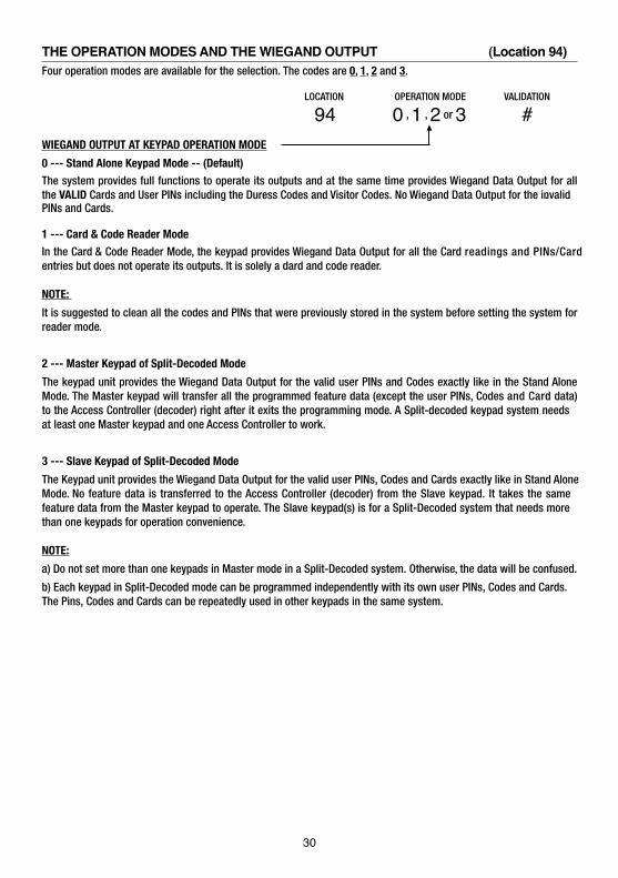
THE OPERATION MODES AND THE WIEGAND OUTPUT (Location 94) Four operation modes are available for the selection. The codes are 0, 1, 2 and 3.
WIEGAND OUTPUT AT KEYPAD OPERATION MODE
0 --- Stand Alone Keypad Mode -- (Default)The system provides full functions to operate its outputs and at the same time provides Wiegand Data Output for all the PINs and Cards.
VALID Cards and User PINs including the Duress Codes and Visitor Codes. No Wiegand Data Output for the invalid .
1 --- Card & Code Reader ModeIn the Card & Code Reader Mode, the keypad provides Wiegand Data Output for all the Card readings and PINs/Card entries but does not operate its outputs. It is solely a dard and code reader.
NOTE:
It is suggested to clean all the codes and PINs that were previously stored in the system before setting the system for reader mode.
2 --- Master Keypad of Split-Decoded Mode
The keypad unit provides the Wiegand Data Output for the valid user PINs and Codes exactly like in the Stand Alone Mode. The Master keypad will transfer all the programmed feature data (except the user PINs, Codes and Card data) to the Access Controller (decoder) right after it exits the programming mode. A Split-decoded keypad system needs at least one Master keypad and one Access Controller to work.
3 --- Slave Keypad of Split-Decoded Mode
The Keypad unit provides the Wiegand Data Output for the valid user PINs, Codes and Cards exactly like in Stand Alone Mode. No feature data is transferred to the Access Controller (decoder) from the Slave keypad. It takes the samefeature data from the Master keypad to operate. The Slave keypad(s) is for a Split-Decoded system that needs morethan one keypads for operation convenience.
NOTE:
a) Do not set more than one keypads in Master mode in a Split-Decoded system. Otherwise, the data will be confused.
b) Each keypad in Split-Decoded mode can be programmed independently with its own user PINs, Codes and Cards. The Pins, Codes and Cards can be repeatedly used in other keypads in the same system.
OPERATION MODELOCATION VALIDATION
#0 , 1 , 2 or 394
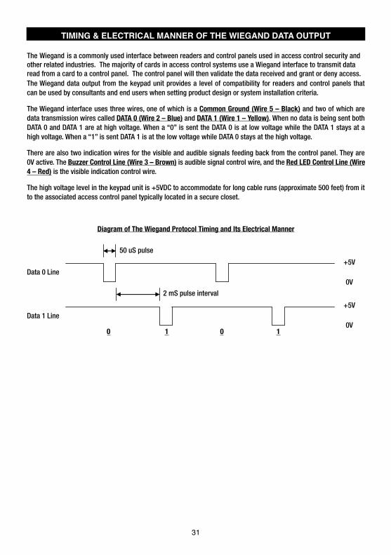
TIMING & ELECTRICAL MANNER OF THE WIEGAND DATA OUTPUT
The Wiegand data output from the keypad unit provides a level of compatibility for readers and control panels that
The Wiegand is a commonly used interface between readers and control panels used in access control security andother related industries. The majority of cards in access control systems use a Wiegand interface to transmit dataread from a card to a control panel. The control panel will then validate the data received and grant or deny access.
can be used by consultants and end users when setting product design or system installation criteria.
The Wiegand interface uses three wires, one of which is a Common Ground (Wire 5 – Black) and two of which are data transmission wires called DATA 0 (Wire 2 – Blue) and DATA 1 (Wire 1 – Yellow). When no data is being sent both DATA 0 and DATA 1 are at high voltage. When a “0” is sent the DATA 0 is at low voltage while the DATA 1 stays at a high voltage. When a “1” is sent DATA 1 is at the low voltage while DATA 0 stays at the high voltage.
There are also two indication wires for the visible and audible signals feeding back from the control panel. They are 0V active. The Buzzer Control Line (Wire 3 – Brown) is audible signal control wire, and the Red LED Control Line (Wire 4 – Red) is the visible indication control wire.
The high voltage level in the keypad unit is +5VDC to accommodate for long cable runs (approximate 500 feet) from it to the associated access control panel typically located in a secure closet.
Diagram of The Wiegand Protocol Timing and Its Electrical Manner
50 uS pulse
Data 0 Line
2 mS pulse interval
Data 1 Line
0 1 0 1
+5V
0V
+5V
0V
31

THE 26 BIT WIEGAND DATA OUTPUT FROM THE EM CARDS
Even paritythe trailing parity bit is an Odd parity bit from the last 12 bits. The data transmitted is in Binary codes for the Card reading.
Example 1: Wiegand Output of Reading An EM CardEach EM card or Keyfob is marked with an unique ID in Decimal Digits that is the code read by the reader. The EM card is also marked with a “3 digit+5 digit” code that does not belong to this system and can be ignored.
a) The Code Marked on One of The EM Cards :
The ID Code to be read for Wiegand Output The Code does not belong to this system
The Code in Decimal Number : 6 6 1 3 7 7 9The Code 6 6 1 3 7 7 9 Equivalent to Hex Number : 6 4 E B 1 3
b) Each Hex Number Consists of 4 Bits, Total 26 Bits of Wiegand Data Output from Card Reading:
E 6 4 E B 1 3 O
An Even Parity Bit of 6 4 E = 0 An Odd Parity Bit of B 1 3 = 1
c) The 26 bits Wiegand data sending out in Binary after reading of the card:
0 0 1 1 0 0 1 0 0 1 1 1 0 1 0 1 1 0 0 0 1 0 0 1 1 1
NOTE:
considered of reading a Card. The keypad provides Wiegand Data output for the Card only and the User PINs attached are NOT taken into account for the Wiegand output.
0006613779 008,18789
32
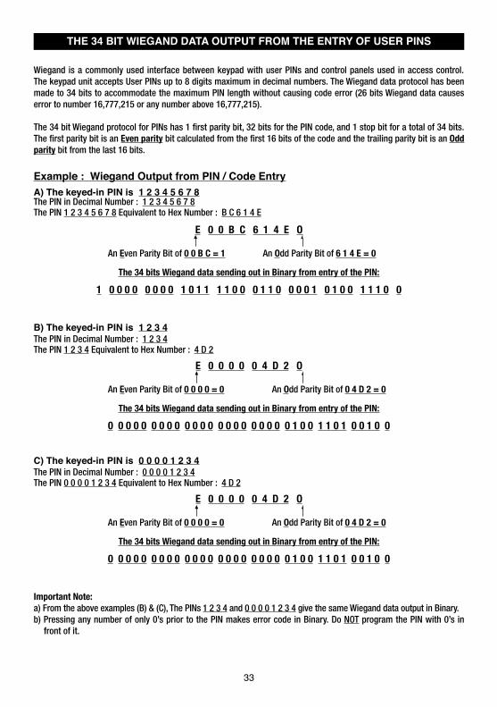
THE 34 BIT WIEGAND DATA OUTPUT FROM THE ENTRY OF USER PINS
Wiegand is a commonly used interface between keypad with user PINs and control panels used in access control. The keypad unit accepts User PINs up to 8 digits maximum in decimal numbers. The Wiegand data protocol has been made to 34 bits to accommodate the maximum PIN length without causing code error (26 bits Wiegand data causes error to number 16,777,215 or any number above 16,777,215).
The 34 bit Wiegand protocol for PINs has 1 first parity bit, 32 bits for the PIN code, and 1 stop bit for a total of 34 bits. The first parity bit is an Even parity bit calculated from the first 16 bits of the code and the trailing parity bit is an Odd parity bit from the last 16 bits.
Example : Wiegand Output from PIN / Code EntryA) The keyed-in PIN is 1 2 3 4 5 6 7 8The PIN in Decimal Number : 1 2 3 4 5 6 7 8The PIN 1 2 3 4 5 6 7 8 Equivalent to Hex Number : B C 6 1 4 E
E 0 0 B C 6 1 4 E O
An Even Parity Bit of 0 0 B C = 1 An Odd Parity Bit of 6 1 4 E = 0
The 34 bits Wiegand data sending out in Binary from entry of the PIN:
1 0 0 0 0 0 0 0 0 1 0 1 1 1 1 0 0 0 1 1 0 0 0 0 1 0 1 0 0 1 1 1 0 0
B) The keyed-in PIN is 1 2 3 4The PIN in Decimal Number : 1 2 3 4The PIN 1 2 3 4 Equivalent to Hex Number : 4 D 2
E 0 0 0 0 0 4 D 2 O
An Even Parity Bit of 0 0 0 0 = 0 An Odd Parity Bit of 0 4 D 2 = 0
The 34 bits Wiegand data sending out in Binary from entry of the PIN:
0 0 0 0 0 0 0 0 0 0 0 0 0 0 0 0 0 0 0 0 0 0 1 0 0 1 1 0 1 0 0 1 0 0
C) The keyed-in PIN is 0 0 0 0 1 2 3 4The PIN in Decimal Number : 0 0 0 0 1 2 3 4The PIN 0 0 0 0 1 2 3 4 Equivalent to Hex Number : 4 D 2
E 0 0 0 0 0 4 D 2 O
An Even Parity Bit of 0 0 0 0 = 0 An Odd Parity Bit of 0 4 D 2 = 0
The 34 bits Wiegand data sending out in Binary from entry of the PIN:
0 0 0 0 0 0 0 0 0 0 0 0 0 0 0 0 0 0 0 0 0 0 1 0 0 1 1 0 1 0 0 1 0 0
Important Note:a) From the above examples (B) & (C), The PINs 1 2 3 4 and 0 0 0 0 1 2 3 4 give the same Wiegand data output in Binary.b) Pressing any number of only 0’s prior to the PIN makes error code in Binary. Do NOT program the PIN with 0’s in
front of it.
33
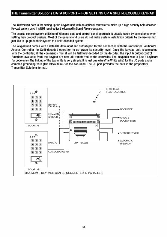
THE Transmitter Solutions DATA I/O PORT -- FOR SETTING UP A SPLIT-DECODED KEYPAD KEYPAD
The information here is for setting up the keypad unit with an optional controller to make up a high security Split-decoded Keypad system only. It is NOT required for the keypad in Stand Alone operation.
The access control system utilizing of Wiegand data and control panel approach is usually taken by consultants when setting their product designs. Most of the general end users do not make system installation criteria by themselves but just like to up grade their system to a split-decoded system.
The keypad unit comes with a data I/O (data input and output) port for the connection with the Transmitter Solutions’s Access Controller for Split-decoded operation to up-grade its security level. Once the keypad unit is connected with the controller, all the commands from it will be faithfully decoded by the decoder. The input & output control functions available from the keypad are now all transferred to the controller. The keypad’s role is just a keyboard for code entry. The link up of the two units is very simple. It is just one wire (The White Wire) for the I/O ports and a common grounding wire (The Black Wire) for the two units. The I/O port provides the data in the proprietary Transmitter Solutions format.
34
RF WIRELESSREMOTE CONTROL
DOOR LOCK
GARAGEDOOR OPENER
SECURITY SYSTEM
AUTOMATICOPERATOR
COMMON GROUND
COMMON GROUND
CONTROLLER
DOLXP1KB
DOLXP1KB
DATA I/O
DATA I/O
EXIT
MAXIMUM 3 KEYPADS CAN BE CONNECTED IN PARALLES

PROGRAMMING SUMMARY CHART
LOCATION FUNCTIONENTRY LIMITS & CODE
OPTIONS CODE ENTRY FACTORY DEFAULT
0 1 Master Code 4-8 Digits 01 MASTER CODE # NIL
0 2 Super User PIN 4-8 Digits 02 SUPER USER PIN # NIL
0 3 Common User PIN for O/P 1
4-8 Digits
03 COMMON USER PIN 1 # NIL
0 4 Common User PIN for O/P 2 04 NIL
0 5 Common User PIN for O/P 3 05 NIL
1 0 User PINs/Cards for O/P 1CODE 1 - RECORD/DELETE:1--- EM Card2--- Private User PIN3--- EM Card+Sec User PIN4--- EM Card+COM User PIN5--- Deletion of User PIN
CODE 2 - USER ID:000-999---Group 1(10)001-100---Group 2(20)001-100---Group 3(30)
CODE 3 - USER PINs:4-8 Digits/Cards
10 CODE1 CODE2 CODE3 # NIL
2 0 User PINs/Cards for O/P 2 20 CODE1 CODE2 CODE3 # NIL
3 0 User PINs/Cards for O/P 3 30 CODE1 CODE2 CODE3 # NIL
4 0 Visitor Codes
CODE 1 - VISITOR ID: 01-50
CODE 2 - VALID PERIOD: 00---One Time01-99 Hours
CODE 3 - VISITOR CODE: 4-8 Digits
40 CODE1 CODE2 CODE3 # NIL
4 1 Duress Code for O/P 1 CODE ID - O/P 1: 01-50
CODE ID - O/P 2: 01-10
CODE ID - O/P 3: 01-10
DURESS CODE: 4-8 Digits
41 CODE ID DURESS CODE # NIL
4 2 Duress Code for O/P 2 42 CODE ID DURESS CODE # NIL
4 3 Duress Code for O/P 3 43 CODE ID DURESS CODE # NIL
5 1 O/P Mode for O/P 1OUTPUT MODE & TIME:0--- Start / Stop1---99999 Seconds, Momentary
51 O/P MODE & TIME # 5 Seconds
5 2 O/P Mode for O/P 2 52 O/P MODE & TIME # 5 Seconds
5 3 O/P Mode for O/P 3 53 O/P MODE & TIME # 5 Seconds
6 0 Personal Safety & Lock-out
LOCK-OUT CODE:1---10 Trial, Lock-out 60 Sec.2---10 Trial, Activates Duress5-10---5-10 Trial, Lock-Out 15 Minutes00---No Lock-out
60 LOCK-OUT CODE #
Code = 1, 10 Trials, Lock-out 60 Seconds
7 0 PIN Entry ModeENTRY MODE:1---Auto Mode2---Manual Mode
70 ENTRY MODE #Mode = 2, Manual Mode
7 1 Pacifier Tone ON-OFF
FUNCTION MODE:0---OFF1---ON
71 FUNCTION MODE #Mode = 1, Pacifier Tone ON
7 2 Output Announcer 72 FUNCTION MODE #Mode = 1 Announcer ON
7 3 Standby LED Flashing 73 FUNCTION MODE #Mode = 1, Flashing On
COMMON USER PIN 2 #
COMMON USER PIN 3 #
35
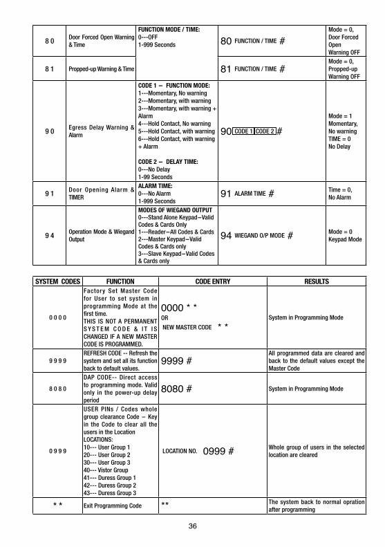
9 0 Egress Delay Warning & Alarm
CODE 1 - FUNCTION MODE:1---Momentary, No warning2---Momentary, with warning3---Momentary, with warning + Alarm4---Hold Contact, No warning5---Hold Contact, with warning6---Hold Contact, with warning + Alarm
CODE 2 - DELAY TIME: 0---No Delay1-99 Seconds
90 CODE 1 CODE 2 #Mode = 1 Momentary, No warningTIME = 0No Delay
9 1 Door Opening Alarm & TIMER
ALARM TIME:0---No Alarm1-999 Seconds
91 ALARM TIME # Time = 0, No Alarm
9 4 Operation Mode & Wiegand Output
MODES OF WIEGAND OUTPUT0---Stand Alone Keypad-Valid Codes & Cards Only1---Reader-All Codes & Cards2---Master Keypad-Valid Codes & Cards only3---Slave Keypad-Valid Codes & Cards only
94 WIEGAND O/P MODE # Mode = 0 Keypad Mode
SYSTEM CODES FUNCTION CODE ENTRY RESULTS
0 0 0 0
Factory Set Master Code for User to set system in programming Mode at the first time.THIS IS NOT A PERMANENT S Y S T E M C O D E & I T I S CHANGED IF A NEW MASTER CODE IS PROGRAMMED.
0000 * *OR
NEW MASTER CODE * *System in Programming Mode
9 9 9 9REFRESH CODE -- Refresh the system and set all its function back to default values.
9999 #All programmed data are cleared and back to the default values except the Master Code
8 0 8 0
DAP CODE-- Direct access to programming mode. Valid only in the power-up delay period
8080 # System in Programming Mode
0 9 9 9
USER PINs / Codes whole group clearance Code - Key in the Code to clear all the users in the LocationLOCATIONS:10--- User Group 120--- User Group 230--- User Group 340--- Vistor Group41--- Duress Group 142--- Duress Group 243--- Duress Group 3
LOCATION NO. 0999 # Whole group of users in the selected location are cleared
* * Exit Programming Code ** The system back to normal opration after programming
36
8 0 Door Forced Open Warning & Time
FUNCTION MODE / TIME:0---OFF1-999 Seconds 80 FUNCTION / TIME #
Mode = 0, Door Forced OpenWarning OFF
8 1 Propped-up Warning & Time 81 FUNCTION / TIME #Mode = 0, Propped-up Warning OFF

APPLICATION EXAMPLES 1) BASIC WIRINGS OF A STAND ALONE DOOR LOCK
NOTE:Connect the 1N4004 as close as possible to the lock in parallel with the lock power terminals of the lock to absorb the back EMF to prevent it from damaging the keypad. The 1N4004 is not required if the electric lock is AC operated.To avoid Electro-Static-Discharge from interfering with the operation of the keypad, always ground the (-) terminal of the keypad to earth.
Always connect DOOR SENSOR terminal to (-) ground if not used.
37
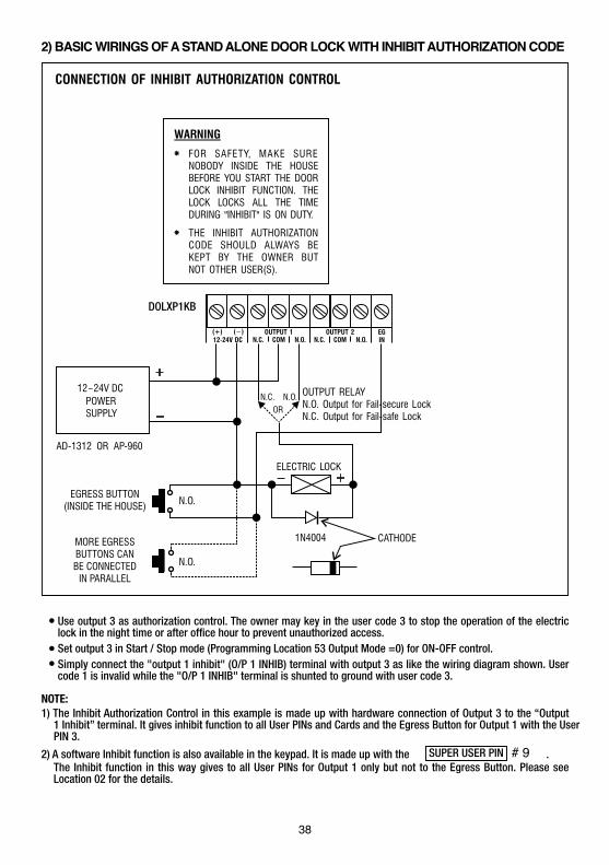
2) BASIC WIRINGS OF A STAND ALONE DOOR LOCK WITH INHIBIT AUTHORIZATION CODE
Use output 3 as authorization control. The owner may key in the user code 3 to stop the operation of the electric lock in the night time or after office hour to prevent unauthorized access.Set output 3 in Start / Stop mode (Programming Location 53 Output Mode =0) for ON-OFF control.Simply connect the "output 1 inhibit" (O/P 1 INHIB) terminal with output 3 as like the wiring diagram shown. User code 1 is invalid while the "O/P 1 INHIB" terminal is shunted to ground with user code 3.
NOTE:1) The Inhibit Authorization Control in this example is made up with hardware connection of Output 3 to the “Output
1 Inhibit” terminal. It gives inhibit function to all User PINs and Cards and the Egress Button for Output 1 with the User PIN 3.
2) A software Inhibit function is also available in the keypad. It is made up with the .The Inhibit function in this way gives to all User PINs for Output 1 only but not to the Egress Button. Please see Location 02 for the details.
SUPER USER PIN # 9
38
DOLXP1KB
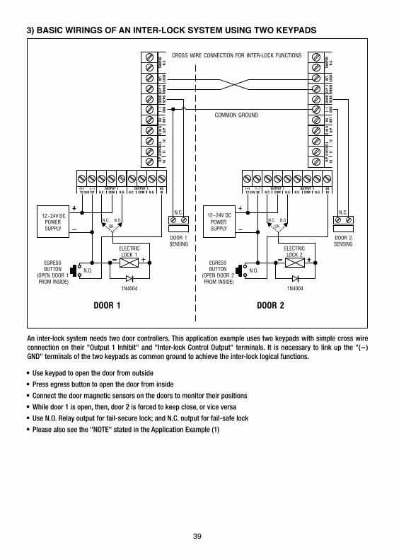
An inter-lock system needs two door controllers. This application example uses two keypads with simple cross wire connection on their "Output 1 Inhibit" and "Inter-lock Control Output" terminals. It is necessary to link up the "(-) GND" terminals of the two keypads as common ground to achieve the inter-lock logical functions.
Use keypad to open the door from outside
Press egress button to open the door from inside
Connect the door magnetic sensors on the doors to monitor their positions
While door 1 is open, then, door 2 is forced to keep close, or vice versa
Use N.O. Relay output for fail-secure lock; and N.C. output for fail-safe lock
Please also see the "NOTE" stated in the Application Example (1)
3) BASIC WIRINGS OF AN INTER-LOCK SYSTEM USING TWO KEYPADS
39
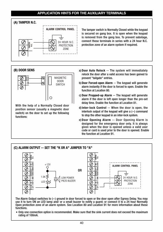
APPLICATION HINTS FOR THE AUXILIARY TERMINALS
The tamper switch is Normally Closed while the keypad is secured on gang box. It is open when the keypad is removed from the gang box. To prevent sabotage, connect these terminals in series with a 24 hour N.C. protection zone of an alarm system if required.
(A) TAMPER N.C.
40
With the help of a Normally Closed door position sensor (usually a magnetic door switch) on the door to set up the following functions:
Door Auto Relock -- The system will immediately relock the door after a valid access has been gained to prevent "tailgate" entries.
Door Forced-open Alarm -- The keypad will generate alarm instantly if the door is forced to open. Enable the function at Location 80.
Door Propped-up Alarm -- The keypad will generate alarm if the door is left open longer than the pre-set delay time. Enable the function at Location 81.
Inter-lock Control -- When the door is open, the interlock output of the keypad will give a (-) command to stop the other keypad in an inter-lock system.
Door Opening Alarm -- Door Opening Alarm is designed for the emergency door only. It is always given when the door is opened unless a valid user code or card is used prior to the door is opened. Enable the function at Location 91.
a)
b)
c)
d)
e)
(B) DOOR SENS
The Alarm Output switches to (-) ground in door forced to open or the door open after Egress Delay. You may use it to turn ON an LED lamp and/ or a small buzzer to notify a guard; or connect it to a 24 hour Normally Open protection zone of an alarm system. See Location 80 and Location 91 for more information about these functions.
Only one connection option is recommended. Make sure that the sink current does not exceed the maximum rating of 100mA.
(C) ALARM OUTPUT -- SET THE "K OR A" JUMPER TO "A"
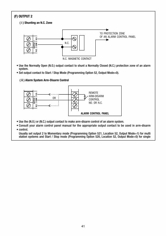
Use the Normally Open (N.O.) output contact to shunt a Normally Closed (N.C.) protection zone of an alarm system.Set output contact to Start / Stop Mode (Programming Option 52, Output Mode=0).
Use the (N.O.) or (N.C.) output contact to make arm-disarm control of an alarm system.Consult your alarm control panel manual for the appropriate output contact to be used in arm-disarm control.Usually set output 2 to Momentary mode (Programming Option 521, Location 52, Output Mode=1) for multi station systems and Start / Stop mode (Programming Option 520, Location 52, Output Mode=0) for single
(F) OUTPUT 2
( i ) Shunting an N.C. Zone
( ii ) Alarm System Arm-Disarm Control
41

APPENDIXDRY CONTACTA dry contact means that no electricity is connected to it. It is prepared for free connections. The Relay Output contacts provided in this keypad system are dry contacts.
N.C.Normally Closed, the contact is closed circuit at normal status. It is open circuit when active.
N.O.Normally Open, the contact is open circuit at normal status. It is closed circuit when active.
TRANSISTOR OPEN COLLECTOR OUTPUTAn open collector output is equivalent to a Normally Open (N.O.) contact referring to ground similar to a relay contact referring to ground. The transistor is normally OFF, and its output switches to ground (-) when active. The open collector can only provide switching function for small power but it is usually good enough for controlling of an alarm system. The Duress, Inter-lock and Key Active/Alarm Outputs of the keypad are open collector outputs.
OPEN COLLECTOROUTPUT ----Output switches toground when activated
N.O. CONTACTOUTPUT ----Output switches toground when activated
EQUIVALENT
42
7380 S. Eastern Avenue, Suite 124-320 Las Vegas, NV 89123
www.transmittersolutions.com