Embed Size (px)
Citation preview

VAMP 120
Arc protection unit
User manual

VM120.EN002_D

Table of Contents
VM120.EN002_D VAMP 24h support phone : +358 (0)20 753 3264 3
Table of contents
1. General ................................................................................... 4
1.1. Arc protection unit VAMP 120 ........................................... 4
1.2. Unit features ......................................................................... 4
2. Unit configuration ................................................................... 5
3. Sensors .................................................................................... 6
3.1. Arc sensor VA 1 DA ............................................................. 6
4. Functions ................................................................................. 8
5. Applications ............................................................................ 9
6. Connections ......................................................................... 10
7. Technical data ..................................................................... 11
Auxiliary voltage ................................................................. 11
Tripping contacts ............................................................... 11
BIO Input .............................................................................. 11
Disturbance tests ................................................................ 11
Voltage tests ....................................................................... 12
Mechanical tests ................................................................ 12
Environmental conditions ................................................. 12
8. Dimensions ............................................................................ 13
8.1. VAMP 120 .......................................................................... 13
8.2. VA 1 DA arc sensor .......................................................... 15
8.3. Mounting plates for VA 1 DA .......................................... 15
9. Order information ................................................................. 16
10. Reference information ......................................................... 17

1.1 Arc protection unit VAMP 120 1 General
4 VAMP 24h support phone : +358 (0)20 753 3264 VM120.EN002_D
1. General
This manual describes the general functions of the arc
protection unit, it also includes mounting and configuration
instructions.
1.1. Arc protection unit VAMP 120
Figure 1.1-1. Arc protection unit VAMP 120
1.2. Unit features
VAMP 120 is a state of the art arc protection unit for electrical
power distribution systems.
By using VAMP 120 in switchgears considerable safety
improvements are obtained in the form of minimized injury and
damage in case of an arc fault.
VAMP 120 is a “stand alone” system, which gives a compact
solution when the application doesn’t require overcurrent
measurement or when the overcurrent information is available
from the incomer protection relay or any other arc protection
unit (VAMP 221 / VAM 4C). It is possible to connect 4 arc
sensors, of the type VA 1 DA or VA 1 EH, to the VAMP 120
unit.

2 Unit configuration
VM120.EN002_D VAMP 24h support phone : +358 (0)20 753 3264 5
2. Unit configuration
Figure 2-1. VAMP 120 dipswitch operations and sensor connection
The unit is configured using the dipswitches:
Dipswitches 1-5 (see Figure 2-1):
If only one arc sensor in use, SENSOR 1 input should be used.
SW nr. 1 : if sensor input 2 is also required, SEN 1
should be set to the left position.
SW nr. 2 and 3 : if sensor input 3 and 4 are used, SW nr. 2
and 3 should respectively be set to left
position.
SW nr. 4 : is setting the system selectivity. If set to
the left position, sensor nr. 1 and 2 will
trip relay T1. Accordingly sensor nr. 3 and
4 will trip relay T2. The NC trip signal
out put will always work in parallel with
T1. If SW nr. 4 is to the right, all four
sensor channels will activate both trip
groups.
SW nr. 5 : is the selection of tripping criteria. If set
to the right, the unit will trip for light
only. If set to the left, the unit needs both
light and current information for tripping.
SW nr. 6 and 7 : the Latch switches enables latching of the
trip relays. When it is in ON position the
latching function is activated.
SW nr. 8 : is the configuration switch for sensor
inputs 2 and 3. If it is in “ON” position,
sensor 2 or 3 activation will make a
common trip of both T1 and T2. If it is in
“OFF” position, sensor 2 is linked to T1
and sensor 3 to T2.
3.1 Arc sensor VA 1 DA 3 Sensors
6 VAMP 24h support phone : +358 (0)20 753 3264 VM120.EN002_D
3. Sensors
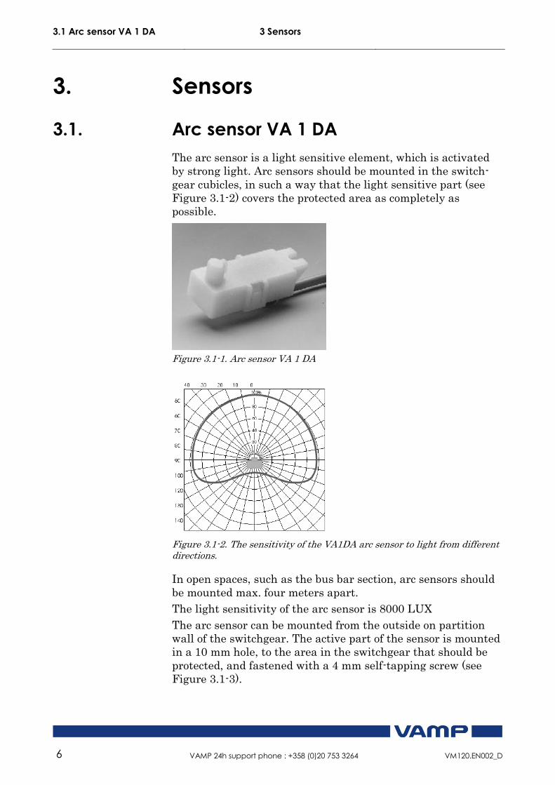
3.1. Arc sensor VA 1 DA
The arc sensor is a light sensitive element, which is activated
by strong light. Arc sensors should be mounted in the switch-
gear cubicles, in such a way that the light sensitive part (see
Figure 3.1-2) covers the protected area as completely as
possible.
Figure 3.1-1. Arc sensor VA 1 DA
Figure 3.1-2. The sensitivity of the VA1DA arc sensor to light from different directions.
In open spaces, such as the bus bar section, arc sensors should
be mounted max. four meters apart.
The light sensitivity of the arc sensor is 8000 LUX
The arc sensor can be mounted from the outside on partition
wall of the switchgear. The active part of the sensor is mounted
in a 10 mm hole, to the area in the switchgear that should be
protected, and fastened with a 4 mm self-tapping screw (see
Figure 3.1-3).

3 Sensors 3.1 Arc sensor VA 1 DA
VM120.EN002_D VAMP 24h support phone : +358 (0)20 753 3264 7
The arc sensor can alternatively be mounted completely in the
protected area with the help of a mounting plate VYX 01 (Z-
shaped) or VYX 02 (L-shaped). (See Figure 8.3-1)
Figure 3.1-3. Arc sensor mounting picture.

4 Functions
8 VAMP 24h support phone : +358 (0)20 753 3264 VM120.EN002_D
4. Functions
VAMP 120 includes an extensive self-supervision. The self-
supervision includes internal functions as well as all arc
sensors.
Figure 4-1 Self-supervision block diagram
If an internal fault occurs the self-supervision relay is activated
and the ERROR-led is lit.
5 Applications
VM120.EN002_D VAMP 24h support phone : +358 (0)20 753 3264 9
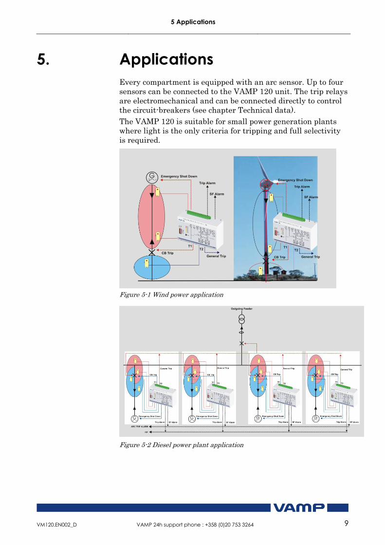
5. Applications
Every compartment is equipped with an arc sensor. Up to four
sensors can be connected to the VAMP 120 unit. The trip relays
are electromechanical and can be connected directly to control
the circuit-breakers (see chapter Technical data).
The VAMP 120 is suitable for small power generation plants
where light is the only criteria for tripping and full selectivity
is required.
Figure 5-1 Wind power application
Figure 5-2 Diesel power plant application

6 Connections
10 VAMP 24h support phone : +358 (0)20 753 3264 VM120.EN002_D
6. Connections
*Connection for shield if shield sensor cable used (VA1DA-20s)
Figure 6-1. VAMP 120 connection
The VAMP 120 unit comprises two independent arc protection
zones. Both zones have their own trip relay, trip 1 and trip 2.
Trip 1 is controlled by sensor inputs 1 and 2. Trip is controlled
by sensors 3 and 4.
Trip alarm is activated if either or both are tripping. If “T1=T2”
dip switch is at “on” position, both trip outputs will work in
parallel for any sensor activation.
If “S1=S2” dip switch is at “on” position, sensors 2 and 3
activation will cause both T1 and T2 to trip. This is e.g. used for
CB compartment supervision where two zones are overlapping
each other.
If overcurrent criteria is required simultaneously with light
activation, a binary current signal has to be connected to X2-
15/16. This I> signal can e.g. be taken from a VAM 4C or
VAMP 221 unit. The external reset is possible by correcting an
auxiliary voltage to X2-17/18.
The auxiliary boltage is connected to X2-1 and X2-2. VAMP has
a wide range power supply from 19 to 265 Vdc or 40 to 265 Vac
in the same hardware.

7 Technical data
VM120.EN002_D VAMP 24h support phone : +358 (0)20 753 3264 11
7. Technical data
Auxiliary voltage Us 19 … 265 V dc / 40 … 265 V ac
In (stby) 30mA
IsensAct 20mA
Iarc 120mA + (IsensAct x n);
n = number of active sensors
Tripping contacts Number 1
Rated voltage 250V ac/dc
Continuous carry 5A
Make and carry for 0.5s 30A
Make and carry for 3s 15A
Breaking capacity DC, when time
constant L/R=40ms
50W
Contact material AgCdO2
Operating time 7ms
BIO Input Rated voltage 18 - 265 Vac/dc
Rated current / input 5 mA
Number of inputs 2
Disturbance tests EMC test CE approved and designed according to EN
50081-2, EN 50082-2
Emission
- Conducted (EN 55011 class A) 0.15 - 30 MHz
- Emitted (EN 55011 class A) 30 - 1 000 MHz
Immunity
- Static discharge (ESD) (According to
IEC244-22-2 and EN61000-4-2, class III)
Air discharge 8 kV
Contact discharge 6 kV
- Fast transients (EFT) (According to
EN61000-4-4, class III and IEC801-4, level 4)
Power supply input 2kV, 5/50ns
other inputs 2 kV, 5/50ns
- Surge (According to EN61000-4-5 [09/96],
level 4)
Between wires 2 kV / 1.2/50µs
Between wire and earth 4 kV / 1.2/50µs
- RF electromagnetic field test (According. to
EN 61000-4-3, class III)
f = 80….1000 MHz 10V /m
- Conducted RF field (According. to EN 61000-
4-6, class III)
f = 150 kHz….80 MHz 10V

7 Technical data
12 VAMP 24h support phone : +358 (0)20 753 3264 VM120.EN002_D
Voltage tests Insulation test voltage acc- to IEC 60255-5 2 kV, 50Hz, 1min
Impulse test voltage acc- to IEC 60255-5 5 kV, 1.2/50us, 0.5J
Mechanical tests Vibration test 2 ... 13.2 Hz ±3.5mm
13.2 ... 100Hz, ±1.0g
Shock/Bump test acc. to IEC 60255-21-2 20g, 1000 bumps/dir.
Environmental conditions Specified ambient service temp. range -35…+70°C
Transport and storage temp. range -40…+70°C

8 Dimensions 8.1 VAMP 120
VM120.EN002_D VAMP 24h support phone : +358 (0)20 753 3264 13
8. Dimensions
8.1. VAMP 120

8.1 VAMP 120 8 Dimensions
14 VAMP 24h support phone : +358 (0)20 753 3264 VM120.EN002_D

8 Dimensions 8.2 VA 1 DA arc sensor
VM120.EN002_D VAMP 24h support phone : +358 (0)20 753 3264 15
8.2. VA 1 DA arc sensor
25
14
22
4
10
Figure 8.2-1. VA 1 DA arc sensor dimensions
8.3. Mounting plates for VA 1 DA
Figure 8.3-1. Mounting plate dimensions.

9 Order information
16 VAMP 24h support phone : +358 (0)20 753 3264 VM120.EN002_D
9. Order information
Unit Ordering code
VAMP 120 unit VAMP 120
Installation kit for flush mounting VYX 293A
Arc sensor, 6 m cable VA 1 DA-6
Arc sensor, 6 m cable VA 1 EH-6 (IP65)
Arc sensor, 20 m cable VA 1 DA-20

10 Reference information
VM120.EN002_D VAMP 24h support phone : +358 (0)20 753 3264 17
10. Reference information
Manufacturer data:
VAMP Ltd
P.O.Box 810
FIN-65101 Vaasa, Finland
Visiting address: Yrittäjänkatu 15
Phone: +358 (0)20 753 3200
Fax: +358 (0)20 753 3205
Service:
VAMP Ltd
P.O.Box 810
FIN-65101 Vaasa, Finland
Visiting address: Yrittäjänkatu 15
Phone: +358 (0)20 753 3200
Fax: +358 (0)20 753 3205
24h support phone:
Tel . +358 (0)20 753 3264
Email: [email protected]

10 Reference information
18 VAMP 24h support phone : +358 (0)20 753 3264 VM120.EN002_D

VM120.EN002_D

VM120.EN002_D
VAMP Ltd Street address: Yrittäjänkatu 15 Phone: +358 20 753 3200
Post address: Fax: +358 20 753 3205
Box 810, FIN 65101 Vaasa, Internet: www.vamp.fi
Finland Email: [email protected]
We reserve the rights to changes without prior notice


![VAMP 50 series - VAMP Japan [ Top ] · · 2010-02-054. VAMP 50 series protection relays. VAMPSET is a user-friendly, free-of-charge relay man-agement software for setting, parameterising](https://img.pdfslide.us/doc/110x75/5ae5d22e7f8b9aee078c1487/vamp-50-series-vamp-japan-top-vamp-50-series-protection-relays-vampset.jpg)