Embed Size (px)
Citation preview

VALX Airsuspension systemsWorkshop manual
Document code
Date
WSM_2052-01
March 2017
fdfMB MBS-V1

2 WSM_2052-01
For additional information on assembly, disassembly, adjustments, maintenance and repair, contact VALX B.V.:
De Amert 102, 5462 GH VeghelThe Netherlands
Tel: +31 (0)88-40 58 800 (general)
Tel: +31 (0)88-40 58 899 (breakdown number)
Fax: +31 (0)88-40 58 820
E-mail: [email protected] (general)E-mail: [email protected] (technicalsupport)
www.valx.eu
Document code: WSM 2052-01
Copyright © 2017
Revision summaryDate Revision number CommentMarch 2017 01 Initial version

WSM_2052-01 3
This document and all information herein is and remains at all times the exclusive property of VALX B.V. and shall not - in whole nor in part - without the prior written permission of VALX B.V. be disclosed to any other person, published in any form of publicity or news story, copied, photographed, reproduced or stored in any retrieval system of any nature.
The information in this document has been prepared solely for the purpose of providing information about assembly, disassembly, repair and maintenance on the trailer axle and the suspension system (hereafter: trailer axle). It has been compiled in good faith by VALX B.V. and is provided without any express or implied warranty as to its completeness or accuracy. We reserve the right to make amendments to this document to reflect further developments.
The original English text in this document will be legally binding and shall prevail in case of any variance between the English text and a translation. As any translation may be imprecise and inaccurate in whole or in part, VALX B.V. does not accept any risk, liability and responsibility for any translation.
Any quotations, offers and agreements relating to goods to be delivered and/or services to be provided by VALX B.V. shall always be subjected to VALX B.V.’s Terms of Sale and Delivery. All other terms and conditions are expressly rejected.
© 2017 VALX B.V. All rights reserved.

4 WSM_2052-01
Preface
Use of this manualThis Workshop Manual is intended for trained and qualified service technicians to enable them to perform all required maintenance and repair tasks on VALX products in an efficient, safe and environmentally sound way.
TAKE THE TIME TO READ THIS MANUAL THROUGHLY BEFORE PERFORMING ANY MAINTENANCE OR REPAIR TASK.
KEEP THIS MANUAL IN A SAFE PLACE, IN THE WORKSHOP.
THIS MANUAL REPLACES ALL PREVIOUS VERSIONS, IF ANY.
WSM_2052-01 5
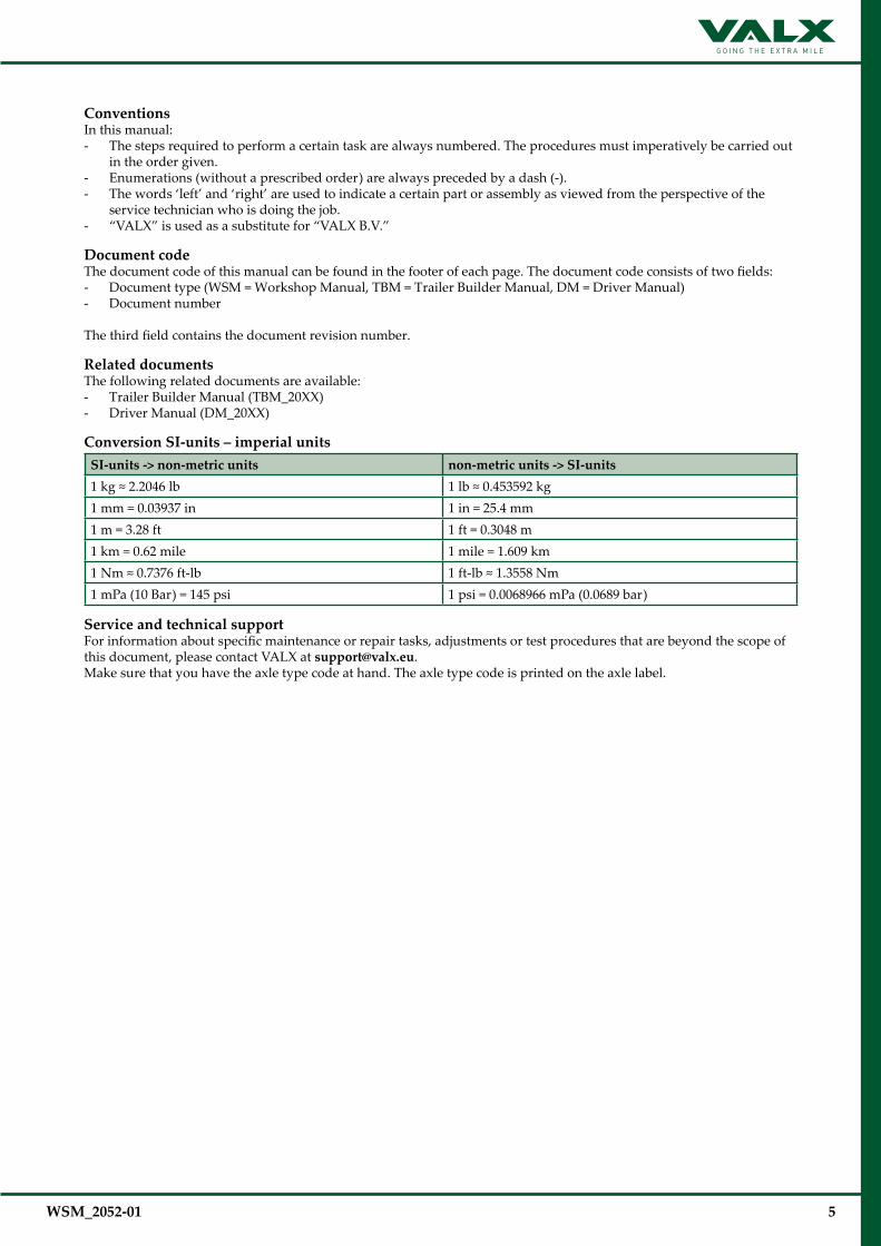
ConventionsIn this manual:- The steps required to perform a certain task are always numbered. The procedures must imperatively be carried out
in the order given.- Enumerations (without a prescribed order) are always preceded by a dash (-).- The words ‘left’ and ‘right’ are used to indicate a certain part or assembly as viewed from the perspective of the
service technician who is doing the job.- “VALX” is used as a substitute for “VALX B.V.”
Document codeThe document code of this manual can be found in the footer of each page. The document code consists of two fields:- Document type (WSM = Workshop Manual, TBM = Trailer Builder Manual, DM = Driver Manual)- Document number
The third field contains the document revision number.
Related documentsThe following related documents are available:- Trailer Builder Manual (TBM_20XX)- Driver Manual (DM_20XX)
Conversion SI-units – imperial unitsSI-units -> non-metric units non-metric units -> SI-units1 kg ≈ 2.2046 lb 1 lb ≈ 0.453592 kg1 mm = 0.03937 in 1 in = 25.4 mm1 m = 3.28 ft 1 ft = 0.3048 m1 km = 0.62 mile 1 mile = 1.609 km1 Nm ≈ 0.7376 ft-lb 1 ft-lb ≈ 1.3558 Nm1 mPa (10 Bar) = 145 psi 1 psi = 0.0068966 mPa (0.0689 bar)
Service and technical supportFor information about specific maintenance or repair tasks, adjustments or test procedures that are beyond the scope of this document, please contact VALX at [email protected]. Make sure that you have the axle type code at hand. The axle type code is printed on the axle label.

6 WSM_2052-01
TABLE OF CONTENTS
1 General safety instructions and regulations 7 1.1 General 7 1.2 This manual 7 1.3 Decals and instructions on the product 7 1.4 Warranty and original VALX parts 7 1.5 Maintenance and repair 7 1.6 A contribution to the protection of our environment 8
2 Air suspension system MBS-V1 9 2.1 Safety instructions 9 2.2 Overview 9 2.3 Periodic maintenance and inspection 10 2.4 Disassembly, assembly and adjustments 15 3 Air suspension system MBS-V2 22 3.1 Safety instructions 22 3.2 Overview 22 3.3 Code explanation 23 3.4 Offsetoverview 24 3.5 Periodic maintenance and inspection 25 3.6 Disassembly, assembly and adjustments 31
UNDER CONSTRUCTION
WSM_2052-01 7
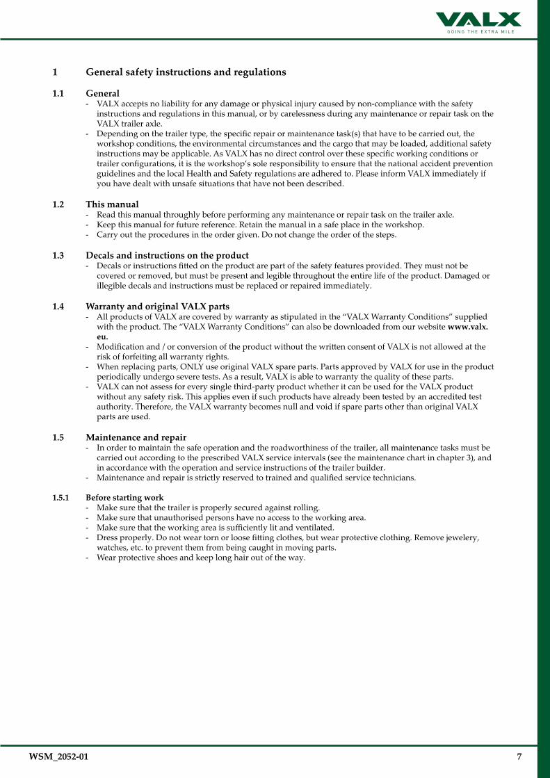
1 General safety instructions and regulations
1.1 General- VALX accepts no liability for any damage or physical injury caused by non-compliance with the safety
instructions and regulations in this manual, or by carelessness during any maintenance or repair task on the VALX trailer axle.
- Depending on the trailer type, the specific repair or maintenance task(s) that have to be carried out, the workshop conditions, the environmental circumstances and the cargo that may be loaded, additional safety instructions may be applicable. As VALX has no direct control over these specific working conditions or trailer configurations, it is the workshop’s sole responsibility to ensure that the national accident prevention guidelines and the local Health and Safety regulations are adhered to. Please inform VALX immediately if you have dealt with unsafe situations that have not been described.
1.2 This manual- Read this manual throughly before performing any maintenance or repair task on the trailer axle.- Keep this manual for future reference. Retain the manual in a safe place in the workshop.- Carry out the procedures in the order given. Do not change the order of the steps.
1.3 Decals and instructions on the product- Decals or instructions fitted on the product are part of the safety features provided. They must not be
covered or removed, but must be present and legible throughout the entire life of the product. Damaged or illegible decals and instructions must be replaced or repaired immediately.
1.4 Warranty and original VALX parts- All products of VALX are covered by warranty as stipulated in the “VALX Warranty Conditions” supplied
with the product. The “VALX Warranty Conditions” can also be downloaded from our website www.valx.eu.
- Modification and / or conversion of the product without the written consent of VALX is not allowed at the risk of forfeiting all warranty rights.
- When replacing parts, ONLY use original VALX spare parts. Parts approved by VALX for use in the product periodically undergo severe tests. As a result, VALX is able to warranty the quality of these parts.
- VALX can not assess for every single third-party product whether it can be used for the VALX product without any safety risk. This applies even if such products have already been tested by an accredited test authority. Therefore, the VALX warranty becomes null and void if spare parts other than original VALX parts are used.
1.5 Maintenance and repair- In order to maintain the safe operation and the roadworthiness of the trailer, all maintenance tasks must be
carried out according to the prescribed VALX service intervals (see the maintenance chart in chapter 3), and in accordance with the operation and service instructions of the trailer builder.
- Maintenance and repair is strictly reserved to trained and qualified service technicians. 1.5.1 Before starting work
- Make sure that the trailer is properly secured against rolling. - Make sure that unauthorised persons have no access to the working area.- Make sure that the working area is sufficiently lit and ventilated.- Dress properly. Do not wear torn or loose fitting clothes, but wear protective clothing. Remove jewelery,
watches, etc. to prevent them from being caught in moving parts.- Wear protective shoes and keep long hair out of the way.

8 WSM_2052-01
1.5.2 During work- Stay alert and watch what you are doing. Use common sense. Do not work on the product when you are
tired or have been taking alcohol, medicine or drugs. Do not smoke.- Use a hoist when lifting 25 kg or more. Only use suitable and technically perfect lifting devices with
adequate lifting capacity built in compliance with all safety measures. Fastening of loads and instructions to the operator of the lifting device are restricted to experienced personnel who are within sight or sound of the operator of the lifting device.
- Only use tools, parts, materials, lubricants and service techniques that were approved by VALX. Do not use contaminated or used lubricants. Used lubricants, cleansing agents and expended parts must be disposed of in an environmentally safe way.
- Avoid bodily contact with lubricants.- Never use worn tools and do not leave tools behind on the trailer axle or on the trailer.- Never weld on any part of the trailer axle or suspension without the prior written permission of VALX.- Never re-use self-locking fixing materials. Always replace them.
1.5.3 Whenworkisfinished- Inspect the product. Check for damage, leakage or defects. Any part removed for maintenance or repair
purposes must be refitted and checked immediately upon completion of the work.- Do not clear a product for operation unless it was established that it is absolutely safe and in perfect working
order.
1.6 A contribution to the protection of our environment Please obtain information about recycling or environmentally friendly processing of parts and materials that
have been replaced during maintenance or repair tasks. Almost all used lubricants are considered to be chemical waste. For the disposal of these a specialized company
must be contacted.
WSM_2052-01 9
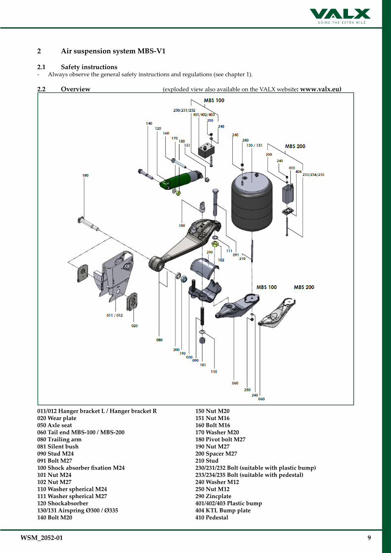
2 Air suspension system MBS-V1
2.1 Safety instructions - Always observe the general safety instructions and regulations (see chapter 1).
2.2 Overview (exploded view also available on the VALX website: www.valx.eu)
011/012 Hanger bracket L / Hanger bracket R020 Wear plate050 Axle seat060 Tail end MBS-100 / MBS-200080 Trailing arm 081 Silent bush090 Stud M24091 Bolt M27100ShockabsorberfixationM24101 Nut M24102 Nut M27110 Washer spherical M24111 Washer spherical M27120 Shockabsorber 130/131 Airspring Ø300 / Ø335140 Bolt M20
150 Nut M20151 Nut M16160 Bolt M16170 Washer M20180 Pivot bolt M27190 Nut M27200 Spacer M27210 Stud230/231/232 Bolt (suitable with plastic bump)233/234/235 Bolt (suitable with pedestal)240 Washer M12250 Nut M12290 Zincplate401/402/403 Plastic bump404 KTL Bump plate410 Pedestal
10 WSM_2052-01
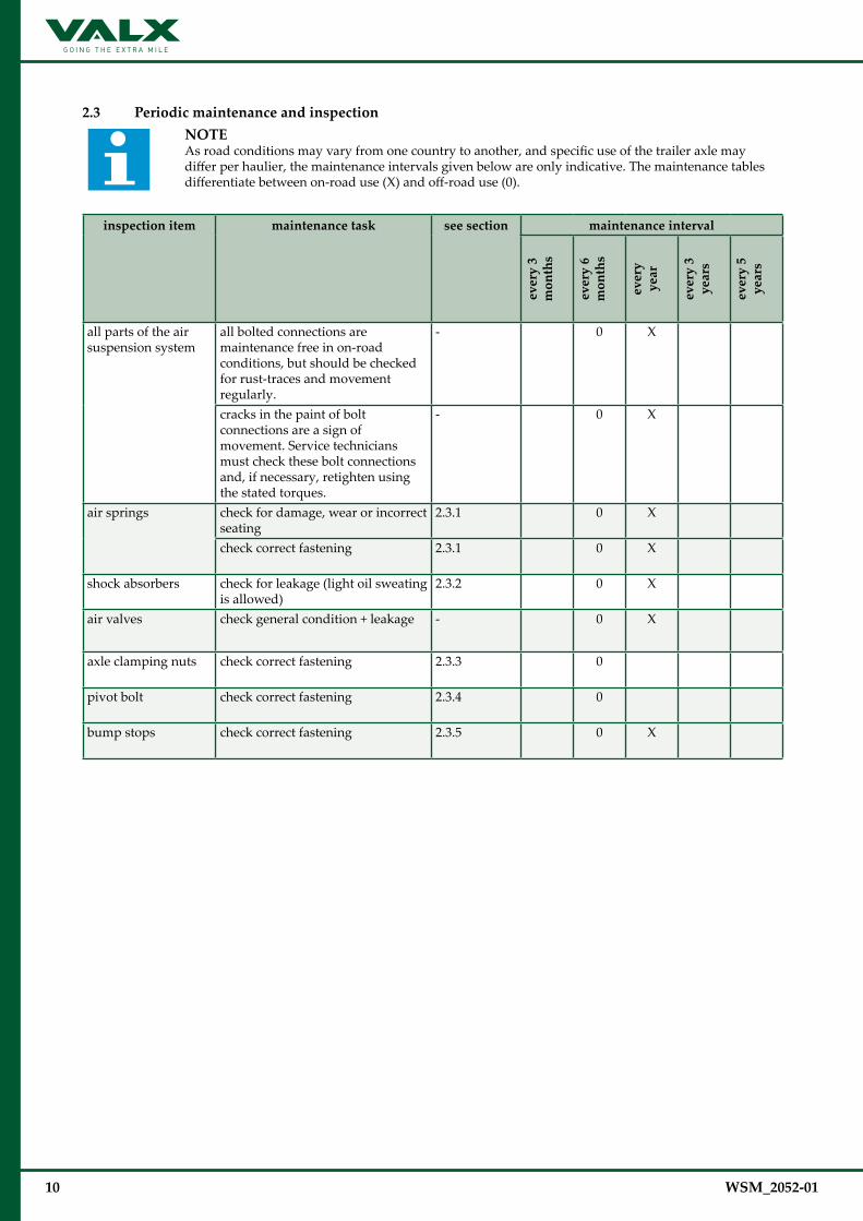
2.3 Periodic maintenance and inspectionNOTE As road conditions may vary from one country to another, and specific use of the trailer axle may differ per haulier, the maintenance intervals given below are only indicative. The maintenance tables differentiate between on-road use (X) and off-road use (0).
inspection item maintenance task see section maintenance interval
ever
y 3
m
onth
s
ever
y 6
m
onth
s
ever
y
year
ever
y 3
ye
ars
ever
y 5
ye
ars
all parts of the air suspension system
all bolted connections are maintenance free in on-road conditions, but should be checked for rust-traces and movement regularly.
- 0 X
cracks in the paint of bolt connections are a sign of movement. Service technicians must check these bolt connections and, if necessary, retighten using the stated torques.
- 0 X
air springs check for damage, wear or incorrect seating
2.3.1 0 X
check correct fastening 2.3.1 0 X
shock absorbers check for leakage (light oil sweating is allowed)
2.3.2 0 X
air valves check general condition + leakage - 0 X
axle clamping nuts check correct fastening 2.3.3 0
pivot bolt check correct fastening 2.3.4 0
bump stops check correct fastening 2.3.5 0 X
WSM_2052-01 11
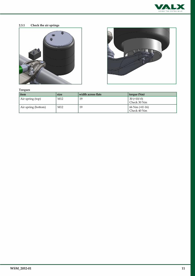
2.3.1 Check the air springs
Torques item size widthacrossflats torque (Nm) Air spring (top) M12 19 30 (+10/-0)
Check 30 NmAir spring (bottom) M12 19 66 Nm (+0/-16)
Check 40 Nm

12 WSM_2052-01
2.3.2 Check the shock absorbers and mounting
Light oil sweating is allowed. Oil leakage is not allowed.Ensure the nuts are facing outwardsMake sure the text “bottom” or “road” on the shockabsorbers is facing downTorque at ride height
Torques item size widthacrossflats torque (Nm) shock absorber (top) M20 24 & 30 550 Nm (+ 50 Nm - 0 Nm)
Check 450 Nmshock absorber (bottom) M16 24 170 Nm (+17/-0) + 270° (+17/-13)
Check 300 Nm
2.3.3 Check the axle clamping nuts
Torques item size widthacrossflats torque (Nm) axle clamping (front) M24 36 800 Nm (+50/0) 1,2
Check 650 Nmaxle clamping (rear) M27 41 950 Nm (+50/-0) 1,2
Check 750 Nm
1 When loosening the axle clamping, all fasteners need to be replaced!
2 First tighten the M24 connection of the axle claming, then tighten the M27 connection

WSM_2052-01 13
2.3.4 Check the pivot bolt
Torques item size widthacrossflats torque (Nm) pivot bolt M27 41 950 Nm (+50/0) + apply grease on min.
90° of the thread surface + ring 1Check 750 Nm
1 Grease specification: Lithium complex grease (class 2)
2.3.5 Check the bump stop
Torques item size widthacrossflats torque (Nm) Plastic bump fastening (MBS-100) M12 19 30 (+10/-0)
Check 30 NmSteel bump fastening (MBS-200) M12 19 66 (+0/-16)
Check 40 Nm
MBS100
MBS200
MBS200MBS100
14 WSM_2052-01
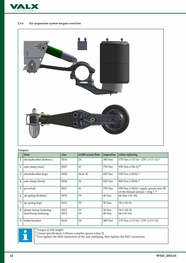
2.3.6 Air suspension system torques overview
Torques item size widthacrossflats inspection when replacing
1 shockabsorber (bottom ) M16 24 300 Nm 170 Nm (+17/-0) + 270° (+17/-13) 1
2 axle clamp (rear) M27 41 750 Nm 950 Nm (+50/-0) 3
3 shockabsorber (top) M20 24 & 30 450 Nm 550 Nm (+50/0) 1
4 axle clamp (front) M24 36 650 Nm 800 Nm (+50/0) 3
5 pivot bolt M27 41 750 Nm 950 Nm (+50/0) + apply grease min 90° of the thread surface + ring 1 ,2
6 air spring (bottom) M12 19 40 Nm 66 Nm (+0/-16)
7 air spring (top) M12 19 30 Nm 30 (+10/-0)
8 plastic bump fasteningsteel bump fastening
M12M12
1919
30 Nm40 Nm
30 (+10/-0)66 (+0/-16)
9 bolted bracket M16 24 300 Nm 170 Nm (+17/-0) + 270° (+17/-13)
1 Torque at ride height2 Grease specification: Lithium complex grease (class 2)3 First tighten the M24 connection of the axle clamping, then tighten the M27 connection
WSM_2052-01 15
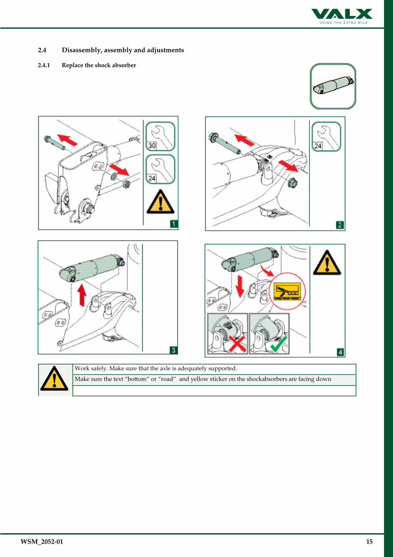
2.4 Disassembly, assembly and adjustments
2.4.1 Replace the shock absorber
Work safely. Make sure that the axle is adequately supported.
Make sure the text “bottom” or “road” and yellow sticker on the shockabsorbers are facing down

16 WSM_2052-01
2.4.1 Replace the shock absorber (continued)
Bolt shock absorber from inside to outside.
Check for correct torque, and use the correct hole for MBS-100 or MBS-200.
Torque bolt connections at ride height
Torques item size widthacrossflats torque (Nm) shockabsorber (top) M20 24 & 30 550 Nm (+ 50 Nm - 0 Nm)
Check 450 Nmshockabsorber (bottom) M16 24 170 Nm (+17/-0) + 270° (+17/-13)
Check 300 Nm

WSM_2052-01 17
2.4.2 Replace the air springs
Disconnect the air line before replacement.
Work safely. Make sure that the axle is adequately supported.
Make sure the treaded end is completely inserted into the air spring bottom piece.

18 WSM_2052-01
2.4.2 Replace the air springs (continued)
Make sure that the shape of the airspring is placed correctly on the tail end (step 5)
After replacement reconnect the air line.
Torques item size widthacrossflats torque (Nm)
air spring (bottom) M12 19 66 Nm (+0/-16) Check 40 Nm
air spring (top) M12 (2x) 19 30 Nm (+ 10/-0) Check 30 Nm

WSM_2052-01 19
2.4.3 Replace complete air suspension
Work safely. Make sure that the axle is adequately supported.
Bolt shock absorber from inside to outside.Make sure the text “bottom” or “road” and yellow sticker on the shockabsorbers are facing down
Torques item size widthacrossflats torque (Nm) shockabsorber (bottom) M16 24 170 Nm (+17/-0) + 270° (+17/-13)
Check 300 Nm

20 WSM_2052-01
2.4.3 Replace complete air suspension (continued)
Make sure that the axle seat is well placed in the axle groove
Make sure the zinc plate is well placed between the trailing arm and axle beamAlways tighten the M24 nuts before tightening nut M27Recheck the spring track
Torques item size widthacrossflats torque (Nm) axle clamp (front) M24 36 800 Nm (+50/-0)
Check 650 Nm
Check the correct tail end off set
Place the M27 bolt in the trailing arm with the flat faces (see bolt head) in the length of the trailing armMake sure the M24 connections are fully tightened before tightening the M27 connectionRecheck the tail end offset
Torques item size widthacrossflats torque (Nm) axle clamp (rear) M27 41 950 Nm (+50/-0)
Check 750 Nm

WSM_2052-01 21
2.4.4 Assemble the pivot bolt
Apply grease on min. 90° of the thread surface + ring
Grease specification: Lithium complex grease (class 2).Before tightening to end torque, make sure the trailer is at correct driving height
Torques item size widthacrossflats torque (Nm) Pivot bolt M27 41 950 Nm (+50/-0)
Check 750 Nm
22 WSM_2052-01
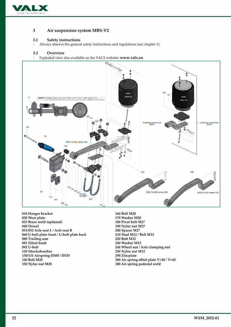
3 Air suspension system MBS-V2
3.1 Safety instructions - Always observe the general safety instructions and regulations (see chapter 1).
3.2 Overview - Exploded view also available on the VALX website: www.valx.eu
010 Hanger bracket 020 Wear plate023 Brace weld (optional)040 Dowel051/052 Axle seat L / Axle seat R060 U-bolt plate front / U-bolt plate back080 Trailing arm 081 Silent bush092 U-bolt120 Shockabsorber 130/131 Airspring Ø300 / Ø335140 Bolt M20150 Nyloc nut M20
160 Bolt M20170 Washer M20180 Pivot bolt M27190 Nyloc nut M27200 Spacer M27210 Stud M12 / Bolt M12220 Bolt M12240 Washer M12244 Wheel nut / Axle clamping nut250 Nyloc nut M12290 Zincplate300AirspringoffsetplateV=20/V=45380 Air spring pedestal weld
WSM_2052-01 23
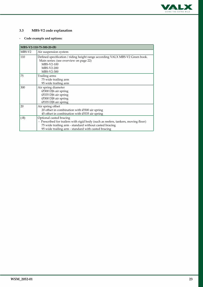
3.3 MBS-V2 code explanation
- Code example and options:
MBS-V2-110-75-300-20-(B)MBS-V2 Air suspension system110 Defined specification / riding height range according VALX MBS-V2 Green book.
Main series: (see overview on page 22) MBS-V2-100 MBS-V2-200 MBS-V2-300
75 Trailing arms 75 wide trailing arm 95 wide trailing arm
300 Air spring diameter Ø300 DJ6 air spring Ø335 DJ6 air spring Ø300 DJ8 air spring Ø335 DJ8 air spring
20 Air spring offset 20 offset in combination with Ø300 air spring 45 offset in combination with Ø335 air spring
(-B) Optional casted bracing - Prescribed for trailers with rigid body (such as reefers, tankers, moving floor) 75 wide trailing arm - standard without casted bracing 95 wide trailing arm - standard with casted bracing
24 WSM_2052-01
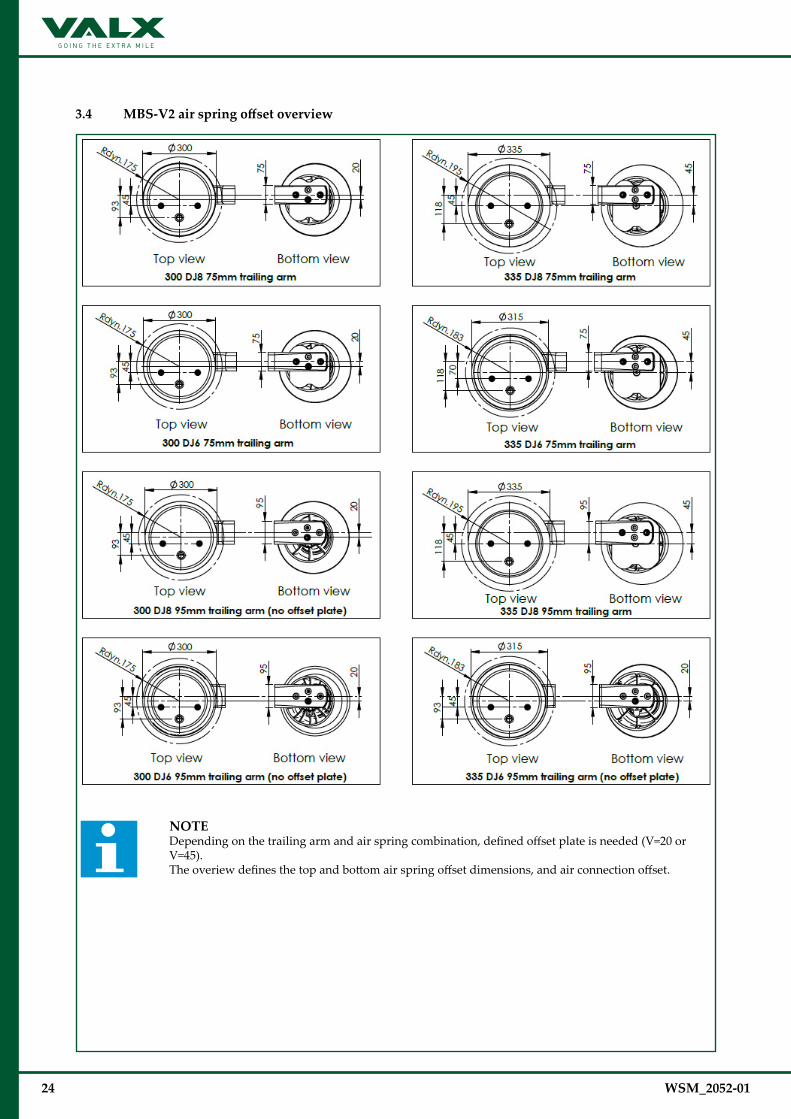
3.4 MBS-V2airspringoffsetoverview
NOTE Depending on the trailing arm and air spring combination, defined offset plate is needed (V=20 or V=45). The overiew defines the top and bottom air spring offset dimensions, and air connection offset.

WSM_2052-01 25
3.5 Periodic maintenance and inspection
NOTE As road conditions may vary from one country to another, and specific use of the trailer axle may differ per haulier, the maintenance intervals given below are only indicative. The maintenance tables differentiate between on-road use (X) and off-road use (0).
inspection item maintenance task see section maintenance interval
ever
y 3
m
onth
s
ever
y 6
m
onth
s
ever
y
year
ever
y 3
ye
ars
ever
y 5
ye
ars
all parts of the air suspension system
all bolted connections are maintenance free in on-road conditions, but should be checked for rust-traces and movement regularly.
- 0 X
cracks in the paint of bolt connections are a sign of movement. Service technicians must check these bolt connections and, if necessary, retighten using the stated torques.
- 0 X
air springs and offset plates
check for damage, wear or incorrect seating
3.5.1 0 X
check correct fastening 3.5.1 0 X
shock absorbers check for leakage (light oil sweating is allowed)
3.5.2 0 X
air valves check general condition + leakage - 0 X
axle clamping nuts check correct fastening 3.5.3 0
pivot bolt check correct fastening 3.5.4 0
26 WSM_2052-01
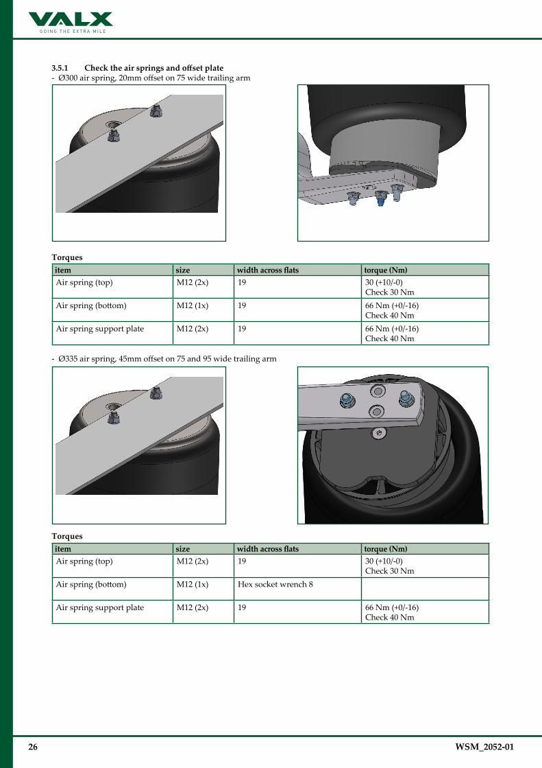
3.5.1 Checktheairspringsandoffsetplate- Ø300 air spring, 20mm offset on 75 wide trailing arm
Torques item size widthacrossflats torque (Nm) Air spring (top) M12 (2x) 19 30 (+10/-0)
Check 30 NmAir spring (bottom)
M12 (1x) 19 66 Nm (+0/-16)Check 40 Nm
Air spring support plate M12 (2x) 19 66 Nm (+0/-16)Check 40 Nm
- Ø335 air spring, 45mm offset on 75 and 95 wide trailing arm
Torques item size widthacrossflats torque (Nm) Air spring (top) M12 (2x) 19 30 (+10/-0)
Check 30 NmAir spring (bottom)
M12 (1x) Hex socket wrench 8
Air spring support plate M12 (2x) 19 66 Nm (+0/-16)Check 40 Nm
WSM_2052-01 27
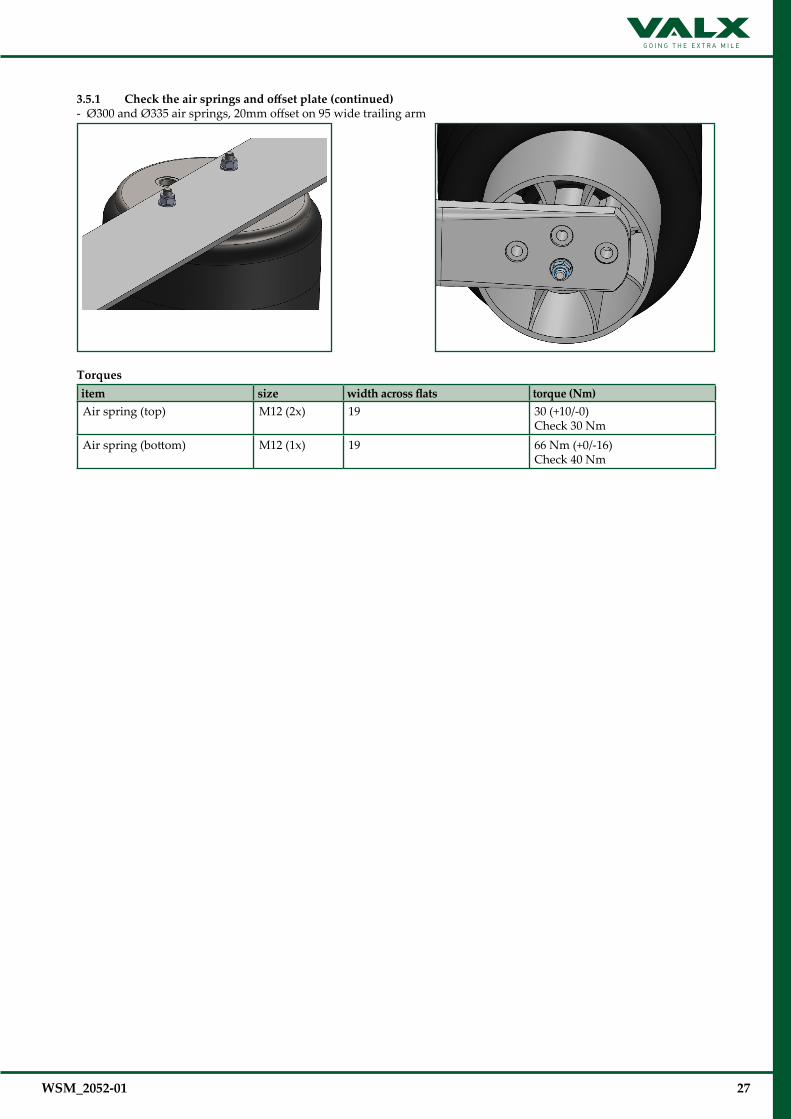
3.5.1 Checktheairspringsandoffsetplate(continued)- Ø300 and Ø335 air springs, 20mm offset on 95 wide trailing arm
Torques item size widthacrossflats torque (Nm) Air spring (top) M12 (2x) 19 30 (+10/-0)
Check 30 NmAir spring (bottom)
M12 (1x) 19 66 Nm (+0/-16)Check 40 Nm
28 WSM_2052-01
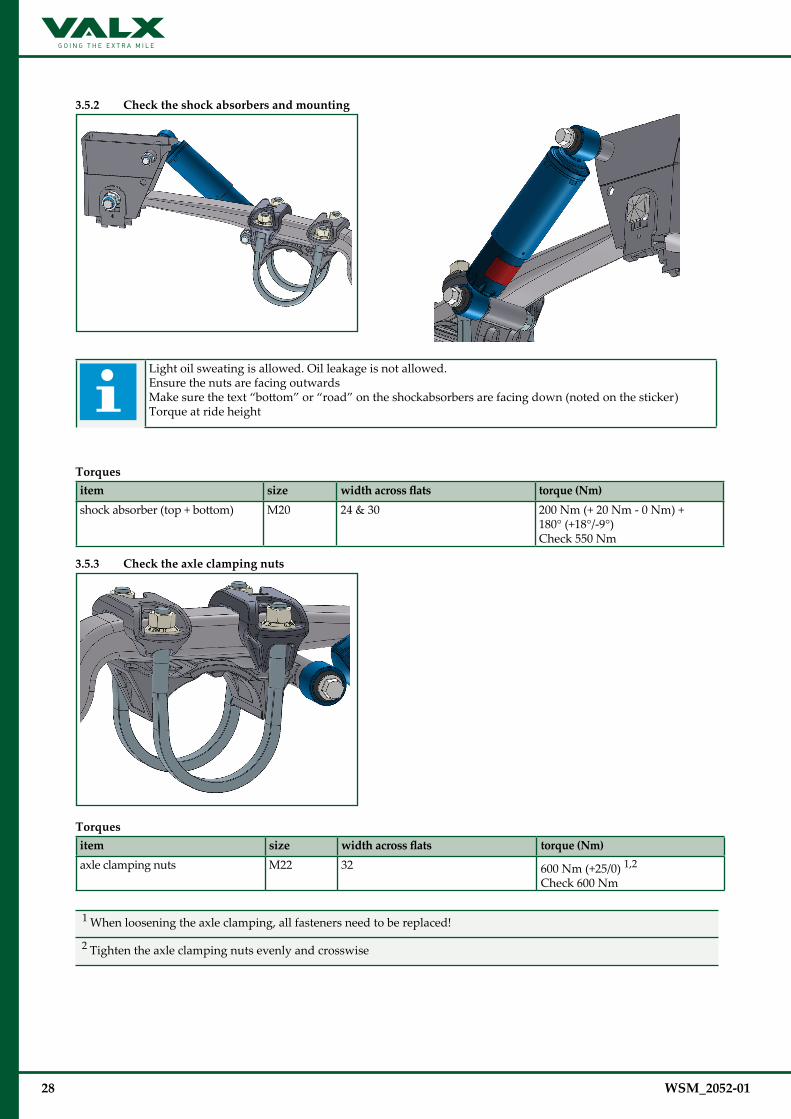
3.5.2 Check the shock absorbers and mounting
Light oil sweating is allowed. Oil leakage is not allowed.Ensure the nuts are facing outwardsMake sure the text “bottom” or “road” on the shockabsorbers are facing down (noted on the sticker)Torque at ride height
Torques item size widthacrossflats torque (Nm) shock absorber (top + bottom) M20 24 & 30 200 Nm (+ 20 Nm - 0 Nm) +
180° (+18°/-9°)Check 550 Nm
3.5.3 Check the axle clamping nuts
Torques item size widthacrossflats torque (Nm) axle clamping nuts M22 32 600 Nm (+25/0) 1,2
Check 600 Nm
1 When loosening the axle clamping, all fasteners need to be replaced!
2 Tighten the axle clamping nuts evenly and crosswise

WSM_2052-01 29
3.5.4 Check the pivot bolt
Torques item size widthacrossflats torque (Nm) pivot bolt M27 41 250 Nm (+25/0) + 250° (+27°/-13°)
+apply grease on min. 90° of the thread surface + ring 1Check 750 Nm
1 Grease specification: Lithium complex grease (class 2)

30 WSM_2052-01
3.5.5 Air suspension system torques overview
Torques item size widthacrossflats inspection when replacing
1 shockabsorber (top + bottom ) M20 24 & 30 550 Nm 200 Nm (+20/-0) + 180° (+18/-9) 1
2 axle clamp M22 32 600 Nm 600 Nm (+25/-0)
3 pivot bolt M27 41 750 Nm 250 Nm (+25/0) + 250° (+27°/-13°)+ apply grease on min. 90° of the thread surface + ring 1,2
4 air spring (bottom) M12 19 40 Nm 66 Nm (+0/-16)
5 air spring (top) M12 19 30 Nm 30 (+10/-0)
6 air spring support plate M12 19 40 Nm 66 (+0/-16)
7 axle lift M16 24 200 Nm 200 Nm (+/-20)
1 Torque at ride height2 Grease specification: Lithium complex grease (class 2)
WSM_2052-01 31
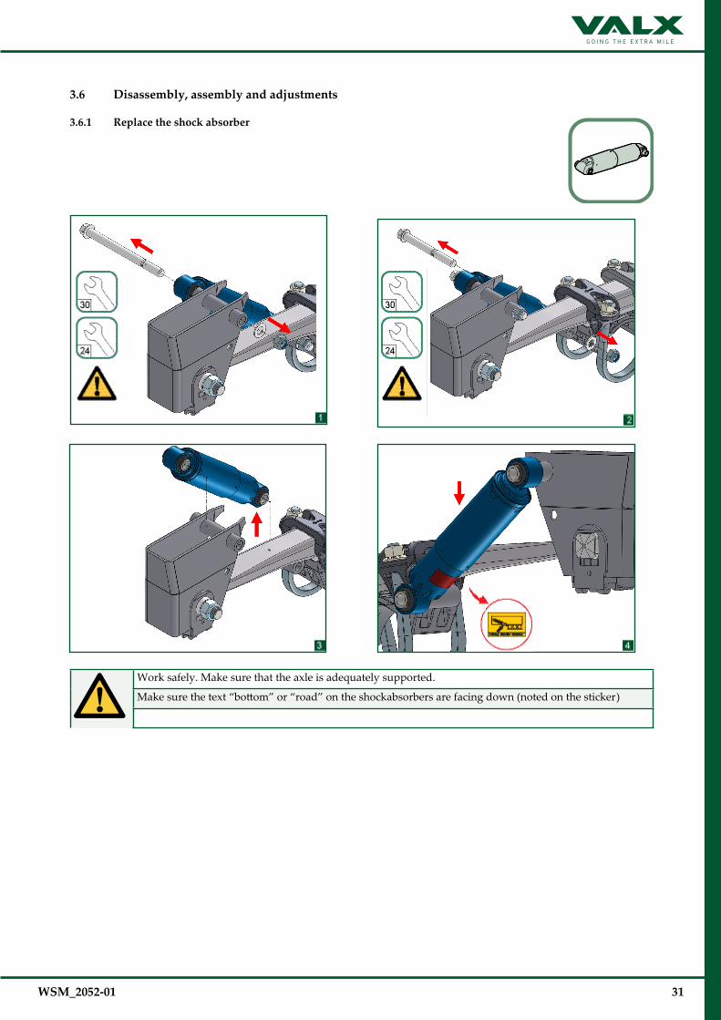
3.6 Disassembly, assembly and adjustments
3.6.1 Replace the shock absorber
Work safely. Make sure that the axle is adequately supported.
Make sure the text “bottom” or “road” on the shockabsorbers are facing down (noted on the sticker)
32 WSM_2052-01
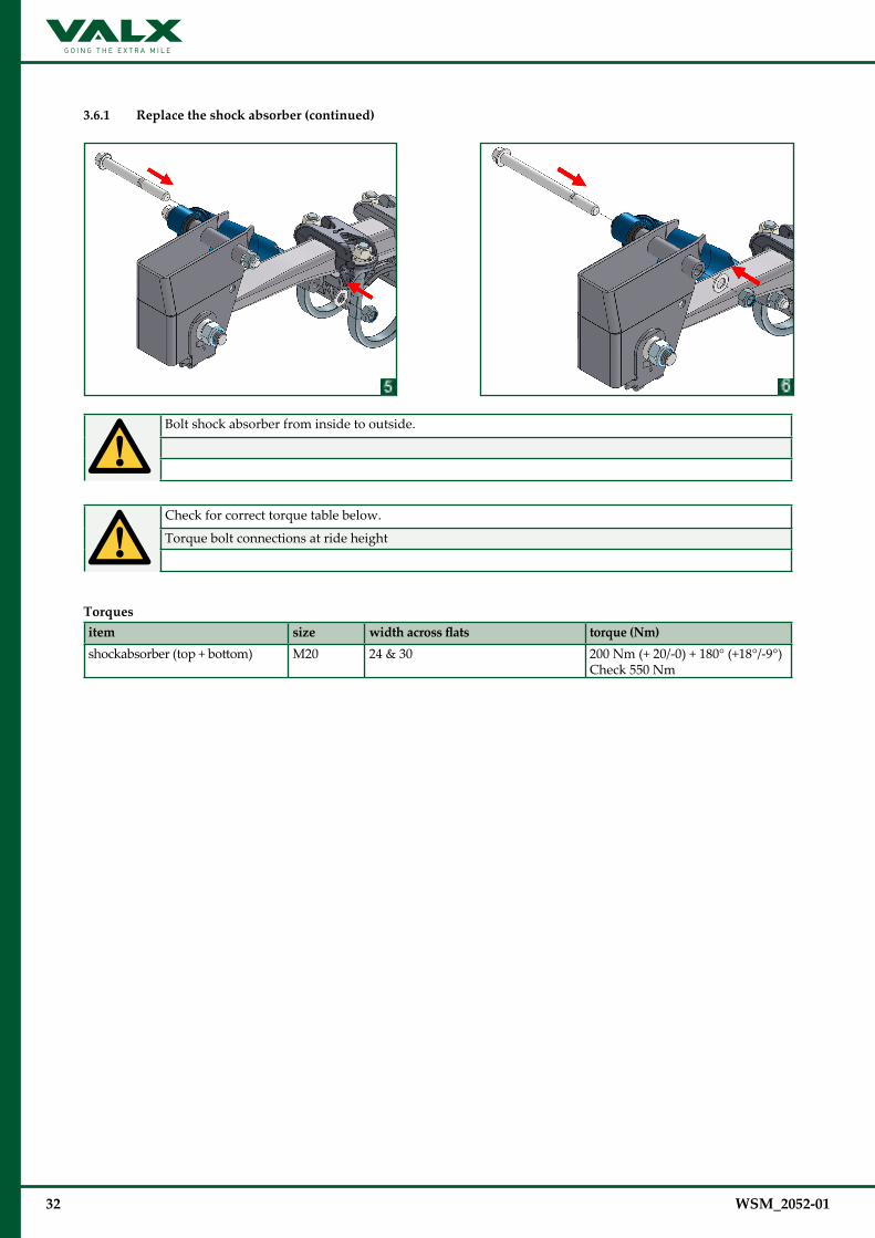
3.6.1 Replace the shock absorber (continued)
Bolt shock absorber from inside to outside.
Check for correct torque table below.
Torque bolt connections at ride height
Torques item size widthacrossflats torque (Nm) shockabsorber (top + bottom) M20 24 & 30 200 Nm (+ 20/-0) + 180° (+18°/-9°)
Check 550 Nm
WSM_2052-01 33
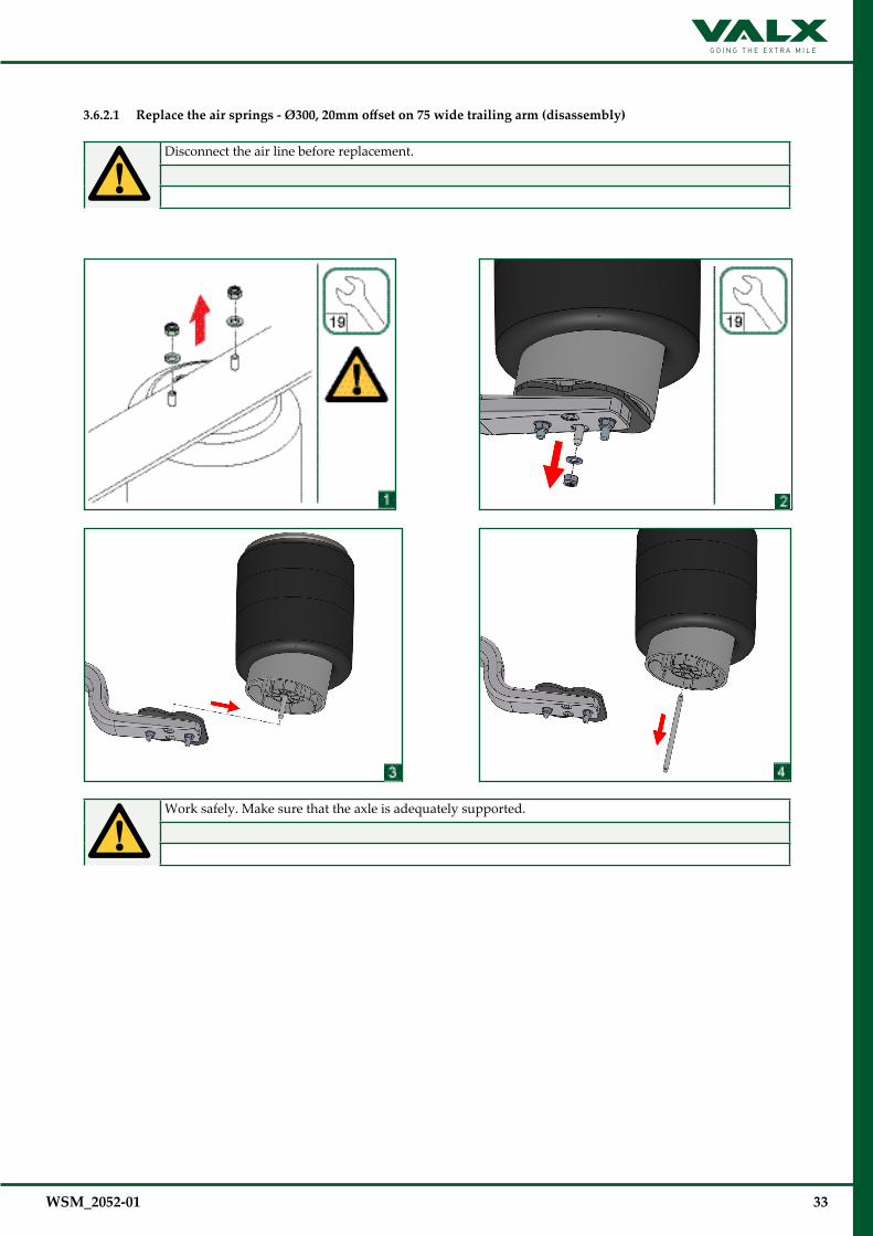
3.6.2.1 Replace the air springs - Ø300,20mmoffseton75widetrailingarm(disassembly)
Disconnect the air line before replacement.
Work safely. Make sure that the axle is adequately supported.
34 WSM_2052-01
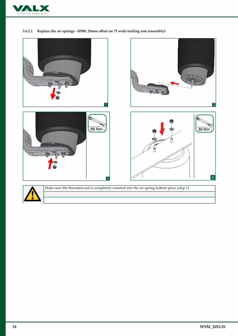
3.6.2.1 Replacetheairsprings-Ø300,20mmoffseton75widetrailingarm(assembly)
Make sure the threaded end is completely inserted into the air spring bottom piece (step 1)

WSM_2052-01 35
3.6.2.2 Replace the air springs - Ø335,45mmoffseton75and95widetrailingarm(disassembly)
Disconnect the air line before replacement.
Work safely. Make sure that the axle is adequately supported.
36 WSM_2052-01
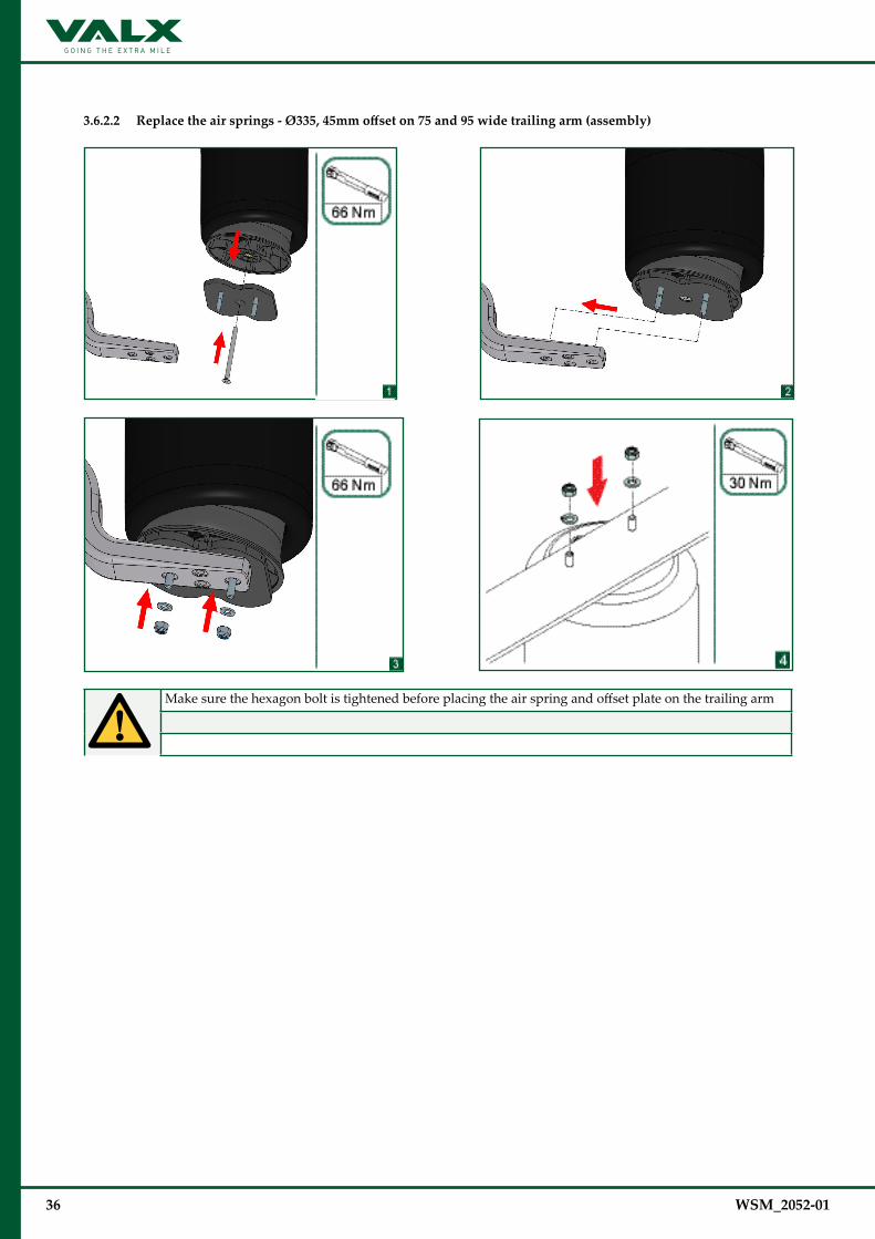
3.6.2.2 Replace the air springs - Ø335,45mmoffseton75and95widetrailingarm(assembly)
Make sure the hexagon bolt is tightened before placing the air spring and offset plate on the trailing arm

WSM_2052-01 37
3.6.2.3 Replace the air springs - Ø300 / Ø335,20mmoffseton95widetrailingarm(disassembly)
Disconnect the air line before replacement.
Work safely. Make sure that the axle is adequately supported.
38 WSM_2052-01
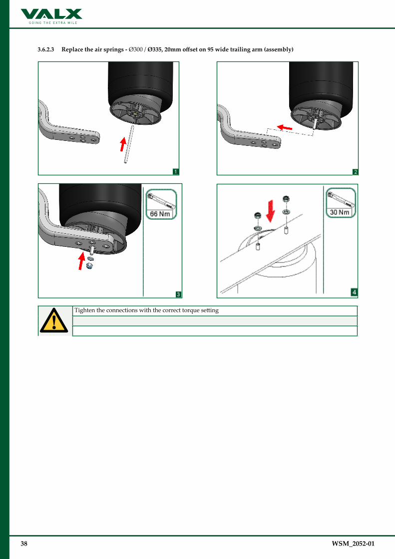
3.6.2.3 Replace the air springs - Ø300 / Ø335,20mmoffseton95widetrailingarm(assembly)
Tighten the connections with the correct torque setting

WSM_2052-01 39
3.6.3 Replace complete air suspension
Make sure that the axle seat is well placed in the axle groove at the correct spring track
The shock absorber tube must be positioned on the vehicle insideMake sure the zinc plate is well placed between the trailing arm and axle seat Place the dowel through the zinc plate and in the hole at the rear of the axle seat
Place the trailing arm on the zinc plate, make sure the dowel falls in the hole in the trailing arm
Pull the trailing arm to the frontPlace the U-bolt plates over the trailing armPlace the U-bolt plate with the long legs at the front and with the arrow pointing in the travel direction
Place the U-bolts around the axle and through the U-bolt plates
Tighten the wheelnuts slightly (hand tighten) until the u-bolts are positioned against the axle tube
Check the sping track again by measuring the distance through the spring eyes
Adjust the spring track to the correct track with a rubber hammer if necessaryTolerance spring track: +/- 2mm
SPRING TRACK

40 WSM_2052-01
3.6.3 Replace complete air suspension (continued)
Check the distance between the trailing arm eye and the hubface on both sides of the axle
The distance should be the same on both sidesAdjust the alignment with a rubber hammer if necessaryTolerance alignment: LEFT = RIGHT +/- 2mm
Tighten the U-bolts crossewise and evenly on both sides
Check, after tightening, if the spring track and air spring alignment are within toleranceThe thread lengths from the U-bolts must be evenly above the nuts
Torqueitem size widthacrossflats inspection when replacing
1 axle clamp M22 32 600 Nm 600 Nm (+25/-0)
LEFT SIDE = RIGHT SIDE