Embed Size (px)
Citation preview
Valvola a solenoide a due e tre vie
Two-way and three-way solenoid
valve
Vanne à solenoide à deux et trois
voies
2- und 3-Wege Magnetventil
S1 - S2
S1 - S2
6
I dati del presente prospetto sono forniti in buona fede. La FIP non si assume alcu-na responsabilità su quei dati non diret-tamente derivati da norme internazionali. La FIP si riserva di apportarvi qualsiasi modifica.
The data given in this leaflet are offered in good faith. No liability can be accepted concerning technical data that are not directly covered by recognized interna-tional standards. FIP reserves the right to carry out any modification to the products shown in this Ieaflet.
Les données contenues dans cette brochure sont fournies en bonne foi. FIP n’assume aucune responsabilité pour les données qui ne dérivent pas directement des normes internationa-les. FIP garde le droit d’apporter toute modification aux produits présentés dans cette brochure.
Alle Daten dieser Druckschrift wurden nach bestem Wissen angegeben, jedoch besteht keine Verbindlichkeit, sofern sie nicht direkt internationalen Normen entnommen wurden. Die Änderung von Maßen oder Ausführungen bleibt FIP vorbehalten.
S1 - S2
7
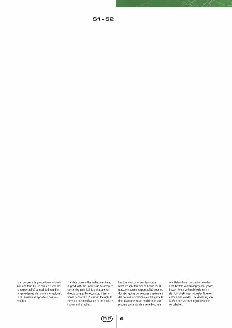
Valvola a solenoide a due e tre vie
Two-way and three-way solenoid valve
Vanne à solenoide à deux et trois voies
2 und 3 Wege-MagnetventiI
• Corpo in PVC-U disponibile in con-figurazione a 2 vie (S12 e S22) o a tre vie (S13 e S23).
• Flessibilita di installazione e facilità di manutenzione: attuatore elettrico a solenoide ad alte prestazioni proget-tato per superare i 5 milioni di cicli di manovra senza manutenzione
Bobina a sezione circolare orientabi-le con grado di protezione IP65.
• Comando manuale integrato con possibilità di essere installato in 3 differenti posizioni.
• Otturatore a leverismo in EPDM o FPM e leva in acciaio INOX.
• Connettore elettrico DIN 43650 for-nito di serie: comprende indicatore luminoso a LED e raddrizzatore (nel caso di bobina in corrente alternata).
• Adatta all’utilizzo con fluidi aggres-sivi: nessun componente metallico in contatto con il fluido o l’ambien-te esterno; tutte le viti sono coper-te da tappi di protezione in PE.
• PVC-U unionised body available with 2/2 way (versions S12 and S22) and 3/2 way (versions S13 and S23).
• Installation and maintenance friendly design: high ciclying life time electric solenoid actuator with moving internal components designed to exceed 5 million cycles without maintenance. Slewing round shape coil, IP65 protection class.
• Integrated manual override with the possibility to be installed in three different positions.
• EPDM or FPM Lever type shutter with SS lever.
• DIN 43650 Electrical connector supplied as standard including LED indicator and a rectifier (in case of AC coil).
• Corrosion resistant: metallic parts isolated from fluids and external environment; all screws are pro-tected by PE caps.
• Vannes au corp en PVC-U avec raccords union disponibles avec 2/2 voies (versions S12 et S22) et 3/2 voies (versions S13 et S23).
• Flexibilité de installation et facilité de entretien: actionneur à électrovanne avec haute performance projeté pour excéder les 5 millions de cycles d’exploitation sans maintenance. Bobine réglable à section circulaire en classe de protection IP65.
• Contrôle manuel intégré avec la possibilité d’être installé dans 3 différentes positions.
• Obturateur à levier en EPDM ou FPM et levier en Acier inoxydable
• Connecteur électrique fourni en standard DIN 43650: comprend in-dicateur LED et un redresseur (dans le cas de bobine AC).
• Approprié pour l’usage avec des fluides agressifs: aucun composant métallique en contact avec le fluide ou l’environnement extérieur, toutes les vis sont recouvertes de capuchons de protection en PE.
• Gehäuse aus PVC-U, erhältlich als 2/2 Wege Ausführung (S12 und S22) und 3/2 Wege Ausführung (S13 und S23). Große Auswahl an Anschlüssen nach verschiedenen Normen.
• Flexibler Einbau und wartungs-freundliche Konstruktion: Hohe Lebensdauer der Magnetspule, mit beweglichen Bauteilen, ausgelegt für über 5 Millionen wartungsfreie Bedienzyklen. Verstellbare Spule, Schutzart IP65.
• Integrierte Handnotbetätigung mit drei möglichen Positionen.
• Hebel-Anker-System EPDM oder FPM und Hebel aus Edelstahl.
• Stecker für elektrischen Anschluss DIN 43650 serienmäßig: mit Kontrollleuchte (LED) und Gleichrichter (bei einer Spule mit Wechselstrom).
• Geeignet für den Einsatz mit ag-gressiven Flüssigkeiten: metallische Bauteile kommen nicht mit dem Medium und der Atmosphäre in Berührung, alle Schrauben sind mit Schutzkappen aus PE abgedeckt.
LEGENDA
d Rohraußendurchmesser mm
DN Nennweite, mm
R Gewinde (DIN 2999, T1)
PN Nenndruck, bar (max Betriebsdruck bei 20° C Wasser)
g Gewicht in Gramm
PVC-U Polyvinylchlorid, hart ohne Weichmacher
EPDM Äthylen-Propylen- Kautschuk
FPM (FKM) Fluor-Kautschuk
PE Polyethylen
PP-GR Polypropylen glasfaserverstärkt
d diametro nominale esterno del tubo in mm
DN diametro nominale interno in mm
R dimensione nominale della filettatura in pollici
PN pressione nominale in bar (pressione max di eserci-zio a 20° C - acqua)
g peso in grammi
PVC-U cloruro di polivinile rigido
EPDM elastomero etilene propilene
FPM (FKM) fluoroelastomero
PE polietilene
PP-GR polipropilene rinforzato fibra di vetro
d nominal outside diameter of the pipe in mm
DN nominal internal diameter in mm
R nominal size of the thread in inches
PN nominal pressure in bar (max. working pressure at 20° C - water)
g weight in grams
PVC-U unplasticized polyvinyl chloride
EPDM ethylene propylene rubber
FPM (FKM) vinylidene fluoride rubber
PE polyethylene
PP-GR fiber glass reinforced polypropylene
d diamètre extérieur nominal du tube en mm
DN diamétre nominal intérieur en mm
R dimension nominale du filetage en pouces
PN pression nominale en bar (pression de service max à 20° O - eau)
g poids en grammes
PVC-U polychlorure de vinyle non plastifié
EPDM élastomère éthylène-propylène
FPM (FKM) fluorélastomère de vinylidène
PE polyéthylène
PP-GR polypropylène renforcé fibres de verre
S1 - S2
8
Dati Tecnici
Technical Data
Données Techniques
TechnischeDaten
°C10020 60 800 40bar
8
6
4
2
0pres
sione
di e
serc
izio
- wor
king
pre
ssur
epr
essio
n de
ser
vice
- Be
trieb
sdru
ck
temperatura di esercizio - working temperaturetempérature de service - Betriebstemperatur
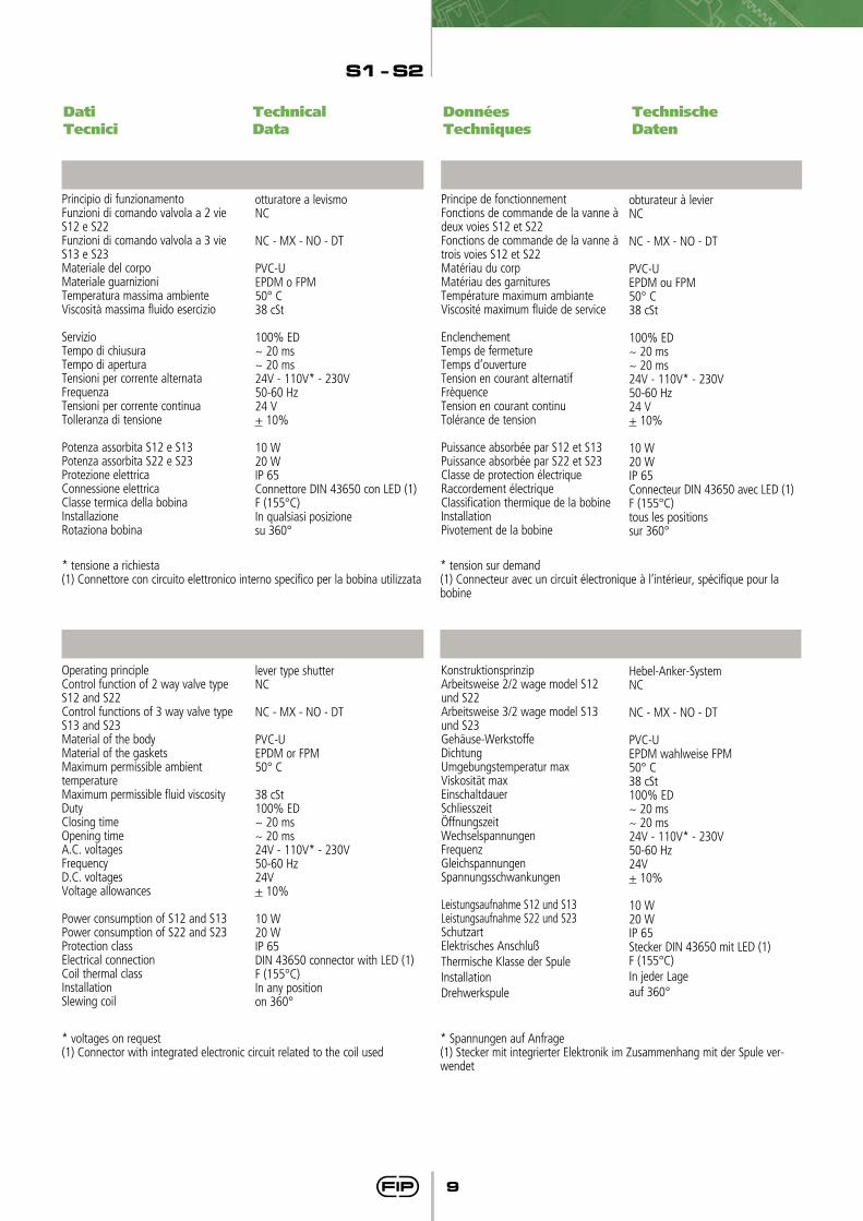
Prestazioni valvola a 2 vie tipo S12
Prestazioni valvola a 2 vie tipo S22
Prestazioni valvola a 3 vie tipo S13
Prestazioni valvola a 3 vie tipo S23
Performances of two way valve type S12
Performances of two way valve type S22
Performances of three way valve type S13
Performances of three way valve type S23
Performances de la vanne à deux voies S12
Performances de la vanne à deux voies S22
Performances de la vanne à trois voies S13
Performances de la vanne à trois voies S23
Betriebsdaten 2/2 Wege Ventil Model S12
Betriebsdaten 2/2 Wege Ventil Model S22
Betriebsdaten 3/2 Wege Ventil Model S13
Betriebsdaten 3/2 Wege Ventil Model S23
46
6,7
DNPN
kv(l/min)*
S12
82
15,3
64
12,1
NCMXNODT
NCMXNODT
DN
PN
kv(l/min)*
S13
8
0,60,40,61,5
12,813,3
1313,8
4
2,51
2,54
6,26,36,46,8
6
1,20,51,22,5
9,610,8
1011,6
8
2,51,5
36
13,617,515,8
20
NCMXNODT
NCMXNODT
DN
PN
kv(l/min)*
S23
15
0,50,5
12
56,657,555,860,3
10
1,51
1,54
3030,8
2932,5
86
27,5
DNPN
kv(l/min)*
S22
152
58,3
104
34,2
*∆P 1 bar
1
3
5
1
2
3
4
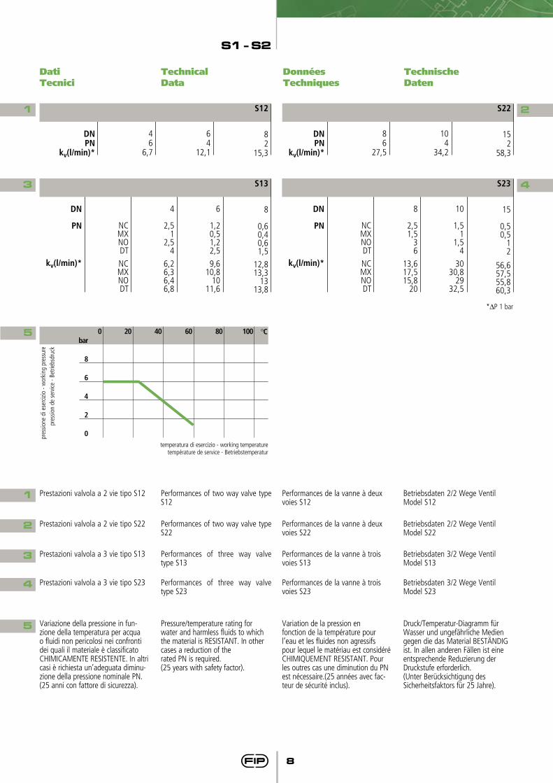
5 Variazione della pressione in fun-zione della temperatura per acqua o fluidi non pericolosi nei confronti dei quali il materiale è classificato CHIMICAMENTE RESISTENTE. In altri casi è richiesta un’adeguata diminu-zione della pressione nominale PN. (25 anni con fattore di sicurezza).
Pressure/temperature rating forwater and harmless fluids to which the material is RESISTANT. In other cases a reduction of therated PN is required.(25 years with safety factor).
Variation de la pression enfonction de la température pourl’eau et les fluides non agressifspour lequel le matériau est considéré CHIMIQUEMENT RESISTANT. Pour les outres cas une diminution du PN est nécessaire.(25 années avec fac-teur de sécurité inclus).
Druck/Temperatur-Diagramm fürWasser und ungefährliche Mediengegen die das Material BESTÄNDIG ist. In allen anderen Fällen ist eineentsprechende Reduzierung derDruckstufe erforderlich.(Unter Berücksichtigung des Sicherheitsfaktors für 25 Jahre).
2
4
S1 - S2
9
Dati Tecnici
Technical Data
Données Techniques
TechnischeDaten
Principio di funzionamentoFunzioni di comando valvola a 2 vie S12 e S22Funzioni di comando valvola a 3 vie S13 e S23Materiale del corpoMateriale guarnizioniTemperatura massima ambienteViscosità massima fluido esercizio
ServizioTempo di chiusuraTempo di aperturaTensioni per corrente alternataFrequenza Tensioni per corrente continuaTolleranza di tensione
Potenza assorbita S12 e S13Potenza assorbita S22 e S23 Protezione elettrica Connessione elettricaClasse termica della bobinaInstallazioneRotaziona bobina
* tensione a richiesta(1) Connettore con circuito elettronico interno specifico per la bobina utilizzata
* voltages on request(1) Connector with integrated electronic circuit related to the coil used
* Spannungen auf Anfrage(1) Stecker mit integrierter Elektronik im Zusammenhang mit der Spule ver-wendet
* tension sur demand(1) Connecteur avec un circuit électronique à l’intérieur, spécifique pour la bobine
otturatore a levismoNC
NC - MX - NO - DT
PVC-UEPDM o FPM50° C38 cSt
100% ED~ 20 ms~ 20 ms24V - 110V* - 230V50-60 Hz24 V+ 10%
10 W20 WIP 65Connettore DIN 43650 con LED (1)F (155°C)In qualsiasi posizionesu 360°
Operating principleControl function of 2 way valve type S12 and S22Control functions of 3 way valve type S13 and S23Material of the bodyMaterial of the gasketsMaximum permissible ambienttemperatureMaximum permissible fluid viscosityDutyClosing timeOpening timeA.C. voltagesFrequency D.C. voltagesVoltage allowances
Power consumption of S12 and S13 Power consumption of S22 and S23 Protection class Electrical connectionCoil thermal classInstallationSlewing coil
lever type shutterNC
NC - MX - NO - DT
PVC-UEPDM or FPM50° C
38 cSt100% ED~ 20 ms~ 20 ms24V - 110V* - 230V50-60 Hz24V+ 10%
10 W20 WIP 65DIN 43650 connector with LED (1)F (155°C)In any positionon 360°
Principe de fonctionnementFonctions de commande de la vanne à deux voies S12 et S22Fonctions de commande de la vanne à trois voies S12 et S22Matériau du corpMatériau des garnituresTempérature maximum ambianteViscosité maximum fluide de service
EnclenchementTemps de fermetureTemps d’ouvertureTension en courant alternatifFrèquence Tension en courant continuTolérance de tension
Puissance absorbée par S12 et S13 Puissance absorbée par S22 et S23Classe de protection électrique Raccordement électriqueClassification thermique de la bobineInstallationPivotement de la bobine
obturateur à levierNC
NC - MX - NO - DT
PVC-UEPDM ou FPM50° C38 cSt
100% ED~ 20 ms~ 20 ms24V - 110V* - 230V50-60 Hz24 V+ 10%
10 W20 WIP 65Connecteur DIN 43650 avec LED (1)F (155°C)tous les positionssur 360°
KonstruktionsprinzipArbeitsweise 2/2 wage model S12 und S22Arbeitsweise 3/2 wage model S13und S23Gehäuse-WerkstoffeDichtungUmgebungstemperatur maxViskosität maxEinschaltdauerSchliesszeitÖffnungszeitWechselspannungenFrequenz GleichspannungenSpannungsschwankungen
Leistungsaufnahme S12 und S13Leistungsaufnahme S22 und S23 SchutzartElektrisches AnschlußThermische Klasse der SpuleInstallationDrehwerkspule
Hebel-Anker-SystemNC
NC - MX - NO - DT
PVC-UEPDM wahlweise FPM50° C38 cSt100% ED~ 20 ms~ 20 ms24V - 110V* - 230V50-60 Hz24V+ 10%
10 W20 WIP 65Stecker DIN 43650 mit LED (1) F (155°C)In jeder Lageauf 360°
S1 - S2
10
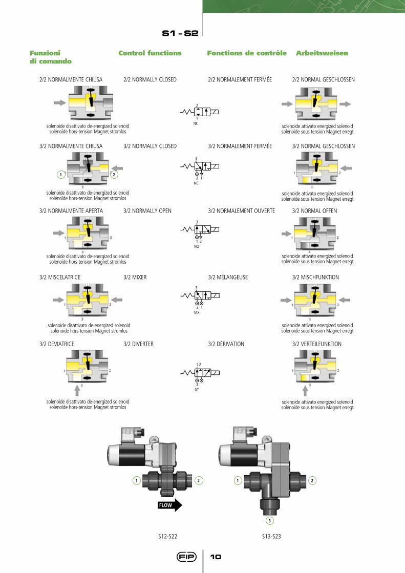
2/2 NORMALMENTE CHIUSA 2/2 NORMALLY CLOSED 2/2 NORMALEMENT FERMÉE 2/2 NORMAL GESCHLOSSEN
3/2 NORMALMENTE CHIUSA 3/2 NORMALLY CLOSED 3/2 NORMALEMENT FERMÉE 3/2 NORMAL GESCHLOSSEN
3/2 NORMALMENTE APERTA 3/2 NORMALLY OPEN 3/2 NORMALEMENT OUVERTE 3/2 NORMAL OFFEN
3/2 MISCELATRICE 3/2 MIXER 3/2 MÉLANGEUSE 3/2 MISCHFUNKTION
3/2 DEVIATRICE 3/2 DIVERTER 3/2 DÉRIVATION 3/2 VERTEILFUNKTION
Funzioni di comando
Control functions Fonctions de contrôle Arbeitsweisen
solenoide disattivato de-energized solenoidsolénoïde hors-tension Magnet stromlos
solenoide disattivato de-energized solenoidsolénoïde hors-tension Magnet stromlos
solenoide disattivato de-energized solenoidsolénoïde hors-tension Magnet stromlos
solenoide disattivato de-energized solenoidsolénoïde hors-tension Magnet stromlos
solenoide disattivato de-energized solenoidsolénoïde hors-tension Magnet stromlos
solenoide attivato energized solenoidsolénoïde sous tension Magnet erregt
solenoide attivato energized solenoidsolénoïde sous tension Magnet erregt
solenoide attivato energized solenoidsolénoïde sous tension Magnet erregt
solenoide attivato energized solenoidsolénoïde sous tension Magnet erregt
solenoide attivato energized solenoidsolénoïde sous tension Magnet erregt
1 2
FLOW
1 12 2
3
S12-S22 S13-S23
S1 - S2
11
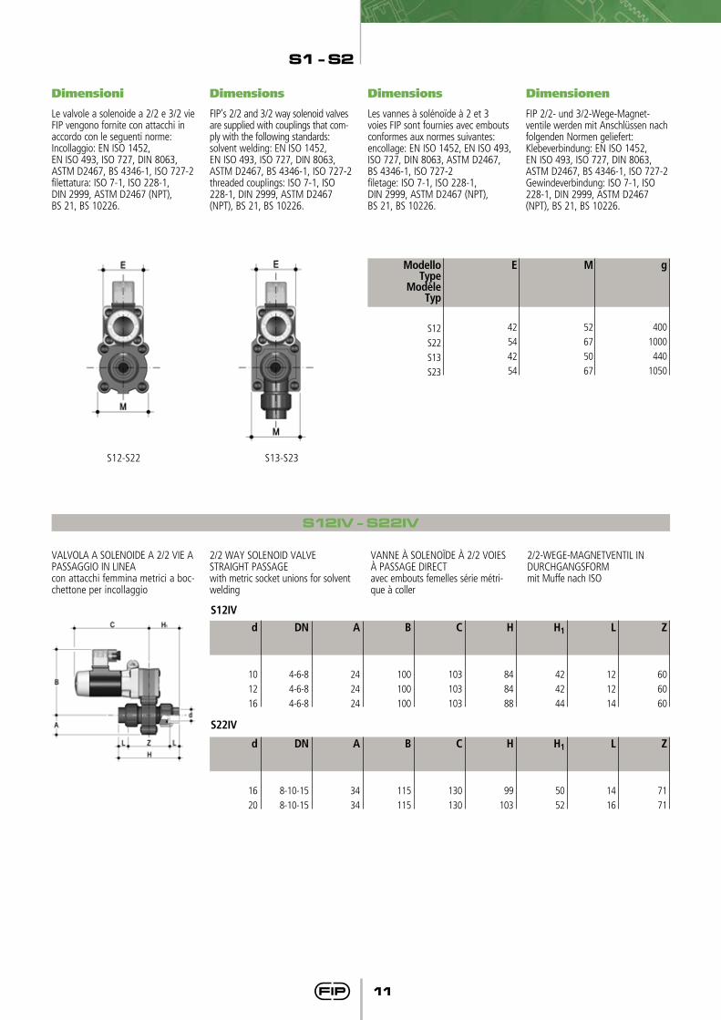
Dimensioni Dimensions Dimensions Dimensionen
Le valvole a solenoide a 2/2 e 3/2 vie FIP vengono fornite con attacchi in accordo con le seguenti norme:Incollaggio: EN ISO 1452, EN ISO 493, ISO 727, DIN 8063, ASTM D2467, BS 4346-1, ISO 727-2filettatura: ISO 7-1, ISO 228-1, DIN 2999, ASTM D2467 (NPT), BS 21, BS 10226.
FIP’s 2/2 and 3/2 way solenoid vaIves are supplied with couplings that com-ply with the following standards:solvent welding: EN ISO 1452, EN ISO 493, ISO 727, DIN 8063, ASTM D2467, BS 4346-1, ISO 727-2threaded couplings: ISO 7-1, ISO 228-1, DIN 2999, ASTM D2467 (NPT), BS 21, BS 10226.
Les vannes à solénoïde à 2 et 3 voies FIP sont fournies avec embouts conformes aux normes suivantes:encollage: EN ISO 1452, EN ISO 493, ISO 727, DIN 8063, ASTM D2467, BS 4346-1, ISO 727-2filetage: ISO 7-1, ISO 228-1, DIN 2999, ASTM D2467 (NPT), BS 21, BS 10226.
FIP 2/2- und 3/2-Wege-Magnet-ventile werden mit Anschlüssen nach folgenden Normen geliefert:Klebeverbindung: EN ISO 1452, EN ISO 493, ISO 727, DIN 8063, ASTM D2467, BS 4346-1, ISO 727-2Gewindeverbindung: ISO 7-1, ISO 228-1, DIN 2999, ASTM D2467 (NPT), BS 21, BS 10226.
S12IV - S22IV
VALVOLA A SOLENOIDE A 2/2 VIE A PASSAGGIO IN LINEAcon attacchi femmina metrici a boc-chettone per incollaggio
2/2 WAY SOLENOID VALVESTRAIGHT PASSAGE with metric socket unions for solvent welding
VANNE À SOLENOÏDE À 2/2 VOIES À PASSAGE DIRECTavec embouts femelles série métri-que à coller
2/2-WEGE-MAGNETVENTIL IN DURCHGANGSFORM mit Muffe nach ISO
L
12
12
14
Z
60
60
60
H1
42
42
44
H
84
84
88
C
103
103
103
B
100
100
100
A
24
24
24
DN
4-6-8
4-6-8
4-6-8
d
10
12
16
S12IV
S22IV
L
14
16
Z
71
71
H1
50
52
H
99
103
C
130
130
B
115
115
A
34
34
DN
8-10-15
8-10-15
d
16
20
g
400
1000
440
1050
ModelloType
ModèleTyp
S12
S22
S13
S23
E
42
54
42
54
M
52
67
50
67
S12-S22 S13-S23
S1 - S2
12
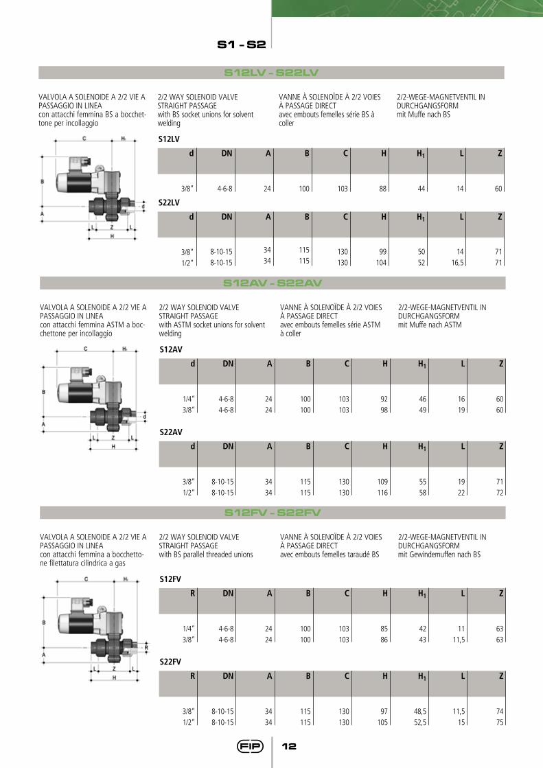
S12LV
L
14
Z
60
H1
44
H
88
C
103
B
100
A
24
DN
4-6-8
d
3/8”
S22LV
L
14
16,5
Z
71
71
H1
50
52
H
99
104
C
130
130
B
115
115
A
34
34
DN
8-10-15
8-10-15
d
3/8”
1/2”
S12LV - S22LV
VALVOLA A SOLENOIDE A 2/2 VIE A PASSAGGIO IN LINEAcon attacchi femmina BS a bocchet-tone per incollaggio
2/2 WAY SOLENOID VALVESTRAIGHT PASSAGE with BS socket unions for solvent welding
VANNE À SOLENOÏDE À 2/2 VOIES À PASSAGE DIRECTavec embouts femelles série BS à coller
2/2-WEGE-MAGNETVENTIL IN DURCHGANGSFORM mit Muffe nach BS
S22AV
L
19
22
Z
71
72
H1
55
58
H
109
116
C
130
130
B
115
115
A
34
34
DN
8-10-15
8-10-15
d
3/8”
1/2”
S12AV - S22AV
VALVOLA A SOLENOIDE A 2/2 VIE A PASSAGGIO IN LINEAcon attacchi femmina ASTM a boc-chettone per incollaggio
2/2 WAY SOLENOID VALVESTRAIGHT PASSAGE with ASTM socket unions for solvent welding
VANNE À SOLENOÏDE À 2/2 VOIES À PASSAGE DIRECTavec embouts femelles série ASTM à coller
2/2-WEGE-MAGNETVENTIL IN DURCHGANGSFORM mit Muffe nach ASTM
S12AV
L
16
19
Z
60
60
H1
46
49
H
92
98
C
103
103
B
100
100
A
24
24
DN
4-6-8
4-6-8
d
1/4”
3/8”
S22FV
L
11,5
15
Z
74
75
H1
48,5
52,5
H
97
105
C
130
130
B
115
115
A
34
34
DN
8-10-15
8-10-15
R
3/8”
1/2”
S12FV - S22FV
VALVOLA A SOLENOIDE A 2/2 VIE A PASSAGGIO IN LINEAcon attacchi femmina a bocchetto-ne filettatura cilindrica a gas
2/2 WAY SOLENOID VALVESTRAIGHT PASSAGE with BS parallel threaded unions
VANNE À SOLENOÏDE À 2/2 VOIES À PASSAGE DIRECTavec embouts femelles taraudé BS
2/2-WEGE-MAGNETVENTIL IN DURCHGANGSFORM mit Gewindemuffen nach BS
S12FV
L
11
11,5
Z
63
63
H1
42
43
H
85
86
C
103
103
B
100
100
A
24
24
DN
4-6-8
4-6-8
R
1/4”
3/8”
S1 - S2
13
S22NV
L
16
20,5
Z
71
71
H1
51,5
56
H
103
112
C
130
130
B
115
115
A
34
34
DN
8-10-15
8-10-15
R
3/8”
1/2”
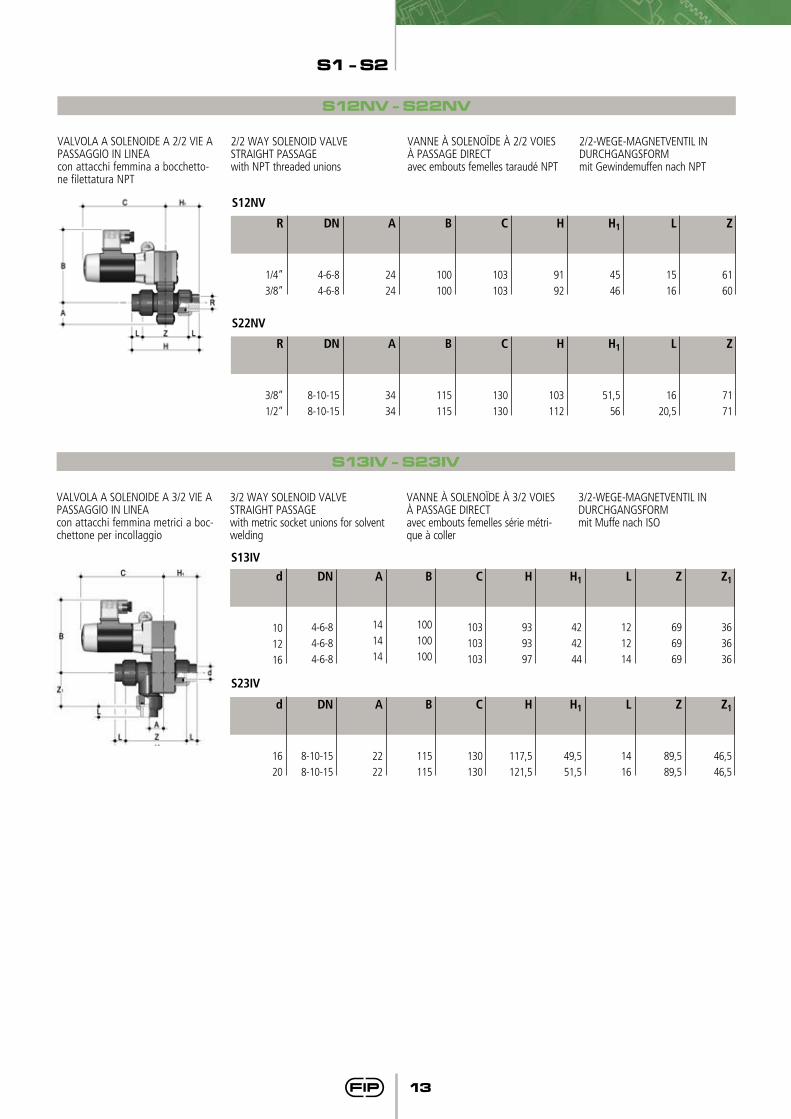
S12NV - S22NV
VALVOLA A SOLENOIDE A 2/2 VIE A PASSAGGIO IN LINEAcon attacchi femmina a bocchetto-ne filettatura NPT
2/2 WAY SOLENOID VALVESTRAIGHT PASSAGE with NPT threaded unions
VANNE À SOLENOÏDE À 2/2 VOIES À PASSAGE DIRECTavec embouts femelles taraudé NPT
2/2-WEGE-MAGNETVENTIL IN DURCHGANGSFORM mit Gewindemuffen nach NPT
S12NV
L
15
16
Z
61
60
H1
45
46
H
91
92
C
103
103
B
100
100
A
24
24
DN
4-6-8
4-6-8
R
1/4”
3/8”
S13IV - S23IV
VALVOLA A SOLENOIDE A 3/2 VIE A PASSAGGIO IN LINEAcon attacchi femmina metrici a boc-chettone per incollaggio
3/2 WAY SOLENOID VALVESTRAIGHT PASSAGE with metric socket unions for solvent welding
VANNE À SOLENOÏDE À 3/2 VOIES À PASSAGE DIRECTavec embouts femelles série métri-que à coller
3/2-WEGE-MAGNETVENTIL IN DURCHGANGSFORM mit Muffe nach ISO
L
12
12
14
L
14
16
Z1
36
36
36
Z1
46,5
46,5
Z
69
69
69
Z
89,5
89,5
H1
42
42
44
H1
49,5
51,5
H
93
93
97
H
117,5
121,5
C
103
103
103
C
130
130
B
100
100
100
B
115
115
A
14
14
14
A
22
22
DN
4-6-8
4-6-8
4-6-8
DN
8-10-15
8-10-15
d
10
12
16
d
16
20
S13IV
S23IV
S1 - S2
14
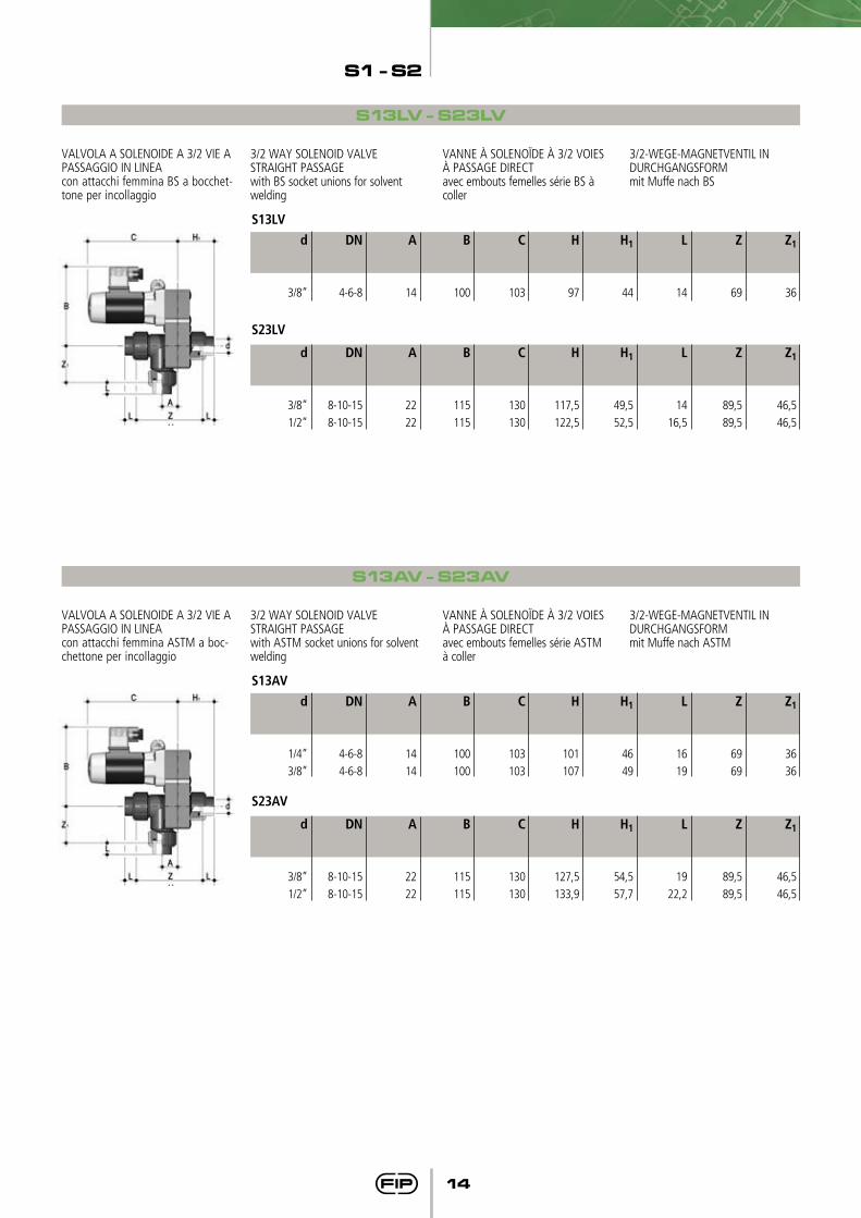
S13LV - S23LV
L
14
Z1
36
Z
69
H1
44
H
97
C
103
B
100
A
14
DN
4-6-8
d
3/8”
S13LV
L
14
16,5
Z1
46,5
46,5
Z
89,5
89,5
H1
49,5
52,5
H
117,5
122,5
C
130
130
B
115
115
A
22
22
DN
8-10-15
8-10-15
d
3/8”
1/2”
S23LV
VALVOLA A SOLENOIDE A 3/2 VIE A PASSAGGIO IN LINEAcon attacchi femmina BS a bocchet-tone per incollaggio
3/2 WAY SOLENOID VALVESTRAIGHT PASSAGE with BS socket unions for solvent welding
VANNE À SOLENOÏDE À 3/2 VOIES À PASSAGE DIRECTavec embouts femelles série BS à coller
3/2-WEGE-MAGNETVENTIL IN DURCHGANGSFORM mit Muffe nach BS
S13AV - S23AV
L
16
19
Z1
36
36
Z
69
69
H1
46
49
H
101
107
C
103
103
B
100
100
A
14
14
DN
4-6-8
4-6-8
d
1/4”
3/8”
S13AV
L
19
22,2
Z1
46,5
46,5
Z
89,5
89,5
H1
54,5
57,7
H
127,5
133,9
C
130
130
B
115
115
A
22
22
DN
8-10-15
8-10-15
d
3/8”
1/2”
S23AV
VALVOLA A SOLENOIDE A 3/2 VIE A PASSAGGIO IN LINEAcon attacchi femmina ASTM a boc-chettone per incollaggio
3/2 WAY SOLENOID VALVESTRAIGHT PASSAGE with ASTM socket unions for solvent welding
VANNE À SOLENOÏDE À 3/2 VOIES À PASSAGE DIRECTavec embouts femelles série ASTM à coller
3/2-WEGE-MAGNETVENTIL IN DURCHGANGSFORM mit Muffe nach ASTM
S1 - S2
15
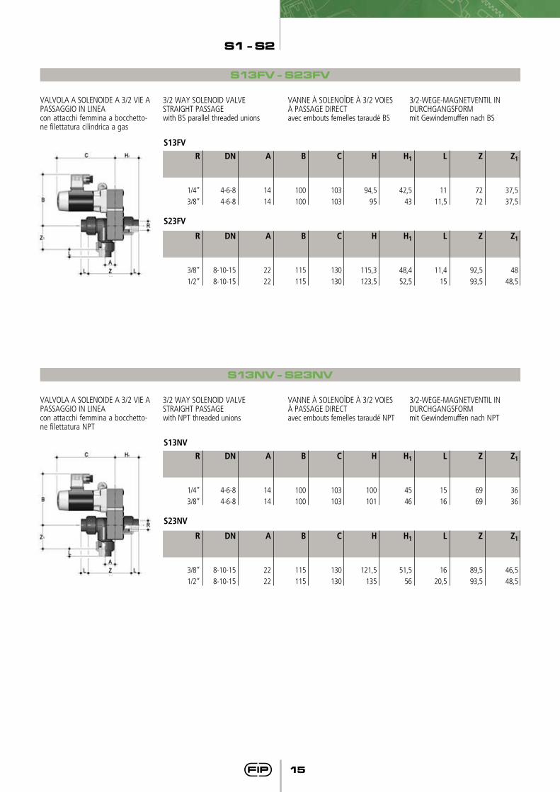
S13FV - S23FV
L
11
11,5
Z1
37,5
37,5
Z
72
72
H1
42,5
43
H
94,5
95
C
103
103
B
100
100
A
14
14
DN
4-6-8
4-6-8
R
1/4”
3/8”
S13FV
L
11,4
15
Z1
48
48,5
Z
92,5
93,5
H1
48,4
52,5
H
115,3
123,5
C
130
130
B
115
115
A
22
22
DN
8-10-15
8-10-15
R
3/8”
1/2”
S23FV
VALVOLA A SOLENOIDE A 3/2 VIE A PASSAGGIO IN LINEAcon attacchi femmina a bocchetto-ne filettatura cilindrica a gas
3/2 WAY SOLENOID VALVESTRAIGHT PASSAGE with BS parallel threaded unions
VANNE À SOLENOÏDE À 3/2 VOIES À PASSAGE DIRECTavec embouts femelles taraudé BS
3/2-WEGE-MAGNETVENTIL IN DURCHGANGSFORM mit Gewindemuffen nach BS
S13NV - S23NV
L
15
16
Z1
36
36
Z
69
69
H1
45
46
H
100
101
C
103
103
B
100
100
A
14
14
DN
4-6-8
4-6-8
R
1/4”
3/8”
S13NV
L
16
20,5
Z1
46,5
48,5
Z
89,5
93,5
H1
51,5
56
H
121,5
135
C
130
130
B
115
115
A
22
22
DN
8-10-15
8-10-15
R
3/8”
1/2”
S23NV
VALVOLA A SOLENOIDE A 3/2 VIE A PASSAGGIO IN LINEAcon attacchi femmina a bocchetto-ne filettatura NPT
3/2 WAY SOLENOID VALVESTRAIGHT PASSAGE with NPT threaded unions
VANNE À SOLENOÏDE À 3/2 VOIES À PASSAGE DIRECTavec embouts femelles taraudé NPT
3/2-WEGE-MAGNETVENTIL IN DURCHGANGSFORM mit Gewindemuffen nach NPT
S1 - S2
16
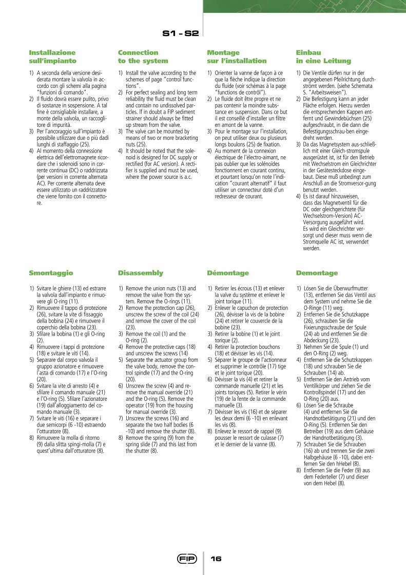
Installazione sull’impianto
1) A seconda della versione desi-derata montare la valvola in ac-cordo con gli schemi alla pagina “funzioni di comando”.
2) Il fluido dovrà essere pulito, privo di sostanze in sospensione. A tal fine è consigliabile installare, a monte della valvola, un raccogli-tore di impurità.
3) Per l’ancoraggio sull’impianto è possibile utilizzare due o più dadi lunghi di staffaggio (25).
4) Al momento della connessione elettrica dell’elettromagnete ricor-dare che i solenoidi sono in cor-rente continua (DC) o raddrizzata (per versioni in corrente alternata AC). Per corrente alternata deve essere utilizzato un raddrizzatore che viene fornito con il connetto-re.
Connection to the system
1) Install the valve according to the schemes of page “control func-tions”.
2) For perfect sealing and long term reliability the fluid must be clean and contain no undissolved par-ticles. lf in doubt a FIP sediment strainer should always be fitted up stream from the valve.
3) The valve can be mounted by means of two or more bracketing nuts (25).
4) lt should be noted that the sole-noid is designed for DC supply or rectified (for AC version). A recti-fier is supplied and must be used, where the power source is a.c.
Montage sur l’installation
1) Orienter la vanne de façon à ce que la flèche indique la direction du fluide (voir schémas à la page “functions de contrôl”).
2) Le fluide doit être propre et ne pas contenir la moindre subs-tance en suspension. Dans ce but il est conseillé d’installer un filtre en amont de la vanne.
3) Pour le montage sur l’installation, on peut utiliser deux ou plusieurs longs boulons (25) de fixation.
4) Au moment de la connexion électrique de l’électro-aimant, ne pas oublier que les solénoïdes fonctionnent en courant continu, et pourtant lorsqu’on note l’indi-cation “courant alternatif” il faut utiliser un connecteur doté d’un redresseur de courant.
Einbau in eine Leitung
1) Die Ventile dürfen nur in der angegebenen Pfeilrichtung durch-strömt werden. (siehe Schemata S. “Arbeitsweisen”).
2) Die Befestigung kann an jeder Fläche erfolgen. Hierzu werden die entsprechenden Kappen ent-fernt und Gewindebüchsen (25)aufgeschraubt, in die dann die Befestigungsschrau-ben einge-dreht werden.
3) Da das Magnetsystem aus-schließ-lich mit einer Gleich-stromspule ausgerüstet ist, ist für den Betrieb mit Wechselstrom ein Gleichrichter in der Gerätesteckdose einge-baut. Diese muß unbedingt zum Anschluß an die Stromversor-gung benutzt werden.
4) Es ist darauf hinzuweisen, dass das Magnetventil für die DC oder gleichgerichtete (für Wechselstrom-Version) AC-Versorgung ausgeführt wird.
Es wird ein Gleichrichter ver-sorgt und dieser muss wenn die Stromquelle AC ist, verwendet werden.
Smontaggio
1) Svitare le ghiere (13) ed estrarre la valvola dall’impianto e rimuo-vere gli O-ring (11).
2) Rimuovere il tappo di protezione (26), svitare la vite di fissaggio della bobina (24) e rimuovere il coperchio della bobina (23).
3) Sfilare la bobina (1) e gli O-ring (2).
4) Rimuovere i tappi di protezione (18) e svitare le viti (14).
5) Separare dal corpo valvola il gruppo azionatore e rimuovere l’asta di comando (17) e l’O-ring (20).
6) Svitare la vite di arresto (4) e sfilare il comando manuale (21) e l’O-ring (5). Sfilare l’azionatore (19) dall’alloggiamento del co-mando manuale (3).
7) Svitare le viti (16) e separare i due semicorpi (6 -10) estraendo l’otturatore (8).
8) Rimuovere la molla di ritorno (9) dalla slitta spingi-molla (7) e quest’ultima dall’otturatore (8).
Disassembly
1) Remove the union nuts (13) and remove the valve from the sys-tem. Remove the O-rings (11).
2) Remove the protection cap (26), unscrew the screw of the coil (24) and remove the cover of the coil (23).
3) Remove the coil (1) and the O-ring (2).
4) Remove the protective caps (18) and unscrew the screws (14)
5) Separate the actuator group from the valve body, remove the con-trol spindle (17) and the O-ring (20).
6) Unscrew the screw (4) and re-move the manual override (21) and the O-ring (5). Remove the operator (19) from the housing for manual override (3).
7) Unscrew the screws (16) and separate the two half bodies (6 -10) and remove the shutter (8).
8) Remove the spring (9) from the spring slide (7) and this last from the shutter (8).
Démontage
1) Retirer les écrous (13) et enlever la valve du système et enlever le joint torique (11).
2) Enlever le capuchon de protection (26), dévisser la vis de la bobine (24) et retirer le couvercle de la bobine (23).
3) Retirer la bobine (1) et le joint torique (2).
4) Retirer la protection bouchons (18) et dévisser les vis (14).
5) Séparer le groupe de l’actionneur et supprimer le contrôle (17) tige et le joint torique (20).
6) Dévisser la vis (4) et retirer la commande manuelle (21) et les joints toriques (5). Retirer le vérin (19) de la fente de la commande manuelle (3).
7) Dévisser les vis (16) et de séparer les deux demi (6 -10) en enlevant les vis (8).
8) Enlevez le ressort de rappel (9) pousser le ressort de culasse (7) et le dernier de la vanne (8).
Demontage
1) Lösen Sie die Überwurfmutter (13), entfernen Sie das Ventil aus dem System und nehme Sie die O-Ringe (11) weg.
2) Entfernen Sie die Schutzkappe (26), schrauben Sie die Fixierungsschraube der Spule (24) ab und entfernen Sie die Abdeckung (23).
3) Nehmen Sie die Spule (1) und den O-Ring (2) weg.
4) Entfernen Sie die Schutzkappen (18) und schrauben Sie die Schrauben (14) ab.
5) Entfernen Sie den Antrieb vom Ventilkörper und ziehen Sie die Kontrollspindel (17) und den O-Ring (20) aus.
6) Lösen Sie die Schraube (4) und entfernen Sie die Handnotbetätigung (21) und den O-Ring (5). Entfernen Sie den Betreiber (19) aus dem Gehäuse der Handnotbetätigung (3).
7) Schrauben Sie die Schrauben (16) ab und trennen Sie die zwei Halbgehäuse (6 -10), dabei ent-fernen Sie den hHebel (8).
8) Entfernen Sie die Feder (9) aus dem Federteller (7) und dieser von dem Hebel (8).
S1 - S2
17
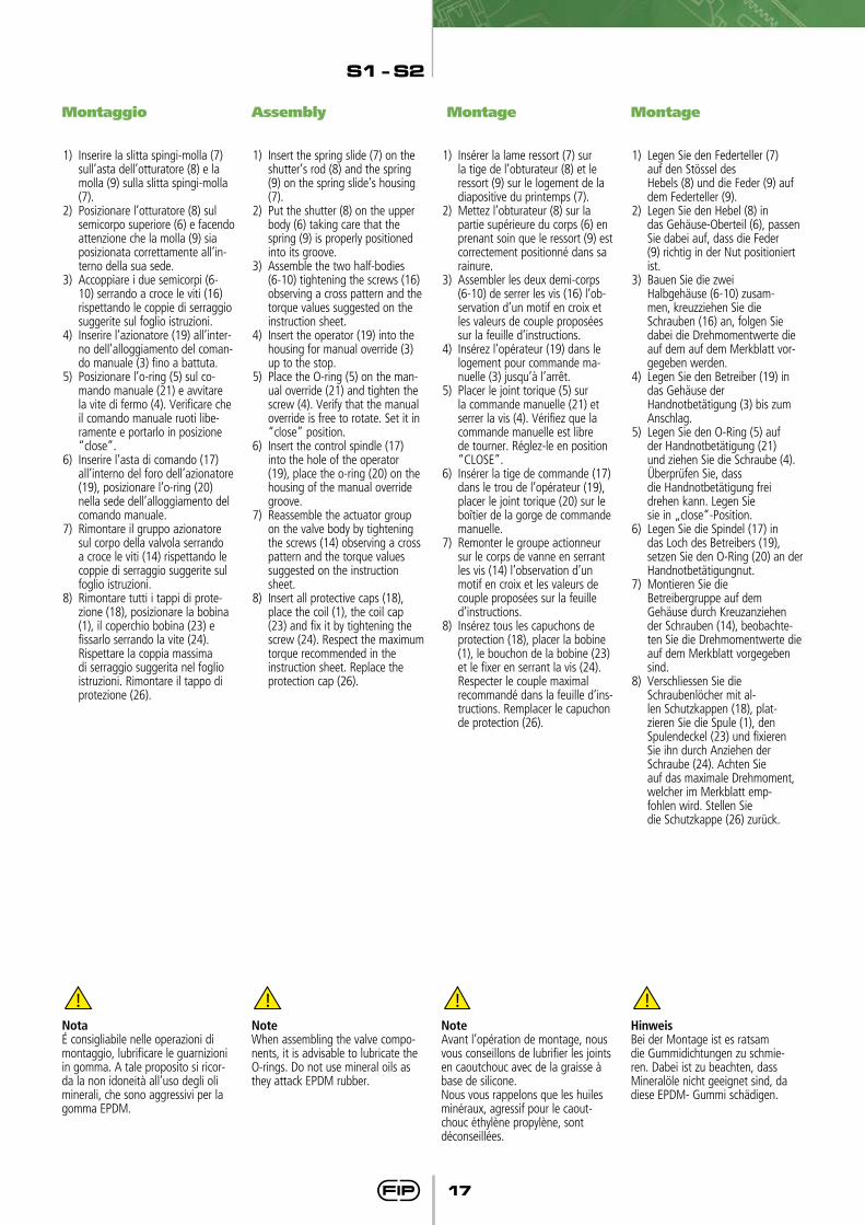
Montaggio
1) Inserire la slitta spingi-molla (7) sull’asta dell’otturatore (8) e la molla (9) sulla slitta spingi-molla (7).
2) Posizionare l’otturatore (8) sul semicorpo superiore (6) e facendo attenzione che la molla (9) sia posizionata correttamente all’in-terno della sua sede.
3) Accoppiare i due semicorpi (6-10) serrando a croce le viti (16) rispettando le coppie di serraggio suggerite sul foglio istruzioni.
4) Inserire l’azionatore (19) all’inter-no dell’alloggiamento del coman-do manuale (3) fino a battuta.
5) Posizionare l’o-ring (5) sul co-mando manuale (21) e avvitare la vite di fermo (4). Verificare che il comando manuale ruoti libe-ramente e portarlo in posizione “close”.
6) Inserire l’asta di comando (17) all’interno del foro dell’azionatore (19), posizionare l’o-ring (20) nella sede dell’alloggiamento del comando manuale.
7) Rimontare il gruppo azionatore sul corpo della valvola serrando a croce le viti (14) rispettando le coppie di serraggio suggerite sul foglio istruzioni.
8) Rimontare tutti i tappi di prote-zione (18), posizionare la bobina (1), il coperchio bobina (23) e fissarlo serrando la vite (24).Rispettare la coppia massima di serraggio suggerita nel foglio istruzioni. Rimontare il tappo di protezione (26).
Assembly
1) Insert the spring slide (7) on the shutter’s rod (8) and the spring (9) on the spring slide’s housing (7).
2) Put the shutter (8) on the upper body (6) taking care that the spring (9) is properly positioned into its groove.
3) Assemble the two half-bodies (6-10) tightening the screws (16) observing a cross pattern and the torque values suggested on the instruction sheet.
4) Insert the operator (19) into the housing for manual override (3) up to the stop.
5) Place the O-ring (5) on the man-ual override (21) and tighten the screw (4). Verify that the manual override is free to rotate. Set it in “close” position.
6) Insert the control spindle (17) into the hole of the operator (19), place the o-ring (20) on the housing of the manual override groove.
7) Reassemble the actuator group on the valve body by tightening the screws (14) observing a cross pattern and the torque values suggested on the instruction sheet.
8) Insert all protective caps (18), place the coil (1), the coil cap (23) and fix it by tightening the screw (24). Respect the maximum torque recommended in the instruction sheet. Replace the protection cap (26).
Montage
1) Insérer la lame ressort (7) sur la tige de l’obturateur (8) et le ressort (9) sur le logement de la diapositive du printemps (7).
2) Mettez l’obturateur (8) sur la partie supérieure du corps (6) en prenant soin que le ressort (9) est correctement positionné dans sa rainure.
3) Assembler les deux demi-corps (6-10) de serrer les vis (16) l’ob-servation d’un motif en croix et les valeurs de couple proposées sur la feuille d’instructions.
4) Insérez l’opérateur (19) dans le logement pour commande ma-nuelle (3) jusqu’à l’arrêt.
5) Placer le joint torique (5) sur la commande manuelle (21) et serrer la vis (4). Vérifiez que la commande manuelle est libre de tourner. Réglez-le en position “CLOSE”.
6) Insérer la tige de commande (17) dans le trou de l’opérateur (19), placer le joint torique (20) sur le boîtier de la gorge de commande manuelle.
7) Remonter le groupe actionneur sur le corps de vanne en serrant les vis (14) l’observation d’un motif en croix et les valeurs de couple proposées sur la feuille d’instructions.
8) Insérez tous les capuchons de protection (18), placer la bobine (1), le bouchon de la bobine (23) et le fixer en serrant la vis (24). Respecter le couple maximal recommandé dans la feuille d’ins-tructions. Remplacer le capuchon de protection (26).
Montage
1) Legen Sie den Federteller (7) auf den Stössel des Hebels (8) und die Feder (9) auf dem Federteller (9).
2) Legen Sie den Hebel (8) in das Gehäuse-Oberteil (6), passen Sie dabei auf, dass die Feder (9) richtig in der Nut positioniert ist.
3) Bauen Sie die zwei Halbgehäuse (6-10) zusam-men, kreuzziehen Sie die Schrauben (16) an, folgen Sie dabei die Drehmomentwerte die auf dem auf dem Merkblatt vor-gegeben werden.
4) Legen Sie den Betreiber (19) in das Gehäuse der Handnotbetätigung (3) bis zum Anschlag.
5) Legen Sie den O-Ring (5) auf der Handnotbetätigung (21) und ziehen Sie die Schraube (4). Überprüfen Sie, dass die Handnotbetätigung frei drehen kann. Legen Sie sie in „close“-Position.
6) Legen Sie die Spindel (17) in das Loch des Betreibers (19), setzen Sie den O-Ring (20) an der Handnotbetätigungnut.
7) Montieren Sie die Betreibergruppe auf dem Gehäuse durch Kreuzanziehen der Schrauben (14), beobachte-ten Sie die Drehmomentwerte die auf dem Merkblatt vorgegeben sind.
8) Verschliessen Sie die Schraubenlöcher mit al-len Schutzkappen (18), plat-zieren Sie die Spule (1), den Spulendeckel (23) und fixieren Sie ihn durch Anziehen der Schraube (24). Achten Sie auf das maximale Drehmoment, welcher im Merkblatt emp-fohlen wird. Stellen Sie die Schutzkappe (26) zurück.
NotaÉ consigliabile nelle operazioni di montaggio, lubrificare le guarnizioni in gomma. A tale proposito si ricor-da la non idoneità all’uso degli oli minerali, che sono aggressivi per la gomma EPDM.
NoteWhen assembling the valve compo-nents, it is advisable to lubricate the O-rings. Do not use mineral oils as they attack EPDM rubber.
NoteAvant l’opération de montage, nous vous conseillons de lubrifier les joints en caoutchouc avec de la graisse à base de silicone.Nous vous rappelons que les huiles minéraux, agressif pour le caout-chouc éthylène propylène, sont déconseillées.
HinweisBei der Montage ist es ratsam die Gummidichtungen zu schmie-ren. Dabei ist zu beachten, dass Mineralöle nicht geeignet sind, da diese EPDM- Gummi schädigen.
S1 - S2
18
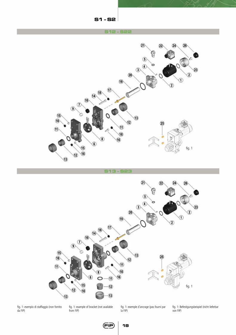
fig. 1
fig. 1: esempio di staffaggio (non fornito da FIP)
fig. 1: example of bracket (not available from FIP)
fig. 1: exemple d’ancrage (pas fourni par la FIP)
fig. 1: Befestigungsbeispiel (nicht lieferbar von FIP)
S12 - S22
S13 - S23
fig. 1
S1 - S2
19
Pos.
123456789
1011121314151617181920212223242526
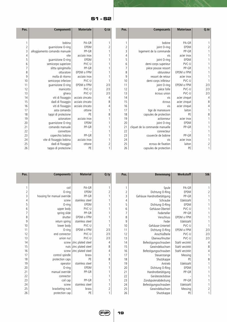
Componenti
bobinaguarnizione O-ring
alloggiamento comando manualevite
guarnizione O-ringsemicorpo superiore
slitta spingimollaotturatore
molla di ritornosemicorpo inferioreguarnizione O-ring
manicottoghiera
viti di fissaggiodadi di fissaggio
viti di fissaggioasta comando
tappi di protezioneazionatore
guarnizione O-ringcomando manuale
connettorecoperchio bobina
vite di fissaggio bobinadadi di fissaggio
tappo di protezione
Q.tà
1211111111
2/32/32/3
4841811111121
Materiale
PA-GREPDMPP-GR
acciaio inoxEPDMPVC-UPP-GR
EPDM o FPMacciaio inox
PVC-UEPDM o FPM
PVC-UPVC-U
acciaio zincatoacciaio zincatoacciaio zincato
ottonePE
acciaio inoxEPDMPP-GR
-PP-GR
acciaio inoxottone
PE
Pos.
123456789
1011121314151617181920212223242526
Composants
bobinejoint O-ring
logement de la commandevis
joint O-ringdemi-corps superieurpièce pousse ressort
obturateurressort de retour
demi-corps infèrieurjoint O-ring
pièce folleécrous union
visécrous
vistige de manoeuvre
capsules de protectionactionneur
joint O-ringcliquet de la commande manuelle
connecteurcouvercle de bobine
visecrous de fixation
capsules de protection
Q.té
1211111111
2/32/32/3
4841811111121
Materiaux
PA-GREPDMPP-GR
acier inoxEPDMPVC-UPP-GR
EPDM o FPMacier inox
PVC-UEPDM o FPM
PVC-UPVC-U
acier zinquéacier zinquéacier zinqué
laitonPE
acier inoxEPDMPP-GR
-PP-GR
acier inoxlaiton
PE
Pos.
123456789
1011121314151617181920212223242526
Components
coilO-ring
housing for manual overridescrewO-ring
upper bodyspring slide
shutterreturn spring
lower bodyO-ring
end connectorunion nut
screwnuts
screwcontrol spindleprotection caps
operatorO-ring
manual overrideconnector
coil capscrew
bracketing nutsprotection cap
Q.ty
1211111111
2/32/32/3
4841811111121
Material
PA-GREPDMPP-GR
stainless steelEPDMPVC-UPP-GR
EPDM o FPMstainless steel
PVC-UEPDM o FPM
PVC-UPVC-U
zinc plated steelzinc plated steelzinc plated steel
brassPE
stainless steelEPDMPP-GR
-PP-GR
stainless steelbrass
PE
Pos.
123456789
1011121314151617181920212223242526
Benennung
SpuleDichtung O-Ring
Gehäuse HandnotbetätigungSchraube
Dichtung O-RingGehäuse-Oberteil
FedertellerVerschluss
FederGehäuse-Unterteil
Dichtung O-RingAnschlußteile
ÜberwurfmutterBefestigungsschrauben
GewindebuchsenBefestigungsschrauben
SteuerstangeShutzkappe
AntriebDichtung O-Ring
HandnotbetätigungGerätesteckdose
ZündspulenabdeckungBefestigungsschrauben
GewindebuchsenShutzkappe
Stk
1211111111
2/32/32/3
4841811111121
Werkstoff
PA-GREPDMPP-GR
EdelstahlEPDMPVC-UPP-GR
EPDM o FPMEdelstahl
PVC-UEPDM o FPM
PVC-UPVC-U
Stahl verzinktStahl verzinktStahl verzinkt
MessingPE
EdelstahlEPDMPP-GR
-PP-GR
EdelstahlMessing
PE
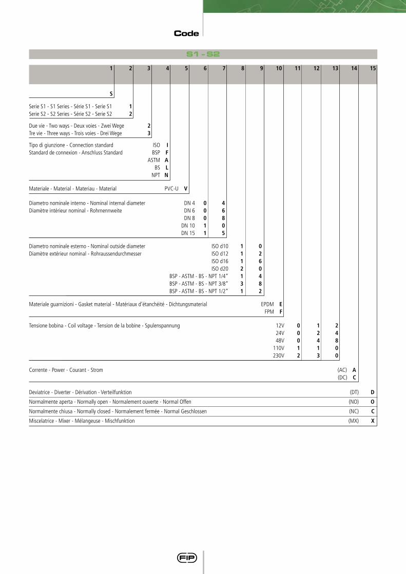
Code
S1 - S2
151 2 3 4 5 6 7 8 9 10 11 12 13 14
S
Serie S1 - S1 Series - Série S1 - Serie S1 1
Serie S2 - S2 Series - Série S2 - Serie S2 2
Due vie - Two ways - Deux voies - Zwei Wege 2
Tre vie - Three ways - Trois voies - Drei Wege 3
Materiale guarnizioni - Gasket material - Matériaux d’étanchéité - Dichtungsmaterial EPDM E FPM F
Corrente - Power - Courant - Strom (AC) A (DC) C
Materiale - Material - Materiau - Material PVC-U V
Tipo di giunzione - Connection standard ISO I
Standard de connexion - Anschluss Standard BSP F
ASTM A
BS L
NPT N
Deviatrice - Diverter - Dérivation - Verteilfunktion (DT) D
Normalmente aperta - Normally open - Normalement ouverte - Normal Offen (NO) O
Normalmente chiusa - Normally closed - Normalement fermée - Normal Geschlossen (NC) C
Miscelatrice - Mixer - Mélangeuse - Mischfunktion (MX) X
Diametro nominale interno - Nominal internal diameter DN 4 0 4
Diamètre intérieur nominal - Rohrnennweite DN 6 0 6
DN 8 0 8
DN 10 1 0
DN 15 1 5
Tensione bobina - Coil voltage - Tension de la bobine - Spulenspannung 12V 0 1 2
24V 0 2 4
48V 0 4 8
110V 1 1 0
230V 2 3 0
Diametro nominale esterno - Nominal outside diameter ISO d10 1 0
Diamètre extérieur nominal - Rohraussendurchmesser ISO d12 1 2
ISO d16 1 6
ISO d20 2 0
BSP - ASTM - BS - NPT 1/4” 1 4
BSP - ASTM - BS - NPT 3/8” 3 8
BSP - ASTM - BS - NPT 1/2” 1 2
Aliaxis Utilities & Industry S.L.U.
Aliaxis-SBC Vilamarí - C/Vilamarí, 86 Oficina 29
08015 Barcelona - España
Tel. +34 935 449 240
28020 Infanta Mercedes, 92 bajo 9 C, Madrid - España
Tel +34 914 045 847 - Fax +34 914 045 824
www.aliaxis-ui.es


![MAXON SMARTLINK CVcicsa-maxon.com.mx/media/V--lvula-de-mariposa-SMARTLINK.pdf1 - 33.9 N.m X - Special Software Version [2] 1C - Standard software Language A - English X - Special Rotation](https://img.pdfslide.us/doc/110x75/609997a6ce05bd78a2193493/maxon-smartlink-cvcicsa-maxoncommxmediav-lvula-de-mariposa-1-339-nm-x.jpg)