Embed Size (px)
Citation preview
VALVES OF HIGH -NICKEL ALLOYS
A. T. PALMetallurgist, Annapurna Metal Works, Calcutta, &
Hony. Part- time Research Fellow, BE, College, Sibpur
Abstract
The practical difficulties encountered in the
manufacture of high-nickel alloys have been enu-
merated. Some properties of the core sand , facing
and backing sands used for moulding have been
given. Suitable fluxes are mentioned, but only the
proprietary flux acted as a degassing agent and for
deoxidation . It has been noticed that despiteadoption of all precautions, porosity could not be
entirely eliminated. Author has invited remedial
suggestions to solve difficulties.
Introduction
H IGH-NICKEL alloys are corrosion-resistant alloys meant for handling
acids, alkalis, brines, water and foodproducts; they are also resistant to exposuresin dry and moist atmospheres. They are,however, particularly used where corrosion
resistance along with strength and ductilityis required. Many practical difficulties are,
however, encountered in the manufacture of
valves of high-nickel alloys and these are' :
(a) the fairly high solidification (shrinkage
- 0.25 in. per ft.), (b) the increasing ten-
dency towards the absorption of C, H and Sthereby giving rise to unsound castings,
(c) the narrower range of freezing (50°C.),(d) their high melting and pouring tempera-tures ( 1400°-1650°C_, depending on nickel
content).The principal requisites in the standard
methods so far used in the making of thesealloys are that the sand used in moulding
must be refractory and permeable2. Mouldsmust be dried in order to ensure greater per-
meability and facing sands should be of finer
mesh to produce good finish and also ofrefractory nature to resist the penetrative
action of the metal, particularly at high tem-
peratures. As the solid contraction ofcopper-nickel alloys is associated with a
tendency towards hot-shortness, any undue
resistance on the part of the moulds or coresmay give rise to cracks and tears in thecastings ; to counteract this tendency, mould-
ing sands, cores, methods of feeding, etc.,should be standardized.
Cores should be of silica sands' mixed withlinseed oil and molasses or cowdung and be
baked at a temperature high enough to ensurecomplete oxidation of the oil binder in orderto prevent undue formation of any gaswhen the alloy will lie quietly against the
same.(a) The high-nickel alloys having con-
siderable solidification shrinkage, the mostpractical way is to cast the metal through therisers, as the metal in the risers, being last tofreeze, will adequately feed the casting;moreover, where the ingates pass directly
through the feeders, the efficacy of headsand risers can be much improved by stoppingthe pouring as soon as the metal rises in them
and then filling up by pouring hot metal
directly into them-(b) Also, since these alloys have a tendency
for absorption of hydrogen, carbon andsulphur , which are the products of com-
bustion in an oil-fired furnace, the time of
melting these alloys should ba considerably
shortened; otherwise, hydrogen will cause
porosity, carbon weakness through the forma-tion of flakes and sulphur brittleness. Thestandard procedure is to melt 80-90 lb. in11 hr. Moreover, in order to reduce the
pick-up of these three elemn!nts to the mini-mum, the standard procedure is to surroundthe melting zone with free oxyge :i',2,3'4.
205
206 SYMPOSIUM ON NON-FERROUS METAL INDUSTRY IN INDIA
14' 01^
Q
nl^
A
1y B-5-P.
rIA .
b...l^ 16RI
a
a
^ol^o
SECTIONALS ELEVATION.
SECTIONAL PLAN ONA.A.
I AI.F.16
SPANNER.
I8"
E ND VIEW
G. M. BODY-IT EM NO.1
I - OFF
MAGI.4INED WHERE MARKED/
FIG. I - GUNMETAL VALVE
any absorbed oxygen being, however, re-moved by a deoxidizing treatment.
(c) & (d) Because of the narrower range
of freezing, the crucible containing the melt"
should be quickly handled and pouring should
be done as quickly as possible. Speed of
working at this stage is of vital importance,
14 DIA.
as otherwise thin-sectioned castings maytend to misrun.
More or less the same standard proceduresas discussed above were adopted in our worksto produce pressure-tight valves of high-
nickel alloys for use in chemical plants. But
the majority of the valves so far produced
r
PAL - VALVES OF HIGH-NICKEL ALLOYS 207
were found to leak under the pressure of300 lb./sq. in.
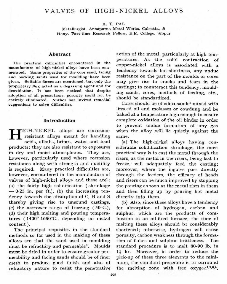
Required Specifications of the Alloyand the Valve
The composition of the alloy is as follows :Copper ... 41.0-42.0Zinc ... 0.5-1.0Manganese ... 1.75-2-25Silicon ... 1.25-1-75Tin ... 1.5-2.0Iron ... 2.0-2.5Nickel ... 50.0-52.0
The valve is to resist the action of par-ticular chemicals and to be of globe-valvetype with cast iron hand wheel, as perBritish Standard Specification. A general-view of the valve with necessary dimensionsis shown in Fig. 1.
Experimental Procedures
To prepare the cores, pure silica sand of
60-80 mesh (B.S.S.) mixed with 3 per centlinseed • oil and cowdung according to con-sistency was made in a sand-mixer. Nowater was added, The mixture had thefollowing properties :
A.F.A. Green permeability ... 60-70Green compression 1.8-2.0 lb./sq. in.Green hardness (as per test-piece) 19-5Moisture ... 11.0-11 .8 per centDry hardness ... 95Clay contents ... 2-3 per cent
Cores were baked at 450°F. for 40 to 50minutes, painted with plumbago to ensurebetter inner surface and clean stripping, andagain baked at about 450°F. for 25 to 30minutes. Cores were found too hard to bebroken and also to possess good venting pro-perties. Excessive baking, which spoils thecores, was, however, avoided.
In moulding, the facing sand was preparedwith pure silica sand of 80-90 mesh ( B.S.S.)
bonded with 2 per cent linseed oil and cow-dung according to consistency. This mixture
was found to maintain the strength afterbeing properly dried at the surface without
losing the binding properties and also tohave more or less the same properties as
above. In a mould, the amount of facing
sand was almost half, i.e. 50 per cent.The backing sand was obtained from our
cast iron foundry and had the following pro-perties (naturally-bonded sand) :
Green compression 9-9-5 lb. /sq. in.A.F.A. Green permeability ... 8-10Green hardness (as per test-piece) 70Mould hardness ... 50Moisture ... 9.0 to 9-5 per centClay contents ... 9-10 per cent
PI.AN.(1N51D€ THE MOULD-BOX
ELEVATION. `INSIDE THE MOULD-$OX.)
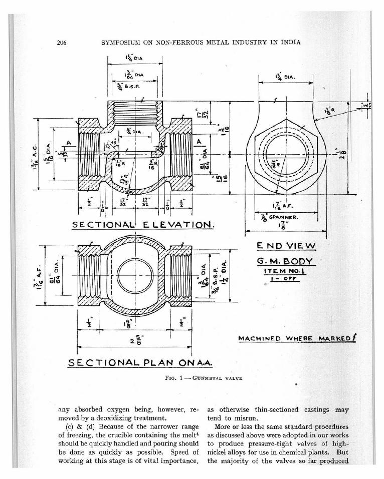
FIG. 2 - MOULDING-BOX ARRANGEMENT FOR CAST-
ING GUNMETAL VALVE . BOXES CAST HORIZONTALLY
Position 1 - (a) Melt No. 1: 2 leaked ; (b) MeltNo. 3: 1 leaked ; (c) Melt No. 4: 1 leaked.Position 2- Melt No. 2: 1 leaked. Position3 - (a) Melt No. 3: 1 leaked ; (b) Melt No. 4: 1
leaked
208
RISER
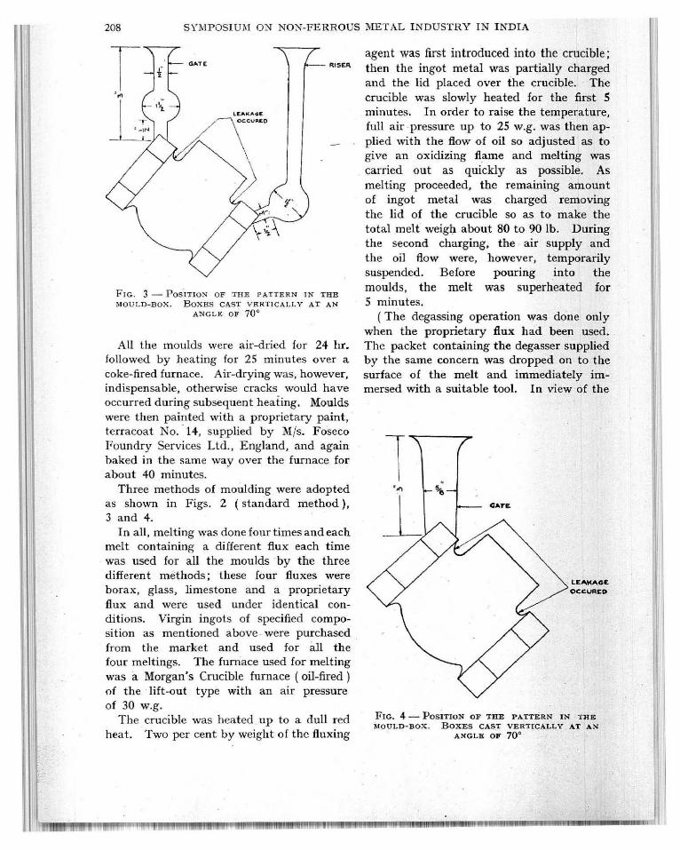
FIG. 3 - POSITION OF THE PATTERN IN THE
MOULD-BOX. BOXES CAST VERTICALLY AT AN
ANGLE OF 70'
All the moulds were air-dried for 24 hr.followed by heating for 25 minutes over acoke-fired furnace. Air-drying was, however,indispensable, otherwise cracks would haveoccurred during subsequent heating. Moulds
were then painted with a proprietary paint,terracoat No. 14, supplied by M/s. FosecoFoundry Services Ltd., England, and againbaked in the same wav over the furnace forabout 40 minutes.
Three methods of moulding were adoptedas shown in Figs. 2 (standard method),3 and 4.
In all, melting was done four times and eachmelt containing a different flux each timewas used for all the moulds by the threedifferent methods; these four fluxes wereborax, glass, limestone and a proprietary
flux and were used under identical con-ditions. Virgin ingots of specified compo-sition as mentioned above were purchased
from the market and used for all thefour meltings. The furnace used for melting
was a Morgan's Crucible furnace (oil-fired)of the lift-out type with an air pressure
of 30 w.g.The crucible was heated up to a dull red
heat. Two per cent by weight of the fluxing
SYMPOSIUM ON NON-FERROUS METAL INDUSTRY IN INDIA
agent was first introduced into the crucible;then the ingot metal was partially chargedand the lid placed over the crucible. Thecrucible was slowly heated for the first 5minutes. In order to raise the temperature,full air pressure up to 25 w.g . was then ap-plied with the flow of oil so adjusted as togive an oxidizing flame and melting wascarried out as quickly as possible. Asmelting proceeded , the remaining amountof ingot metal was charged removingthe lid of the crucible so as to make thetotal melt weigh about 80 to 90 lb . Duringthe second charging , the air supply andthe oil flow were, however, temporarilysuspended . Before pouring into themoulds, the melt was superheated for5 minutes.
(The degassing operation was done onlywhen the proprietary flux had been used.The packet containing the degasser suppliedby the same concern was dropped on to thesurface of the melt and immediately im-mersed with a suitable tool. In view of the
LEAKAGE
OCCURCO
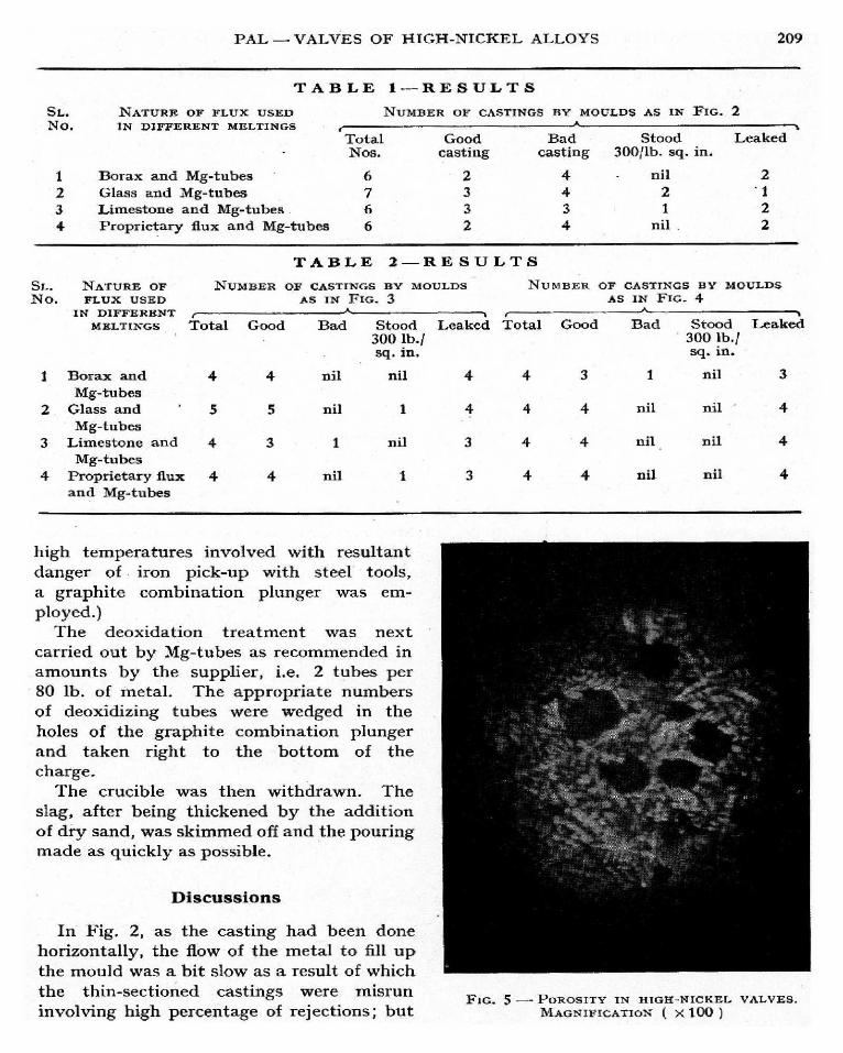
FIG. 4-POSITION OF THE PATTERN IN THE
MOULD-BOX. BOXES CAST VERTICALLY AT AN
ANGLE OF 70'
-rWNWM""W"
PAL - VALVES OF HIGH-NICKEL ALLOYS 209
TABLE
SL.
NONATURE OF 'FLUX USED
ERENT MELTIIN DI GS. NFF
TotalNos.
1 Borax and Mg-tubes 62 Glass and Mg-tubes 73 Limestone and Mg-tubes 6
4 Proprietary flux and Mg-tubes 6
SL. NATURE OF NUMBER
No. FLUX USED
1---RESULTS
NUMBER OF CASTINGS BY MOULDS AS IN FIG. 2
Goodcasting
233
2
TABLE 2-RESULTS
Bad Stood Leakedcasting 30011b . sq. in.
4 - nil 2
4 2 13 1 24 nil 2
OF CASTINGS BY MOULDS NUMBER OF CASTINGS BY MOULDS
AS IN FIG . 3 As IN FI(:;. 4
I
IN DIFFERENTMELTINGS
Borax and
r--Total
4
Good
4
Bad
nil
2
Mg-tubesGlass and 5 5 nil
3Mg-tubes
Limestone and 4 3 1
4Mg-tubes
Proprietary flux 4 4 niland Mg-tubes
Stood Leaked Total Good Bad Stood Leaked300 lb. 1 300 lb./sq. in . sq. in.
high temperatures involved with resultantdanger of iron pick-up with steel tools,
a graphite combination plunger was em-ployed.)
The deoxidation treatment was nextcarried out by Mg-tubes as recommended inamounts by the supplier, i.e. 2 tubes per80 lb. of metal. The appropriate numbersof deoxidizing tubes were wedged in theholes of the graphite combination plungerand taken right to the bottom of thecharge.
The crucible was then withdrawn. Theslag, after being thickened by the additionof dry sand, was skimmed off and the pouringmade as quickly as possible.
Discussions
In Fig. 2, as the casting had been donehorizontally, the flow of the metal to fill upthe mould was a bit slow as a result of which
the thin-sectioned castings were misruninvolving high percentage of rejections; but
4 4 3 1 nil 3
4 4 4 nil nil 4
3 4 4 nil nil 4
3 4 4 nil nil 4
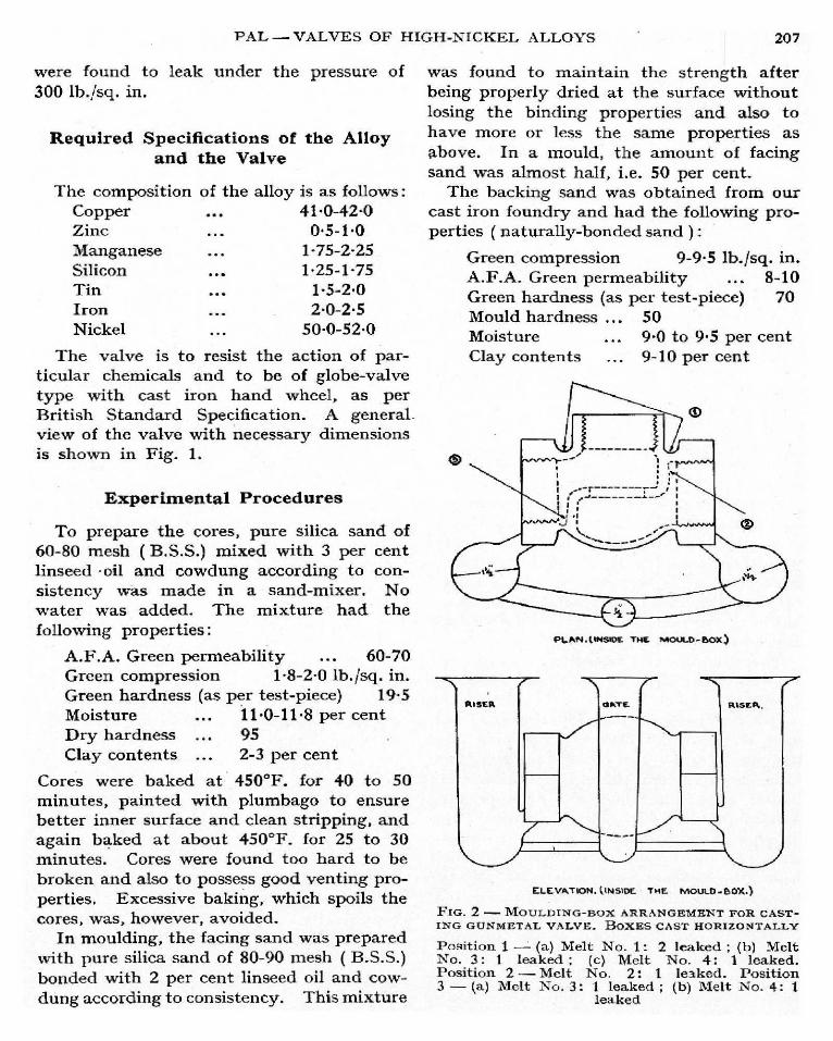
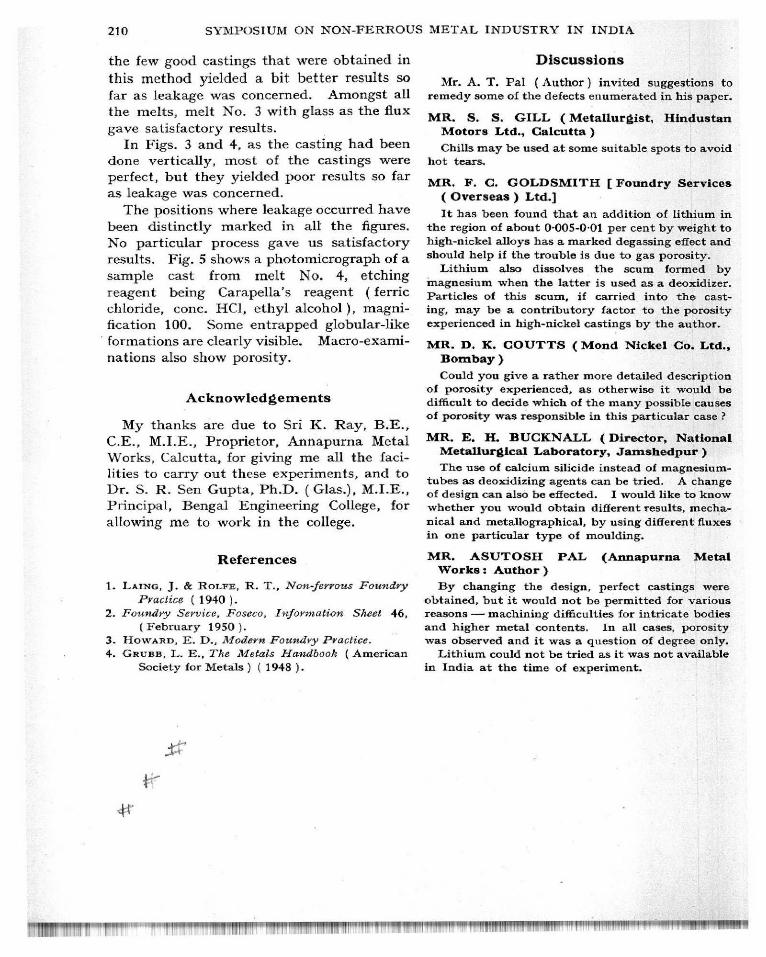
FIG. 5 -POROSITY IN HIGH-NICKEL VALVES.
MAGNIFICATION ( X100)
210 SYMPOSIUM ON NON-FERROUS METAL INDUSTRY IN INDIA
the few good castings that were obtained in
this method yielded a bit better results so
far as leakage was concerned. Amongst allthe melts, melt No. 3 with glass as the flux
gave satisfactory results.In Figs. 3 and 4, as the casting had been
done vertically, most of the castings wereperfect, but they yielded poor results so far
as leakage was concerned.
The positions where leakage occurred havebeen distinctly marked in all the figures.No particular process gave us satisfactory
results. Fig. 5 shows a photomicrograph of asample cast from melt No. 4, etching
reagent being Carapella's reagent (ferricchloride, cone. HCl, ethyl alcohol), magni-fication 100. Some entrapped globular-likeformations are clearly visible. Macro-exami-
nations also show porosity.
Acknowledgements
My thanks are due to Sri K. Ray, B.E.,
C.E., M.I.E., Proprietor, Annapurna MetalWorks, Calcutta, for giving me all the faci-lities to carry out these experiments, and toDr. S. R. Sen Gupta, Ph.D. (Glas.), M.I.E.,Principal, Bengal Engineering College, for
allowing me to work in the college.
References
1. LAING , J. & ROLFE, R. T., Non ferrous Foundry
Practice (1940 ).2. Foundry Service, Foseco, Information Sheet 46,
( February 1950).3. HOWARD , E. D., Modern Foundry Practice.4. Gaups, L. E., The Metals Handbook ( American
Society for Metals ) ( 1948 ).
Discussions
Mr. A. T. Pal (Author) invited suggestions toremedy some of the defects enumerated in his paper.
MR. S. S . GILL ( Metallurgist , HindustanMotors Ltd., Calcutta )
Chills may be used at some suitable spots to avoidhot tears.
MR. F. C. GOLDSMITH [ Foundry Services( Overseas) Ltd.]
It has been found that an addition of lithium inthe region of about 0.005 -0.01 per cent by weight tohigh-nickel alloys has a marked degassing effect andshould help if the trouble is due to gas porosity.
Lithium also dissolves the scum formed by
magnesium when the latter is used as a deoxidizer.
Particles of this scum, if carried into the cast-
ing, may be a contributory factor to the porosity
experienced in high-nickel castings by the author.
MR. D. K. COUTTS ( Mond Nickel Co. Ltd.,Bombay)
Could you give a rather more detailed descriptionof porosity experienced , as otherwise it would bedifficult to decide which of the many possible causes
of porosity was responsible in this particular case ?
MR. E. H. BUCKNALL ( Director, National
Metallurgical Laboratory, Jamshedpur)
The use of calcium silicide instead of magnesium-tubes as deoxidizing agents can be tried . A changeof design can also be effected . I would like to knowwhether you would obtain different results , mecha-nical and metallographical , by using different fluxesin one particular type of moulding.
MR. ASUTOSH PAL (Annapurna MetalWorks : Author)
By changing the design , perfect castings were
obtained , but it would not be permitted for variousreasons - machining difficulties for intricate bodies
and higher metal contents . In all cases , porosity
was observed and it was a question of degree only.Lithium could not be tried as it was not available
in India at the time of experiment.
l