Embed Size (px)
Citation preview

Engineering GREAT Solutions
Valves and Solutions for Power Plants

Engineering GREAT Solutions
Valves and Systems for Power Plants
03 Valves and Solutions Introduction
04 Valves and Solutions Overview
05 Safety Valves
12 Safety Shut Off Valves
16 Control Valves
21 Shut Off Valves
24 Measurement & Control
Contents
2

3
Valves and Solutions IntroductionIMI Bopp & Reuther safety, shut o� and control valves can be found wherever there is a need to safeguard or precisely control the operating conditions in steam and water systems. Operators and engineers from all sectors of the power plant industry benefit from our experience and process expertise.
Today IMI Bopp & Reuther is a recognised and approved manufacturer of safety, shut o� and control valves as well as a complete system solutions provider for all types of power plants:
• Coal Fired Power Plants
• Combined Cycle Power Plants
• Industrial Power Plants
• Combined Heat and Power Plants
• Desalination Plants
• Biopower Plants
• Cogeneration Power Plants
We develop and deliver individual solutions matched to our customer requirements and specifications for all of these technologies. A primary focus is our attention and dedication to constantly improve our products and services for our customers and the industry as a whole.
We also strive to continuously review and expand our product range to best suit the customer’s demands for packages and complete systems.
There are many reasons for choosing IMI Bopp & Reuther:
• The latest developments in technology and materials are considered from design through to manufacturing and quality control.
• We operate one of the most modern and efficient valve testing facilities in the world.
• Our core competence in welding and heat treatment of alloy steels is highly respected and a benchmark in the industry.
• IMI Bopp & Reuther after sales service for all products supplied and engineered and associated equipment is paramount to our customers and operators overall satisfaction. We have bundled our resources together with all the companies in the IMI Bopp & Reuther Group to provide the best possible service.
IMI Bopp & Reuther has built up a reputation as a specialist for valves and solutions in the power plant industry. A wide range of well known and respected customers rely on our knowledge and experience and benefit from our wide range of products.
Please do not hesitate to contact us with your requirements and we will do our utmost to ensure the optimum solution for you.
Wide range of valve types, sizes and materials
High functional realibity for safe and efficient plant protection

Valves and Systems for Power Plants
4
Valves and Systems Overview
IMI Bopp & Reuther Valves and Systems are designed to protect the environment and human life. We have great application experience in severe service and our continuous interaction with our customers makes us ideally positioned to provide the optimum products and solutions.
IMI Bopp & Reuther develops, designs, labels, manufactures and supplies safety valves in accordance with common approvals and standards, which can be found in the detailed product description.
Safety valvesSafety valves have the function of preventing inadmissible overpressure in pipe systems, pressure vessel and boilers, in order to avoid danger to people, plant and the environment. This application category includes spring loaded, pneumatic assisted and hydraulic operated safety valves.
Safety Shut O� ValvesThis application category includes steam conditioning or pressure reducing valve with integrated fail safe close function and safety shut o� valves.
Control ValvesIMI Bopp & Reuther control valves are used to provide modulating control in emergency cooling systems of power plants.
Shut O� ValvesIn the category shut off valves the HP Cross-, Stop- and Preheater Bypass Valves are used for isolating steam.
Measurement & ControlThis category includes pneumatic and hydraulic control units. Control valves are used to provide modulating control in emergency cooling systems of power plants.

SiZ 2507The Main Steam Safety Valve SiZ 2507 is designed according to ASME requirements and in usage in all power plants. Safety valve for main boiler and reheater protection. - Pneumatic actuated
SiR 2507Control Valve to bleed o� excess steam within the reheater system for fast load changes. Safety valve for main boiler and reheater protection. - Hydraulic actuated
5
The safety valves program o�ers a great number of types and sizes, material designs and an extensive range of connections. Flange, welded, threaded and clamp-type connections can be selected to suit the pressure system. Special connections are easy to provide if requested by the customer.
These safety valves are being used in di�erent power plants worldwide. They are designed for high performance applications and open/close very quickly to reduce steam loss to a minimum.
Safety Valves

SiRA BHLHigh Pressure Turbine Bypass for start up, shut down or turbine trip.
SiRA BHTHigh Pressure Turbine bypass for start up, shut down or turbine trip and is also available without safety function as HP Turbine Bypass.
SiRA BHsTSafety Valve for safeguarding high pressure systems and is applicable for low noise requirements.
Valves and Systems for Power Plants
6
Safety Valves

7
SiZ 2507
Sizes DN 50 to DN 900 2" to 36"
Set pressures max. 330 bar
Materials
1.0460 / 1.0619 SA 105 / SA 216 Gr. WCB
1.7335 / 1.7357 SA 182 Gr. F12 (F11)
SA 217 Gr. WC 6
1.7383 / 1.7379 SA 182 Gr. F22
SA 217 Gr. WC 9
1.4903 SA 182 Gr. F91
SA 217 Gr. C 12A
1.4901 SA 182 Gr. F92
Additional materials on request
Benefits and featuresThe SiZ 2507 is a flow-to-open design valve with a forged or casted body. Usually connected to the main steam line or to the re-heater lines, it is opened when the pressure overcomes the pre-set force of the Belleville Spring pack or, if equipped with a pneumatic actuator, when the loading air in the actuator is thrown o� relieving the spring from the force added by the actuator. Depending on the control cabinet used to control the assisting air then air to help lift the plug can also be applied. The valve's parabolic plug will then open to the required lift position and vent the steam into the atmosphere relieving the excess pressure from the steam line until a safe level is reached and the valve can be closed again by the force of the Belleville Spring and/or pneumatic assistance.
For applications in coal fired power plants, combined cycle power plants, industrial power plants, other steam boiler applications and/or turbine bypass applications.
The Safety Relief Valve SiZ is generally used to safeguard the main steam and re-heater systems of power plants. It can be used as a controlled safety valve or as a standard spring loaded safety valve with the pneumatic actuator removed.
Upper valve can be blocked and removed avoiding re-setting the valve after inspection
IMI Bopp & Reuther does possess the technology to perform high quality body seat repair.
Belleville Spring
Integrated Air Piston
Blocking Device for Easy Maintenance
Full Nozzle Design
Pneumatic actuated reheater safety valve combined with a control system to realize control application as a safety valve

Valves and Systems for Power Plants
8
SiR 2507
Sizes DN 50 to DN 900 2" to 36"
Set pressures max. 330 bar
Materials
1.7335 SA 182 Gr. F12
1.7383 SA 182 Gr. F22
1.4903 SA 182 Gr. F91
1.4901 SA 182 Gr. F92
Additional materials on request
Benefits and featuresThe SiR 2507 is a flow-to-open design valve with a forged body. Usually connected to the main steam line or to the re-heater lines it is activated when the pressure exceeds a pre-determined level. The valve's parabolic plug will then be retracted by the hydraulic actuator (assisted by a helical spring inside the actuator) in the shortest time possible, enabling the steam to be vented into the atmosphere releasing the excess pressure from the steam line until a safe level is reached and the valve can be closed again.
For applications in coal fired power plants, combined cycle power plants,industrial power plants, other steam boiler applications and / or turbine bypass applications.
The Hydraulically Actuated Safety Valve SiR is generally used to safeguard the main steam and re-heater systems of power plants. Besides the safeguarding it can also be used during start-up to match start-up curves.
Reheater safety valve with high grade material applications
Hydraulic actuated reheater safety valve combined with a control system to realize control application as a safety valve.
Outdoor installation of IMI B&R reheater safety valves
Pinpoint accuracy
User friendly setup
Powerful actuator
Sturdy valve body
Customised inlet and outlet

9
SIRA BHL
Sizes DN 100 to DN 800 4" to 32"
Set pressures max. 330 bar
Materials
1.7335 SA 182 Gr. F12
1.7383 SA 182 Gr. F22
1.4903 SA 182 Gr. F91
1.4901 SA 182 Gr. F92
Additional materials on request
Benefits and featuresThe pressure reduction in the SIRA BHL valve is accomplished using multiple controlled and uncontrolled pressure reducing stages. The perforated plug accurately regulates the flow of steam through the valve. The de-superheating water is injected via a drilled stem into the valve body. The multiple stages facilitate a good noise reduction during operation.
The valve seat is replaceable and hard faced for added durability and a long, trouble free life.
The spray water injection point is right behind the seat in the most turbulent zone of the steam flow. This ensures the shortest possible evaporation length and therefore results in a reduction of the straight pipe requirement downstream of the valve. The hydraulic actuator with adapted Instrumentation & Control components provides powerful, accurate positioning and control and feedback.
For applications in coal fired power plants, combined cycle power plants, industrial power plants, other steam boiler applications and/or turbine bypass applications.
A high pressure turbine bypass valve is used to divert some or all of the steam flowing from the main boiler away from the turbine and into the cold reheater line. The valve reduces both the pressure and temperature so the steam can be safely transferred between these two systems.
Straight forward design for easy assembly
Process scheme of conventional thermal power plant with HP-Bypass station type SIRA (integrated safety-function according TRD 421)
Pinpoint positioning accuracy
Compact design with inbody injection
Excellent spray water atomisation
Powerful hydraulic actuator
Customised inlet and outlet
Hydraulic actuated safety valve with stem injection with stem vertical installation; other installation positions on request

Valves and Systems for Power Plants
10
SIRA BHT
Sizes DN 100 to DN 800 4" to 32"
Set pressures max. 330 bar
Materials
1.7335 SA 182 Gr.F12 (F11)
1.7383 SA 182 Gr.F22
1.4903 SA 182 Gr.F91
1.4901 SA 182 Gr.F92
Additional materials on request
Benefits and featuresThis valve series is usable for reducing steam pressure and temperature, also for high pressure turbine bypass for startup, shut down or turbine trip.
SIRA BHT is available without safety function as HP Turbine Bypass.
For applications in coal fired power plants, combined cycle power plants, industrial power plants, other steam boiler applications and/or turbine bypass applications
The modern SIRA BHT Hydraulic operated safety valve for all regular capacity applications in all process industries sectors.
Turbine bypass valve with integrated safety function for every customer spe-cification
Hydraulic actuated safety valve with central steam atomising injection in the valve outlet with a very high accuracy
Powerful hydraulic actuator
Steam atomising injection in the valve outlet
Pinpoint positioning accuracy
Compact valve body design Customised
inlet and outlet

11
Pinpoint positioning accuracy
Low noise pressure reduction
Excellent spray water atomisation
Powerful hydraulic actuator
Customised inlet and outlet
SIRA BHsT
Sizes DN 100 to 800 4" to 32"
Set pressures max. 330 bar
Materials
1.7335 SA 182 Gr.F12 (F11)
1.7383 SA 182 Gr.F22
1.4903 SA 182 Gr.F91
1.4901 SA 182 Gr.F92
Additional Materials on request
Benefits and featuresThe pressure reduction in the SIRA BHsT valve is accomplished using multiple con-trolled and uncontrolled pressure reducing stages. The plug accurately regulates the flow of steam through the valve. When the valve initially opens, some of the steam is also diverted through an integral pipe to the steam atomising injection nozzle.
The multiple stages prevent excessive noise generation during operation.
The valve seat is integrated in the body and hard faced for added durability and a long, trouble free life. The steam atomising nozzle is centrally arranged in the valve outlet and nozzle can easily be removed for maintenance. The steam atomising in-jection is designed to reduce the size of the water droplets. This increases their sur-face area improving vaporisation and ultimately reduces the overall time to reach the target temperature. The hydraulic actuator with adapted instrumentation & control components provides powerful, accurate positioning and control and feedback.
For applications in coal fired power plants,combined cycle power plants, industrial power plants, other steam boiler applications and / or turbine bypass applications.
A high pressure turbine bypass valve is used to divert some or all of the steam flowing from the main boiler away from the turbine and into the cold reheater line. The valve reduces both the pressure and temperature so the steam can be safely transferred between these two systems.
HP Bypass stations with a worldwide in-stallation basis and a good reputation. It supports the efficiency of the Power Plants.
Easy assembly and reassembly of the valve for better maintenance
Sophisticated plug design for outstanding controllability

Valves and Systems for Power Plants
12
Safety Shut O� Valves
Safety shut o� valves can be found in industrial, coal fired, combined cycle, combined heat and cogeneration power plants.
In all solutions we have a Strainer in the inlet of the safety shut o� valve.
The variety of pressure ratings, temperature classes and sizes provides a flexible choice for all industrial requirements.
DDESteam Conditioning Valve with integrated Fail Safe Close Function for reducing steam pressure and temperature.
DS Quick Stop Valve to protect down-stream piping systems from over pressure and / or temperature.
DBPressure Reducing Valve with integrated Fail Safe Close Function for reducing steam pressure.

13
Powerful actuator
Water injection either via the stem or nozzles in the outlet
Pinpoint accuracy
Customised inlet and outlet
DDE
Sizes DN 100 to 1800 4" to 32"
Set pressures max. 330 bar
Materials
1.0460 / 1.0619 SA 105 / SA 216 Gr. WCB
1.5415 SA 182 Gr. F1
1.7335 / 1.7357 SA 182 Gr. F12 (F11) SA 217 Gr. WC 6
1.7383 / 1.7379 SA 182 Gr. F22 SA 217 Gr. WC 9
1.4903 SA 182 Gr. F91 SA 217 Gr. C 12A
1.4901 SA 182 Gr. F92
Additional materials on request
Benefits and featuresThe valve works as a bypass valve to reduce the temperature and the pressure of an upstream system to the downstream system.
In addition to the valve body, the valve is comprised of an actuator and an injection.
The steam conditioning valve is a valve in which the steam flow is in the closing direction. Thus, the steam flow has a closing effect on the valve plug. Depending on construction the valve body consists of heat resistant forged steel or cast iron.
For applications in coal fired power plants, combined cycle power plants, industrial power plants, other steam boiler applications and / or turbine bypass applications.
The Safety Shut O� Valve Type DDE with integrated fail safe close function is for boiler start up and shut down as well as safeguarding the downstream piping systems against over pressure and/or high temperatures.
It can provide exact pressure and temperature control in downstream piping systems.
IMI Bopp & Reuther operates 2 steam test benches for hot setting of steam safety valves
IMI Bopp & Reuther has a range of four di�erent steam atomising nozzle sizes to cover a wide range of applications
Find solutions for different sizes and ma-terials

Valves and Systems for Power Plants
14
Powerful actuator
Tight closed
Pinpoint accuracy
Customised inlet and outlet
DB
Sizes DN 50 to 2000 4" to 80"
Set pressures max. 330 bar
Materials
1.0460 / 1.0619 SA 105 / SA 216 Gr. WCB
1.5415 SA 182 Gr. F1
1.7335 / 1.7357 SA 182 Gr. F12 (F11) SA 217 Gr. WC 6
1.7383 / 1.7379 SA 182 Gr. F22 SA 217 Gr. WC 9
1.4903 SA 182 Gr. F91 SA 217 Gr. C 12A
1.4901 SA 182 Gr. F92
Additional materials on request
Benefits and featuresThe valve works as a bypass valve to reduce the pressure of an upstream system to the downstream system.
The hydraulic actuator supports steam conditioning process without temperature control. Furthermore the actuator is able to ensure a pinpoint accuracy in any regu-lating postion.
For applications in coal fired power plants, combined cycle power plants, industrial power plants, other steam boiler applications and / or turbine bypass applications.
The Safety Shut O� Valve Type DB reduces steam pressure and provides auxiliary steam with an integrated safety function.
For coal fired, industrial, combined heat and cogeneration power plants.
Engineering know-how coupled with experience is what it takes to be a Valve Doctor®. The Valve Doctor® team will solve your plant problems.
Hydraulic actuated safety shut off valve with a regulating function but without desuperheating
Very common in combined cycle power plants

15
DS
Powerful actuator
Tight closed
Pinpoint accuracy
Customised inlet and outlet
Sizes DN 50 to 700 2" to 28"
Set pressures max. 330 bar
Materials
1.0460 / 1.0619 SA 105 / SA 216 Gr. WCB
1.5415 SA 182 Gr. F1
1.7335 / 1.7357 SA 182 Gr. F12 (F11) SA 217 Gr. WC 6
1.7383 / 1.7379 SA 182 Gr. F22 SA 217 Gr. WC 9
1.6368 (WB36)
1.4903 SA 182 Gr. F91 SA 217 Gr. C12A
1.4901 SA 182 Gr. F92
Additional materials on request
Benefits and featuresDifferent material designs are available for high as well as low temperatures.
Quick Stop Valve to protect downstream piping systems from over pressure and/or temperature.
Typical applications are the protection of system components, steam boiler, air separator, power plants and industrial steam generation.
The Safety Shut O� Valve Type DS is a high-pressure safety valve and has a reliable high quality design with solid inlet nozzle, screwed in and welded, available in various sizes and options.
Well educated engineers can support customers all over the world
Safety Shut Off Valve Type DS for isolating downstream steam systems
This valve can be found in several coal fired-industrial – and combined heat power plants
DB
Valves and Systems for Power Plants
16
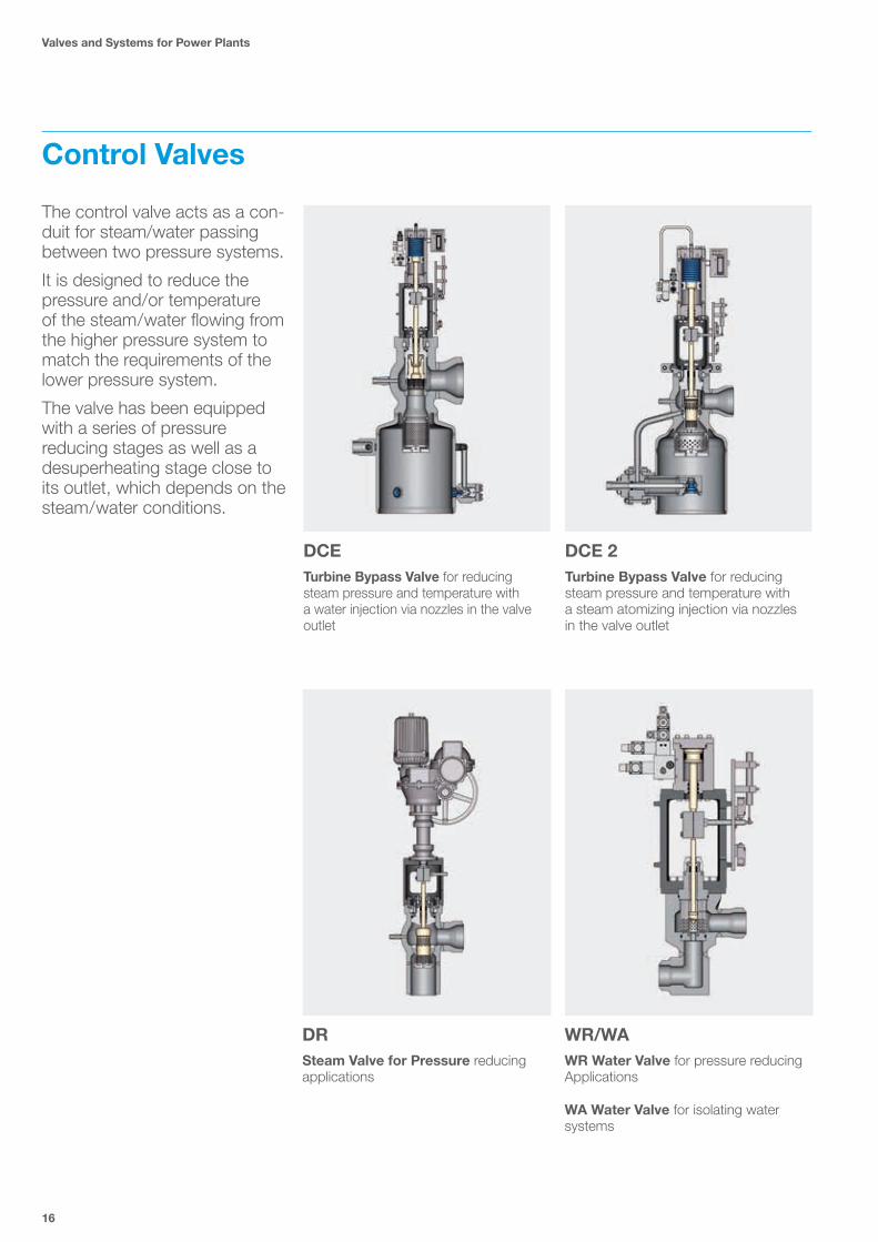
Control Valves
The control valve acts as a con-duit for steam/water passing between two pressure systems.
It is designed to reduce the pressure and/or temperature of the steam/water flowing from the higher pressure system to match the requirements of the lower pressure system.
The valve has been equipped with a series of pressure reducing stages as well as a desuperheating stage close to its outlet, which depends on the steam/water conditions.
DCETurbine Bypass Valve for reducing steam pressure and temperature with a water injection via nozzles in the valve outlet
DRSteam Valve for Pressure reducing applications
WR/WAWR Water Valve for pressure reducing Applications
WA Water Valve for isolating water systems
DCE 2Turbine Bypass Valve for reducing steam pressure and temperature with a steam atomizing injection via nozzles in the valve outlet

Compact and robust design for best performance according to customer spe-cification
17
DCE
Pressure seal /flange bonnet
Plug / Cage
Spray water nozzle
Pressure reducing stages
Sizes DN 50 to 2000 2" to 80"
Set pressures max. 330 bar
Materials
1.0460 / 1.0619 SA 105 / SA 216 Gr. WCB
1.5415 SA 182 Gr. F1
1.7335 / 1.7357 SA 182 Gr. F12 (F11) SA 217 Gr. WC 6
1.7383 / 1.7379 SA 182 Gr. F22 SA 217 Gr. WC 9
1.6368 (WB36)
1.4903 SA 182 Gr. F91 SA 217 Gr. C12A
1.4901 SA 182 Gr. F92
Additional materials on request
Benefits and featuresThe valve works as a bypass valve to reduce the temperature and the pressure of an upstream system to the downstream system.
The steam conditioning valve is a valve in which the water flow is in the closing direction. Thus, the steam flow has a closing effect to the valve plug. Depending on construction the valve body consists of heat resistant forged steel or cast iron.
Different material designs are available for high as well as low temperatures.
For applications in coal fired power plants, combined cycle power plants and industrial power plants.
Turbine bypass valve for low, medium and high pressure applications. HP pressure turbine bypass for boiler start up / shut down and turbine trip IP/LP for safeguarding the condenser against excessive pressures and/or temperatures.
Turbine bypass valve with spray water injection

Valves and Systems for Power Plants
18
DCE 2
Steam atomising nozzle
Powerful pneumatic actuator
Special designed cage
Sizes DN 50 to 2000 2" to 80"
Set pressures max. 330 bar
Materials
1.0460 / 1.0619 SA 105 / SA 216 Gr. WCB
1.5415 SA 182 Gr. F1
1.7335 / 1.7357 SA 182 Gr. F12 (F11) SA 217 Gr. WC 6
1.7383 / 1.7379 SA 182 Gr. F22 SA 217 Gr. WC 9
1.6368 (WB36)
1.4903 SA 182 Gr. F91 SA 217 Gr. C12A
1.4901 SA 182 Gr. F92
Additional materials on request
Benefits and featuresDCE 2 features multiple pressure reduction stages in the valve body as well as in the outlet of valve. Its design fits to specified process conditions from the customer.
Thanks to the steam atomizing injection, injecting water droplets for desuperheating can be reduced at minimum size to ensure the accuracy of temperature control to reach the downstream piping system condition.
The steam conditioning valve DCE 2 is customized for each specific application.
For applications in coal fired power plants, combined cycle power plants, industrial power plants.
DCE 2 Steam Conditioning Valve for reducing steam and temperature applica-tions. Turbine Bypass for boiler start up / shut down and turbine trip.
World leading test capabilities
Steam conditioning valve with steam atomising injection

19
DR
Sectional drawing with hydraulic actuator
Self-supporting yoke
Powerful electrical actuator
Inlet size according to customer request
Sizes DN 50 to 2000 2" to 80"
Set pressures acc. request
Materials
1.0460 / 1.0619 SA 105 / SA 216 Gr. WCB
1.5415 SA 182 Gr. F1
1.7335 / 1.7357 SA 182 Gr. F12 (F11) SA 217 Gr. WC 6
1.7383 / 1.7379 SA 182 Gr. F22 SA 217 Gr. WC 9
1.6368 (WB36)
1.4903 SA 182 Gr. F91 SA 217 Gr. C12A
1.4901 SA 182 Gr. F92
Additional materials on request
Benefits and featuresDifferent material designs are available for high as well as low temperatures.
The main purpose of the valve is to reduce steam pressure and it can operate in high Temperature (max. 630 °C) applications.
For applications in coal fired power plants, combined cycle power plants, industrial power plants, combined heat and power plants, cogeneration power plants.
The DR Pressure Reducing Valve is used to reduce the pressure of an upstream sys-tem to a downstream system.
The pressure reducing valve is a valve where the valve plug is flowed in the closing direction. Thus, the steam flow has a closing effect to the valve plug. Depending on construction the valve body consists of heat resistant forged steel or cast iron.
Reducing steam pressure valve with a hydraulic actuator also available for pneu-matic or electrical actuated solutions
IMI Bopp & Reuther has the technology to perform high quality body seat repairs
Valves and Systems for Power Plants
20
WR/WA
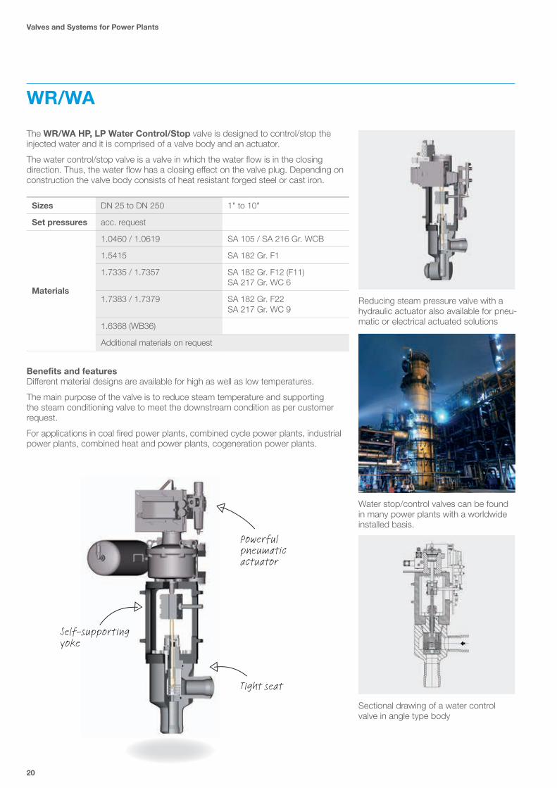
Water stop/control valves can be found in many power plants with a worldwide installed basis.
Self-supporting yoke
Powerful pneumatic actuator
Tight seat
Sizes DN 25 to DN 250 1" to 10"
Set pressures acc. request
Materials
1.0460 / 1.0619 SA 105 / SA 216 Gr. WCB
1.5415 SA 182 Gr. F1
1.7335 / 1.7357 SA 182 Gr. F12 (F11) SA 217 Gr. WC 6
1.7383 / 1.7379 SA 182 Gr. F22 SA 217 Gr. WC 9
1.6368 (WB36)
Additional materials on request
Benefits and featuresDifferent material designs are available for high as well as low temperatures.
The main purpose of the valve is to reduce steam temperature and supporting the steam conditioning valve to meet the downstream condition as per customer request.
For applications in coal fired power plants, combined cycle power plants, industrial power plants, combined heat and power plants, cogeneration power plants.
The WR/WA HP, LP Water Control/Stop valve is designed to control/stop the injected water and it is comprised of a valve body and an actuator.
The water control/stop valve is a valve in which the water flow is in the closing direction. Thus, the water flow has a closing effect on the valve plug. Depending on construction the valve body consists of heat resistant forged steel or cast iron.
Reducing steam pressure valve with a hydraulic actuator also available for pneu-matic or electrical actuated solutions
Sectional drawing of a water control valve in angle type body
21
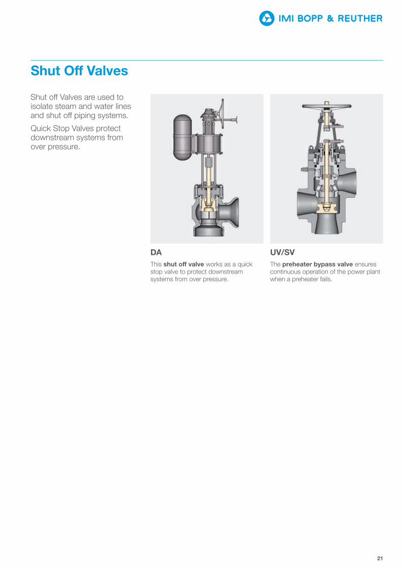
Shut O� Valves
Shut o� Valves are used to isolate steam and water lines and shut o� piping systems.
Quick Stop Valves protect downstream systems from over pressure.
DAThis shut o� valve works as a quick stop valve to protect downstream systems from over pressure.
UV/SVThe preheater bypass valve ensures continuous operation of the power plant when a preheater fails.

Valves and Systems for Power Plants
22
DA
Water stop/control valves can be found in many power plants with a worldwide installed basis.
Optimized body
Powerful hydraulic actuator with helical spring
Strainer in front of the seat
Sizes DN 50 to 700 2" to 28"
Set pressures acc. request
Materials
1.0460 / 1.0619 SA 105 / SA 216 Gr. WCB
1.5415 SA 182 Gr. F1
1.7335 / 1.7357 SA 182 Gr. F12 (F11) SA 217 Gr. WC 6
1.7383 / 1.7379 SA 182 Gr. F22 SA 217 Gr. WC 9
1.4903 SA 182 Gr. F91 SA 217 Gr. C12A
1.4901 SA 182 Gr. F92
Additional materials on request
Benefits and featuresThe Shut Off Valve Type DA works as a Quick Stop Valve to protect downstream systems from over pressure.
For applications in coal fired power plants, combined cycle power plants, industrial power plants, combined heat and power plants, cogeneration power plants and other facilities with the need to shut o� piping systems.
The DA Shut O� Valve is used to stop the steam between an upstream system and a downstream system. The valve is comprised of a valve body and an actuator. The steam stop valve is a valve in which the steam flow is in the closing direction. Thus, the steam flow has a closing effect on the valve plug. Depending on construc-tion the valve body consists of heat resistant forged steel or cast iron.
Shut o� Valve with pneumatic Actuator is a very common solution for our customers worldwide
We combine our decades of experience and knowledge to satisfy the demands that our customer place on us.

6
7 8
9
1 2
3 4
5
23
UV/SV
Feedwater powered
Streamline interior forreduced pressure drop Straight through
bypass
Sizes DN 50 to 2000 4" to 22"
Set pressures acc. request
Materials
1.0460 / 1.0619 SA 105 / SA 216 Gr. WCB
1.5415 SA 182 Gr. F1
1.6368 (WB36)
Additional materials on request
Benefits and featuresIn thermal power generation the feedwater heater uses heat transfer from extraction steam to the feedwater pre-heating it, improving overall plant efficiency.
In case of a feedwater heater malfunction, it needs to be isolated using a bypass system to allow maintenance without disrupting the flow of feedwater to the boiler.
The three big benefits are: protects feedwater heater steam jacket against tube rup-ture or leakage, protects turbine extraction from excessive backpressure and allows bypass of feedwater heater during peak loads to increase power output from the turbine.
For applications in coal fired power plants, combined cycle power plants, industrial power plants and other preheating systems in boiler feed water circuits.
To improve the efficiency of a steam generator, water is pressurized and pre-heated before being fed into the boiler. The heat exchangers in this feed water system need to be protected in case there is a rupture between the steam heating pipes and the water circulation, such a rupture would severely damage downstream equipment including the turbines. The preheater is protected by a bypass system that diverts the feed water around the heat exchanger in the event of a problem thus protecting the entire system.
Preheater bypass valve with hand wheel to return to normal position
Part Description
1 Handwheel
2 Yoke
3 Pressure Seal / Upper Actuator Chamber
4 Connecting Stud for Quick Acting On/O� Valve
4 Actuator Lower Chamber / PR Stage
6 Piston Area
7 Stem w. Plug
8 Valve Body
9 Seat
Self-actuated with manual reset

Valves and Systems for Power Plants
24
Measurement & Control
IMI Bopp & Reuther can supply di�erent solutions to control and measure pressure and flow upon request.
Control units are used to control the flow and direction to the various sections of the safety valve piston to keep the valve shut tight before the set pres-sure is reached, and when the set pressure is reached, it is directed to assist opening the valve.
The measuring and testing unit helps to activate and inspect the safety function at the safety control valves with pneumatic or hydraulic actuators.
Control Unit PC 50The “Control Unit” PC 50 is designed for operation of pneumatic assisted safety valves.
EPC 54/55 Electro Pneumatic Control Units To control assisted safety valves (spring loaded safety valves with additional pneumatic piston)
MT 5356Safety function cabinet for pneumatically or hydraulically assisted safety valves
Pneumatic Control Unit PC 51The operation limits of spring loaded safety valves can be improved by use of pneumatic control

25
HSSHydraulic Supply Unit for hydraulically actuated valves
HCS/PCS Control of hydraulic supply unitsPositioning of hydraulically assisted control valves or bypass systems (PCS)

Valves and Systems for Power Plants
26
PC 50
Control Unit PC 50 controls safety valves with piston and lifting device.
Triple redundancy
Stable performanceState-of-the-art
components
Highest reliability
Excellent system integrity PC 50 control unit with connected
pneumatic assisted spring loaded safety relief valve
Mounting position
The function of the pneumatic control unit PC50 is to control spring loaded safety valves with a pneumatic actuator for loading and lifting air.
The control unit operates in accordance with the closed circuit principle with the external medium being air.
This product is suitable for gases, steam or liquids, for applications in chemical and petrochemical industries, in process industries, power generation, in conjunction with assisted safety valves as well as for nuclear applications.
Benefits and featuresPC 50 is suitable for wide application area, for gases, steam or liquids. The triple redundant pressure measuring ensures the pipe line system safety and the pressure switches can be checked during the power plant operation stage to realize non-stope maintenance and any-time safety check.
For applications in coal fired power plants, combined cycle power plants, industrial power plants, other steam boiler applications and/or turbine bypass applications.
Limit of supply
Fixture on site
Pressure tapping (water seal)

27
PC 51
Outside view of PC51; Regulating the functions of the safety valve
Reduced hysteresis +3% | -4% possible
Sealing up to set pressure
Protect people and environment in the area surrounding critical situation
Inside view of PC51; Triple redundancy pressure switches with locking rail
The function of the pneumatic control unit PC 51 is to control spring loaded safety valves with a pneumatic actuator for loading and lifting air
The control unit operates in accordance with the closed circuit principle with the external medium being air. The safety valves operate in accordance with the relieving principle.
Benefits and featuresPC 51 is for controlling spring loaded safety valves equipped with pneumatic actuators. The control unit works in accordance with the closed circuit principle with the external medium to assist safety valve regulating function. PC51 can be operated for two valves in the same time. The triple redundant pressure measuring ensures the pipe line system safety and the pressure switches can be checked during the power plant operation stage to for continuous maintenance and safety checks at any time.
For applications in coal fired power plants, combined cycle power plants, industrial power plants, other steam boiler applications and/or turbine bypass applications
Valves and Systems for Power Plants
28
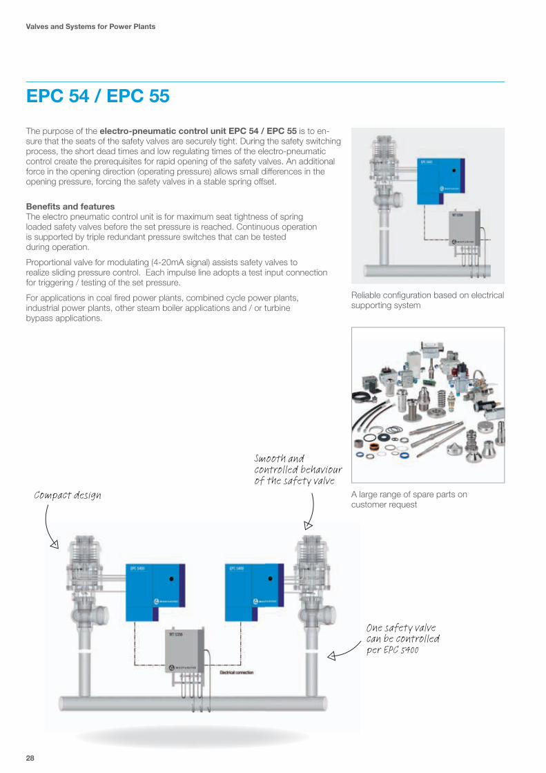
EPC 54 / EPC 55
Reliable configuration based on electrical supporting system
A large range of spare parts on customer request
Compact design
Smooth and controlled behaviour of the safety valve
One safety valve can be controlled per EPC 5400
The purpose of the electro-pneumatic control unit EPC 54 / EPC 55 is to en-sure that the seats of the safety valves are securely tight. During the safety switching process, the short dead times and low regulating times of the electro-pneumatic control create the prerequisites for rapid opening of the safety valves. An additional force in the opening direction (operating pressure) allows small differences in the opening pressure, forcing the safety valves in a stable spring o�set.
Benefits and featuresThe electro pneumatic control unit is for maximum seat tightness of spring loaded safety valves before the set pressure is reached. Continuous operation is supported by triple redundant pressure switches that can be tested during operation.
Proportional valve for modulating (4-20mA signal) assists safety valves to realize sliding pressure control. Each impulse line adopts a test input connection for triggering / testing of the set pressure.
For applications in coal fired power plants, combined cycle power plants, industrial power plants, other steam boiler applications and / or turbine bypass applications.

29
MT 5356
Many of our safety, shut o� and control valves are still in operation after decades of reliable operation. We undertake regu-lar maintenance as well as expert refur-bishment and repairs on your behalf
MT 5356 in configuration with safety con-trol valves
Triple redundant safety control circuits
Up to four safety valves can be controlled
The DIN EN ISO 4126- Part 5 code (formerly TRD 421 code) states that steam generators and steam systems have to be protected against overpressure either via safety valves or safety shut-off valves. The safety cabinet MT 5356 fulfils these requirements in combination with type-approved hydraulically operated or pneumatically assisted safety valves.
Benefits and featuresIn combination with hydraulically operated or pneumatically assisted safety valves the MT5356 safeguards steam vessels and steam systems against overpressure. The MT5356 is equipped with 3 redundant pressure switches of which only one needs to be triggered to engage the safety function of the connected safety valve(s). While in operation the integral logic of the MT5356 also enables a test of the safety function of the connected components. A mechanical locking device can isolate one pressure switch at a time for testing purposes.
For applications in coal fired power plants, combined cycle power plants, industrial power plants, other steam boiler applications and/or turbine bypass applications.
Set pressures1 bar increments max. 400 bar (elec.)
0.4 bar increments max. 250 bar (mech.)
Materials Materials on request

Valves and Systems for Power Plants
30
HSS
HSS 17-150-250 Compatible to customer control system; local control and testing
Thanks to state-of-the-art robot technology, we are able to perform many tasks directly on site, saving time and money
Benefits and featuresHydraulic supply station is usable for hydraulically valves and it is providing hydraulic oil supply for control systems. It supports the hydraulic equipped system with contin-ued oil pressure to ensure valve operations.
For applications in coal fired power plants, combined cycle power plants, industrial power plants, other steam boiler applications and/or turbine bypass applications.
Hydraulic Control System (HCS)
Motors and pumps
Accumulators
Drip tray
Oil tank
TypeQP Pel V0 VTank Pipe connection
Weight with
electrical cabinet
l /min kW l l P T without oil with oil
HSS 2.5 - 32 - 631 2,5 2 x 1,1 32 63 20 x 2 25 x 2,5 475 kg 535 kg
HSS 6.5 - 64 -160 6,5 2 x 3 64 160 25 x 2,5 25 x 2,5 750 kg 900 kg
HSS 9 - 100 -250 9 2 x 4 100 250 25 x 2,5 30 x 3 850 kg 1100 kg
HSS 17 - 150 -250 17 2 x 7,5 150 250 30 x 3 30 x 3 1100 kg 1350 kg
HSS 27 - 200 - 4002 27 2 x 11 200 400 38 x 24 38 x 4 1750 kg 2200 kg
Hydraulic supply station (HSS) is central control equipment to ensure hydraulic actuation of valves in the operation when required. It provides oil pressure and flow to hydraulic actuators mounted on valves. HSS supports the hydraulically actuated valves by providing huge control forces and the non-compressibility of the oil which enhances accuracy and avoids overshooting and hunting compared to pneumatic and electric actuators. The HSS units are generally stand-alone, skid mounted units located in the proximity of the valves to which the HSS unit is connected.

31
HCS/PCS
As shown in the picture the PCS combines the required signal exchange of valve and measure
and Testing Unit
Benefits and featuresThe hydraulic control system HCS monitors and controls all required signals for the hydraulic pressure unit. It operates independently without any input signal from the DCS.
The PCS cabinet is a customized control cabinet which could control and monitor up to four valves for one bypass application.
For applications in coal fired power plants, combined cycle power plants, industrial power plants, other steam boiler applications and/or turbine bypass applications.
Positioning and safe control
Power supply module for internal Voltage control
Space heaters, fan, light, power socket
Safety cabinet function
Hydraulic Control System (HCS) The electrical cabinet is mounted directly on the hydraulic supply unit. It contains the power elements of the two hydraulic pumps as well as the controller for controlling the pumps depending on the oil pressure. It monitors all data from the hydraulic supply unit such as pressure, temperature and level. It also monitors the status of the motor protection circuit breaker, the fuses, the filter and the supply voltage.
The operator panel is mounted in the front door. It shows the status and measurement of the whole hydraulic unit. After the entry of an four digit access code all paramet-ers can be changed by the operator.
Position Control System (PCS) The electrical cabinet should be mounted close to the valves. It contains the controllers for controlling the position of control valves depending on the set point from the DCS. It monitors the status of fuses, quality of signals and quick functions. By using a laptop all control parameters can be changed by the operator.
Electrical components of the combined HCS/PCS cabinet which will be used to realise the control function of the hydraulic pressure unit and the control function of the valve

IMI Critical Engineering Lakeside, Solihull Parkway Birmingham Business Park Birmingham B37 7XZ United Kingdom
Tel: +44 (0)121 717 3700 Fax: +44 (0)121 717 3701
www.imi-critical.com
IMI Bopp & Reuther Bopp & Reuther Sicherheits- und Regelarmaturen GmbH Carl-Reuther-Straße 1 68305 Mannheim Deutschland
Tel: +49 (0)621 76220-100 Fax: +49 (0)621 76220-120
www.imi-critical.com [email protected]
MECESA - Mecánica Egarense S.A.Joan Monpeó 3508223, BarcelonaSpain
Tel: +34 937 363 500Fax: +34 937 832 462
[email protected]@mecesa.com