Embed Size (px)
Citation preview
This article was downloaded by: [Georgia Tech Library]On: 16 November 2014, At: 07:07Publisher: Taylor & FrancisInforma Ltd Registered in England and Wales Registered Number: 1072954 Registeredoffice: Mortimer House, 37-41 Mortimer Street, London W1T 3JH, UK
Nanoscale and MicroscaleThermophysical EngineeringPublication details, including instructions for authors andsubscription information:http://www.tandfonline.com/loi/umte20
Valveless Small Gas PumpXiao-Bing Luo a & Hye-Jung Cho ba School of Energy & Power Engineering, Huazhong University ofScience & Technology , Wuhan, Chinab Energy Lab , Samsung Advanced Institute of Technology , KoreaPublished online: 24 Feb 2007.
To cite this article: Xiao-Bing Luo & Hye-Jung Cho (2006) Valveless Small Gas Pump, Nanoscale andMicroscale Thermophysical Engineering, 10:2, 83-94, DOI: 10.1080/10893950600642933
To link to this article: http://dx.doi.org/10.1080/10893950600642933
PLEASE SCROLL DOWN FOR ARTICLE
Taylor & Francis makes every effort to ensure the accuracy of all the information (the“Content”) contained in the publications on our platform. However, Taylor & Francis,our agents, and our licensors make no representations or warranties whatsoever as tothe accuracy, completeness, or suitability for any purpose of the Content. Any opinionsand views expressed in this publication are the opinions and views of the authors,and are not the views of or endorsed by Taylor & Francis. The accuracy of the Contentshould not be relied upon and should be independently verified with primary sourcesof information. Taylor and Francis shall not be liable for any losses, actions, claims,proceedings, demands, costs, expenses, damages, and other liabilities whatsoever orhowsoever caused arising directly or indirectly in connection with, in relation to or arisingout of the use of the Content.
This article may be used for research, teaching, and private study purposes. Anysubstantial or systematic reproduction, redistribution, reselling, loan, sub-licensing,systematic supply, or distribution in any form to anyone is expressly forbidden. Terms &Conditions of access and use can be found at http://www.tandfonline.com/page/terms-and-conditions
VALVELESS SMALL GAS PUMP
Xiao-Bing LuoSchool of Energy & Power Engineering, Huazhong University of Science& Technology, Wuhan, China
Hye-Jung ChoEnergy Lab, Samsung Advanced Institute of Technology, Korea
In this article, a small valveless gas pump based on a synthetic jet actuator is developed.
Instead of a check or active valve, a special flow control structure in consideration of
synthetic jet characteristics is designed to realize valve function. A small-sized prototype of
this pump is presented. Numerical simulation by using a simplified fluid model is conducted.
The results reveal that the present small valveless pump can achieve gas pumping with large
flow rate. However, it is also noted that in one operation cycle, there exists a period when a
small amount of backflow appears.
KEY WORDS: valveless gas pump, synthetic jet actuator, numerical simulation
INTRODUCTION
Small or micro gas pumps are widely used in medical, automotive, gas sampling,gas analysis, and miniature direct methanol fuel cell (DMFC), micro cooling, etc. [1–3].
A number of small pump designs have been proposed in the last two decades [4,5].In these designs, mechanical pumps with vibrating membrane attract more attentionbecause of their high feasibilities in applications. Usually they consist of two key parts: asmall actuator and a flow direction control component. It is easy to differentiate the twoparts from the structure. As to the small actuator, common principles include piezo-electric, thermo-pneumatic, electro-static, electro-magnetic, and shape memory actua-tion. For the flow direction control part, a valve is often adopted. The appearance of thevalve makes the device response slow. Furthermore, a movable valve brings someproblems such as material fatigue, high-pressure drops, performance instability, orinvalidation, which consequently influence the life of a small pump. Otherwise, slightfluid leaks still exists in most of valve pump, which reduce the pumping flow rate.
To overcome or partly overcome the problems brought by valves, several so-called valveless mechanical micro pumps were presented. The most famous one is thediffuser/nozzle-based fluid pump proposed by Stemme and Stemme [6]. It uses
Nanoscale and Microscale Thermophysical Engineering, 10: 83–94, 2006
Copyright � Taylor & Francis Group, LLC
ISSN: 1556-7265 print / 1556-7273 online
DOI: 10.1080/10893950600642933
Address correspondence to Xiao-BingLuo,SchoolofEnergy&PowerEngineering,HuazhongUniversity
of Science & Technology, Luoyu Road 10137#,Wuhan, China 430074. E-mail: [email protected]
Received 16 August 2004; accepted 15 November 2005.
This paper was presented at the Micro/Nanoscale Energy Conversion Transport 2004; August 9–12 at
Inje University, Korea.
83
Dow
nloa
ded
by [
Geo
rgia
Tec
h L
ibra
ry]
at 0
7:07
16
Nov
embe
r 20
14
diffuser/nozzle elements that have direction-dependent flow resistance to replace theconventional check valve. A maximum achievable forward-backward flow ratio of2.23 is reported for this pump. Another kind of valveless micro pump using heat-basedflow rectification principle is also developed [7]. In this pump, the flow resistancedifference in narrow channels caused by the temperature dependence of liquid visc-osity is utilized to get the valve effect, and its pumping function and ability of bi-directional pumping were confirmed by experiment. Tsai and Lin [8] demonstrate acreative valveless micropump actuated by a thermal bubble. A maximum 5 mL/min isobserved by experiment when the driving frequency is 250 Hz at 10% duty cycle with1 W power consumption. Such a mechanism provides a novel method for microflui-dics applications. For the above-mentioned valveless pumps, their constructions arerelatively simple compared to those pumps with check or active valves. As a result, thereliability of these valveless pumps will increase. Because of this, although the flowrectification for valveless pumps is not perfect, they are still quite attractive.
In this article, a novel valveless small gas pump based on a synthetic jet actuator[9–11] is presented. Instead of a mechanical check valve, a special flow controlstructure in consideration of synthetic jet characteristics is adopted to realize flowrectification. Numerical simulation and analysis are carried out to prove its principle.The results demonstrate that it can be used to realize gas delivery with large flow rate.
DESIGN AND PRINCIPLE
Since synthetic jet is an important concept for present pump, it will be firstintroduced here. A synthetic jet has emerged as a versatile small actuator with variouspotential applications such as separation and turbulence control, thrust vectoring,micro mixing, and cooling. Figure 1 illustrates the schematic of a synthetic jet. Whenfluid is driven out of cavity, a shear layer is formed at the orifice, then rolls up to formvortex rings. When the membrane moves down to pull fluid into the cavity, the vortexrings have moved far away from the orifice so that they are unaffected by the fluidmotion at the orifice. These vortex rings finally form a turbulent jet after undergoinginstability and breaking down. As the result of the periodic movements of the mem-brane, a quasi-steady jet flow is established while the net mass in or out of the orifice iszero, which is the essential difference compared with normal jet.
Figure 2 shows one embodiment of the present pump concept, which is based onprecision fabrication. It includes three parts: a polyhedron cavity with a gas outlet, acentral orifice plate with some orifices, and a synthetic jet actuator part. As shown inFigure 2, the central orifice plate includes two fresh gas entry orifices and one syntheticjet orifice, with the two fresh gas entry orifices symmetrically distributed in both sidesof the jet orifice. The synthetic jet actuator consists of one cavity and a planar circularelectromagnetic actuator. The cavity is positioned below the jet orifice of the central
NOMENCLATURE
t time,�u streamwise component of velocity, m/sU0 maximal averaging velocity of jet
outlet, m/s
Greek Symbols
Z cross-stream directiono angle frequency of actuator, rad/sx streamwise direction
84 X.-B. LUO AND H.-J. CHO
Dow
nloa
ded
by [
Geo
rgia
Tec
h L
ibra
ry]
at 0
7:07
16
Nov
embe
r 20
14
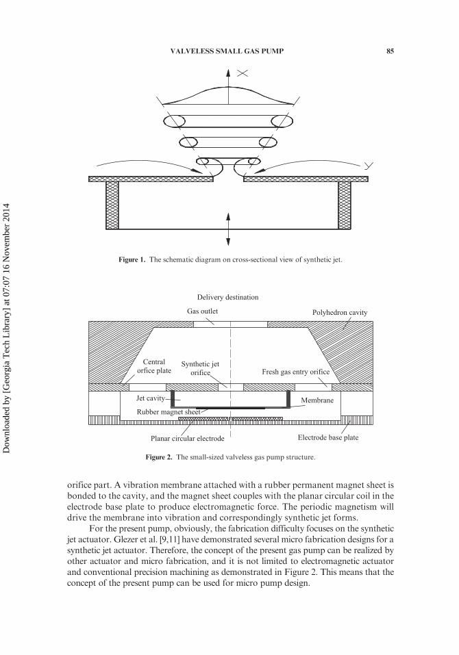
orifice part. A vibration membrane attached with a rubber permanent magnet sheet isbonded to the cavity, and the magnet sheet couples with the planar circular coil in theelectrode base plate to produce electromagnetic force. The periodic magnetism willdrive the membrane into vibration and correspondingly synthetic jet forms.
For the present pump, obviously, the fabrication difficulty focuses on the syntheticjet actuator. Glezer et al. [9,11] have demonstrated several micro fabrication designs for asynthetic jet actuator. Therefore, the concept of the present gas pump can be realized byother actuator and micro fabrication, and it is not limited to electromagnetic actuatorand conventional precision machining as demonstrated in Figure 2. This means that theconcept of the present pump can be used for micro pump design.
Figure 1. The schematic diagram on cross-sectional view of synthetic jet.
Polyhedron cavity
Central
orfice plate
Electrode base plate
Jet cavity Membrane
Rubber magnet sheet
Synthetic jet
orifice
Planar circular electrode
Fresh gas entry orifice
Gas outlet
Delivery destination
Figure 2. The small-sized valveless gas pump structure.
VALVELESS SMALL GAS PUMP 85
Dow
nloa
ded
by [
Geo
rgia
Tec
h L
ibra
ry]
at 0
7:07
16
Nov
embe
r 20
14
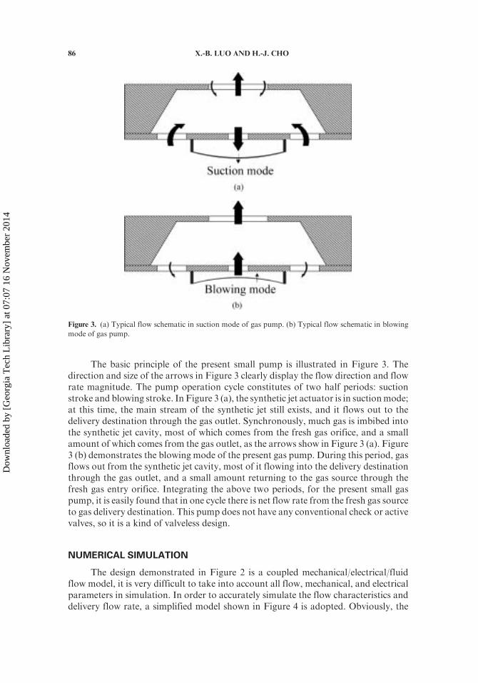
The basic principle of the present small pump is illustrated in Figure 3. Thedirection and size of the arrows in Figure 3 clearly display the flow direction and flowrate magnitude. The pump operation cycle constitutes of two half periods: suctionstroke and blowing stroke. In Figure 3 (a), the synthetic jet actuator is in suctionmode;at this time, the main stream of the synthetic jet still exists, and it flows out to thedelivery destination through the gas outlet. Synchronously, much gas is imbibed intothe synthetic jet cavity, most of which comes from the fresh gas orifice, and a smallamount of which comes from the gas outlet, as the arrows show in Figure 3 (a). Figure3 (b) demonstrates the blowing mode of the present gas pump. During this period, gasflows out from the synthetic jet cavity, most of it flowing into the delivery destinationthrough the gas outlet, and a small amount returning to the gas source through thefresh gas entry orifice. Integrating the above two periods, for the present small gaspump, it is easily found that in one cycle there is net flow rate from the fresh gas sourceto gas delivery destination. This pump does not have any conventional check or activevalves, so it is a kind of valveless design.
NUMERICAL SIMULATION
The design demonstrated in Figure 2 is a coupled mechanical/electrical/fluidflow model, it is very difficult to take into account all flow, mechanical, and electricalparameters in simulation. In order to accurately simulate the flow characteristics anddelivery flow rate, a simplified model shown in Figure 4 is adopted. Obviously, the
Figure 3. (a) Typical flow schematic in suction mode of gas pump. (b) Typical flow schematic in blowing
mode of gas pump.
86 X.-B. LUO AND H.-J. CHO
Dow
nloa
ded
by [
Geo
rgia
Tec
h L
ibra
ry]
at 0
7:07
16
Nov
embe
r 20
14
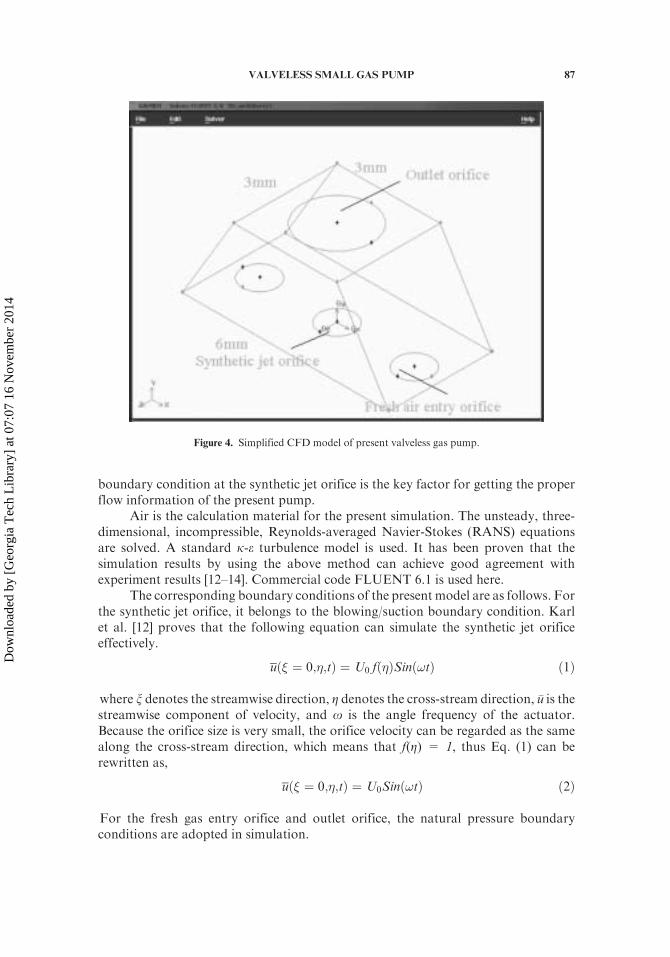
boundary condition at the synthetic jet orifice is the key factor for getting the properflow information of the present pump.
Air is the calculation material for the present simulation. The unsteady, three-dimensional, incompressible, Reynolds-averaged Navier-Stokes (RANS) equationsare solved. A standard k-e turbulence model is used. It has been proven that thesimulation results by using the above method can achieve good agreement withexperiment results [12–14]. Commercial code FLUENT 6.1 is used here.
The corresponding boundary conditions of the present model are as follows. Forthe synthetic jet orifice, it belongs to the blowing/suction boundary condition. Karlet al. [12] proves that the following equation can simulate the synthetic jet orificeeffectively.
uð� ¼ 0;�;tÞ ¼ U0 fð�ÞSinð!tÞ ð1Þ
where x denotes the streamwise direction, Z denotes the cross-stream direction, �u is thestreamwise component of velocity, and o is the angle frequency of the actuator.Because the orifice size is very small, the orifice velocity can be regarded as the samealong the cross-stream direction, which means that f(Z) = 1, thus Eq. (1) can berewritten as,
uð� ¼ 0;�;tÞ ¼ U0Sinð!tÞ ð2Þ
For the fresh gas entry orifice and outlet orifice, the natural pressure boundaryconditions are adopted in simulation.
Figure 4. Simplified CFD model of present valveless gas pump.
VALVELESS SMALL GAS PUMP 87
Dow
nloa
ded
by [
Geo
rgia
Tec
h L
ibra
ry]
at 0
7:07
16
Nov
embe
r 20
14
In the computations, the diameters of synthetic jet and fresh gas entry orifice are1 mm and the outlet orifice diameter is 2 mm. The height of the polyhedron cavity is2.5 mm; other main dimensions can be found from Figure 4. Based on the experimentsof a synthetic jet actuator [10,11,13,15,16], the orifice averaging maximum velocityU0
is assumed as 10 m/s and the actuator’s frequency is 1000 Hz.The convergence studies on grids, time steps in one cycle, and maximum
iteration times in one time step are conducted before the calculation. They arerefined until the flow field changes by 0.8%. Finally, 16,542 grids and 20 timesteps per cycle are used in the simulation. The residual control of the continuityequation is 0.01%.
ANALYSIS AND DISCUSSION
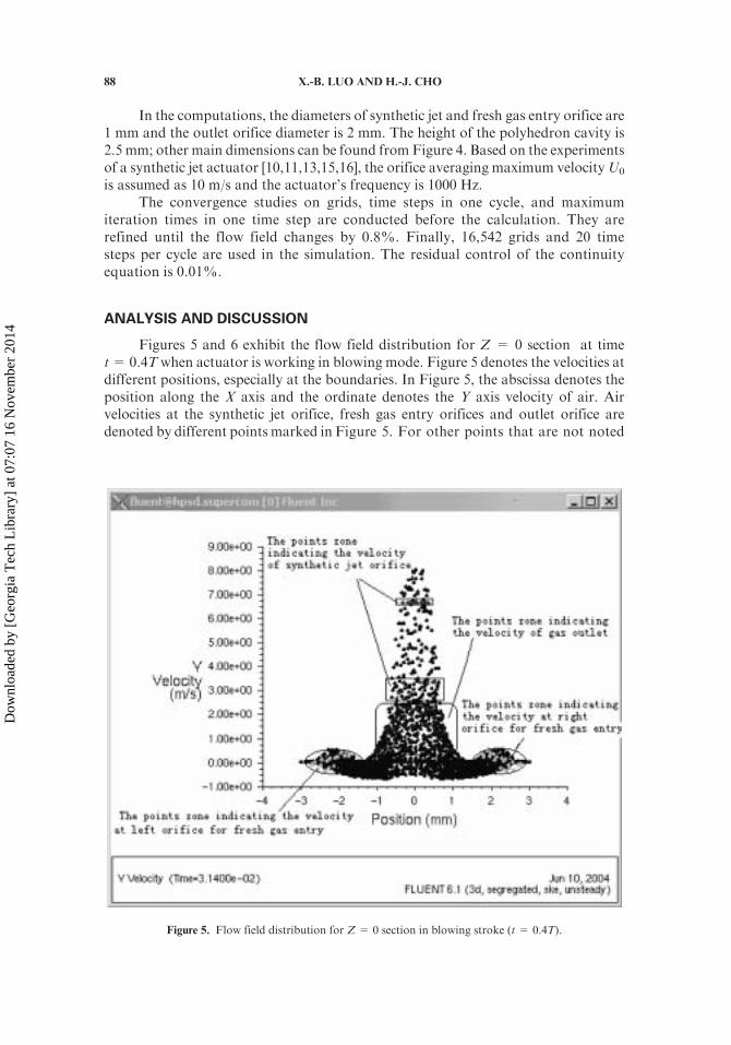
Figures 5 and 6 exhibit the flow field distribution for Z = 0 section at timet=0.4Twhen actuator is working in blowing mode. Figure 5 denotes the velocities atdifferent positions, especially at the boundaries. In Figure 5, the abscissa denotes theposition along the X axis and the ordinate denotes the Y axis velocity of air. Airvelocities at the synthetic jet orifice, fresh gas entry orifices and outlet orifice aredenoted by different points marked in Figure 5. For other points that are not noted
Figure 5. Flow field distribution for Z = 0 section in blowing stroke (t = 0.4T).
88 X.-B. LUO AND H.-J. CHO
Dow
nloa
ded
by [
Geo
rgia
Tec
h L
ibra
ry]
at 0
7:07
16
Nov
embe
r 20
14
in Figure 5, they denote the velocities inside the polyhedron cavity. It can beseen from Figure 5 that the velocities at the synthetic jet orifice are positive,which means that the synthetic jet actuator is working in blowing mode air flowsinto the polyhedron cavity from the synthetic jet cavity through the synthetic jetorifice. The fact that the velocities at gas outlet orifice are positive in Figure 5also demonstrates that air in the polyhedron cavity flows out from the outletorifice to the delivery destination. For air velocity at both fresh gas entryorifices, it is clear that a small amount of air in the polyhedron cavity flowsout from the fresh gas entry orifice since some points indicate negative velocity.According to the above discussion, it can be found that in the blowing stroke,most of the air coming from the synthetic jet cavity is delivered to its destinationfrom the outlet orifice, and a small amount of it returns to delivery source fromthe fresh gas entry orifice.
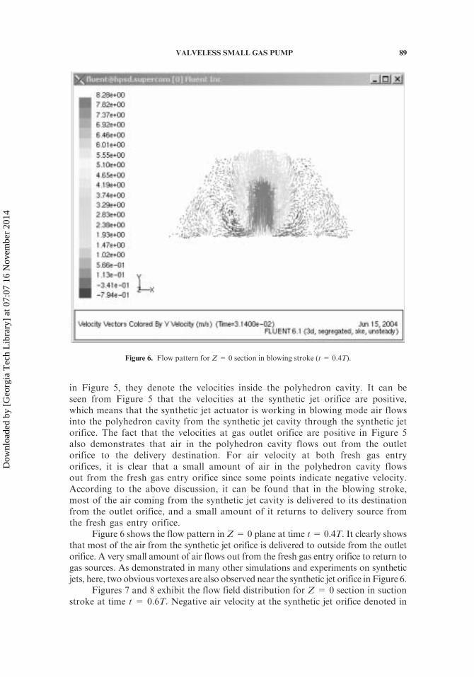
Figure 6 shows the flow pattern in Z= 0 plane at time t= 0.4T. It clearly showsthat most of the air from the synthetic jet orifice is delivered to outside from the outletorifice. A very small amount of air flows out from the fresh gas entry orifice to return togas sources. As demonstrated in many other simulations and experiments on syntheticjets, here, two obvious vortexes are also observed near the synthetic jet orifice in Figure 6.
Figures 7 and 8 exhibit the flow field distribution for Z = 0 section in suctionstroke at time t = 0.6T. Negative air velocity at the synthetic jet orifice denoted in
Figure 6. Flow pattern for Z = 0 section in blowing stroke (t = 0.4T).
VALVELESS SMALL GAS PUMP 89
Dow
nloa
ded
by [
Geo
rgia
Tec
h L
ibra
ry]
at 0
7:07
16
Nov
embe
r 20
14
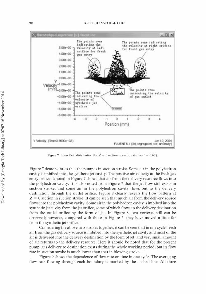
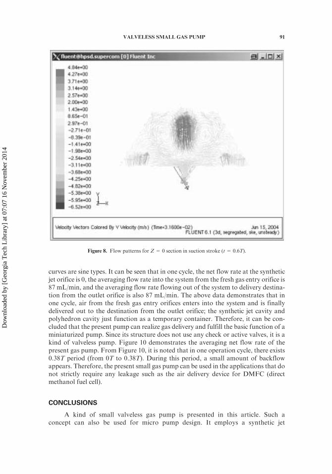
Figure 7 demonstrates that the pump is in suction stroke. Some air in the polyhedroncavity is imbibed into the synthetic jet cavity. The positive air velocity at the fresh gasentry orifice denoted in Figure 7 shows that air from the delivery resource flows intothe polyhedron cavity. It is also noted from Figure 7 that the jet flow still exists insuction stroke, and some air in the polyhedron cavity flows out to the deliverydestination through the outlet orifice. Figure 8 clearly reveals the flow pattern atZ= 0 section in suction stroke. It can be seen that much air from the delivery sourceflows into the polyhedron cavity. Some air in the polyhedron cavity is imbibed into thesynthetic jet cavity from the jet orifice, some of which flows to the delivery destinationfrom the outlet orifice by the form of jet. In Figure 8, two vortexes still can beobserved; however, compared with those in Figure 6, they have moved a little farfrom the synthetic jet orifice.
Considering the above two strokes together, it can be seen that in one cycle, freshair from the gas delivery source is imbibed into the synthetic jet cavity and most of theair is delivered into the delivery destination by the form of jet, and very small amountof air returns to the delivery resource. Here it should be noted that for the presentpump, gas delivery to destination exists during the whole working period, but its flowrate in suction stroke is much lower than that in blowing stroke.
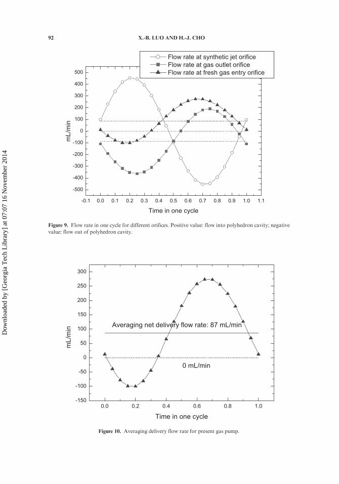
Figure 9 shows the dependence of flow rate on time in one cycle. The averagingflow rate flowing through each boundary is marked by the dashed line. All three
Figure 7. Flow field distribution for Z = 0 section in suction stroke (t = 0.6T).
90 X.-B. LUO AND H.-J. CHO
Dow
nloa
ded
by [
Geo
rgia
Tec
h L
ibra
ry]
at 0
7:07
16
Nov
embe
r 20
14
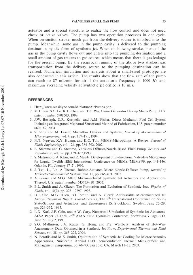
curves are sine types. It can be seen that in one cycle, the net flow rate at the syntheticjet orifice is 0, the averaging flow rate into the system from the fresh gas entry orifice is87 mL/min, and the averaging flow rate flowing out of the system to delivery destina-tion from the outlet orifice is also 87 mL/min. The above data demonstrates that inone cycle, air from the fresh gas entry orifices enters into the system and is finallydelivered out to the destination from the outlet orifice; the synthetic jet cavity andpolyhedron cavity just function as a temporary container. Therefore, it can be con-cluded that the present pump can realize gas delivery and fulfill the basic function of aminiaturized pump. Since its structure does not use any check or active valves, it is akind of valveless pump. Figure 10 demonstrates the averaging net flow rate of thepresent gas pump. From Figure 10, it is noted that in one operation cycle, there exists0.38T period (from 0T to 0.38T). During this period, a small amount of backflowappears. Therefore, the present small gas pump can be used in the applications that donot strictly require any leakage such as the air delivery device for DMFC (directmethanol fuel cell).
CONCLUSIONS
A kind of small valveless gas pump is presented in this article. Such aconcept can also be used for micro pump design. It employs a synthetic jet
Figure 8. Flow patterns for Z = 0 section in suction stroke (t = 0.6T).
VALVELESS SMALL GAS PUMP 91
Dow
nloa
ded
by [
Geo
rgia
Tec
h L
ibra
ry]
at 0
7:07
16
Nov
embe
r 20
14
-0.1 0.0 0.1 0.2 0.3 0.4 0.5 0.6 0.7 0.8 0.9 1.0 1.1
-500
-400
-300
-200
-100
0
100
200
300
400
500m
L/m
in
Time in one cycle
Flow rate at synthetic jet orifice
Flow rate at gas outlet orifice
Flow rate at fresh gas entry orifice
Figure 9. Flow rate in one cycle for different orifices. Positive value: flow into polyhedron cavity; negative
value: flow out of polyhedron cavity.
0.0 0.2 0.4 0.6 0.8 1.0-150
-100
-50
0
50
100
150
200
250
300
0 mL/min
Averaging net delivery flow rate: 87 mL/min
mL
/min
Time in one cycle
Figure 10. Averaging delivery flow rate for present gas pump.
92 X.-B. LUO AND H.-J. CHO
Dow
nloa
ded
by [
Geo
rgia
Tec
h L
ibra
ry]
at 0
7:07
16
Nov
embe
r 20
14
actuator and a special structure to realize the flow control and does not needcheck or active valves. The pump has two operation processes in one cycle.When on suction stroke, much gas from the delivery source is imbibed into thepump. Meanwhile, some gas in the pump cavity is delivered to the pumpingdestination by the form of synthetic jet. When on blowing stroke, most of thegas in the pump cavity flows out and enters into the pumping destination and asmall amount of gas returns to gas source, which means that there is gas leakagefor the present pump. By the reciprocal running of the above two strokes, gastransportation from the delivery source to the pumping destination can berealized. Numerical simulation and analysis about a small-sized prototype arealso conducted in this article. The results show that the flow rate of the pumpcan reach to 87 mL/min for air if the actuator’s frequency is 1000 Hz andmaximum averaging velocity at synthetic jet orifice is 10 m/s.
REFERENCES
1. Http://www.sensidyne.com/MiniatureAirPumps.php.
2. M.J. Tsai, S.C. Lo, R.T. Chen, and T.C. Wu, Ozone Generator Having Micro Pump, U.S.patent number 5908603, 1999.
3. J.W. Bostaph, C.R. Koripella, and A.M. Fisher, Direct Methanol Fuel Cell SystemIncluding an Integrated Methanol Sensor and Method of Fabrication, U.S. patent number6696189, 2004.
4. S. Shoji and M. Esashi, Microflow Devices and Systems, Journal of MicromechanicalMicroengineering, vol. 4, pp. 157–171, 1994.
5. N.T. Nguyen, X.Y. Huang, and K.C. Toh, MEMS-Micropumps: A Review, Journal ofFluids Engineering, vol. 124, pp. 384–392, 2002.
6. E. Stemme and G. Stemme, Valveless Diffuser/Nozzle-Based Fluid Pump, Sensors andActuators A, vol. 39, pp. 159–167,1993.
7. S.Matsumoto, A.Klein, andR.Maeda, Development of Bi-directional Valve-lessMicropump
for Liquid, Twelfth IEEE International Conference on MEMS, MEMS’99, pp. 141–146,Orlando, FL, January 17–21, 1999.
8. J. Tsai, L., Lin, A Thermal-Bubble-Actuated Micro Nozzle-Diffuser Pump, Journal of
Microelectromechanical Systems, vol. 11, pp. 665–671, 2002.9. A. Glezer and M.G. Allen, Micromachined Synthetic Jet Actuators and Applications
Thereof, U.S. patent number 6457654 B1, 2002.10. B.L. Smith and A. Glezer, The Formation and Evolution of Synthetic Jets, Physics of
Fluids, vol. 10(9), pp. 2281–2297, 1998.11. D.J. Coe, M.G. Allen, B.L. Smith, and A. Glezer, Addressable Micromachined Jet
Arrays, Technical Digest: Transducers 95, The 8th International Conference on Solid-
State-Sensors and Actuators, and Eurosensors IX Stockholm, Sweden, June 25–29,pp. 329–332, 1995.
12. L.D. Karl, J.F. Cain, and A.W. Cary, Numerical Simulation of Synthetic Jet Actuators,
AIAA Paper 97–1824, 28th AIAA Fluid Dynamics Conference, Snowmass Village, CO,June 29–July 2, 1997.
13. S.G. Mallinson, J.A. Reizes, G. Hong, and P.S. Westbury, Analysis of Hot-Wire
Anemometry Data Obtained in a Synthetic Jet Flow, Experimental Thermal and FluidScience, vol. 28, pp. 265–272, 2004.
14. N. Beratlis and M.K. Smith, Optimization of Synthetic Jet Cooling for MicroelectronicsApplications, Nineteenth Annual IEEE Semiconductor Thermal Measurement and
Management Symposium, pp. 66–73, San Jose, CA, March 11–13, 2003.
VALVELESS SMALL GAS PUMP 93
Dow
nloa
ded
by [
Geo
rgia
Tec
h L
ibra
ry]
at 0
7:07
16
Nov
embe
r 20
14
15. D.S. Kercher, J.B. Lee, O. Brand,M.G. Allen, and A. Glezer, Microjet Cooling Devices forThermal Management of Electronics, IEEE Transactions on Components and PackagingTechnologies, vol. 26(2), pp. 359–366, 1998.
16. C. Lee, G. Hong, Q.P. Ha, and S.G. Mallinson, A Piezoelectrically Actuated MicroSynthetic Jet for Active Flow Control, Sensor and Actuators A, vol. 108, pp. 168–174,2003.
94 X.-B. LUO AND H.-J. CHO
Dow
nloa
ded
by [
Geo
rgia
Tec
h L
ibra
ry]
at 0
7:07
16
Nov
embe
r 20
14