Embed Size (px)
Citation preview
ADDITIONAL INSTALLATION STEPS WHEN
DRAIN LINE REQUIRED
Toactivatethevalve, leakingwatermustrise7/8" to 1" in the drip pan (or other collectiondevice).Localplumbingcodesmayrequiretheinstallation of a drip pan with a drain lineand/or the ability to drain normal standingwater (usually condensate). Install the sup-plieddam (A) andcondensatedrain tube (B)
aroundthedrainlineopeningwhichwillallowwater to rise to at least 7/8", allowing anyexcess water to flow over the dam into thedrainlineandanynormalstandingcondensateto flow through the drain tube into the drainline.Peeloffthedraindam'sadhesivetapeback-ingandstickcondensatedraintube(B) tothebottomsotubeendsextendbeyondbothsidesof the dam. Attach bothpieces so that they form adam around the drip pan'sdrain line opening. Pressfirmlytothebottomandsidesof thepan toensureawatertightseal.ThiscompletestheWAGSvalveinstallationonelectric heaters. See additional steps for oilandgasheatersbelow.Installthewaterheaterpermanufacturer’sinstructions.ADDITIONAL INSTALLATION FOR THER-
MOCOUPLE TYPE GAS WATER HEATERS
(INSTALL GOKIT7200-1)
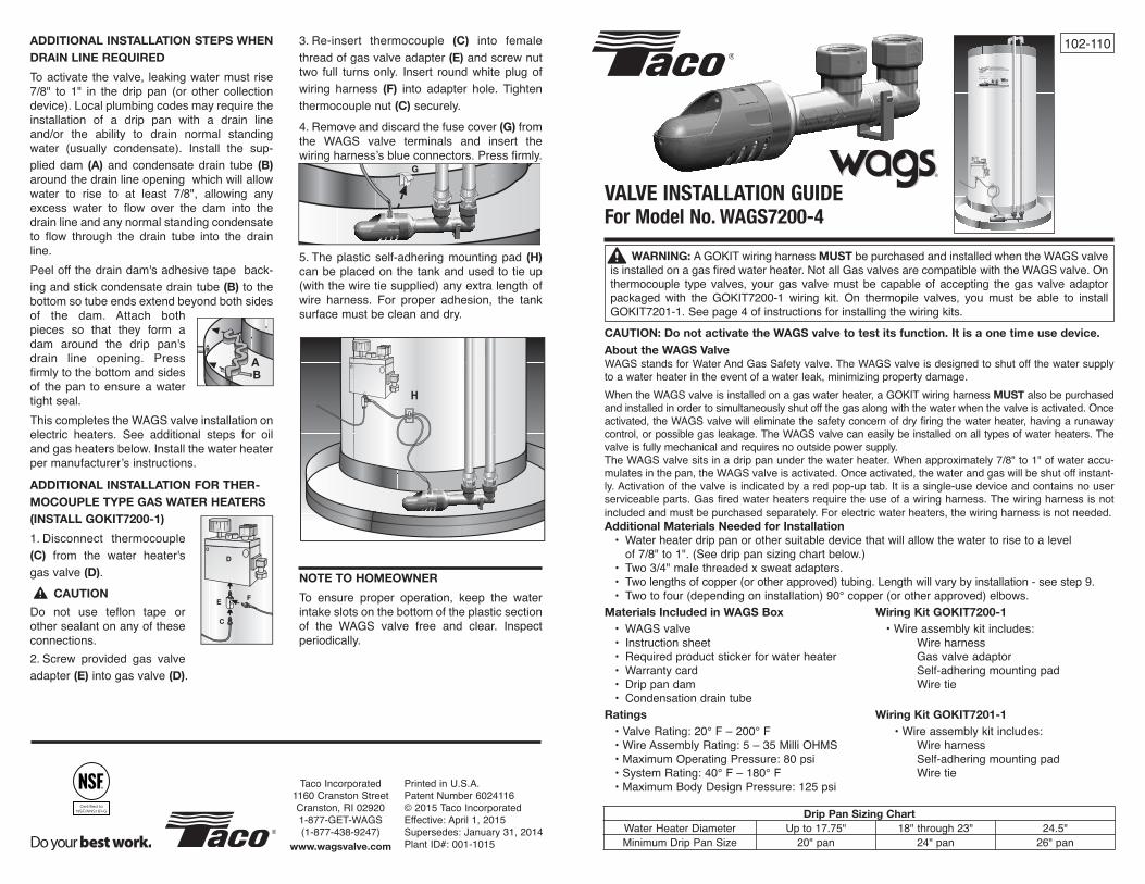
1. Disconnect thermocouple(C) from the water heater'sgasvalve(D).
CAUTION
Do not use teflon tape orothersealantonanyoftheseconnections.2. Screw provided gas valveadapter(E) intogasvalve(D).
3. Re-insert thermocouple (C) into femalethreadofgasvalveadapter(E) andscrewnuttwo full turnsonly. Insert roundwhiteplugofwiring harness (F) into adapter hole. Tightenthermocouplenut(C) securely.4. Removeanddiscardthefusecover(G) fromthe WAGS valve terminals and insert thewiringharness’sblueconnectors.Pressfirmly.
5. Theplasticself-adheringmountingpad (H)
canbeplacedonthetankandusedtotieup(withthewiretiesupplied)anyextralengthofwire harness. For proper adhesion, the tanksurfacemustbecleananddry.
NOTE TO HOMEOWNER
To ensure proper operation, keep the waterintakeslotsonthebottomoftheplasticsectionof the WAGS valve free and clear. Inspectperiodically.
G
H
AB
D
C
EF
PrintedinU.S.A.PatentNumber6024116©2015TacoIncorporatedEffective:April1,2015Supersedes:January31,2014PlantID#:001-1015
TacoIncorporated1160CranstonStreetCranston,RI029201-877-GET-WAGS(1-877-438-9247)
www.wagsvalve.com
About the WAGS ValveWAGSstandsforWaterAndGasSafetyvalve.TheWAGSvalveisdesignedtoshutoffthewatersupplytoawaterheaterintheeventofawaterleak,minimizingpropertydamage.WhentheWAGSvalveisinstalledonagaswaterheater,aGOKITwiringharnessMUST alsobepurchasedandinstalledinordertosimultaneouslyshutoffthegasalongwiththewaterwhenthevalveisactivated.Onceactivated,theWAGSvalvewilleliminatethesafetyconcernofdryfiringthewaterheater,havingarunawaycontrol,orpossiblegasleakage.TheWAGSvalvecaneasilybeinstalledonalltypesofwaterheaters.Thevalveisfullymechanicalandrequiresnooutsidepowersupply.TheWAGSvalvesitsinadrippanunderthewaterheater.Whenapproximately7/8"to1"ofwateraccu-mulatesinthepan,theWAGSvalveisactivated.Onceactivated,thewaterandgaswillbeshutoffinstant-ly.Activationofthevalveisindicatedbyaredpop-uptab.Itisasingle-usedeviceandcontainsnouserserviceableparts.Gasfiredwaterheatersrequiretheuseofawiringharness.Thewiringharnessisnotincludedandmustbepurchasedseparately.Forelectricwaterheaters,thewiringharnessisnotneeded.Additional Materials Needed for Installation
• Waterheaterdrippanorothersuitabledevicethatwillallowthewatertorisetoalevelof7/8"to1".(Seedrippansizingchartbelow.)
• Two3/4"malethreadedxsweatadapters.• Twolengthsofcopper(orotherapproved)tubing.Lengthwillvarybyinstallation-seestep9.• Twotofour(dependingoninstallation)90°copper(orotherapproved)elbows.Materials Included in WAGS Box Wiring Kit GOKIT7200-1
• WAGSvalve •Wireassemblykitincludes:• Instructionsheet Wireharness• Requiredproductstickerforwaterheater Gasvalveadaptor• Warrantycard Self-adheringmountingpad• Drippandam Wiretie• CondensationdraintubeRatings Wiring Kit GOKIT7201-1
•ValveRating:20°F–200°F •Wireassemblykitincludes:•WireAssemblyRating:5–35MilliOHMS Wireharness•MaximumOperatingPressure:80psi Self-adheringmountingpad•SystemRating:40°F–180°F Wiretie•MaximumBodyDesignPressure:125psi
102-110
Drip Pan Sizing Chart
WaterHeaterDiameter Upto17.75" 18"through23" 24.5"MinimumDripPanSize 20"pan 24"pan 26"pan
WARNING: AGOKITwiringharness MUST bepurchasedandinstalledwhentheWAGSvalveisinstalledonagasfiredwaterheater.NotallGasvalvesarecompatiblewiththeWAGSvalve.Onthermocouple type valves, your gas valvemust be capable of accepting thegas valveadaptorpackaged with the GOKIT7200-1 wiring kit. On thermopile valves, you must be able to installGOKIT7201-1.Seepage4ofinstructionsforinstallingthewiringkits.
CAUTION: Do not activate the WAGS valve to test its function. It is a one time use device.
VALVE INSTALLATION GUIDEFor Model No. WAGS7200-4
10.Solder3/4"malethreadedxsweatadaptersonto the tubing away from theWAGS valve.Allowtubingandadapterstocool.
CAUTION
Donotsolderorheatthe3/4"threadedportsontheWAGSvalve.Thiscoulddamagethevalve, resulting in impropervalveoperation,seriousinjuryorpropertydamage.11. Screw the two lengths of tubing into thevalveportsuntilsnug,keepingthevalveinteriorfreeofexcessivetapeorsealant.12.Placethevalvebacksothatitsitsflatonthedrippanbottom.Makesuretheendsofthecop-pertubing(orotherapprovedtubing)alignwiththesupplylineandthewaterheater's"COLDIN"portrespectively.13. Finish the piping by attaching the coldwatersupplylinetotheendofthetubinggoinginto the "IN" port of theWAGSvalveandbyattaching the end of the tubing coming fromthe"OUT"portoftheWAGSvalvetothewaterheater'scoldwaterinlet.
NOTE
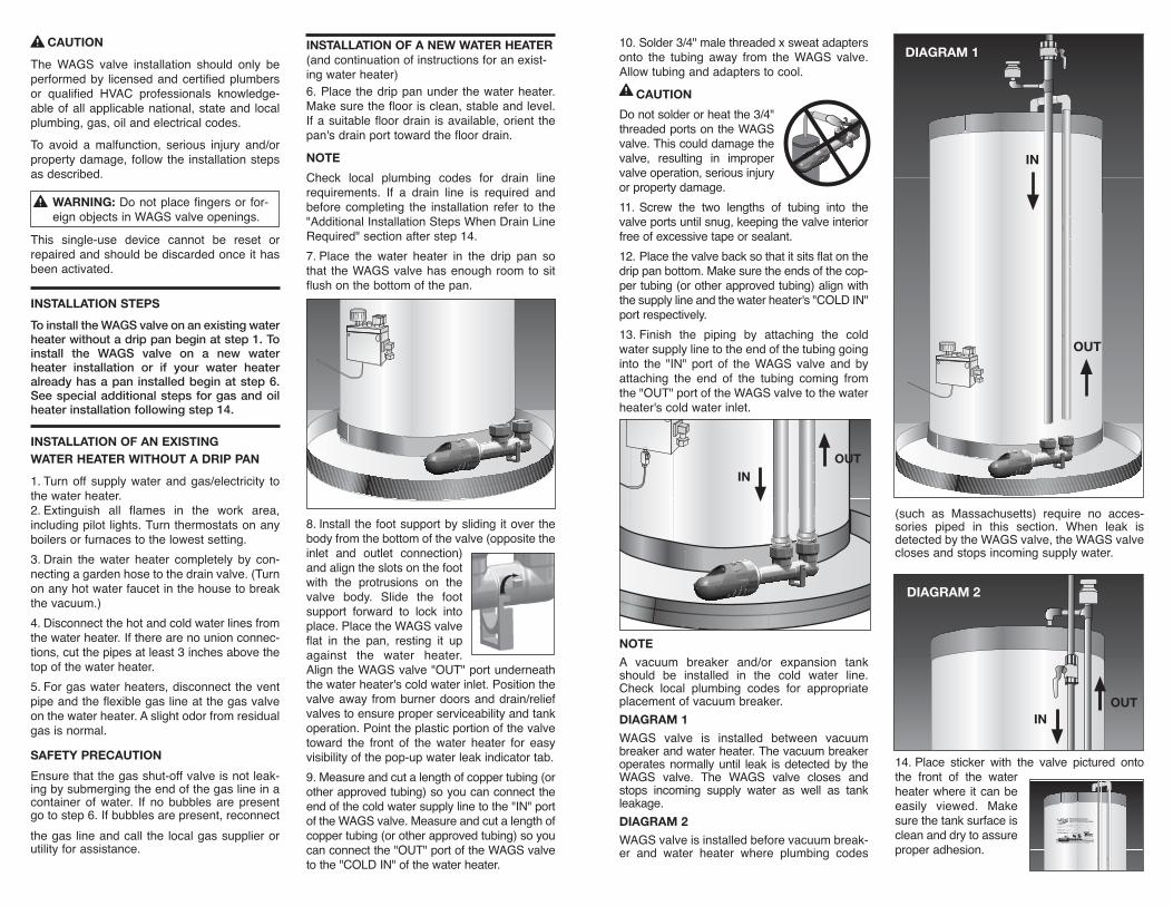
A vacuum breaker and/or expansion tankshould be installed in the cold water line.Check local plumbing codes for appropriateplacementofvacuumbreaker.DIAGRAM 1
WAGS valve is installed between vacuumbreakerandwaterheater.Thevacuumbreakeroperatesnormallyuntil leak isdetectedby theWAGS valve. The WAGS valve closes andstops incoming supply water as well as tankleakage.DIAGRAM 2
WAGSvalveisinstalledbeforevacuumbreak-er and water heater where plumbing codes
(such as Massachusetts) require no acces-sories piped in this section. When leak isdetectedbytheWAGSvalve,theWAGSvalveclosesandstopsincomingsupplywater.
14.Place sticker with the valve pictured ontothe front of the waterheaterwhere itcanbeeasily viewed. Makesurethetanksurfaceiscleananddrytoassureproperadhesion.
OUT
DIAGRAM 1
IN
INOUT
DIAGRAM 2
INOUT
CAUTION
TheWAGS valve installation should only beperformedby licensedandcertifiedplumbersor qualified HVAC professionals knowledge-ableofallapplicablenational,stateandlocalplumbing,gas,oilandelectricalcodes.To avoid amalfunction, serious injury and/orpropertydamage, followthe installationstepsasdescribed.
This single-use device cannot be reset orrepairedandshouldbediscardedonceithasbeenactivated.
INSTALLATION STEPS
To install the WAGS valve on an existing waterheater without a drip pan begin at step 1. Toinstall the WAGS valve on a new waterheater installation or if your water heateralready has a pan installed begin at step 6.See special additional steps for gas and oilheater installation following step 14.
INSTALLATION OF AN EXISTING
WATER HEATER WITHOUT A DRIP PAN
1. Turnoff supplywaterandgas/electricity tothewaterheater.2. Extinguish all flames in the work area,includingpilot lights.Turnthermostatsonanyboilersorfurnacestothelowestsetting.3. Drain thewater heater completely by con-nectingagardenhosetothedrainvalve.(Turnonanyhotwaterfaucetinthehousetobreakthevacuum.)4. Disconnectthehotandcoldwaterlinesfromthewaterheater.Iftherearenounionconnec-tions,cutthepipesatleast3inchesabovethetopofthewaterheater.5. Forgaswaterheaters,disconnecttheventpipeandtheflexiblegaslineatthegasvalveonthewaterheater.Aslightodorfromresidualgasisnormal.
SAFETY PRECAUTION
Ensurethatthegasshut-offvalveisnotleak-ingbysubmergingtheendofthegaslineinacontainer ofwater. If no bubbles are presentgotostep6.Ifbubblesarepresent,reconnectthegaslineandcall the localgassupplierorutilityforassistance.
INSTALLATION OF A NEW WATER HEATER
(andcontinuationofinstructionsforanexist-ingwaterheater)6.Placethedrippanunder thewaterheater.Makesurethefloorisclean,stableandlevel.Ifasuitablefloordrain isavailable,orientthepan'sdrainporttowardthefloordrain.NOTE
Check local plumbing codes for drain linerequirements. If a drain line is required andbeforecompleting the installation refer to the"AdditionalInstallationStepsWhenDrainLineRequired"sectionafterstep14.7. Place the water heater in the drip pan sothat theWAGSvalvehasenoughroomtositflushonthebottomofthepan.
8. Install thefootsupportbyslidingitoverthebodyfromthebottomofthevalve(oppositetheinlet and outlet connection)andaligntheslotsonthefootwith the protrusions on thevalve body. Slide the footsupport forward to lock intoplace.PlacetheWAGSvalveflat in the pan, resting it upagainst the water heater.AligntheWAGSvalve"OUT"portunderneaththewaterheater'scoldwaterinlet.Positionthevalveaway fromburnerdoorsanddrain/reliefvalvestoensureproperserviceabilityandtankoperation.Pointtheplasticportionofthevalvetoward the front of thewater heater for easyvisibilityofthepop-upwaterleakindicatortab.9. Measureandcutalengthofcoppertubing(orotherapprovedtubing)soyoucanconnecttheendofthecoldwatersupplylinetothe"IN"portoftheWAGSvalve.Measureandcutalengthofcoppertubing(orotherapprovedtubing)soyoucanconnectthe"OUT"portoftheWAGSvalvetothe"COLDIN"ofthewaterheater.
WARNING: Donotplacefingersorfor-eignobjectsinWAGSvalveopenings.