Embed Size (px)
Citation preview
The Professional environment at Henfel encourages collaboration, team work and development of leaderships able of taking decisions and creating solutions, which impacts the service quality. An example of it is the organizational identity of the company, developed and established by its collaborators during the strategic planning of 2010, and that contemplates the Values that guide the relationships in all the company’s hologram, its Mission, and Vision.
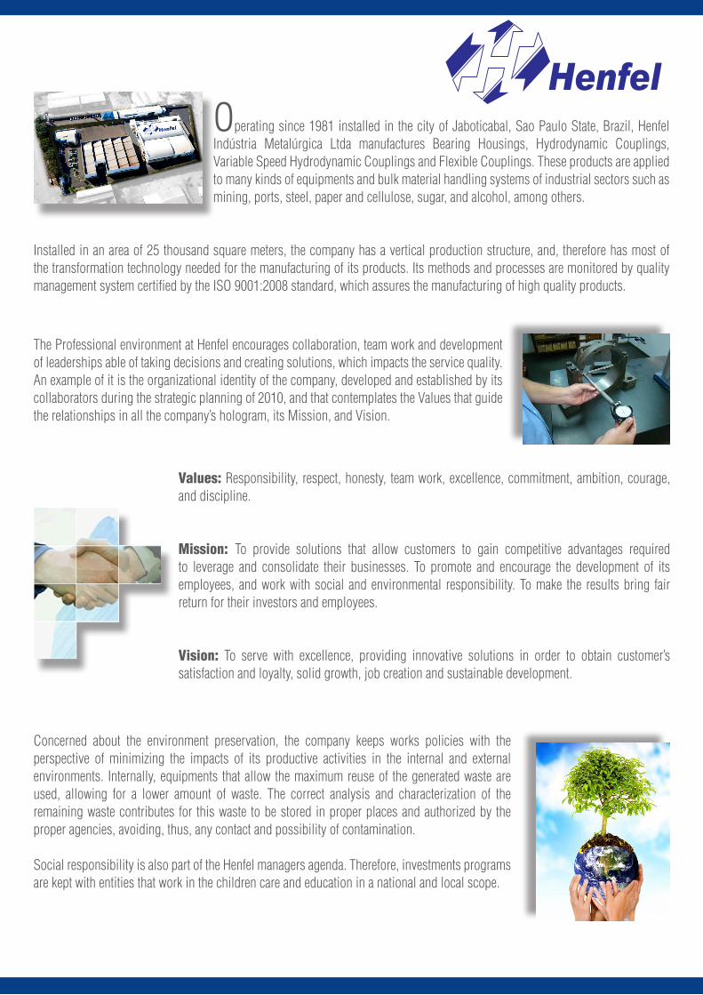
Operating since 1981 installed in the city of Jaboticabal, Sao Paulo State, Brazil, Henfel Indústria Metalúrgica Ltda manufactures Bearing Housings, Hydrodynamic Couplings, Variable Speed Hydrodynamic Couplings and Flexible Couplings. These products are applied to many kinds of equipments and bulk material handling systems of industrial sectors such as mining, ports, steel, paper and cellulose, sugar, and alcohol, among others.
Installed in an area of 25 thousand square meters, the company has a vertical production structure, and, therefore has most of the transformation technology needed for the manufacturing of its products. Its methods and processes are monitored by quality management system certified by the ISO 9001:2008 standard, which assures the manufacturing of high quality products.
Values: Responsibility, respect, honesty, team work, excellence, commitment, ambition, courage, and discipline.
Mission: To provide solutions that allow customers to gain competitive advantages required to leverage and consolidate their businesses. To promote and encourage the development of its employees, and work with social and environmental responsibility. To make the results bring fair return for their investors and employees.
Vision: To serve with excellence, providing innovative solutions in order to obtain customer’s satisfaction and loyalty, solid growth, job creation and sustainable development.
Concerned about the environment preservation, the company keeps works policies with the perspective of minimizing the impacts of its productive activities in the internal and external environments. Internally, equipments that allow the maximum reuse of the generated waste are used, allowing for a lower amount of waste. The correct analysis and characterization of the remaining waste contributes for this waste to be stored in proper places and authorized by the proper agencies, avoiding, thus, any contact and possibility of contamination.
Social responsibility is also part of the Henfel managers agenda. Therefore, investments programs are kept with entities that work in the children care and education in a national and local scope.
www.henfel.com.br
2 ÍNDEX
Henflex HDF Flexible Couplings 3
Dimensioning 3
Service Factors 4
Attention 4
Constructive Forms 5 the 6
Dimensional Tables 7 to 11
Dimensional HDF 7
Dimensional HDFS 8
Dimensional HDFF 9
Dimensional HDFC 10
Dimensional HDFD 11
Feather Key and Keyway Dimensions 12
Alignment 13
Admissible Misalignment 13
Flexible Coupling Henflex HXP 14
Coupling Size Selection 14
Service Factors 15
Application Conditions 15
Dimensional 16 to 18
Sizes 4 to 14 16
Sizes 16, 18 and 20 16
Sizes 22 to 79 17
Feather Key and Keyway Dimensions 18
Material, Physical Characteristics and Application 18
Alignment 19 the 20
Misalignment 19 the 20
Balancing 20
www.henfel.com.br
3
Dimensioning
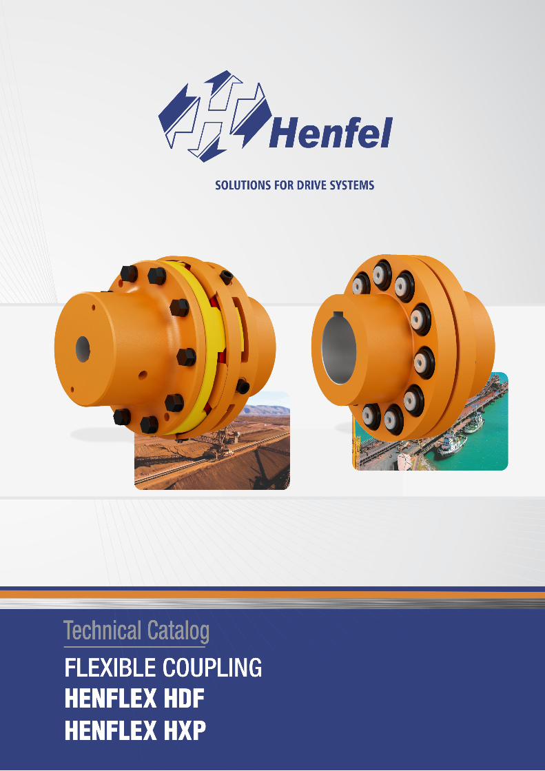
HENFLEX HDF FLEXIBLE COUPLINGS
Henf
lex
HDF
First of all, define the operational torque given by the equation bellow:
T0 = C x P nm
Where:T0 = System operational torque [Nm];P = Input power [kW or HP];nm= Rotation speed [rpm];C:C = 9550 for power in kW;C = 7030 for power in HP.
From the operational torque, the coupling’s nominal torque is obtained (Tna), which is given by:Tna ≥ T0 x f1
Where: Tna =Coupling nominal torque; f1 = Service factor (see table on page 4).
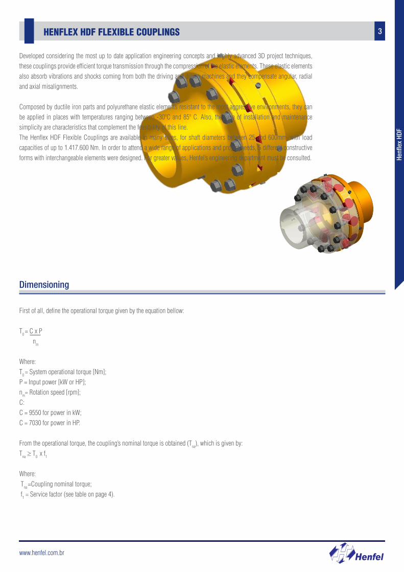
Developed considering the most up to date application engineering concepts and highly advanced 3D project techniques, these couplings provide efficient torque transmission through the compression of the elastic elements. These elastic elements also absorb vibrations and shocks coming from both the driving and driven machines and they compensate angular, radial and axial misalignments.
Composed by ductile iron parts and polyurethane elastic elements resistant to the most aggressive environments, they can be applied in places with temperatures ranging between -30ºC and 85º C. Also, the ease of installation and maintenance simplicity are characteristics that complement the feasibility of this line.The Henflex HDF Flexible Couplings are available in many sizes, for shaft diameters between 25 and 600mm, with load capacities of up to 1.417.600 Nm. In order to attend a wide range of applications and project needs, 5 different constructive forms with interchangeable elements were designed. For greater values, Henfel’s engineering department must be consulted.
www.henfel.com.br
4 SERVICE FACTORS
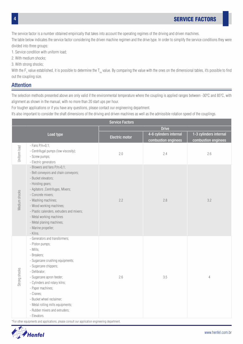
Service Factors
Load typeDrive
Electric motor4-6 cylinders internal
combustion enginees
1-3 cylinders internal
combustion enginees
Unifo
rm lo
ad - Fans P/n=0,1;- Centrifugal pumps (low viscosity);- Screw pumps;- Electric generators
2.0 2.4 2.6
Med
ium
shoc
ks
- Blowers and fans P/n>0,1;- Belt conveyors and chain conveyors;- Bucket elevators;- Hoisting gears;- Agitators ,Centrifuges, Mixers;- Concrete mixers;- Washing machines;- Wood working machines;- Plastic calenders, extruders and mixers;- Metal working machines- Metal planing machines;- Marine propeller;- Kilns.
2.2 2.8 3.2
Stro
ng sh
ocks
- Generators and transformers;- Piston pumps;- Mills;- Breakers;- Sugarcane crushing equipments;- Sugarcane chippers;- Defibrator;- Sugarcane apron feeder;- Cylinders and rotary kilns;- Paper machines;- Cranes;- Bucket wheel reclaimer;- Metal rolling mills equipments;- Rubber mixers and extruders;- Elevators.
2.6 3.5 4
*For other equipments and applications, please consult our application engineering department.
The selection methods presented above are only valid if the environmental temperature where the coupling is applied ranges between -30ºC and 85ºC, with alignment as shown in the manual, with no more than 20 start ups per hour.For tougher applications or if you have any questions, please contact our engineering department.It’s also important to consider the shaft dimensions of the driving and driven machines as well as the admissible rotation speed of the couplings.
Attention
The service factor is a number obtained empirically that takes into account the operating regimes of the driving and driven machines.The table below indicates the service factor considering the driven machine regimen and the drive type. In order to simplify the service conditions they were divided into three groups:1. Service condition with uniform load;2. With medium shocks;3. With strong shocks;With the F1 value established, it is possible to determine the Tna value. By comparing the value with the ones on the dimensional tables, it’s possible to find out the coupling size.
www.henfel.com.br
5CONSTRUCTIVE FORMS
Henf
lex
HDF
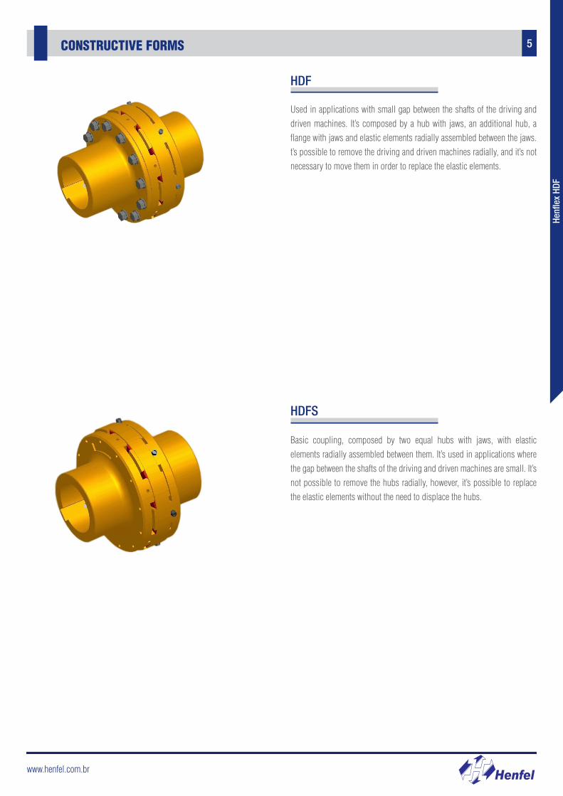
HDF
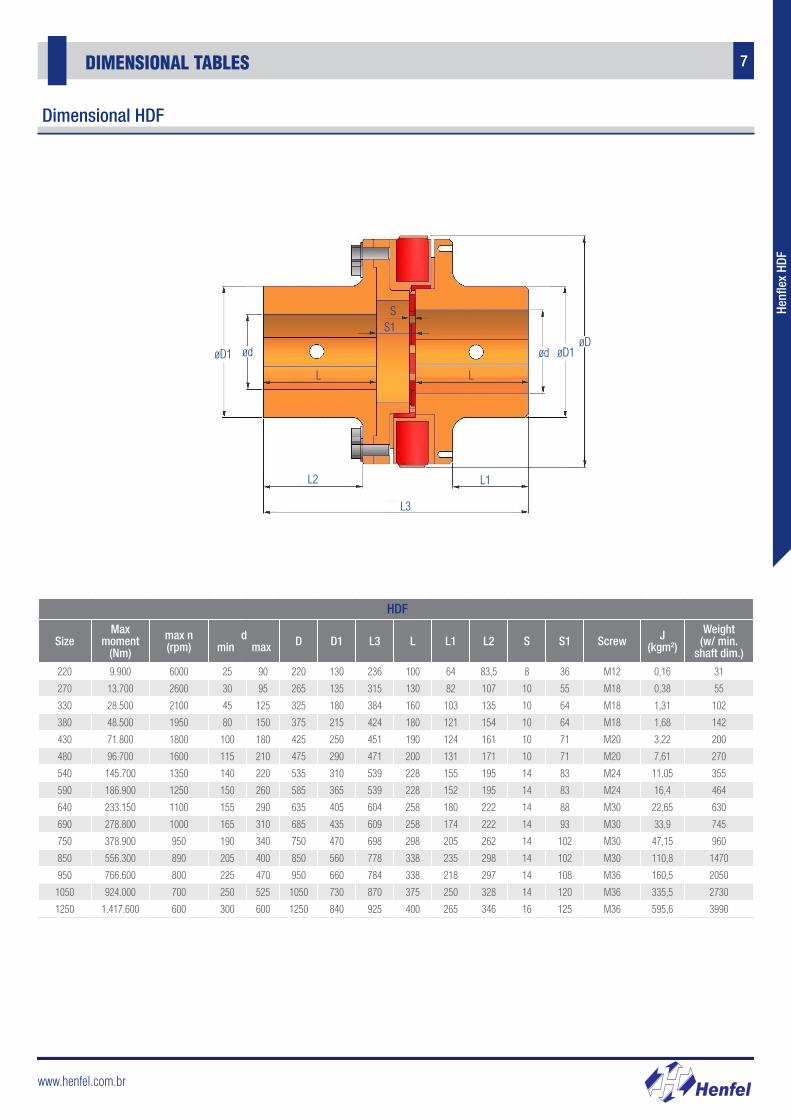
Used in applications with small gap between the shafts of the driving and driven machines. It’s composed by a hub with jaws, an additional hub, a flange with jaws and elastic elements radially assembled between the jaws. t’s possible to remove the driving and driven machines radially, and it’s not necessary to move them in order to replace the elastic elements.
HDFS
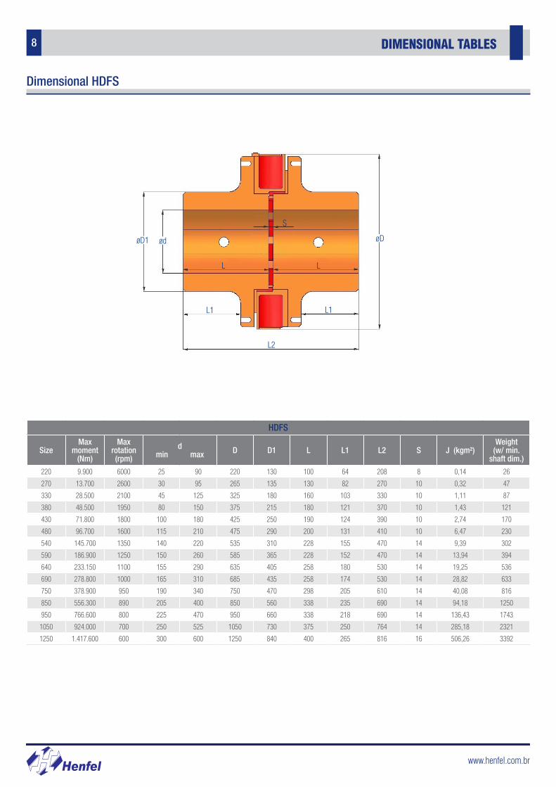
Basic coupling, composed by two equal hubs with jaws, with elastic elements radially assembled between them. It’s used in applications where the gap between the shafts of the driving and driven machines are small. It’s not possible to remove the hubs radially, however, it’s possible to replace the elastic elements without the need to displace the hubs.
www.henfel.com.br
6 CONSTRUCTIVE FORMS
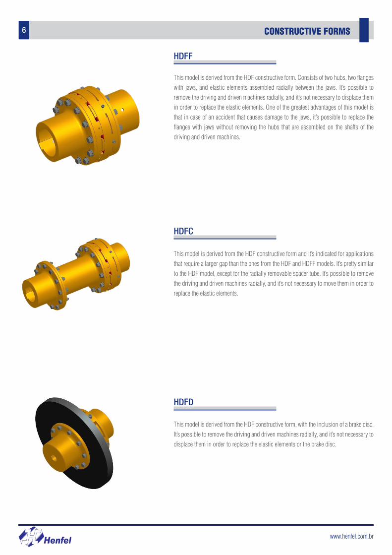
HDFF
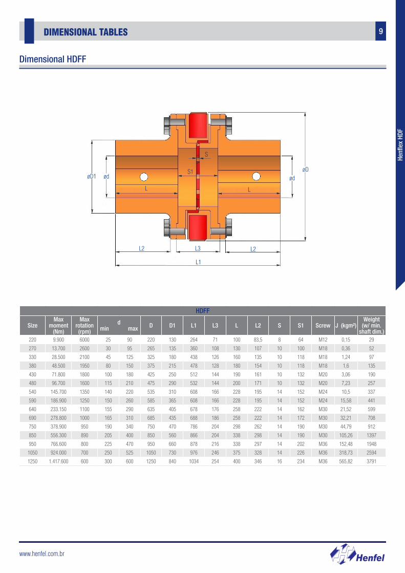
This model is derived from the HDF constructive form. Consists of two hubs, two flanges with jaws, and elastic elements assembled radially between the jaws. It’s possible to remove the driving and driven machines radially, and it’s not necessary to displace them in order to replace the elastic elements. One of the greatest advantages of this model is that in case of an accident that causes damage to the jaws, it’s possible to replace the flanges with jaws without removing the hubs that are assembled on the shafts of the driving and driven machines.
HDFC
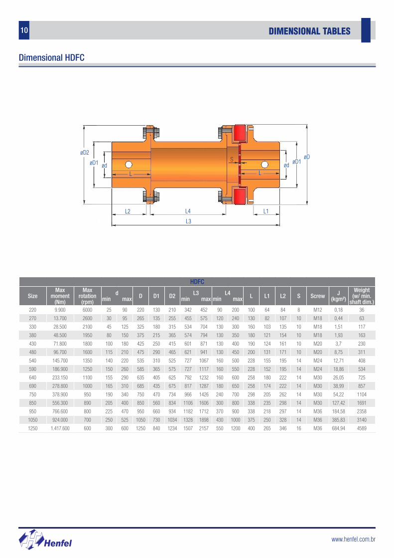
This model is derived from the HDF constructive form and it’s indicated for applications that require a larger gap than the ones from the HDF and HDFF models. It’s pretty similar to the HDF model, except for the radially removable spacer tube. It’s possible to remove the driving and driven machines radially, and it’s not necessary to move them in order to replace the elastic elements.
HDFD
This model is derived from the HDF constructive form, with the inclusion of a brake disc. It’s possible to remove the driving and driven machines radially, and it’s not necessary to displace them in order to replace the elastic elements or the brake disc.
www.henfel.com.br
7DIMENSIONAL TABLES
Henf
lex
HDF
Dimensional HDF
L3
L1L2
L L
SS1
ødøD1 ød øD1øD
HDF
SizeMax
moment (Nm)
max n (rpm)
dmin max D D1 L3 L L1 L2 S S1 Screw J
(kgm2)
Weight(w/ min.
shaft dim.)
220 9.900 6000 25 90 220 130 236 100 64 83,5 8 36 M12 0,16 31
270 13.700 2600 30 95 265 135 315 130 82 107 10 55 M18 0,38 55
330 28.500 2100 45 125 325 180 384 160 103 135 10 64 M18 1,31 102
380 48.500 1950 80 150 375 215 424 180 121 154 10 64 M18 1,68 142
430 71.800 1800 100 180 425 250 451 190 124 161 10 71 M20 3,22 200
480 96.700 1600 115 210 475 290 471 200 131 171 10 71 M20 7,61 270
540 145.700 1350 140 220 535 310 539 228 155 195 14 83 M24 11,05 355
590 186.900 1250 150 260 585 365 539 228 152 195 14 83 M24 16,4 464
640 233.150 1100 155 290 635 405 604 258 180 222 14 88 M30 22,65 630
690 278.800 1000 165 310 685 435 609 258 174 222 14 93 M30 33,9 745
750 378.900 950 190 340 750 470 698 298 205 262 14 102 M30 47,15 960
850 556.300 890 205 400 850 560 778 338 235 298 14 102 M30 110,8 1470
950 766.600 800 225 470 950 660 784 338 218 297 14 108 M36 160,5 2050
1050 924.000 700 250 525 1050 730 870 375 250 328 14 120 M36 335,5 2730
1250 1.417.600 600 300 600 1250 840 925 400 265 346 16 125 M36 595,6 3990
www.henfel.com.br
8 DIMENSIONAL TABLES
Dimensional HDFS
HDFS
SizeMax
moment (Nm)
Max rotation (rpm)
dmin max D D1 L L1 L2 S J (kgm²)
Weight(w/ min.
shaft dim.)
220 9.900 6000 25 90 220 130 100 64 208 8 0,14 26
270 13.700 2600 30 95 265 135 130 82 270 10 0,32 47
330 28.500 2100 45 125 325 180 160 103 330 10 1,11 87
380 48.500 1950 80 150 375 215 180 121 370 10 1,43 121
430 71.800 1800 100 180 425 250 190 124 390 10 2,74 170
480 96.700 1600 115 210 475 290 200 131 410 10 6,47 230
540 145.700 1350 140 220 535 310 228 155 470 14 9,39 302
590 186.900 1250 150 260 585 365 228 152 470 14 13,94 394
640 233.150 1100 155 290 635 405 258 180 530 14 19,25 536
690 278.800 1000 165 310 685 435 258 174 530 14 28,82 633
750 378.900 950 190 340 750 470 298 205 610 14 40,08 816
850 556.300 890 205 400 850 560 338 235 690 14 94,18 1250
950 766.600 800 225 470 950 660 338 218 690 14 136,43 1743
1050 924.000 700 250 525 1050 730 375 250 764 14 285,18 2321
1250 1.417.600 600 300 600 1250 840 400 265 816 16 506,26 3392
L L
S
øD
L1 L1
ødøD1
L2
www.henfel.com.br
9DIMENSIONAL TABLES
Henf
lex
HDF
HDFF
SizeMax
moment (Nm)
Max rotation (rpm)
dmin max D D1 L1 L3 L L2 S S1 Screw J (kgm²)
Weight(w/ min.
shaft dim.)220 9.900 6000 25 90 220 130 264 71 100 83,5 8 64 M12 0,15 29
270 13.700 2600 30 95 265 135 360 108 130 107 10 100 M18 0,36 52
330 28.500 2100 45 125 325 180 438 126 160 135 10 118 M18 1,24 97
380 48.500 1950 80 150 375 215 478 128 180 154 10 118 M18 1,6 135
430 71.800 1800 100 180 425 250 512 144 190 161 10 132 M20 3,06 190
480 96.700 1600 115 210 475 290 532 144 200 171 10 132 M20 7,23 257
540 145.700 1350 140 220 535 310 608 166 228 195 14 152 M24 10,5 337
590 186.900 1250 150 260 585 365 608 166 228 195 14 152 M24 15,58 441
640 233.150 1100 155 290 635 405 678 176 258 222 14 162 M30 21,52 599
690 278.800 1000 165 310 685 435 688 186 258 222 14 172 M30 32,21 708
750 378.900 950 190 340 750 470 786 204 298 262 14 190 M30 44,79 912
850 556.300 890 205 400 850 560 866 204 338 298 14 190 M30 105,26 1397
950 766.600 800 225 470 950 660 878 216 338 297 14 202 M36 152,48 1948
1050 924.000 700 250 525 1050 730 976 246 375 328 14 226 M36 318,73 2594
1250 1.417.600 600 300 600 1250 840 1034 254 400 346 16 234 M36 565,82 3791
L2L2 L3
L L
S1
S
øDødøD1 ød
L1
Dimensional HDFF
www.henfel.com.br
10 DIMENSIONAL TABLES
HDFC
SizeMax
moment (Nm)
Max rotation (rpm)
dmin max D D1 D2 L3
min maxL4
min max L L1 L2 S Screw J (kgm²)
Weight(w/ min.
shaft dim.)220 9.900 6000 25 90 220 130 210 342 452 90 200 100 64 84 8 M12 0,18 36
270 13.700 2600 30 95 265 135 255 455 575 120 240 130 82 107 10 M18 0,44 63
330 28.500 2100 45 125 325 180 315 534 704 130 300 160 103 135 10 M18 1,51 117
380 48.500 1950 80 150 375 215 365 574 794 130 350 180 121 154 10 M18 1,93 163
430 71.800 1800 100 180 425 250 415 601 871 130 400 190 124 161 10 M20 3,7 230
480 96.700 1600 115 210 475 290 465 621 941 130 450 200 131 171 10 M20 8,75 311
540 145.700 1350 140 220 535 310 525 727 1067 160 500 228 155 195 14 M24 12,71 408
590 186.900 1250 150 260 585 365 575 727 1117 160 550 228 152 195 14 M24 18,86 534
640 233.150 1100 155 290 635 405 625 792 1232 160 600 258 180 222 14 M30 26,05 725
690 278.800 1000 165 310 685 435 675 817 1287 180 650 258 174 222 14 M30 38,99 857
750 378.900 950 190 340 750 470 734 966 1426 240 700 298 205 262 14 M30 54,22 1104
850 556.300 890 205 400 850 560 834 1106 1606 300 800 338 235 298 14 M30 127,42 1691
950 766.600 800 225 470 950 660 934 1182 1712 370 900 338 218 297 14 M36 184,58 2358
1050 924.000 700 250 525 1050 730 1034 1328 1898 430 1000 375 250 328 14 M36 385,83 3140
1250 1.417.600 600 300 600 1250 840 1234 1507 2157 550 1200 400 265 346 16 M36 684,94 4589
øD2
øD1 ød ød øD1øD
L3
L2 L1L4
LL
S
Dimensional HDFC
www.henfel.com.br
11DIMENSIONAL TABLES
Henf
lex
HDF
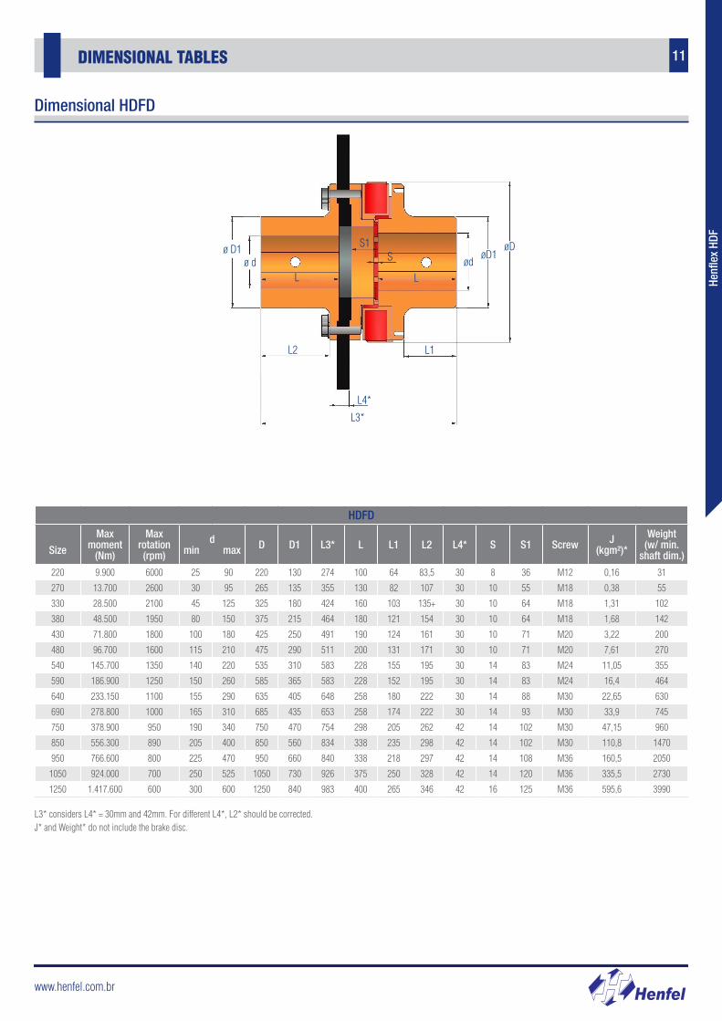
HDFD
Size
Max moment
(Nm)
Max rotation (rpm)
dmin max D D1 L3* L L1 L2 L4* S S1 Screw J
(kgm²)*
Weight(w/ min.
shaft dim.)
220 9.900 6000 25 90 220 130 274 100 64 83,5 30 8 36 M12 0,16 31
270 13.700 2600 30 95 265 135 355 130 82 107 30 10 55 M18 0,38 55
330 28.500 2100 45 125 325 180 424 160 103 135+ 30 10 64 M18 1,31 102
380 48.500 1950 80 150 375 215 464 180 121 154 30 10 64 M18 1,68 142
430 71.800 1800 100 180 425 250 491 190 124 161 30 10 71 M20 3,22 200
480 96.700 1600 115 210 475 290 511 200 131 171 30 10 71 M20 7,61 270
540 145.700 1350 140 220 535 310 583 228 155 195 30 14 83 M24 11,05 355
590 186.900 1250 150 260 585 365 583 228 152 195 30 14 83 M24 16,4 464
640 233.150 1100 155 290 635 405 648 258 180 222 30 14 88 M30 22,65 630
690 278.800 1000 165 310 685 435 653 258 174 222 30 14 93 M30 33,9 745
750 378.900 950 190 340 750 470 754 298 205 262 42 14 102 M30 47,15 960
850 556.300 890 205 400 850 560 834 338 235 298 42 14 102 M30 110,8 1470
950 766.600 800 225 470 950 660 840 338 218 297 42 14 108 M36 160,5 2050
1050 924.000 700 250 525 1050 730 926 375 250 328 42 14 120 M36 335,5 2730
1250 1.417.600 600 300 600 1250 840 983 400 265 346 42 16 125 M36 595,6 3990
ø D1ø d
L2 L1
L3*
L4*
ødøD1
øD
L L
SS1
L3* considers L4* = 30mm and 42mm. For different L4*, L2* should be corrected.J* and Weight* do not include the brake disc.
Dimensional HDFD
www.henfel.com.br
12 FEATHER KEY AND KEYWAY DIMENSIONS
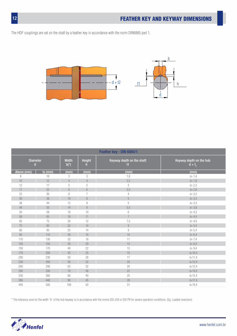
The HDF couplings are set on the shaft by a feather key in accordance with the norm DIN6885 part 1.
Feather key - DIN 6885/1
Diameterd
Widthb(*)
Heighth
Keyway depth on the shaftt1
Keyway depth on the hubd + t2
Above (mm) to (mm) (mm) (mm) (mm) (mm)8 10 3 3 1,8 d+ 1,410 12 4 4 2,5 d+ 1,812 17 5 5 3 d+ 2,317 22 6 6 3,5 d+ 2,822 30 8 7 4 d+ 3,330 38 10 8 5 d+ 3,338 44 12 8 5 d+ 3,344 50 14 9 5,5 d+ 3,850 58 16 10 6 d+ 4,358 65 18 11 7 d+ 4,465 75 20 12 7,5 d+ 4,975 85 22 14 9 d+ 5,485 95 25 14 9 d+ 5,495 110 28 16 10 d+ 6,4
110 130 32 18 11 d+ 7,4130 150 36 20 12 d+ 8,4150 170 40 22 13 d+ 9,4170 200 45 25 15 d+10,4200 230 50 28 17 d+11,4230 260 56 32 20 d+12,4260 290 63 32 20 d+12,4290 330 70 36 22 d+14,4330 380 80 40 25 d+15,4380 440 90 45 28 d+17,4440 500 100 50 31 d+19,4
* The tolerance zone for the width “b” of the hub keyway is in accordance with the norms ISO JS9 or ISO P9 for severe operation conditions. (Eg. Loaded reversion).
d + t2
d
ht1
b
www.henfel.com.br
13ALIGNMENT
Henf
lex
HDF
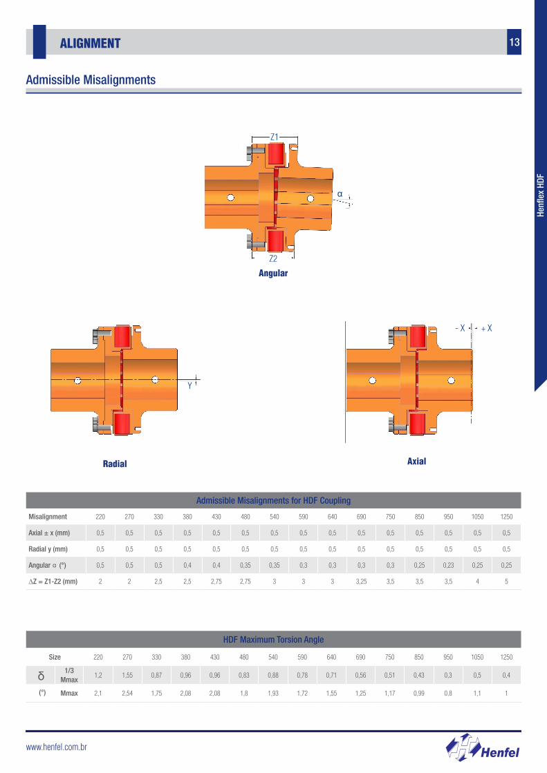
Admissible Misalignments for HDF Coupling
Misalignment 220 270 330 380 430 480 540 590 640 690 750 850 950 1050 1250
Axial ± x (mm) 0,5 0,5 0,5 0,5 0,5 0,5 0,5 0,5 0,5 0,5 0,5 0,5 0,5 0,5 0,5
Radial y (mm) 0,5 0,5 0,5 0,5 0,5 0,5 0,5 0,5 0,5 0,5 0,5 0,5 0,5 0,5 0,5
Angular (°) 0,5 0,5 0,5 0,4 0,4 0,35 0,35 0,3 0,3 0,3 0,3 0,25 0,23 0,25 0,25
∆Z = Z1-Z2 (mm) 2 2 2,5 2,5 2,75 2,75 3 3 3 3,25 3,5 3,5 3,5 4 5
α
HDF Maximum Torsion Angle
Size 220 270 330 380 430 480 540 590 640 690 750 850 950 1050 1250
1/3 Mmax
1,2 1,55 0,87 0,96 0,96 0,83 0,88 0,78 0,71 0,56 0,51 0,43 0,3 0,5 0,4
Mmax 2,1 2,54 1,75 2,08 2,08 1,8 1,93 1,72 1,55 1,25 1,17 0,99 0,8 1,1 1
δ
Radial Axial
Angular
Z1
Z2
α
- X + X
Y
(°)
Admissible Misalignments
www.henfel.com.br
14
Coupling Size Selection
FLEXIBLE COUPLING HENFLEX HXP
First of all, define the operational torque given by the equation bellowT0 = C x P , Where: nm
T0 = System operational torque [Nm];P = Input power [kW or HP];nm = Rotation speed [rpm];C:C = 9550 for power in kW;C = 7030 for power in HP.From the operational torque, the coupling’s nominal torque is obtained (Tna), which is given by:Tna ≥ T0 x f1
Where:Tna = Coupling nominal torque;f1 = Service factor (see table on page 16).
Obs: These couplings were dimensioned to withstand start up and braking at a maximum torque of up to three times the nominal torque of the coupling. These operations can be repeated 25 times per hour. However, should the coupling be submitted to loads involving shocks, the following equation must be considered:T = 3 x Tna ≥ Ts
Where:T = Maximum coupling torque;Ts = Maximum impact torque of the system.
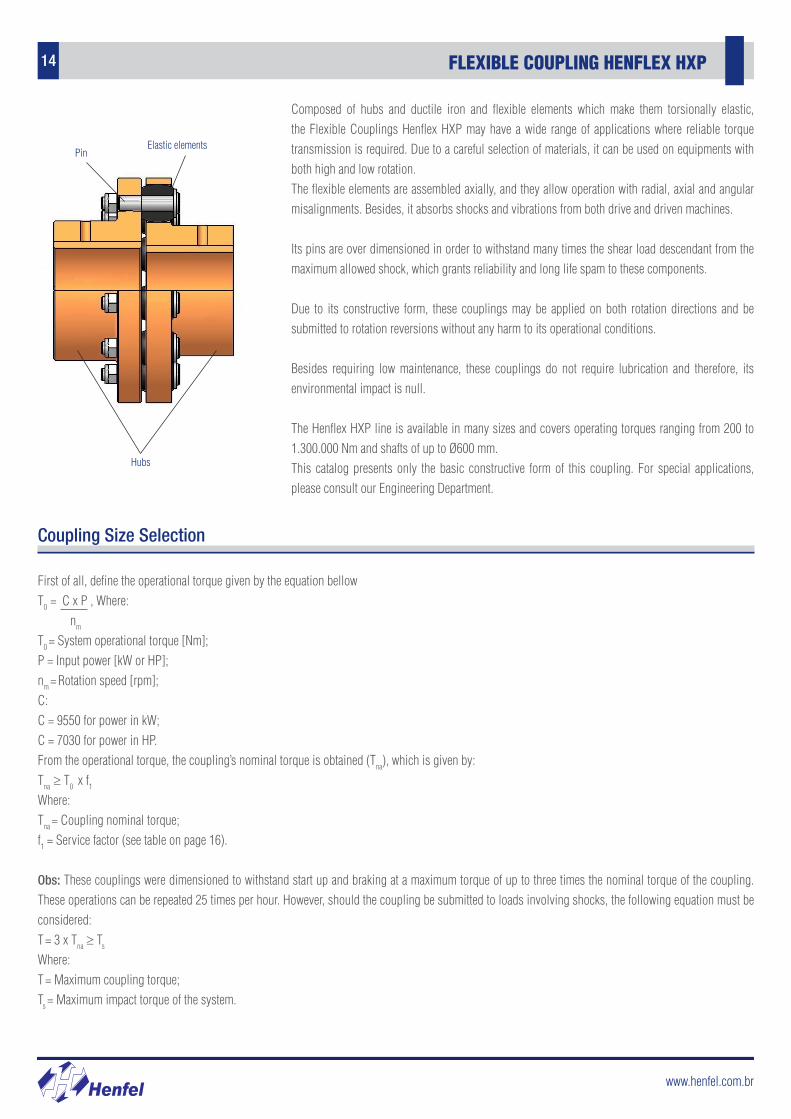
Composed of hubs and ductile iron and flexible elements which make them torsionally elastic, the Flexible Couplings Henflex HXP may have a wide range of applications where reliable torque transmission is required. Due to a careful selection of materials, it can be used on equipments with both high and low rotation.The flexible elements are assembled axially, and they allow operation with radial, axial and angular misalignments. Besides, it absorbs shocks and vibrations from both drive and driven machines.
Its pins are over dimensioned in order to withstand many times the shear load descendant from the maximum allowed shock, which grants reliability and long life spam to these components.
Due to its constructive form, these couplings may be applied on both rotation directions and be submitted to rotation reversions without any harm to its operational conditions.
Besides requiring low maintenance, these couplings do not require lubrication and therefore, its environmental impact is null.
The Henflex HXP line is available in many sizes and covers operating torques ranging from 200 to 1.300.000 Nm and shafts of up to Ø600 mm. This catalog presents only the basic constructive form of this coupling. For special applications, please consult our Engineering Department.
Hubs
PinElastic elements
www.henfel.com.br
15SERVICE FACTOR
Henf
lex
HDF
Henf
lex
HXP
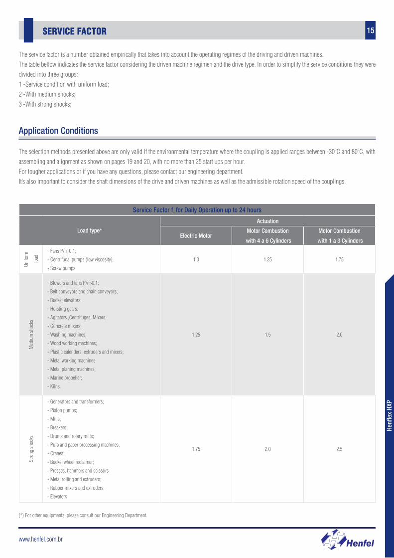
The service factor is a number obtained empirically that takes into account the operating regimes of the driving and driven machines.The table bellow indicates the service factor considering the driven machine regimen and the drive type. In order to simplify the service conditions they were divided into three groups:1 -Service condition with uniform load;2 -With medium shocks;3 -With strong shocks;
The selection methods presented above are only valid if the environmental temperature where the coupling is applied ranges between -30ºC and 80ºC, with assembling and alignment as shown on pages 19 and 20, with no more than 25 start ups per hour.For tougher applications or if you have any questions, please contact our engineering department.It’s also important to consider the shaft dimensions of the drive and driven machines as well as the admissible rotation speed of the couplings.
Service Factor f1 for Daily Operation up to 24 hours
Load type*
Actuation
Electric MotorMotor Combustion
with 4 a 6 Cylinders
Motor Combustion
with 1 a 3 Cylinders
Unifo
rm
load
- Fans P/n=0,1;
- Centrifugal pumps (low viscosity);
- Screw pumps
1.0 1.25 1.75
Med
ium
shoc
ks
- Blowers and fans P/n>0,1;
- Belt conveyors and chain conveyors;
- Bucket elevators;
- Hoisting gears;
- Agitators ,Centrifuges, Mixers;
- Concrete mixers;
- Washing machines;
- Wood working machines;
- Plastic calenders, extruders and mixers;
- Metal working machines
- Metal planing machines;
- Marine propeller;
- Kilns.
1.25 1.5 2.0
Stro
ng sh
ocks
- Generators and transformers;
- Piston pumps;
- Mills;
- Breakers;
- Drums and rotary mills;
- Pulp and paper processing machines;
- Cranes;
- Bucket wheel reclaimer;
- Presses, hammers and scissors
- Metal rolling and extruders;
- Rubber mixers and extruders;
- Elevators
1.75 2.0 2.5
Application Conditions
(*) For other equipments, please consult our Engineering Department.
www.henfel.com.br
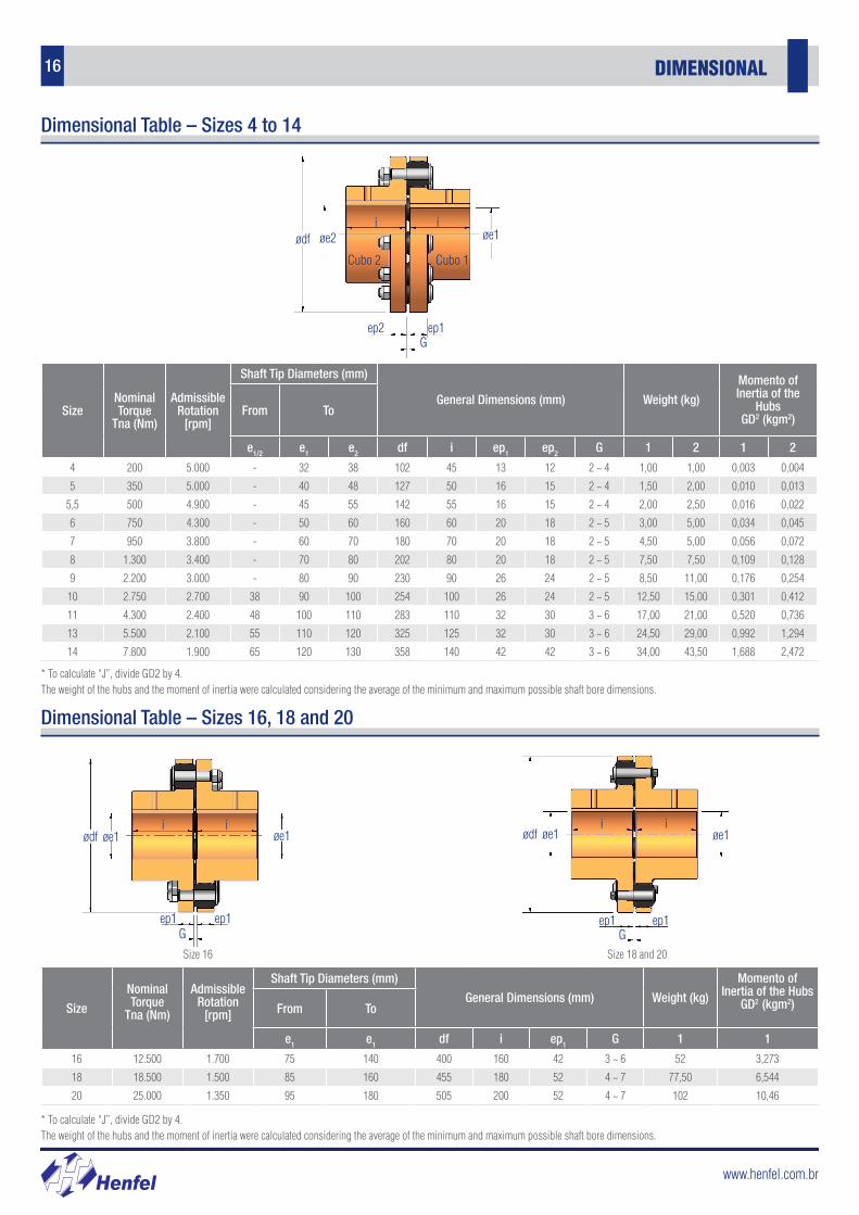
16 DIMENSIONAL
SizeNominal Torque
Tna (Nm)
Admissible Rotation
[rpm]
Shaft Tip Diameters (mm)
General Dimensions (mm) Weight (kg)
Momento of Inertia of the
HubsGD2 (kgm2)
From To
e1/2 e1 e2 df i ep1 ep2 G 1 2 1 2
4 200 5.000 - 32 38 102 45 13 12 2 ~ 4 1,00 1,00 0,003 0,004
5 350 5.000 - 40 48 127 50 16 15 2 ~ 4 1,50 2,00 0,010 0,013
5,5 500 4.900 - 45 55 142 55 16 15 2 ~ 4 2,00 2,50 0,016 0,022
6 750 4.300 - 50 60 160 60 20 18 2 ~ 5 3,00 5,00 0,034 0,045
7 950 3.800 - 60 70 180 70 20 18 2 ~ 5 4,50 5,00 0,056 0,072
8 1.300 3.400 - 70 80 202 80 20 18 2 ~ 5 7,50 7,50 0,109 0,128
9 2.200 3.000 - 80 90 230 90 26 24 2 ~ 5 8,50 11,00 0,176 0,254
10 2.750 2.700 38 90 100 254 100 26 24 2 ~ 5 12,50 15,00 0,301 0,412
11 4.300 2.400 48 100 110 283 110 32 30 3 ~ 6 17,00 21,00 0,520 0,736
13 5.500 2.100 55 110 120 325 125 32 30 3 ~ 6 24,50 29,00 0,992 1,294
14 7.800 1.900 65 120 130 358 140 42 42 3 ~ 6 34,00 43,50 1,688 2,472
* To calculate “J”, divide GD2 by 4.The weight of the hubs and the moment of inertia were calculated considering the average of the minimum and maximum possible shaft bore dimensions.
Size
Nominal Torque
Tna (Nm)
Admissible Rotation
[rpm]
Shaft Tip Diameters (mm)
General Dimensions (mm) Weight (kg)
Momento of Inertia of the Hubs
GD2 (kgm2)From To
e1 e1 df i ep1 G 1 1
16 12.500 1.700 75 140 400 160 42 3 ~ 6 52 3,273
18 18.500 1.500 85 160 455 180 52 4 ~ 7 77,50 6,544
20 25.000 1.350 95 180 505 200 52 4 ~ 7 102 10,46
Dimensional Table – Sizes 4 to 14
Dimensional Table – Sizes 16, 18 and 20
* To calculate “J”, divide GD2 by 4.The weight of the hubs and the moment of inertia were calculated considering the average of the minimum and maximum possible shaft bore dimensions.
Gep1ep2
ødf øe2 øe1
Cubo 1Cubo 2
ii
Gep1 ep1
ødf øe1 øe1ii
ødf øe1 øe1
Gep1 ep1
i i
Size 16 Size 18 and 20
www.henfel.com.br
17DIMENSIONAL
Henf
lex
HDF
Henf
lex
HXP
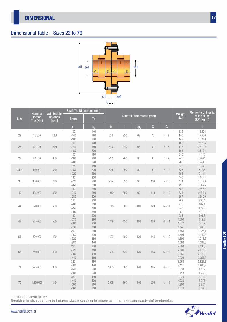
Dimensional Table – Sizes 22 to 79
* To calculate “J”, divide GD2 by 4.The weight of the hubs and the moment of inertia were calculated considering the average of the minimum and maximum possible shaft bore dimensions.
Size
Nominal Torque
Tna (Nm)
Admissible Rotation
[rpm]
Shaft Tip Diameters (mm)
General Dimensions (mm) Weight (kg)
Momento of Inertia of the HubsGD2 (kgm2)From To
e1 e1 df i ep1 C G 1 1
22 39.000 1.200100
>140 >180
140 180 200
558 220 68 70 4 ~ 8132 140 142
16,326 17,720 18,440
25 52.000 1.050100 >140 >180
140 180 200
635 240 68 80 4 ~ 8168 177 191
26,596 28,292 31,404
28 84.000 950100
>160 >200
160 200 240
712 260 80 80 5 ~ 9240 245 260
48,80 50,64 54,80
31,5 110.000 850125 >180 >220
180 220 260
800 290 80 90 5 ~ 9322 328 353
81,80 84,68 91,84
36 150.000 750140
>220 >260
220 260 290
905 320 90 100 5 ~ 10440 474 496
144,44 153,28 164,76
40 195.000 680150 >240 >280
240 280 320
1010 350 90 110 5 ~ 10582 625 657
235,52 248,68 264,20
44 270.000 600
160 >200 >250 >300
200 250 300 350
1118 380 100 120 6 ~ 11
763 775 842 882
395,4 402,4 424,8 449,2
49 345.000 550
180 >230 >280 >330
230 280 330 380
1248 420 100 130 6 ~ 11
983 1.000 1.077 1.141
601,6 613,2 645,2 684,0
55 530.000 490
200 >260 >320 >380
260 320 380 440
1402 480 120 145 6 ~ 12
1.469 1.494 1.609 1.692
1.126,4 1.149,6 1.213,2 1.289,6
63 750.000 430
260 >320 >380 >440
320 380 440 480
1604 540 120 165 6 ~ 12
2.068 2.109 2.261 2.328
2.030,8 2.079,2 2.175,2 2.254,8
71 975.000 380
320 >380 >440 >500
380 440 500 540
1805 600 140 185 8 ~ 16
3.063 3.111 3.333 3.413
3.821,2 3.900,8 4.112 4.240
79 1.300.000 340
380>440 >500 >560
440 500 560 600
2006 660 140 200 8 ~ 16
3.970 4.030 4.300 4.370
5.840 5.976 6.324 6.468
ep1 ep1
ødf øe1 øe1CC C C
I I
G
www.henfel.com.br
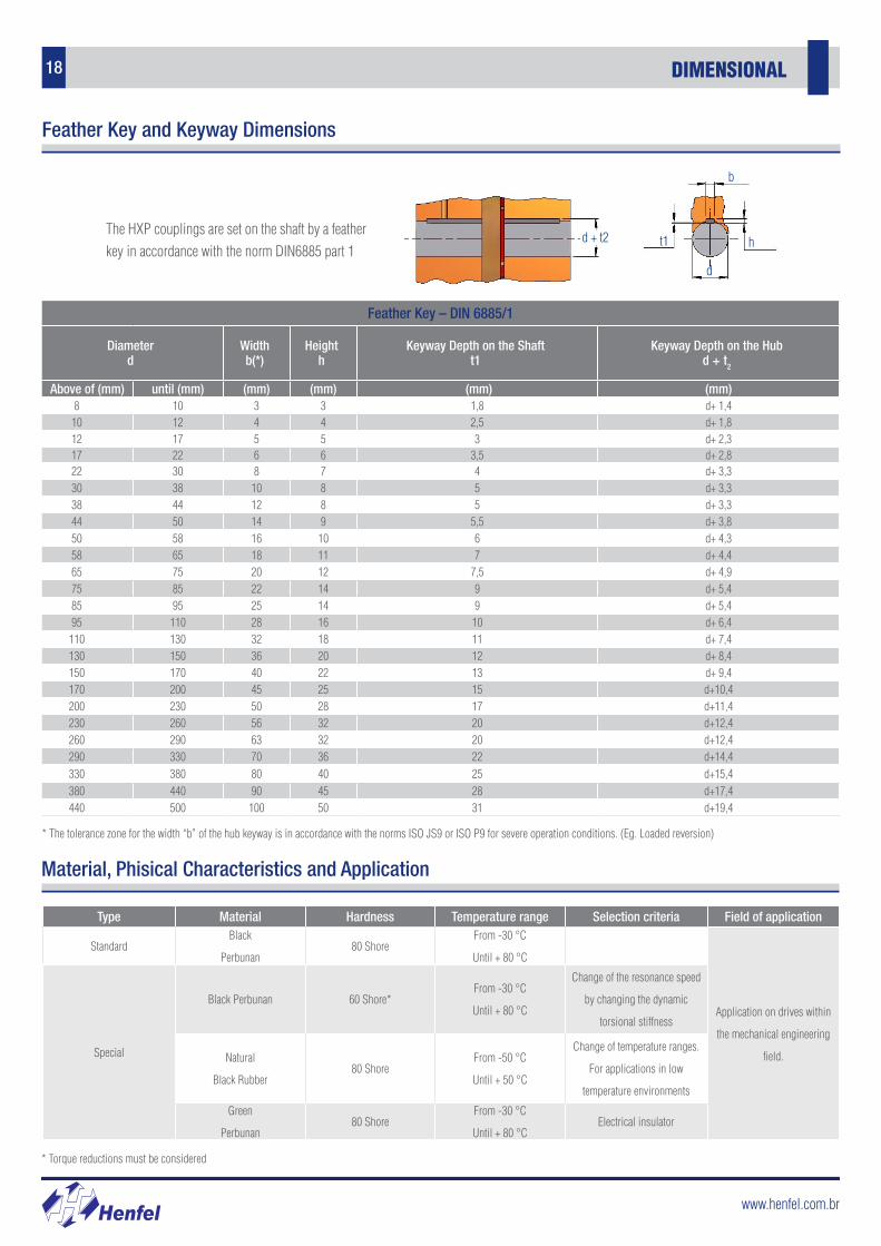
18 DIMENSIONAL
Feather Key – DIN 6885/1
Diameterd
Widthb(*)
Heighth
Keyway Depth on the Shaftt1
Keyway Depth on the Hubd + t2
Above of (mm) until (mm) (mm) (mm) (mm) (mm)8 10 3 3 1,8 d+ 1,410 12 4 4 2,5 d+ 1,812 17 5 5 3 d+ 2,317 22 6 6 3,5 d+ 2,822 30 8 7 4 d+ 3,330 38 10 8 5 d+ 3,338 44 12 8 5 d+ 3,344 50 14 9 5,5 d+ 3,850 58 16 10 6 d+ 4,358 65 18 11 7 d+ 4,465 75 20 12 7,5 d+ 4,975 85 22 14 9 d+ 5,485 95 25 14 9 d+ 5,495 110 28 16 10 d+ 6,4110 130 32 18 11 d+ 7,4130 150 36 20 12 d+ 8,4150 170 40 22 13 d+ 9,4170 200 45 25 15 d+10,4200 230 50 28 17 d+11,4230 260 56 32 20 d+12,4260 290 63 32 20 d+12,4290 330 70 36 22 d+14,4330 380 80 40 25 d+15,4380 440 90 45 28 d+17,4440 500 100 50 31 d+19,4
* The tolerance zone for the width “b” of the hub keyway is in accordance with the norms ISO JS9 or ISO P9 for severe operation conditions. (Eg. Loaded reversion)
Feather Key and Keyway Dimensions
The HXP couplings are set on the shaft by a feather key in accordance with the norm DIN6885 part 1
d + t2 ht1
b
d
Type Material Hardness Temperature range Selection criteria Field of application
StandardBlack
Perbunan80 Shore
From -30 °C
Until + 80 °C
Application on drives within
the mechanical engineering
field.Special
Black Perbunan 60 Shore*From -30 °C
Until + 80 °C
Change of the resonance speed
by changing the dynamic
torsional stiffness
Natural
Black Rubber80 Shore
From -50 °C
Until + 50 °C
Change of temperature ranges.
For applications in low
temperature environments
Green
Perbunan80 Shore
From -30 °C
Until + 80 °CElectrical insulator
Material, Phisical Characteristics and Application
* Torque reductions must be considered
www.henfel.com.br
19
Henf
lex
HDF
Henf
lex
HXP
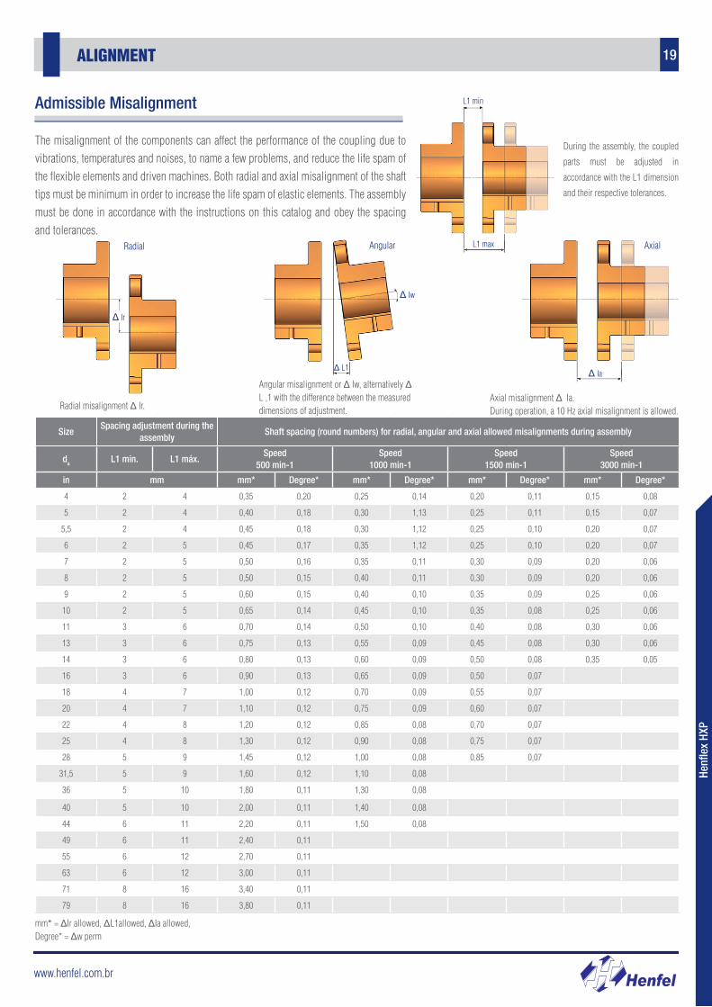
ALIGNMENT
The misalignment of the components can affect the performance of the coupling due to vibrations, temperatures and noises, to name a few problems, and reduce the life spam of the flexible elements and driven machines. Both radial and axial misalignment of the shaft tips must be minimum in order to increase the life spam of elastic elements. The assembly must be done in accordance with the instructions on this catalog and obey the spacing and tolerances.
SizeSpacing adjustment during the
assemblyShaft spacing (round numbers) for radial, angular and axial allowed misalignments during assembly
da L1 min. L1 máx.Speed
500 min-1Speed
1000 min-1Speed
1500 min-1Speed
3000 min-1
in mm mm* Degree* mm* Degree* mm* Degree* mm* Degree*
4 2 4 0,35 0,20 0,25 0,14 0,20 0,11 0,15 0,08
5 2 4 0,40 0,18 0,30 1,13 0,25 0,11 0,15 0,07
5,5 2 4 0,45 0,18 0,30 1,12 0,25 0,10 0,20 0,07
6 2 5 0,45 0,17 0,35 1,12 0,25 0,10 0,20 0,07
7 2 5 0,50 0,16 0,35 0,11 0,30 0,09 0,20 0,06
8 2 5 0,50 0,15 0,40 0,11 0,30 0,09 0,20 0,06
9 2 5 0,60 0,15 0,40 0,10 0,35 0,09 0,25 0,06
10 2 5 0,65 0,14 0,45 0,10 0,35 0,08 0,25 0,06
11 3 6 0,70 0,14 0,50 0,10 0,40 0,08 0,30 0,06
13 3 6 0,75 0,13 0,55 0,09 0,45 0,08 0,30 0,06
14 3 6 0,80 0,13 0,60 0,09 0,50 0,08 0,35 0,05
16 3 6 0,90 0,13 0,65 0,09 0,50 0,07
18 4 7 1,00 0,12 0,70 0,09 0,55 0,07
20 4 7 1,10 0,12 0,75 0,09 0,60 0,07
22 4 8 1,20 0,12 0,85 0,08 0,70 0,07
25 4 8 1,30 0,12 0,90 0,08 0,75 0,07
28 5 9 1,45 0,12 1,00 0,08 0,85 0,07
31,5 5 9 1,60 0,12 1,10 0,08
36 5 10 1,80 0,11 1,30 0,08
40 5 10 2,00 0,11 1,40 0,08
44 6 11 2,20 0,11 1,50 0,08
49 6 11 2,40 0,11
55 6 12 2,70 0,11
63 6 12 3,00 0,11
71 8 16 3,40 0,11
79 8 16 3,80 0,11
mm* = ΔIr allowed, ΔL1allowed, ΔIa allowed, Degree* = Δw perm
During the assembly, the coupled
parts must be adjusted in
accordance with the L1 dimension
and their respective tolerances.
Admissible Misalignment
Δ Ir
Δ Iw
Radial Axial
Δ L1 Δ Ia
Angular
L1 min
L1 max
Radial misalignment Δ Ir.
Angular misalignment or Δ Iw, alternatively Δ L ,1 with the difference between the measured dimensions of adjustment.
Axial misalignment Δ Ia.During operation, a 10 Hz axial misalignment is allowed.
www.henfel.com.br
20 ALIGNMENT
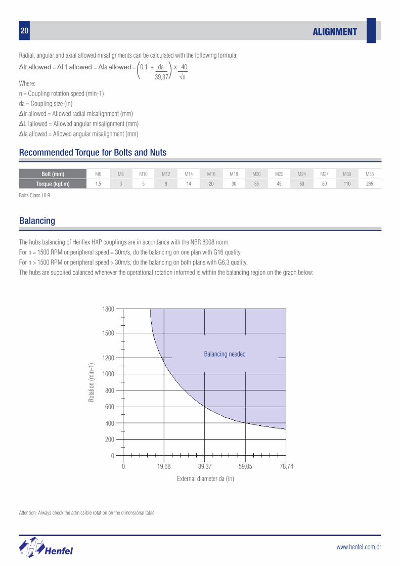
Radial, angular and axial allowed misalignments can be calculated with the following formula:
Recommended Torque for Bolts and Nuts
Bolts Class 10.9
Where: n = Coupling rotation speed (min-1)da = Coupling size (in)ΔIr allowed = Allowed radial misalignment (mm)ΔL1allowed = Allowed angular misalignment (mm)ΔIa allowed = Allowed angular misalignment (mm)
Bolt (mm) M6 M8 M10 M12 M14 M16 M18 M20 M22 M24 M27 M30 M36
Torque (kgf.m) 1,5 3 5 9 14 20 30 35 45 60 80 110 265
Balancing
The hubs balancing of Henflex HXP couplings are in accordance with the NBR 8008 norm.For n = 1500 RPM or peripheral speed = 30m/s, do the balancing on one plan with G16 quality.For n > 1500 RPM or peripheral speed > 30m/s, do the balancing on both plans with G6,3 quality.The hubs are supplied balanced whenever the operational rotation informed is within the balancing region on the graph below:
Balancing needed
1800
1500
1200
1000
800
600
400
200
0
0 19,68 39,37 59,05 78,74
External diameter da (in)
Rotat
ion
(min
-1)
Attention: Always check the admissible rotation on the dimensional table.
ΔIr allowed = ΔL1 allowed = ΔIa allowed = 0,1 + da x 40 39,37 √n( )