Embed Size (px)
Citation preview
Valtek Electro-pneumaticTransducers
2
Valtek Electro-pneumatic Transducer
Flowserve Corporation, Valtek Control Products, Tel. USA 801 489 8611
Features
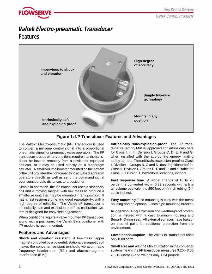
Impervious to shockand vibration
Intrinsically safeand explosion-proof
Figure 1: I/P Transducer Features and Advantages
Mounts in anyposition
Simple two-wiretechnology
High degreeof accuracy
The Valtek® Electro-pneumatic (I/P) Transducer is usedto convert a milliamp control signal into a proportionalpneumatic signal for pneumatic valve operators. The I/Ptransducer is used when conditions require that the trans-ducer be located remotely from a positioner equippedactuator, or it may be used directly on a diaphragmactuator. A small volume booster mounted on the bottomof the unit provides the flow capacity to actuate diaphragmoperators directly as well as send the command signalover considerable distances to a positioner.
Simple in operation, the I/P transducer uses a stationarycoil and a moving magnet with low mass to produce asmall-size unit, that may be mounted in any position. Ithas a fast response time and good repeatability, with ahigh degree of reliability. The Valtek I/P transducer isintrinsically safe and explosion proof. Its calibration sys-tem is designed for easy field adjustment.
When conditions require a valve mounted I/P transducer,along with a positioner, the Valtek Beta positioner withI/P module is recommended.
Features and AdvantagesShock and vibration resistant A low-mass flappermagnet controlled by a powerful, stationary magnetic coilmakes the converter resistant to shock, vibration, radiofrequency interference (RFI) and electro-magneticinterference (EMI).
Intrinsically safe/explosion-proof The I/P trans-ducer is Factory Mutual approved and intrinsically safefor Class I, II, III, Division I, Groups C, D, E, F and G,when installed with the appropriate energy limitingsafety barriers. The unit is also explosion-proof for ClassI, Division I, Groups B, C and D; dust-ingnitionproof forClass II, Division I, Groups E, F and G; and suitable forClass III, Division 1, hazardous locations, indoors.
Fast response time A signal change of 10 to 90percent is converted within 0.32 seconds with a lineair volume equivalent to 250 feet of 1/4-inch tubing (6.4cubic inches).
Easy mounting Field mounting is easy with the metalhousing and an optional 2-inch pipe mounting bracket.
Rugged housing Explosion and weather-proof protec-tion is insured with a cast aluminum housing andBuna-N O-ring seal. All external surfaces have baked-on enamel paint for additional protection from theenvironment.
Low air consumption The Valtek I/P transducer usesonly 0.08 scfm.
Small size and weight Miniaturization in the convertersystem means the I/P transducer measures 3.25 x 3.00x 5.12 (inches) and weighs only 1.34 pounds.
3
Valtek Electro-pneumatic Transducer
Flowserve Corporation, Valtek Control Products, Tel. USA 801 489 8611
Table I: Specifications
Input range 4-20 mA
Input resistance Approximately 200 ohms
Capacitance Negligible
Output range 3-15 psi
Output characteristic Linear, direct or reverse
Air capacity 1.6 scfm
Air supply (maximum) 20 psi, + 1.5 psi (oil, waterand dust-free)
Steady state air 0.08 scfmconsumption
Linearity < 0.5%
Hysteresis < 0.3%
Response threshold < 0.1%
Temperature influence < 0.05% ° F
Air supply influence < 0.3%/1.5 psi
Position influence < 0.5%
Vibration influence < 0.5% for an acceleration< 10 G’s and a frequency< 80 Hz
Influence of interfering Not measurableradiation
Response time 10-90% or 90-10% = 0.3seconds with a volumeof 6.05 cubic inches
10-90% = 1.5 secondswith a volume of 60.5cubic inches
90-10% = 2.5 secondswith a volume of 60.5cubic inches
Ambient temperature -20° F to +180° Flimits
Connections – Air 1/8-inch NPT – Electrical 1/2-inch NPT
Weight (pounds) 1.34
Specifications / Ordering
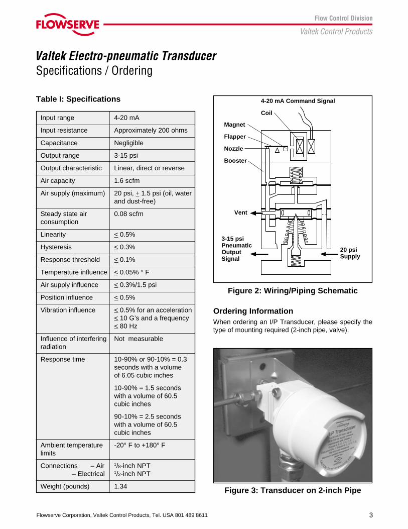
Figure 3: Transducer on 2-inch Pipe
Figure 2: Wiring/Piping Schematic
Ordering InformationWhen ordering an I/P Transducer, please specify thetype of mounting required (2-inch pipe, valve).
4-20 mA Command Signal
Coil
Magnet
Flapper
Nozzle
Booster
3-15 psiPneumaticOutputSignal
Vent
20 psiSupply
4
Valtek Electro-pneumatic Transducer
Flowserve Corporation, Valtek Control Products, Tel. USA 801 489 8611
Dimensions
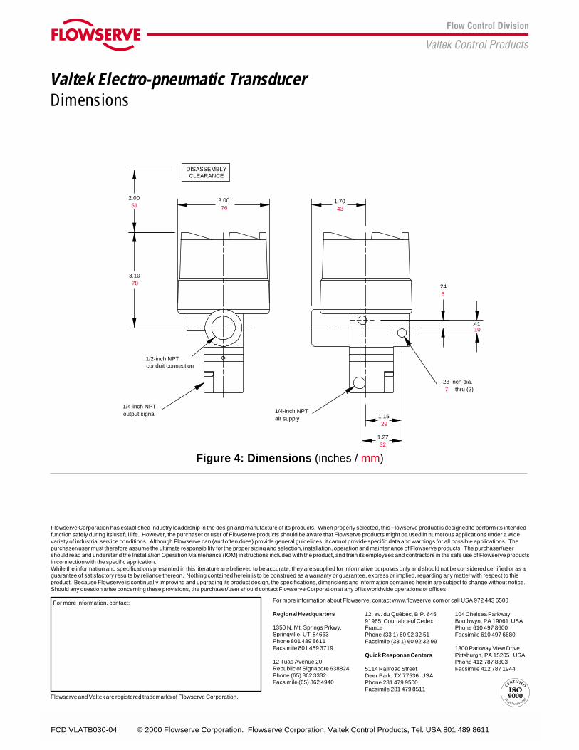
.28-inch dia.thru (2)
1/2-inch NPTconduit connection
1/4-inch NPTair supply
1/4-inch NPToutput signal
DISASSEMBLYCLEARANCE
3.0076
1.7043
3.1078
2.0051
.4110
1.1529
1.2732
.246
7
Figure 4: Dimensions (inches / mm)
FCD VLATB030-04 © 2000 Flowserve Corporation. Flowserve Corporation, Valtek Control Products, Tel. USA 801 489 8611
Flowserve Corporation has established industry leadership in the design and manufacture of its products. When properly selected, this Flowserve product is designed to perform its intendedfunction safely during its useful life. However, the purchaser or user of Flowserve products should be aware that Flowserve products might be used in numerous applications under a widevariety of industrial service conditions. Although Flowserve can (and often does) provide general guidelines, it cannot provide specific data and warnings for all possible applications. Thepurchaser/user must therefore assume the ultimate responsibility for the proper sizing and selection, installation, operation and maintenance of Flowserve products. The purchaser/usershould read and understand the Installation Operation Maintenance (IOM) instructions included with the product, and train its employees and contractors in the safe use of Flowserve productsin connection with the specific application.While the information and specifications presented in this literature are believed to be accurate, they are supplied for informative purposes only and should not be considered certified or as aguarantee of satisfactory results by reliance thereon. Nothing contained herein is to be construed as a warranty or guarantee, express or implied, regarding any matter with respect to thisproduct. Because Flowserve is continually improving and upgrading its product design, the specifications, dimensions and information contained herein are subject to change without notice.Should any question arise concerning these provisions, the purchaser/user should contact Flowserve Corporation at any of its worldwide operations or offices.
For more information, contact: For more information about Flowserve, contact www.flowserve.com or call USA 972 443 6500
Regional Headquarters
1350 N. Mt. Springs Prkwy.Springville, UT 84663Phone 801 489 8611Facsimile 801 489 3719
12 Tuas Avenue 20Republic of Signapore 638824Phone (65) 862 3332Facsimile (65) 862 4940
Flowserve and Valtek are registered trademarks of Flowserve Corporation.
12, av. du Québec, B.P. 64591965, Courtaboeuf Cedex,FrancePhone (33 1) 60 92 32 51Facsimile (33 1) 60 92 32 99
Quick Response Centers
5114 Railroad StreetDeer Park, TX 77536 USAPhone 281 479 9500Facsimile 281 479 8511
104 Chelsea ParkwayBoothwyn, PA 19061 USAPhone 610 497 8600Facsimile 610 497 6680
1300 Parkway View DrivePittsburgh, PA 15205 USAPhone 412 787 8803Facsimile 412 787 1944