Embed Size (px)
Citation preview
The 30th International Electric Propulsion Conference, Florence, Italy
September 17-20, 2007
1
Validation Status of the PICPluS Plume Simulation and Spacecraft Interaction Tools: Lesson Learnt from Flight and
Ground Experimental Data
IEPC-2007-325
Presented at the 30th International Electric Propulsion Conference, Florence, Italy September 17-20, 2007
A. Passaro*, A.Vicini†, and F. Nania‡
Alta SpA, Pisa, 56121, Italy
Abstract: The PICPlus code family is a set of 2D and 3D PIC/DSMC codes which is used to predict the parameters of EP plumes and their interaction with the surrounding environment during ground tests and flight application. The codes are under continuous development and improvement, as more information and validation data become available from various sources. During 2005 and 2006 a large impulse to the validation activities came from the flight data from the SMART-1 mission by ESA, in which Alta was involved as part of the spacecraft interaction working group. This information allowed to further improve the prediction capability of the codes with respect to actual flight environmental conditions. At the same time, a number of test campaigns were performed in Alta’s ground facilities, for both Hall effect thrusters and ion engines. Also in this case PICPlus was used to predict the behaviour of the thrusters plume, with special attention to the facility sputtering phenomena and thrusters back-contamination. Results from these tests were also incorporated in the code.
The paper will present the improvements which occurred to PICPlus during 2006 and the first half of 2007, and will show how the codes were used in prediction/correction iterations for ground tests in order to extend their capability and accuracy.
Nomenclature C = capacitance e = electron charge E = secondary electrone energy k = Boltzman constant I = current n = number density N = shape function N = shape function vector P = probability r = position vector T = temperature Vd = discharge potential ε, ε0 = dielectric constant/ incident electron energy ρ = charge density
* Project Manager, Industrial Services, [email protected]. † Aerospace Engineer, Industrial Services, [email protected]. ‡ Engineer, MSc, Industrial Services, [email protected].
Φ, φ = electric scalar potential φ = nodal electric potential vector Ω = calculation domain/ solid angle ∂Ω = calculation domain boundary σ = secondary electron emission coefficient θ = particle incidence angle for surface impact
I. Introduction lectric propulsion represents one of the most promising technologies for application in future space missions. In the recent years the first western missions have seen successful use of Gridded Ion Engines (Deep Space 1,
Artemis) and Hall Effect Thrusters (SMART-1): nonetheless, at the present state of knowledge, a substantial effort for the complete characterization of the interaction between thruster and spacecraft is still needed.
E As the European SMART-1 mission proved1, although the possible negative interaction between the electric propulsion system and the spacecraft is very limited, a number of complex phenomena arises due to the extensive use of the propulsion system in orbit (e.g. interaction between the plume and the solar array orientation, leading to complex patterns for the spacecraft floating potential). At the same time, before the application in flight, a very detailed on-ground characterization has to be performed: also in this case the need to decouple the complex interaction phenomena that happen between the thruster and the vacuum chamber is of fundamental importance in order to correctly design the thruster itself. A complete 3D simulation is desirable to try to exploit this kind of phenomena with a realistic description of the involved geometries, as well as a complete particle approach, i.e. use of electron particles as well as neutral and ion particles, so that a detailed plasma-surface interaction model can be obtained. During the last few years, Alta SpA has developed a series of plume simulation tools based on the particle in cell approach that are included in the PICPluS code family.
This paper will describe briefly the PICPluS codes family, considering the implemented physical models, numerical description of the domain, verification and validation activities with on-ground data the SMART-1 case.
It will successively focus on the latest improvement implemented in the codes in order to use all of the lessons learned during the last few year of validation activity.
II. The PICPluS code family The PICPluS code family is a composed by two and three-dimensional hybrid/full PIC codes, developed at Alta
since 20024-8. The codes allow to perform time accurate plasma plume/spacecraft interaction simulations in four different ways:
• Full particle simulation on a multi-block grid composed by Cartesian structured boxes with external solid surfaces (Fig. 2).
• Full particle simulation on a general non-structured grid including surfaces and solid bodies (Fig. 7)
• Quasi-neutral particle simulation on a non-uniform structured grid including surfaces and solid bodies (Fig. 1).
• Quasi-neutral particle simulation on a general non-structured grid including surfaces and solid bodies.
Hall Effect Thruster, Gridded Ion Engines and FEEP thrusters can be simulated, while the application of the code to MPD is presently underway. In the unstructured versions multiple thrusters firing simultaneously can be simulated and thrust steering devices effects can be studied.
The 30th International Electric Propulsion Conference, Florence, Italy
September 17-20, 2007
2

The 30th International Electric Propulsion Conference, Florence, Italy
September 17-20, 2007
3
Typically, the plume is simulated starting from the thruster outlet using customizable inlet distributions. A general analytical model is used in order to statistically represent the desired distributions on the thruster exit for particle number density, position, and velocity vectors. The magnetic field can be added as a constant input field, allowing to perform the full thruster simulation, i.e. including the ionization regions, provided that a relatively small grid is used, in order to properly represent the Debye length. Finally, the code is written with the aim to use as many experimental data as possible for the input and is provided with internal advanced interpolation features (Fig. 3) to produce the proper input files even starting from data on a small set of points.
In the case of the completely unstructured model, a first tentative of Object Orientation has been implemented for the grid, particle, species, sources, and wall treatment, choosing as primary class the tetrahedral/triangular cells and considering the internal particles and the external boundaries as additional properties of the cell. The main advantage of this approach is the significant speed up that is obtained for the particle find at each iteration.
The code is written entirely in FORTRAN and is windows based, with a user-friendly Graphic User Interface for the run set-up. Due to the different approaches and the related memory requirements, different amount of cells and particles can be simulated in sufficiently short times (typically one day of simulation on a standard single processor PC workstation), as indicated in Table 1.
Model Grid Type Maximum number of cells
Maximum number of particles
Structured hybrid Non uniform Cartesian with internal bodies
2·106 5·106
Unstructured hybrid Tetrahedrons 5·105 2·106 Full particle N Cartesian boxes N · 17·106 70·106 Full particle Unstructured 2·105 1·106
Table 1. PICPluS 3D typical limit parameters for runs on a single processor PC workstation.
Figure 1. PICPluS 3D SMART-1 geometry model and grid in the hybrid, non-uniform structured model.
Figure 2. PICPluS 3D generic grid for the full particle model (nested uniform Cartesian grids).
Figure 3. 3D injection probability distributions obtained for non axisymmetric inlet conditions.
A. Plasma Dynamics
1. Ions and Neutrals Several particle species can be independently simulated (neutral atoms, single and doubly charged ions). Xenon
and Caesium are currently used as propellants, but other propellants can be added. Background distributions of neutral propellant can be included in the simulation in order to simulate the vacuum chamber environment. Neutral atoms, possibly exiting from the thruster due to the effective ionization rate, can be also simulated (either through a MCC or DSMC approach).
2. Electrons If the full particle approach is used, electrons can be simulated as independent particles. Due to their low mass,
an extremely small time step (~10-11 s) has to be used in order to have them move by less of the cell reference length in a single step, as experience has proven that inaccurate results are obtained if a too big step is used. More in detail, the complete Poisson’s equation has to be solved necessarily at each electron time step, leading to the need of fast 3D solvers. Two additional techniques can be used to speed up the simulation: artificial decrease of the heavy particles mass, as indicated by Ref. 9, with the related decrease in the minimum required time step, and use of different time steps for each particle species, while preserving the time-accurate approach. The technique of modification of the vacuum permeability ε0 in order to increase the Debye length, also presented in Ref. 9, is not implemented in order not to sum non-linear correction effects that could modify the simulated physics.
3. Potential and electric field. For the quasi-neutral codes, the electric potential is obtained from the super-imposition of the instantaneous
potential field derived by the solid surfaces and the one created by the plasma. The plasma contribution to the total potential is obtained by the hypothesis of quasi-neutrality, and thus equaling the electron density to the ion density. Assuming that electrons in the plume are collision-less and un-magnetized, and that their pressure obeys the ideal gas law, the Boltzmann relation is obtained for the plasma potential:
)ln( **
nn
ekT
=− ϕϕ (1)
where the superscript * indicates the reference state. Electron temperature in eq.(1) may be held constant. However, as experimental evidence indicates that electron temperature is not constant, an adiabatic model10 can be used to relate its changes to changes in electron density at each time step.
For the full particle code, at each time step the complete Poisson’s equation is solved considering ions and electrons density as well as the instantaneous values of potential on the surfaces. For the multi-block Cartesian grid code, the solver is a standard 3D multigrid routine, with uniform spacing on each direction (but not necessarily equal on the three axis), optimised for speed. For the unstructured codes the Poisson solver is described in section V.A..
For all models the spacecraft (solid surface) floating potential calculation is performed, at each time step,
considering that its value is the one that implies a net current flux on that surface element equal to zero:
Iionic + Ielectronic = 0 (2)
Several components can be considered both for the ionic and electronic parts of Eq. (2) as such, thermal, space ambient (including possible ram and wake effects), primary beam, and backflow components. Moreover, a more detailed simulation of each surface element can be imposed defining its properties in the pre-processing phase (e.g. constant potential, partial current flux entering, internal connection with other elements etc.), as described in section V.B.
For the structured grid based simulations, the electric field is obtained through spatial differentiation of the
plasma potential. For the unstructured grid case, the electric field is obtained on the grid nodes by computing the potential gradient: to this purpose, a least-squares technique is used. The least-squares gradient reconstruction procedure originally developed by Barth11 is based on approximating the variation of a dependent variable φ along an edge linking vertices 0 and i by a truncated Taylor series, e.g., for a linear approximation,
φi = φ0 + (∇φ)0 • Δr0i, 1 ≤ i ≤ d0 (3)
The 30th International Electric Propulsion Conference, Florence, Italy
September 17-20, 2007
4

The 30th International Electric Propulsion Conference, Florence, Italy
September 17-20, 2007
5
Where Δr0i=ri-r0 and r are the position vectors. We define by d0 the degree of vertex 0, i.e. the number of neighbours included in the gradient reconstruction at vertex 0. The application of Eq. (3) to all edges incident to vertex 0 gives a system of linear equations for the derivatives at vertex 0, with a d0 × n0 matrix of geometrical terms, (n0 derivatives, d0 function values). Since the degree is usually larger than the number of derivatives reconstructed, the system is solved in a least-squares fashion. 4. Virtual probes and diagnostics
Virtual RPA and Faraday cup rakes can be placed anywhere in the flow-field, assigning to each probe its real dimension and normal vector. In the unstructured grid it is possible to assign to the probes also solid properties (surface mesh, surface temperature and potential), although with a penalty on simulation speed, due to the heavier grid. Additional diagnostics include the computation of integral thruster performance parameter (thrust, discharge current) as well distributions on all of the solid surfaces (impacts, currents, sputtering etc.) and the calculation of population parameters such as, for example, the electron energy distribution function.
B. Particle approach
1. Computational Grid and multi-block approach For both the constructed grid based simulations, the grid is generated by simple input screens in the code GUI before the beginning of the simulation and successively stored in an output file for review. The PICPluS pre-processor therefore calculates a set of useful parameters as the grid spacing (non uniform) and the boundary elements (internal and external surfaces). For the unstructured based simulation, the mesh can be generated using any available dedicated software and then fed to PICPluS3DF pre-processor. The present code version uses as the default input grids produced by the code GMSH12. After reading the list of nodes coordinates and connectivity, a number of quantities is computed and stored to make the grid usable by the PIC code. The most important among these can be summarized by the following actions:
1) Identification and label of each single face as internal or boundary (outflow, wall, source, etc.); 2) For each tetrahedron, find the list of all neighbour cells (i.e. all the cells that have at least one node in
common with it); 3) For each node, find the list of all neighbour nodes (i.e. all the nodes connected with it through an edge);
All these operations are done only once for each mesh in the pre-processing phase, and the relevant data are stored in a grid file which is an input for the PIC code.
2. Particle search For the structured grid based models, the particle search phase is almost automatic, due to the simple analytical
relations that relate any point in the domain with the correspondent cell. Instead, a more complex algorithm is needed in order to individuated the cell containing a determined particle in the unstructured case; obviously a simple loop on each cell is sufficient but extremely time consuming and therefore to be avoided, if possible. To this regard an Object Orientation character is given to the code regarding the grid and particle treatment. The label of the cell containing each single simulated particle is computed and stored at each time step as a particle property. After injection, the cell containing the new particle is searched among those having one face on the thruster exit. The volume of the 3 tetrahedrons obtained by connecting the particle with the 4 nodes of a cell are computed; if the sum of these 3 volumes differs from the volume of the considered cell by less than a specified tolerance, the particle belongs to that cell. After the generic time step, each particle is first searched in the cell where it was at the beginning of that time step; if the particle is not found in that cell, the “volume residual” procedure described above is carried out for each of the neighbour cells, and the particle is assigned to the cell where the residual has the minimum value. Of course particular cases (particle exiting from the simulation domain, hitting a solid wall etc.) are treated accordingly.
3. Collision Dynamics Neutral-neutral, neutral-electron, and ion-neutral (elastic and Charge Exchange) collisions can be included in the
PIC cycle independently, while electron-electron and electron-ion collisions are usually treated via an analytical MCC model. Typically the Variable Hard Sphere (VHS)13,14 model is employed, while, for Xenon atom-ion
The 30th International Electric Propulsion Conference, Florence, Italy
September 17-20, 2007
6
collisions, also the induced dipole model of Nanbu15 can be used; in the latter case, no collision cross sections need to be modeled.
4. Boundary conditions The boundaries of the simulation domain can be considered as outflow or as solid walls; in the latter case their
initial temperature and potential are assigned and can be kept constant during the simulation; if the unsteady simulation is chosen the values are updated at each time step. Particle impacts may range between perfect reflection and full random diffusion, with partial thermal accommodation calculated using Cercignani-Lampis-Lord model14. In the same manner internal solid boundaries can be modeled. Regarding the Poisson’s equation solution, boundary condition are the classical DiRichlet, Neumann and mixed condition.
III. Code verification and validation The single code models have been verified and validated in the last few years considering data available from
literature and from internal tests at Alta. Application of the code to flight data was carried out within the SMART-1 Plasma Working Group lead be ESA. Table 2 recaps the main test cases used for validation. Generally speaking, a good agreement was achieved for what concerns thrust, ion beam current, and ion current densities up to 90° from thruster exit.
B. Thruster simulation 1. SPT-100
Data measured by King17, Manzella18 and Kim16 were satisfactorily reproduced using a single set of injection conditions by PICPluS 3D code as shown on Fig. 4. The difference on beam current density between 3D data and experiment at high angles is due to the long computation times needed for a three-dimensional simulation to fill the whole domain, in particular in the back-flow region. In fact, one of the key differences between axi-symmetric and 3D structured simulations seems to be due to the fact that, in order to limit the computation time and the number of simulated particles, a coarser grid is necessary for 3D simulations, forcing therefore some (limited) grid effects on the results. From a physical point of view it appears that, for an axi-symmetric simulation, slightly higher levels of electron temperature are obtained in the near field w.r.t to the 3D results, starting from exactly the same initial conditions.
2. PPS®1350 Data measured during a ground test of the PPS®1350 were made available by SNECMA for a Faraday’s cup rake situated at 0.65 m from the thruster exit and run with a probe bias of some Volts. Of course, as already mentioned by Van Gilder and Boyd in Ref. 19, the most important parameter determining plume behavior appears to be the inlet distributions used for ion injection: starting from the SPT-100 typical inlet distributions it was possible to identify the injection parameters able to best reproduce the experimental data, obviously including a proper probe bias, that were then used for 2D and 3D simulations. The two codes results agree fairly well (Fig. 5) for what concerns the simulation in ground conditions while a certain discrepancy (about 5 deg) can be individuated in simulation for flight conditions at angles greater than 30 deg, due to the heavy effect that, in this case, is played by the electron temperature model.
3. Unsteady Hall Thruster Plume simulation
A full 3D particle simulation was carried out in order to analyze the neutralization process of an Hall Thruster plume in a realistic condition8. The simulation domain was constituted by a Cartesian box of roughly 0.5x0.5x0.5 m3; about 7 million particles per species (Xe+ and e-) were simulated with ions coming from the channel with the distribution used for the PPS-1350 thruster and electrons coming from an external hollow cathode. Moreover, electrons were simulated considering different thermal collision rates (i.e. internal re-distribution of the energy acquired between the real particles represented by the single simulated macro-particles) as well as using a ghost reservoir on the outside of the simulation domain to avoid the information loss due to electrons leaving the domain in the early stages of the simulation.

The results showed a number of peculiar effects, typical of the neutralization problem like the formation of a virtual cathode formed in the symmetrical position, with respect to the thruster axis, of the real one, fluctuations of electron in space and time, with frequencies in the range 1kHz-1MHz, even in the thruster azimuthal plane.
Thruster Model
Vd
[V]
Id
[A]
Anode MasFlow-rate
[mg/s]
BackgroundPressure [mbar]
Ref.
SPT-100 300 4.5 4.99 2.9⋅10-6 18
SPT-100 300 4.5 5.12 4⋅10-5 16
SPT-100 300 4.5 5.084 5.32⋅10-5 17
PPS-1350 350 3.47 4.21 1⋅10-4 - Alta XH5 350 11.16 9.2 8.32⋅10-5 23
MUSES-C 1500 0.14 0.21 2.0 ⋅10-6 20
The 30th International Electric Propulsion Conference, Florence, Italy
September 17-20, 2007
7
IV. Application to the SMART-1 mission SMART-1 was the first ESA Small Mission for
Advanced Research & Technology1, conceived to demonstrate the operation and the effectiveness of the Solar Electric Propulsion for deep space cruising in preparation of future ESA Cornerstone missions. Successfully launched on September 27th 2003, the SMART-1 satellite reached the Moon orbit on February 27th 2005 and its orbit period was extended due to a smaller than expected propellant usage up to that point. The monitoring of the operation/environment of the EP system, during the orbit transfer from GTO to the final lunar orbit, was retained a key issue related to the SMART-1 technology objectives: for this task a specific instrument, the Electric Propulsion Diagnostic Package (EPDP), was developed by LABEN Proel Tecnologie Division (LABEN/Proel)21. The EPDP provided information on the plasma environment near the thruster and was primarily intended to be operated, together with the thruster, during the spiralling escape manoeuvres around the Earth, and the capture of the Moon orbit.
A. Simulation results: comparison with flight data and analysis for the RPA
A set of numerical simulations was executed with the PICPluS on the satellite configurations shown in Fig. 7 and Fig. 9 with the hybrid structured and unstructured codes, using for all of the cases the standard injection conditions described in Ref. 6 and Ref. 7. The results were compared with the EPDP data considering a virtual RPA probe placed in the exact EPDP location, and comparing plasma features at the same place.
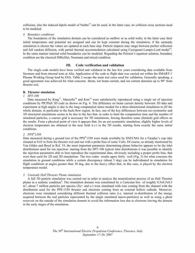
Looking the RPA flight data (Fig. 6) two peculiar features are evident: first of all the energy distribution presents a plateau after the primary peak with a long tail reaching energies up to 100 eV, compatible with the presence of a secondary peak situated about 20 V after the first. Secondarily, the primary peak seems to have a somewhat higher-than-expected energy while a peculiar absence of low energy impinging ions is noted.
Table 2. Validation test case matrix.
Figure 4. Comparison between 2D, 3D, and experimental data by King17 for the SPT-100 thruster in vacuum chamber conditions.
Figure 5. Comparison between 2D, 3D, and experimental data for the PPS-1350 thruster in vacuum chamber conditions.
The first set of simulations, conducted with the adiabatic model for electron temperature (with typical value of about 8 eV at the channel exit) produced a remarkably similar pattern for the RPA measurement although shifted by almost exactly 18 V towards lower energies. At the same time, it was noted from flight data that an almost constant gap of 18 V was present between RPA first peak position and the satellite floating potential. The explanation to this feature becomes evident considering that the RPA ground is given from the floating potential: incoming ions with energy in the plasma plume of about 18 eV are accelerated by an amount exactly equal to the floating potential by the RPA grid (summed with its sheath potential drop, that should be of some Volts) before being collected.
It was then decided to extend the investigation towards two different directions: assessment of the effect of the electron temperature model and actual value on the results, and assessment of the effect of the presence of Xe++ ions in the flow leaving the thruster.
For what concerns the electron temperature model effect it appeared that, using the adiabatic model, realistic values for Te and ion number density are obtained in the EPDP position compared to the flight data, with the unstructured code providing slightly lower values for both properties. It must be noted that the instrument seems to lay on the edge of the plasma plume and therefore be subjected to relatively high variations of ion number density (recorded values between 3.7⋅1013 and 7⋅1013 m-3). The possibility of EPDP location within the plasma sheath is consistent with the fact that the EPDP individuated a slightly non-neutral plasma. An increase in the Te reference value corresponds to a shift of the RPA peaks towards higher values with an overall broadening of the primary peak and an increasing separation of the two peaks; a significant part of low energy events is recorded in any case. The unstructured code predicts fairly well the first peak in the distribution, while overestimates the second of about 1.5 eV.
The use of a constant value for Te produces RPA distributions which are closer to the flight data for what concerns the low energy values but usually tend to present a too high secondary peak w.r.t the first one. Electron temperature value and relative potential are extremely different from the recorded ones, while ion number density is less than expected and close to the low limits for the adiabatic cases. An increase in the temperature value produces a significant shift of the peaks towards higher energies (as also noted by Boyd in Ref. 22).
Figure 6. Comparison between numerical results and flight data for the RPA measurements.
The 30th International Electric Propulsion Conference, Florence, Italy
September 17-20, 2007
8
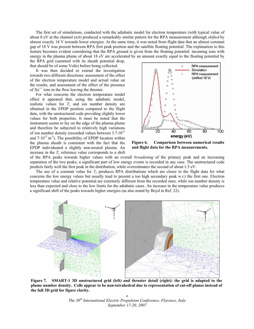
Figure 7. SMART-1 3D unstructured grid (left) and thruster detail (right): the grid is adapted to the plume number density. Cells appear to be non-tetrahedral due to representation of cut-off planes instead of the full 3D grid for figure clarity.

Summarizing these considerations it seems that the best way to reproduce the measured data is using the adiabatic Te model with a reference electron temperature between 8 and 12 eV, considering the shift to be imposed on the experimental data due to the grounding at the floating potential.
The effect of the double charged ions presence is evidenced in Fig. 8 where it can be noted that, if no Xe++ are simulated, the RPA profile is completely different from the flight one, while a percentage of at least 20% of Xe++ seems needed in order to reproduce the second peak and plateau features. This is in accord with basic theoretical calculations on thruster performance, that see as necessary a similar percentage of double charged ions in order to have the prescribed discharge current, voltage and thrust. On the other hand, the possibility of charge exchange collision involving double charged ions creating fast single charged ones could imply a different percentage of starting Xe++ ions.
Finally, it has to be noted that, as it was likely to be expected, the simulations for flight conditions predict a higher thrust level (up to +10%) than the one measured on ground and this feature has been observed consistently within the more than 2000 hours of firing of the thruster for the orbit raising.
Figure 8. Comparison between numerical results and flight data for the RPA measurements concerning the Xe++ population.
The 30th International Electric Propulsion Conference, Florence, Italy
September 17-20, 2007
9
modify the spacecraft potential).
h still lower in values (floating potential ranging between -20 and -15 V instead of the measured -33/-25 V range).
C. Interaction with the solar array and advanced simulations.
For the whole mission duration, a variation of the floating potential during each orbit was found with values ranging between -5 V and +10 V approximately w.r.t. the cathode reference potential. The feature appeared to be consistently related to the Solar Array orientation with respect to the sun, therefore indicating a possible interaction between the SA and the thruster plume. The SA presents a front side biased to +50 V and a back side with inter-connectors that aren’t shielded from the surrounding plasma. The situation was modeled with PICPluS with SA inclination angle varying by 30 deg increments. Moreover, different levels of potential shielding for the glass covered part were considered, as well a statistical simulation of the interconnectors was considered for the back side (i.e. they weren’t modeled on the actual geometry, but a given probability corresponding to the interconnector/solar panel area ratio was given to each particle impacting the back surface of the panel to actually
Figure 9. Floating potential advanced simulation: full satellite modeled with 30° oriented solar panels.
The results showed that, from the thruster point of view no appreciable difference in the plume is present; on the other hand, the plasma potential w.r.t. the imposed satellite potential varies with a trend similar to the measured one. The simulation with the more accurate description of the panel behavior led to variations in the floating potential consistent with the recorded pattern, althoug

Finally, a set of dedicated full 3D simulations was carried out as a first tentative to investigate about finer details like the plume oscillation and the non-neutral plasma individuated by the EPDP’s Langmuir probe.
A very simplified configuration was run with a box representing the satellite and the thruster, with electrons and ions moving with the electron time step (around 10-10 s). It was also found out that, in the EPDP position, and in general around solid surfaces, a slightly charge imbalance is present, possibly indicating the formation of a sheath region. The satellite tends to reach a floating potential slightly negative w.r.t. the plasma potential (about -5 V) as is indicated by the EPDP data. Also in this case more work is needed in order to increase the accuracy and maturity of the simulation.
V. Lessons learned and latest improvements on the codes The lessons learned from the SMART-1 simulation and from the latest ground tests carried out within Alta’s
facilities can be summarized in: - It is of fundamental importance to have the correct injection distribution in order to properly simulate
the plume: it is therefore highly desirable to have the possibility to simulate also the ionization regions. - It is very important to be able to correctly reproduce the satellite geometry as well as the correct Debye
length: unstructured simulations shall therefore be preferred. - Electron population behavior is one of the key aspect needed for a correct interpretation of the involved
phenomena: it is desirable to have full particle simulations. - The interaction of the plasma flow with solid walls dominates some of the most important phenomena
both on ground (sputtering and re-deposition) and in flight (rise of the floating potential): it is therefore desirable to have detailed plasma-surface interaction models.
These lessons led to the development of the code improvements described in the following subsections.
A. Fast unstructured Poisson solvers and application the HET channel simulation
The full particle channel simulation is realized presently with a 2D unstructured code using: - the Poisson solver described in the following subsection, realized in cooperation with the Department
of Electrical Engineering of the University of Bologna, - artificial decrease of neutral and ion masses (in order to reduce the needed number of time steps) - possibility of different time steps for each species and different weights for each particle - simulation of sheath formation on dielectric walls - secondary electron emission from the dielectric walls - MCC treated ion-electron and electron-electron collisions. - No anomalous electron transport
The 30th International Electric Propulsion Conference, Florence, Italy
September 17-20, 2007
10
Figure 10. Results of the thruster channel simulation for Alta X5H 5kw HET: ionization efficiency (left) and thrust (right). With respect to the experimental data the specific impulse from simulation is 30%lower

The code was applied first to the simulation of Alta’s XH5 5kW thruster23, considered as a challenging test case due to the high values of mass flow rate and discharge current of the thruster itself: the results were able to identify the main features of the flow comparing qualitatively well with on-ground observations of the macroscopic parameters. In particular an ionization efficiency of 86% was predicted leading to ion beam current of 6.7 A for 10 mg/s of propellant massflow, producing 123 mN of thrust. The calculated Isp is about 30% lower than the experimental one as well as the anode current is 40% lower than the recorded one; moreover, some anomalous behaviour of the potential field and of the wall properties was noted. The most probable reason from the numerical
point of view is the relatively low Debye length that is too small to be correctly reproduced with the allowed number of cells. Additionally, a more detailed study on the effects of plasma-wall interaction and electron transport models is underway. On the experimental side, a significant effect of the back-ground pressure was observed as well as a significant percentage of doubly charged ions that are not modeled yet in the simulation.
The code will be now used for the simulation of Alta’s HT-100 small HET24-26 that has received a more accurate characterization and provides a more favorable ration between Debye length and cell size. In both cases experimental data about the magnetic field were directly fed to PICPluS that interpolated the values on the grid nodes in its pre-processing phase.
Figure 11. Results of the thruster channel simulation for Alta X5H 5kw HET: non-dimensional radial magnetic field (left) and ion number density during discharge setup (right).
1. Poisson solver on unstructured grids (2D) Electrostatics is described by the Poisson equation:
0
2
ερϕ −=∇ (4)
The finite element discretization of the problem is based on the Galerkin weighted residual approach27. For an arbitrary test function W, a weak formulation of Eq. (4) is obtained:
( ) ∫∫∫ ΩΩ∂ΩΩ=Ω∂
∂∂
−Ω∇⋅∇ dWdn
WdW0ε
ρϕϕ
(5)
The discretization process is completed by expressing the unknown function ϕ by means of a set of shape function N. Taking W = N, an algebraic system is finally obtained.
sK =ϕ (6)The coefficient matrix of the system can be expressed as:
∫ ∇∇=Ω
ΩdT NNK
(7)
Thus, K depends only on the mesh topology. for the points internal to the calculation domain, the right hand side vector s is related to the charge density distribution:
The 30th International Electric Propulsion Conference, Florence, Italy
September 17-20, 2007
11
∫=Ω
Ωερ d
0
Ns
(8)
In order to implement boundary conditions involving the normal derivative of the electric potential (i.e. Neumann conditions), Eq. (8) has to be modified according to Eq. (5) for the points on the domain boundary.
The algebraic system in Eq. (6) is solved utilizing a GMRS algorithm, preconditioned by means of an ILUT strategy28.
B. Improved interaction with walls algorithms
The plasma interaction with the thruster, vacuum chamber, or satellite solid surfaces is the key phenomenon in order to properly model the thruster functioning or the satellite surface charging and floating potential. Due to this a significant amount of work is underway at Alta in order to include improved interaction-with-walls algorithms for the particle simulation without decreasing too much the computational speed of the code itself.
1. Surface charging
The improved surface charging treatment implemented in PICPluS is based on what described in Ref. 29 with the code allowing to user to specify a composite surface with dielectric and conductive layers able to reproduce, for instance, a typical solar panel element with glass on the surface and a conductive back-panel or inter-connector that leads to the internal spacecraft area. When an ion or electron hits the surface, its charge is first stored on the cells that make up the spacecraft surface and then, if needed, moved based on material properties and the local electric field inside the material. The surface potential is calculated based on the values of the internal potential, Φi, the surface charge qs, and the capacitance C of the surface element.
Cqs
is +Φ=Φ (9)
For a conducting surface, the charges collected will be distributed such that the surface potential is uniform. However, for a dielectric surface, the local surface potential is determined by local charge deposition from Eq. (9). In order to determine the local charge deposition qs and local surface potential Φs, one must first calculate the current conducted from the surface to the interior of the spacecraft as well as the current flowing along the surface. Once the currents are known, the spacecraft floating potential is determined from the total current balance including the plume components as indicated in Eq. 2.
2. Secondary electron emission
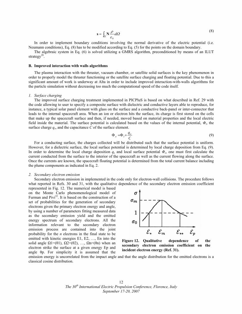
Secondary electron emission in implemented in the code only for electron-wall collisions. The procedure follows what reported in Refs. 30 and 31, with the qualitative dependence of the secondary electron emission coefficient represented in Fig. 12. The numerical model is based on the Monte Carlo phenomenological model of Furman and Pivi32. It is based on the construction of a set of probabilities for the generation of secondary electrons given the primary electron energy and angle, by using a number of parameters fitting measured data as the secondary emission yield and the emitted energy spectrum of secondary electrons. All the information relevant to the secondary electron emission process are contained into the joint probability for the n electrons in the final state to be emitted with kinetic energies E1, E2, …, En into the solid angle Ω1=(θ1), Ω2=(θ2), …, Ωn=(θn) when an electron strike the surface at a given energy Ep and angle θp. For simplicity it is assumed that the emission energy is uncorrelated from the impact angle and that the angle distribution for the emitted electrons is a classical cosine distr
Figure 12. Qualitative dependence of the secondary electron emission coefficient on the incident electron energy (Ref. 31).
ibution.
The 30th International Electric Propulsion Conference, Florence, Italy
September 17-20, 2007
12
3. Sputtering
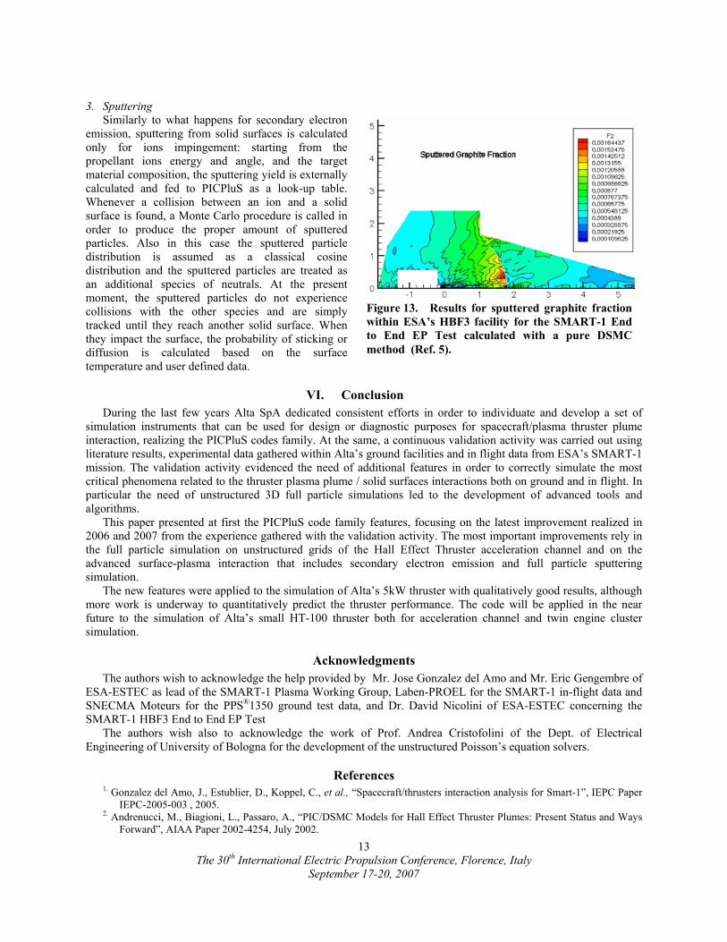
Similarly to what happens for secondary electron emission, sputtering from solid surfaces is calculated only for ions impingement: starting from the propellant ions energy and angle, and the target material composition, the sputtering yield is externally calculated and fed to PICPluS as a look-up table. Whenever a collision between an ion and a solid surface is found, a Monte Carlo procedure is called in order to produce the proper amount of sputtered particles. Also in this case the sputtered particle distribution is assumed as a classical cosine distribution and the sputtered particles are treated as an additional species of neutrals. At the present moment, the sputtered particles do not experience collisions with the other species and are simply tracked until they reach another solid surface. When they impact the surface, the probability of sticking or diffusion is calculated based on the surface temperature and user defined data.
Figure 13. Results for sputtered graphite fraction within ESA’s HBF3 facility for the SMART-1 End to End EP Test calculated with a pure DSMC method (Ref. 5).
VI. Conclusion During the last few years Alta SpA dedicated consistent efforts in order to individuate and develop a set of
simulation instruments that can be used for design or diagnostic purposes for spacecraft/plasma thruster plume interaction, realizing the PICPluS codes family. At the same, a continuous validation activity was carried out using literature results, experimental data gathered within Alta’s ground facilities and in flight data from ESA’s SMART-1 mission. The validation activity evidenced the need of additional features in order to correctly simulate the most critical phenomena related to the thruster plasma plume / solid surfaces interactions both on ground and in flight. In particular the need of unstructured 3D full particle simulations led to the development of advanced tools and algorithms.
This paper presented at first the PICPluS code family features, focusing on the latest improvement realized in 2006 and 2007 from the experience gathered with the validation activity. The most important improvements rely in the full particle simulation on unstructured grids of the Hall Effect Thruster acceleration channel and on the advanced surface-plasma interaction that includes secondary electron emission and full particle sputtering simulation.
The new features were applied to the simulation of Alta’s 5kW thruster with qualitatively good results, although more work is underway to quantitatively predict the thruster performance. The code will be applied in the near future to the simulation of Alta’s small HT-100 thruster both for acceleration channel and twin engine cluster simulation.
Acknowledgments The authors wish to acknowledge the help provided by Mr. Jose Gonzalez del Amo and Mr. Eric Gengembre of
ESA-ESTEC as lead of the SMART-1 Plasma Working Group, Laben-PROEL for the SMART-1 in-flight data and SNECMA Moteurs for the PPS®1350 ground test data, and Dr. David Nicolini of ESA-ESTEC concerning the SMART-1 HBF3 End to End EP Test
The authors wish also to acknowledge the work of Prof. Andrea Cristofolini of the Dept. of Electrical Engineering of University of Bologna for the development of the unstructured Poisson’s equation solvers.
References 1. Gonzalez del Amo, J., Estublier, D., Koppel, C., et al., “Spacecraft/thrusters interaction analysis for Smart-1”, IEPC Paper
IEPC-2005-003 , 2005. 2. Andrenucci, M., Biagioni, L., Passaro, A., “PIC/DSMC Models for Hall Effect Thruster Plumes: Present Status and Ways
Forward”, AIAA Paper 2002-4254, July 2002.
The 30th International Electric Propulsion Conference, Florence, Italy
September 17-20, 2007
13
The 30th International Electric Propulsion Conference, Florence, Italy
September 17-20, 2007
14
3. Biagioni, L., Passaro, A., Vicini, A., “Plasma Thruster Plume Simulation: Effect of the Plasma Quasi Neutrality Hypothesis”, 34th AIAA Plasmadynamics and Lasers Conference, Orlando FL , 23-26 June 2003.
4. Passaro , A., Vicini , A., Nania, F. and Biagioni, L., “Numerical Rebuilding of SMART-1 Plasma Plume-Spacecraft Interaction”, IEPC Paper IEPC-2005-174 , 2005.
5. Passaro, A., Vicini, A., and Biagioni L., “Plasma Thruster Plume Simulation: Effect of Vacuum Chamber Environment”, AIAA Paper 2004-2357, 35th AIAA Plasmadynamics and Lasers Conference, Portland OR , 28 June – 1 July 2004.
6. Passaro, A., Vicini, A., and Biagioni L., “3-D Computation of Plasma Thruster Plumes”, 40th AIAA/ASME/SAE/ASEE Joint Propulsion Conference & Exhibit, Fort Lauderdale – FL, 11-14 July 2004.
7. Passaro, A., Vicini, A., Nania, F., and Biagioni, L., “Numerical Rebuilding of SMART-1 Plasma Plume-Spacecraft Interaction”, IEPC-2005-174, 29th International Electric Propulsion Conference, Princeton University, October 31 – November 4, 2005.
8. Passaro, A., Nania, F., and Vicini, A., “Full 3D PIC simulation of Hall Effect Thrusters”, AIAA Paper 2006-3246, 37th AIAA Plasmadynamics and Lasers Conference, San Francisco CA, 5-8 June 2006.
9. Szabo, J. J., “Fully Kinetic Numerical Modeling of a Plasma Thruster”, Ph.D. Dissertation, Aeronautics and Astronautics Dept., Boston Univ., Cambridge, MA, 2001.
10. Celik, M., Santi, M., Cheng, S., Martinez-Sanchez, M., Peraire, J., “Hybrid-PIC Simulation of a Hall Thruster Plume on an Unstructured Grid with DSMC Collisions”, presented at the 28th IEPC, Toulouse, March 2003.
11. Barth, T.J., “A 3D Upwind Euler solver for unstructured meshes”, AIAA Paper 91-1548. 12. Geuzaine, C., Remacle, J.F. “Gmsh: a three-dimensional finite element mesh generator with built-in pre- and post-
processing facilities”, http://geuz.org/gmsh/. 13. Bird, G.A., Molecular Gas Dynamics and the Direct Simulation of Gas Flows, Oxford Science Publications, Oxford,
1994. 14. Birdsall, C.K., Langdon, A.B., Plasma Physics Via Computer Simulation, McGraw-Hill, New York, 1985. 15. Nanbu, K., (2000), “Probability Theory of Electron-Molecule, Ion-Molecule, Molecule-Molecule, and Coulomb
Collisions for Particle Modeling of Materials Processing Plasmas and Gases”, IEEE Transactions on Plasma Science, Vol.28, No.3.
16. Kim, S. W., Foster, J. E., Gallimore, A. D., “Very Near Field Plume Study of a 1.35 kW SPT-100”, AIAA Paper 96-2972, July 1996.
17. King, L.B., “Transport Property and Mass Spectral Measurements in the Plasma Exhaust Plume of a Hall Effect Space Propulsion System”, Ph.D. Dissertation, Dept. Of Aerospace engineering, Univ. Of Michigan, Ann Arbor, MI, May 1998.
18. Manzella, D.H., Sankovic, J.M., “Hall Thruster Ion Beam Characterization”, AIAA Paper 95-2927, July 1995. 19. Van Gilder, D.B., Boyd, I.D., “Particle Simulations of the SPT-100 Plume”, AIAA Paper 98-3797, 1998. 20. Matsushiro, M., Nishida, M., Kuninaka, H., Toki, K., Sensitivity of the Behaviour of Backflow Cex Ions to Ion Engine
Plume Characteristics, presented at the 28th IEPC, Toulouse, March 2003. 21. Matticari, G., Noci, G., Estublier, D., Gonzales del Amo, J., Marini, A., Tajmar, M., “The Smart-1 Electric Propulsion
Diagnostic Package”, Proceedings of the 3rd Spacecraft Propulsion Conference, 2000. 22. Boyd, I. D., “Hall Thruster Far Field Plume Modeling and Comparison with EXPRESS Flight Data”, AIAA Paper 2002-
0487, 2002. 23. Biagioni, L., Saverdi, M., Berti ,M., Cesari ,U., and Andrenucci, M., “Design and Preliminary Characterization of a 5 kW
Hall Thruster Prototype”, IEPC-2003-228, 28th International Electric Propulsion Conference, Toulouse, France, 17-21 March 2003.
24. Berti, M., Biagioni, L., Cesari, U., Saverdi, M., Andrenucci, M., “Development and preliminarycharacterization of a low power Hall thruster prototypes”, AIAA 04-3944, 40th AIAA Joint Propulsion Conference and Exhibit, Fort Lauderdale, Florida, 11-14 July 2004.
25. Biagioni, L., Cesari, U., Saverdi, M., Andrenucci, M., “Development and preliminarycharacterization of a low powerHall thruster prototypes”, AIAA 2005-3875, 41st AIAA/ASME/SAE/ASEE Joint Propulsion Conference and Exhibit, , Tucson, Arizona, 10-13 July 2005.
26. Saverdi, M., Signori, M., and Biagioni, L., “Experimental characterization of the HT-100 Hall thruster in twin engine cluster configuration”, IEPC 2007-320, to be presented at the 30th International Electric Propulsion Conference, Firenze, Italy, 17-20 September 2007.
27. Zienkiewicz, C., “The Finite Element Method in Engineering Science”, Mc Graw Hill, London, 1977. 28. Saad, J., “Iterative methods for sparse linear systems”, PWS Publishing Co., Boston, 1996. 29. Barrie, A., Spicer, R., and Wang, J., “Modeling Surface Charging with DRACO Electric Propulsion Simulation
Package”, AIAA Paper 2006-5022, 42th AIAA/ASME/SAE/ASEE Joint Propulsion Conference & Exhibit, Sacramento CA, 9 - 12 July 2006.
30. Taccogna F., Longo S., Capitelli M., “Plasma-surface interaction model with secondary electron emission effects.”, Physics of Plasmas. vol. 11, 2004, pp. 1220-1228.
31. Taccogna F., “Plasma-Surface Interaction Inside a Hall Thruster”, Ph.D. Dissertation, Chemistry Department., Università degli Studi di Bari, 2003.
32. Furman, M. A., Pivi, F., “Probabilistic model for the simulation of secondary electron emission”, Phys. Rev. Special Topics – Accel. and Beams, 2002, 5(12), pp. 124404(1-18).